EP0917302A1 - Radio communication apparatus and radio communication system - Google Patents
Radio communication apparatus and radio communication system Download PDFInfo
- Publication number
- EP0917302A1 EP0917302A1 EP98107278A EP98107278A EP0917302A1 EP 0917302 A1 EP0917302 A1 EP 0917302A1 EP 98107278 A EP98107278 A EP 98107278A EP 98107278 A EP98107278 A EP 98107278A EP 0917302 A1 EP0917302 A1 EP 0917302A1
- Authority
- EP
- European Patent Office
- Prior art keywords
- transmission power
- radio communication
- maximum allowance
- station
- value
- Prior art date
- Legal status (The legal status is an assumption and is not a legal conclusion. Google has not performed a legal analysis and makes no representation as to the accuracy of the status listed.)
- Granted
Links
Images


Classifications
-
- H—ELECTRICITY
- H04—ELECTRIC COMMUNICATION TECHNIQUE
- H04W—WIRELESS COMMUNICATION NETWORKS
- H04W52/00—Power management, e.g. TPC [Transmission Power Control], power saving or power classes
- H04W52/04—TPC
- H04W52/18—TPC being performed according to specific parameters
- H04W52/22—TPC being performed according to specific parameters taking into account previous information or commands
- H04W52/228—TPC being performed according to specific parameters taking into account previous information or commands using past power values or information
-
- H—ELECTRICITY
- H04—ELECTRIC COMMUNICATION TECHNIQUE
- H04W—WIRELESS COMMUNICATION NETWORKS
- H04W52/00—Power management, e.g. TPC [Transmission Power Control], power saving or power classes
- H04W52/04—TPC
- H04W52/30—TPC using constraints in the total amount of available transmission power
- H04W52/34—TPC management, i.e. sharing limited amount of power among users or channels or data types, e.g. cell loading
- H04W52/343—TPC management, i.e. sharing limited amount of power among users or channels or data types, e.g. cell loading taking into account loading or congestion level
-
- H—ELECTRICITY
- H04—ELECTRIC COMMUNICATION TECHNIQUE
- H04W—WIRELESS COMMUNICATION NETWORKS
- H04W52/00—Power management, e.g. TPC [Transmission Power Control], power saving or power classes
- H04W52/04—TPC
- H04W52/30—TPC using constraints in the total amount of available transmission power
- H04W52/34—TPC management, i.e. sharing limited amount of power among users or channels or data types, e.g. cell loading
- H04W52/346—TPC management, i.e. sharing limited amount of power among users or channels or data types, e.g. cell loading distributing total power among users or channels
-
- H—ELECTRICITY
- H04—ELECTRIC COMMUNICATION TECHNIQUE
- H04W—WIRELESS COMMUNICATION NETWORKS
- H04W52/00—Power management, e.g. TPC [Transmission Power Control], power saving or power classes
- H04W52/04—TPC
- H04W52/30—TPC using constraints in the total amount of available transmission power
- H04W52/36—TPC using constraints in the total amount of available transmission power with a discrete range or set of values, e.g. step size, ramping or offsets
Definitions
- the present invention relates to a radio communication apparatus and a radio communication system which is effective for transmit power control in TDD (Time Division Duplex) transmission making a communication by time sharing of transmission-reception with the same frequency.
- TDD Time Division Duplex
- CDMA Code Division Multiple Access
- the CDMA is one of spread spectrum communications.
- a transmitting node multiplies information-modulated data by a so-called spreading code which is a code of fast rate than information data and transmits the spread data by spreading the spreading code into a wide bandwidth, while a receiving node multiplies a received spread data by the same spreading code on the same timing with the transmitting side .
- the CDMA is an access method utilizing the spread spectrum communication wherein a different code is allotted to each user and the same frequency band width can be used by each user even between cells.
- the fading is a phenomenon, wherein it is well known that the radio waves rarely arrive at the mobile station directly from the base station, but arrive in mutually interfered forms of many waves reflected, deflected and dispersed by surrounding buildings, etc. And therefore amplitude and phase of received signals are made to fluctuate at random.
- the changing speed of the received signals is in proportion to the speed of mobile .
- a transmission power control can follow up the fading of a certain speed.
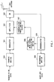
- Illustrated in Fig.1 is a functional block diagram of the mobile station in TDD radio transmission system for making a conventional open loop type transmission power control.
- open loop type is meant a mode of making a communication wherein the mobile station voluntarily decides the transmission power to the base station.
- This communication system comprises a frame assembly device 500 for framing a data to be transmitted, a modulator 501 for modulating the data, an amplifier 502 for amplifying modulated radio waves, a transmitting/receiving changing switch 503 for changing transmit-receive timing of the TDD, an antenna 504 for transmitting and receiving the radio waves, a demodulator 505 for demodulating a received data, a desired wave signal calculation device 506 for calculating a power of a desired wave signal (a desired wave signal at the time of an actual communication) from the demodulated data, a transmission power control device 507 for deciding a transmission power value of the mobile station, and a frame decomposition device 508 for taking out a data by decomposing the frame-composed data.
- the radio waves received from the base station are received by the antenna 504 and input to the demodulator 505 via the transmitting/receiving changing switch 503.
- the data is demodulated by assuming a propagation path and the demodulated data is input to the frame decomposition device 508 and the desired wave signal calculation device 506.
- the frame composed data input to the frame decomposition device 508 is decomposed here and necessary components alone are taken out and output as received data.
- the desired wave signal calculation device 506 calculation of a received signal power is made and the calculated received power value is input to the transmission power control device 507.
- the transmission power value in the base station is memorized and a propagation loss from the base station to the mobile station is calculated from the transmission power value and the desired wave signal received power value.
- PMS[dBm] is the transmission power value of the mobile station
- PTG[dBm] is the target level in the base station
- PBS[dBm] is the transmission power of the base station
- RMS[dBm] is the desired wave signal received power.
- PBS -RMS is the propagation loss.
- the radio waves modulated by the modulator 501 is amplified by the amplifier 502 into the transmission power value which is decided by the above described expression (1) and transmitted from the antenna 504 via the transmitting/receiving changing switch 503.
- the transmission power control is effected as above.
- the received power of the desired wave signal can not be accurately measured if a signal to noise power ratio (SNR) or a signal to interference power ratio (SIR) is low in the mobile station.
- SNR signal to noise power ratio
- SIR signal to interference power ratio
- the present invention is made in view of the above circumstances and it is the object of the present invention to provide the radio communication apparatus and the radio communication system which can prevent the transmission power from suddenly increasing or a big interference from being caused to other users when the received power of the desired wave signal from the other station is erroneously measured or when a level of the received signal is suddenly made small in one's own station.
- the present invention provides the radio communication apparatus, comprising a transmission power control section for controlling the transmission power of a radio communication data at a prescribed period, an allowance storing section for storing a maximum allowance at one period, and a restricting section for restricting the transmission power value of this time to the value of the transmission power value of the previous time added to said maximum allowance in the situation when the difference between the transmission power value of the previous time and the transmission power value of this time exceeds the maximum allowance.
- the present invention when the measurement of the received power of the desired wave signal from the other station is greatly mistaken or even when the level of the received signal is suddenly made small, causing a big interference to other user can be prevented without suddenly increasing the transmission power.
- the present invention provides the radio communication apparatus, further comprising a function for measuring an interference situation with other station from a ratio of the desired wave signal to the interference power of the received signal received from other station and a function for adaptively controlling the maximum allowance according to the measured interference situation.
- how much the transmission power can be allowable as an interference amount given to other station is presumed from a presumed interference amount and can be reflected on the maximum allowance.
- the present invention provides the radio communication apparatus, further comprising a function for measuring fluctuation of the received level and a function for suitably changing the maximum allowance according to the measured received level.
- the maximum allowance is suitably changed according to fluctuation of the measured received level, causing a big interference to other user can voluntarily be prevented.
- the present invention provides the radio communication apparatus, wherein the maximum allowance of the transmission power is stored in the allowance storing section separately according to the cases when the transmission power is increased and when the transmission power is decreased and a restriction is imposed to a change amount separately according to the cases when the restricting section increases or decreases the transmission power.
- the transmission power when the transmission power having a possibility of causing an interference to other station is increased, the transmission power is given a restriction so as not to increase suddenly .
- the transmission power can be dynamically controlled to a certain extent.
- the present invention offers the radio communication apparatus wherein the maximum allowance is instructed from other station.
- the base station calculates the interference with other mobile station and, by instructing the maximum allowance of the transmission power of the mobile station, can prevent causing an interference among other mobile stations, while watching the interference from other users
- the present invention offers the method , comprising a step for calculating the transmission power, a step for comparing a difference between the transmission power value of the previous time and the transmission power value of this time, and a step for restricting the transmission power value of this time to the value of the transmission power of this time added with the maximum allowance in the situation where the transmission power is increased when the difference between the transmission power value of the previous time and the transmission power value of this time exceeds the maximum allowance.
- FIG.2A Illustrated in Fig.2A is a block diagram to show a mobile station in the radio communication system according to the first embodiment of the present invention.
- Fig.2B is a block diagram of a transmission power control device 101 with which the mobile station is equipped. Note that the same sign is given to the section having the same function with each section of the device as shown in Fig.1
- a transmission power restriction device 100 for limiting a maximum change of transmission power is connected to the transmission power control device 101.
- the transmission power control device 101 is constituted by comprising the transmission power memory section 110 for memorizing the transmission power value of the other station (for example, a base station), a target level memory section 111 for memorizing a target level in the other station, a propagation loss calculation section 112 for obtaining a propagation loss from the other station in communication to this station by subtracting the transmission power of a desired wave signal calculated in a desired wave signal level calculation device 506 from a transmission power value memorized in the transmission power memory section 110, a transmission power calculation section 113 for obtaining a temporary transmission power value by adding the propagation loss to the target level memorized in the target level memory section 111, and a transmission power decision section 114 wherein the transmission power value of the previous time is compared to a temporary transmission power value and when the temporary transmission power value exceeds the transmission power value
- radio waves received by an antenna 504 from the base station are input to the demodulator 505 via a transmitting/receiving changing switch 503 for demodulating.
- the demodulated data is input to a deframing device 508 and a desired signal wave calculation section 506.
- a frame of the demodulated data is deframed and each data is taken out and output as a received data.
- a desired wave signal calculation device 506 calculation of the received signal power of the desired wave signal is made and input to the transmission power control device 101.
- a maximum allowance of the transmission power changed in one duration for control the transmission power is output to the transmission power control device 101 from the transmission power restriction device 100 so as not to cause a sudden interference to other user's mobile station in the transmission power control device 101.
- the propagation loss from the other station in communication with this station is presumed.
- the value of the propagation loss added to the target level on the base station is represented by a candidate of the transmission power value.
- the transmission power value obtained by adding the maximum allowance of variable transmission power of the previous time is represented by the transmission power value of this time and, in the case otherwise, the candidate of the transmission power value is input as it is to the amplifier 502 as the transmission power value of this time.
- conditional expressions (4) and (5) may be given by (8) and (9): [ ⁇ P(n) - ⁇ P(n-1)] ⁇ L [ ⁇ P(n) - ⁇ P(n-1)] ⁇ L
- the transmission power value is decided by the conditional expressions (4) and (5).
- the amplifier 502 amplifies a signal which is input from the modulator 501 and the amplified signal is transmitted from the antenna 504 via the transmitting/receiving changing switch 503.
- Fig.2A was described as the constitution of the mobile station, but it can be applied to the constitution of the base station as well.
- the maximum allowance of the transmission power of the station in a period of the transmission power control is set up by the transmission power restriction device 100 and, after the transmission power value of the station is temporarily obtained by the transmission power control device 101, a comparison is made between the maximum allowance of the transmission power and the temporary transmission power value. And when the difference thereof is more than the maximum allowance , the transmission power control is made by the transmission power value where the maximum allowance is added to the transmission power of the previous time.
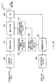
- FIG.3A Illustrated in Fig.3A is a block diagram of a base station in the radio transmission system according to the second embodiment of the present invention.
- Fig.3B shows a block diagram of a mobile station in the radio transmission system. Note that the same sign is given to the section having the same function with each section of the first embodiment as shown in Fig.2.
- the base station as shown in Fig.3A comprises a framing device 200 for composing a transmitting data into a data of a frame unit, a modulator 201 for modulating the framed data, an amplifier 202 for amplifying a power of modulated wave, a switch 203 for changing transmission and reception, an antenna 204 for transmission and reception, a demodulator 205 for demodulating a received data, a SIR measurement device 206 for measuring a ratio of the desired wave signal and the interference power (SIR), a transmission power restriction value decision device 207 for deciding a restriction value of the maximum allowance of the transmission power of the transmission power control by a result of SIR, and a deframing device 208 for taking out a data from the frame composed data.
- a framing device 200 for composing a transmitting data into a data of a frame unit
- a modulator 201 for modulating the framed data
- an amplifier 202 for amplifying a power of modulated wave
- a switch 203
- the characteristics of the base station as constituted above according to the second embodiment of the present invention is that the maximum allowance of the transmission power in the transmission power control is decided on the basis of the result of SIR by the transmission power restriction value decision device 207 and this maximum allowance is transmitted to the mobile station.
- the characteristics of the mobile station as shown in Fig.3B is that the maximum allowance transmitted from the base station is demodulated by the demodulator 505 and output to the transmission power restriction device 210 and the transmission power restriction device 210 sets the maximum allowance of the transmission power of one's own station changed at one period for the power control and outputs the set up maximum allowance to the transmission power control device 101.
- the radio waves are input to the demodulator 205 via the transmitting/receiving changing switch 203.
- the data demodulated by the demodulator 205 is input to the SIR measurement device 206 and here the SIR in relation to the user is measured.
- the value of the measured SIR is input to the transmission power restriction value decision device 207.
- the transmission power restriction value decision device 207 when the SIR is low against a target power in the base station, it is assumed that the situation has arisen where an interference from other user is much and when the SIR is high, it is assumed that the situation has arisen where the interference from other user is little. Consequently, by assuming to what extent the transmission power of the mobile station constituting an interference component to other user can be allowed, the maximum allowance of the transmission power changed at one control period is decided.
- the interference amount from other user is assumed here on the basis of the result of the SIR, the interference amount may be assumed on the basis of a traffic amount recognized by the base station and the maximum allowance of the transmission power changed at one control period may be decided.
- the transmission power restriction value L*[dB] is decided.
- This information about L* is put on a control channel and frame-assembled by the framing device 200 and transmitted via the demodulator 201, the amplifier 202, the transmitting/receiving changing switch 203 and the antenna 204.
- the radio waves received by the antenna 214 are input to the demodulator via the transmitting/receiving changing switch 213 and here the maximum allowance transmitted from the base station is demodulated.
- the maximum allowance of the transmission power changed in one control period is decided on the basis of the transmission power restriction value and is output to the transmission power control device 101.
- the transmission power control device 101 similar to the first embodiment, the maximum allowance of the transmission power is restricted and the transmission power is decided and the sending control is made.
- Fig.3A is described as the constitution of the base station and Fig.3B as the constitution of the mobile station, but the constitution thereof may be reversed with each other.
- the mobile station in the radio transmission system making the transmission power control of the open loop type through the TDD transmission comprises the transmission power restriction device 210 for learning from the base station the instruction of the maximum allowance of the transmission power of the mobile station in the control period of the transmission power and the transmission power control device 101 for deciding the transmission power value on the basis of the maximum allowance from the transmission power restriction device 210, while the base station comprises the transmission power restriction value decision device 207 for instructing the maximum allowance of the transmission power in the control period of the transmission power control and, upon calculating the interference between the mobile station and other user in the base station, instructs the maximum allowance of the transmission power of the mobile station in the control period of the transmission power control of each station, thereby preventing the interference given among each station, while watching the interference from other user.
- Fig.4 shows a block diagram of the mobile station in the radio transmission system according to the third embodiment of the present invention. Note that the same sign is given to the section corresponding to each section of the first embodiment as shown in Fig.2 in the third embodiment as shown in Fig.4 and the description thereof will be omitted accordingly.
- the characteristics of the mobile station as shown in Fig.4 is that fluctuation of a received level is measured in a received level fluctuation measurement device 300 and a transmission power restriction device 210 suitably changes and sets the maximum allowance of the transmission power of the station according to fluctuation of the received level previously measured, thereby the set up maximum allowance is output to a transmission power control device 101.
- the action of the mobile station constituted as above will be described in details as follows.
- the radio waves from the base station are received by an antenna 504 and input to a demodulator 505 via a transmitting/receiving changing switch 503.
- a doppler frequency fD of a fading is estimated from fluctuation of the received level.
- the received level fluctuation measurement device here is one example of assuming the doppler frequency and other means may be used if the similar one corresponding to the doppler frequency can be measure.
- a transmission power restriction device 301 decides the maximum allowance L.
- the function g(x, y) is the function for deciding to what extent the transmission power should be changed so as to follow up the doppler frequency per one control period. This maximum allowance is input to the transmission power control device 101 and decides the transmission power in the similar manner to the first embodiment.
- Fig.4 is described as the constitution of the mobile station, but this constitution can be applied to the base station as well.
- the fluctuation of the received level is measured by the received level fluctuation measurement device 300 and the transmission power restriction device 210 suitably changes and sets the maximum allowance of the transmission power of one's own station changed in one control period according to the fluctuation of the received level previously measured and the set up maximum allowance is output to the transmission power control device 101 and the transmission power is decided, thereby a big interference given to other user can be prevented.
- FIG.5 Illustrated in Fig.5 is a block diagram of a transmission power control device according to the fourth embodiment of the present invention.
- the transmission power control device 400 as shown in Fig.5 conforms to either one of the transmission power control devices as shown in Fig.2 to Fig.4 with the signs 100, 210 and 301.
- the transmission power restriction device 400 imposes a restriction to the maximum allowance of the transmission power at the time of an open loop transmission power controlling and comprises a transmission power increase restriction device 401 for imposing a restriction when the transmission power is increased and a transmission power decrease restriction device 402 for imposing a restriction when the transmission power is decreased.
- the transmission power control device constituted as above will be described in details as follows.
- the maximum control amount in the control period of the transmission power was the same in whichever cases the transmission power was increased or decreased
- a transmission power restriction device 400 when the transmission power is increased, it is made not increased more than the transmission power value specified by a transmission power increase restriction device 401 and, when decreased, not decreased less than the transmission power value specified by a transmission power decrease restriction device 402 so that the transmission power set up separately by the restriction is input to the transmission power control device 101.
- the transmission power restriction device 400 is provided for setting up a restriction separately to the transmission power when the transmission power is increased or when the transmission power is decreased in relation to the maximum allowance in the control period of the transmission power and when the transmission power capable of giving the interference to other user is increased.
- the transmission power is restricted so as not to increase suddenly or when the transmission power not capable of giving the interference is decreased, a restriction is separately set up so that the transmission power can be controlled to a certain extent, thereby a big interference given to other user can be prevented.
Abstract
Description
- The present invention relates to a radio communication apparatus and a radio communication system which is effective for transmit power control in TDD (Time Division Duplex) transmission making a communication by time sharing of transmission-reception with the same frequency.
- There is a CDMA (Code Division Multiple Access) system available as a Multiple Access in which many communication stations mutually communicate by using a specific frequency band allotted. The CDMA is one of spread spectrum communications.
- In the spread spectrum communication, a transmitting node multiplies information-modulated data by a so-called spreading code which is a code of fast rate than information data and transmits the spread data by spreading the spreading code into a wide bandwidth, while a receiving node multiplies a received spread data by the same spreading code on the same timing with the transmitting side .
- The CDMA is an access method utilizing the spread spectrum communication wherein a different code is allotted to each user and the same frequency band width can be used by each user even between cells.
- By the way, when the CDMA is used by a mobile communication, near far problem is arisen. When a plurality of the mobile stations transmit radio waves by the same transmission power to a base station, the radio waves from the station near to the base station are received in a large power as compared to a station far from the base station.
- In the CDMA system, since the same frequency band is owned jointly by all users, the high power radio waves from the station near to the base station tend to cause a large interference to the radio waves from the station far from the base station. In order to accommodate effectively many users within the cells, it is necessary that a signal level arriving at the base station is made equal. One of the technological solutions for the near far problem as described above is to control the transmission power.
- Further, as a problem particular to the mobile communication, there is a phenomenon called a fading. The fading is a phenomenon, wherein it is well known that the radio waves rarely arrive at the mobile station directly from the base station, but arrive in mutually interfered forms of many waves reflected, deflected and dispersed by surrounding buildings, etc. And therefore amplitude and phase of received signals are made to fluctuate at random.
- Also, the changing speed of the received signals is in proportion to the speed of mobile . A transmission power control can follow up the fading of a certain speed.
- Illustrated in Fig.1 is a functional block diagram of the mobile station in TDD radio transmission system for making a conventional open loop type transmission power control. By the open loop type is meant a mode of making a communication wherein the mobile station voluntarily decides the transmission power to the base station.
- This communication system comprises a
frame assembly device 500 for framing a data to be transmitted, amodulator 501 for modulating the data, anamplifier 502 for amplifying modulated radio waves, a transmitting/receiving changingswitch 503 for changing transmit-receive timing of the TDD, anantenna 504 for transmitting and receiving the radio waves, ademodulator 505 for demodulating a received data, a desired wavesignal calculation device 506 for calculating a power of a desired wave signal (a desired wave signal at the time of an actual communication) from the demodulated data, a transmissionpower control device 507 for deciding a transmission power value of the mobile station, and aframe decomposition device 508 for taking out a data by decomposing the frame-composed data. - The action of the TDD radio transmission system as constituted above will be described in details as follows.
- First, the radio waves received from the base station are received by the
antenna 504 and input to thedemodulator 505 via the transmitting/receivingchanging switch 503. In thedemodulator 505, the data is demodulated by assuming a propagation path and the demodulated data is input to theframe decomposition device 508 and the desired wavesignal calculation device 506. - The frame composed data input to the
frame decomposition device 508 is decomposed here and necessary components alone are taken out and output as received data. - On the other hand, in the desired wave
signal calculation device 506, calculation of a received signal power is made and the calculated received power value is input to the transmissionpower control device 507. - In the transmission
power control device 507, the transmission power value in the base station is memorized and a propagation loss from the base station to the mobile station is calculated from the transmission power value and the desired wave signal received power value. The transmission power value is represented by the value added with a target level in the base station (the level in which the base station can correctly receive radio waves) and the propagation loss. This transmission power value is calculated by the following expression - Note that PMS[dBm] is the transmission power value of the mobile station, PTG[dBm] is the target level in the base station, PBS[dBm] is the transmission power of the base station and RMS[dBm] is the desired wave signal received power. (PBS -RMS) is the propagation loss.
- The radio waves modulated by the
modulator 501 is amplified by theamplifier 502 into the transmission power value which is decided by the above described expression (1) and transmitted from theantenna 504 via the transmitting/receivingchanging switch 503. Thus, the transmission power control is effected as above. - However, in the conventional radio transmission system, the received power of the desired wave signal can not be accurately measured if a signal to noise power ratio (SNR) or a signal to interference power ratio (SIR) is low in the mobile station. When the received power value of the desired wave signal is erroneously measured, there are cases where the transmission power is suddenly increased. Also in the case that a cellular telephone is adapted, the moment the mobile station moves into the shady side of buildings, a level of the received signal is suddenly increased. At this moment, there are frequent occasions when transmission is suddenly made with a big power and ,as a result, a big interference is caused to the radio waves of other users mobile stations.
- The present invention is made in view of the above circumstances and it is the object of the present invention to provide the radio communication apparatus and the radio communication system which can prevent the transmission power from suddenly increasing or a big interference from being caused to other users when the received power of the desired wave signal from the other station is erroneously measured or when a level of the received signal is suddenly made small in one's own station.
- The present invention provides the radio communication apparatus, comprising a transmission power control section for controlling the transmission power of a radio communication data at a prescribed period, an allowance storing section for storing a maximum allowance at one period, and a restricting section for restricting the transmission power value of this time to the value of the transmission power value of the previous time added to said maximum allowance in the situation when the difference between the transmission power value of the previous time and the transmission power value of this time exceeds the maximum allowance.
- According to the present invention, when the measurement of the received power of the desired wave signal from the other station is greatly mistaken or even when the level of the received signal is suddenly made small, causing a big interference to other user can be prevented without suddenly increasing the transmission power.
- Also, the present invention provides the radio communication apparatus, further comprising a function for measuring an interference situation with other station from a ratio of the desired wave signal to the interference power of the received signal received from other station and a function for adaptively controlling the maximum allowance according to the measured interference situation.
- According to the present invention, how much the transmission power can be allowable as an interference amount given to other station is presumed from a presumed interference amount and can be reflected on the maximum allowance.
- Also, the present invention provides the radio communication apparatus, further comprising a function for measuring fluctuation of the received level and a function for suitably changing the maximum allowance according to the measured received level.
- According to the present invention, since the maximum allowance is suitably changed according to fluctuation of the measured received level, causing a big interference to other user can voluntarily be prevented.
- Also, the present invention provides the radio communication apparatus, wherein the maximum allowance of the transmission power is stored in the allowance storing section separately according to the cases when the transmission power is increased and when the transmission power is decreased and a restriction is imposed to a change amount separately according to the cases when the restricting section increases or decreases the transmission power.
- According to the present invention, when the transmission power having a possibility of causing an interference to other station is increased, the transmission power is given a restriction so as not to increase suddenly . When the transmission power having not a possibility of causing an interference is decreased, the transmission power can be dynamically controlled to a certain extent.
- Also, the present invention offers the radio communication apparatus wherein the maximum allowance is instructed from other station.
- According to the present invention, the base station calculates the interference with other mobile station and, by instructing the maximum allowance of the transmission power of the mobile station, can prevent causing an interference among other mobile stations, while watching the interference from other users
- Also, the present invention offers the method , comprising a step for calculating the transmission power, a step for comparing a difference between the transmission power value of the previous time and the transmission power value of this time, and a step for restricting the transmission power value of this time to the value of the transmission power of this time added with the maximum allowance in the situation where the transmission power is increased when the difference between the transmission power value of the previous time and the transmission power value of this time exceeds the maximum allowance.
-
- Fig.1 is a block diagram of the conventional radio communication system.
- Fig.2A is a block diagram of the radio communication system according to the first embodiment of the present invention.
- Fig.2B is a block diagram of a transmission power control apparatus comprised in the radio transmission system according to the first embodiment.
- Fig.3A is a block diagram of the base station in the radio transmission system according to the second embodiment of the present invention.
- Fig.3B is a block diagram of a mobile station in the radio transmission system according to the second embodiment.
- Fig.4 is a block diagram of the radio transmission system according to the fourth embodiment of the present invention.
- Fig.5 is a block diagram of the transmission power restricting device in the radio transmission system according to the fourth embodiment of the present invention.
-
- Illustrated in Fig.2A is a block diagram to show a mobile station in the radio communication system according to the first embodiment of the present invention. Fig.2B is a block diagram of a transmission
power control device 101 with which the mobile station is equipped. Note that the same sign is given to the section having the same function with each section of the device as shown in Fig.1 - In the mobile station as shown in Fig.2A, a transmission
power restriction device 100 for limiting a maximum change of transmission power is connected to the transmissionpower control device 101. As shown in Fig.2B, the transmissionpower control device 101 is constituted by comprising the transmissionpower memory section 110 for memorizing the transmission power value of the other station (for example, a base station), a targetlevel memory section 111 for memorizing a target level in the other station, a propagationloss calculation section 112 for obtaining a propagation loss from the other station in communication to this station by subtracting the transmission power of a desired wave signal calculated in a desired wave signallevel calculation device 506 from a transmission power value memorized in the transmissionpower memory section 110, a transmissionpower calculation section 113 for obtaining a temporary transmission power value by adding the propagation loss to the target level memorized in the targetlevel memory section 111, and a transmissionpower decision section 114 wherein the transmission power value of the previous time is compared to a temporary transmission power value and when the temporary transmission power value exceeds the transmission power value of the previous time and the difference thereof is larger than the maximum allowance output from the transmissionpower control device 100, the value of the transmission power of the previous time added with the maximum allowance is decided as the transmission power of this time and, when the difference thereof is small, the temporary transmission power value is decided as the transmission power value of this time. - In the constitution as described above, radio waves received by an
antenna 504 from the base station (not shown in the drawing) are input to thedemodulator 505 via a transmitting/receiving changingswitch 503 for demodulating. The demodulated data is input to adeframing device 508 and a desired signalwave calculation section 506. - In the
deframing device 508, a frame of the demodulated data is deframed and each data is taken out and output as a received data. In a desired wavesignal calculation device 506, calculation of the received signal power of the desired wave signal is made and input to the transmissionpower control device 101. - Here, a maximum allowance of the transmission power changed in one duration for control the transmission power is output to the transmission
power control device 101 from the transmissionpower restriction device 100 so as not to cause a sudden interference to other user's mobile station in the transmissionpower control device 101. - In the transmission
power control device 101, the propagation loss from the other station in communication with this station is presumed. - The value of the propagation loss added to the target level on the base station is represented by a candidate of the transmission power value. In the case that the candidate of the transmission power value changes more than the maximum allowance input from the transmission
power restriction device 100 as against the power value previously sent, the transmission power value obtained by adding the maximum allowance of variable transmission power of the previous time is represented by the transmission power value of this time and, in the case otherwise, the candidate of the transmission power value is input as it is to theamplifier 502 as the transmission power value of this time. - Here, a description will be made about a calculation control made by the transmission
power control device 101 with reference to an expression as follows. First, let the target level in the other station be PTG(dBm), the transmission power value of the other station PBG(dBm), a received power of the desired wave signal in this station RMS(dBm), a restriction value of the maximum allowance of the transmission power changed in one period L(dB) and the transmission power of the station PMS(dBm). The transmission power control is given by the following expression (1), that is to say, - Here, the propagation loss of (PBS - PMS) is represented by ΔP(dB) and the transmission power PMS(n-1) at a time point (n-1) is given by the following expression (2):
- The candidate of the transmission power PMS(n) at the next time point n is given by the following expression (3):
- Here, the following qualified expressions (4) and (5) are considered:
- The transmission power on the conditions of the expression (4) is given by the following expression (6):
- The transmission power on the conditions of the expression (5) is given by the following expression (7):
- When PTG does not change, conditional expressions (4) and (5) may be given by (8) and (9):
- However, there are occasions when PTG and PBS change time-wise. In that case, the transmission power value is decided by the conditional expressions (4) and (5).
- By the transmission power value thus decided as above, the
amplifier 502 amplifies a signal which is input from themodulator 501 and the amplified signal is transmitted from theantenna 504 via the transmitting/receiving changing switch 503. - Note that Fig.2A was described as the constitution of the mobile station, but it can be applied to the constitution of the base station as well.
- Thus, according to the first embodiment, in the radio transmission system for making the transmission power control of the open loop type through the TDD transmission, the maximum allowance of the transmission power of the station in a period of the transmission power control is set up by the transmission
power restriction device 100 and, after the transmission power value of the station is temporarily obtained by the transmissionpower control device 101, a comparison is made between the maximum allowance of the transmission power and the temporary transmission power value. And when the difference thereof is more than the maximum allowance , the transmission power control is made by the transmission power value where the maximum allowance is added to the transmission power of the previous time. Therefore, in one's own station, if the measurement value of the transmission power of the desired wave signal from the other station is greatly mistaken or if a level of the received signal is suddenly made small, giving a big interference to other user can be prevented without causing a sudden increase of the transmission power. - Illustrated in Fig.3A is a block diagram of a base station in the radio transmission system according to the second embodiment of the present invention. Fig.3B shows a block diagram of a mobile station in the radio transmission system. Note that the same sign is given to the section having the same function with each section of the first embodiment as shown in Fig.2.
- The base station as shown in Fig.3A comprises a
framing device 200 for composing a transmitting data into a data of a frame unit, amodulator 201 for modulating the framed data, anamplifier 202 for amplifying a power of modulated wave, aswitch 203 for changing transmission and reception, anantenna 204 for transmission and reception, ademodulator 205 for demodulating a received data, aSIR measurement device 206 for measuring a ratio of the desired wave signal and the interference power (SIR), a transmission power restrictionvalue decision device 207 for deciding a restriction value of the maximum allowance of the transmission power of the transmission power control by a result of SIR, and adeframing device 208 for taking out a data from the frame composed data. - The characteristics of the base station as constituted above according to the second embodiment of the present invention is that the maximum allowance of the transmission power in the transmission power control is decided on the basis of the result of SIR by the transmission power restriction
value decision device 207 and this maximum allowance is transmitted to the mobile station. - The characteristics of the mobile station as shown in Fig.3B is that the maximum allowance transmitted from the base station is demodulated by the
demodulator 505 and output to the transmissionpower restriction device 210 and the transmissionpower restriction device 210 sets the maximum allowance of the transmission power of one's own station changed at one period for the power control and outputs the set up maximum allowance to the transmissionpower control device 101. - The action of the base station and the mobile station constituted as above will be described in details as follows.
- First, in the base station when radio waves are received by the
antenna 204 from the mobile station, the radio waves are input to thedemodulator 205 via the transmitting/receiving changing switch 203. The data demodulated by thedemodulator 205 is input to theSIR measurement device 206 and here the SIR in relation to the user is measured. - The value of the measured SIR is input to the transmission power restriction
value decision device 207. In the transmission power restrictionvalue decision device 207, when the SIR is low against a target power in the base station, it is assumed that the situation has arisen where an interference from other user is much and when the SIR is high, it is assumed that the situation has arisen where the interference from other user is little. Consequently, by assuming to what extent the transmission power of the mobile station constituting an interference component to other user can be allowed, the maximum allowance of the transmission power changed at one control period is decided. - Note that, though the interference amount from other user is assumed here on the basis of the result of the SIR, the interference amount may be assumed on the basis of a traffic amount recognized by the base station and the maximum allowance of the transmission power changed at one control period may be decided.
- That is to say, if the measured SIR is represented by SIRM[dB] and a threshold level value of the SIR by SIRTH * [dB],the following expressions are given to decide the transmission power control value L*[dB]:Thus, the transmission power restriction value L*[dB] is decided.

This information about L* is put on a control channel and frame-assembled by theframing device 200 and transmitted via thedemodulator 201, theamplifier 202, the transmitting/receiving changing switch 203 and theantenna 204. - In the mobile station, the radio waves received by the antenna 214 are input to the demodulator via the transmitting/receiving changing switch 213 and here the maximum allowance transmitted from the base station is demodulated.
- In the transmission
power restriction device 210, the maximum allowance of the transmission power changed in one control period is decided on the basis of the transmission power restriction value and is output to the transmissionpower control device 101. In the transmissionpower control device 101, similar to the first embodiment, the maximum allowance of the transmission power is restricted and the transmission power is decided and the sending control is made. - Note that , according to the second embodiment, Fig.3A is described as the constitution of the base station and Fig.3B as the constitution of the mobile station, but the constitution thereof may be reversed with each other.
- In this manner, according to the second embodiment, the mobile station in the radio transmission system making the transmission power control of the open loop type through the TDD transmission comprises the transmission
power restriction device 210 for learning from the base station the instruction of the maximum allowance of the transmission power of the mobile station in the control period of the transmission power and the transmissionpower control device 101 for deciding the transmission power value on the basis of the maximum allowance from the transmissionpower restriction device 210, while the base station comprises the transmission power restrictionvalue decision device 207 for instructing the maximum allowance of the transmission power in the control period of the transmission power control and, upon calculating the interference between the mobile station and other user in the base station, instructs the maximum allowance of the transmission power of the mobile station in the control period of the transmission power control of each station, thereby preventing the interference given among each station, while watching the interference from other user. - Fig.4 shows a block diagram of the mobile station in the radio transmission system according to the third embodiment of the present invention. Note that the same sign is given to the section corresponding to each section of the first embodiment as shown in Fig.2 in the third embodiment as shown in Fig.4 and the description thereof will be omitted accordingly.
- The characteristics of the mobile station as shown in Fig.4 is that fluctuation of a received level is measured in a received level
fluctuation measurement device 300 and a transmissionpower restriction device 210 suitably changes and sets the maximum allowance of the transmission power of the station according to fluctuation of the received level previously measured, thereby the set up maximum allowance is output to a transmissionpower control device 101. - The action of the mobile station constituted as above will be described in details as follows. The radio waves from the base station are received by an
antenna 504 and input to ademodulator 505 via a transmitting/receiving changing switch 503. In a received levelfluctuation measurement device 300, a doppler frequency fD of a fading is estimated from fluctuation of the received level. Note that the received level fluctuation measurement device here is one example of assuming the doppler frequency and other means may be used if the similar one corresponding to the doppler frequency can be measure. - Whether the control period T of the transmission power control could be followed up is assumed by deciding to what extent the transmission power is changed. Therefore, if the maximum allowance is represented by L(dB), on the basis of the following expression (10),
power restriction device 301 decides the maximum allowance L. Here, the function g(x, y) is the function for deciding to what extent the transmission power should be changed so as to follow up the doppler frequency per one control period. This maximum allowance is input to the transmissionpower control device 101 and decides the transmission power in the similar manner to the first embodiment. - Note that, in the above, Fig.4 is described as the constitution of the mobile station, but this constitution can be applied to the base station as well.
- In this manner, according to the third embodiment, the fluctuation of the received level is measured by the received level
fluctuation measurement device 300 and the transmissionpower restriction device 210 suitably changes and sets the maximum allowance of the transmission power of one's own station changed in one control period according to the fluctuation of the received level previously measured and the set up maximum allowance is output to the transmissionpower control device 101 and the transmission power is decided, thereby a big interference given to other user can be prevented. - Illustrated in Fig.5 is a block diagram of a transmission power control device according to the fourth embodiment of the present invention.
- The transmission
power control device 400 as shown in Fig.5 conforms to either one of the transmission power control devices as shown in Fig.2 to Fig.4 with thesigns - The transmission
power restriction device 400 imposes a restriction to the maximum allowance of the transmission power at the time of an open loop transmission power controlling and comprises a transmission powerincrease restriction device 401 for imposing a restriction when the transmission power is increased and a transmission powerdecrease restriction device 402 for imposing a restriction when the transmission power is decreased. - The action of the transmission power control device constituted as above will be described in details as follows. In the transmission power control device according to the embodiments from 1 to 3, the maximum control amount in the control period of the transmission power was the same in whichever cases the transmission power was increased or decreased
- However, in case of a transmission
power restriction device 400, when the transmission power is increased, it is made not increased more than the transmission power value specified by a transmission powerincrease restriction device 401 and, when decreased, not decreased less than the transmission power value specified by a transmission powerdecrease restriction device 402 so that the transmission power set up separately by the restriction is input to the transmissionpower control device 101. - Here, let the upper limit of the maximum allowance of the transmission power be represented by the LUP and the lowest limit by LDOWN. If the transmission power PMS(n-1) of the station at a time point n-1 is given by the following expression(11),
- In this manner, according to the fourth embodiment, the transmission
power restriction device 400 is provided for setting up a restriction separately to the transmission power when the transmission power is increased or when the transmission power is decreased in relation to the maximum allowance in the control period of the transmission power and when the transmission power capable of giving the interference to other user is increased., the transmission power is restricted so as not to increase suddenly or when the transmission power not capable of giving the interference is decreased, a restriction is separately set up so that the transmission power can be controlled to a certain extent, thereby a big interference given to other user can be prevented. - It is to be noted that all the embodiments from 1 to 4 as described above can be practiced in TDMA (Time Division Multiple Access) and CDMA (Code Division Multiple Access).
Claims (17)
- A radio communication apparatus comprising:transmission power control means(101) for controlling a transmission power of a radio transmission data in a given period,allowance storing means(100) for storing a maximum allowance of the transmission power in one period, andrestriction means(100) for restricting the transmission power value of this time to the value of the transmission power value of the previous time added with said maximum allowance when the difference between the transmission power value of the previous time and the transmission power value of this time exceeds said maximum allowance in the situation where the transmission power is increased.
- The radio communication apparatus according to Claim 1, further comprising;means(210) for measuring an interference with other communication station from a ratio of a desired wave signal to an interference transmission power of a received signal received from other communication station, andmeans(210) for adaptively controlling said maximum allowance according to the measured interference.
- The radio communication apparatus according to Claim 1, further comprising;means(300) for measuring fluctuation of a received level of a receiving signal, andmeans(301) for adaptively changing said maximum allowance according to the measured received level.
- The radio communication apparatus according to Claim 1, wherein said allowance storing means(401,402) stores the maximum allowance of the transmission power separately according to the cases where the transmission power is increased and where the transmission power is decreased, andsaid restriction means(400) imposes restriction to a change amount of the transmission power separately according to the cases when the transmission power is increased and when the transmission power is decreased.
- The radio communication apparatus according to claim 4, wherein the maximum allowance corresponding to the case where the transmission power is decreased is relatively larger than the maximum allowance according to the case where the transmission power is decreased.
- The radio communication apparatus according to claim 1, wherein the maximum allowance stored in said allowance storing means(100) is instructed from other communication station.
- The radio communication apparatus according to claim 1, wherein said radio communication apparatus communicates with another communication station in time division duplex in which transmission and reception is switched on time sharing.
- The radio communication apparatus according to claim 7, wherein said radio communication apparatus communicate with the another communication station in time division duplex by open loop type which decides the transmission power on the basis of the desired wave signal power included in the demodulation data.
- The radio communication apparatus according to claim 1, wherein said transmission power control means(101) comprises:first memory means(110) for memorizing the transmission power value of the other communication station,second memory means (111) for memorizing a target level in said other communication station,first calculation means(112) for calculating propagation loss to said other communication station by subtracting the received power value of the received signal received from said other communication station from the transmission power value memorized in said first memory means(110), andsecond calculation means(113) for calculating a temporary transmission power value by adding said propagation loss to said target level,in which said restriction means(100) treats the value of said maximum allowance added to the transmission power of the previous time as the transmission power of this time when the difference between said temporary transmission power value and the transmission power value of this time is larger than said maximum allowance, and treats said temporary transmission power value as the transmission power value of this time when said difference is smaller than said maximum allowance.
- A mobile station having the radio communication apparatus as described in any one of claim 1 to 9.
- A base station having the radio communication apparatus as claimed in any one of claim 1 to 9.
- The base station performing the radio communication with the mobile station as claimed in Claim 10, comprisingallowable decision means(207) for deciding the maximum allowance of said mobile station on the basis of communication environment, andmeans(200,202,202,204) for performing radio transmission of the decided maximum allowance to said mobile station .
- The base station according to claim 12, wherein said allowance decision means(207) comprisesmeans(206) for measuring a ratio of the desired wave signal to the interference power regarding said mobile station from the received data received from said mobile station , andmeans(207) for calculating the maximum allowance of said mobile station on the basis of the measured ratio of the desired wave signal to the interference power.
- A radio communication system, comprising a base station and the mobile station as claimed in Claim 10 for performing the radio communication with the base station .
- A method for controlling the transmission power of a radio communication apparatus, comprising the steps of :calculating the transmission power,comparing the difference between the transmission power value of the previous time and the transmission power value of this time, andrestricting the transmission power value of this time to the value added the transmission power value of the previous time to the maximum allowance when the difference between the transmission power value of the previous time and the transmission power value of this time exceeds the maximum allowance in the situation where the transmission power is increased.
- The method according to claim 15, further comprising the steps of measuring fluctuation of a received level, and adaptively changing said maximum allowance according to the measured received level.
- The method according to claim 15, wherein restriction is imposed to fluctuating amount of the transmission power separately in the cases where the transmission power is increased and where decreased.
Applications Claiming Priority (3)
| Application Number | Priority Date | Filing Date | Title |
|---|---|---|---|
| JP323818/97 | 1997-11-10 | ||
| JP32381897 | 1997-11-10 | ||
| JP9323818A JPH11145899A (en) | 1997-11-10 | 1997-11-10 | Transmission/reception equipment and radio transmission system |
Publications (2)
| Publication Number | Publication Date |
|---|---|
| EP0917302A1 true EP0917302A1 (en) | 1999-05-19 |
| EP0917302B1 EP0917302B1 (en) | 2001-06-20 |
Family
ID=18158951
Family Applications (1)
| Application Number | Title | Priority Date | Filing Date |
|---|---|---|---|
| EP98107278A Expired - Lifetime EP0917302B1 (en) | 1997-11-10 | 1998-04-21 | Radio communication apparatus and radio communication system |
Country Status (7)
| Country | Link |
|---|---|
| US (1) | US6138033A (en) |
| EP (1) | EP0917302B1 (en) |
| JP (1) | JPH11145899A (en) |
| KR (1) | KR100360178B1 (en) |
| CN (1) | CN1158789C (en) |
| CA (1) | CA2235382C (en) |
| DE (1) | DE69800961T2 (en) |
Cited By (3)
| Publication number | Priority date | Publication date | Assignee | Title |
|---|---|---|---|---|
| EP1079539A2 (en) * | 1999-08-25 | 2001-02-28 | Nec Corporation | Communication apparatus having a transmission power controller |
| EP1091503A2 (en) * | 1999-10-06 | 2001-04-11 | Lucent Technologies Inc. | Method and apparatus for reverse link power control |
| WO2004073204A1 (en) * | 2003-02-13 | 2004-08-26 | Telefonaktiebolaget L M Ericsson (Publ) | Wireless transceivers, methods, and computer program products for restricting transmission power based on signal- to-interference ratios |
Families Citing this family (16)
| Publication number | Priority date | Publication date | Assignee | Title |
|---|---|---|---|---|
| US6977967B1 (en) | 1995-03-31 | 2005-12-20 | Qualcomm Incorporated | Method and apparatus for performing fast power control in a mobile communication system |
| TW347616B (en) * | 1995-03-31 | 1998-12-11 | Qualcomm Inc | Method and apparatus for performing fast power control in a mobile communication system a method and apparatus for controlling transmission power in a mobile communication system is disclosed. |
| US6628630B1 (en) | 1997-04-15 | 2003-09-30 | Matsushita Electric Industrial Co., Ltd. | Spread spectrum communication method |
| JPH11196456A (en) * | 1998-01-05 | 1999-07-21 | Oki Electric Ind Co Ltd | Transmission power controller |
| JP3199238B2 (en) * | 1998-09-18 | 2001-08-13 | 日本電気株式会社 | Transmission power control system and transmission power control method in code division multiple access system |
| US6493541B1 (en) * | 1999-07-02 | 2002-12-10 | Telefonaktiebolaget Lm Ericsson (Publ) | Transmit power control time delay compensation in a wireless communications system |
| US6449489B1 (en) * | 1999-09-14 | 2002-09-10 | Lucent Technologies Inc. | Method and apparatus for adaptive adjustments of user probe signal |
| CA2401126C (en) * | 2000-02-23 | 2010-11-09 | George Rodney Nelson Jr. | Access probe acknowledgement with collision detection |
| US8199696B2 (en) | 2001-03-29 | 2012-06-12 | Qualcomm Incorporated | Method and apparatus for power control in a wireless communication system |
| JP4606668B2 (en) * | 2001-09-17 | 2011-01-05 | Okiセミコンダクタ株式会社 | Power control circuit and power control method |
| US20040198261A1 (en) * | 2002-06-28 | 2004-10-07 | Wei Xiong | Method of self-calibration in a wireless transmitter |
| JP3970177B2 (en) * | 2002-12-26 | 2007-09-05 | パナソニック モバイルコミュニケーションズ株式会社 | Wireless communication device |
| EP1848122B8 (en) | 2005-02-09 | 2010-03-03 | Mitsubishi Electric Corporation | Radio device and interference avoiding method by transmission power control |
| US7519329B2 (en) * | 2005-07-01 | 2009-04-14 | Research In Motion Limited | Determination of antenna noise temperature for handheld wireless devices |
| JP2014517579A (en) * | 2011-05-05 | 2014-07-17 | 富士通株式会社 | Power compensation method, user equipment and base station |
| US10947772B2 (en) | 2017-10-24 | 2021-03-16 | Quaker Window Products Co. | Thermally enhanced multi-component glass doors and windows |
Citations (4)
| Publication number | Priority date | Publication date | Assignee | Title |
|---|---|---|---|---|
| US5267262A (en) * | 1989-11-07 | 1993-11-30 | Qualcomm Incorporated | Transmitter power control system |
| WO1995023460A1 (en) * | 1994-02-28 | 1995-08-31 | Qualcomm Incorporated | Method and apparatus for correction and limitation of transmitter power on the reverse link of a mobile radio telephone system |
| US5553316A (en) * | 1992-07-03 | 1996-09-03 | Ncr Corporation | Power control method in a wireless communication system |
| US5564074A (en) * | 1993-02-05 | 1996-10-08 | Nokia Mobile Phones Ltd. | Power control apparatus and method for a radiotelephone |
Family Cites Families (17)
| Publication number | Priority date | Publication date | Assignee | Title |
|---|---|---|---|---|
| DE69231437T2 (en) * | 1991-12-26 | 2001-03-01 | Nec Corp | System for controlling the transmission power with a constant signal quality in a mobile communication network |
| NZ255617A (en) * | 1992-09-04 | 1996-11-26 | Ericsson Telefon Ab L M | Tdma digital radio: measuring path loss and setting transmission power accordingly |
| US5333175A (en) * | 1993-01-28 | 1994-07-26 | Bell Communications Research, Inc. | Method and apparatus for dynamic power control in TDMA portable radio systems |
| WO1994018756A1 (en) * | 1993-02-11 | 1994-08-18 | Motorola, Inc. | Method and apparatus for controlling a power level of a subscriber unit of a wireless communication system |
| JPH07235902A (en) * | 1994-02-23 | 1995-09-05 | Nippon Telegr & Teleph Corp <Ntt> | Transmission power control method/circuit |
| JP2974274B2 (en) * | 1994-05-12 | 1999-11-10 | エヌ・ティ・ティ移動通信網株式会社 | Transmission power control method and transmission power control device |
| US5548616A (en) * | 1994-09-09 | 1996-08-20 | Nokia Mobile Phones Ltd. | Spread spectrum radiotelephone having adaptive transmitter gain control |
| JPH08303544A (en) * | 1995-04-28 | 1996-11-19 | Isuzu Motors Ltd | Toroidal type continuously variable transmission |
| WO1997008847A1 (en) * | 1995-08-31 | 1997-03-06 | Nokia Telecommunications Oy | Method and device for controlling transmission power of a radio transmitter in a cellular communication system |
| US5627857A (en) * | 1995-09-15 | 1997-05-06 | Qualcomm Incorporated | Linearized digital automatic gain control |
| JP2773721B2 (en) * | 1995-12-28 | 1998-07-09 | 日本電気株式会社 | Transmission power control method |
| JP2803626B2 (en) * | 1996-04-05 | 1998-09-24 | 日本電気株式会社 | Transmission power control method for mobile radio terminals |
| KR100194956B1 (en) * | 1996-08-21 | 1999-06-15 | 정선종 | Adaptive Power Control Method for Code Division Multiple Access Mobile Radiotelephone System |
| US5960361A (en) * | 1996-10-22 | 1999-09-28 | Qualcomm Incorporated | Method and apparatus for performing a fast downward move in a cellular telephone forward link power control system |
| US5893036A (en) * | 1997-01-30 | 1999-04-06 | Motorola, Inc. | Transmission power control method |
| US5963870A (en) * | 1997-03-26 | 1999-10-05 | Nortel Networks Corporation | Process for switching between IS-95 forward power control and fast forward power control |
| US5987333A (en) * | 1997-09-30 | 1999-11-16 | Nortel Networks Corporation/Corporation Nortel Networks | Communications power control |
-
1997
- 1997-11-10 JP JP9323818A patent/JPH11145899A/en active Pending
-
1998
- 1998-04-17 US US09/061,226 patent/US6138033A/en not_active Expired - Fee Related
- 1998-04-20 CA CA002235382A patent/CA2235382C/en not_active Expired - Fee Related
- 1998-04-21 EP EP98107278A patent/EP0917302B1/en not_active Expired - Lifetime
- 1998-04-21 DE DE69800961T patent/DE69800961T2/en not_active Expired - Fee Related
- 1998-04-27 KR KR10-1998-0014960A patent/KR100360178B1/en not_active IP Right Cessation
- 1998-04-30 CN CNB981078095A patent/CN1158789C/en not_active Expired - Fee Related
Patent Citations (4)
| Publication number | Priority date | Publication date | Assignee | Title |
|---|---|---|---|---|
| US5267262A (en) * | 1989-11-07 | 1993-11-30 | Qualcomm Incorporated | Transmitter power control system |
| US5553316A (en) * | 1992-07-03 | 1996-09-03 | Ncr Corporation | Power control method in a wireless communication system |
| US5564074A (en) * | 1993-02-05 | 1996-10-08 | Nokia Mobile Phones Ltd. | Power control apparatus and method for a radiotelephone |
| WO1995023460A1 (en) * | 1994-02-28 | 1995-08-31 | Qualcomm Incorporated | Method and apparatus for correction and limitation of transmitter power on the reverse link of a mobile radio telephone system |
Cited By (7)
| Publication number | Priority date | Publication date | Assignee | Title |
|---|---|---|---|---|
| EP1079539A2 (en) * | 1999-08-25 | 2001-02-28 | Nec Corporation | Communication apparatus having a transmission power controller |
| EP1079539A3 (en) * | 1999-08-25 | 2003-10-01 | Nec Corporation | Communication apparatus having a transmission power controller |
| EP1091503A2 (en) * | 1999-10-06 | 2001-04-11 | Lucent Technologies Inc. | Method and apparatus for reverse link power control |
| EP1091503A3 (en) * | 1999-10-06 | 2003-07-09 | Lucent Technologies Inc. | Method and apparatus for reverse link power control |
| US6968201B1 (en) | 1999-10-06 | 2005-11-22 | Lucent Technologies, Inc. | Method and apparatus for controlling reverse link interference rise and power control instability in a wireless system |
| WO2004073204A1 (en) * | 2003-02-13 | 2004-08-26 | Telefonaktiebolaget L M Ericsson (Publ) | Wireless transceivers, methods, and computer program products for restricting transmission power based on signal- to-interference ratios |
| US7149538B2 (en) | 2003-02-13 | 2006-12-12 | Telefonaktiebolaget Lm Ericsson (Publ) | Wireless transceivers, methods, and computer program products for restricting transmission power based on signal-to-interference ratios |
Also Published As
| Publication number | Publication date |
|---|---|
| DE69800961D1 (en) | 2001-07-26 |
| US6138033A (en) | 2000-10-24 |
| DE69800961T2 (en) | 2001-10-04 |
| EP0917302B1 (en) | 2001-06-20 |
| CA2235382C (en) | 2001-10-30 |
| CA2235382A1 (en) | 1999-05-10 |
| JPH11145899A (en) | 1999-05-28 |
| CN1158789C (en) | 2004-07-21 |
| KR19990044721A (en) | 1999-06-25 |
| CN1218342A (en) | 1999-06-02 |
| KR100360178B1 (en) | 2004-05-27 |
Similar Documents
| Publication | Publication Date | Title |
|---|---|---|
| US6138033A (en) | Radio communication apparatus and radio communication system | |
| CA2120768C (en) | Transmitter power control system | |
| FI111111B (en) | A method for controlling the power of a random access packet transmitted by a mobile station in a radio communication system and a system using the method | |
| EP1349294B1 (en) | Weighted open loop power control in a time division duplex communication system | |
| EP0720808B1 (en) | Method and apparatus for balancing the forward link handoff boundary to the reverse link handoff boundary in a cellular communication system | |
| EP2101536B1 (en) | Method and apparatus for controlling transmission power in a CDMA cellular mobile telephone system | |
| EP1001556B1 (en) | CDMA transmissoin power control capable of preventing call disconnection and degradation of capacity of subscribers | |
| US6577668B2 (en) | User equipment utilizing weighted open loop power control | |
| EP0500689B2 (en) | Method and apparatus for controlling transmission power in a cdma cellular mobile telephone system | |
| KR100268145B1 (en) | Method of controlling transmitting power of a base station in a cdma mobile communication system | |
| US5257283A (en) | Spread spectrum transmitter power control method and system | |
| US5485486A (en) | Method and apparatus for controlling transmission power in a CDMA cellular mobile telephone system | |
| US6188678B1 (en) | Method and apparatus for adaptive closed loop power control using open loop measurements | |
| US5604766A (en) | Transmission power control method of a spread-spectrum communication system, and a spread-spectrum communication system employing the control method | |
| US6351649B1 (en) | Mobile communication system | |
| CA2260062A1 (en) | Power presetting in a radio communication system | |
| US20050002422A1 (en) | Information rate contol method, mobile station, radio control apparatus, base station, and mobile communication system | |
| JP3360053B2 (en) | Mobile communication terminal | |
| JPH0226895B2 (en) |
Legal Events
| Date | Code | Title | Description |
|---|---|---|---|
| PUAI | Public reference made under article 153(3) epc to a published international application that has entered the european phase |
Free format text: ORIGINAL CODE: 0009012 |
|
| AK | Designated contracting states |
Kind code of ref document: A1 Designated state(s): DE FR GB NL |
|
| AX | Request for extension of the european patent |
Free format text: AL;LT;LV;MK;RO;SI |
|
| 17P | Request for examination filed |
Effective date: 19990706 |
|
| 17Q | First examination report despatched |
Effective date: 19990806 |
|
| AKX | Designation fees paid |
Free format text: DE FR GB NL |
|
| GRAG | Despatch of communication of intention to grant |
Free format text: ORIGINAL CODE: EPIDOS AGRA |
|
| GRAG | Despatch of communication of intention to grant |
Free format text: ORIGINAL CODE: EPIDOS AGRA |
|
| GRAH | Despatch of communication of intention to grant a patent |
Free format text: ORIGINAL CODE: EPIDOS IGRA |
|
| GRAH | Despatch of communication of intention to grant a patent |
Free format text: ORIGINAL CODE: EPIDOS IGRA |
|
| GRAA | (expected) grant |
Free format text: ORIGINAL CODE: 0009210 |
|
| AK | Designated contracting states |
Kind code of ref document: B1 Designated state(s): DE FR GB NL |
|
| REF | Corresponds to: |
Ref document number: 69800961 Country of ref document: DE Date of ref document: 20010726 |
|
| ET | Fr: translation filed | ||
| REG | Reference to a national code |
Ref country code: GB Ref legal event code: IF02 |
|
| PLBE | No opposition filed within time limit |
Free format text: ORIGINAL CODE: 0009261 |
|
| STAA | Information on the status of an ep patent application or granted ep patent |
Free format text: STATUS: NO OPPOSITION FILED WITHIN TIME LIMIT |
|
| 26N | No opposition filed | ||
| PGFP | Annual fee paid to national office [announced via postgrant information from national office to epo] |
Ref country code: NL Payment date: 20070415 Year of fee payment: 10 |
|
| PGFP | Annual fee paid to national office [announced via postgrant information from national office to epo] |
Ref country code: DE Payment date: 20070419 Year of fee payment: 10 |
|
| PGFP | Annual fee paid to national office [announced via postgrant information from national office to epo] |
Ref country code: GB Payment date: 20070418 Year of fee payment: 10 |
|
| PGFP | Annual fee paid to national office [announced via postgrant information from national office to epo] |
Ref country code: FR Payment date: 20070411 Year of fee payment: 10 |
|
| GBPC | Gb: european patent ceased through non-payment of renewal fee |
Effective date: 20080421 |
|
| NLV4 | Nl: lapsed or anulled due to non-payment of the annual fee |
Effective date: 20081101 |
|
| PG25 | Lapsed in a contracting state [announced via postgrant information from national office to epo] |
Ref country code: NL Free format text: LAPSE BECAUSE OF NON-PAYMENT OF DUE FEES Effective date: 20081101 Ref country code: DE Free format text: LAPSE BECAUSE OF NON-PAYMENT OF DUE FEES Effective date: 20081101 |
|
| REG | Reference to a national code |
Ref country code: FR Ref legal event code: ST Effective date: 20081231 |
|
| PG25 | Lapsed in a contracting state [announced via postgrant information from national office to epo] |
Ref country code: FR Free format text: LAPSE BECAUSE OF NON-PAYMENT OF DUE FEES Effective date: 20080430 |
|
| PG25 | Lapsed in a contracting state [announced via postgrant information from national office to epo] |
Ref country code: GB Free format text: LAPSE BECAUSE OF NON-PAYMENT OF DUE FEES Effective date: 20080421 |