EP0926436A2 - Vibration damper - Google Patents
Vibration damper Download PDFInfo
- Publication number
- EP0926436A2 EP0926436A2 EP98308911A EP98308911A EP0926436A2 EP 0926436 A2 EP0926436 A2 EP 0926436A2 EP 98308911 A EP98308911 A EP 98308911A EP 98308911 A EP98308911 A EP 98308911A EP 0926436 A2 EP0926436 A2 EP 0926436A2
- Authority
- EP
- European Patent Office
- Prior art keywords
- fuel
- tube
- tubes
- damper
- sleeve
- Prior art date
- Legal status (The legal status is an assumption and is not a legal conclusion. Google has not performed a legal analysis and makes no representation as to the accuracy of the status listed.)
- Granted
Links
Images
Classifications
-
- F—MECHANICAL ENGINEERING; LIGHTING; HEATING; WEAPONS; BLASTING
- F23—COMBUSTION APPARATUS; COMBUSTION PROCESSES
- F23D—BURNERS
- F23D11/00—Burners using a direct spraying action of liquid droplets or vaporised liquid into the combustion space
- F23D11/36—Details, e.g. burner cooling means, noise reduction means
-
- F—MECHANICAL ENGINEERING; LIGHTING; HEATING; WEAPONS; BLASTING
- F23—COMBUSTION APPARATUS; COMBUSTION PROCESSES
- F23D—BURNERS
- F23D14/00—Burners for combustion of a gas, e.g. of a gas stored under pressure as a liquid
- F23D14/46—Details, e.g. noise reduction means
-
- F—MECHANICAL ENGINEERING; LIGHTING; HEATING; WEAPONS; BLASTING
- F23—COMBUSTION APPARATUS; COMBUSTION PROCESSES
- F23D—BURNERS
- F23D2210/00—Noise abatement
-
- F—MECHANICAL ENGINEERING; LIGHTING; HEATING; WEAPONS; BLASTING
- F23—COMBUSTION APPARATUS; COMBUSTION PROCESSES
- F23R—GENERATING COMBUSTION PRODUCTS OF HIGH PRESSURE OR HIGH VELOCITY, e.g. GAS-TURBINE COMBUSTION CHAMBERS
- F23R2900/00—Special features of, or arrangements for continuous combustion chambers; Combustion processes therefor
- F23R2900/00005—Preventing fatigue failures or reducing mechanical stress in gas turbine components
Definitions
- the present invention relates to gas turbine engines and more particularly to a vibration damper that limits vibrational effects between concentric tubes in a fuel nozzle.
- a gas turbine engine combustor is typically disposed within an annular combustion section between an inner and an outer engine case wall.
- a plurality of primary fuel nozzles disposed in the upstream end of the combustor supply a mixture of fuel and air axially into the combustor at a closely controlled ratio.
- a plurality of secondary fuel nozzles are disposed in the outer engine case wall. The secondary fuel nozzles supply a mixture of fuel and air radially into the combustor during engine startup and at certain thrust levels. The secondary fuel nozzles are actuated during low and intermediate power regimes to stabilize the flame in the combustor.
- the secondary fuel nozzles include a central axis about which are disposed an inner and an outer concentric fuel tubes.
- the inner tube carries liquid fuel while the outer tube carries fuel supplied as a gaseous fluid (natural gas fuel).
- the gaseous fuel in the outer tube thermally insulates the liquid fuel in the inner tube thereby preventing a problem of coking within the fuel nozzle.
- Coking is a thickening of any residual fuel that is stagnant within the fuel system passages. When stagnant fuel is heated, it solidifies and can reduce effective fuel flow capacity and actually plug the fuel supply system.
- the secondary fuel nozzles are particularly susceptible to coking because fuel tends to stagnate and get heated within the nozzle when the nozzle is not actuated during those thrust settings when only the primary nozzles are operating.
- insulating the inner tube carrying liquid fuel by the outer concentric tube reduces the problem of coking.
- the geometry of the inner and outer concentric tubes is not without problem. It will be appreciated that the environment within a gas turbine engine combustion chamber is extremely harsh. The fuel-air mixture burns in the combustion chamber at temperatures as high as 2100°C (3800°F) causing extreme thermal gradients and therefore, thermal stresses in the inner and outer engine case walls in the combustion section. Moreover, rotational movement of the engine's compressor and turbine, as well as the high flow rate of the fuel-air mixture and the burning thereof, may cause significant vibration and pressure pulsations in the combustion section and engine case walls. Such high thermal stresses and vibration experienced by the combustion section walls are also experienced by the secondary fuel nozzles.
- Prior art secondary fuel nozzles have, in large measure, failed to adequately tolerate such a harsh vibratory and thermal environment without themselves exhibiting vibratory movement. Such movement risks not only the misalignment of the fuel nozzles with other components in the combustor such as igniters, and the like, but also actual damage to the concentric fuel tubes of the nozzles due to relative vibratory movement between the inner and outer fuel tubes.
- the inner and outer fuel tubes may crack due to wear and fatigue caused by the vibratory stresses.
- U.S. Patent Nos. 3,785,407 to Waite et al. and 4,098,476 to Jutte et al. teach an apparatus for a spacer member between a pipe and a cover, and a support apparatus to prevent rotational and translational motion at certain temperatures respectively. While Waite et al. discloses a pipe cover spacer with yieldable fingers extending to make contact with a pipe, it is desirable to dampen vibrations between two tubes in an economical way. The yieldable fingers in Waite's disclosure are separate pieces arranged circumferentially to provide a spacing function. Further, while Jutte et al.
- the present invention provides a fuel injection nozzle for a gas turbine engine having first and second fuel tubes, the second tube radially outside the first, and a vibration damper.
- the vibration damper comprises a sleeve engaging one of the tubes, and at least two legs engaging the other tube. Each leg has a radial portion extending from the sleeve and a resilient, longitudinally extending portion bearing against a surface of the other tube to dampen vibrational effects between the tubes during engine operation.
- a fuel nozzle having a central axis, an inner and an outer concentric fuel tube disposed about the axis, is provided with a vibration damper having a sleeve and at least two legs, each leg having a longitudinally extending portion, the sleeve engaging the inner tube and the longitudinally extending portion of the legs bearing against the inner surface of the outer tube wherein the vibration damper dampens vibrational effects between the concentric fuel tubes during engine operation.
- the legs of the damper are L-shaped, with radially extending portions and resilient longitudinally extending portions.
- the fuel nozzle includes two vibration dampers at spaced locations.
- the second damper is angularly offset from the first damper.
- An advantage of the present invention is the durability and structural integrity of the fuel nozzles due to the vibration damper.
- the vibration damper appreciably reduces the intensity of vibratory forces experienced by the concentric tubes.
- the fuel tubes are thus not subject to wear and fatigue imposed by the vibration forces.
- Another advantage of preferred embodiments of the present invention is minimal fuel flow blockage in the annulus between the inner and outer tube. By angularly offsetting the dampers, the present invention distributes any blockage to the fuel flow in the outer tube. This decreases the pressure drop in the outer tube as compared with a configuration that has the dampers aligned. Further, the legs minimally block fuel flow because they are not circumferentially continuous.
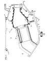
- FIG. 1 is a schematic representation of a combustion section of a gas turbine engine with a secondary fuel nozzle attached to an outer engine case wall and extending through into a combustor wall.
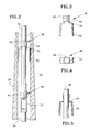
- FIG. 2 is an enlarged, sectional view of the fuel nozzle of the present invention shown in FIG 1 .
- FIG. 3 is a front view of the fuel nozzle vibration damper of the present invention.
- FIG. 4 is a top view of the fuel nozzle vibration damper of the present invention.
- FIG. 5 is a cross-sectional view of the fuel nozzle vibration damp of the present invention mounted on an inner fuel tube.
- a combustor 10 is disposed within an annulus 12 between an inner engine case wall 14 and an outer engine case wall 16 .
- a diffuser 18 leads axially into the annulus 12 from a compression section (not shown).
- a plurality of primary fuel nozzles 20 are spaced circumferentially within the annulus 12 to premix fuel with a portion of air exiting the diffuser 18 and to supply the fuel and air mixture to the combustor 10 .
- a plurality of secondary fuel nozzles 24 are spaced circumferentially within the annulus 12 to provide a fuel-air mixture radially into the combustor 10 .
- Each secondary fuel nozzle 24 is fixedly attached to the outer engine case wall 16 , and extends into the combustor 10 through an annular fuel nozzle guide 30 .
- the fuel nozzle guide 30 is fixedly mounted onto a combustor wall 31 .
- the secondary fuel nozzle 24 has a central axis A f about which is disposed an inner fuel tube 34 which carries liquid fuel.
- the secondary fuel nozzle also includes an outer fuel tube 36 (in the preferred embodiment, an outer housing) disposed about the central axis and spaced radially outwardly from the inner fuel tube 34 .
- the outer fuel tube has an inner surface 37 , and carries gaseous fuel such as natural gas.
- Vibration dampers 38 are attached to the inner fuel tube 34 .
- the damper 38 has an annular portion or sleeve 40 which may be brazed onto the inner fuel tube.
- the vibration damper 38 includes at least two L-shaped legs 42 .
- the legs have a radially extending portion 44 and a longitudinally extending portion 46 .
- the longitudinally extending portion 46 is a spring and thus resilient.
- a second vibration damper 38 is spaced longitudinally from a first damper 38 as shown in FIG. 2 .
- the second damper 38 is angularly offset by ninety degrees (90°) from the first damper.
- the outer engine case 16 and the combustor 10 move relative to each other as a result of thermal cycling.
- the secondary fuel nozzles 24 experience vibratory movement as they are attached to the outer engine case and via the fuel nozzle guide 30 , to the combustor wall 31 .
- the inner fuel tube 34 and the outer fuel tube 36 experience vibratory forces as they too are structurally attached to the outer engine case and to the combustor wall which transmit the vibrational energy to the tubes.
- the inner tube, being unsupported in the fuel nozzle, is susceptible to vibrational damage and any resultant fatigue.
- the vibrational damper of the present invention dampens vibrations between the inner and outer tubes.
- the spring action of the damper 38 applies a constant force against the outer tube. This force not only maintains the concentricity of the inner and outer tubes, but also dampens vibrations between the two tubes.
- the diameter of the damper is sized closely to the diameter of the outer tube to maximize surface contact between the longitudinally extending portions 46 of the legs and the inner surface 37 of the outer tube 36 .
- the fuel tubes are not subjected to wear and fatigue imposed by vibratory forces.
- the vibration damper of the present invention also offers minimal fuel flow blockage in the annulus between the inner and outer fuel tubes.
- the legs of the damper are not circumferentially continuous to impede fuel flow.
- the preferred embodiment of the present invention distributes any blockage to fuel flow in the outer tube, thus decreasing the pressure drop in the outer tube as compared with a configuration that has the dampers aligned.
- the vibration damper of the preferred embodiment offers a low cost, vibration damping mechanism with minimal impact to the flow of fuel in fuel nozzles.
Abstract
Description
- The present invention relates to gas turbine engines and more particularly to a vibration damper that limits vibrational effects between concentric tubes in a fuel nozzle.
- A gas turbine engine combustor is typically disposed within an annular combustion section between an inner and an outer engine case wall. A plurality of primary fuel nozzles disposed in the upstream end of the combustor supply a mixture of fuel and air axially into the combustor at a closely controlled ratio. A plurality of secondary fuel nozzles are disposed in the outer engine case wall. The secondary fuel nozzles supply a mixture of fuel and air radially into the combustor during engine startup and at certain thrust levels. The secondary fuel nozzles are actuated during low and intermediate power regimes to stabilize the flame in the combustor.
- Typically, the secondary fuel nozzles include a central axis about which are disposed an inner and an outer concentric fuel tubes. The inner tube carries liquid fuel while the outer tube carries fuel supplied as a gaseous fluid (natural gas fuel). The gaseous fuel in the outer tube thermally insulates the liquid fuel in the inner tube thereby preventing a problem of coking within the fuel nozzle. Coking is a thickening of any residual fuel that is stagnant within the fuel system passages. When stagnant fuel is heated, it solidifies and can reduce effective fuel flow capacity and actually plug the fuel supply system. The secondary fuel nozzles are particularly susceptible to coking because fuel tends to stagnate and get heated within the nozzle when the nozzle is not actuated during those thrust settings when only the primary nozzles are operating. Thus, insulating the inner tube carrying liquid fuel by the outer concentric tube, reduces the problem of coking.
- However, the geometry of the inner and outer concentric tubes is not without problem. It will be appreciated that the environment within a gas turbine engine combustion chamber is extremely harsh. The fuel-air mixture burns in the combustion chamber at temperatures as high as 2100°C (3800°F) causing extreme thermal gradients and therefore, thermal stresses in the inner and outer engine case walls in the combustion section. Moreover, rotational movement of the engine's compressor and turbine, as well as the high flow rate of the fuel-air mixture and the burning thereof, may cause significant vibration and pressure pulsations in the combustion section and engine case walls. Such high thermal stresses and vibration experienced by the combustion section walls are also experienced by the secondary fuel nozzles. Prior art secondary fuel nozzles have, in large measure, failed to adequately tolerate such a harsh vibratory and thermal environment without themselves exhibiting vibratory movement. Such movement risks not only the misalignment of the fuel nozzles with other components in the combustor such as igniters, and the like, but also actual damage to the concentric fuel tubes of the nozzles due to relative vibratory movement between the inner and outer fuel tubes. The inner and outer fuel tubes may crack due to wear and fatigue caused by the vibratory stresses.
- U.S. Patent Nos. 3,785,407 to Waite et al. and 4,098,476 to Jutte et al. teach an apparatus for a spacer member between a pipe and a cover, and a support apparatus to prevent rotational and translational motion at certain temperatures respectively. While Waite et al. discloses a pipe cover spacer with yieldable fingers extending to make contact with a pipe, it is desirable to dampen vibrations between two tubes in an economical way. The yieldable fingers in Waite's disclosure are separate pieces arranged circumferentially to provide a spacing function. Further, while Jutte et al. discloses a support apparatus that fits loosely around the inner housing, this configuration would not be able to dampen low amplitude vibrations between two concentric tubes. In addition, the support apparatus in Jutte et al. is a circumferentially continuous ring, a configuration which would impede flow in the annulus of the outer tube. Thus, there is a need to provide an economical vibration damping system for two concentric tubes, while maintaining fuel flow in the outer tube.
- The present invention provides a fuel injection nozzle for a gas turbine engine having first and second fuel tubes, the second tube radially outside the first, and a vibration damper. The vibration damper comprises a sleeve engaging one of the tubes, and at least two legs engaging the other tube. Each leg has a radial portion extending from the sleeve and a resilient, longitudinally extending portion bearing against a surface of the other tube to dampen vibrational effects between the tubes during engine operation.
- According to one embodiment of the present invention, a fuel nozzle having a central axis, an inner and an outer concentric fuel tube disposed about the axis, is provided with a vibration damper having a sleeve and at least two legs, each leg having a longitudinally extending portion, the sleeve engaging the inner tube and the longitudinally extending portion of the legs bearing against the inner surface of the outer tube wherein the vibration damper dampens vibrational effects between the concentric fuel tubes during engine operation. The legs of the damper are L-shaped, with radially extending portions and resilient longitudinally extending portions.
- In accordance with a preferred embodiment of the present invention, the fuel nozzle includes two vibration dampers at spaced locations. The second damper is angularly offset from the first damper.
- An advantage of the present invention, at least in its preferred embodiments, is the durability and structural integrity of the fuel nozzles due to the vibration damper. The vibration damper appreciably reduces the intensity of vibratory forces experienced by the concentric tubes. The fuel tubes are thus not subject to wear and fatigue imposed by the vibration forces. Another advantage of preferred embodiments of the present invention is minimal fuel flow blockage in the annulus between the inner and outer tube. By angularly offsetting the dampers, the present invention distributes any blockage to the fuel flow in the outer tube. This decreases the pressure drop in the outer tube as compared with a configuration that has the dampers aligned. Further, the legs minimally block fuel flow because they are not circumferentially continuous.
- A preferred embodiment of the invention will now be described by way of example only and with reference to the accompanying drawings, in which:
- FIG. 1 is a schematic representation of a combustion section of a gas turbine engine with a secondary fuel nozzle attached to an outer engine case wall and extending through into a combustor wall.
- FIG. 2 is an enlarged, sectional view of the fuel nozzle of the present invention shown in FIG 1.
- FIG. 3 is a front view of the fuel nozzle vibration damper of the present invention.
- FIG. 4 is a top view of the fuel nozzle vibration damper of the present invention.
- FIG. 5 is a cross-sectional view of the fuel nozzle vibration damp of the present invention mounted on an inner fuel tube.
- Referring to FIG. 1, a
combustor 10 is disposed within anannulus 12 between an innerengine case wall 14 and an outerengine case wall 16. Adiffuser 18 leads axially into theannulus 12 from a compression section (not shown). A plurality ofprimary fuel nozzles 20 are spaced circumferentially within theannulus 12 to premix fuel with a portion of air exiting thediffuser 18 and to supply the fuel and air mixture to thecombustor 10. - A plurality of
secondary fuel nozzles 24 are spaced circumferentially within theannulus 12 to provide a fuel-air mixture radially into thecombustor 10. Eachsecondary fuel nozzle 24 is fixedly attached to the outerengine case wall 16, and extends into thecombustor 10 through an annularfuel nozzle guide 30. Thefuel nozzle guide 30 is fixedly mounted onto acombustor wall 31. - Referring to FIGS. 2, 3, 4 and 5, the
secondary fuel nozzle 24 has a central axis Af about which is disposed aninner fuel tube 34 which carries liquid fuel. The secondary fuel nozzle also includes an outer fuel tube 36 (in the preferred embodiment, an outer housing) disposed about the central axis and spaced radially outwardly from theinner fuel tube 34. The outer fuel tube has aninner surface 37, and carries gaseous fuel such as natural gas.Vibration dampers 38 are attached to theinner fuel tube 34. Thedamper 38 has an annular portion orsleeve 40 which may be brazed onto the inner fuel tube. - The
vibration damper 38 includes at least two L-shaped legs 42. The legs have a radially extendingportion 44 and a longitudinally extendingportion 46. The longitudinally extendingportion 46 is a spring and thus resilient. - In an embodiment of the present invention, a
second vibration damper 38 is spaced longitudinally from afirst damper 38 as shown in FIG. 2. Thesecond damper 38 is angularly offset by ninety degrees (90°) from the first damper. - During the operation of the engine, the
outer engine case 16 and thecombustor 10 move relative to each other as a result of thermal cycling. Thesecondary fuel nozzles 24 experience vibratory movement as they are attached to the outer engine case and via thefuel nozzle guide 30, to thecombustor wall 31. In turn, theinner fuel tube 34 and theouter fuel tube 36 experience vibratory forces as they too are structurally attached to the outer engine case and to the combustor wall which transmit the vibrational energy to the tubes. The inner tube, being unsupported in the fuel nozzle, is susceptible to vibrational damage and any resultant fatigue. The vibrational damper of the present invention dampens vibrations between the inner and outer tubes. The spring action of thedamper 38, in particular that of thelongitudinally extending portions 46, applies a constant force against the outer tube. This force not only maintains the concentricity of the inner and outer tubes, but also dampens vibrations between the two tubes. The diameter of the damper is sized closely to the diameter of the outer tube to maximize surface contact between the longitudinally extendingportions 46 of the legs and theinner surface 37 of theouter tube 36. Thus, the fuel tubes are not subjected to wear and fatigue imposed by vibratory forces. - The vibration damper of the present invention also offers minimal fuel flow blockage in the annulus between the inner and outer fuel tubes. The legs of the damper are not circumferentially continuous to impede fuel flow. In addition, by longitudinally spacing the dampers in the fuel tubes and by angularly offsetting the legs, the preferred embodiment of the present invention distributes any blockage to fuel flow in the outer tube, thus decreasing the pressure drop in the outer tube as compared with a configuration that has the dampers aligned. Thus, the vibration damper of the preferred embodiment offers a low cost, vibration damping mechanism with minimal impact to the flow of fuel in fuel nozzles.
- Although the invention has been shown and described with respect to detailed embodiments thereof, it should be understood by those skilled in the art that various changes in form and detail thereof may be made without departing from the scope of the claimed invention.
Claims (9)
- A fuel injection nozzle (24) for a gas turbine engine having a longitudinal axis, a first fuel tube (34), a second fuel tube (36) positioned radially outwardly from said first tube, and a vibration damper (38), said damper (38) comprising:a sleeve (40) engaging one of the fuel tubes (34); andat least two legs (42), engaging the other of said fuel tubes (36), each leg having a radial portion (44) extending from said sleeve and a resilient, longitudinally extending portion (46) bearing against a surface (37) of the other fuel tube to dampen vibrational effects between said first and second fuel tubes during engine operation.
- The fuel injection nozzle of claim 1, wherein the sleeve (40) of said vibration damper (38) engages the first fuel tube (34) and the longitudinally extending portion (46) of each said leg (42) bears against the inner surface (37) of the second fuel tube (36).
- The fuel injection nozzle of claim 1 or 2, wherein the radial (44) and longitudinal (46) portions of said legs (42) are substantially perpendicular with respect to one another.
- The fuel injection nozzle of claim 1, 2 or 3, wherein a second vibration damper (38) is spaced longitudinally from a first damper (38).
- The fuel injection nozzle of claim 4, wherein the second vibration damper (38) is angularly offset from the first damper (38).
- The fuel injection nozzle of claim 4 or 5, wherein the second damper (38) is offset approximately ninety degrees from the first damper (38).
- A vibration damping system having a first tube (34), a second tube (36) positioned radially outwardly from said first tube, and a vibration damper (38) comprising:a sleeve (40) engaging one of the tubes (34); andat least two legs (42) engaging the other said tube (38), each leg having a radial portion (44) extending from said sleeve and a resilient, longitudinally extending portion (46) bearing against a surface (37) of the other tube to dampen vibrational effects between said first and second tubes.
- The vibration damping system of claim 7, wherein the radial (44) and longitudinal (46) portions of said legs (42) are substantially perpendicular with respect to one another.
- A vibration damper (38) for a fuel injection nozzle (24) for a gas turbine engine, said fuel injection nozzle comprising a first fuel tube (34), a second fuel tube (36) positioned radially outwardly of said first fuel tube, said vibration damper (38) comprising:a sleeve (40) adapted to engage with one of the fuel tubes (34); andat least two legs (42), adapted to engage the other of said fuel tubes (36), each leg having a radial portion (44) extending from said sleeve and a resilient portion (46) adapted to bear against a surface of the other fuel tube to dampen vibrational effects between said first and second fuel tubes during engine operation.
Applications Claiming Priority (2)
| Application Number | Priority Date | Filing Date | Title |
|---|---|---|---|
| US08/996,631 US6038862A (en) | 1997-12-23 | 1997-12-23 | Vibration damper for a fuel nozzle of a gas turbine engine |
| US996631 | 2001-11-28 |
Publications (3)
| Publication Number | Publication Date |
|---|---|
| EP0926436A2 true EP0926436A2 (en) | 1999-06-30 |
| EP0926436A3 EP0926436A3 (en) | 1999-12-08 |
| EP0926436B1 EP0926436B1 (en) | 2004-08-18 |
Family
ID=25543126
Family Applications (1)
| Application Number | Title | Priority Date | Filing Date |
|---|---|---|---|
| EP98308911A Expired - Lifetime EP0926436B1 (en) | 1997-12-23 | 1998-10-30 | Vibration damper |
Country Status (4)
| Country | Link |
|---|---|
| US (1) | US6038862A (en) |
| EP (1) | EP0926436B1 (en) |
| JP (1) | JPH11241823A (en) |
| DE (1) | DE69825715T2 (en) |
Cited By (1)
| Publication number | Priority date | Publication date | Assignee | Title |
|---|---|---|---|---|
| FR3021090A1 (en) * | 2014-05-14 | 2015-11-20 | Airbus Operations Sas | SYSTEM OF TWO CONCENTRIC PIPES HAVING A CONTACT MEANS TO ENSURE ELECTRICAL CONTINUITY BETWEEN THE TWO PIPES |
Families Citing this family (16)
| Publication number | Priority date | Publication date | Assignee | Title |
|---|---|---|---|---|
| ITMI20012784A1 (en) * | 2001-12-21 | 2003-06-21 | Nuovo Pignone Spa | IMPROVED LIQUID FUEL INJECTOR FOR GAS TURBINE BURNERS |
| US6886346B2 (en) * | 2003-08-20 | 2005-05-03 | Power Systems Mfg., Llc | Gas turbine fuel pilot nozzle |
| US7197877B2 (en) * | 2004-08-04 | 2007-04-03 | Siemens Power Generation, Inc. | Support system for a pilot nozzle of a turbine engine |
| US7921649B2 (en) * | 2005-07-21 | 2011-04-12 | Parker-Hannifin Corporation | Mode suppression shape for beams |
| US8312727B2 (en) * | 2006-09-26 | 2012-11-20 | Parker-Hannifin Corporation | Vibration damper |
| US8308076B2 (en) | 2009-02-20 | 2012-11-13 | Pratt & Whitney Canada Corp. | Nozzle design to reduce fretting |
| US8042752B2 (en) * | 2009-02-20 | 2011-10-25 | Pratt & Whitney Canada Corp. | Nozzle repair to reduce fretting |
| US9021675B2 (en) | 2011-08-15 | 2015-05-05 | United Technologies Corporation | Method for repairing fuel nozzle guides for gas turbine engine combustors using cold metal transfer weld technology |
| US9194251B2 (en) | 2012-08-10 | 2015-11-24 | United Technologies Corporation | Duct damper |
| WO2015103751A1 (en) * | 2014-01-09 | 2015-07-16 | General Electric Company | Vibration damping assembly for a piping unit |
| US10934890B2 (en) * | 2014-05-09 | 2021-03-02 | Raytheon Technologies Corporation | Shrouded conduit for arranging a fluid flowpath |
| US9915480B2 (en) | 2014-07-03 | 2018-03-13 | United Technologies Corporation | Tube assembly |
| US10577973B2 (en) | 2016-02-18 | 2020-03-03 | General Electric Company | Service tube for a turbine engine |
| US10808874B2 (en) | 2017-11-30 | 2020-10-20 | General Electric Company | Inline fluid damper device |
| CN110726158B (en) * | 2018-07-17 | 2021-04-23 | 中国航发商用航空发动机有限责任公司 | Fuel nozzle structure of aircraft engine |
| US11473431B2 (en) * | 2019-03-12 | 2022-10-18 | Raytheon Technologies Corporation | Energy dissipating damper |
Citations (2)
| Publication number | Priority date | Publication date | Assignee | Title |
|---|---|---|---|---|
| US3785407A (en) | 1970-05-25 | 1974-01-15 | Transco Inc | Pipe cover spacer and diameter compensator |
| US4098476A (en) | 1977-06-07 | 1978-07-04 | The United States Of America As Represented By The Secretary Of The Army | Mechanical support |
Family Cites Families (18)
| Publication number | Priority date | Publication date | Assignee | Title |
|---|---|---|---|---|
| US3126918A (en) * | 1964-03-31 | Slip ring spacer for insulated conduit systems | ||
| US3420553A (en) * | 1966-02-09 | 1969-01-07 | Calumet & Hecla | Apparatus for absorbing sound and vibration in a piping system |
| US3648734A (en) * | 1970-05-25 | 1972-03-14 | Transco Inc | Pipe cover spacer and diameter compensator |
| US4033381A (en) * | 1975-06-27 | 1977-07-05 | General Connectors Corporation | Hot air duct |
| US4258544A (en) * | 1978-09-15 | 1981-03-31 | Caterpillar Tractor Co. | Dual fluid fuel nozzle |
| US4250927A (en) * | 1979-08-24 | 1981-02-17 | Piper Aircraft Corporation | Duct spacer clip and duct assembly |
| FR2470915A1 (en) * | 1979-12-03 | 1981-06-12 | Snecma | PIPE PROTECTION DEVICE SUCH AS AN ELECTRICAL CONDUCTOR, ITS MANUFACTURING METHOD AND PIPE PROVIDED WITH SUCH DEVICE |
| US4350372A (en) * | 1980-01-21 | 1982-09-21 | Logsdon Duane D | Expansion coupling for large diameter plastic pipes |
| DE3017574C2 (en) * | 1980-05-08 | 1985-06-05 | Wieland-Werke Ag, 7900 Ulm | Spacers for coaxial heat exchangers |
| US4467610A (en) * | 1981-04-17 | 1984-08-28 | General Electric Company | Gas turbine fuel system |
| US4436119A (en) * | 1982-09-24 | 1984-03-13 | Shahan James E | Thermal acoustical pipe insulation |
| DE8807095U1 (en) * | 1988-05-31 | 1988-07-21 | Kunststofftechnik Kg, 5210 Troisdorf, De | |
| US5201887A (en) * | 1991-11-26 | 1993-04-13 | United Technologies Corporation | Damper for augmentor liners |
| IT1263683B (en) * | 1992-08-21 | 1996-08-27 | Westinghouse Electric Corp | NOZZLE COMPLEX FOR FUEL FOR A GAS TURBINE |
| US5423178A (en) * | 1992-09-28 | 1995-06-13 | Parker-Hannifin Corporation | Multiple passage cooling circuit method and device for gas turbine engine fuel nozzle |
| US5497809A (en) * | 1994-01-05 | 1996-03-12 | Wolf; Lawrence W. | Vented bending sleeves for coaxial tubing systems |
| US5370427A (en) * | 1994-01-10 | 1994-12-06 | General Electric Company | Expansion joint for fluid piping with rotation prevention member |
| DE29502944U1 (en) * | 1995-02-22 | 1995-05-11 | Elco Energiesysteme Ag | Oil burner |
-
1997
- 1997-12-23 US US08/996,631 patent/US6038862A/en not_active Expired - Lifetime
-
1998
- 1998-10-30 DE DE1998625715 patent/DE69825715T2/en not_active Expired - Lifetime
- 1998-10-30 EP EP98308911A patent/EP0926436B1/en not_active Expired - Lifetime
- 1998-12-08 JP JP10347686A patent/JPH11241823A/en active Pending
Patent Citations (2)
| Publication number | Priority date | Publication date | Assignee | Title |
|---|---|---|---|---|
| US3785407A (en) | 1970-05-25 | 1974-01-15 | Transco Inc | Pipe cover spacer and diameter compensator |
| US4098476A (en) | 1977-06-07 | 1978-07-04 | The United States Of America As Represented By The Secretary Of The Army | Mechanical support |
Cited By (1)
| Publication number | Priority date | Publication date | Assignee | Title |
|---|---|---|---|---|
| FR3021090A1 (en) * | 2014-05-14 | 2015-11-20 | Airbus Operations Sas | SYSTEM OF TWO CONCENTRIC PIPES HAVING A CONTACT MEANS TO ENSURE ELECTRICAL CONTINUITY BETWEEN THE TWO PIPES |
Also Published As
| Publication number | Publication date |
|---|---|
| DE69825715D1 (en) | 2004-09-23 |
| EP0926436B1 (en) | 2004-08-18 |
| US6038862A (en) | 2000-03-21 |
| JPH11241823A (en) | 1999-09-07 |
| EP0926436A3 (en) | 1999-12-08 |
| DE69825715T2 (en) | 2005-01-13 |
Similar Documents
| Publication | Publication Date | Title |
|---|---|---|
| US6038862A (en) | Vibration damper for a fuel nozzle of a gas turbine engine | |
| CA1188900A (en) | Self-aligning fuel nozzle assembly | |
| US8375726B2 (en) | Combustor assembly in a gas turbine engine | |
| US9010119B2 (en) | Premixing nozzle | |
| CA2478606C (en) | Fixing system of a flame pipe or liner | |
| JP6243621B2 (en) | Acoustic resonator located in the flow sleeve of a gas turbine combustor | |
| JP2006510865A (en) | Combustor low cost floating collar with improved sealing and damping effects | |
| US8327649B2 (en) | Gas turbine fuel injector assembly with overlapping frictionally engaged members for damping vibrations | |
| US20040040307A1 (en) | Methods and apparatus for operating gas turbine engines | |
| CN109073221B (en) | High frequency acoustic damper for combustor liner | |
| JP7019367B2 (en) | Tools and methods for separating flame propagation tube assemblies in gas turbine engines | |
| KR102019091B1 (en) | Fuel nozzle assembly, combustor and gas turbine having the same | |
| US11333361B2 (en) | Combustor liner flexible support and method | |
| JP7352604B2 (en) | Burner and combustor | |
| EP2672184A2 (en) | Method and apparatus for a fuel nozzle assembly for use with a combustor | |
| US10808788B2 (en) | Damper for a fuel delivery system | |
| JP2014001920A (en) | Cross-fire tube holding system for gas-turbine engine | |
| KR102063623B1 (en) | Structure of gas turbine combustion nozzle for improving a dynamic characteristics | |
| KR102126810B1 (en) | Mounting structure of gas turbine combustion nozzle for improving a vibration characteristics | |
| CN110887060A (en) | Flame propagation tube, combustor and gas turbine comprising same |
Legal Events
| Date | Code | Title | Description |
|---|---|---|---|
| PUAI | Public reference made under article 153(3) epc to a published international application that has entered the european phase |
Free format text: ORIGINAL CODE: 0009012 |
|
| AK | Designated contracting states |
Kind code of ref document: A2 Designated state(s): DE FR GB |
|
| AX | Request for extension of the european patent |
Free format text: AL;LT;LV;MK;RO;SI |
|
| PUAL | Search report despatched |
Free format text: ORIGINAL CODE: 0009013 |
|
| AK | Designated contracting states |
Kind code of ref document: A3 Designated state(s): AT BE CH CY DE DK ES FI FR GB GR IE IT LI LU MC NL PT SE |
|
| AX | Request for extension of the european patent |
Free format text: AL;LT;LV;MK;RO;SI |
|
| 17P | Request for examination filed |
Effective date: 20000221 |
|
| AKX | Designation fees paid |
Free format text: DE FR GB |
|
| 17Q | First examination report despatched |
Effective date: 20011018 |
|
| GRAP | Despatch of communication of intention to grant a patent |
Free format text: ORIGINAL CODE: EPIDOSNIGR1 |
|
| GRAS | Grant fee paid |
Free format text: ORIGINAL CODE: EPIDOSNIGR3 |
|
| GRAA | (expected) grant |
Free format text: ORIGINAL CODE: 0009210 |
|
| AK | Designated contracting states |
Kind code of ref document: B1 Designated state(s): DE FR GB |
|
| REG | Reference to a national code |
Ref country code: GB Ref legal event code: FG4D |
|
| REF | Corresponds to: |
Ref document number: 69825715 Country of ref document: DE Date of ref document: 20040923 Kind code of ref document: P |
|
| ET | Fr: translation filed | ||
| PLBE | No opposition filed within time limit |
Free format text: ORIGINAL CODE: 0009261 |
|
| STAA | Information on the status of an ep patent application or granted ep patent |
Free format text: STATUS: NO OPPOSITION FILED WITHIN TIME LIMIT |
|
| 26N | No opposition filed |
Effective date: 20050519 |
|
| PGFP | Annual fee paid to national office [announced via postgrant information from national office to epo] |
Ref country code: FR Payment date: 20081006 Year of fee payment: 11 |
|
| REG | Reference to a national code |
Ref country code: FR Ref legal event code: ST Effective date: 20100630 |
|
| PG25 | Lapsed in a contracting state [announced via postgrant information from national office to epo] |
Ref country code: FR Free format text: LAPSE BECAUSE OF NON-PAYMENT OF DUE FEES Effective date: 20091102 |
|
| PGFP | Annual fee paid to national office [announced via postgrant information from national office to epo] |
Ref country code: DE Payment date: 20131023 Year of fee payment: 16 |
|
| REG | Reference to a national code |
Ref country code: DE Ref legal event code: R119 Ref document number: 69825715 Country of ref document: DE |
|
| PG25 | Lapsed in a contracting state [announced via postgrant information from national office to epo] |
Ref country code: DE Free format text: LAPSE BECAUSE OF NON-PAYMENT OF DUE FEES Effective date: 20150501 |
|
| PGFP | Annual fee paid to national office [announced via postgrant information from national office to epo] |
Ref country code: GB Payment date: 20160928 Year of fee payment: 19 |
|
| GBPC | Gb: european patent ceased through non-payment of renewal fee |
Effective date: 20171030 |
|
| PG25 | Lapsed in a contracting state [announced via postgrant information from national office to epo] |
Ref country code: GB Free format text: LAPSE BECAUSE OF NON-PAYMENT OF DUE FEES Effective date: 20171030 |