EP0928012B1 - Optical proximity correction method and apparatus - Google Patents
Optical proximity correction method and apparatus Download PDFInfo
- Publication number
- EP0928012B1 EP0928012B1 EP98106429A EP98106429A EP0928012B1 EP 0928012 B1 EP0928012 B1 EP 0928012B1 EP 98106429 A EP98106429 A EP 98106429A EP 98106429 A EP98106429 A EP 98106429A EP 0928012 B1 EP0928012 B1 EP 0928012B1
- Authority
- EP
- European Patent Office
- Prior art keywords
- features
- correction
- layout design
- design
- recited
- Prior art date
- Legal status (The legal status is an assumption and is not a legal conclusion. Google has not performed a legal analysis and makes no representation as to the accuracy of the status listed.)
- Expired - Lifetime
Links
Images


Classifications
-
- G—PHYSICS
- G03—PHOTOGRAPHY; CINEMATOGRAPHY; ANALOGOUS TECHNIQUES USING WAVES OTHER THAN OPTICAL WAVES; ELECTROGRAPHY; HOLOGRAPHY
- G03F—PHOTOMECHANICAL PRODUCTION OF TEXTURED OR PATTERNED SURFACES, e.g. FOR PRINTING, FOR PROCESSING OF SEMICONDUCTOR DEVICES; MATERIALS THEREFOR; ORIGINALS THEREFOR; APPARATUS SPECIALLY ADAPTED THEREFOR
- G03F7/00—Photomechanical, e.g. photolithographic, production of textured or patterned surfaces, e.g. printing surfaces; Materials therefor, e.g. comprising photoresists; Apparatus specially adapted therefor
- G03F7/70—Microphotolithographic exposure; Apparatus therefor
- G03F7/70425—Imaging strategies, e.g. for increasing throughput or resolution, printing product fields larger than the image field or compensating lithography- or non-lithography errors, e.g. proximity correction, mix-and-match, stitching or double patterning
- G03F7/70433—Layout for increasing efficiency or for compensating imaging errors, e.g. layout of exposure fields for reducing focus errors; Use of mask features for increasing efficiency or for compensating imaging errors
- G03F7/70441—Optical proximity correction [OPC]
-
- G—PHYSICS
- G03—PHOTOGRAPHY; CINEMATOGRAPHY; ANALOGOUS TECHNIQUES USING WAVES OTHER THAN OPTICAL WAVES; ELECTROGRAPHY; HOLOGRAPHY
- G03F—PHOTOMECHANICAL PRODUCTION OF TEXTURED OR PATTERNED SURFACES, e.g. FOR PRINTING, FOR PROCESSING OF SEMICONDUCTOR DEVICES; MATERIALS THEREFOR; ORIGINALS THEREFOR; APPARATUS SPECIALLY ADAPTED THEREFOR
- G03F1/00—Originals for photomechanical production of textured or patterned surfaces, e.g., masks, photo-masks, reticles; Mask blanks or pellicles therefor; Containers specially adapted therefor; Preparation thereof
- G03F1/36—Masks having proximity correction features; Preparation thereof, e.g. optical proximity correction [OPC] design processes
-
- H—ELECTRICITY
- H01—ELECTRIC ELEMENTS
- H01J—ELECTRIC DISCHARGE TUBES OR DISCHARGE LAMPS
- H01J37/00—Discharge tubes with provision for introducing objects or material to be exposed to the discharge, e.g. for the purpose of examination or processing thereof
- H01J37/30—Electron-beam or ion-beam tubes for localised treatment of objects
- H01J37/302—Controlling tubes by external information, e.g. programme control
- H01J37/3023—Programme control
-
- H—ELECTRICITY
- H01—ELECTRIC ELEMENTS
- H01J—ELECTRIC DISCHARGE TUBES OR DISCHARGE LAMPS
- H01J2237/00—Discharge tubes exposing object to beam, e.g. for analysis treatment, etching, imaging
- H01J2237/30—Electron or ion beam tubes for processing objects
- H01J2237/317—Processing objects on a microscale
- H01J2237/3175—Lithography
- H01J2237/31769—Proximity effect correction
Description
Claims (21)
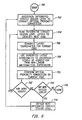
- A method for correcting a layout design using a design rule checker, comprising:providing (902) a layout design file having the layout design that is to be corrected for optical proximity by the design rule checker; characterized byproviding (906, 908) a run set (850) to the design rule checker, the run set includes a plurality of correction values that are used to correct a plurality of features (802-808) of the layout design that have a selected space dimension;identifying (920-924) each of the plurality of features (802-808) that have the selected space dimension; andcorrecting (926) each of the plurality of features that have the selected space dimension with one correction value of the plurality of correction values of the run set (850).
- A method for correcting a layout design using a design rule checker as recited in claim 1, wherein the run set (850) is generated from a correction table that has the plurality of correction values.
- A method for correcting a layout design using a design rule checker as recited in claim 2, wherein the correcting (926) of each of the plurality of features (802-808) that have the selected space dimension is performed on edges of the plurality of features, and the edges of at least two of the plurality of features define the selected space dimension.
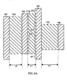
- A method for correcting a layout design using a design rule checker as recited in claim 1, wherein the correcting (926) of each of the plurality of features (802-808) further includes:perform (930) an oversize operation on each of the plurality of features that have the selected space dimension, the oversize operation being configured to define an oversize perimeter that extends a size of each of the plurality of features by a correction value that corresponds to the selected space dimension, and an oversized area is defined between an outline of each of the plurality of features and the oversize perimeter.
- A method for correcting a layout design using a design rule checker as recited in claim 4, wherein the correcting (926) of each of the plurality of features (802-808) further includes:performing (932) a boolean AND operation between the oversized area and a space area that lies between each of the plurality of features that have the selected space dimension, the boolean AND operation thereby producing an AND result.
- A method for correcting a layout design using a design rule checker as recited in claim 5, wherein the correcting (926) of each of the plurality of features (802-808) further includes:performing (934) a boolean OR operation for each of the plurality of features that have the selected space dimension and the AND result.
- A method for correcting a layout design using a design rule checker as recited in claim 6, wherein the boolean OR operation (934) produces a plurality of corrected features, and the plurality of corrected features are the plurality of features that were identified to have the selected space dimension.
- A method for correcting a layout design using a design rule checker as recited in claim 1, wherein the identifying (920-924) of each of the plurality of features (802-808) that have the selected space dimension is repeated for other selected space dimensions.
- A method according to claim 1, wherein said selected space dimension is a particular width from the layout design file, said identified features (802-808) have a predetermined inter-feature spacing, the inter-feature spacing being defined by edges of the selected set of features, and the correction being performed on the edges of the identified features.
- A method as recited in claim 9, wherein the identifying and correcting are repeated for one or more identified features having different inter-feature spacings.
- A method as recited in claim 10, wherein the correction value is derived from the non-linear curve and is part of a correction value table, and a particular correction value is associated with the different inter-feature spacings.
- A method as recited in claim 9, wherein correcting the identified features includes performing a set of logical operations.
- A method as recited in claim 12, wherein the set of logical operations include:performing an oversize operation on the selected set of features to produce an oversize outline, the oversize operation being configured to increase the size of the selected set of features by an amount that is equivalent to the correction that is the value derived from the non-linear correction curve.
- A method as recited in claim 13, wherein the set of logical operations include:performing a boolean AND operation between an area defined between the identified features and the oversize outline, and an area that lies between the edges of the identified features, the boolean AND operation thereby producing a set of correction areas.
- A method as recited in claim 14, wherein the set of logical operations include:producing a set of corrected features that include an area of the identified features and the set of correction areas.
- An apparatus adapted to correct a layout design for optical proximity correction errors, comprising:wherein the design rule checker continues to iteratively correct the layout design until a predetermined number of sets of features are corrected;a design layout file containing the layout design; anda design rule checker adapted to iteratively correct the layout design, such that a set of features (802-808) having a selected inter-feature spacing are corrected before a next set of features having another selected inter-feature spacing;
wherein the design rule checker comprises a run set (850), the run set includes.a plurality of correction values that are used to correct said set of features (802-808) of the layout design that have said selected inter-feature spacing; and
wherein the design rule checker is adapted to correct (926) said set of features that have the selected inter-feature spacing with one correction value of the plurality of correction values of the run set (850). - An apparatus adapted to correct a layout design for optical proximity correction errors as recited in claim 16, wherein each of the predetermined number of sets of features are associated with a particular correction value.
- An apparatus adapted to correct a layout design for optical proximity correction errors as recited in claim 17, wherein the particular correction value is derived from a non-linear curve, and the particular correction value is adjusted to a closest grid increment of the layout design.
- An apparatus adapted to correct a layout design for optical proximity correction errors as recited in claim 18, wherein the design rule checker is adapted to implement the particular correction value to perform a series of boolean operations to complete one of the iterative corrections of the layout design.
- An apparatus adapted to correct a layout design for optical proximity correction errors as recited in claim 19, wherein the one of the iterative corrections are configured to correct a pair of edges of the set of features and the next set of features, and the pair of edges bound the selected inter-feature spacing and the another selected inter-feature spacing.
- An apparatus adapted to correct a layout design for optical proximity correction errors as recited in claim 20, wherein the pair of edges are corrected by an amount equal to the particular correction value.
Applications Claiming Priority (2)
| Application Number | Priority Date | Filing Date | Title |
|---|---|---|---|
| US08/991,785 US6269472B1 (en) | 1996-02-27 | 1997-12-12 | Optical proximity correction method and apparatus |
| US991785 | 1997-12-12 |
Publications (3)
| Publication Number | Publication Date |
|---|---|
| EP0928012A2 EP0928012A2 (en) | 1999-07-07 |
| EP0928012A3 EP0928012A3 (en) | 1999-07-14 |
| EP0928012B1 true EP0928012B1 (en) | 2005-07-06 |
Family
ID=25537563
Family Applications (1)
| Application Number | Title | Priority Date | Filing Date |
|---|---|---|---|
| EP98106429A Expired - Lifetime EP0928012B1 (en) | 1997-12-12 | 1998-04-08 | Optical proximity correction method and apparatus |
Country Status (4)
| Country | Link |
|---|---|
| US (1) | US6269472B1 (en) |
| EP (1) | EP0928012B1 (en) |
| JP (1) | JP3001855B2 (en) |
| DE (1) | DE69830782T2 (en) |
Families Citing this family (105)
| Publication number | Priority date | Publication date | Assignee | Title |
|---|---|---|---|---|
| US6470489B1 (en) * | 1997-09-17 | 2002-10-22 | Numerical Technologies, Inc. | Design rule checking system and method |
| US6467076B1 (en) * | 1999-04-30 | 2002-10-15 | Nicolas Bailey Cobb | Method and apparatus for submicron IC design |
| US6301697B1 (en) * | 1999-04-30 | 2001-10-09 | Nicolas B. Cobb | Streamlined IC mask layout optical and process correction through correction reuse |
| US6643616B1 (en) * | 1999-12-07 | 2003-11-04 | Yuri Granik | Integrated device structure prediction based on model curvature |
| US6421820B1 (en) * | 1999-12-13 | 2002-07-16 | Infineon Technologies Ag | Semiconductor device fabrication using a photomask with assist features |
| US6584609B1 (en) * | 2000-02-28 | 2003-06-24 | Numerical Technologies, Inc. | Method and apparatus for mixed-mode optical proximity correction |
| US7412676B2 (en) * | 2000-06-13 | 2008-08-12 | Nicolas B Cobb | Integrated OPC verification tool |
| US6425113B1 (en) * | 2000-06-13 | 2002-07-23 | Leigh C. Anderson | Integrated verification and manufacturability tool |
| US6430737B1 (en) | 2000-07-10 | 2002-08-06 | Mentor Graphics Corp. | Convergence technique for model-based optical and process correction |
| US6523162B1 (en) | 2000-08-02 | 2003-02-18 | Numerical Technologies, Inc. | General purpose shape-based layout processing scheme for IC layout modifications |
| US6557162B1 (en) * | 2000-09-29 | 2003-04-29 | Numerical Technologies, Inc. | Method for high yield reticle formation |
| US6598218B2 (en) * | 2000-12-19 | 2003-07-22 | United Microelectronics Corp. | Optical proximity correction method |
| US6553559B2 (en) * | 2001-01-05 | 2003-04-22 | International Business Machines Corporation | Method to determine optical proximity correction and assist feature rules which account for variations in mask dimensions |
| US6574784B1 (en) * | 2001-06-14 | 2003-06-03 | George P. Lippincott | Short edge management in rule based OPC |
| TW569295B (en) * | 2001-09-29 | 2004-01-01 | Toshiba Corp | Producing method for mask pattern and manufacturing method for semiconductor device |
| US7159197B2 (en) * | 2001-12-31 | 2007-01-02 | Synopsys, Inc. | Shape-based geometry engine to perform smoothing and other layout beautification operations |
| US7013439B2 (en) * | 2002-01-31 | 2006-03-14 | Juan Andres Torres Robles | Contrast based resolution enhancing technology |
| US7293249B2 (en) * | 2002-01-31 | 2007-11-06 | Juan Andres Torres Robles | Contrast based resolution enhancement for photolithographic processing |
| US6670646B2 (en) | 2002-02-11 | 2003-12-30 | Infineon Technologies Ag | Mask and method for patterning a semiconductor wafer |
| US7035446B2 (en) | 2002-05-22 | 2006-04-25 | Lsi Logic Corporation | Quality measurement of an aerial image |
| US6973633B2 (en) * | 2002-07-24 | 2005-12-06 | George Lippincott | Caching of lithography and etch simulation results |
| US6934928B2 (en) * | 2002-08-27 | 2005-08-23 | Micron Technology, Inc. | Method and apparatus for designing a pattern on a semiconductor surface |
| US6898779B2 (en) * | 2002-08-28 | 2005-05-24 | Micron Technology, Inc. | Pattern generation on a semiconductor surface |
| TWI274969B (en) * | 2002-09-11 | 2007-03-01 | Asml Masktools Bv | Method and computer program product of generating masks and mask generated thereby, device manufacturing method and device manufactured thereby, and method of printing pattern |
| US7172838B2 (en) * | 2002-09-27 | 2007-02-06 | Wilhelm Maurer | Chromeless phase mask layout generation |
| US6857109B2 (en) * | 2002-10-18 | 2005-02-15 | George P. Lippincott | Short edge smoothing for enhanced scatter bar placement |
| US6928634B2 (en) * | 2003-01-02 | 2005-08-09 | Yuri Granik | Matrix optical process correction |
| US6747306B1 (en) | 2003-02-04 | 2004-06-08 | International Business Machines Corporation | Vertical gate conductor with buried contact layer for increased contact landing area |
| CN100447795C (en) * | 2003-04-10 | 2008-12-31 | 斯欧普迪克尔股份有限公司 | Method of using a manhattan layout to realize non-manhatton shaped optical structures |
| US7000207B2 (en) * | 2003-04-10 | 2006-02-14 | Sioptical, Inc. | Method of using a Manhattan layout to realize non-Manhattan shaped optical structures |
| US7010764B2 (en) * | 2003-04-14 | 2006-03-07 | Takumi Technology Corp. | Effective proximity effect correction methodology |
| US6973637B2 (en) * | 2003-05-12 | 2005-12-06 | Agere Systems Inc. | Process for the selective control of feature size in lithographic processing |
| US7318214B1 (en) | 2003-06-19 | 2008-01-08 | Invarium, Inc. | System and method for reducing patterning variability in integrated circuit manufacturing through mask layout corrections |
| US6958541B2 (en) * | 2003-07-25 | 2005-10-25 | Lsi Logic Corporation | Low gate resistance layout procedure for RF transistor devices |
| US7100134B2 (en) * | 2003-08-18 | 2006-08-29 | Aprio Technologies, Inc. | Method and platform for integrated physical verifications and manufacturing enhancements |
| US7275227B1 (en) * | 2003-08-27 | 2007-09-25 | Anchor Semiconductor Inc. | Method of checking optical proximity correction data |
| US7073162B2 (en) * | 2003-10-31 | 2006-07-04 | Mentor Graphics Corporation | Site control for OPC |
| US6988260B2 (en) * | 2003-12-18 | 2006-01-17 | Lsi Logic Corporation | Method and apparatus for optimizing fragmentation of boundaries for optical proximity correction (OPC) purposes |
| US7039896B2 (en) | 2003-12-18 | 2006-05-02 | Lsi Logic Corporation | Gradient method of mask edge correction |
| US7539954B2 (en) * | 2004-02-24 | 2009-05-26 | Konstantinos Adam | OPC simulation model using SOCS decomposition of edge fragments |
| US7536660B2 (en) * | 2004-02-24 | 2009-05-19 | Konstantinos Adam | OPC simulation model using SOCS decomposition of edge fragments |
| US7861207B2 (en) | 2004-02-25 | 2010-12-28 | Mentor Graphics Corporation | Fragmentation point and simulation site adjustment for resolution enhancement techniques |
| US7234130B2 (en) * | 2004-02-25 | 2007-06-19 | James Word | Long range corrections in integrated circuit layout designs |
| JP2007536581A (en) | 2004-05-07 | 2007-12-13 | メンター・グラフィクス・コーポレーション | Integrated circuit layout design method using process variation band |
| US7240305B2 (en) * | 2004-06-02 | 2007-07-03 | Lippincott George P | OPC conflict identification and edge priority system |
| US7266800B2 (en) * | 2004-06-04 | 2007-09-04 | Invarium, Inc. | Method and system for designing manufacturable patterns that account for the pattern- and position-dependent nature of patterning processes |
| US7263683B1 (en) | 2004-09-07 | 2007-08-28 | Advanced Micro Devices, Inc. | Simplified optical proximity correction based on 1-dimension versus 2-dimension pattern shape classification |
| US7588868B2 (en) * | 2004-10-06 | 2009-09-15 | Cadence Design Systems, Inc. | Method and system for reducing the impact of across-wafer variations on critical dimension measurements |
| US7459248B2 (en) * | 2005-02-24 | 2008-12-02 | James Word | Performing OPC on structures with virtual edges |
| US7493587B2 (en) * | 2005-03-02 | 2009-02-17 | James Word | Chromeless phase shifting mask for integrated circuits using interior region |
| US8037429B2 (en) * | 2005-03-02 | 2011-10-11 | Mentor Graphics Corporation | Model-based SRAF insertion |
| US7434199B2 (en) * | 2005-09-27 | 2008-10-07 | Nicolas Bailey Cobb | Dense OPC |
| US7546574B2 (en) | 2005-12-02 | 2009-06-09 | Gauda, Inc. | Optical proximity correction on hardware or software platforms with graphical processing units |
| US7712068B2 (en) * | 2006-02-17 | 2010-05-04 | Zhuoxiang Ren | Computation of electrical properties of an IC layout |
| US7506285B2 (en) | 2006-02-17 | 2009-03-17 | Mohamed Al-Imam | Multi-dimensional analysis for predicting RET model accuracy |
| US8225239B2 (en) | 2006-03-09 | 2012-07-17 | Tela Innovations, Inc. | Methods for defining and utilizing sub-resolution features in linear topology |
| US7908578B2 (en) | 2007-08-02 | 2011-03-15 | Tela Innovations, Inc. | Methods for designing semiconductor device with dynamic array section |
| US7943967B2 (en) | 2006-03-09 | 2011-05-17 | Tela Innovations, Inc. | Semiconductor device and associated layouts including diffusion contact placement restriction based on relation to linear conductive segments |
| US7956421B2 (en) | 2008-03-13 | 2011-06-07 | Tela Innovations, Inc. | Cross-coupled transistor layouts in restricted gate level layout architecture |
| US8225261B2 (en) | 2006-03-09 | 2012-07-17 | Tela Innovations, Inc. | Methods for defining contact grid in dynamic array architecture |
| US8245180B2 (en) | 2006-03-09 | 2012-08-14 | Tela Innovations, Inc. | Methods for defining and using co-optimized nanopatterns for integrated circuit design and apparatus implementing same |
| US7932545B2 (en) | 2006-03-09 | 2011-04-26 | Tela Innovations, Inc. | Semiconductor device and associated layouts including gate electrode level region having arrangement of six linear conductive segments with side-to-side spacing less than 360 nanometers |
| US9230910B2 (en) | 2006-03-09 | 2016-01-05 | Tela Innovations, Inc. | Oversized contacts and vias in layout defined by linearly constrained topology |
| US8653857B2 (en) | 2006-03-09 | 2014-02-18 | Tela Innovations, Inc. | Circuitry and layouts for XOR and XNOR logic |
| US9563733B2 (en) | 2009-05-06 | 2017-02-07 | Tela Innovations, Inc. | Cell circuit and layout with linear finfet structures |
| US8658542B2 (en) | 2006-03-09 | 2014-02-25 | Tela Innovations, Inc. | Coarse grid design methods and structures |
| US8247846B2 (en) | 2006-03-09 | 2012-08-21 | Tela Innovations, Inc. | Oversized contacts and vias in semiconductor chip defined by linearly constrained topology |
| US9009641B2 (en) | 2006-03-09 | 2015-04-14 | Tela Innovations, Inc. | Circuits with linear finfet structures |
| US8541879B2 (en) | 2007-12-13 | 2013-09-24 | Tela Innovations, Inc. | Super-self-aligned contacts and method for making the same |
| US8448102B2 (en) | 2006-03-09 | 2013-05-21 | Tela Innovations, Inc. | Optimizing layout of irregular structures in regular layout context |
| US7763534B2 (en) | 2007-10-26 | 2010-07-27 | Tela Innovations, Inc. | Methods, structures and designs for self-aligning local interconnects used in integrated circuits |
| US9035359B2 (en) | 2006-03-09 | 2015-05-19 | Tela Innovations, Inc. | Semiconductor chip including region including linear-shaped conductive structures forming gate electrodes and having electrical connection areas arranged relative to inner region between transistors of different types and associated methods |
| US8839175B2 (en) | 2006-03-09 | 2014-09-16 | Tela Innovations, Inc. | Scalable meta-data objects |
| US7446352B2 (en) | 2006-03-09 | 2008-11-04 | Tela Innovations, Inc. | Dynamic array architecture |
| US8572523B2 (en) * | 2006-07-21 | 2013-10-29 | Synopsys, Inc. | Lithography aware leakage analysis |
| US8056022B2 (en) | 2006-11-09 | 2011-11-08 | Mentor Graphics Corporation | Analysis optimizer |
| US7966585B2 (en) | 2006-12-13 | 2011-06-21 | Mentor Graphics Corporation | Selective shielding for multiple exposure masks |
| US7802226B2 (en) * | 2007-01-08 | 2010-09-21 | Mentor Graphics Corporation | Data preparation for multiple mask printing |
| US7739650B2 (en) * | 2007-02-09 | 2010-06-15 | Juan Andres Torres Robles | Pre-bias optical proximity correction |
| US7799487B2 (en) * | 2007-02-09 | 2010-09-21 | Ayman Yehia Hamouda | Dual metric OPC |
| US8286107B2 (en) | 2007-02-20 | 2012-10-09 | Tela Innovations, Inc. | Methods and systems for process compensation technique acceleration |
| US7979829B2 (en) | 2007-02-20 | 2011-07-12 | Tela Innovations, Inc. | Integrated circuit cell library with cell-level process compensation technique (PCT) application and associated methods |
| US8667443B2 (en) | 2007-03-05 | 2014-03-04 | Tela Innovations, Inc. | Integrated circuit cell library for multiple patterning |
| CN101675437B (en) * | 2007-03-26 | 2012-08-08 | 萨甘泰克以色列公司 | Semiconductor layout scanning method and system |
| US8713483B2 (en) | 2007-06-05 | 2014-04-29 | Mentor Graphics Corporation | IC layout parsing for multiple masks |
| US7805699B2 (en) * | 2007-10-11 | 2010-09-28 | Mentor Graphics Corporation | Shape-based photolithographic model calibration |
| US7765516B2 (en) * | 2007-11-14 | 2010-07-27 | Texas Instruments Incorporated | System and method for making photomasks |
| US8453094B2 (en) | 2008-01-31 | 2013-05-28 | Tela Innovations, Inc. | Enforcement of semiconductor structure regularity for localized transistors and interconnect |
| US7939443B2 (en) | 2008-03-27 | 2011-05-10 | Tela Innovations, Inc. | Methods for multi-wire routing and apparatus implementing same |
| KR101739709B1 (en) | 2008-07-16 | 2017-05-24 | 텔라 이노베이션스, 인코포레이티드 | Methods for cell phasing and placement in dynamic array architecture and implementation of the same |
| US9122832B2 (en) | 2008-08-01 | 2015-09-01 | Tela Innovations, Inc. | Methods for controlling microloading variation in semiconductor wafer layout and fabrication |
| US8661392B2 (en) | 2009-10-13 | 2014-02-25 | Tela Innovations, Inc. | Methods for cell boundary encroachment and layouts implementing the Same |
| US8606557B2 (en) * | 2010-02-02 | 2013-12-10 | International Business Machines Corporation | Table lookup method for physics based models for SPICE-like simulators |
| US9159627B2 (en) | 2010-11-12 | 2015-10-13 | Tela Innovations, Inc. | Methods for linewidth modification and apparatus implementing the same |
| NL2011276A (en) * | 2012-09-06 | 2014-03-10 | Asml Netherlands Bv | Inspection method and apparatus and lithographic processing cell. |
| TWI555062B (en) * | 2013-04-15 | 2016-10-21 | 聯華電子股份有限公司 | Method of forming pattern of doped region |
| US8765495B1 (en) * | 2013-04-16 | 2014-07-01 | United Microelectronics Corp. | Method of forming pattern of doped region |
| US10410831B2 (en) | 2015-05-12 | 2019-09-10 | Ims Nanofabrication Gmbh | Multi-beam writing using inclined exposure stripes |
| US10522329B2 (en) | 2017-08-25 | 2019-12-31 | Ims Nanofabrication Gmbh | Dose-related feature reshaping in an exposure pattern to be exposed in a multi beam writing apparatus |
| US11569064B2 (en) | 2017-09-18 | 2023-01-31 | Ims Nanofabrication Gmbh | Method for irradiating a target using restricted placement grids |
| EP3518272A1 (en) * | 2018-01-09 | 2019-07-31 | IMS Nanofabrication GmbH | Non-linear dose- and blur-dependent edge placement correction |
| US10651010B2 (en) | 2018-01-09 | 2020-05-12 | Ims Nanofabrication Gmbh | Non-linear dose- and blur-dependent edge placement correction |
| US10840054B2 (en) | 2018-01-30 | 2020-11-17 | Ims Nanofabrication Gmbh | Charged-particle source and method for cleaning a charged-particle source using back-sputtering |
| US11099482B2 (en) | 2019-05-03 | 2021-08-24 | Ims Nanofabrication Gmbh | Adapting the duration of exposure slots in multi-beam writers |
| KR20210132599A (en) | 2020-04-24 | 2021-11-04 | 아이엠에스 나노패브릭케이션 게엠베하 | Chargedparticle source |
Family Cites Families (28)
| Publication number | Priority date | Publication date | Assignee | Title |
|---|---|---|---|---|
| US4812962A (en) | 1987-04-09 | 1989-03-14 | Harris Corp. | Area feature sorting mechanism for neighborhood-based proximity correction in lithography processing of integrated circuit patterns |
| JPH02139426A (en) | 1988-11-16 | 1990-05-29 | Toray Ind Inc | Nylon flat yarn for combined knit fabric, its pirn package and production thereof |
| JPH0433168A (en) * | 1990-05-29 | 1992-02-04 | Mitsubishi Electric Corp | Layout pattern inspection rule generation system |
| JPH0463460A (en) * | 1990-07-03 | 1992-02-28 | Mitsubishi Electric Corp | Lsi layout pattern data checking apparatus |
| JPH04232103A (en) | 1990-12-28 | 1992-08-20 | Sumitomo Rubber Ind Ltd | Car radial tire |
| JP2904596B2 (en) | 1991-02-27 | 1999-06-14 | 株式会社東芝 | Board mounting device |
| US5475766A (en) | 1991-09-05 | 1995-12-12 | Kabushiki Kaisha Toshiba | Pattern inspection apparatus with corner rounding of reference pattern data |
| JP3221449B2 (en) | 1991-11-27 | 2001-10-22 | ジェコー株式会社 | Display device |
| JP2936905B2 (en) * | 1992-08-31 | 1999-08-23 | 日本電気株式会社 | Layout verification method and apparatus |
| JPH06125007A (en) * | 1992-10-12 | 1994-05-06 | Fujitsu Ltd | Verifying method for layout data of semiconductor device |
| JPH0721239A (en) * | 1993-06-22 | 1995-01-24 | Nec Corp | Design rule check execution device |
| JPH07198770A (en) | 1993-12-28 | 1995-08-01 | Tokyo Kogyo Kk | Improved probe device and method for measuring critical superconducting current in non-contacting state |
| JPH07301155A (en) | 1994-05-02 | 1995-11-14 | Honda Motor Co Ltd | Electrically-operated egr valve device |
| GB2291219B (en) | 1994-07-05 | 1998-07-01 | Nec Corp | Photo-mask fabrication and use |
| US5573890A (en) | 1994-07-18 | 1996-11-12 | Advanced Micro Devices, Inc. | Method of optical lithography using phase shift masking |
| JP2647628B2 (en) | 1994-09-30 | 1997-08-27 | サイトーバンキン株式会社 | Exterior wall panel and its construction structure |
| JPH08212241A (en) | 1995-02-02 | 1996-08-20 | Mitsubishi Electric Corp | Design method for mask pattern for semiconductor integrated circuit or directly plotting pattern on wafer and their design rule confirming method |
| US5682323A (en) | 1995-03-06 | 1997-10-28 | Lsi Logic Corporation | System and method for performing optical proximity correction on macrocell libraries |
| US5553273A (en) | 1995-04-17 | 1996-09-03 | International Business Machines Corporation | Vertex minimization in a smart optical proximity correction system |
| US5663893A (en) * | 1995-05-03 | 1997-09-02 | Microunity Systems Engineering, Inc. | Method for generating proximity correction features for a lithographic mask pattern |
| JPH0944535A (en) * | 1995-08-03 | 1997-02-14 | Mitsubishi Electric Corp | Layout editing method |
| JPH09148441A (en) * | 1995-11-20 | 1997-06-06 | Hitachi Ltd | Layout verification method and device |
| US5705301A (en) | 1996-02-27 | 1998-01-06 | Lsi Logic Corporation | Performing optical proximity correction with the aid of design rule checkers |
| US5723233A (en) | 1996-02-27 | 1998-03-03 | Lsi Logic Corporation | Optical proximity correction method and apparatus |
| US5795682A (en) | 1996-03-08 | 1998-08-18 | Lsi Logic Corporation | Guard rings to compensate for side lobe ringing in attenuated phase shift reticles |
| US5877045A (en) | 1996-04-10 | 1999-03-02 | Lsi Logic Corporation | Method of forming a planar surface during multi-layer interconnect formation by a laser-assisted dielectric deposition |
| JPH09288686A (en) * | 1996-04-22 | 1997-11-04 | Toshiba Corp | Layout pattern design reference/verification rule preparation supporting method and system therefor |
| US6078738A (en) | 1997-05-08 | 2000-06-20 | Lsi Logic Corporation | Comparing aerial image to SEM of photoresist or substrate pattern for masking process characterization |
-
1997
- 1997-12-12 US US08/991,785 patent/US6269472B1/en not_active Expired - Lifetime
-
1998
- 1998-04-08 EP EP98106429A patent/EP0928012B1/en not_active Expired - Lifetime
- 1998-04-08 DE DE69830782T patent/DE69830782T2/en not_active Expired - Lifetime
- 1998-04-23 JP JP15350498A patent/JP3001855B2/en not_active Expired - Lifetime
Also Published As
| Publication number | Publication date |
|---|---|
| DE69830782T2 (en) | 2006-04-27 |
| DE69830782D1 (en) | 2005-08-11 |
| JP3001855B2 (en) | 2000-01-24 |
| JPH11184068A (en) | 1999-07-09 |
| EP0928012A3 (en) | 1999-07-14 |
| US6269472B1 (en) | 2001-07-31 |
| EP0928012A2 (en) | 1999-07-07 |
Similar Documents
| Publication | Publication Date | Title |
|---|---|---|
| EP0928012B1 (en) | Optical proximity correction method and apparatus | |
| US5723233A (en) | Optical proximity correction method and apparatus | |
| US7784016B2 (en) | Method and system for context-specific mask writing | |
| JP3334441B2 (en) | Photomask drawing pattern data correction method and correction device | |
| US6194104B1 (en) | Optical proximity correction (OPC) method for improving lithography process window | |
| EP1431820B1 (en) | Method and system for classifying an integrated circuit for optical proximity correction | |
| EP1415197B1 (en) | Optical proximity correction for phase shifting photolithographic masks | |
| US7194704B2 (en) | Design layout preparing method | |
| US7001693B2 (en) | Binary OPC for assist feature layout optimization | |
| US5965306A (en) | Method of determining the printability of photomask defects | |
| KR101096145B1 (en) | Methods for performing model-based lithography guided layout design | |
| KR102441582B1 (en) | MPC(Mask Process Correction) verification method, and method for fabricating mask comprising the MPC verification method | |
| US6927003B2 (en) | Simulation based PSM clear defect repair method and system | |
| EP1425787B1 (en) | System and method for identfying dummy features on a mask layer | |
| JPH1083064A (en) | Optical proximity compensation method and system | |
| US20020182523A1 (en) | Method for carrying out a rule-based optical proximity correction with simultaneous scatter bar insertion | |
| US7117475B2 (en) | Method and system for utilizing an isofocal contour to perform optical and process corrections | |
| US7251806B2 (en) | Model-based two-dimensional interpretation filtering | |
| US11900040B2 (en) | Method and system for reducing layout distortion due to exposure non-uniformity | |
| JP3543430B2 (en) | Mask pattern correction method and correction device | |
| JP2004157160A (en) | Method for forming process model, method for designing mask pattern, mask and method for manufacturing semiconductor device | |
| US20240143887A1 (en) | Method and system for reducing layout distortion due to exposure non-uniformity | |
| CN110647008A (en) | Method for screening SBAR rules |
Legal Events
| Date | Code | Title | Description |
|---|---|---|---|
| PUAI | Public reference made under article 153(3) epc to a published international application that has entered the european phase |
Free format text: ORIGINAL CODE: 0009012 |
|
| PUAL | Search report despatched |
Free format text: ORIGINAL CODE: 0009013 |
|
| AK | Designated contracting states |
Kind code of ref document: A2 Designated state(s): DE FR GB NL |
|
| AX | Request for extension of the european patent |
Free format text: AL;LT;LV;MK;RO;SI |
|
| AK | Designated contracting states |
Kind code of ref document: A3 Designated state(s): AT BE CH CY DE DK ES FI FR GB GR IE IT LI LU MC NL PT SE |
|
| AX | Request for extension of the european patent |
Free format text: AL;LT;LV;MK;RO;SI |
|
| 17P | Request for examination filed |
Effective date: 20000110 |
|
| AKX | Designation fees paid |
Free format text: DE FR GB NL |
|
| 17Q | First examination report despatched |
Effective date: 20040421 |
|
| GRAP | Despatch of communication of intention to grant a patent |
Free format text: ORIGINAL CODE: EPIDOSNIGR1 |
|
| GRAP | Despatch of communication of intention to grant a patent |
Free format text: ORIGINAL CODE: EPIDOSNIGR1 |
|
| GRAS | Grant fee paid |
Free format text: ORIGINAL CODE: EPIDOSNIGR3 |
|
| GRAA | (expected) grant |
Free format text: ORIGINAL CODE: 0009210 |
|
| AK | Designated contracting states |
Kind code of ref document: B1 Designated state(s): DE FR GB NL |
|
| REG | Reference to a national code |
Ref country code: GB Ref legal event code: FG4D |
|
| REF | Corresponds to: |
Ref document number: 69830782 Country of ref document: DE Date of ref document: 20050811 Kind code of ref document: P |
|
| ET | Fr: translation filed | ||
| PLBE | No opposition filed within time limit |
Free format text: ORIGINAL CODE: 0009261 |
|
| STAA | Information on the status of an ep patent application or granted ep patent |
Free format text: STATUS: NO OPPOSITION FILED WITHIN TIME LIMIT |
|
| 26N | No opposition filed |
Effective date: 20060407 |
|
| PGFP | Annual fee paid to national office [announced via postgrant information from national office to epo] |
Ref country code: NL Payment date: 20140410 Year of fee payment: 17 Ref country code: FR Payment date: 20140409 Year of fee payment: 17 |
|
| PGFP | Annual fee paid to national office [announced via postgrant information from national office to epo] |
Ref country code: GB Payment date: 20150324 Year of fee payment: 18 |
|
| REG | Reference to a national code |
Ref country code: NL Ref legal event code: MM Effective date: 20150501 |
|
| REG | Reference to a national code |
Ref country code: FR Ref legal event code: ST Effective date: 20151231 |
|
| PG25 | Lapsed in a contracting state [announced via postgrant information from national office to epo] |
Ref country code: FR Free format text: LAPSE BECAUSE OF NON-PAYMENT OF DUE FEES Effective date: 20150430 |
|
| PG25 | Lapsed in a contracting state [announced via postgrant information from national office to epo] |
Ref country code: NL Free format text: LAPSE BECAUSE OF NON-PAYMENT OF DUE FEES Effective date: 20150501 |
|
| GBPC | Gb: european patent ceased through non-payment of renewal fee |
Effective date: 20160408 |
|
| PG25 | Lapsed in a contracting state [announced via postgrant information from national office to epo] |
Ref country code: GB Free format text: LAPSE BECAUSE OF NON-PAYMENT OF DUE FEES Effective date: 20160408 |
|
| PGFP | Annual fee paid to national office [announced via postgrant information from national office to epo] |
Ref country code: DE Payment date: 20170321 Year of fee payment: 20 |
|
| REG | Reference to a national code |
Ref country code: DE Ref legal event code: R071 Ref document number: 69830782 Country of ref document: DE |