EP0934026B1 - Apparatus for spinal fixation - Google Patents
Apparatus for spinal fixation Download PDFInfo
- Publication number
- EP0934026B1 EP0934026B1 EP97911588A EP97911588A EP0934026B1 EP 0934026 B1 EP0934026 B1 EP 0934026B1 EP 97911588 A EP97911588 A EP 97911588A EP 97911588 A EP97911588 A EP 97911588A EP 0934026 B1 EP0934026 B1 EP 0934026B1
- Authority
- EP
- European Patent Office
- Prior art keywords
- spinal
- connector
- spinal rod
- fixation
- fixation system
- Prior art date
- Legal status (The legal status is an assumption and is not a legal conclusion. Google has not performed a legal analysis and makes no representation as to the accuracy of the status listed.)
- Expired - Lifetime
Links
Images


Classifications
-
- A—HUMAN NECESSITIES
- A61—MEDICAL OR VETERINARY SCIENCE; HYGIENE
- A61B—DIAGNOSIS; SURGERY; IDENTIFICATION
- A61B17/00—Surgical instruments, devices or methods, e.g. tourniquets
- A61B17/56—Surgical instruments or methods for treatment of bones or joints; Devices specially adapted therefor
- A61B17/58—Surgical instruments or methods for treatment of bones or joints; Devices specially adapted therefor for osteosynthesis, e.g. bone plates, screws, setting implements or the like
- A61B17/68—Internal fixation devices, including fasteners and spinal fixators, even if a part thereof projects from the skin
- A61B17/70—Spinal positioners or stabilisers ; Bone stabilisers comprising fluid filler in an implant
- A61B17/7001—Screws or hooks combined with longitudinal elements which do not contact vertebrae
- A61B17/7035—Screws or hooks, wherein a rod-clamping part and a bone-anchoring part can pivot relative to each other
- A61B17/7037—Screws or hooks, wherein a rod-clamping part and a bone-anchoring part can pivot relative to each other wherein pivoting is blocked when the rod is clamped
-
- A—HUMAN NECESSITIES
- A61—MEDICAL OR VETERINARY SCIENCE; HYGIENE
- A61B—DIAGNOSIS; SURGERY; IDENTIFICATION
- A61B17/00—Surgical instruments, devices or methods, e.g. tourniquets
- A61B17/56—Surgical instruments or methods for treatment of bones or joints; Devices specially adapted therefor
- A61B17/58—Surgical instruments or methods for treatment of bones or joints; Devices specially adapted therefor for osteosynthesis, e.g. bone plates, screws, setting implements or the like
- A61B17/68—Internal fixation devices, including fasteners and spinal fixators, even if a part thereof projects from the skin
- A61B17/70—Spinal positioners or stabilisers ; Bone stabilisers comprising fluid filler in an implant
- A61B17/7001—Screws or hooks combined with longitudinal elements which do not contact vertebrae
- A61B17/7035—Screws or hooks, wherein a rod-clamping part and a bone-anchoring part can pivot relative to each other
- A61B17/7038—Screws or hooks, wherein a rod-clamping part and a bone-anchoring part can pivot relative to each other to a different extent in different directions, e.g. within one plane only
-
- A—HUMAN NECESSITIES
- A61—MEDICAL OR VETERINARY SCIENCE; HYGIENE
- A61B—DIAGNOSIS; SURGERY; IDENTIFICATION
- A61B17/00—Surgical instruments, devices or methods, e.g. tourniquets
- A61B17/56—Surgical instruments or methods for treatment of bones or joints; Devices specially adapted therefor
- A61B17/58—Surgical instruments or methods for treatment of bones or joints; Devices specially adapted therefor for osteosynthesis, e.g. bone plates, screws, setting implements or the like
- A61B17/68—Internal fixation devices, including fasteners and spinal fixators, even if a part thereof projects from the skin
- A61B17/70—Spinal positioners or stabilisers ; Bone stabilisers comprising fluid filler in an implant
- A61B17/7001—Screws or hooks combined with longitudinal elements which do not contact vertebrae
- A61B17/7041—Screws or hooks combined with longitudinal elements which do not contact vertebrae with single longitudinal rod offset laterally from single row of screws or hooks
-
- A—HUMAN NECESSITIES
- A61—MEDICAL OR VETERINARY SCIENCE; HYGIENE
- A61B—DIAGNOSIS; SURGERY; IDENTIFICATION
- A61B17/00—Surgical instruments, devices or methods, e.g. tourniquets
- A61B17/56—Surgical instruments or methods for treatment of bones or joints; Devices specially adapted therefor
- A61B17/58—Surgical instruments or methods for treatment of bones or joints; Devices specially adapted therefor for osteosynthesis, e.g. bone plates, screws, setting implements or the like
- A61B17/68—Internal fixation devices, including fasteners and spinal fixators, even if a part thereof projects from the skin
- A61B17/70—Spinal positioners or stabilisers ; Bone stabilisers comprising fluid filler in an implant
- A61B17/7001—Screws or hooks combined with longitudinal elements which do not contact vertebrae
- A61B17/7002—Longitudinal elements, e.g. rods
- A61B17/7011—Longitudinal element being non-straight, e.g. curved, angled or branched
-
- A—HUMAN NECESSITIES
- A61—MEDICAL OR VETERINARY SCIENCE; HYGIENE
- A61B—DIAGNOSIS; SURGERY; IDENTIFICATION
- A61B17/00—Surgical instruments, devices or methods, e.g. tourniquets
- A61B17/56—Surgical instruments or methods for treatment of bones or joints; Devices specially adapted therefor
- A61B17/58—Surgical instruments or methods for treatment of bones or joints; Devices specially adapted therefor for osteosynthesis, e.g. bone plates, screws, setting implements or the like
- A61B17/68—Internal fixation devices, including fasteners and spinal fixators, even if a part thereof projects from the skin
- A61B17/70—Spinal positioners or stabilisers ; Bone stabilisers comprising fluid filler in an implant
- A61B17/7001—Screws or hooks combined with longitudinal elements which do not contact vertebrae
- A61B17/7032—Screws or hooks with U-shaped head or back through which longitudinal rods pass
-
- A—HUMAN NECESSITIES
- A61—MEDICAL OR VETERINARY SCIENCE; HYGIENE
- A61B—DIAGNOSIS; SURGERY; IDENTIFICATION
- A61B17/00—Surgical instruments, devices or methods, e.g. tourniquets
- A61B17/56—Surgical instruments or methods for treatment of bones or joints; Devices specially adapted therefor
- A61B17/58—Surgical instruments or methods for treatment of bones or joints; Devices specially adapted therefor for osteosynthesis, e.g. bone plates, screws, setting implements or the like
- A61B17/68—Internal fixation devices, including fasteners and spinal fixators, even if a part thereof projects from the skin
- A61B17/70—Spinal positioners or stabilisers ; Bone stabilisers comprising fluid filler in an implant
- A61B17/7049—Connectors, not bearing on the vertebrae, for linking longitudinal elements together
-
- A—HUMAN NECESSITIES
- A61—MEDICAL OR VETERINARY SCIENCE; HYGIENE
- A61B—DIAGNOSIS; SURGERY; IDENTIFICATION
- A61B17/00—Surgical instruments, devices or methods, e.g. tourniquets
- A61B2017/00831—Material properties
- A61B2017/00858—Material properties high friction, non-slip
Definitions
- the present invention generally relates to spinal fixation systems and the like. More particularly, an embodiment of the invention relates to a spinal implant system for correction, fixation, and stabilisation of the human spine to allow the development of a solid spinal fusion.
- Spinal Fixation such as lumbar sacral fusion and the correction of spinal deformities such as scoliotic curves, is a well known and frequently used medical procedure.
- Pedicle, lateral, and oblique mounting devices may be used to secure corrective spinal instrumentation to a portion of the spine that has been selected to be fused by arthrodesis.
- a spinal fixation system typically includes corrective spinal instrumentation that is attached to selected vertebrae of the spine by screws, hooks, and clamps.
- the corrective spinal instrumentation includes spinal rods or plates that are generally parallel to the patient's back.
- the corrective spinal instrumentation may also include transverse connecting rods that extend between neighboring spinal rods.
- Spinal fixation systems are used to correct problems in the lumbar and thoracic portions of the spine, and are often installed posterior to the spine on opposite sides of the spinous process and adjacent to the transverse process.
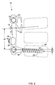
- FIG. 1 An eyebolt assembly of the TSRH ® spinal system sold by Danek Medical Inc. is illustrated in Figure 1 .
- the eyebolt assembly 2 encircles spinal rod 4 such that assembly mass completely surrounds the spinal rod.
- the spinal rod must be inserted through the eyebolt, which rests within the yoke of spinal hook 8.
- the spinal hook attaches the spinal rod to a bony element of the spine.
- a nut 6 is threaded onto a post of the eyeholt assembly to fixably secure the rod within the yoke. The nut is tightened so that the assembly resists axial, torsional, and shear forces to inhibit motion of the spinal rod relative to the assembly in the directions indicated by the arrows in Figure 1 .
- Further details of the TSRH ® spinal system are provided in the TSRH ® Spinal Implant system Surgical Technique Manual and the TSRH ® Crosslink Surgical Technique Manual. Both of these publications are available from Danek Medical Inc.
- some spinal fixation systems include "open back" hooks or screws to allow a spinal rod to be dropped into the open back of the hook or screw and secured within the open back by a separate component and a set screw.
- Such a system is illustrated in U.S. Patent No. 5,102,412 to Rogozinski .
- Such systems tend to be susceptible to fatigue stress failure and require assembly within the surgical wound.
- adding a hook or screw to the construct tends to require that the spinal rod first be repositioned.
- a further disadvantage of this approach is that component mass completely surrounds the spinal rod, resulting in an increase in the profile width of the device and greater impingement of the device upon the fusion mass.
- a low profile width is generally desired to minimize sinus formation and soft tissue irritation from hardware prominence.
- U.S. Patent No. 5,242,445 to Ashman relates to a "split eyebolt" assembly for adding eyebolts to an assembled spinal fixation construction. Attaching the split eyebolt to a spinal rod requires a special crimping tool to crimp the split eyebolt over the rod. The crimping tool tends to be difficult to operate within the Surgical wound. Furthermore, the threads of the opposing sides of the split eyebolt are often misaligned after crimping, making it difficult or impossible to thread a nut onto the split eyebolt. The split eyebolt also completely encircles the spinal rod thereby increasing the impingement of the construct upon the fusion mass.
- an improved spinal fixation system be derived that facilitates assembly and surgical implantation by allowing the spinal rod to be positioned within the surgical wound (a) after the fixation components (e.g., screws, hooks) have been implanted, (b) without modifying the fixation components, and (c) whereby fixation components may be subsequently added, deleted, and/or repositioned without disassembling the system.
- fixation components e.g., screws, hooks
- EP-A-0 578 320 describes a coupler having a yoke and a body that clamp onto a spinal rod. Once the spinal rod is inserted into the yoke and the yoke is placed into the body of the coupler, the position of the spinal rod relative to the coupler is fixed.
- a spinal fixation system as defined in claim 1 that largely eliminates or reduces the aforementioned disadvantages of conventional spinal fixation constructions.
- embodiments of the invention are defined in the dependent claims.
- An advantage of the present invention relates to a fixation component that may be added to or deleted from a spinal fixation construct in a surgical wound without disassembling the construct.
- Another advantage of the present invention relates to a spinal fixation system requiring minimal assembly within the surgical wound.
- Yet another advantage of the present invention relates to a spinal fixation system having a relatively narrow profile width to reduce impingement upon the fusion mass.
- FIG. 2 depicts a spinal fixation system 10 constructed according to teachings of the present invention.
- spinal fixation system 10 includes a spinal rod 12 generally aligned parallel with a portion of the spine, Connector 16 secures spinal fixation components to the spinal rod via fastener 18.
- the fixation components may include various fixation devices including bone screw 14, transverse connector 20, and spinal hooks 22 and 24.
- Spinal rod 12 is preferably constructed of stainless steel or another relatively rigid material.
- the spinal rod preferably has a substantially circular cross-section (although other cross-sectional geometries may be employed) and a diameter between about 0,32 cm (1/8 of an inch) and about 0,64 cm (1/4 of an inch).
- the spinal rod may have a shot-peened surface to increase its resistance to fatigue failure.
- the spinal rod may impart forces against the spine to maintain a portion of the spine in a fixed position to correct a spinal deformity or injury.
- the spinal rod may be contoured to a selected shape prior to or after surgical implantation.
- Bone screw 14 is preferably inserted within the main body of a vertebra 26 and may contain threads 28 to create a fixable engagement with the vertebra.
- the bone screw may have a substantially smooth shank containing no treading.
- the stress imparted to spinal fixation systems resulting from a spinal deformity may cause fatigue failure of a threaded bone screw if a solid spinal fusion does not develop after a period of time.
- Threaded screws having relatively long shanks tend to fail at a location adjacent to the screw head.
- a substantially smooth, unthreaded shank tends to remove the stress concentration on the screw shank from a location adjacent to the screw head where failure of the screw often occurs.
- the bone screw may also include a tap relief 30 to facilitate its insertion into vertebra 26.
- the angle of the bone screw relative to the spinal rod is preferably adjustable.
- the bone screw may be angled to correct the angle 32 of a vertebra relative to other vertebrac in the spine.
- the angle between the bone screw and spinal rod is fixable by tightening fastener 18.
- the height of the vertebra 26 may be adjusted by applying a distraction force in the directions indicated by arrow 34 between a pair of fixation devices such as bone screw 14 and spinal hook 24 prior to tightening fasteners 18.
- the distraction force may be applied with the use of a tool in a manner well known to those skilled in the art.
- the spinal books 22 and 24 may be any of a number of types of hooks well known to those skilled in the art including large laminar, small laminar, thoracic laminar, and pedicle hooks, Each spinal hook may be positioned in the caudal direction (illustrated by hook 24 in Figure 2 ) or in the cranial direction (illustrated by hook 22 in Figure 2 ). Spinal hooks may be positioned on opposing sides of the spinal rod as shown in Figure 2 .
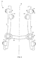
- Figure 3 depicts a top view of an embodiment of spinal fixation system 10 that includes a pair of spinal rods 12 in spaced relation on each side of the vertical axis 40 of the spine.
- Spinal hooks 22 and 24 are positioned for attachment to bony elements of the posterior human spine.
- One or more transverse connectors 20 may be used to rigidly link the rods to improve the strength of the assembly.
- Each of the fixation components may be attached to the spinal rod using a fastener 18 that engages connector 16 and the fixation component.
- Transverse connector 20 may connect neighboring rods to increase the rigidity of the construct and to prevent the movement of the rods relative to one another
- the transverse connector may be attached to the spinal rod using crosslinking plates that are well known to those skilled in the art and described in the TSRH ® crosslink Surgical Technique Manual. It is preferred that neighboring rods be connected by two transverse connectors that may be aligned parallel and in spaced relation from one another. If she spinal rod is bent, transverse connector 20 is preferably attached to the spinal rod at a location other than the "peak" of the curved section of the rod so that additional stress is not placed at that location.
- the convector includes a fastening end 50 and a receiving end 54 opposite the fastening end.
- the fastening end may be a threaded end containing male machine threads 52 that are adapted to engage a fastener.
- the fastener is preferably a nut.
- the receiving end includes a first arm 56 and a second arm 58 that together form a U-shaped borehole 62.
- the first arm has a tip 72 and the second arm has a tip 74 (each labeled in Figure 5 ), and an opening 60 or open end is defined by the tips of the first and second arm.
- a slot 64 extends between the receiving end and the fastening end.
- the slot extends from borehole 62 proximate the' receiving end to a location proximate the fastening end.
- the slot terminates an enlarged opening 66 within the receiving end.
- the borehole is adapted to receive a spinal rod 12 such that the first and second arms of the receiving end surround more than about half of a circumferential portion of the spinal rod.
- the connector does not completely surround the perimeter of the spinal rod.
- the unsurrounded portion of the spinal rod is exposed from the open end 60 of the U-shaped borehole and extends from the borehole through the open end. It is preferred that component mass be placed around only slightly greater than one half of the circumference of the spinal rod to minimize the profile width of the construct. In this manner, the impingement of the construct upon the fusion mass is lessened, thereby reducing irritation of the surrounding tissue and facilitating the development of a correct spinal fusion in a minimal amount of time.
- Conventional assemblies tend to completely surround the spinal rod with component mass, causing a relatively greater impingement upon the fusion mass, which may interfere with fusion development.
- the angle 68 in Figure 4 is defined by the circumferential portion of a spinal rod that is surrounded by the first arm, second arm, and the end of slot 64.
- the angle 68 is preferably less than about 2 ⁇ radians (e,g, 360* around the cross-section of the spinal rod) and greater than about ⁇ radians (e.g., 180* around the cross-section of the spinal rod). More than about half of the circumferential portion the spinal rod is surrounded by a portion of the receiving end (e.g., first arm, second arm, end of slot 64) to allow the spinal rod to be adequately secured within the borehole.
- First arm 58 and second arm 68 engages the surface of greater than about half of the circumferential portion of the spinal rod.
- the first arm and the second arm each have an outside surface that is slightly tapered such that the distance between the outside surfaces of the arms narrows in a direction from tips 72 and 74 to the fastening end 50.
- the taper of the outside surfaces of the arms preferably defines a locking angle 70.
- Locking angle 70 is preferably a conical angle, although it may be formed within a substantially flat wedge instead. Locking angle 70 is preferably less than about 30*, more preferably less than about 25, and more preferably still between about I' and about 20*.
- Figures 5 and 6 illustrate the insertion of spinal rod 12 within borehole 62 in an embodiment of the invention.
- the spinal rod is axially positioned within the borehole by passing the spinal rod through opening 60.
- Slot 64 enables deflection of the first arm and the second arm relative to one another to allow the width of opening 60 to be altered. In the absence of an external forte of a selected magnitude against the first or second arms, the width of opening 60 is less than the outside diameter 76 of the spinal rod.
- Receiving end 54 is adapted to form a "snap-fit" engagement with the spinal rod that may be realized by forcing the spinal rod into the inner surfaces of tips 72 and 74 of the first and second arms, respectively.
- the force against the inner surfaces of the tips 72 and 74 causes the arms to slightly deflect in opposite directions, resulting in a slight widening of at least a portion of the slot.
- the width of opening 60 may increased by an amount sufficient to allow the insertion of the spinal rod through opening 60 and into the borehole.
- connector 16 connects the spinal rod to a fixation component that engages a portion of the spine.
- the fixation component includes a fixation device such as a bone screw, hook, transverse connector, or similar device.
- the fixation component includes a body 80 having a tapered cavity into which connector 16 may be inserted
- the tapered cavity preferably tapers in a direction that is substantially perpendicular to the longitudinal axis of the fixation component.
- the tapered cavity has a first end 84, a second end 86, and an inside surface 82.
- the inside surface 82 is tapered at an angle that corresponds to locking angle 70.
- the tapered cavity narrows in a direction from first end 84 to second end 86.
- the tapered cavity is sized so that fastening end 50 and a portion of receiving end 54 may be inserted within the tapered cavity through an aperture proximate the first end.
- the outer width of the receiving end proximate tips 72 and 74 is slightly greater than the width of the aperture proximate the first end, thereby inhibiting the complete insertion of the receiving end into the tapered cavity.
- Fastener 18 may be a hex and contains female threading 19, which is sized to fit the male machine threads of the fastening end 50.
- the nut engages fastening end 50 and body 80 whereby rotating the fastener in a tightening direction creates a tensile force in the connector in direction 88. Tightening of the fastener moves the connector within the tapered cavity in a direction from first end 84 to second end 86, thereby creating an interference fit between the arms of the receiving end and inside surface 82.
- the arms are deflected toward one another such that the slot is narrowed and the arms of the deceiving end exert a compressive force against the spinal rod disposed within the borehole.
- the magnitude of the compressive force exerted by the receiving end on the spinal rod is variable as a function of the degree to which the fastener is tightened.
- the fastener may be selectively tightened so that the convector is "loosely” engaged to the spinal rod.
- the "loose” engagement fixes the position of the convector on the rod in the absence of a selected force against the connector, while allowing the connector to slide over the surface of the rod upon receiving a distraction force.
- the fastener may be partially tightened to loosely attach a connector and Fixation device onto the rod at a selected location.
- a distraction force may be applied to the connector to move the connector to a selected location on the rod and the fastener may then be fully tightened to maintain the connector at the selected location.
- the arms 56 and 58 exert a clamping force onto "opposite sides" of the rod (i.e.. sections of the outer surface of the spinal rod that are separated by about 180).
- the engagement between the arms 56 and 58 and the "opposite sides” of the spinal rod preferably “centers” the rod within the borehole as shown in Figure 6 so that substantially no gaps exist between the inner surface af the arms and the spinal rod.
- the rod may be constrained on opposing sides in this manner to provide further resistance to forces that might otherwise result in axial movement of the rod.
- a “locking taper” engagement is taken to mean a largely irreversible deflection of the receiving end. That is, if the fastener becomes loose after the receiving end has been compressed about the spinal rod, the clamping force exerted by the receiving end will be maintained to fixably hold the spinal rod within the borehole.
- a transverse connector 20 is disposed between a pair of spinal tods in spaced relation to secure the rods at a fixed distance 90.
- the spins rods are fixed within the borehole of a connector in the manner depicted in Figures 5 and 6 and described above.
- the transverse connector may include a bevelled surface between body 80 and a reduced section 92. Reduced section 92 preferably has a smaller width or diameter than body 80 to allow the reduced section to be bent more easily. Slight variations in distance 39 may be achieved by bending transverse connector 20 proximate reduced section 92.
- the bending of the transverse connector may be accomplished using a rod bender and a method well known to those skilled in the art.
- the transverse connector may have a substantially constant width or diameter such that the width of section 92 and the width of body 80 are approximately equal.
- the fixation component may include a bout screw that is used to correct the angle 32 between vertebrae. It is preferred that the bone screw be adapted to pivot about the spinal rod to form an oblique angle between the longitudinal axis of the spinal rod and the shank of the bone screw.
- the bone screw can be pivoted in either direction 96 or direction 98 such that an oblique angle between about 90° and about 60° is formed between the shank and the longitudinal axis of the spinal rod.
- Other Fixation devices e.g., hooks
- the tapered cavity may contain an engaging side 100 adapted to contact flat 102 of connector 16 to limit the pivoting of a fixation device (e.g., bone screw) about the spinal rod within a selected range, thereby preventing a gross misalignment that might complicate the assembly of the construct during a surgical procedure.
- a fixation device e.g., bone screw
- Body 80 includes a top section 104 and a bottom section 106 that together form a U-shaped yoke 112 that is substantially perpendicular to inside surface 82 of the tapered cavity.
- the fixation component may pivot about the spinal rod.
- the edges of top section 104 and/or bottom section 106 may contact the spinal rod to prevent the pivoting of the fixation component about the spinal rod beyond a selected degree.
- Top section 104 contains a curved edge 108
- bottom section 106 contains a curved edge 110
- Curved edges 108 and 110 increase the degree that the fixation component can pivot and allow a fixation device (e.g., bone screw 14) to form an angle within a selected range that is perpendicular with or oblique to the spinal rod.
- a fixation device e.g., bone screw 14
- body 80 is laterally offset from the spinal rod.
- Body 80 may contain a spacer 114 that extends laterally to offset a fixation component from the spinal rod. Offsetting a fixation component from the spinal rod may reduce the degree that the spinal rod must be contoured for proper positioning of bone screws (e.g., pedicle screws) in regions of the spine such as the lower lumbar region.
- the offset between the fixation component and the spinal rod may be equal to the width of the spacer.
- the offset is preferably less than about 15 mm, more preferably less than about 10 mm, and more preferably still between about 3 mm and about 9 mm.
- the spacer may contain a tapered cavity for receiving connector 16 as illustrated in Figure 9 .
- the spacer contains a first plurality af protrusions or teeth that are adapted to format an engagement with a second plurality of protrusions or teeth 120 disposed on a surface of a fixation device.
- the teeth of the spacer and the teeth of the fixation device preferably are radially spaced at a fixed spacing 118.
- the teeth of the spacer and the protrusions of the fixation device preferably form a complementary fit such that adjacent, opposing teeth contact one another over interface length 116 when fastener 18 is tightened.
- the complementary engagement of the teeth preferably inhibits and/or prevents the fixation device from rotating about spacer 114, thereby fixing the angle formed between the Station device and the spinal rod.
- the body 80 of the hook preferably includes a first U-shaped yoke 137 disposed on a first side 134 of the body and a second U-shaped yoke 138 disposed on a second side 136 of the body.
- a cavity 132 preferably extends through the body from the first side 134 to the second side 136.
- the cavity preferably contains a pair of tapered inner surfaces 133 and 135 that taper in opposite directions such that the cavity narrows in a direction from the first side 134 to the middle of the cavity and narrows in a direction from the second side 136 to the middle of the cavity.
- the tapered inner surfaces each terminate in an engaging portion 130 disposed in the middle of the cavity.
- Connector 16 may be positioned within the cavity so that the receiving end extends from either first side 134 as shown in Figure 10B or from second side 136 as shown in Figure 10C .
- the reversible hook may be mounted so that either first side 134 or second side 136 is proximate the spinal rod, with the hook directed toward either the caudal or cranial direction in each case.
- the fixation component contains a slot 109 through which the fastening end of the connector may be inserted during assembly of the construct.
- the engaging portion 130 engages the outer surface of the receiving end to limit the extent to which the receiving end may be inserted into cavity 132.
- Fastener 18 engages body 80 proximate the engaging portion.
- FIG. 11 An alternate embodiment including a spacer 114 is illustrated in Figure 11 .
- the spacer surrounds a portion of connector 16 and contains a tapered surface 140 corresponding to the outside surface of the arms of the receiving end.
- the connector is drawn within the spacer whereby surface 140 engages and exerts a clamping force against the outer surface of the receiving end.
- a tensile forces created by the tightening of fastener 18 maintains the spacer in a fixed position between body 80 and the spinal rod.
- the tapered surface 140 terminates in an engaging surface 142 that engages the receiving end, thereby limiting the extent to which the receiving end may be drawn within the spacer.
- the receiving end forms a "pinch clamp" about the spinal rod, wherein the tips 72 and 74 of the arms terminate slightly beyond a vertical axis 144, which extends through the center of the spinal rod.
- the fastener may be fully tightened to create a selected offset length 145 that is preferably between about 2 num and about 10 mm.
- the threaded end of connector 16 is inserted through the tapered cavity of a spinal fixation component and fastener 18 is loosely threaded onto the threaded end.
- the spinal fixation component is then attached to the spine via a hook or screw in a selected location.
- a plurality of spiral fixation components are attached to the spine in like manner.
- Spinal rod 11 may be contoured to match the desired curvature of the spine and placed into the surgical opening. The spinal rod is snapped within the borehole of the connector of each spinal fixation component.
- each of the vertebra is at a selected angle and height relative to neighboring vertebrae and then each fastener 18 is fully tightened to fixably secure the spinal rod into the borehole of each connector and to secure each of the spinal fixation devices at a selected angle relative to the spinal rod.
- the only assembly of system components that occurs within the surgical wound is (a) the snapping of the spinal rod within one or more connectors and (b) the final tightening of one or more fasteners that have already been engaged with the fastening end.
- Each of the fasteners is tightened with a torque of at least 16,9 N-m (150 lb-in).
- One or more transverse connectors may be added across neighboring spinal rods for support to increase the strength of the overall construct and maintain the spinal rods at a fixed distance from one another.
- each connector and spinal fixation component can be pre-assembled on the spinal rod prior to the implantation of the rod into the surgical wound.
- a connector may first be snapped onto the spinal rod.
- a fixation component may be added onto the connector such that the fastening end of the connector extends through the tapered cavity and the arms of the receiving end contact the inner surface of the tapered cavity.
- the fastener is positioned on the fastening end and partially tightened to maintain the connector and fixation component engaged with the spinal rod.
- the fastener is loosely secured on the fastening end to allow the connector and fixation component to slide along the length of the rod when a selected force is applied to the connector.
- the spinal rod may be contoured as necessary, and the pre-assembled system may be inserted within the surgical wound.
- the location of the spinal fixation components may be adjusted along the length of the rod as necessary, and the construct may be connected to the spine via fixation devices. Once a fixation component is placed at a selected location, its corresponding fastener may be fully tightened to fix its location. Fixation components may be added to or deleted from the construct as necessary without altering the position of the spinal rod or other fixation components.
- the system may be partially pre-assembled such that a number of connectors are initially snapped onto the spinal rod.
- Fixation components may be inserted within the surgical wound and connected to the spine at selected locations via fixation devices.
- the rod may be selectively contoured and inserted within the surgical wound and aligned proximate the spine.
- a connector is slid along the rod to a selected location proximate a fixation component on the spine, and the fastening end of the connector is inserted through the tapered cavity of the Fixation component.
- a fastener may be placed on the fastening end to clamp the connector onto the spinal rod and to secure the fixation components therebetween. Additional connectors and fixation components may be secured to the spinal rod in like manner.
- fixation components may have to be removed from the construct to slide the added fixation component to a selected position.
- Connector 16 is snapped onto the spinal rod at a selected location.
- a connector and away Fixation device e.g., screw, hook transverse connector may be added to the spinal rod without remaking fixation components from the spinal rod or removing the spinal rod from the surgical wound.
- a connector and fixation device may be removed from the spinal rod without altering the position of the spinal rod or adjacent connectors.
- the fastener 18 may be loosened and a tool may be used to unclamp the receiving end of the connector from the spinal rod, thereby eliminating the need to slide the component off the end of the spinal rod as in some conventional systems.
Description
- The present invention generally relates to spinal fixation systems and the like. More particularly, an embodiment of the invention relates to a spinal implant system for correction, fixation, and stabilisation of the human spine to allow the development of a solid spinal fusion.
- Spinal Fixation, such as lumbar sacral fusion and the correction of spinal deformities such as scoliotic curves, is a well known and frequently used medical procedure. Pedicle, lateral, and oblique mounting devices may be used to secure corrective spinal instrumentation to a portion of the spine that has been selected to be fused by arthrodesis.
- A spinal fixation system typically includes corrective spinal instrumentation that is attached to selected vertebrae of the spine by screws, hooks, and clamps. The corrective spinal instrumentation includes spinal rods or plates that are generally parallel to the patient's back. The corrective spinal instrumentation may also include transverse connecting rods that extend between neighboring spinal rods. Spinal fixation systems are used to correct problems in the lumbar and thoracic portions of the spine, and are often installed posterior to the spine on opposite sides of the spinous process and adjacent to the transverse process.
- Various types of screws, hooks, and clamps have been used for attaching corrective spinal instrumentation to selected portions of the patient's spine. Examples of pedicle screws and other types of attachments are illustrated in
U.S. Patent Nos. 4,763,644 ;4,805,602 ;4,887,596 ;4,950,269 ; and5,129,388 . - An eyebolt assembly of the TSRH® spinal system sold by Danek Medical Inc. is illustrated in
Figure 1 . Theeyebolt assembly 2 encirclesspinal rod 4 such that assembly mass completely surrounds the spinal rod. The spinal rod must be inserted through the eyebolt, which rests within the yoke ofspinal hook 8. The spinal hook attaches the spinal rod to a bony element of the spine. Anut 6 is threaded onto a post of the eyeholt assembly to fixably secure the rod within the yoke. The nut is tightened so that the assembly resists axial, torsional, and shear forces to inhibit motion of the spinal rod relative to the assembly in the directions indicated by the arrows inFigure 1 . Further details of the TSRH® spinal system are provided in the TSRH® Spinal Implant system Surgical Technique Manual and the TSRH® Crosslink Surgical Technique Manual. Both of these publications are available from Danek Medical Inc. - Manual insertion of a spinal rod through the bores of a number of spaced-apart eyebolts within a surgical wound tends to be difficult. The bore axis of each eyebolt must be properly aligned along a common axis, which is difficult since the corrective procedure requires that the spinal rod initially be placed under stress to resist deforming forces of the spine. Therefore, the use of system such as the TSRH® spinal system may require that a predetermined lumber of screws or hooks be pre-loaded onto the spinal rod in a particular order and spacing prior to the insertion of the spinal rod into the surgical wound. After insertion of the spinal system into the surgical wound, however, it is often necessary to add, delete, or reposition one or moro hooks or screws. Before such modifications can be made, the spinal system typically must be removed from the surgical wound and at least partially disassembled.
- To overcome such problems, some spinal fixation systems include "open back" hooks or screws to allow a spinal rod to be dropped into the open back of the hook or screw and secured within the open back by a separate component and a set screw. Such a system is illustrated in
U.S. Patent No. 5,102,412 to Rogozinski . Such systems tend to be susceptible to fatigue stress failure and require assembly within the surgical wound. In addition, adding a hook or screw to the construct tends to require that the spinal rod first be repositioned. A further disadvantage of this approach is that component mass completely surrounds the spinal rod, resulting in an increase in the profile width of the device and greater impingement of the device upon the fusion mass. A low profile width is generally desired to minimize sinus formation and soft tissue irritation from hardware prominence. -
U.S. Patent No. 5,242,445 to Ashman relates to a "split eyebolt" assembly for adding eyebolts to an assembled spinal fixation construction. Attaching the split eyebolt to a spinal rod requires a special crimping tool to crimp the split eyebolt over the rod. The crimping tool tends to be difficult to operate within the Surgical wound. Furthermore, the threads of the opposing sides of the split eyebolt are often misaligned after crimping, making it difficult or impossible to thread a nut onto the split eyebolt. The split eyebolt also completely encircles the spinal rod thereby increasing the impingement of the construct upon the fusion mass. - It is therefore desirable that an improved spinal fixation system be derived that facilitates assembly and surgical implantation by allowing the spinal rod to be positioned within the surgical wound (a) after the fixation components (e.g., screws, hooks) have been implanted, (b) without modifying the fixation components, and (c) whereby fixation components may be subsequently added, deleted, and/or repositioned without disassembling the system.
-
EP-A-0 578 320 describes a coupler having a yoke and a body that clamp onto a spinal rod. Once the spinal rod is inserted into the yoke and the yoke is placed into the body of the coupler, the position of the spinal rod relative to the coupler is fixed. - In accordance to the present invention a spinal fixation system as defined in
claim 1 is provided that largely eliminates or reduces the aforementioned disadvantages of conventional spinal fixation constructions. embodiments of the invention are defined in the dependent claims. - An advantage of the present invention relates to a fixation component that may be added to or deleted from a spinal fixation construct in a surgical wound without disassembling the construct.
- Another advantage of the present invention relates to a spinal fixation system requiring minimal assembly within the surgical wound.
- Yet another advantage of the present invention relates to a spinal fixation system having a relatively narrow profile width to reduce impingement upon the fusion mass.
- Further advantages of the present invention will become apparent to those skilled in the art with the benefit of the following detailed description of the preferred embodiments and upon reference to the accompanying drawings in which:
-
Figure 1 depicts a TSRH® spinal system eyebolt assembly; -
Figure 2 depicts a side view of an embodiment of a spinal fixation system connected to a vertebra; -
Figure 3 depicts a top view of the spinal fixation system ofFigure 1 ; -
Figure 4 depicts a side view of a tapered connector constructed in accordance with the present invention; -
Figure 5 depicts a side view of a tapered connector prior to assembly with a fixation component body and a spinal rod; -
Figure 6 depicts a side view of a tapered connector assembled with a spinal fixation component and a spinal rod; -
Figure 7 depicts a side view of a transverse connector disposed between a pair of spinal rods in accordance with the present invention; -
Figure 8 depicts a front view and side view partially in section of a bone screw constructed according to teachings of the present invention; -
Figure 9 depicts a front view and side view partially in section of a bone screw having radially-spaced protrusions in accordance with the present invention; -
Figure 10 depicts a front view and a side view partially in section of a reversible fixation component constructed according to teachings or the present invention; -
Figure 11 depicts a side view partially in section of a spacer disposed between a spinal rod and a fastener in accordance with the present invention; - While the invention is susceptible to various modifications and alternative forms, specific embodiments thereof are shown by way of example in the drawings and will herein be described in detail. It should be understood, however, that the drawings and detailed description thereto are not intended to limit the invention to the particular form disclosed, but on the contrary, the intention is to cover all modifications, equivalents and alternatives falling within the scope of the present invention as defined by the appended claims.
-
Figure 2 depicts aspinal fixation system 10 constructed according to teachings of the present invention. In an embodiment of the invention,spinal fixation system 10 includes aspinal rod 12 generally aligned parallel with a portion of the spine,Connector 16 secures spinal fixation components to the spinal rod viafastener 18. The fixation components may include various fixation devices includingbone screw 14,transverse connector 20, andspinal hooks -
Spinal rod 12 is preferably constructed of stainless steel or another relatively rigid material. The spinal rod preferably has a substantially circular cross-section (although other cross-sectional geometries may be employed) and a diameter between about 0,32 cm (1/8 of an inch) and about 0,64 cm (1/4 of an inch). The spinal rod may have a shot-peened surface to increase its resistance to fatigue failure. The spinal rod may impart forces against the spine to maintain a portion of the spine in a fixed position to correct a spinal deformity or injury. The spinal rod may be contoured to a selected shape prior to or after surgical implantation. -
Bone screw 14 is preferably inserted within the main body of avertebra 26 and may containthreads 28 to create a fixable engagement with the vertebra. Alternatively, the bone screw may have a substantially smooth shank containing no treading. The stress imparted to spinal fixation systems resulting from a spinal deformity may cause fatigue failure of a threaded bone screw if a solid spinal fusion does not develop after a period of time. Threaded screws having relatively long shanks tend to fail at a location adjacent to the screw head. A substantially smooth, unthreaded shank tends to remove the stress concentration on the screw shank from a location adjacent to the screw head where failure of the screw often occurs. The bone screw may also include atap relief 30 to facilitate its insertion intovertebra 26. The angle of the bone screw relative to the spinal rod is preferably adjustable. The bone screw may be angled to correct theangle 32 of a vertebra relative to other vertebrac in the spine. The angle between the bone screw and spinal rod is fixable by tighteningfastener 18. Furthermore, the height of thevertebra 26 may be adjusted by applying a distraction force in the directions indicated byarrow 34 between a pair of fixation devices such asbone screw 14 andspinal hook 24 prior to tighteningfasteners 18. The distraction force may be applied with the use of a tool in a manner well known to those skilled in the art. - The
spinal books hook 24 inFigure 2 ) or in the cranial direction (illustrated byhook 22 inFigure 2 ). Spinal hooks may be positioned on opposing sides of the spinal rod as shown inFigure 2 . -
Figure 3 depicts a top view of an embodiment ofspinal fixation system 10 that includes a pair ofspinal rods 12 in spaced relation on each side of thevertical axis 40 of the spine. Spinal hooks 22 and 24 are positioned for attachment to bony elements of the posterior human spine. One or moretransverse connectors 20 may be used to rigidly link the rods to improve the strength of the assembly. Each of the fixation components may be attached to the spinal rod using afastener 18 that engagesconnector 16 and the fixation component. -
Transverse connector 20 may connect neighboring rods to increase the rigidity of the construct and to prevent the movement of the rods relative to one another, The transverse connector may be attached to the spinal rod using crosslinking plates that are well known to those skilled in the art and described in the TSRH® crosslink Surgical Technique Manual. It is preferred that neighboring rods be connected by two transverse connectors that may be aligned parallel and in spaced relation from one another. If she spinal rod is bent,transverse connector 20 is preferably attached to the spinal rod at a location other than the "peak" of the curved section of the rod so that additional stress is not placed at that location. - An embodiment of
connector 16 is illustrated inFigure 4 . The convector includes afastening end 50 and a receivingend 54 opposite the fastening end. The fastening end may be a threaded end containingmale machine threads 52 that are adapted to engage a fastener. The fastener is preferably a nut. The receiving end includes afirst arm 56 and asecond arm 58 that together form a U-shaped borehole 62. The first arm has atip 72 and the second arm has a tip 74 (each labeled inFigure 5 ), and anopening 60 or open end is defined by the tips of the first and second arm. Aslot 64 extends between the receiving end and the fastening end. The slot extends from borehole 62 proximate the' receiving end to a location proximate the fastening end. The slot terminates anenlarged opening 66 within the receiving end. The borehole is adapted to receive aspinal rod 12 such that the first and second arms of the receiving end surround more than about half of a circumferential portion of the spinal rod. - The connector does not completely surround the perimeter of the spinal rod. The unsurrounded portion of the spinal rod is exposed from the
open end 60 of the U-shaped borehole and extends from the borehole through the open end. It is preferred that component mass be placed around only slightly greater than one half of the circumference of the spinal rod to minimize the profile width of the construct. In this manner, the impingement of the construct upon the fusion mass is lessened, thereby reducing irritation of the surrounding tissue and facilitating the development of a correct spinal fusion in a minimal amount of time. Conventional assemblies tend to completely surround the spinal rod with component mass, causing a relatively greater impingement upon the fusion mass, which may interfere with fusion development. - The
angle 68 inFigure 4 is defined by the circumferential portion of a spinal rod that is surrounded by the first arm, second arm, and the end ofslot 64. Theangle 68 is preferably less than about 2π radians (e,g, 360* around the cross-section of the spinal rod) and greater than about π radians (e.g., 180* around the cross-section of the spinal rod). More than about half of the circumferential portion the spinal rod is surrounded by a portion of the receiving end (e.g., first arm, second arm, end of slot 64) to allow the spinal rod to be adequately secured within the borehole. If less than half of the circumferential portion of the spinal rod were surrounded by the receiving end, forces resulting from spinal deformations might tend to pull the spinal rod from within borehole 62.First arm 58 andsecond arm 68 engages the surface of greater than about half of the circumferential portion of the spinal rod. - The first arm and the second arm each have an outside surface that is slightly tapered such that the distance between the outside surfaces of the arms narrows in a direction from
tips fastening end 50. The taper of the outside surfaces of the arms preferably defines a lockingangle 70. Lockingangle 70 is preferably a conical angle, although it may be formed within a substantially flat wedge instead. Lockingangle 70 is preferably less than about 30*, more preferably less than about 25, and more preferably still between about I' and about 20*. -
Figures 5 and 6 illustrate the insertion ofspinal rod 12 within borehole 62 in an embodiment of the invention. The spinal rod is axially positioned within the borehole by passing the spinal rod throughopening 60.Slot 64 enables deflection of the first arm and the second arm relative to one another to allow the width of opening 60 to be altered. In the absence of an external forte of a selected magnitude against the first or second arms, the width of opening 60 is less than theoutside diameter 76 of the spinal rod. Receivingend 54 is adapted to form a "snap-fit" engagement with the spinal rod that may be realized by forcing the spinal rod into the inner surfaces oftips tips opening 60 and into the borehole. Once the spinal rod is fully inserted within the borehole (as shown inFigure 6 ), the arms move back toward one another, causing the slot to narrow to its initial, unstressed width If the diameter of the spinal rod is slightly greater than that of the borehole, the arms may remain slightly deflected and the slot may remain slightly widened after the spinal rod is snapped into the borehole. It is generally preferred that the diameter of the spinal rod and the diameter of the borehole be equal. - In an embodiment of the invention,
connector 16 connects the spinal rod to a fixation component that engages a portion of the spine. The fixation component includes a fixation device such as a bone screw, hook, transverse connector, or similar device. The fixation component includes abody 80 having a tapered cavity into whichconnector 16 may be inserted The tapered cavity preferably tapers in a direction that is substantially perpendicular to the longitudinal axis of the fixation component. The tapered cavity has afirst end 84, asecond end 86, and aninside surface 82. Theinside surface 82 is tapered at an angle that corresponds to lockingangle 70. The tapered cavity narrows in a direction fromfirst end 84 tosecond end 86. The tapered cavity is sized so that fasteningend 50 and a portion of receivingend 54 may be inserted within the tapered cavity through an aperture proximate the first end. The outer width of the receiving endproximate tips -
Fastener 18 may be a hex and containsfemale threading 19, which is sized to fit the male machine threads of thefastening end 50. The nut engages fasteningend 50 andbody 80 whereby rotating the fastener in a tightening direction creates a tensile force in the connector indirection 88. Tightening of the fastener moves the connector within the tapered cavity in a direction fromfirst end 84 tosecond end 86, thereby creating an interference fit between the arms of the receiving end and insidesurface 82. As the fastener is tightened, the arms are deflected toward one another such that the slot is narrowed and the arms of the deceiving end exert a compressive force against the spinal rod disposed within the borehole. - The magnitude of the compressive force exerted by the receiving end on the spinal rod is variable as a function of the degree to which the fastener is tightened. The fastener may be selectively tightened so that the convector is "loosely" engaged to the spinal rod. The "loose" engagement fixes the position of the convector on the rod in the absence of a selected force against the connector, while allowing the connector to slide over the surface of the rod upon receiving a distraction force. For instance, the fastener may be partially tightened to loosely attach a connector and Fixation device onto the rod at a selected location. A distraction force may be applied to the connector to move the connector to a selected location on the rod and the fastener may then be fully tightened to maintain the connector at the selected location.
- The
arms arms Figure 6 so that substantially no gaps exist between the inner surface af the arms and the spinal rod. The rod may be constrained on opposing sides in this manner to provide further resistance to forces that might otherwise result in axial movement of the rod. When thearms - In an embodiment of the invention depicted in
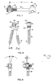
Figure 7 , atransverse connector 20 is disposed between a pair of spinal tods in spaced relation to secure the rods at a fixeddistance 90. The spins rods are fixed within the borehole of a connector in the manner depicted inFigures 5 and 6 and described above. The transverse connector may include a bevelled surface betweenbody 80 and a reducedsection 92.Reduced section 92 preferably has a smaller width or diameter thanbody 80 to allow the reduced section to be bent more easily. Slight variations in distance 39 may be achieved by bendingtransverse connector 20 proximate reducedsection 92. The bending of the transverse connector may be accomplished using a rod bender and a method well known to those skilled in the art. Alternately, the transverse connector may have a substantially constant width or diameter such that the width ofsection 92 and the width ofbody 80 are approximately equal. - The fixation component may include a bout screw that is used to correct the
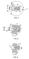
angle 32 between vertebrae. It is preferred that the bone screw be adapted to pivot about the spinal rod to form an oblique angle between the longitudinal axis of the spinal rod and the shank of the bone screw. The bone screw can be pivoted in eitherdirection 96 ordirection 98 such that an oblique angle between about 90° and about 60° is formed between the shank and the longitudinal axis of the spinal rod. Other Fixation devices (e.g., hooks) may be pivoted with respect the spinal rod in the same manner. As illustrated inFigure 8 , the tapered cavity may contain anengaging side 100 adapted to contact flat 102 ofconnector 16 to limit the pivoting of a fixation device (e.g., bone screw) about the spinal rod within a selected range, thereby preventing a gross misalignment that might complicate the assembly of the construct during a surgical procedure. -
Body 80 includes atop section 104 and abottom section 106 that together form aU-shaped yoke 112 that is substantially perpendicular toinside surface 82 of the tapered cavity. The fixation component may pivot about the spinal rod. The edges oftop section 104 and/orbottom section 106 may contact the spinal rod to prevent the pivoting of the fixation component about the spinal rod beyond a selected degree.Top section 104 contains acurved edge 108, andbottom section 106 contains acurved edge 110,Curved edges - In an embodiment of the invention,
body 80 is laterally offset from the spinal rod.Body 80 may contain aspacer 114 that extends laterally to offset a fixation component from the spinal rod. Offsetting a fixation component from the spinal rod may reduce the degree that the spinal rod must be contoured for proper positioning of bone screws (e.g., pedicle screws) in regions of the spine such as the lower lumbar region. The offset between the fixation component and the spinal rod may be equal to the width of the spacer. The offset is preferably less than about 15 mm, more preferably less than about 10 mm, and more preferably still between about 3 mm and about 9 mm. - The spacer may contain a tapered cavity for receiving
connector 16 as illustrated inFigure 9 . In an embodiment, the spacer contains a first plurality af protrusions or teeth that are adapted to format an engagement with a second plurality of protrusions orteeth 120 disposed on a surface of a fixation device. The teeth of the spacer and the teeth of the fixation device preferably are radially spaced at a fixedspacing 118. The teeth of the spacer and the protrusions of the fixation device preferably form a complementary fit such that adjacent, opposing teeth contact one another overinterface length 116 whenfastener 18 is tightened. The complementary engagement of the teeth preferably inhibits and/or prevents the fixation device from rotating aboutspacer 114, thereby fixing the angle formed between the Station device and the spinal rod. - An embodiment including a reversible fixation device is illustrated in
Figure 10 . Thebody 80 of the hook preferably includes a firstU-shaped yoke 137 disposed on afirst side 134 of the body and a secondU-shaped yoke 138 disposed on asecond side 136 of the body. Acavity 132 preferably extends through the body from thefirst side 134 to thesecond side 136. The cavity preferably contains a pair of taperedinner surfaces first side 134 to the middle of the cavity and narrows in a direction from thesecond side 136 to the middle of the cavity. The tapered inner surfaces each terminate in an engagingportion 130 disposed in the middle of the cavity.Connector 16 may be positioned within the cavity so that the receiving end extends from eitherfirst side 134 as shown inFigure 10B or fromsecond side 136 as shown inFigure 10C . Thus, the reversible hook may be mounted so that eitherfirst side 134 orsecond side 136 is proximate the spinal rod, with the hook directed toward either the caudal or cranial direction in each case. The fixation component contains aslot 109 through which the fastening end of the connector may be inserted during assembly of the construct. The engagingportion 130 engages the outer surface of the receving end to limit the extent to which the receiving end may be inserted intocavity 132.Fastener 18 engagesbody 80 proximate the engaging portion. - An alternate embodiment including a
spacer 114 is illustrated inFigure 11 . The spacer surrounds a portion ofconnector 16 and contains atapered surface 140 corresponding to the outside surface of the arms of the receiving end. Asfastener 18 is tightened, the connector is drawn within the spacer wherebysurface 140 engages and exerts a clamping force against the outer surface of the receiving end. A tensile forces created by the tightening offastener 18 maintains the spacer in a fixed position betweenbody 80 and the spinal rod. Thetapered surface 140 terminates in anengaging surface 142 that engages the receiving end, thereby limiting the extent to which the receiving end may be drawn within the spacer. The receiving end forms a "pinch clamp" about the spinal rod, wherein thetips vertical axis 144, which extends through the center of the spinal rod. The fastener may be fully tightened to create a selected offsetlength 145 that is preferably between about 2 num and about 10 mm. - To surgically install
spinal fixation system 10, the threaded end ofconnector 16 is inserted through the tapered cavity of a spinal fixation component andfastener 18 is loosely threaded onto the threaded end. The spinal fixation component is then attached to the spine via a hook or screw in a selected location. A plurality of spital fixation components are attached to the spine in like manner. Spinal rod 11 may be contoured to match the desired curvature of the spine and placed into the surgical opening. The spinal rod is snapped within the borehole of the connector of each spinal fixation component. The spine is manipulated such that each of the vertebra is at a selected angle and height relative to neighboring vertebrae and then eachfastener 18 is fully tightened to fixably secure the spinal rod into the borehole of each connector and to secure each of the spinal fixation devices at a selected angle relative to the spinal rod. It is generally preferred that the only assembly of system components that occurs within the surgical wound is (a) the snapping of the spinal rod within one or more connectors and (b) the final tightening of one or more fasteners that have already been engaged with the fastening end. Each of the fasteners is tightened with a torque of at least 16,9 N-m (150 lb-in). One or more transverse connectors may be added across neighboring spinal rods for support to increase the strength of the overall construct and maintain the spinal rods at a fixed distance from one another. - In an alternate embodiment, each connector and spinal fixation component can be pre-assembled on the spinal rod prior to the implantation of the rod into the surgical wound. A connector may first be snapped onto the spinal rod. A fixation component may be added onto the connector such that the fastening end of the connector extends through the tapered cavity and the arms of the receiving end contact the inner surface of the tapered cavity. The fastener is positioned on the fastening end and partially tightened to maintain the connector and fixation component engaged with the spinal rod. The fastener is loosely secured on the fastening end to allow the connector and fixation component to slide along the length of the rod when a selected force is applied to the connector. The spinal rod may be contoured as necessary, and the pre-assembled system may be inserted within the surgical wound. The location of the spinal fixation components may be adjusted along the length of the rod as necessary, and the construct may be connected to the spine via fixation devices. Once a fixation component is placed at a selected location, its corresponding fastener may be fully tightened to fix its location. Fixation components may be added to or deleted from the construct as necessary without altering the position of the spinal rod or other fixation components.
- In an alternate embodiment, the system may be partially pre-assembled such that a number of connectors are initially snapped onto the spinal rod. Fixation components may be inserted within the surgical wound and connected to the spine at selected locations via fixation devices. The rod may be selectively contoured and inserted within the surgical wound and aligned proximate the spine. A connector is slid along the rod to a selected location proximate a fixation component on the spine, and the fastening end of the connector is inserted through the tapered cavity of the Fixation component. A fastener may be placed on the fastening end to clamp the connector onto the spinal rod and to secure the fixation components therebetween. Additional connectors and fixation components may be secured to the spinal rod in like manner.
- After the rod is implanted into the surgical wound it may be necessary to add or delete a fixation components. Conventional systems tend to require that the spinal rod be removed from the surgical wound to allow a fixation component to be threaded onto or removed from the rod. In addition, fixation components of conventional systems may have to be removed from the construct to slide the added fixation component to a selected position.
Connector 16 is snapped onto the spinal rod at a selected location. Thus, a connector and away Fixation device (e.g., screw, hook transverse connector may be added to the spinal rod without remaking fixation components from the spinal rod or removing the spinal rod from the surgical wound. In the same manner, a connector and fixation device may be removed from the spinal rod without altering the position of the spinal rod or adjacent connectors. Thefastener 18 may be loosened and a tool may be used to unclamp the receiving end of the connector from the spinal rod, thereby eliminating the need to slide the component off the end of the spinal rod as in some conventional systems. - Further modifications and alternative embodiments of various aspects of the invention will be apparent to those skilled in the art in view of this description. Accordingly, this description is to be construed as indicative only and is for the purpose of teaching those skilled in the art the general manner of carrying out the invention It is to be understood that the forms of the invention shown and described herein are to be taken as the presently preferred embodiments. Elements and materials may be substituted for those illustrated and described herein, parts and processes may be reversed, and certain features of the invention may be utilized independently, all as would be apparent to one skilled in the art after having the benefit of this description of the invention. Changes may be made in the elements described herein without departing from the scope of the invention as described in the following claims.
Claims (21)
- A spinal fixation system (10) for fixation of the human spine, comprising :- a connector (16) comprising a receiving end (54), wherein the receiving end (54) forms a substantially U-shaped borehole (62) having an opening (60);- a spinal rod (12) axially positionable within the borehole (62) during use;- a fixation component comprising a fixation device (14, 22, 24) for attaching the spinal rod to a vertebra and a body (80), the body (80) comprising a cavity (82, 132) configured to receive the receiving end (54) of the connector (16),characterized in that:the connector (16) comprises a fastening end (50) and a receiving end, and the spinal fixation system further comprises a fastener (18) configured to engage the fastening end (50) of the connector (16), whereby tightening of the fastener (18) draws at least a portion of the receiving end (54) through the cavity (82, 132), causing the inner surface of the cavity (82, 132) to compress the receiving end (54) of the connector (16) to secure the spinal rod (12) within the borehole (62) during use.
- The spinal fixation system (10) of claim 1, wherein the cavity is tapered in a direction that is substantially perpendicular to a longitidinal axis of the fixation component.
- The spinal fixation system (10) of claim 1, wherein the connector (16) comprises a slot (64) extending from the U-shaped borehole (62) into at least a portion of the fastening end (50) of the connector (16).
- The spinal fixation system (10) of claim 1, wherein the fastening end of the connector (16) comprises a threaded surface.
- The spinal fixation system (10) of claim 1 wherein the fastening end (50) of the connector (16) is threaded and the receiving end (54) of the connector (16) terminates in a first arm (56) and a second arm (58) that together form the substantially U-shaped borehole (62), the first arm (56) comprising a first tip (72) and the second arm (58) comprising a second tip (74), and wherein an open end (60) is formed between the first tip (72) and the second tip (74).
- The spinal fixation system (10) of claim 5, wherein the fastener (18) is a nut adapted to engage the fastening end (50) of the connector (16) and the body (80) of the fixation component, and wherein the nut is adapted to being tightened to cause movement of the receiving end (54) within the tapered cavity and movement of the first and second arms (56,59) such that the first and second arms (56,58) exert a compressive force against the spinal rod (12).
- The spinal fixation system (10) of claim 5, wherein the width of the opening (60) of the borehole (62) is defined by the first tip (72) of the first arm (56) and the second tip (74) of the second arm (58).
- The spinal fixation system (10) of claim 5, further comprising a slot (64) extending between the fastening end (50) and the receiving end (54) of the connector (16).
- The spinal fixation system (10) of claim 8, wherein the first and second arms (56,58) are movable to cause a narrowing or widening of a portion of the slot (64) and variation of the width of the opening (60) to allow the spinal rod (12) to be snapped into the borehole (62) through the opening (60) to form a fixable engagement between the spinal rod (12) and the receiving end (54) of the connector (16).
- The spinal fixation system (10) of claim 1, wherein the fixation component further comprise a bone screw (14).
- The spinal fixation system (10) of claim 1, wherein the fixation component further comprises a hook (22) for engaging a bone.
- The spinal fixation system (10) of claim 1. wherein the fixation component body (80) comprises a substantially U-shaped yoke (112) having an axial length, the yoke (112) being formed between a top section (104) and a bottom section (106), the top section (104) comprising a first edge (108), the bottom section (106) comprising a second edge (110), the first and second edges (108,110) defining a width of the yoke (112), and wherein the first and second edges (108.110) are curved such that the width of the yoke (112) varies across the axial length of the yoke (112).
- The spinal fixation system (10) of claim 1, wherein the Fixation component further comprises a spacer (114) adapted to fit between the connector (16) and the fixation component to laterally offset the fixation device from the spinal rod (12).
- The spinal fixation system (10) of claim 1, wherein the fixation component further comprises a fixation device and a spacer (114), the fixation device extending from the body (80), the spacer (114) having a width between about 1 mm and about 10 mm and being adapted to fit between the connector (16) and the fixation component to laterally offset the fixation device from the spinal rod (12) during use.
- The spinal fixation system (10) of claim 1, wherein the body (80) further comprises a top section (104) and a bottom section (106) and wherein the cavity is tapered, the tapered cavity being formed in between the top section (104) and the bottom section (106), and the top section (104) and the bottom section (106) each comprising edges (108, 110) that are curved in a direction away from the spinal rod (12).
- The spinal fixation system (10) of claim 1. wherein the receiving end (54) of the connector (16) comprises a tapered outer surface that narrows in a direction toward the fastening end (50) of the connector (16).
- The spinal fixation system (10) of claim 1, wherein the fastener (18) is a threaded nut.
- The spinal fixation system (10) of claim 1, wherein the connector (16) is adapted to fixably hold the spinal rod (12) within the borehole (62) such that a portion of the spinal rod (12) is exposed from the receiving end (54).
- The spinal fixation system (10) of claim 1, wherein the receiving end (54) is adapted to engage greater than about π radians and less than about 2 π radians of the circumferential portion of the spinal rod (12) comprising a circurnferential portion consisting of 2 π radians.
- The spinal fixation system (10) of claim 5, wherein the first and second arms (56,58) are deflectable to form a locking taper engagement with the spinal rod (12) during use.
- The spinal fixation system (10) of claim 5, wherein the first and second arms (56,58) both have an outer surface tapered toward the fastening end (50),
Applications Claiming Priority (5)
| Application Number | Priority Date | Filing Date | Title |
|---|---|---|---|
| US08/740,123 US6416515B1 (en) | 1996-10-24 | 1996-10-24 | Spinal fixation system |
| US740123 | 1996-10-24 | ||
| US08/942,325 US6595992B1 (en) | 1996-10-24 | 1997-10-01 | Method and apparatus for spinal fixation |
| US942325 | 1997-10-01 | ||
| PCT/US1997/016971 WO1998017188A1 (en) | 1996-10-24 | 1997-10-16 | Method and apparatus for spinal fixation |
Publications (2)
| Publication Number | Publication Date |
|---|---|
| EP0934026A1 EP0934026A1 (en) | 1999-08-11 |
| EP0934026B1 true EP0934026B1 (en) | 2009-07-15 |
Family
ID=27113638
Family Applications (1)
| Application Number | Title | Priority Date | Filing Date |
|---|---|---|---|
| EP97911588A Expired - Lifetime EP0934026B1 (en) | 1996-10-24 | 1997-10-16 | Apparatus for spinal fixation |
Country Status (6)
| Country | Link |
|---|---|
| US (2) | US5989250A (en) |
| EP (1) | EP0934026B1 (en) |
| JP (2) | JP2002514100A (en) |
| AU (1) | AU723776B2 (en) |
| CA (1) | CA2264672C (en) |
| WO (1) | WO1998017188A1 (en) |
Families Citing this family (336)
| Publication number | Priority date | Publication date | Assignee | Title |
|---|---|---|---|---|
| DE19518796A1 (en) * | 1995-05-22 | 1996-11-28 | Hoechst Ag | Fluorophenyl-substituted alkenylcarboxylic acid guanidines, processes for their preparation, their use as medicaments or diagnostic agents and medicaments containing them |
| CA2264672C (en) * | 1996-10-24 | 2010-11-30 | Spinal Concepts, Inc. | Method and apparatus for spinal fixation |
| US6416515B1 (en) | 1996-10-24 | 2002-07-09 | Spinal Concepts, Inc. | Spinal fixation system |
| FR2761256B1 (en) * | 1997-04-01 | 1999-06-11 | Daniel Chopin | RACHIDIAN OSTEOSYNTHESIS INSTRUMENTATION WITH CONNECTING CONNECTOR BETWEEN A VERTEBRAL ROD AND BONE ANCHORING ORGANS |
| US6010503A (en) * | 1998-04-03 | 2000-01-04 | Spinal Innovations, Llc | Locking mechanism |
| US6210413B1 (en) * | 1999-04-23 | 2001-04-03 | Sdgi Holdings, Inc. | Connecting apparatus using shape-memory technology |
| US6261291B1 (en) | 1999-07-08 | 2001-07-17 | David J. Talaber | Orthopedic implant assembly |
| US6309391B1 (en) | 2000-03-15 | 2001-10-30 | Sdgi Holding, Inc. | Multidirectional pivoting bone screw and fixation system |
| US7322979B2 (en) * | 2000-03-15 | 2008-01-29 | Warsaw Orthopedic, Inc. | Multidirectional pivoting bone screw and fixation system |
| US6565566B1 (en) | 2000-03-22 | 2003-05-20 | Spinal Concepts, Inc. | Sacral screw assembly and method |
| US6312431B1 (en) | 2000-04-24 | 2001-11-06 | Wilson T. Asfora | Vertebrae linking system |
| WO2001085033A2 (en) * | 2000-05-05 | 2001-11-15 | Osteotech, Inc. | Intervertebral distractor and implant insertion instrument |
| US7833250B2 (en) | 2004-11-10 | 2010-11-16 | Jackson Roger P | Polyaxial bone screw with helically wound capture connection |
| US6485491B1 (en) * | 2000-09-15 | 2002-11-26 | Sdgi Holdings, Inc. | Posterior fixation system |
| US6277120B1 (en) | 2000-09-20 | 2001-08-21 | Kevin Jon Lawson | Cable-anchor system for spinal fixation |
| US6524311B2 (en) | 2000-12-01 | 2003-02-25 | Robert W. Gaines, Jr. | Method and apparatus for performing spinal procedures |
| US6726689B2 (en) | 2002-09-06 | 2004-04-27 | Roger P. Jackson | Helical interlocking mating guide and advancement structure |
| US8377100B2 (en) | 2000-12-08 | 2013-02-19 | Roger P. Jackson | Closure for open-headed medical implant |
| US6565564B2 (en) * | 2000-12-14 | 2003-05-20 | Synthes U.S.A. | Multi-pin clamp and rod attachment |
| US6964665B2 (en) | 2000-12-29 | 2005-11-15 | Thomas James C | Vertebral alignment system |
| US6902565B2 (en) * | 2001-02-21 | 2005-06-07 | Synthes (U.S.A.) | Occipital plate and system for spinal stabilization |
| US6887243B2 (en) | 2001-03-30 | 2005-05-03 | Triage Medical, Inc. | Method and apparatus for bone fixation with secondary compression |
| US6511481B2 (en) | 2001-03-30 | 2003-01-28 | Triage Medical, Inc. | Method and apparatus for fixation of proximal femoral fractures |
| FR2823095B1 (en) | 2001-04-06 | 2004-02-06 | Ldr Medical | RACHIS OSTEOSYNTHESIS DEVICE AND PLACEMENT METHOD |
| US10258382B2 (en) | 2007-01-18 | 2019-04-16 | Roger P. Jackson | Rod-cord dynamic connection assemblies with slidable bone anchor attachment members along the cord |
| US10729469B2 (en) | 2006-01-09 | 2020-08-04 | Roger P. Jackson | Flexible spinal stabilization assembly with spacer having off-axis core member |
| US8353932B2 (en) | 2005-09-30 | 2013-01-15 | Jackson Roger P | Polyaxial bone anchor assembly with one-piece closure, pressure insert and plastic elongate member |
| US7862587B2 (en) | 2004-02-27 | 2011-01-04 | Jackson Roger P | Dynamic stabilization assemblies, tool set and method |
| US8292926B2 (en) | 2005-09-30 | 2012-10-23 | Jackson Roger P | Dynamic stabilization connecting member with elastic core and outer sleeve |
| US6746449B2 (en) | 2001-09-12 | 2004-06-08 | Spinal Concepts, Inc. | Spinal rod translation instrument |
| US6835197B2 (en) * | 2001-10-17 | 2004-12-28 | Christoph Andreas Roth | Bone fixation system |
| FR2831048B1 (en) | 2001-10-18 | 2004-09-17 | Ldr Medical | PROGRESSIVE APPROACH OSTEOSYNTHESIS DEVICE AND PRE-ASSEMBLY PROCESS |
| FR2831049B1 (en) | 2001-10-18 | 2004-08-13 | Ldr Medical | PLATE FOR OSTEOSYNTHESIS DEVICE AND PRE-ASSEMBLY METHOD |
| FR2833151B1 (en) | 2001-12-12 | 2004-09-17 | Ldr Medical | BONE ANCHORING IMPLANT WITH POLYAXIAL HEAD |
| US6974462B2 (en) | 2001-12-19 | 2005-12-13 | Boston Scientific Scimed, Inc. | Surgical anchor implantation device |
| US7658582B2 (en) * | 2003-07-09 | 2010-02-09 | Ortho Innovations, Llc | Precise linear fastener system and method for use |
| AU2002227844A1 (en) * | 2002-02-11 | 2003-09-04 | Synthes Ag Chur | Device for linking a longitudinal support with a bone |
| FR2835735B1 (en) * | 2002-02-11 | 2004-11-12 | Fixano | VERTEBRAL ARTHRODESIS MATERIAL |
| US7842073B2 (en) * | 2002-04-18 | 2010-11-30 | Aesculap Ii, Inc. | Screw and rod fixation assembly and device |
| US6740086B2 (en) | 2002-04-18 | 2004-05-25 | Spinal Innovations, Llc | Screw and rod fixation assembly and device |
| US6793678B2 (en) | 2002-06-27 | 2004-09-21 | Depuy Acromed, Inc. | Prosthetic intervertebral motion disc having dampening |
| AU2003261286B2 (en) * | 2002-07-19 | 2009-10-29 | Interventional Spine, Inc. | Method and apparatus for spinal fixation |
| US8282673B2 (en) | 2002-09-06 | 2012-10-09 | Jackson Roger P | Anti-splay medical implant closure with multi-surface removal aperture |
| US8257402B2 (en) | 2002-09-06 | 2012-09-04 | Jackson Roger P | Closure for rod receiving orthopedic implant having left handed thread removal |
| WO2006052796A2 (en) | 2004-11-10 | 2006-05-18 | Jackson Roger P | Helical guide and advancement flange with break-off extensions |
| US8876868B2 (en) | 2002-09-06 | 2014-11-04 | Roger P. Jackson | Helical guide and advancement flange with radially loaded lip |
| US7887539B2 (en) | 2003-01-24 | 2011-02-15 | Depuy Spine, Inc. | Spinal rod approximators |
| US7621918B2 (en) | 2004-11-23 | 2009-11-24 | Jackson Roger P | Spinal fixation tool set and method |
| US6716214B1 (en) | 2003-06-18 | 2004-04-06 | Roger P. Jackson | Polyaxial bone screw with spline capture connection |
| US8540753B2 (en) | 2003-04-09 | 2013-09-24 | Roger P. Jackson | Polyaxial bone screw with uploaded threaded shank and method of assembly and use |
| US7377923B2 (en) | 2003-05-22 | 2008-05-27 | Alphatec Spine, Inc. | Variable angle spinal screw assembly |
| US8257398B2 (en) * | 2003-06-18 | 2012-09-04 | Jackson Roger P | Polyaxial bone screw with cam capture |
| US7766915B2 (en) | 2004-02-27 | 2010-08-03 | Jackson Roger P | Dynamic fixation assemblies with inner core and outer coil-like member |
| US7967850B2 (en) | 2003-06-18 | 2011-06-28 | Jackson Roger P | Polyaxial bone anchor with helical capture connection, insert and dual locking assembly |
| US8137386B2 (en) | 2003-08-28 | 2012-03-20 | Jackson Roger P | Polyaxial bone screw apparatus |
| US8398682B2 (en) | 2003-06-18 | 2013-03-19 | Roger P. Jackson | Polyaxial bone screw assembly |
| US8366753B2 (en) | 2003-06-18 | 2013-02-05 | Jackson Roger P | Polyaxial bone screw assembly with fixed retaining structure |
| US8936623B2 (en) | 2003-06-18 | 2015-01-20 | Roger P. Jackson | Polyaxial bone screw assembly |
| US8377102B2 (en) | 2003-06-18 | 2013-02-19 | Roger P. Jackson | Polyaxial bone anchor with spline capture connection and lower pressure insert |
| US8092500B2 (en) | 2007-05-01 | 2012-01-10 | Jackson Roger P | Dynamic stabilization connecting member with floating core, compression spacer and over-mold |
| US7776067B2 (en) | 2005-05-27 | 2010-08-17 | Jackson Roger P | Polyaxial bone screw with shank articulation pressure insert and method |
| US7909869B2 (en) | 2003-08-05 | 2011-03-22 | Flexuspine, Inc. | Artificial spinal unit assemblies |
| US7785351B2 (en) | 2003-08-05 | 2010-08-31 | Flexuspine, Inc. | Artificial functional spinal implant unit system and method for use |
| US7753958B2 (en) | 2003-08-05 | 2010-07-13 | Gordon Charles R | Expandable intervertebral implant |
| US20060229729A1 (en) * | 2003-08-05 | 2006-10-12 | Gordon Charles R | Expandable intervertebral implant for use with instrument |
| FR2859095B1 (en) | 2003-09-01 | 2006-05-12 | Ldr Medical | BONE ANCHORING IMPLANT WITH A POLYAXIAL HEAD AND METHOD OF PLACING THE IMPLANT |
| FR2859376B1 (en) * | 2003-09-04 | 2006-05-19 | Spine Next Sa | SPINAL IMPLANT |
| US8002798B2 (en) | 2003-09-24 | 2011-08-23 | Stryker Spine | System and method for spinal implant placement |
| US7955355B2 (en) | 2003-09-24 | 2011-06-07 | Stryker Spine | Methods and devices for improving percutaneous access in minimally invasive surgeries |
| US7527638B2 (en) | 2003-12-16 | 2009-05-05 | Depuy Spine, Inc. | Methods and devices for minimally invasive spinal fixation element placement |
| US11419642B2 (en) | 2003-12-16 | 2022-08-23 | Medos International Sarl | Percutaneous access devices and bone anchor assemblies |
| US7179261B2 (en) | 2003-12-16 | 2007-02-20 | Depuy Spine, Inc. | Percutaneous access devices and bone anchor assemblies |
| US20050143737A1 (en) * | 2003-12-31 | 2005-06-30 | John Pafford | Dynamic spinal stabilization system |
| US7806914B2 (en) * | 2003-12-31 | 2010-10-05 | Spine Wave, Inc. | Dynamic spinal stabilization system |
| US7678137B2 (en) | 2004-01-13 | 2010-03-16 | Life Spine, Inc. | Pedicle screw constructs for spine fixation systems |
| US8029548B2 (en) * | 2008-05-05 | 2011-10-04 | Warsaw Orthopedic, Inc. | Flexible spinal stabilization element and system |
| ITRM20040082A1 (en) | 2004-02-16 | 2004-05-16 | Sic Brevetti S R L | POST STERNOTOMY OR STERNAL FRACTURE REINFORCEMENT DEVICE. |
| US8323349B2 (en) * | 2004-02-17 | 2012-12-04 | The University Of Notre Dame Du Lac | Textured surfaces for orthopedic implants |
| US8097020B2 (en) * | 2004-02-27 | 2012-01-17 | Custom Spine, Inc. | Pedicle dynamic facet arthroplasty system and method |
| US8152810B2 (en) | 2004-11-23 | 2012-04-10 | Jackson Roger P | Spinal fixation tool set and method |
| US11241261B2 (en) | 2005-09-30 | 2022-02-08 | Roger P Jackson | Apparatus and method for soft spinal stabilization using a tensionable cord and releasable end structure |
| US7163539B2 (en) * | 2004-02-27 | 2007-01-16 | Custom Spine, Inc. | Biased angle polyaxial pedicle screw assembly |
| US7819902B2 (en) * | 2004-02-27 | 2010-10-26 | Custom Spine, Inc. | Medialised rod pedicle screw assembly |
| US7892257B2 (en) | 2004-02-27 | 2011-02-22 | Custom Spine, Inc. | Spring loaded, load sharing polyaxial pedicle screw assembly and method |
| US7862594B2 (en) * | 2004-02-27 | 2011-01-04 | Custom Spine, Inc. | Polyaxial pedicle screw assembly |
| WO2005092218A1 (en) | 2004-02-27 | 2005-10-06 | Jackson Roger P | Orthopedic implant rod reduction tool set and method |
| US7160300B2 (en) | 2004-02-27 | 2007-01-09 | Jackson Roger P | Orthopedic implant rod reduction tool set and method |
| US7645294B2 (en) | 2004-03-31 | 2010-01-12 | Depuy Spine, Inc. | Head-to-head connector spinal fixation system |
| US7717939B2 (en) | 2004-03-31 | 2010-05-18 | Depuy Spine, Inc. | Rod attachment for head to head cross connector |
| US7744635B2 (en) | 2004-06-09 | 2010-06-29 | Spinal Generations, Llc | Spinal fixation system |
| US7763049B2 (en) * | 2004-06-09 | 2010-07-27 | Zimmer Spine, Inc. | Orthopedic fixation connector |
| US7938848B2 (en) | 2004-06-09 | 2011-05-10 | Life Spine, Inc. | Spinal fixation system |
| US8021398B2 (en) | 2004-06-09 | 2011-09-20 | Life Spine, Inc. | Spinal fixation system |
| US7731736B2 (en) * | 2004-06-14 | 2010-06-08 | Zimmer Spine, Inc. | Fastening system for spinal stabilization system |
| US7766945B2 (en) * | 2004-08-10 | 2010-08-03 | Lanx, Inc. | Screw and rod fixation system |
| US8062339B2 (en) * | 2004-08-27 | 2011-11-22 | Blackstone Medical, Inc. | Multi-axial connection system |
| US8951290B2 (en) * | 2004-08-27 | 2015-02-10 | Blackstone Medical, Inc. | Multi-axial connection system |
| US7717938B2 (en) | 2004-08-27 | 2010-05-18 | Depuy Spine, Inc. | Dual rod cross connectors and inserter tools |
| US20060058788A1 (en) * | 2004-08-27 | 2006-03-16 | Hammer Michael A | Multi-axial connection system |
| US7959653B2 (en) | 2004-09-03 | 2011-06-14 | Lanx, Inc. | Spinal rod cross connector |
| US7799081B2 (en) | 2004-09-14 | 2010-09-21 | Aeolin, Llc | System and method for spinal fusion |
| US7651502B2 (en) | 2004-09-24 | 2010-01-26 | Jackson Roger P | Spinal fixation tool set and method for rod reduction and fastener insertion |
| US20060084978A1 (en) * | 2004-09-30 | 2006-04-20 | Mokhtar Mourad B | Spinal fixation system and method |
| US20070225712A1 (en) * | 2004-10-20 | 2007-09-27 | Moti Altarac | Systems and methods for posterior dynamic stabilization of the spine |
| US8926672B2 (en) | 2004-11-10 | 2015-01-06 | Roger P. Jackson | Splay control closure for open bone anchor |
| US9168069B2 (en) | 2009-06-15 | 2015-10-27 | Roger P. Jackson | Polyaxial bone anchor with pop-on shank and winged insert with lower skirt for engaging a friction fit retainer |
| US9393047B2 (en) | 2009-06-15 | 2016-07-19 | Roger P. Jackson | Polyaxial bone anchor with pop-on shank and friction fit retainer with low profile edge lock |
| WO2006057837A1 (en) | 2004-11-23 | 2006-06-01 | Jackson Roger P | Spinal fixation tool attachment structure |
| US8444681B2 (en) | 2009-06-15 | 2013-05-21 | Roger P. Jackson | Polyaxial bone anchor with pop-on shank, friction fit retainer and winged insert |
| US8308782B2 (en) | 2004-11-23 | 2012-11-13 | Jackson Roger P | Bone anchors with longitudinal connecting member engaging inserts and closures for fixation and optional angulation |
| US9980753B2 (en) | 2009-06-15 | 2018-05-29 | Roger P Jackson | pivotal anchor with snap-in-place insert having rotation blocking extensions |
| US7875065B2 (en) | 2004-11-23 | 2011-01-25 | Jackson Roger P | Polyaxial bone screw with multi-part shank retainer and pressure insert |
| US9216041B2 (en) | 2009-06-15 | 2015-12-22 | Roger P. Jackson | Spinal connecting members with tensioned cords and rigid sleeves for engaging compression inserts |
| ATE524121T1 (en) | 2004-11-24 | 2011-09-15 | Abdou Samy | DEVICES FOR PLACING AN ORTHOPEDIC INTERVERTEBRAL IMPLANT |
| US7404818B2 (en) * | 2004-11-30 | 2008-07-29 | Warsaw Orthopedic, Inc. | Side-loading adjustable bone anchor |
| US7674277B2 (en) * | 2004-12-01 | 2010-03-09 | Warsaw Orthopedic, Inc. | Side-loading bone anchor |
| US7857832B2 (en) | 2004-12-08 | 2010-12-28 | Interventional Spine, Inc. | Method and apparatus for spinal stabilization |
| US7648523B2 (en) | 2004-12-08 | 2010-01-19 | Interventional Spine, Inc. | Method and apparatus for spinal stabilization |
| US7744636B2 (en) | 2004-12-16 | 2010-06-29 | Aesculap Ii, Inc. | Locking mechanism |
| US7445627B2 (en) * | 2005-01-31 | 2008-11-04 | Alpinespine, Llc | Polyaxial pedicle screw assembly |
| US7901437B2 (en) | 2007-01-26 | 2011-03-08 | Jackson Roger P | Dynamic stabilization member with molded connection |
| US10076361B2 (en) | 2005-02-22 | 2018-09-18 | Roger P. Jackson | Polyaxial bone screw with spherical capture, compression and alignment and retention structures |
| US7476239B2 (en) * | 2005-05-10 | 2009-01-13 | Jackson Roger P | Polyaxial bone screw with compound articulation |
| US7951172B2 (en) | 2005-03-04 | 2011-05-31 | Depuy Spine Sarl | Constrained motion bone screw assembly |
| US7951175B2 (en) | 2005-03-04 | 2011-05-31 | Depuy Spine, Inc. | Instruments and methods for manipulating a vertebra |
| US7338491B2 (en) * | 2005-03-22 | 2008-03-04 | Spinefrontier Inc | Spinal fixation locking mechanism |
| ZA200709206B (en) * | 2005-04-25 | 2009-04-29 | Synthes Gmbh | Bone anchor with locking cap and method of spinal fixation |
| WO2006116606A2 (en) | 2005-04-27 | 2006-11-02 | James Marino | Mono-planar pedilcle screw method, system, and kit |
| US7585314B2 (en) * | 2005-04-29 | 2009-09-08 | Warsaw Orthopedic, Inc. | Device for interconnecting components in spinal instrumentation |
| US7811310B2 (en) * | 2005-05-04 | 2010-10-12 | Spinefrontier, Inc | Multistage spinal fixation locking mechanism |
| GB2425958A (en) * | 2005-05-10 | 2006-11-15 | Veterinary Innovations Ltd | Collet type pin clamp for an external fracture fixator or distractor |
| US8070749B2 (en) | 2005-05-12 | 2011-12-06 | Stern Joseph D | Revisable anterior cervical plating system |
| WO2006124273A2 (en) * | 2005-05-12 | 2006-11-23 | Stern Joseph D | Revisable anterior cervical plating system |
| WO2006127992A2 (en) * | 2005-05-25 | 2006-11-30 | Alphaspine, Inc. | Low profile pedicle screw and rod assembly |
| WO2008137933A1 (en) * | 2005-05-25 | 2008-11-13 | Alpinespine Llc | Low rider pedicle screw system |
| US7967844B2 (en) * | 2005-06-10 | 2011-06-28 | Depuy Spine, Inc. | Multi-level posterior dynamic stabilization systems and methods |
| US7761849B2 (en) * | 2005-08-25 | 2010-07-20 | Microsoft Corporation | Automated analysis and recovery of localization data |
| US20080243194A1 (en) * | 2005-09-26 | 2008-10-02 | The Regents Of The University Of California | Articulating instrumentation for dynamic spinal stabilization |
| US8105368B2 (en) | 2005-09-30 | 2012-01-31 | Jackson Roger P | Dynamic stabilization connecting member with slitted core and outer sleeve |
| US7722651B2 (en) | 2005-10-21 | 2010-05-25 | Depuy Spine, Inc. | Adjustable bone screw assembly |
| GB0521582D0 (en) | 2005-10-22 | 2005-11-30 | Depuy Int Ltd | An implant for supporting a spinal column |
| US20070173842A1 (en) * | 2005-11-29 | 2007-07-26 | Abdou M S | Device and Method for the Placement of Spinal Fixators |
| US8034078B2 (en) | 2008-05-30 | 2011-10-11 | Globus Medical, Inc. | System and method for replacement of spinal motion segment |
| US7704271B2 (en) | 2005-12-19 | 2010-04-27 | Abdou M Samy | Devices and methods for inter-vertebral orthopedic device placement |
| EP1971282A2 (en) | 2006-01-10 | 2008-09-24 | Life Spine, Inc. | Pedicle screw constructs and spinal rod attachment assemblies |
| GB0600662D0 (en) | 2006-01-13 | 2006-02-22 | Depuy Int Ltd | Spinal support rod kit |
| US8348952B2 (en) | 2006-01-26 | 2013-01-08 | Depuy International Ltd. | System and method for cooling a spinal correction device comprising a shape memory material for corrective spinal surgery |
| US7803175B2 (en) * | 2006-01-30 | 2010-09-28 | Warsaw Orthopedic, Inc. | Devices and methods for attaching a rod to a vertebral member |
| US8118869B2 (en) | 2006-03-08 | 2012-02-21 | Flexuspine, Inc. | Dynamic interbody device |
| US7780704B2 (en) * | 2006-03-10 | 2010-08-24 | Custom Spine, Inc. | Spinal cross-connector |
| US7833248B2 (en) * | 2006-03-10 | 2010-11-16 | Custom Spine, Inc. | Spinal cross-connector |
| CN101500515A (en) * | 2006-03-22 | 2009-08-05 | 先锋外科技术公司 | Low top bone fixation system and method for using the same |
| US7838250B1 (en) * | 2006-04-04 | 2010-11-23 | Singulex, Inc. | Highly sensitive system and methods for analysis of troponin |
| US7789897B2 (en) * | 2006-04-11 | 2010-09-07 | Warsaw Orthopedic, Inc. | Pedicle screw spinal rod connector arrangement |
| US20070270815A1 (en) * | 2006-04-20 | 2007-11-22 | Chris Johnson | Bone anchors with end-loading receivers for elongated connecting elements in spinal surgical procedures |
| FR2901687B1 (en) * | 2006-05-30 | 2008-12-19 | Arthroplastie Diffusion Sarl | BONE FASTENING DEVICE |
| US8388660B1 (en) | 2006-08-01 | 2013-03-05 | Samy Abdou | Devices and methods for superior fixation of orthopedic devices onto the vertebral column |
| US7988711B2 (en) | 2006-09-21 | 2011-08-02 | Warsaw Orthopedic, Inc. | Low profile vertebral stabilization systems and methods |
| US8361117B2 (en) | 2006-11-08 | 2013-01-29 | Depuy Spine, Inc. | Spinal cross connectors |
| US8105382B2 (en) | 2006-12-07 | 2012-01-31 | Interventional Spine, Inc. | Intervertebral implant |
| EP2088945A4 (en) | 2006-12-08 | 2010-02-17 | Roger P Jackson | Tool system for dynamic spinal implants |
| US7744632B2 (en) | 2006-12-20 | 2010-06-29 | Aesculap Implant Systems, Inc. | Rod to rod connector |
| US8636783B2 (en) | 2006-12-29 | 2014-01-28 | Zimmer Spine, Inc. | Spinal stabilization systems and methods |
| US8366745B2 (en) | 2007-05-01 | 2013-02-05 | Jackson Roger P | Dynamic stabilization assembly having pre-compressed spacers with differential displacements |
| US8475498B2 (en) | 2007-01-18 | 2013-07-02 | Roger P. Jackson | Dynamic stabilization connecting member with cord connection |
| US7959677B2 (en) | 2007-01-19 | 2011-06-14 | Flexuspine, Inc. | Artificial functional spinal unit system and method for use |
| US10792074B2 (en) | 2007-01-22 | 2020-10-06 | Roger P. Jackson | Pivotal bone anchor assemly with twist-in-place friction fit insert |
| US8568453B2 (en) | 2007-01-29 | 2013-10-29 | Samy Abdou | Spinal stabilization systems and methods of use |
| US8109975B2 (en) * | 2007-01-30 | 2012-02-07 | Warsaw Orthopedic, Inc. | Collar bore configuration for dynamic spinal stabilization assembly |
| US8029547B2 (en) * | 2007-01-30 | 2011-10-04 | Warsaw Orthopedic, Inc. | Dynamic spinal stabilization assembly with sliding collars |
| US20080243187A1 (en) * | 2007-02-01 | 2008-10-02 | Warsaw Orthopedic, Inc. | Vertebral body fixation apparatus |
| US8012177B2 (en) | 2007-02-12 | 2011-09-06 | Jackson Roger P | Dynamic stabilization assembly with frusto-conical connection |
| US20080221688A1 (en) * | 2007-03-09 | 2008-09-11 | Warsaw Orthopedic, Inc. | Method of Maintaining Fatigue Performance In A Bone-Engaging Implant |
| US20080221681A1 (en) * | 2007-03-09 | 2008-09-11 | Warsaw Orthopedic, Inc. | Methods for Improving Fatigue Performance of Implants With Osteointegrating Coatings |
| US8292929B2 (en) * | 2007-03-16 | 2012-10-23 | Zimmer Spine, Inc. | Dynamic spinal stabilization system and method of using the same |
| EP2142121B1 (en) | 2007-04-30 | 2014-04-16 | Globus Medical, Inc. | Flexible spine stabilization system |
| US10383660B2 (en) | 2007-05-01 | 2019-08-20 | Roger P. Jackson | Soft stabilization assemblies with pretensioned cords |
| US8197517B1 (en) | 2007-05-08 | 2012-06-12 | Theken Spine, Llc | Frictional polyaxial screw assembly |
| US7947065B2 (en) | 2008-11-14 | 2011-05-24 | Ortho Innovations, Llc | Locking polyaxial ball and socket fastener |
| US8197518B2 (en) | 2007-05-16 | 2012-06-12 | Ortho Innovations, Llc | Thread-thru polyaxial pedicle screw system |
| US7942911B2 (en) * | 2007-05-16 | 2011-05-17 | Ortho Innovations, Llc | Polyaxial bone screw |
| US7942909B2 (en) * | 2009-08-13 | 2011-05-17 | Ortho Innovations, Llc | Thread-thru polyaxial pedicle screw system |
| US7951173B2 (en) | 2007-05-16 | 2011-05-31 | Ortho Innovations, Llc | Pedicle screw implant system |
| US7942910B2 (en) | 2007-05-16 | 2011-05-17 | Ortho Innovations, Llc | Polyaxial bone screw |
| US8216312B2 (en) * | 2007-05-31 | 2012-07-10 | Zimmer Spine, Inc. | Spinal interbody system and method |
| CA2690038C (en) | 2007-05-31 | 2012-11-27 | Roger P. Jackson | Dynamic stabilization connecting member with pre-tensioned solid core |
| FR2916956B1 (en) | 2007-06-08 | 2012-12-14 | Ldr Medical | INTERSOMATIC CAGE, INTERVERTEBRAL PROSTHESIS, ANCHORING DEVICE AND IMPLANTATION INSTRUMENTATION |
| US8900307B2 (en) | 2007-06-26 | 2014-12-02 | DePuy Synthes Products, LLC | Highly lordosed fusion cage |
| EP2185090A1 (en) * | 2007-07-26 | 2010-05-19 | Biotechni America Spine Group INC. | Spinal fixation assembly |
| US20090069849A1 (en) * | 2007-09-10 | 2009-03-12 | Oh Younghoon | Dynamic screw system |
| US8182514B2 (en) | 2007-10-22 | 2012-05-22 | Flexuspine, Inc. | Dampener system for a posterior stabilization system with a fixed length elongated member |
| US8523912B2 (en) | 2007-10-22 | 2013-09-03 | Flexuspine, Inc. | Posterior stabilization systems with shared, dual dampener systems |
| US8267965B2 (en) | 2007-10-22 | 2012-09-18 | Flexuspine, Inc. | Spinal stabilization systems with dynamic interbody devices |
| US8162994B2 (en) | 2007-10-22 | 2012-04-24 | Flexuspine, Inc. | Posterior stabilization system with isolated, dual dampener systems |
| US8187330B2 (en) | 2007-10-22 | 2012-05-29 | Flexuspine, Inc. | Dampener system for a posterior stabilization system with a variable length elongated member |
| US8157844B2 (en) | 2007-10-22 | 2012-04-17 | Flexuspine, Inc. | Dampener system for a posterior stabilization system with a variable length elongated member |
| US8398683B2 (en) * | 2007-10-23 | 2013-03-19 | Pioneer Surgical Technology, Inc. | Rod coupling assembly and methods for bone fixation |
| US8911477B2 (en) | 2007-10-23 | 2014-12-16 | Roger P. Jackson | Dynamic stabilization member with end plate support and cable core extension |
| GB0720762D0 (en) | 2007-10-24 | 2007-12-05 | Depuy Spine Sorl | Assembly for orthopaedic surgery |
| US20090112266A1 (en) * | 2007-10-25 | 2009-04-30 | Industrial Technology Research Institute | Spinal dynamic stabilization device |
| US20170020571A1 (en) * | 2007-12-07 | 2017-01-26 | Nexus Spine, LLC | Additive manufacturing for spinal implants |
| EP2471493A1 (en) | 2008-01-17 | 2012-07-04 | Synthes GmbH | An expandable intervertebral implant and associated method of manufacturing the same |
| US8007522B2 (en) | 2008-02-04 | 2011-08-30 | Depuy Spine, Inc. | Methods for correction of spinal deformities |
| US8709015B2 (en) | 2008-03-10 | 2014-04-29 | DePuy Synthes Products, LLC | Bilateral vertebral body derotation system |
| US8608746B2 (en) | 2008-03-10 | 2013-12-17 | DePuy Synthes Products, LLC | Derotation instrument with reduction functionality |
| US8202299B2 (en) | 2008-03-19 | 2012-06-19 | Collabcom II, LLC | Interspinous implant, tools and methods of implanting |
| US8313512B2 (en) * | 2008-03-26 | 2012-11-20 | Depuy Spine, Inc. | S-shaped interspinous process spacer having tight access offset hooks |
| US8025678B2 (en) * | 2008-03-26 | 2011-09-27 | Depuy Spine, Inc. | Interspinous process spacer having tight access offset hooks |
| BRPI0910325A8 (en) | 2008-04-05 | 2019-01-29 | Synthes Gmbh | expandable intervertebral implant |
| EP2299921B1 (en) * | 2008-04-21 | 2016-05-25 | Total Connect Spine, Llc | Posterior spinal fastener |
| US20090264933A1 (en) * | 2008-04-22 | 2009-10-22 | Warsaw Orthopedic, Inc. | Anchors for securing a rod to a vertebral member |
| US10973556B2 (en) * | 2008-06-17 | 2021-04-13 | DePuy Synthes Products, Inc. | Adjustable implant assembly |
| US20100004693A1 (en) * | 2008-07-01 | 2010-01-07 | Peter Thomas Miller | Cam locking spine stabilization system and method |
| US8118837B2 (en) | 2008-07-03 | 2012-02-21 | Zimmer Spine, Inc. | Tapered-lock spinal rod connectors and methods for use |
| US8414584B2 (en) | 2008-07-09 | 2013-04-09 | Icon Orthopaedic Concepts, Llc | Ankle arthrodesis nail and outrigger assembly |
| WO2010006195A1 (en) | 2008-07-09 | 2010-01-14 | Amei Technologies, Inc. | Ankle arthrodesis nail and outrigger assembly |
| US8167914B1 (en) | 2008-07-16 | 2012-05-01 | Zimmer Spine, Inc. | Locking insert for spine stabilization and method of use |
| US8197512B1 (en) | 2008-07-16 | 2012-06-12 | Zimmer Spine, Inc. | System and method for spine stabilization using resilient inserts |
| US8157846B2 (en) * | 2008-07-24 | 2012-04-17 | Ingenium S.A. | Locking mechanism with two-piece washer |
| CA2739997C (en) | 2008-08-01 | 2013-08-13 | Roger P. Jackson | Longitudinal connecting member with sleeved tensioned cords |
| US10842645B2 (en) | 2008-08-13 | 2020-11-24 | Smed-Ta/Td, Llc | Orthopaedic implant with porous structural member |
| CA2734183C (en) * | 2008-08-13 | 2016-11-01 | Smed-Ta/Td, Llc | Orthopaedic implant with spatially varying porosity |
| WO2010019788A1 (en) | 2008-08-13 | 2010-02-18 | Smed-Ta/Td. Llc | Drug delivery implants |
| US9700431B2 (en) | 2008-08-13 | 2017-07-11 | Smed-Ta/Td, Llc | Orthopaedic implant with porous structural member |
| US9616205B2 (en) | 2008-08-13 | 2017-04-11 | Smed-Ta/Td, Llc | Drug delivery implants |
| US20100042213A1 (en) * | 2008-08-13 | 2010-02-18 | Nebosky Paul S | Drug delivery implants |
| WO2010025386A1 (en) * | 2008-08-29 | 2010-03-04 | Smed-Ta/Td, Llc | Orthopaedic implant |
| US8951289B2 (en) * | 2008-10-09 | 2015-02-10 | Total Connect Spine, Llc | Spinal connection assembly |
| US8506601B2 (en) | 2008-10-14 | 2013-08-13 | Pioneer Surgical Technology, Inc. | Low profile dual locking fixation system and offset anchor member |
| US8075603B2 (en) | 2008-11-14 | 2011-12-13 | Ortho Innovations, Llc | Locking polyaxial ball and socket fastener |
| US8043338B2 (en) * | 2008-12-03 | 2011-10-25 | Zimmer Spine, Inc. | Adjustable assembly for correcting spinal abnormalities |
| US8636778B2 (en) | 2009-02-11 | 2014-01-28 | Pioneer Surgical Technology, Inc. | Wide angulation coupling members for bone fixation system |
| EP2249725B1 (en) * | 2009-02-19 | 2015-06-10 | Ulrich GmbH & Co. KG | Device for stabilizing the spinal column |
| US8998961B1 (en) | 2009-02-26 | 2015-04-07 | Lanx, Inc. | Spinal rod connector and methods |
| US8372146B2 (en) * | 2009-03-26 | 2013-02-12 | Warsaw Orthopedic, Inc. | Distensible ligament systems |
| US9526620B2 (en) | 2009-03-30 | 2016-12-27 | DePuy Synthes Products, Inc. | Zero profile spinal fusion cage |
| US20100262190A1 (en) * | 2009-04-09 | 2010-10-14 | Warsaw Orthopedic, Inc. | Spinal rod translation device |
| US8998959B2 (en) | 2009-06-15 | 2015-04-07 | Roger P Jackson | Polyaxial bone anchors with pop-on shank, fully constrained friction fit retainer and lock and release insert |
| US9668771B2 (en) | 2009-06-15 | 2017-06-06 | Roger P Jackson | Soft stabilization assemblies with off-set connector |
| US11229457B2 (en) | 2009-06-15 | 2022-01-25 | Roger P. Jackson | Pivotal bone anchor assembly with insert tool deployment |
| CN103826560A (en) | 2009-06-15 | 2014-05-28 | 罗杰.P.杰克逊 | Polyaxial bone anchor with pop-on shank and winged insert with friction fit compressive collet |
| WO2011043805A1 (en) | 2009-10-05 | 2011-04-14 | Roger Jackson P | Polyaxial bone anchor with non-pivotable retainer and pop-on shank, some with friction fit |
| US10172647B2 (en) * | 2009-11-16 | 2019-01-08 | Nexxt Spine, LLC | Poly-axial implant fixation system |
| US8764806B2 (en) | 2009-12-07 | 2014-07-01 | Samy Abdou | Devices and methods for minimally invasive spinal stabilization and instrumentation |
| US9393129B2 (en) | 2009-12-10 | 2016-07-19 | DePuy Synthes Products, Inc. | Bellows-like expandable interbody fusion cage |
| US20110196430A1 (en) * | 2010-02-10 | 2011-08-11 | Walsh David A | Spinal fixation assembly with intermediate element |
| US9282979B2 (en) | 2010-06-24 | 2016-03-15 | DePuy Synthes Products, Inc. | Instruments and methods for non-parallel disc space preparation |
| US8979860B2 (en) | 2010-06-24 | 2015-03-17 | DePuy Synthes Products. LLC | Enhanced cage insertion device |
| EP2588034B1 (en) | 2010-06-29 | 2018-01-03 | Synthes GmbH | Distractible intervertebral implant |
| US9084634B1 (en) | 2010-07-09 | 2015-07-21 | Theken Spine, Llc | Uniplanar screw |
| US10603083B1 (en) | 2010-07-09 | 2020-03-31 | Theken Spine, Llc | Apparatus and method for limiting a range of angular positions of a screw |
| US8920471B2 (en) | 2010-07-12 | 2014-12-30 | K2M, Inc. | Transverse connector |
| US20120029567A1 (en) * | 2010-07-30 | 2012-02-02 | Warsaw Orthopedic, Inc. | Anchoring mechanism |
| WO2012030712A1 (en) | 2010-08-30 | 2012-03-08 | Zimmer Spine, Inc. | Polyaxial pedicle screw |
| JP2013540468A (en) | 2010-09-08 | 2013-11-07 | ロジャー・ピー・ジャクソン | Dynamic fixing member having an elastic part and an inelastic part |
| US9402732B2 (en) | 2010-10-11 | 2016-08-02 | DePuy Synthes Products, Inc. | Expandable interspinous process spacer implant |
| GB2502449A (en) | 2010-11-02 | 2013-11-27 | Roger P Jackson | Polyaxial bone anchor with pop-on shank and pivotable retainer |
| JP5865479B2 (en) | 2011-03-24 | 2016-02-17 | ロジャー・ピー・ジャクソン | Multiaxial bone anchor with compound joint and pop-mounted shank |
| US8388687B2 (en) | 2011-03-25 | 2013-03-05 | Flexuspine, Inc. | Interbody device insertion systems and methods |
| EP2722013B1 (en) | 2011-06-20 | 2016-10-26 | Akita University | Spine immobilization tool |
| US9005249B2 (en) | 2011-07-11 | 2015-04-14 | Life Spine, Inc. | Spinal rod connector assembly |
| US9993269B2 (en) * | 2011-07-15 | 2018-06-12 | Globus Medical, Inc. | Orthopedic fixation devices and methods of installation thereof |
| US9247962B2 (en) | 2011-08-15 | 2016-02-02 | K2M, Inc. | Laminar hook insertion device |
| EP2755605A4 (en) * | 2011-09-16 | 2015-10-28 | Lanx Inc | Segmental spinous process anchor system and methods of use |
| US8845728B1 (en) | 2011-09-23 | 2014-09-30 | Samy Abdou | Spinal fixation devices and methods of use |
| US9526627B2 (en) | 2011-11-17 | 2016-12-27 | Exactech, Inc. | Expandable interbody device system and method |
| US8911479B2 (en) | 2012-01-10 | 2014-12-16 | Roger P. Jackson | Multi-start closures for open implants |
| US20130226240A1 (en) | 2012-02-22 | 2013-08-29 | Samy Abdou | Spinous process fixation devices and methods of use |
| US8828056B2 (en) | 2012-04-16 | 2014-09-09 | Aesculap Implant Systems, Llc | Rod to rod cross connector |
| US8771319B2 (en) | 2012-04-16 | 2014-07-08 | Aesculap Implant Systems, Llc | Rod to rod cross connector |
| US10327818B2 (en) | 2012-06-18 | 2019-06-25 | Bruce Francis Hodgson | Method and apparatus for the treatment of scoliosis |
| WO2013190431A1 (en) * | 2012-06-18 | 2013-12-27 | Hodgson Bruce Francis | Method and apparatus for the treatment of scoliosis |
| US8940052B2 (en) | 2012-07-26 | 2015-01-27 | DePuy Synthes Products, LLC | Expandable implant |
| US9510866B2 (en) * | 2012-08-15 | 2016-12-06 | Blackstone Medical, Inc. | Pivoting spinal fixation devices |
| US9198767B2 (en) | 2012-08-28 | 2015-12-01 | Samy Abdou | Devices and methods for spinal stabilization and instrumentation |
| US20140067069A1 (en) | 2012-08-30 | 2014-03-06 | Interventional Spine, Inc. | Artificial disc |
| US9782204B2 (en) | 2012-09-28 | 2017-10-10 | Medos International Sarl | Bone anchor assemblies |
| US9320617B2 (en) | 2012-10-22 | 2016-04-26 | Cogent Spine, LLC | Devices and methods for spinal stabilization and instrumentation |
| US9827018B2 (en) * | 2012-11-13 | 2017-11-28 | K2M, Inc. | Spinal stabilization system |
| US9801662B2 (en) * | 2012-11-13 | 2017-10-31 | K2M, Inc. | Spinal stabilization system |
| US8911478B2 (en) | 2012-11-21 | 2014-12-16 | Roger P. Jackson | Splay control closure for open bone anchor |
| US10058354B2 (en) | 2013-01-28 | 2018-08-28 | Roger P. Jackson | Pivotal bone anchor assembly with frictional shank head seating surfaces |
| US8852239B2 (en) | 2013-02-15 | 2014-10-07 | Roger P Jackson | Sagittal angle screw with integral shank and receiver |
| US9492288B2 (en) | 2013-02-20 | 2016-11-15 | Flexuspine, Inc. | Expandable fusion device for positioning between adjacent vertebral bodies |
| US9522070B2 (en) | 2013-03-07 | 2016-12-20 | Interventional Spine, Inc. | Intervertebral implant |
| CA2846149C (en) | 2013-03-14 | 2018-03-20 | Stryker Spine | Systems and methods for percutaneous spinal fusion |
| US9724145B2 (en) | 2013-03-14 | 2017-08-08 | Medos International Sarl | Bone anchor assemblies with multiple component bottom loading bone anchors |
| US9827020B2 (en) | 2013-03-14 | 2017-11-28 | Stryker European Holdings I, Llc | Percutaneous spinal cross link system and method |
| US20140277153A1 (en) | 2013-03-14 | 2014-09-18 | DePuy Synthes Products, LLC | Bone Anchor Assemblies and Methods With Improved Locking |
| US9775660B2 (en) | 2013-03-14 | 2017-10-03 | DePuy Synthes Products, Inc. | Bottom-loading bone anchor assemblies and methods |
| US9259247B2 (en) | 2013-03-14 | 2016-02-16 | Medos International Sarl | Locking compression members for use with bone anchor assemblies and methods |
| US10342582B2 (en) | 2013-03-14 | 2019-07-09 | DePuy Synthes Products, Inc. | Bone anchor assemblies and methods with improved locking |
| US20140277155A1 (en) | 2013-03-14 | 2014-09-18 | K2M, Inc. | Taper lock hook |
| US9453526B2 (en) | 2013-04-30 | 2016-09-27 | Degen Medical, Inc. | Bottom-loading anchor assembly |
| US9522028B2 (en) | 2013-07-03 | 2016-12-20 | Interventional Spine, Inc. | Method and apparatus for sacroiliac joint fixation |
| US9839492B2 (en) * | 2013-09-05 | 2017-12-12 | Heriberto Bujanda Wong | Ultrasonic ring tip to activate endodontic instruments |
| US9566092B2 (en) | 2013-10-29 | 2017-02-14 | Roger P. Jackson | Cervical bone anchor with collet retainer and outer locking sleeve |
| US9649135B2 (en) | 2013-11-27 | 2017-05-16 | Spinal Llc | Bottom loading low profile fixation system |
| US10159579B1 (en) | 2013-12-06 | 2018-12-25 | Stryker European Holdings I, Llc | Tubular instruments for percutaneous posterior spinal fusion systems and methods |
| US9744050B1 (en) | 2013-12-06 | 2017-08-29 | Stryker European Holdings I, Llc | Compression and distraction system for percutaneous posterior spinal fusion |
| US9408716B1 (en) | 2013-12-06 | 2016-08-09 | Stryker European Holdings I, Llc | Percutaneous posterior spinal fusion implant construction and method |
| US9717533B2 (en) | 2013-12-12 | 2017-08-01 | Roger P. Jackson | Bone anchor closure pivot-splay control flange form guide and advancement structure |
| US9451993B2 (en) | 2014-01-09 | 2016-09-27 | Roger P. Jackson | Bi-radial pop-on cervical bone anchor |
| US20150230828A1 (en) | 2014-02-20 | 2015-08-20 | K2M, Inc. | Spinal fixation device |
| US9517144B2 (en) | 2014-04-24 | 2016-12-13 | Exactech, Inc. | Limited profile intervertebral implant with incorporated fastening mechanism |
| US10398565B2 (en) | 2014-04-24 | 2019-09-03 | Choice Spine, Llc | Limited profile intervertebral implant with incorporated fastening and locking mechanism |
| US10064658B2 (en) | 2014-06-04 | 2018-09-04 | Roger P. Jackson | Polyaxial bone anchor with insert guides |
| US9597119B2 (en) | 2014-06-04 | 2017-03-21 | Roger P. Jackson | Polyaxial bone anchor with polymer sleeve |
| US11426290B2 (en) | 2015-03-06 | 2022-08-30 | DePuy Synthes Products, Inc. | Expandable intervertebral implant, system, kit and method |
| US9649142B2 (en) | 2015-03-10 | 2017-05-16 | Spinal Llc | Modular head assembly |
| US9913727B2 (en) | 2015-07-02 | 2018-03-13 | Medos International Sarl | Expandable implant |
| US10857003B1 (en) | 2015-10-14 | 2020-12-08 | Samy Abdou | Devices and methods for vertebral stabilization |
| US9615862B1 (en) | 2015-11-20 | 2017-04-11 | Spinal Llc | Modular head inserter |
| US10575876B2 (en) | 2016-04-20 | 2020-03-03 | K2M, Inc. | Spinal stabilization assemblies with bone hooks |
| US20170319236A1 (en) * | 2016-05-03 | 2017-11-09 | FloSpine LLC | Flat top stabilization rod for spinal and other surgical procedures |
| US11596522B2 (en) | 2016-06-28 | 2023-03-07 | Eit Emerging Implant Technologies Gmbh | Expandable and angularly adjustable intervertebral cages with articulating joint |
| US11510788B2 (en) | 2016-06-28 | 2022-11-29 | Eit Emerging Implant Technologies Gmbh | Expandable, angularly adjustable intervertebral cages |
| US10744000B1 (en) | 2016-10-25 | 2020-08-18 | Samy Abdou | Devices and methods for vertebral bone realignment |
| US10973648B1 (en) | 2016-10-25 | 2021-04-13 | Samy Abdou | Devices and methods for vertebral bone realignment |
| US10537436B2 (en) | 2016-11-01 | 2020-01-21 | DePuy Synthes Products, Inc. | Curved expandable cage |
| US10888433B2 (en) | 2016-12-14 | 2021-01-12 | DePuy Synthes Products, Inc. | Intervertebral implant inserter and related methods |
| US10398563B2 (en) | 2017-05-08 | 2019-09-03 | Medos International Sarl | Expandable cage |
| US11344424B2 (en) | 2017-06-14 | 2022-05-31 | Medos International Sarl | Expandable intervertebral implant and related methods |
| US10940016B2 (en) | 2017-07-05 | 2021-03-09 | Medos International Sarl | Expandable intervertebral fusion cage |
| US10507043B1 (en) | 2017-10-11 | 2019-12-17 | Seaspine Orthopedics Corporation | Collet for a polyaxial screw assembly |
| US11540863B2 (en) | 2018-07-31 | 2023-01-03 | GetSet Surgical SA | Spinal surgery systems and methods |
| US11179248B2 (en) | 2018-10-02 | 2021-11-23 | Samy Abdou | Devices and methods for spinal implantation |
| US11446156B2 (en) | 2018-10-25 | 2022-09-20 | Medos International Sarl | Expandable intervertebral implant, inserter instrument, and related methods |
| USD927687S1 (en) | 2019-06-07 | 2021-08-10 | GetSet Surgical SA | Surgical instrument handle |
| USD896384S1 (en) | 2019-06-07 | 2020-09-15 | GetSet Surgical SA | Spinal fusion cage |
| USD926312S1 (en) | 2019-06-07 | 2021-07-27 | GetSet Surgical SA | Surgical instrument handle |
| USD926978S1 (en) | 2019-06-07 | 2021-08-03 | GetSet Surgical SA | Surgical instrument handle |
| US11426286B2 (en) | 2020-03-06 | 2022-08-30 | Eit Emerging Implant Technologies Gmbh | Expandable intervertebral implant |
| US11850160B2 (en) | 2021-03-26 | 2023-12-26 | Medos International Sarl | Expandable lordotic intervertebral fusion cage |
| US11752009B2 (en) | 2021-04-06 | 2023-09-12 | Medos International Sarl | Expandable intervertebral fusion cage |
| WO2023201081A1 (en) * | 2022-04-15 | 2023-10-19 | Orthopediatrics, Corp. | Spinal rod and spinal fixation system including same |
Family Cites Families (236)
| Publication number | Priority date | Publication date | Assignee | Title |
|---|---|---|---|---|
| US4492226A (en) * | 1979-10-10 | 1985-01-08 | Vsesojuzny Nauchno-Issledovatelsky I Ispytatelny Institut Meditsinskoi Tekhniki | Device for uniting bone fragments |
| GB2083754B (en) * | 1980-09-15 | 1984-04-26 | Rezaian Seyed Mahmoud | Spinal fixator |
| DE3114136C2 (en) * | 1981-04-08 | 1986-02-06 | Aesculap-Werke Ag Vormals Jetter & Scheerer, 7200 Tuttlingen | Osteosynthesis plate |
| DE3121272A1 (en) * | 1981-05-29 | 1982-12-23 | Ulrich, Max Bernhard, 7900 Ulm | CORRECTIONAL IMPLANT FOR LUMBOSACRAL SPONDYLODESIS |
| US4501269A (en) * | 1981-12-11 | 1985-02-26 | Washington State University Research Foundation, Inc. | Process for fusing bone joints |
| FR2545350B1 (en) * | 1983-05-04 | 1985-08-23 | Cotrel Yves | DEVICE FOR SHRINKAGE OF THE RACHIS |
| US4570618A (en) * | 1983-11-23 | 1986-02-18 | Henry Ford Hospital | Intervertebral body wire stabilization |
| GB2173104B (en) | 1984-02-28 | 1987-11-25 | Peter John Webb | Spinal fixation apparatus |
| US4604995A (en) * | 1984-03-30 | 1986-08-12 | Stephens David C | Spinal stabilizer |
| US4643178A (en) * | 1984-04-23 | 1987-02-17 | Fabco Medical Products, Inc. | Surgical wire and method for the use thereof |
| US4743256A (en) * | 1985-10-04 | 1988-05-10 | Brantigan John W | Surgical prosthetic implant facilitating vertebral interbody fusion and method |
| DE3614101C1 (en) * | 1986-04-25 | 1987-10-22 | Juergen Prof Dr Med Harms | Pedicle screw |
| CH672058A5 (en) * | 1986-08-05 | 1989-10-31 | Synthes Ag | |
| US4805602A (en) | 1986-11-03 | 1989-02-21 | Danninger Medical Technology | Transpedicular screw and rod system |
| US4834757A (en) * | 1987-01-22 | 1989-05-30 | Brantigan John W | Prosthetic implant |
| DE3728686A1 (en) * | 1987-08-27 | 1989-03-09 | Draenert Klaus | PREDICTABLE SURGICAL NETWORK |
| US4887596A (en) | 1988-03-02 | 1989-12-19 | Synthes (U.S.A.) | Open backed pedicle screw |
| CH683963A5 (en) * | 1988-06-10 | 1994-06-30 | Synthes Ag | Internal fixation. |
| US4950269A (en) | 1988-06-13 | 1990-08-21 | Acromed Corporation | Spinal column fixation device |
| US5484437A (en) * | 1988-06-13 | 1996-01-16 | Michelson; Gary K. | Apparatus and method of inserting spinal implants |
| FR2633177B1 (en) * | 1988-06-24 | 1991-03-08 | Fabrication Materiel Orthopedi | IMPLANT FOR A SPINAL OSTEOSYNTHESIS DEVICE, ESPECIALLY IN TRAUMATOLOGY |
| CA1333209C (en) * | 1988-06-28 | 1994-11-29 | Gary Karlin Michelson | Artificial spinal fusion implants |
| US5609635A (en) | 1988-06-28 | 1997-03-11 | Michelson; Gary K. | Lordotic interbody spinal fusion implants |
| DE3831657A1 (en) * | 1988-09-17 | 1990-03-22 | Boehringer Ingelheim Kg | DEVICE FOR THE OSTEOSYNTHESIS AND METHOD FOR THE PRODUCTION THEREOF |
| US4961740B1 (en) * | 1988-10-17 | 1997-01-14 | Surgical Dynamics Inc | V-thread fusion cage and method of fusing a bone joint |
| US5147359A (en) * | 1988-12-21 | 1992-09-15 | Zimmer, Inc. | Spinal hook body |
| US5074864A (en) * | 1988-12-21 | 1991-12-24 | Zimmer, Inc. | Clamp assembly for use in a spinal system |
| US5201734A (en) * | 1988-12-21 | 1993-04-13 | Zimmer, Inc. | Spinal locking sleeve assembly |
| GB2254394B (en) * | 1988-12-21 | 1993-03-17 | Bristol Myers Squibb Co | Coupler assembly |
| US4966600A (en) * | 1989-01-26 | 1990-10-30 | Songer Robert J | Surgical securance method |
| US5116340A (en) * | 1989-01-26 | 1992-05-26 | Songer Robert J | Surgical securance apparatus |
| FR2642643B1 (en) | 1989-02-09 | 1991-05-10 | Vignaud Jean Louis | SPINAL INSTRUMENTATION FOR UNIVERSAL PEDICULAR FIXATION WITH MICROMETRIC ADJUSTMENT DIAPASON SCREW |
| US5192321A (en) * | 1989-03-29 | 1993-03-09 | Andrew Strokon | Apparatus and method for knee surgery |
| US4987892A (en) * | 1989-04-04 | 1991-01-29 | Krag Martin H | Spinal fixation device |
| US5458638A (en) * | 1989-07-06 | 1995-10-17 | Spine-Tech, Inc. | Non-threaded spinal implant |
| US5344422A (en) * | 1989-10-30 | 1994-09-06 | Synthes (U.S.A.) | Pedicular screw clamp |
| US5055104A (en) * | 1989-11-06 | 1991-10-08 | Surgical Dynamics, Inc. | Surgically implanting threaded fusion cages between adjacent low-back vertebrae by an anterior approach |
| CA2035348C (en) * | 1990-02-08 | 2000-05-16 | Jean-Louis Vignaud | Adjustable fastening device with spinal osteosynthesis rods |
| US5290494A (en) * | 1990-03-05 | 1994-03-01 | Board Of Regents, The University Of Texas System | Process of making a resorbable implantation device |
| FR2659225B1 (en) | 1990-03-08 | 1995-09-08 | Sofamor | TRANSVERSE FIXING DEVICE FOR PROVIDING A RIGID CROSS-LINK BETWEEN TWO RODS OF A SPINAL OSTEOSYNTHESIS SYSTEM. |
| WO1991016020A1 (en) * | 1990-04-26 | 1991-10-31 | Danninger Medical Technology, Inc. | Transpedicular screw system and method of use |
| US5102412A (en) * | 1990-06-19 | 1992-04-07 | Chaim Rogozinski | System for instrumentation of the spine in the treatment of spinal deformities |
| US5127912A (en) * | 1990-10-05 | 1992-07-07 | R. Charles Ray | Sacral implant system |
| US5108446A (en) * | 1990-11-26 | 1992-04-28 | Sulzer Brothers Limited | Hip joint prosthesis |
| CS277533B6 (en) * | 1990-12-29 | 1993-03-17 | Krajicek Milan | Fixed osteaosynthesis appliance |
| US5390683A (en) * | 1991-02-22 | 1995-02-21 | Pisharodi; Madhavan | Spinal implantation methods utilizing a middle expandable implant |
| US5123926A (en) * | 1991-02-22 | 1992-06-23 | Madhavan Pisharodi | Artificial spinal prosthesis |
| US5171278A (en) * | 1991-02-22 | 1992-12-15 | Madhavan Pisharodi | Middle expandable intervertebral disk implants |
| CA2104391C (en) | 1991-02-22 | 2006-01-24 | Madhavan Pisharodi | Middle expandable intervertebral disk implant and method |
| DE4106823C1 (en) * | 1991-03-04 | 1992-06-25 | Liebscher Kunststofftechnik, 8032 Graefelfing, De | |
| US5176678A (en) * | 1991-03-14 | 1993-01-05 | Tsou Paul M | Orthopaedic device with angularly adjustable anchor attachments to the vertebrae |
| CA2063159C (en) | 1991-03-22 | 1999-06-15 | Thomas W. Sander | Orthopedic fastener |
| US5192327A (en) * | 1991-03-22 | 1993-03-09 | Brantigan John W | Surgical prosthetic implant for vertebrae |
| US5563124A (en) | 1991-04-22 | 1996-10-08 | Intermedics Orthopedics/ Denver, Inc. | Osteogenic product and process |
| ATE131373T1 (en) * | 1991-05-24 | 1995-12-15 | Synthes Ag | ABSORBABLE TENDON AND BONE REINFORCEMENT DEVICE |
| CA2070586C (en) | 1991-06-10 | 1995-11-28 | Barry Eppley | Prosthetic implant |
| US5306307A (en) * | 1991-07-22 | 1994-04-26 | Calcitek, Inc. | Spinal disk implant |
| US5242448A (en) * | 1991-08-01 | 1993-09-07 | Pettine Kenneth A | Bone probe |
| FR2680461B1 (en) * | 1991-08-19 | 1993-11-26 | Fabrication Mat Orthopedique | IMPLANT FOR OSTEOSYNTHESIS DEVICE, ESPECIALLY OF THE RACHIS, AND CORRESPONDING DEVICE FOR ITS PLACEMENT. |
| US5290312A (en) * | 1991-09-03 | 1994-03-01 | Alphatec | Artificial vertebral body |
| US5603713A (en) | 1991-09-24 | 1997-02-18 | Aust; Gilbert M. | Anterior lumbar/cervical bicortical compression plate |
| FR2681776A1 (en) * | 1991-09-30 | 1993-04-02 | Fixano Sa | VERTEBRAL OSTEOSYNTHESIS DEVICE. |
| GB9122753D0 (en) * | 1991-10-26 | 1991-12-11 | Reis Nicolas D | Internal ilio-lumbar fixator |
| US5242445A (en) | 1991-12-05 | 1993-09-07 | Danek Medical, Inc. | Split eyebolt for spinal rod |
| US5246442A (en) * | 1991-12-31 | 1993-09-21 | Danek Medical, Inc. | Spinal hook |
| US5263953A (en) * | 1991-12-31 | 1993-11-23 | Spine-Tech, Inc. | Apparatus and system for fusing bone joints |
| US5261909A (en) * | 1992-02-18 | 1993-11-16 | Danek Medical, Inc. | Variable angle screw for spinal implant system |
| JP2664614B2 (en) * | 1992-02-20 | 1997-10-15 | ジ・ベ・エス ソシエテ アノニム | Cervical spine correction, fixation, clamping and retraction devices |
| US5171279A (en) | 1992-03-17 | 1992-12-15 | Danek Medical | Method for subcutaneous suprafascial pedicular internal fixation |
| FR2689750B1 (en) | 1992-04-10 | 1997-01-31 | Eurosurgical | BONE ANCHORING ELEMENT AND SPINAL OSTEOSYNTHESIS DEVICE INCORPORATING SUCH ELEMENTS. |
| EP0639065A4 (en) * | 1992-04-29 | 1995-10-25 | Danek Medical Inc | Positionable spinal fixation device. |
| US5306309A (en) * | 1992-05-04 | 1994-04-26 | Calcitek, Inc. | Spinal disk implant and implantation kit |
| US5423825A (en) * | 1992-06-10 | 1995-06-13 | Levine; Andrew S. | Spinal fusion instruments and methods |
| US5318566A (en) * | 1992-06-22 | 1994-06-07 | Danek Medical, Inc. | Sternotomy cable and method |
| US5281222A (en) * | 1992-06-30 | 1994-01-25 | Zimmer, Inc. | Spinal implant system |
| US5312405A (en) * | 1992-07-06 | 1994-05-17 | Zimmer, Inc. | Spinal rod coupler |
| US5445642A (en) | 1992-09-01 | 1995-08-29 | Depuy Inc. | Method for installing a femoral component |
| US5545165A (en) * | 1992-10-09 | 1996-08-13 | Biedermann Motech Gmbh | Anchoring member |
| US5348026A (en) * | 1992-09-29 | 1994-09-20 | Smith & Nephew Richards Inc. | Osteoinductive bone screw |
| ZA937672B (en) | 1992-10-22 | 1994-05-16 | Danek Medical Inc | Spinal rod transverse connector for supporting vertebral fixation elements |
| FR2697742B1 (en) * | 1992-11-06 | 1994-12-16 | Biomat | Osteosynthesis device for spinal consolidation. |
| US5562735A (en) | 1992-11-09 | 1996-10-08 | Hospital For Joint Diseases | Spinal stabilization system and improved method |
| US5702395A (en) | 1992-11-10 | 1997-12-30 | Sofamor S.N.C. | Spine osteosynthesis instrumentation for an anterior approach |
| EP0599640B1 (en) | 1992-11-25 | 1998-08-26 | CODMAN & SHURTLEFF INC. | Osteosynthesis plate system |
| AU2940092A (en) | 1992-12-04 | 1994-07-04 | Synthes Ag, Chur | Modular marrow nail |
| US5312410A (en) * | 1992-12-07 | 1994-05-17 | Danek Medical, Inc. | Surgical cable tensioner |
| CA2103200A1 (en) | 1992-12-28 | 1994-06-29 | Robert S. Howland | Cervical spine rod fixation system |
| US5527314A (en) | 1993-01-04 | 1996-06-18 | Danek Medical, Inc. | Spinal fixation system |
| US5540703A (en) | 1993-01-06 | 1996-07-30 | Smith & Nephew Richards Inc. | Knotted cable attachment apparatus formed of braided polymeric fibers |
| US5496318A (en) * | 1993-01-08 | 1996-03-05 | Advanced Spine Fixation Systems, Inc. | Interspinous segmental spine fixation device |
| US5676701A (en) | 1993-01-14 | 1997-10-14 | Smith & Nephew, Inc. | Low wear artificial spinal disc |
| US5336223A (en) * | 1993-02-04 | 1994-08-09 | Rogers Charles L | Telescoping spinal fixator |
| US5364399A (en) * | 1993-02-05 | 1994-11-15 | Danek Medical, Inc. | Anterior cervical plating system |
| ATE185062T1 (en) | 1993-02-10 | 1999-10-15 | Sulzer Spine Tech Inc | TOOL SET FOR STABILIZING THE SPINE |
| US5713841A (en) | 1993-02-12 | 1998-02-03 | Graham; Richard A. | Inflatable cervical cervico-thoracic thoraco-lumbar and lumbar exercising device |
| US5626579A (en) | 1993-02-12 | 1997-05-06 | The Cleveland Clinic Foundation | Bone transport and lengthening system |
| US5405391A (en) * | 1993-02-16 | 1995-04-11 | Hednerson; Fraser C. | Fusion stabilization chamber |
| US5361766A (en) * | 1993-02-17 | 1994-11-08 | David Nichols | Quick release bone probe and x-ray marker |
| US5282801A (en) * | 1993-02-17 | 1994-02-01 | Danek Medical, Inc. | Top tightening clamp assembly for a spinal fixation system |
| US5634925A (en) | 1993-02-19 | 1997-06-03 | Alphatec Manufacturing, Inc. | Apparatus and method for spinal fixation system |
| FR2704134B1 (en) | 1993-04-20 | 1998-08-28 | Stryker Corp | Assembly piece for osteosynthesis device. |
| EP0621020A1 (en) | 1993-04-21 | 1994-10-26 | SULZER Medizinaltechnik AG | Intervertebral prosthesis and method of implanting such a prosthesis |
| ATE148328T1 (en) | 1993-05-18 | 1997-02-15 | Schaefer Micomed Gmbh | BONE SURGICAL HOLDING DEVICE |
| DE9308276U1 (en) * | 1993-06-02 | 1993-08-05 | Weber, Gerhard, 78727 Oberndorf, De | |
| US5304179A (en) * | 1993-06-17 | 1994-04-19 | Amei Technologies Inc. | System and method for installing a spinal fixation system at variable angles |
| FR2707480B1 (en) | 1993-06-28 | 1995-10-20 | Bisserie Michel | Intervertebral disc prosthesis. |
| US5423820A (en) * | 1993-07-20 | 1995-06-13 | Danek Medical, Inc. | Surgical cable and crimp |
| US5437669A (en) | 1993-08-12 | 1995-08-01 | Amei Technologies Inc. | Spinal fixation systems with bifurcated connectors |
| US5437670A (en) | 1993-08-19 | 1995-08-01 | Danek Medical, Inc. | Attachment plate for top-tightening clamp assembly in a spinal fixation system |
| FR2709248B1 (en) | 1993-08-27 | 1995-09-29 | Martin Jean Raymond | Ancillary equipment for placing a spinal instrumentation. |
| FR2709247B1 (en) | 1993-08-27 | 1995-09-29 | Martin Jean Raymond | Device for anchoring spinal instrumentation on a vertebra. |
| FR2709246B1 (en) | 1993-08-27 | 1995-09-29 | Martin Jean Raymond | Dynamic implanted spinal orthosis. |
| US5395374A (en) * | 1993-09-02 | 1995-03-07 | Danek Medical, Inc. | Orthopedic cabling method and apparatus |
| US5425772A (en) * | 1993-09-20 | 1995-06-20 | Brantigan; John W. | Prosthetic implant for intervertebral spinal fusion |
| US5417690A (en) * | 1993-09-20 | 1995-05-23 | Codman & Shurtleff, Inc. | Surgical cable |
| CA2131141A1 (en) | 1993-09-24 | 1995-03-25 | James A. Boucher | Ligament graft protection apparatus and method |
| CN1156255C (en) | 1993-10-01 | 2004-07-07 | 美商-艾克罗米德公司 | Spinal implant |
| EP0647436A1 (en) | 1993-10-06 | 1995-04-12 | SMITH & NEPHEW RICHARDS, INC. | Bone section reattachment apparatus |
| WO1995010238A1 (en) | 1993-10-08 | 1995-04-20 | Chaim Rogozinski | Spinal treatment apparatus and method including multi-directional attachment member |
| JP3683909B2 (en) | 1993-10-08 | 2005-08-17 | ロゴジンスキ,チェーム | Device for treating spinal conditions |
| US5397364A (en) * | 1993-10-12 | 1995-03-14 | Danek Medical, Inc. | Anterior interbody fusion device |
| US5466237A (en) * | 1993-11-19 | 1995-11-14 | Cross Medical Products, Inc. | Variable locking stabilizer anchor seat and screw |
| US5415658A (en) * | 1993-12-14 | 1995-05-16 | Pioneer Laboratories, Inc. | Surgical cable loop connector |
| US5628740A (en) | 1993-12-23 | 1997-05-13 | Mullane; Thomas S. | Articulating toggle bolt bone screw |
| JP2605313Y2 (en) | 1993-12-28 | 2000-07-10 | 旭光学工業株式会社 | Fixation device for posterior spine correction member |
| US5514180A (en) * | 1994-01-14 | 1996-05-07 | Heggeness; Michael H. | Prosthetic intervertebral devices |
| US5611800A (en) | 1994-02-15 | 1997-03-18 | Alphatec Manufacturing, Inc. | Spinal fixation system |
| US5536270A (en) | 1994-02-24 | 1996-07-16 | Pioneer Laboratories, Inc. | Cable system for bone securance |
| US5720747A (en) | 1994-03-11 | 1998-02-24 | Burke; Dennis W. | Apparatus for crimping a surgical wire |
| US5601552A (en) * | 1994-03-18 | 1997-02-11 | Sofamor, S.N.C. | Fixing device for a rigid transverse connection device between rods of a spinal osteosynthesis system |
| US5697977A (en) | 1994-03-18 | 1997-12-16 | Pisharodi; Madhavan | Method and apparatus for spondylolisthesis reduction |
| US6093207A (en) | 1994-03-18 | 2000-07-25 | Pisharodi; Madhavan | Middle expanded, removable intervertebral disk stabilizer disk |
| US5569253A (en) | 1994-03-29 | 1996-10-29 | Danek Medical, Inc. | Variable-angle surgical cable crimp assembly and method |
| KR100231490B1 (en) | 1994-05-23 | 1999-11-15 | . | Intervertebral fusion implant |
| EP0711132B1 (en) | 1994-06-01 | 1999-03-24 | Synthes AG, Chur | Forked bone plate |
| US5536271A (en) * | 1994-06-02 | 1996-07-16 | Depuy, Inc. | Patella reaming system |
| DE4423257C2 (en) | 1994-07-02 | 2001-07-12 | Ulrich Heinrich | Implant to be inserted between the vertebral body of the spine as a placeholder |
| DE4425357C2 (en) | 1994-07-18 | 1996-07-04 | Harms Juergen | Anchoring element |
| US5507746A (en) * | 1994-07-27 | 1996-04-16 | Lin; Chih-I | Holding and fixing mechanism for orthopedic surgery |
| US5671695A (en) | 1994-07-28 | 1997-09-30 | Depuy Inc. | Replacement ligament graft passer and method |
| WO1996005778A1 (en) | 1994-08-23 | 1996-02-29 | Spinetech, Inc. | Cervical spine stabilization system |
| FR2724553B1 (en) * | 1994-09-15 | 1996-12-20 | Tornier Sa | EXTERNAL OR INTERNAL FIXER FOR THE REPAIR OF FRACTURES OR ARTHROPLASTIES OF THE SKELETON |
| US5681311A (en) | 1994-09-15 | 1997-10-28 | Smith & Nephew, Inc. | Osteosynthesis apparatus |
| US5690633A (en) | 1994-09-23 | 1997-11-25 | Smith & Nephew Richards, Inc. | Orthopedic fracture fixation device |
| US5601553A (en) | 1994-10-03 | 1997-02-11 | Synthes (U.S.A.) | Locking plate and bone screw |
| DE69532856T2 (en) | 1994-10-17 | 2005-04-21 | Raymedica Inc | Spinal disc-GRAFT |
| US5674296A (en) | 1994-11-14 | 1997-10-07 | Spinal Dynamics Corporation | Human spinal disc prosthesis |
| AU4179296A (en) | 1994-11-16 | 1996-06-06 | Arnaud Andre Soubeiran | Device for mutually moving two bodies |
| US5611801A (en) | 1994-11-29 | 1997-03-18 | Pioneer Laboratories, Inc. | Method and apparatus for bone fracture fixation |
| SE505452C2 (en) | 1995-02-14 | 1997-09-01 | Robert J Medoff | An implantable fragment clip / support and method of making it |
| US5716358A (en) | 1994-12-02 | 1998-02-10 | Johnson & Johnson Professional, Inc. | Directional bone fixation device |
| DE69534042T2 (en) | 1994-12-09 | 2006-04-13 | SDGI Holdings, Inc., Wilmington | ADJUSTABLE ANGLE BODY SET |
| US5540696A (en) | 1995-01-06 | 1996-07-30 | Zimmer, Inc. | Instrumentation for use in orthopaedic surgery |
| FR2729556B1 (en) | 1995-01-23 | 1998-10-16 | Sofamor | SPINAL OSTEOSYNTHESIS DEVICE WITH MEDIAN HOOK AND VERTEBRAL ANCHOR SUPPORT |
| US5620443A (en) | 1995-01-25 | 1997-04-15 | Danek Medical, Inc. | Anterior screw-rod connector |
| US5665122A (en) | 1995-01-31 | 1997-09-09 | Kambin; Parviz | Expandable intervertebral cage and surgical method |
| US5643260A (en) | 1995-02-14 | 1997-07-01 | Smith & Nephew, Inc. | Orthopedic fixation system |
| DE19504867C1 (en) | 1995-02-14 | 1996-02-29 | Harms Juergen | Position retainer for spine |
| CN1134810A (en) | 1995-02-17 | 1996-11-06 | 索发默达纳集团股份有限公司 | Improved interbody spinal fusion implants |
| US5609596A (en) | 1995-03-09 | 1997-03-11 | Smith & Nephew Richards Inc. | Guide rod holder for manipulating surgical wires and pins |
| AU2101495A (en) | 1995-03-13 | 1996-10-02 | Steven D. Gelbard | Spinal stabilization implant system |
| US5632747A (en) | 1995-03-15 | 1997-05-27 | Osteotech, Inc. | Bone dowel cutter |
| DE19509332C1 (en) | 1995-03-15 | 1996-08-14 | Harms Juergen | Anchoring element |
| US5782919A (en) | 1995-03-27 | 1998-07-21 | Sdgi Holdings, Inc. | Interbody fusion device and method for restoration of normal spinal anatomy |
| US5645084A (en) | 1995-06-07 | 1997-07-08 | Danek Medical, Inc. | Method for spinal fusion without decortication |
| US5709686A (en) | 1995-03-27 | 1998-01-20 | Synthes (U.S.A.) | Bone plate |
| DE19511268A1 (en) | 1995-03-27 | 1996-10-02 | Johannes Franz Dr Med Hoenig | Osteosynthesis plate for bone stabilising e.g. post-tumour resection etc. |
| US5688272A (en) | 1995-03-30 | 1997-11-18 | Danek Medical, Inc. | Top-tightening transverse connector for a spinal fixation system |
| US5716355A (en) | 1995-04-10 | 1998-02-10 | Sofamor Danek Group, Inc. | Transverse connection for spinal rods |
| US5607424A (en) | 1995-04-10 | 1997-03-04 | Tropiano; Patrick | Domed cage |
| FR2732887B1 (en) * | 1995-04-12 | 1997-07-04 | Euros Sa | DEVICE FOR THE CROSS-LINKAGE OF A SPINAL HOLDING SYSTEM |
| US5520690A (en) * | 1995-04-13 | 1996-05-28 | Errico; Joseph P. | Anterior spinal polyaxial locking screw plate assembly |
| US5669911A (en) | 1995-04-13 | 1997-09-23 | Fastenetix, L.L.C. | Polyaxial pedicle screw |
| US5645549A (en) | 1995-04-24 | 1997-07-08 | Danek Medical, Inc. | Template for positioning interbody fusion devices |
| US5613967A (en) | 1995-04-28 | 1997-03-25 | Acromed Corporation | Apparatus for maintaining bone portions in a desired spatial relationship |
| FR2733413B1 (en) | 1995-04-27 | 1997-10-17 | Jbs Sa | CERVICAL CAGE DEVICE FOR PERFORMING INTERSOMATIC ARTHRODESIS |
| US5630816A (en) | 1995-05-01 | 1997-05-20 | Kambin; Parviz | Double barrel spinal fixation system and method |
| US5702391A (en) | 1995-05-16 | 1997-12-30 | Lin; Chih-I | Intervertebral fusion device |
| JP3689146B2 (en) | 1995-05-30 | 2005-08-31 | ペンタックス株式会社 | Elements for screw fixation to bone |
| US5569306A (en) | 1995-06-06 | 1996-10-29 | Thal; Raymond | Knotless suture anchor assembly |
| US5702449A (en) | 1995-06-07 | 1997-12-30 | Danek Medical, Inc. | Reinforced porous spinal implants |
| US5683391A (en) | 1995-06-07 | 1997-11-04 | Danek Medical, Inc. | Anterior spinal instrumentation and method for implantation and revision |
| US5676665A (en) | 1995-06-23 | 1997-10-14 | Bryan; Donald W. | Spinal fixation apparatus and method |
| FR2736535B3 (en) * | 1995-07-10 | 1997-08-14 | Martin Jean Jacques | SPINAL OSTEOSYNTHESIS DEVICE |
| US5549608A (en) * | 1995-07-13 | 1996-08-27 | Fastenetix, L.L.C. | Advanced polyaxial locking screw and coupling element device for use with rod fixation apparatus |
| US5609593A (en) | 1995-07-13 | 1997-03-11 | Fastenetix, Llc | Advanced polyaxial locking hook and coupling element device for use with top loading rod fixation devices |
| US5584834A (en) | 1995-07-13 | 1996-12-17 | Fastenetix, L.L.C. | Polyaxial locking screw and coupling element assembly for use with side loading rod fixation apparatus |
| US5586984A (en) | 1995-07-13 | 1996-12-24 | Fastenetix, L.L.C. | Polyaxial locking screw and coupling element assembly for use with rod fixation apparatus |
| US5609594A (en) | 1995-07-13 | 1997-03-11 | Fastenetix Llc | Extending hook and polyaxial coupling element device for use with side loading road fixation devices |
| US5554157A (en) | 1995-07-13 | 1996-09-10 | Fastenetix, L.L.C. | Rod securing polyaxial locking screw and coupling element assembly |
| US5578033A (en) | 1995-07-13 | 1996-11-26 | Fastenetix, L.L.C. | Advanced polyaxial locking hook and coupling element device for use with side loading rod fixation devices |
| US5575792A (en) | 1995-07-14 | 1996-11-19 | Fastenetix, L.L.C. | Extending hook and polyaxial coupling element device for use with top loading rod fixation devices |
| US5607430A (en) | 1995-08-25 | 1997-03-04 | Biomet, Inc. | Bone stabilization implant having a bone plate portion with integral cable clamping means |
| US5690842A (en) | 1995-09-12 | 1997-11-25 | Zimmer, Inc. | Orthopaedic wire with an enlarged end and method of forming the same |
| US5645544A (en) | 1995-09-13 | 1997-07-08 | Danek Medical, Inc. | Variable angle extension rod |
| US5643264A (en) | 1995-09-13 | 1997-07-01 | Danek Medical, Inc. | Iliac screw |
| DE29515007U1 (en) | 1995-09-19 | 1995-12-07 | Pennig Dietmar | Osteosynthesis tools |
| US5702392A (en) | 1995-09-25 | 1997-12-30 | Wu; Shing-Sheng | Coupling plate for spinal correction and a correction device of using the same |
| US5649927A (en) | 1995-09-27 | 1997-07-22 | Pioneer Laboratories, Inc. | Cable crimp system |
| US5683394A (en) | 1995-09-29 | 1997-11-04 | Advanced Spine Fixation Systems, Inc. | Fusion mass constrainer |
| US5683392A (en) | 1995-10-17 | 1997-11-04 | Wright Medical Technology, Inc. | Multi-planar locking mechanism for bone fixation |
| US5697929A (en) | 1995-10-18 | 1997-12-16 | Cross Medical Products, Inc. | Self-limiting set screw for use with spinal implant systems |
| US5693053A (en) | 1995-10-19 | 1997-12-02 | Sdgi Holdings, Inc. | Variable angle and transitional linking member |
| US5688273A (en) | 1995-10-23 | 1997-11-18 | Fastenetix, Llc. | Spinal implant apparatus having a single central rod and plow hooks |
| US5688274A (en) | 1995-10-23 | 1997-11-18 | Fastenetix Llc. | Spinal implant device having a single central rod and claw hooks |
| CA2162837C (en) | 1995-11-14 | 2002-01-22 | John Runciman | Bone plate shaping device |
| US5690632A (en) | 1995-11-30 | 1997-11-25 | Schwartz; Paul Steven | Osteosynthesis screw fastener having angularly adjustable threads and methods of use therefor |
| US5667507A (en) | 1995-12-04 | 1997-09-16 | Fastenetix, Llc | Compression locking variable length cross-link device for use with dual rod apparatus |
| US5709684A (en) | 1995-12-04 | 1998-01-20 | Fastenetix, Llc | Advanced compression locking variable length cross-link device |
| FR2742040B1 (en) * | 1995-12-07 | 1998-01-23 | Groupe Lepine | ASSEMBLY DEVICE FOR EXTENDED PARTS OF OSTEOSYNTHESIS MATERIAL, ESPECIALLY SPINAL |
| US5709683A (en) | 1995-12-19 | 1998-01-20 | Spine-Tech, Inc. | Interbody bone implant having conjoining stabilization features for bony fusion |
| AU1352097A (en) | 1995-12-22 | 1997-07-17 | Ohio Medical Instrument Company, Inc. | Spinal fixation device with laterally attachable connectors |
| US5669910A (en) | 1996-01-02 | 1997-09-23 | Pioneer Laboratories, Inc. | Crosslink for implantable rods |
| US5766253A (en) | 1996-01-16 | 1998-06-16 | Surgical Dynamics, Inc. | Spinal fusion device |
| US5722977A (en) | 1996-01-24 | 1998-03-03 | Danek Medical, Inc. | Method and means for anterior lumbar exact cut with quadrilateral osteotome and precision guide/spacer |
| US5662653A (en) | 1996-02-22 | 1997-09-02 | Pioneer Laboratories, Inc. | Surgical rod-to-bone attachment |
| US5653763A (en) | 1996-03-29 | 1997-08-05 | Fastenetix, L.L.C. | Intervertebral space shape conforming cage device |
| US5668288A (en) | 1996-04-16 | 1997-09-16 | Depuy Orthopaedics, Inc. | Polyester ionomers for implant fabrication |
| US5690629A (en) | 1996-04-24 | 1997-11-25 | Acromed Corporation | Apparatus for maintaining vertebrae of a spinal column in a desired spatial relationship |
| US5667508A (en) | 1996-05-01 | 1997-09-16 | Fastenetix, Llc | Unitary locking cap for use with a pedicle screw |
| US5702399A (en) | 1996-05-16 | 1997-12-30 | Pioneer Laboratories, Inc. | Surgical cable screw connector |
| US5709685A (en) | 1996-05-21 | 1998-01-20 | Sdgi Holdings, Inc. | Positionable clip for provisionally capturing a component on a spinal rod |
| US5713900A (en) | 1996-05-31 | 1998-02-03 | Acromed Corporation | Apparatus for retaining bone portions in a desired spatial relationship |
| US5681312A (en) | 1996-05-31 | 1997-10-28 | Acromed Corporation | Spine construct with band clamp |
| US5702455A (en) | 1996-07-03 | 1997-12-30 | Saggar; Rahul | Expandable prosthesis for spinal fusion |
| US5707372A (en) | 1996-07-11 | 1998-01-13 | Third Millennium Engineering, Llc. | Multiple node variable length cross-link device |
| US5716416A (en) | 1996-09-10 | 1998-02-10 | Lin; Chih-I | Artificial intervertebral disk and method for implanting the same |
| US5690631A (en) | 1996-09-11 | 1997-11-25 | Walter Lorenz Surgical, Inc. | Multi-configurable plating system |
| US5797911A (en) | 1996-09-24 | 1998-08-25 | Sdgi Holdings, Inc. | Multi-axial bone screw assembly |
| US6171311B1 (en) * | 1996-10-18 | 2001-01-09 | Marc Richelsoph | Transverse connector |
| CA2264672C (en) * | 1996-10-24 | 2010-11-30 | Spinal Concepts, Inc. | Method and apparatus for spinal fixation |
| US6416515B1 (en) | 1996-10-24 | 2002-07-09 | Spinal Concepts, Inc. | Spinal fixation system |
| US5720751A (en) | 1996-11-27 | 1998-02-24 | Jackson; Roger P. | Tools for use in seating spinal rods in open ended implants |
| US5683393A (en) | 1996-12-23 | 1997-11-04 | Third Millennium Engineering, Llc | Bidirectional rod-hook locking mechanism |
| US5707395A (en) | 1997-01-16 | 1998-01-13 | Li Medical Technologies, Inc. | Surgical fastener and method and apparatus for ligament repair |
| US5713904A (en) | 1997-02-12 | 1998-02-03 | Third Millennium Engineering, Llc | Selectively expandable sacral fixation screw-sleeve device |
-
1997
- 1997-10-16 CA CA2264672A patent/CA2264672C/en not_active Expired - Fee Related
- 1997-10-16 AU AU48917/97A patent/AU723776B2/en not_active Ceased
- 1997-10-16 WO PCT/US1997/016971 patent/WO1998017188A1/en not_active Application Discontinuation
- 1997-10-16 JP JP51936198A patent/JP2002514100A/en not_active Ceased
- 1997-10-16 EP EP97911588A patent/EP0934026B1/en not_active Expired - Lifetime
-
1998
- 1998-02-20 US US09/026,711 patent/US5989250A/en not_active Expired - Lifetime
-
1999
- 1999-11-04 US US09/434,324 patent/US6613050B1/en not_active Expired - Fee Related
-
2007
- 2007-07-05 JP JP2007177471A patent/JP4146500B2/en not_active Expired - Fee Related
Also Published As
| Publication number | Publication date |
|---|---|
| AU4891797A (en) | 1998-05-15 |
| JP2002514100A (en) | 2002-05-14 |
| AU723776B2 (en) | 2000-09-07 |
| WO1998017188A1 (en) | 1998-04-30 |
| CA2264672C (en) | 2010-11-30 |
| US6613050B1 (en) | 2003-09-02 |
| JP4146500B2 (en) | 2008-09-10 |
| US5989250A (en) | 1999-11-23 |
| JP2007307394A (en) | 2007-11-29 |
| CA2264672A1 (en) | 1998-04-30 |
| EP0934026A1 (en) | 1999-08-11 |
Similar Documents
| Publication | Publication Date | Title |
|---|---|---|
| EP0934026B1 (en) | Apparatus for spinal fixation | |
| US6416515B1 (en) | Spinal fixation system | |
| US5645544A (en) | Variable angle extension rod | |
| EP0626836B1 (en) | Variable angle screw for spinal implant system | |
| US6623484B2 (en) | Methods and apparatus for fusionless treatment of spinal deformities | |
| US5527314A (en) | Spinal fixation system | |
| US5403316A (en) | Triangular construct for spinal fixation | |
| US8894690B2 (en) | Offset connection bone anchor assembly | |
| EP0746284B1 (en) | Spinal fixation systems | |
| US5976135A (en) | Lateral connector assembly | |
| US5951553A (en) | Methods and apparatus for fusionless treatment of spinal deformities | |
| US8025679B2 (en) | Method for spinal stabilization using a rod connector | |
| JP4074060B2 (en) | Spinal rod fixation device | |
| EP2371312A1 (en) | Bone fixation system with low profile fastener | |
| EP1605844A2 (en) | Spinal fixation devices of improved strength and rigidity | |
| US7722650B2 (en) | Variable angle spinal implant connection assembly | |
| KR20000049115A (en) | Method and apparatus for spinal fixation | |
| WO2000019922A1 (en) | Spinal fixings |
Legal Events
| Date | Code | Title | Description |
|---|---|---|---|
| PUAI | Public reference made under article 153(3) epc to a published international application that has entered the european phase |
Free format text: ORIGINAL CODE: 0009012 |
|
| 17P | Request for examination filed |
Effective date: 19990326 |
|
| AK | Designated contracting states |
Kind code of ref document: A1 Designated state(s): AT BE CH DE DK ES FI FR GB GR IE IT LI LU MC NL PT SE |
|
| 17Q | First examination report despatched |
Effective date: 20011221 |
|
| RTI1 | Title (correction) |
Free format text: APPARATUS FOR SPINAL FIXATION |
|
| GRAP | Despatch of communication of intention to grant a patent |
Free format text: ORIGINAL CODE: EPIDOSNIGR1 |
|
| GRAS | Grant fee paid |
Free format text: ORIGINAL CODE: EPIDOSNIGR3 |
|
| GRAA | (expected) grant |
Free format text: ORIGINAL CODE: 0009210 |
|
| RAP1 | Party data changed (applicant data changed or rights of an application transferred) |
Owner name: ZIMMER SPINE AUSTIN, INC |
|
| AK | Designated contracting states |
Kind code of ref document: B1 Designated state(s): AT BE CH DE DK ES FI FR GB GR IE IT LI LU MC NL PT SE |
|
| REG | Reference to a national code |
Ref country code: GB Ref legal event code: FG4D Ref country code: CH Ref legal event code: EP |
|
| REG | Reference to a national code |
Ref country code: IE Ref legal event code: FG4D |
|
| REF | Corresponds to: |
Ref document number: 69739494 Country of ref document: DE Date of ref document: 20090827 Kind code of ref document: P |
|
| RAP2 | Party data changed (patent owner data changed or rights of a patent transferred) |
Owner name: ZIMMER SPINE AUSTIN, INC |
|
| REG | Reference to a national code |
Ref country code: CH Ref legal event code: NV Representative=s name: BOVARD AG PATENTANWAELTE |
|
| NLT2 | Nl: modifications (of names), taken from the european patent patent bulletin |
Owner name: ZIMMER SPINE AUSTIN, INC Effective date: 20090902 |
|
| REG | Reference to a national code |
Ref country code: ES Ref legal event code: FG2A Ref document number: 2329848 Country of ref document: ES Kind code of ref document: T3 |
|
| RAP2 | Party data changed (patent owner data changed or rights of a patent transferred) |
Owner name: ZIMMER SPINE, INC. |
|
| REG | Reference to a national code |
Ref country code: CH Ref legal event code: PFA Owner name: ZIMMER SPINE INC. Free format text: ZIMMER SPINE AUSTIN, INC#5301 RIATA PARK COURT, BUILDING F#AUSTIN, TX 78727 (US) -TRANSFER TO- ZIMMER SPINE INC.#7375 BUSH LAKE ROAD#MINNEAPOLIS (MN 55439-2027) (US) |
|
| NLV1 | Nl: lapsed or annulled due to failure to fulfill the requirements of art. 29p and 29m of the patents act | ||
| PG25 | Lapsed in a contracting state [announced via postgrant information from national office to epo] |
Ref country code: SE Free format text: LAPSE BECAUSE OF FAILURE TO SUBMIT A TRANSLATION OF THE DESCRIPTION OR TO PAY THE FEE WITHIN THE PRESCRIBED TIME-LIMIT Effective date: 20090715 Ref country code: FI Free format text: LAPSE BECAUSE OF FAILURE TO SUBMIT A TRANSLATION OF THE DESCRIPTION OR TO PAY THE FEE WITHIN THE PRESCRIBED TIME-LIMIT Effective date: 20090715 Ref country code: AT Free format text: LAPSE BECAUSE OF FAILURE TO SUBMIT A TRANSLATION OF THE DESCRIPTION OR TO PAY THE FEE WITHIN THE PRESCRIBED TIME-LIMIT Effective date: 20090715 |
|
| PG25 | Lapsed in a contracting state [announced via postgrant information from national office to epo] |
Ref country code: NL Free format text: LAPSE BECAUSE OF FAILURE TO SUBMIT A TRANSLATION OF THE DESCRIPTION OR TO PAY THE FEE WITHIN THE PRESCRIBED TIME-LIMIT Effective date: 20090715 |
|
| REG | Reference to a national code |
Ref country code: GB Ref legal event code: 732E Free format text: REGISTERED BETWEEN 20100218 AND 20100224 |
|
| PG25 | Lapsed in a contracting state [announced via postgrant information from national office to epo] |
Ref country code: PT Free format text: LAPSE BECAUSE OF FAILURE TO SUBMIT A TRANSLATION OF THE DESCRIPTION OR TO PAY THE FEE WITHIN THE PRESCRIBED TIME-LIMIT Effective date: 20091115 |
|
| PG25 | Lapsed in a contracting state [announced via postgrant information from national office to epo] |
Ref country code: DK Free format text: LAPSE BECAUSE OF FAILURE TO SUBMIT A TRANSLATION OF THE DESCRIPTION OR TO PAY THE FEE WITHIN THE PRESCRIBED TIME-LIMIT Effective date: 20090715 |
|
| PLBE | No opposition filed within time limit |
Free format text: ORIGINAL CODE: 0009261 |
|
| STAA | Information on the status of an ep patent application or granted ep patent |
Free format text: STATUS: NO OPPOSITION FILED WITHIN TIME LIMIT |
|
| PG25 | Lapsed in a contracting state [announced via postgrant information from national office to epo] |
Ref country code: MC Free format text: LAPSE BECAUSE OF NON-PAYMENT OF DUE FEES Effective date: 20091031 |
|
| 26N | No opposition filed |
Effective date: 20100416 |
|
| PG25 | Lapsed in a contracting state [announced via postgrant information from national office to epo] |
Ref country code: IE Free format text: LAPSE BECAUSE OF NON-PAYMENT OF DUE FEES Effective date: 20091016 Ref country code: GR Free format text: LAPSE BECAUSE OF FAILURE TO SUBMIT A TRANSLATION OF THE DESCRIPTION OR TO PAY THE FEE WITHIN THE PRESCRIBED TIME-LIMIT Effective date: 20091016 |
|
| PGFP | Annual fee paid to national office [announced via postgrant information from national office to epo] |
Ref country code: FR Payment date: 20101004 Year of fee payment: 14 |
|
| PGFP | Annual fee paid to national office [announced via postgrant information from national office to epo] |
Ref country code: GB Payment date: 20100923 Year of fee payment: 14 |
|
| PGFP | Annual fee paid to national office [announced via postgrant information from national office to epo] |
Ref country code: DE Payment date: 20101029 Year of fee payment: 14 Ref country code: CH Payment date: 20101026 Year of fee payment: 14 |
|
| PGFP | Annual fee paid to national office [announced via postgrant information from national office to epo] |
Ref country code: BE Payment date: 20101013 Year of fee payment: 14 Ref country code: IT Payment date: 20101016 Year of fee payment: 14 |
|
| REG | Reference to a national code |
Ref country code: CH Ref legal event code: PFA Owner name: ZIMMER SPINE INC. Free format text: ZIMMER SPINE INC.#7375 BUSH LAKE ROAD#MINNEAPOLIS (MN 55439-2027) (US) -TRANSFER TO- ZIMMER SPINE INC.#7375 BUSH LAKE ROAD#MINNEAPOLIS (MN 55439-2027) (US) |
|
| PG25 | Lapsed in a contracting state [announced via postgrant information from national office to epo] |
Ref country code: LU Free format text: LAPSE BECAUSE OF NON-PAYMENT OF DUE FEES Effective date: 20091016 |
|
| PGFP | Annual fee paid to national office [announced via postgrant information from national office to epo] |
Ref country code: ES Payment date: 20101007 Year of fee payment: 14 |
|
| BERE | Be: lapsed |
Owner name: ZIMMER SPINE INC. Effective date: 20111031 |
|
| REG | Reference to a national code |
Ref country code: CH Ref legal event code: PL |
|
| GBPC | Gb: european patent ceased through non-payment of renewal fee |
Effective date: 20111016 |
|
| REG | Reference to a national code |
Ref country code: FR Ref legal event code: ST Effective date: 20120629 |
|
| PG25 | Lapsed in a contracting state [announced via postgrant information from national office to epo] |
Ref country code: LI Free format text: LAPSE BECAUSE OF NON-PAYMENT OF DUE FEES Effective date: 20111031 Ref country code: CH Free format text: LAPSE BECAUSE OF NON-PAYMENT OF DUE FEES Effective date: 20111031 Ref country code: BE Free format text: LAPSE BECAUSE OF NON-PAYMENT OF DUE FEES Effective date: 20111031 |
|
| PG25 | Lapsed in a contracting state [announced via postgrant information from national office to epo] |
Ref country code: IT Free format text: LAPSE BECAUSE OF NON-PAYMENT OF DUE FEES Effective date: 20111016 Ref country code: FR Free format text: LAPSE BECAUSE OF NON-PAYMENT OF DUE FEES Effective date: 20111102 Ref country code: GB Free format text: LAPSE BECAUSE OF NON-PAYMENT OF DUE FEES Effective date: 20111016 |
|
| REG | Reference to a national code |
Ref country code: ES Ref legal event code: FD2A Effective date: 20130604 |
|
| PG25 | Lapsed in a contracting state [announced via postgrant information from national office to epo] |
Ref country code: ES Free format text: LAPSE BECAUSE OF NON-PAYMENT OF DUE FEES Effective date: 20111017 Ref country code: DE Free format text: LAPSE BECAUSE OF NON-PAYMENT OF DUE FEES Effective date: 20130501 |
|
| REG | Reference to a national code |
Ref country code: DE Ref legal event code: R119 Ref document number: 69739494 Country of ref document: DE Effective date: 20130501 |