EP0935975A1 - Medical device having a shaft provided with absorbtion means for axial stress - Google Patents
Medical device having a shaft provided with absorbtion means for axial stress Download PDFInfo
- Publication number
- EP0935975A1 EP0935975A1 EP99400256A EP99400256A EP0935975A1 EP 0935975 A1 EP0935975 A1 EP 0935975A1 EP 99400256 A EP99400256 A EP 99400256A EP 99400256 A EP99400256 A EP 99400256A EP 0935975 A1 EP0935975 A1 EP 0935975A1
- Authority
- EP
- European Patent Office
- Prior art keywords
- rod
- axial
- piston
- linked
- axis
- Prior art date
- Legal status (The legal status is an assumption and is not a legal conclusion. Google has not performed a legal analysis and makes no representation as to the accuracy of the status listed.)
- Withdrawn
Links
Images


Classifications
-
- A—HUMAN NECESSITIES
- A61—MEDICAL OR VETERINARY SCIENCE; HYGIENE
- A61M—DEVICES FOR INTRODUCING MEDIA INTO, OR ONTO, THE BODY; DEVICES FOR TRANSDUCING BODY MEDIA OR FOR TAKING MEDIA FROM THE BODY; DEVICES FOR PRODUCING OR ENDING SLEEP OR STUPOR
- A61M25/00—Catheters; Hollow probes
- A61M25/0067—Catheters; Hollow probes characterised by the distal end, e.g. tips
- A61M25/0068—Static characteristics of the catheter tip, e.g. shape, atraumatic tip, curved tip or tip structure
- A61M25/0069—Tip not integral with tube
-
- A—HUMAN NECESSITIES
- A61—MEDICAL OR VETERINARY SCIENCE; HYGIENE
- A61F—FILTERS IMPLANTABLE INTO BLOOD VESSELS; PROSTHESES; DEVICES PROVIDING PATENCY TO, OR PREVENTING COLLAPSING OF, TUBULAR STRUCTURES OF THE BODY, e.g. STENTS; ORTHOPAEDIC, NURSING OR CONTRACEPTIVE DEVICES; FOMENTATION; TREATMENT OR PROTECTION OF EYES OR EARS; BANDAGES, DRESSINGS OR ABSORBENT PADS; FIRST-AID KITS
- A61F2/00—Filters implantable into blood vessels; Prostheses, i.e. artificial substitutes or replacements for parts of the body; Appliances for connecting them with the body; Devices providing patency to, or preventing collapsing of, tubular structures of the body, e.g. stents
- A61F2/01—Filters implantable into blood vessels
- A61F2/011—Instruments for their placement or removal
-
- A—HUMAN NECESSITIES
- A61—MEDICAL OR VETERINARY SCIENCE; HYGIENE
- A61M—DEVICES FOR INTRODUCING MEDIA INTO, OR ONTO, THE BODY; DEVICES FOR TRANSDUCING BODY MEDIA OR FOR TAKING MEDIA FROM THE BODY; DEVICES FOR PRODUCING OR ENDING SLEEP OR STUPOR
- A61M25/00—Catheters; Hollow probes
- A61M25/01—Introducing, guiding, advancing, emplacing or holding catheters
- A61M25/02—Holding devices, e.g. on the body
- A61M2025/0293—Catheter, guide wire or the like with means for holding, centering, anchoring or frictionally engaging the device within an artificial lumen, e.g. tube
-
- A—HUMAN NECESSITIES
- A61—MEDICAL OR VETERINARY SCIENCE; HYGIENE
- A61M—DEVICES FOR INTRODUCING MEDIA INTO, OR ONTO, THE BODY; DEVICES FOR TRANSDUCING BODY MEDIA OR FOR TAKING MEDIA FROM THE BODY; DEVICES FOR PRODUCING OR ENDING SLEEP OR STUPOR
- A61M25/00—Catheters; Hollow probes
- A61M25/0043—Catheters; Hollow probes characterised by structural features
-
- A—HUMAN NECESSITIES
- A61—MEDICAL OR VETERINARY SCIENCE; HYGIENE
- A61M—DEVICES FOR INTRODUCING MEDIA INTO, OR ONTO, THE BODY; DEVICES FOR TRANSDUCING BODY MEDIA OR FOR TAKING MEDIA FROM THE BODY; DEVICES FOR PRODUCING OR ENDING SLEEP OR STUPOR
- A61M25/00—Catheters; Hollow probes
- A61M25/01—Introducing, guiding, advancing, emplacing or holding catheters
- A61M25/02—Holding devices, e.g. on the body
- A61M25/04—Holding devices, e.g. on the body in the body, e.g. expansible
Definitions
- the invention relates to the field of devices for use implantable in an anatomical canal.
- a device comprising a flexible rod bio-compatible having an axis along which it extends, without constraint, in a straight line, said rod having a length along this axis, a distal end and a proximal end.
- This type of rod currently has certain drawbacks and does not not entirely satisfactory, both to the practitioner who handles it and to patient inside the body of which it is placed.
- the stem tends to adapt the configuration of the duct (curvature) inside which it is introduced and to move in it so that its ends don't not stay in place, which can be annoying.
- the rod be provided with less a means for absorbing axial stresses arranged along its axis and which is distinct from it while being linked to it, so that its end proximal does not move substantially axially, once the rod reached the determined location in the duct
- any rod exhibiting, at the rest, a general direction of straight extension along its axis and which does not therefore not present locally, at least at the location of its means stress absorption, a marked curvature (sinuosity) which can serve as a shock absorber (as in No. FR-A-2 715 827).
- the invention relates in particular devices for the temporary implantation of a vascular implant, such than a blood filter.
- a vascular implant such than a blood filter.
- a filter is described in particular in EP-A-521 522 or US-A-5,634,942.
- the invention relates to a device for the establishment temporarily inside an anatomical canal of a patient of a implant comprising a radially expandable structure, and in particular a blood filter, said device comprising in particular the rod such as presented above
- the means, or at least one of these means, axial stress absorption can be arranged towards the end proximal to the stem, where it is linked to said subcutaneous part, which can therefore be identified by palpation through the patient's skin
- the invention provides in particular that said locating part is equipped of said means for damping stresses, in particular in the form a piston and / or possibly spring device
- the means of absorption from axial stresses may include a bellows that can lengthen or expand axially shorten.
- This simple solution guarantees absorption progressive and continuous, can adapt to both a full stem and hollow, and can be positioned anywhere therein.
- the means of stress absorption may include a spring
- the means of absorption of the axial stresses could include a piston.
- This solution also offers transverse holding of the means of stress absorption.
- the absorption means axial stresses can be fixed towards the distal end of the rod.
- the damping effect in a critical area, i.e. the implant placement area.
- the stresses exerted on the implant are immediately compensated by the absorption means, these constraints then not (or very little) transmitted to the rod.
- the piston may include a second push rod sliding mounted inside the first rod by means of the latter is linked to the implant.
- the device may further comprise a guidance system and stop to limit its axial clearance inside the rod.
- this system may include a first ring fixed inside the first rod and whose internal diameter is slightly greater than the external diameter of the piston, and second a ring (or protuberance) linked to the piston and whose external diameter is slightly less than the internal diameter of the rod.
- distal end of the elements of the device indicates the end which must be located the most deep into the patient's body, the "proximal” end being the opposite end located near the surface of the skin (or even outside).
- This device 10 essentially comprises a flexible rod 20 bio-compatible rectilinear, axis xx 'and length L along this axis, with a proximal end 22 and an opposite distal end 24.
- This rod 20 may be full or preferably have an interior passage 25 for then form a catheter.
- Figures 2 to 5 show detail D of the figure 1.
- the rod 20 is here connected to a part 70 subcutaneous (see Figures 6 and 7) substantially fixed in position, also called “Tracking olive", which allows, once said part 70 is buried entirely under the patient's skin, for example in the subclavian area, facilitate the location of the proximal end of the rod 20 by palpation through the skin (see EP-A-211 522).
- the room 70 subcutaneous could be an implantable distribution chamber of a treating product, as described in FR-A-2 697 995. This variant of realization is illustrated in figure 15.
- the device 10 also includes a bellows 30 preferably made of silicone, which has a proximal end 32 and a distal end 34. Its proximal end 32 is fixed, for example by gluing or crimping, around the distal end 24 of the rod 20
- This bellows 30 has an initial length ( l ) in its free state (state neither compressed nor axially stretched) along the axis xx 'of the rod 20 equal to about one tenth of the total length L of the latter, that is that is to say between approximately 5 and 15 centimeters, this bellows 30 being able to extend or shrink axially up to approximately 50% of its initial length.
- the bellows 30 is liquid tight and is of the elastically deformable type, that is to say that after having applied to its two ends an axial compressive or tensile stress, it returns by itself in its rest position where it has its initial length (1).
- the bellows 30 is also fixed to a filter.
- blood 40 in biocompatible metal (stainless steel) which has, in deployed position, a general shape of conical corolla.
- This filter 40 includes lugs 45 devoid of any means of attachment (hook for example) to the vessel and all from a common head 46 around which is fixed the bellows 30 by means of a ring 48.
- These tabs 45 may in particular be radially self-expanding, except constraints, to have a natural tendency to deploy until their free end comes into contact with the vessel wall.
- the device 10 also includes a second rod 50, making piston and pusher office, arranged inside the rod 20 so as to be able to slide longitudinally inside it.
- This push rod 50 has a distal end 54 fixed to the head 46 of the filter 40, and a proximal end 52 around which a first ring is crimped 62 cooperating with a second ring 64 fixed inside the rod 20, at its distal end 34.
- These two rings 62 and 64 serve to guide the push rod 50 inside the rod 20 and to limit its axial movement (d) in acting as a stop when the bellows 30 compresses or extends.
- the filter 40 being intended to be implanted inside a vessel it has been found, in the devices of the prior art, that it is particularly subject to mechanical stress caused by patient movements. However, such constraints tend to spread the along the rod 20.
- the locating part 70, as well as the filter 20 itself, may therefore be subject to displacement, which is may comfortable for the patient and may cause additional complications.
- the bellows 30 makes it possible to absorb these axial stresses and to compensate for untimely movements of the filter or of part 70 of location.
- the bellows 30 is in a free state in which the pusher 50 can move axially. he can therefore stretch or compress axially according to the movements of the patient, without the filter 40 or the proximal end 22 of the rod 20 not moves axially, in particular when the filter 40 is covered with a cell aggregate or when partially stuck.
- the displacement of bellows 30 obviously leads to that of the push rod 50 inside the rod 20, which contributes to improving the absorption of axial stresses in preventing them from being transmitted to the first rod 20.
- this second push rod 50 constitutes in itself a means axial stress absorption, in the form of a piston.
- Figures 4 and 5 show an alternative embodiment of the device of FIGS. 2 and 3 usable at one and / or the other of the ends of the rod 20.
- the means of stress absorption includes a waterproof envelope 80 (or sleeve), made in a very fine bio-compatible material which can in particular deform and be fold on itself without drilling, such as silicone, and a coil spring 90.
- the casing 80 is fixed, like the bellows 30, to the head 46 of the filter 40 on the one hand and at the distal end 24 of the rod 20 on the other hand, so that sealing the device 10 against the fluid circulating in the vessel.
- the spring 90 is mounted inside the casing 80 and surrounds the push rod 50, which is provided with a ring 62.
- This spring 90 is supported in a state at least partially compressed axially (in particular when layout as illustrated in Figure 4), on the one hand against the end distal 24 of the rod 20 and on the other hand against the extension 48 of the head of the filtered.
- the assembly comprising the casing 80 and the spring 90 thus has the same stress absorption function as the bellows 30 or the push rod 50 previously presented
- Figures 6 and 7 show another alternative embodiment, preferably usable in collaboration with one of the two presented above and disposed at the proximal end of the rod 20, at the place where finds the tracking part 70.
- the locating part 70 is mounted on a tube 72, full or hollow, which penetrates inside the rod 20 over a certain length, for example between approximately 2 and 12 centimeters.
- This tube 72 acting as a piston, includes a system of axial and stop guide comprising a protuberance 74 (or a first ring) linked to its distal end and whose outer diameter is slightly less than the internal diameter of the rod 20 cooperating with a second ring 76 crimped inside the proximal end of the rod 20 and the internal diameter is slightly greater than the external diameter of tube 72.
- a sealed bellows 30 connects the proximal end 22 of the rod 20 to the marking part 70, which is held on the rod 20, for example by a nail 78.
- the bellows 30 has been replaced by a combination comprising a helical spring 90 and a flexible and waterproof casing 80 having the same function.
- Implantation to the implantation zone (ZI) (or withdrawal) of the blood filtration unit 40 is carried out as in FR-A-2 715 827, percutaneous endoluminal route, if necessary via a introducer sheath 100.
- the sheath 100 serves as a guide for placing in place of the filter 40, which is usually preconditioned in the state radially restricted from its legs in a sort of syringe 120 of packaging (not shown) screwed onto the proximal tip 102 of the sheath that opens out of the patient's body
- the practitioner acts on the push rod 50 from outside the patient's body using a mandrel 110 (rod preferably full and more rigid than the rod).
- the bellows 30 (or the envelope 80) then stretches axially while the filter 40 is released and expands radially, out of the sheath 100.
- the practitioner then removes the mandrel 110, cuts the rod 20 to length and comes to fix at its end proximal 12 the part 70 using the nail 78 before burying the whole in the patient's tissue and close the path.
- the means for absorbing axial stresses fulfills its function and prevents the filter and / or the part 70 to move axially inside the vessel, especially when the patient changes position.
- FIG. 11 Another alternative embodiment is shown in Figure 11 where only the proximal end of the rod 20 is drawn.
- Room 70 of subcutaneous marking preferably made of silicone, has an internal cavity 90 inside which is a compression spring 100 taking against the bottom 92 of the cavity 90 and on which a metal piston 120 rests biocompatible (stainless steel) or plastic material comprising a head 122 substantially disc-shaped and a rod 124, preferably solid.
- This piston rod 124 is fixed to the proximal end 22 of the rod 20 carrier of the filter 40, for example by crimping, or bonding or any other known technique.
- the spring 100 can be compressed axially according to a race E.
- the spring 100 elastically absorbs the axial stresses that can occur when crashing, as has already been exposed previously
- the locating part 70 and the filter 40 can stay in their respective location.
- the locating part 70 always includes a internal cavity 90 inside which is housed a spring 100 on which rests a piston 120 connected, via its rod 124, to the rod 20 carrier of the filter 40 in the same way as previously
- the rod 124 of the piston is hollow and forms a 125 bend (pronounced curvature) at the place of the head 122 of the piston.
- This rod 124 is linked, by a "branch" 126, to a flexible catheter 130 which catheter is implanted under the patient's skin and is connected to an implantable site 140 (also called implantable chamber) of known type (see patent FR-A-2 697 995) also located under the skin by at level of the rib cage.
- This implantable site 140 is adapted so that one can prick into its wall 142 self-sealing (for example silicone) a syringe containing a treating product to be conveyed inside the vessel to the filter, for example to destroy a clot captured blood.
- the part 70 for subcutaneous identification in addition to include a means of damping axial stress, serves as a relay to an implantable site. This solution avoids having to fix the implantable site 140 directly at the proximal end 22 of the support rod 20 (which does not does not absorb axial stress) while providing comfort improved to the patient
- the damping means axial stresses can be other than a compression spring 100, by example a leaf spring, or even a fluid damping device (air or liquid), in which case the piston will be tightly mounted in the cavity.
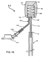
- the part 70 for subcutaneous identification comprises a channel 150 internal “U” (or “L”) shaped opening into two orifices 152 and 154 preferably arranged on the same face of the part 70, the "U” can be more or less open.
- a hollow metal tube 160 is inserted in this channel 150 and exits through the two orifices, on one side to be connected to the supporting rod 20, and on the other side to be connected to a flexible catheter 130 infusion set placed under the patient's skin and connected to an implantable site 140, as in FIG. 12.
- the locating part 70 thus represented is therefore devoid of means of damping the constraints and makes only relay office in order to allow the transit of a product of treatment between the distal end 24 of the support rod 20 and the site implantable 140.
- the carrier rod 20 hollow can be connected directly to the implantable site 140 while passing through the tracking part 70.
- This solution avoids connections between the different hollow parts (piston rod, flexible catheter, rod carrier), these connections may give way or leak and be sources of problems.
- the support rod 20 has one or more curvature (s) 29 (elbow) at the level of the locating part.
- this support rod 20 is preferably inserted into a sleeve (not shown) or preferably directly in a preformed cavity at the inside of the tracking part so as to impose the curvature desired.
- the filter 40 may be directly fixed to the distal end 24 of the rod 20 (therefore without pusher) and arrange the bellows 30 or the spring 80 / envelope 90 assembly in the middle part of the rod 20, which will therefore be in two sections separated by the "absorption means".
- the different means of damping axial stresses can be combined with each other.
- the solution to bellows (or spring) disposed at the distal end of the rod 20 can be combined with a subcutaneous tracking part 70 provided with a means absorption of axial stresses.
- the bellows 30 (or even possibly the flexible envelope 80) can be fitted with an axial guidance system, such as for example a series plastic or metal rings, crimped inside the bellows and regularly spaced along the push rod 50 around which they can slide.
- an axial guidance system such as for example a series plastic or metal rings, crimped inside the bellows and regularly spaced along the push rod 50 around which they can slide.
- the bellows 30 will not rub against the push rod by bending (buckling type sag) during its compression, which will prevent premature degradation (wear) of it and / or a seizure phenomenon which could hinder the absorption of constraints or even move the filter.
Abstract
Description
L'invention se rapporte au domaine des dispositifs à usage médical implantable dans un conduit anatomique.The invention relates to the field of devices for use implantable in an anatomical canal.
Précisément, il s'agit d'un dispositif comprenant une tige flexible bio-compatible présentant un axe le long duquel elle s'étend, hors contrainte, de façon rectiligne, ladite tige ayant une longueur selon cet axe, une extrémité distale et une extrémité proximale.Specifically, it is a device comprising a flexible rod bio-compatible having an axis along which it extends, without constraint, in a straight line, said rod having a length along this axis, a distal end and a proximal end.
Ce type de tige présente actuellement certains inconvénients et ne donne pas entière satisfaction, aussi bien au praticien qui la manipule qu'au patient à l'intérieur du corps duquel elle est placée. En particulier, en cas de mouvement du patient (passage de la position assise à la position couchée, voire à la position foetale, et réciproquement), la tige a tendance à s'adapter à la configuration du conduit (courbure) à l'intérieur duquel elle est introduite et à se déplacer dans celui-ci de telle sorte que ses extrémités ne restent pas en place, ce qui peut être gênant. Il existe donc un problème de stabilité et de maintien en place de ce type de tiges lorsqu'elles sont positionnées à un endroit déterminé d'implantation à l'intérieur du corps d'un patientThis type of rod currently has certain drawbacks and does not not entirely satisfactory, both to the practitioner who handles it and to patient inside the body of which it is placed. In particular, in the event of movement of the patient (change from sitting to lying position, even in the fetal position, and vice versa), the stem tends to adapt the configuration of the duct (curvature) inside which it is introduced and to move in it so that its ends don't not stay in place, which can be annoying. There is therefore a problem of stability and holding in place of this type of rods when they are positioned at a specific location inside the body of a patient
Pour résoudre cela, il est proposé que la tige soit munie d'au moins un moyen d'absorption des contraintes axiales disposé selon son axe et qui est distinct de celle-ci tout en étant lié à elle, de sorte que son extrémité proximale ne se déplace sensiblement pas axialement, une fois la tige parvenue à l'endroit déterminé d'implantation dans le conduitTo resolve this, it is proposed that the rod be provided with less a means for absorbing axial stresses arranged along its axis and which is distinct from it while being linked to it, so that its end proximal does not move substantially axially, once the rod reached the determined location in the duct
On précise ici que sera « rectiligne » toute tige présentant, au repos, une direction générale d'extension droite suivant son axe et qui ne présente donc pas localement, au moins à l'emplacement de son moyen d'absorption des contraintes, une courbure marquée (sinuosité) pouvant servir d'amortisseur (comme dans n° FR-A-2 715 827).It is specified here that any rod exhibiting, at the rest, a general direction of straight extension along its axis and which does not therefore not present locally, at least at the location of its means stress absorption, a marked curvature (sinuosity) which can serve as a shock absorber (as in No. FR-A-2 715 827).
En relation avec une telle tige, l'invention concerne en particulier les dispositifs pour l'implantation temporaire d'un implant vasculaire, tel qu'un filtre sanguin. Un tel filtre est en particulier décrit dans EP-A-521 522 ou US-A-5 634 942.In connection with such a rod, the invention relates in particular devices for the temporary implantation of a vascular implant, such than a blood filter. Such a filter is described in particular in EP-A-521 522 or US-A-5,634,942.
L'expérience a montré que lors de l'implantation d'un implant, et en particulier d'un filtre sanguin, il arrive, en raison du flux sanguin, que celui-ci se déplace axialement dans le vaisseau lorsqu'il est dépourvu de moyen d'accrochage à la paroi du vaisseau. On a aussi remarqué que, durant de la période d'implantation temporaire de l'implant, ce dernier peut, suite aux mouvements et changements de position du patient, se déplacer dans le conduit voire s'arracher s'il a commencé à être recouvert d'agrégats cellulaires.Experience has shown that when implanting an implant, and especially a blood filter, it happens, because of the blood flow, that this moves axially in the vessel when it is devoid of means of attachment to the vessel wall. We also noticed that during of the temporary implantation period, the implant can, following movements and position changes of the patient, move in the leads or even tears off if it has started to be covered with aggregates cellular.
Ainsi, l'invention se rapporte à un dispositif pour la mise en place de façon temporaire à l'intérieur d'un conduit anatomique d'un patient d'un implant comprenant une structure radialement expansible, et en particulier d'un filtre sanguin, ledit dispositif comprenant en particulier la tige telle que présentée ci-avantThus, the invention relates to a device for the establishment temporarily inside an anatomical canal of a patient of a implant comprising a radially expandable structure, and in particular a blood filter, said device comprising in particular the rod such as presented above
Lorsque l'on veut mettre en place l'implant temporairement dans le corps du patient, on peut souhaiter, après avoir introduit la tige à l'intérieur du conduit anatomique du patient, placer sous sa peau l'extrémité proximale de la tige à l'autre bout de laquelle est disposé l'implant. Dans ce cas, l'adaptation de courbure de la tige en cas de mouvement du patient peut aussi provoquer un déplacement douloureux de son extrémité proximale, là où elle sera liée à une pièce sous-cutanée de repérage (voir EP-A-521 222), voire d'une pièce destinée à assurer des opérations d'injection/prélèvement (via une chambre implantable, comme dans FR-A-2 697 995).When you want to place the implant temporarily in the patient's body, one may wish, after having introduced the rod to inside the patient's anatomical canal, place the end under his skin proximal of the rod at the other end of which is placed the implant. In this case, the adaptation of curvature of the rod in the event of movement of the patient can also cause a painful displacement of its proximal end, there where it will be linked to a subcutaneous locating piece (see EP-A-521 222), or even a part intended for injection / sampling operations (via an implantable chamber, as in FR-A-2 697 995).
Pour résoudre cela, le moyen, ou l'un au moins de ces moyens, d'absorption des contraintes axiales pourra être disposé vers l'extrémité proximale de la tige, là où elle celle-ci est liée à ladite pièce sous-cutanée, laquelle est donc repérable par palpation à travers la peau du patientTo resolve this, the means, or at least one of these means, axial stress absorption can be arranged towards the end proximal to the stem, where it is linked to said subcutaneous part, which can therefore be identified by palpation through the patient's skin
Toujours dans le but de résoudre le problème présenté ci-avant, l'invention prévoit en particulier que ladite pièce de repérage soit équipée dudit moyen d'amortissement des contraintes, en particulier sous la forme d'un dispositif à piston et/ou éventuellement ressortStill with the aim of solving the problem presented above, the invention provides in particular that said locating part is equipped of said means for damping stresses, in particular in the form a piston and / or possibly spring device
Selon un aspect complémentaire, le moyen d'absorption dès contraintes axiales pourra comprendre un soufflet pouvant s'allonger ou se raccourcir axialement. Cette solution simple garantit une absorption progressive et continue, peut s'adapter aussi bien à une tige pleine que creuse, et peut être positionnée à n'importe quel endroit de celle-ci.According to a complementary aspect, the means of absorption from axial stresses may include a bellows that can lengthen or expand axially shorten. This simple solution guarantees absorption progressive and continuous, can adapt to both a full stem and hollow, and can be positioned anywhere therein.
Selon une alternative, le moyen d'absorption des contraintes pourra comprendre un ressortAccording to an alternative, the means of stress absorption may include a spring
Selon une autre alternative éventuellement complémentaire des deux précédentes, le moyen d'absorption des contraintes axiales pourra comprendre un piston. Cette solution offre en plus une tenue transversale du moyen d'absorption des contraintes.According to another alternative, possibly complementary to two previous, the means of absorption of the axial stresses could include a piston. This solution also offers transverse holding of the means of stress absorption.
En particulier si l'implant est un filtre comprenant une tête de laquelle partent des pattes expansibles radialement, le moyen d'absorption des contraintes axiales pourra être fixé vers l'extrémité distale de la tige. On concentre ainsi l'effet d'amortissement dans une zone critique, c'est-à-dire la zone de pose de l'implant. Ainsi, les contraintes qui s'exercent sur l'implant sont immédiatement compensées par le moyen d'absorption, ces contraintes n'étant alors pas (ou très peu) transmises à la tige.In particular if the implant is a filter comprising a which leave radially expandable legs, the absorption means axial stresses can be fixed towards the distal end of the rod. We thus concentrates the damping effect in a critical area, i.e. the implant placement area. Thus, the stresses exerted on the implant are immediately compensated by the absorption means, these constraints then not (or very little) transmitted to the rod.
De façon à résoudre les difficultés que l'on peut avoir à implanter et retirer l'implant, le piston pourra comprendre une seconde tige-poussoir montée coulissante à l'intérieur de la première tige par l'intermédiaire de cette dernière est liée à l'implant.In order to resolve the difficulties that we may have to implant and remove the implant, the piston may include a second push rod sliding mounted inside the first rod by means of the latter is linked to the implant.
De façon à améliorer le coulissement relatif du piston à l'intérieur de la tige, le dispositif pourra comprendre en outre un système de guidage et de butée pour limiter son débattement axial à l'intérieur de la tige.In order to improve the relative sliding of the piston inside of the rod, the device may further comprise a guidance system and stop to limit its axial clearance inside the rod.
En particulier, ce système pourra comprendre une première bague fixée à l'intérieur de la première tige et dont le diamètre interne est légèrement supérieur au diamètre externe du piston, et seconde une bague (ou protubérance) liée au piston et dont le diamètre externe est légèrement inférieur au diamètre interne de la tige.In particular, this system may include a first ring fixed inside the first rod and whose internal diameter is slightly greater than the external diameter of the piston, and second a ring (or protuberance) linked to the piston and whose external diameter is slightly less than the internal diameter of the rod.
Indépendamment des problèmes cités précédemment d'amortissement des contraintes axiales, un autre problème se pose en relation avec l'utilisation d'un site implantable à relier à un dispositif à usage médical propre à être introduit dans un conduit d'un corps humain ou animal vivant, tel qu'un cathéter.Regardless of the problems mentioned above damping of axial stresses, another problem arises in relationship with the use of an implantable site to be linked to a device for use suitable for being introduced into a duct of a human body or living animal, such as a catheter.
A toutes fins utiles, on notera que l'extrémité «distale» des éléments du dispositif désigne l'extrémité qui doit être implantée le plus profondément dans le corps du patient, l'extrémité «proximale» étant l'extrémité opposée située près de la surface de la peau (voire à l'extérieur).For all intents and purposes, it will be noted that the "distal" end of the elements of the device indicates the end which must be located the most deep into the patient's body, the "proximal" end being the opposite end located near the surface of the skin (or even outside).
L'invention et sa mise en oeuvre apparaítront encore plus clairement à l'aide de la description qui va suivre, faite en référence aux dessins dans lesquels:
- la figure 1 est une vue générale d'un dispositif conforme à l'invention,
- les figures 2 et 3 sont des vues de détail en coupe du dispositif de la figure 1,
- les figures 4 et 5 sont des vues de détail en coupe d'une variante de réalisation du dispositif de la figure 1,
- les figures 6 et 7 sont des vues en coupe d'un détail d'une autre variante de réalisation du dispositif de la figure 1,
- la figure 8 est une vue en coupe schématique du corps d'un patient dans lequel est implanté le dispositif de la figure 1,
- les figures 9 et 10 montrent certains des principaux moyens utilisés pour la mise en place ou le retrait du dispositif de l'invention.
- la figure 11 est une variante de réalisation du dispositif dans laquelle la pièce de repérage sous-cutané est équipée d'un moyen d'amortissement des contraintes axiales,
- la figure 12 est une variante de la figure 11 dans laquelle la pièce de repérage sous-cutané a également une fonction de relais pour un site implantable,
- la figure 13 est une variante de la figure 12 dans laquelle la pièce de repérage sert uniquement de relais et n'est plus munie d'un moyen d'amortissement des contraintes axiales,
- la figure 14 est une variante de la figure 13, et
- la figure 15 est autre variante de réalisation.
- FIG. 1 is a general view of a device according to the invention,
- FIGS. 2 and 3 are detailed section views of the device in FIG. 1,
- FIGS. 4 and 5 are detailed section views of an alternative embodiment of the device of FIG. 1,
- FIGS. 6 and 7 are sectional views of a detail of another alternative embodiment of the device of FIG. 1,
- FIG. 8 is a schematic sectional view of the body of a patient in which the device of FIG. 1 is implanted,
- Figures 9 and 10 show some of the main means used for the establishment or removal of the device of the invention.
- FIG. 11 is an alternative embodiment of the device in which the subcutaneous locating piece is equipped with a means of damping the axial stresses,
- FIG. 12 is a variant of FIG. 11 in which the subcutaneous locating piece also has a relay function for an implantable site,
- FIG. 13 is a variant of FIG. 12 in which the locating part only serves as a relay and is no longer provided with a means for damping axial stresses,
- FIG. 14 is a variant of FIG. 13, and
- Figure 15 is another alternative embodiment.
L'un des intérêts de l'utilisation de ce dispositif étant en particulier de pouvoir améliorer les conditions d'implantation des filtres sanguins temporaires, on ne décrira ci-après l'invention que dans le cadre d'une telle application, même s'il doit être clair qu'elle peut s'appliquer à d'autres implants médicaux, vasculaires ou non (stents par exemple).One of the benefits of using this device is particular to be able to improve the installation conditions of the filters temporary blood, the invention will only be described below in the context of such an application, even if it must be clear that it can apply to other medical implants, vascular or not (stents for example).
Sur la figure 1 on voit donc illustré dans son ensemble une unité
temporaire de filtration 10, d'axe général sensiblement rectiligne xx',
pouvant être mise en place par voie percutanée (méthode de
« SELDINGER »), ou par dénudation.In Figure 1 we therefore see illustrated as a whole a unit
Ce dispositif 10 comprend essentiellement une tige souple 20
rectiligne bio-compatible, d'axe xx' et de longueur L selon cet axe, avec une
extrémité proximale 22 et une extrémité distale 24 opposée. Cette tige 20
pourra être pleine ou de préférence présenter un passage intérieur 25 pour
former alors un cathéter. Les figures 2 à 5 représentent le détail D de la
figure 1.This
A son extrémité proximale 22, la tige 20 est ici reliée à une pièce 70
sous-cutanée (voir figures 6 et 7) sensiblement fixe en position, appelée aussi
« olive de repérage », qui permet, une fois ladite pièce 70 enfouie
entièrement sous la peau du patient par exemple en zone sous-clavière, de
faciliter le repérage de l'extrémité proximale de la tige 20 par palpation à
travers la peau (voir EP-A-211 522). Si la tige 20 est creuse, en alternative, la
pièce 70 sous-cutanée pourra être une chambre implantable de distribution
d'un produit traitant, telle que décrite dans FR-A-2 697 995. Cette variante de
réalisation est illustrée en figure 15.At its
Le dispositif 10 comprend aussi un soufflet 30 de préférence en
silicone, qui présente une extrémité proximale 32 et une extrémité distale 34.
Son extrémité proximale 32 est fixée, par exemple par collage ou sertissage,
autour de l'extrémité distale 24 de la tige 20. Ce soufflet 30 présente une
longueur (l) initiale dans son état libre (état ni comprimé ni étiré axialement)
selon l'axe xx' de la tige 20 égale à environ un dixième de la longueur totale
L de cette dernière, c'est-à-dire comprise entre environ 5 et 15 centimètres, ce
soufflet 30 pouvant s'étendre ou rétrécir axialement jusqu'à environ 50% de
sa longueur initiale. De préférence, le soufflet 30 est étanche au liquide et est
de type élastiquement déformable, c'est-à-dire qu'après avoir appliqué sur
ses deux extrémités une contrainte axiale de compression ou de traction, il
revient de lui-même dans sa position de repos où il présente sa longueur (1)
initiale.The
A son extrémité distale 34, le soufflet 30 est aussi fixé à un filtre
sanguin 40 en métal bio-compatible (acier inoxydable) qui présente, en
position déployée, une forme générale de corolle conique. Ce filtre 40
comprend des pattes 45 dépourvues de tout moyen d'accrochage (crochet
par exemple) au vaisseau et toutes issues d'une tête 46 commune autour de
laquelle est fixée le soufflet 30 par l'intermédiaire d'une bague 48. Ces pattes
45 pourront en particulier être auto-expansibles radialement, hors
contraintes, pour avoir naturellement tendance à se déployer jusqu'à leur
extrémité libre vienne au contact de la paroi du vaisseau.At its
Le dispositif 10 comprend également une seconde tige 50, faisant
office de piston et de poussoir, disposée à l'intérieur de la tige 20 de façon à
pouvoir coulisser longitudinalement à l'intérieur de celle-ci. Cette tige-poussoir
50 présente une extrémité distale 54 fixée à la tête 46 du filtre 40, et
une extrémité proximale 52 autour de laquelle est sertie une première bague
62 coopérant avec une seconde bague 64 fixée à l'intérieur de la tige 20, à son
extrémité distale 34. Ces deux bagues 62 et 64 servent à guider la tige-poussoir
50 à l'intérieur de la tige 20 et à limiter son débattement (d) axial en
faisant office de butée lorsque le soufflet 30 se comprime ou s'étend.The
Le filtre 40 étant destiné à être implanté à l'intérieur d'un vaisseau
sanguin, on a constaté, dans les dispositifs de l'art antérieur, qu'il était
particulièrement soumis à des contraintes mécaniques occasionnées par les
mouvements du patient. Or de telles contraintes tendent à se propager le
long de la tige 20. La pièce 70 de repérage, de même que le filtre 20 lui-même,
peuvent donc être soumis à un déplacement, ce qui est peut
confortable pour le patient et risque d'entraíner des complications annexes.The
Ainsi, le soufflet 30 permet d'absorber ces contraintes axiales et de
compenser des déplacements intempestifs du filtre ou de la pièce 70 de
repérage. Comme on peut le voir sur la figure 3, où l'on considère que le
filtre est implanté dans le vaisseau (voir aussi figure 8), le soufflet 30 est dans
un état libre dans lequel le poussoir 50 peut se déplacer axialement. Il peut
donc s'étirer ou se comprimer axialement au gré des mouvements du
patient, et ce sans que le filtre 40 ou l'extrémité proximale 22 de la tige 20 ne
se déplace axialement, en particulier lorsque le filtre 40 est recouvert d'un
agrégat cellulaire ou lorsqu'il est partiellement coincé. Le déplacement du
soufflet 30 entraíne évidemment celui de la tige-poussoir 50 à l'intérieur de
la tige 20, ce qui contribue à améliorer l'absorption des contraintes axiales en
évitant qu'elles se transmettent à la première tige 20. On peut donc noter que
cette seconde tige-poussoir 50 constitue en elle-même un moyen
d'absorption des contraintes axiales, sous la forme d'un piston.Thus, the
Les figures 4 et 5 montrent une variante de réalisation du
dispositif des figures 2 et 3 utilisable à l'une et/ou l'autre des extrémités de
la tige 20. Dans cette solution, le moyen d'absorption des contraintes
comprend une enveloppe 80 (ou un manchon) étanche, réalisée dans un
matériau bio-compatible très fin pouvant en particulier se déformer et se
plier sur lui-même sans se percer, tel que du silicone, et un ressort hélicoïdal
90. L'enveloppe 80 est fixée, comme le soufflet 30, à la tête 46 du filtre 40
d'une part et à l'extrémité distale 24 de la tige 20 d'autre part, de façon à
rendre le dispositif 10 étanche au fluide circulant dans le vaisseau. Le ressort
90 est monté à l'intérieur de l'enveloppe 80 et entoure la tige-poussoir 50,
laquelle est munie d'une bague 62. Ce ressort 90 prend appui, dans un état
au moins partiellement comprimé axialement (en particulier lors de
l'implantation comme illustré sur la figure 4), d'une part contre l'extrémité
distale 24 de la tige 20 et d'autre part contre le prolongement 48 de la tête du
filtre. L'ensemble comprenant l'enveloppe 80 et le ressort 90 ont ainsi la
même fonction d'absorption des contraintes que le soufflet 30 ou la tige-poussoir
50 présentés précédemmentFigures 4 and 5 show an alternative embodiment of the
device of FIGS. 2 and 3 usable at one and / or the other of the ends of
the
Les figures 6 et 7 montrent une autre variante de réalisation,
utilisable de préférence en collaboration avec l'une des deux présentée ci-avant
et disposée à l'extrémité proximale de la tige 20, à l'endroit où se
trouve la pièce 70 de repérage. Dans cette solution, la pièce de repérage 70
est montée sur un tube 72, plein ou creux, qui pénètre à l'intérieur de la tige
20 sur une certaine longueur, par exemple comprise entre environ 2 et 12
centimètres. Ce tube 72, faisant office de piston, comprend un système de
guidage axial et de butée comprenant une excroissance 74 (ou une première
bague) liée à son extrémité distale et dont le diamètre externe est légèrement
inférieur au diamètre interne de la tige 20 coopérant avec une seconde bague
76 sertie à l'intérieur de l'extrémité proximale de la tige 20 et dont le
diamètre interne est légèrement supérieur au diamètre externe du tube 72.
Enfin, un soufflet 30 étanche relie l'extrémité proximale 22 de la tige 20 à la
pièce 70 de repérage, laquelle est maintenue à la tige 20, par exemple par un
clou 78.Figures 6 and 7 show another alternative embodiment,
preferably usable in collaboration with one of the two presented above
and disposed at the proximal end of the
Sur la figure 7, on a remplacé le soufflet 30 par une combinaison
comprenant un ressort hélicoïdal 90 et une enveloppe 80 souple et étanche
ayant la même fonction. In FIG. 7, the
Dans ces deux variantes, les contraintes axiales qui s'exercent sur
l'extrémité distale 24 de la tige 20 et qui parcourent celle-ci jusqu'à son
extrémité proximale 22 sont absorbées par le piston 72 et par le soufflet 30 ou
le ressort 90. Ainsi, la pièce 70 de repérage sous-cutané ne se déplace pas
sous la peau du patientIn these two variants, the axial stresses exerted on
the
L'implantation jusqu'à la zone d'implantation (ZI) (ou le retrait)
de l'unité 40 de filtration sanguine s'effectue comme dans FR-A-2 715 827,
par voie endoluminale percutanée, si nécessaire par l'intermédiaire d'une
gaine introductrice 100.Implantation to the implantation zone (ZI) (or withdrawal)
of the
Une fois la gaine 100 en position, elle sert de guide pour la mise
en place du filtre 40, lequel est habituellement préconditionné à l'état
radialement restreint de ses pattes dans une sorte de seringue 120 de
conditionnement (non représentée) vissée sur l'embout proximal 102 de la
gaine qui débouche hors du corps du patientOnce the
Pour faire descendre l'ensemble comprenant la tige 20, le filtre 40
solidaire de sa tige-poussoir 50 et le soufflet 30, le praticien agit sur la tige-poussoir
50 par l'extérieur du corps du patient à l'aide d'un mandrin 110
(tige de préférence pleine et plus rigide que la tige). Le soufflet 30 (ou
l'enveloppe 80) s'étire alors axialement tandis que le filtre 40 se libère et
s'expanse radialement, hors de la gaine 100. Le praticien retire alors le
mandrin 110, coupe la tige 20 à longueur et vient fixer à son extrémité
proximale 12 la pièce 70 à l'aide du clou 78 avant d'enfouir le tout dans les
tissus du patient et de refermer la voie d'accès.To lower the assembly comprising the
Une fois le filtre 40 en place, le moyen d'absorption des
contraintes axiales (piston, soufflet, ressort) remplit sa fonction et empêche
au filtre et/ou à la pièce 70 de se déplacer axialement à l'intérieur du
vaisseau, en particulier lorsque le patient change de position.Once the
Pour des questions de compréhension, les échelles des figures 11 à 14 qui suivent n'ont pas été respectées For questions of understanding, the scales of Figures 11 to 14 which follow were not respected
Une autre variante de réalisation est représentée sur la figure 11
où seulement l'extrémité proximale de la tige 20 est dessinée. La pièce 70 de
repérage sous-cutané, de préférence en silicone, présente une cavité interne
90 à l'intérieur de laquelle se trouve un ressort 100 de compression prenant
contre le fond 92 de la cavité 90 et sur lequel repose un piston 120 en métal
biocompatible (acier inoxydable) ou matériau plastique comprenant une tête
122 sensiblement en forme de disque et une tige 124, de préférence pleine.
Cette tige 124 de piston est fixée à l'extrémité proximale 22 de la tige 20
porteuse du filtre 40, par exemple par sertissage, ou collage ou toute autre
technique connue. Le ressort 100 peut se comprimer axialement suivant une
course E. Ainsi, lorsque le dispositif 10 est implanté dans le corps du patient
et que la pièce 70 de repérage sous-cutané est disposée sous la peau, par
exemple en zone sous-clavière, le ressort 100 absorbe élastiquement les
contraintes axiales pouvant survenir en s'écrasant, comme cela a déjà été
exposé précédemment Ainsi, la pièce 70 de repérage et le filtre 40 peuvent
demeurer à leur endroit respectif d'implantation.Another alternative embodiment is shown in Figure 11
where only the proximal end of the
Sur la figure 12, la pièce 70 de repérage comprend toujours une
cavité interne 90 à l'intérieur de laquelle est logée un ressort 100 sur lequel
repose un piston 120 relié, par l'intermédiaire de sa tige 124, à la tige 20
porteuse du filtre 40 de la même façon que précédemment La tige 124 du
piston est creuse et forme un coude 125 (courbure prononcée) à l'endroit de
la tête 122 du piston. Cette tige 124 est liée, par une « branche » 126, à un
cathéter 130 souple, lequel cathéter est implanté sous la peau du patient et
est connecté à un site implantable 140 (appelé aussi chambre implantable) de
type connu (voir brevet FR-A-2 697 995) également situé sous la peau par au
niveau de la cage thoracique. Ce site implantable 140 est adapté pour que
l'on puisse piquer dans sa paroi 142 auto-obturante (par exemple en silicone)
une seringue contenant un produit traitant à acheminer à l'intérieur du
vaisseau jusqu'au filtre, dans l'optique par exemple de détruire un caillot
sanguin capturé. Ainsi, la pièce 70 de repérage sous-cutané, en plus de
comprendre un moyen d'amortissement des contraintes axiales, sert de relais
à un site implantable. Cette solution évite d'avoir à fixer le site implantable
140 directement à l'extrémité proximale 22 de la tige porteuse 20 (ce qui ne
permet pas d'amortir les contraintes axiales) tout en procurant un confort
amélioré au patientIn FIG. 12, the locating
Dans ces deux variantes de réalisation, le moyen d'amortissement
des contraintes axiales peut être autre qu'un ressort 100 de compression, par
exemple un ressort à lame, voire un dispositif d'amortissement par fluide
(air ou liquide), auquel cas le piston sera monté de façon étanche dans la
cavité.In these two alternative embodiments, the damping means
axial stresses can be other than a
On notera que l'utilisation d'une tige flexible biocompatible telle
que représentée sur les figures 1 à 12 peut se faire sans la présence d'un
quelconque implant à son extrémité distale 22. Ainsi, comme cela est illustré
sur la figure 15, il est possible de relier un cathéter 20 d'injection à une
chambre implantable 140 (identique à celle de la figure 12) fixée sous la peau
du patient et de munir ledit cathéter 20 d'un soufflet 30. Les changements de
configurations du vaisseau dans lequel le cathéter est implanté sont
compensés par les moyens d'amortissement 30, permettant ainsi au cathéter
de rester positionné à un endroit déterminé d'implantation à l'intérieur du
conduit du patient Ainsi, son extrémité proximale 22 ne se déplace
sensiblement pas axialement, ceci étant d'autant plus vrai si cette extrémité
proximale de la tige flexible concernée est directement fixée à la peau du
patient ou si elle est pourvue d'un dispositif de repérage sous-cutané tel que
l'olive des figures 6 et 7 ou 11 et 12.Note that the use of a flexible biocompatible rod such
that shown in Figures 1 to 12 can be done without the presence of a
any implant at its
Indépendamment des problèmes résolus par les dispositifs
présentés sur les figures 1 à 12 et 15 en relation avec l'amortissement des
contraintes axiales, se pose un problème distinct relatif à l'utilisation d'un
site implantable tel que décrit dans le brevet FR-A-2 697 995. En effet, il peut
y avoir un problème pour relier un tel site implantable à l'extrémité
proximale 22 de la tige 20, en particulier lorsque l'on souhaite pouvoir
repérer cette extrémité proximale 22 sous la peau du patient tout en assurant
une bonne assise audit site.Regardless of the problems solved by the devices
presented in Figures 1 to 12 and 15 in relation to the amortization of
axial constraints, there is a distinct problem relating to the use of a
implantable site as described in patent FR-A-2 697 995. Indeed, it can
there is a problem to connect such an implantable site at the end
proximal 22 of
La figure 13 présente une solution à ce problème spécifique. Dans
cette solution, la pièce 70 de repérage sous-cutané comporte un canal 150
interne en forme de « U » (ou de « L ») débouchant en deux orifices 152 et
154 disposés de préférence sur une même face de la pièce 70, le «U»
pouvant être plus ou moins ouvert. Un tube 160 métallique creux est inséré
dans ce canal 150 et sort par les deux orifices, d'un côté pour être connecté à
la tige porteuse 20, et de l'autre côté pour être connecté à un cathéter souple
130 de perfusion placé sous la peau du patient et relié à un site implantable
140, comme dans la figure 12. La pièce 70 de repérage ainsi représentée est
donc dépourvue de moyen d'amortissement des contraintes et fait
uniquement office de relais de façon à permettre le transit d'un produit de
traitement entre l'extrémité distale 24 de la tige porteuse 20 et le site
implantable 140.Figure 13 presents a solution to this specific problem. In
this solution, the
Selon une alternative représentée sur la figure 14, la tige porteuse
20 creuse peut être reliée directement au site implantable 140 tout en
transitant par la pièce 70 de repérage. Cette solution évite les connexions
entre les différentes parties creuses (tige du piston, cathéter souple, tige
porteuse), ces connexions pouvant céder ou fuir et être sources de
problèmes. Ainsi, la tige porteuse 20 présente une ou plusieurs courbure(s)
29 (coude) au niveau de la pièce de repérage. Pour éviter les phénomènes de
plicatures, cette tige porteuse 20 est de préférence insérée dans un manchon
(non représenté) ou de préférence directement dans une cavité préformée à
l'intérieur de la pièce de repérage de façon à lui imposer la courbure
souhaitée. Ainsi, il est toujours possible d'injecter un produit du site
implantable 140 jusqu'à l'extrémité distale 24 de la tige porteuse 20 tout en
conservant une pièce 70 de repérage utilisable lorsque l'on veut retirer du
corps du patient le filtre 140 implanté temporairement. According to an alternative shown in Figure 14, the
Bien entendu, l'invention n'est nullement limitée aux modes de réalisation présentés ci-dessus.Of course, the invention is in no way limited to the modes of realization presented above.
Ainsi, on pourra prévoir que le filtre 40 soit directement fixé à
l'extrémité distale 24 de la tige 20 (donc sans poussoir) et disposer le soufflet
30 ou l'ensemble ressort 80/enveloppe 90 en partie médiane de la tige 20,
laquelle sera donc en deux tronçons séparés par le « moyen d'absorption ».Thus, provision may be made for the
On peut également envisager d'utiliser ce dispositif dans d'autres conduits tels que l'oesophage ou la trachée artère, ou avec d'autres types d'implants (stent).We can also consider using this device in other ducts such as the esophagus or trachea artery, or with other types implants (stent).
Les différents moyens d'amortissement des contraintes axiales
peuvent indifféremment être combinés entre eux. En particulier, la solution à
soufflet (ou ressort) disposé à l'extrémité distale de la tige 20 peut être
combinée avec une pièce 70 de repérage sous-cutané munie d'un moyen
d'absorption des contraintes axiales.The different means of damping axial stresses
can be combined with each other. In particular, the solution to
bellows (or spring) disposed at the distal end of the
Enfin, le soufflet 30 (voire éventuellement l'enveloppe souple 80)
peut être muni d'un système de guidage axial, tel par exemple qu'une série
de bagues en matière plastique ou en métal, serties à l'intérieur du soufflet et
régulièrement espacées le long de la tige-poussoir 50 autour de laquelle elles
peuvent coulisser. Ainsi, le soufflet 30 ne viendra pas frotter contre la tige-poussoir
en se courbant (fléchissement de type flambage) lors de sa
compression, ce qui évitera une dégradation prématurée (usure) de celui-ci
et/ou un phénomène de grippage pouvant gêner l'absorption des
contraintes voire déplacer le filtre.Finally, the bellows 30 (or even possibly the flexible envelope 80)
can be fitted with an axial guidance system, such as for example a series
plastic or metal rings, crimped inside the bellows and
regularly spaced along the
Claims (11)
Applications Claiming Priority (4)
| Application Number | Priority Date | Filing Date | Title |
|---|---|---|---|
| FR9801835A FR2774893A1 (en) | 1998-02-16 | 1998-02-16 | Medical implant with biocompatible flexible tube |
| FR9801835 | 1998-02-16 | ||
| FR9804685 | 1998-04-15 | ||
| FR9804685A FR2774895B1 (en) | 1998-02-16 | 1998-04-15 | MEDICAL DEVICE COMPRISING A ROD PROVIDED WITH A MEANS FOR ABSORBING AXIAL CONSTRAINTS |
Publications (1)
| Publication Number | Publication Date |
|---|---|
| EP0935975A1 true EP0935975A1 (en) | 1999-08-18 |
Family
ID=26234142
Family Applications (1)
| Application Number | Title | Priority Date | Filing Date |
|---|---|---|---|
| EP99400256A Withdrawn EP0935975A1 (en) | 1998-02-16 | 1999-02-04 | Medical device having a shaft provided with absorbtion means for axial stress |
Country Status (3)
| Country | Link |
|---|---|
| US (1) | US6152931A (en) |
| EP (1) | EP0935975A1 (en) |
| FR (1) | FR2774895B1 (en) |
Cited By (7)
| Publication number | Priority date | Publication date | Assignee | Title |
|---|---|---|---|---|
| FR2814670A1 (en) * | 2000-10-02 | 2002-04-05 | Braun Medical | Implantable blood clot filter has catheter of varying rigidity along its length and constant for at least half its length from distal end |
| US8057507B2 (en) | 2009-01-16 | 2011-11-15 | Novate Medical Limited | Vascular filter |
| US8162970B2 (en) | 2006-07-19 | 2012-04-24 | Novate Medical Limited | Vascular filter |
| US8668713B2 (en) | 2009-01-16 | 2014-03-11 | Novate Medical Limited | Vascular filter device |
| US9833304B2 (en) | 2009-01-16 | 2017-12-05 | Novate Medical Limited | Vascular filter device |
| US10624731B2 (en) | 2009-01-16 | 2020-04-21 | Novate Medical Limited | Vascular filter system |
| US10687930B2 (en) | 2013-03-15 | 2020-06-23 | Novate Medical Limited | Vascular filter device |
Families Citing this family (39)
| Publication number | Priority date | Publication date | Assignee | Title |
|---|---|---|---|---|
| US5681347A (en) * | 1995-05-23 | 1997-10-28 | Boston Scientific Corporation | Vena cava filter delivery system |
| US6398266B1 (en) | 1999-09-22 | 2002-06-04 | Ballard Medical Products | Collapse resistant popoid connector |
| US6755794B2 (en) * | 2000-04-25 | 2004-06-29 | Synovis Life Technologies, Inc. | Adjustable stylet |
| USD473941S1 (en) | 2001-08-27 | 2003-04-29 | Kimberly-Clark Worldwide, Inc. | Flexible connecting device |
| USD466607S1 (en) | 2001-08-27 | 2002-12-03 | Kimberly-Clark Worldwide, Inc. | Flexible connector |
| USD476731S1 (en) | 2001-08-27 | 2003-07-01 | Kimberly-Clark Worldwide, Inc. | Bendable connector |
| USD486909S1 (en) | 2001-08-27 | 2004-02-17 | Kimberly-Clark Worldwide, Inc. | Bendable connecting device |
| US20050027309A1 (en) * | 2003-06-17 | 2005-02-03 | Samuel Shiber | Guidewire system |
| ATE526052T1 (en) * | 2004-03-30 | 2011-10-15 | Lilly Co Eli | MEDICATION DISPENSING DEVICE HAVING A GEAR SET WITH AN OPENING FOR RECEIVING A DRIVE ELEMENT |
| WO2006042114A1 (en) | 2004-10-06 | 2006-04-20 | Cook, Inc. | Emboli capturing device having a coil and method for capturing emboli |
| US20060089569A1 (en) * | 2004-10-26 | 2006-04-27 | Soukup Thomas M | Articulator with adjustable stiffness distal portion |
| WO2006055047A2 (en) * | 2004-11-18 | 2006-05-26 | Mark Adler | Intra-bronchial apparatus for aspiration and insufflation of lung regions distal to placement or cross communication and deployment and placement system therefor |
| US8221446B2 (en) | 2005-03-15 | 2012-07-17 | Cook Medical Technologies | Embolic protection device |
| US8945169B2 (en) | 2005-03-15 | 2015-02-03 | Cook Medical Technologies Llc | Embolic protection device |
| EP1728530A1 (en) * | 2005-06-01 | 2006-12-06 | Medsafe ASA | Injection syringe with automatically retractable needle |
| US7850708B2 (en) | 2005-06-20 | 2010-12-14 | Cook Incorporated | Embolic protection device having a reticulated body with staggered struts |
| US8109962B2 (en) | 2005-06-20 | 2012-02-07 | Cook Medical Technologies Llc | Retrievable device having a reticulation portion with staggered struts |
| US7766934B2 (en) | 2005-07-12 | 2010-08-03 | Cook Incorporated | Embolic protection device with an integral basket and bag |
| US7771452B2 (en) | 2005-07-12 | 2010-08-10 | Cook Incorporated | Embolic protection device with a filter bag that disengages from a basket |
| US8187298B2 (en) | 2005-08-04 | 2012-05-29 | Cook Medical Technologies Llc | Embolic protection device having inflatable frame |
| US8377092B2 (en) | 2005-09-16 | 2013-02-19 | Cook Medical Technologies Llc | Embolic protection device |
| US8632562B2 (en) | 2005-10-03 | 2014-01-21 | Cook Medical Technologies Llc | Embolic protection device |
| US8182508B2 (en) | 2005-10-04 | 2012-05-22 | Cook Medical Technologies Llc | Embolic protection device |
| US8252017B2 (en) | 2005-10-18 | 2012-08-28 | Cook Medical Technologies Llc | Invertible filter for embolic protection |
| US8216269B2 (en) | 2005-11-02 | 2012-07-10 | Cook Medical Technologies Llc | Embolic protection device having reduced profile |
| US8152831B2 (en) | 2005-11-17 | 2012-04-10 | Cook Medical Technologies Llc | Foam embolic protection device |
| US7892186B2 (en) | 2005-12-09 | 2011-02-22 | Heraeus Materials S.A. | Handle and articulator system and method |
| US20070239198A1 (en) * | 2006-04-03 | 2007-10-11 | Boston Scientific Scimed, Inc. | Filter and wire with distal isolation |
| US8118853B2 (en) * | 2006-06-19 | 2012-02-21 | Cook Medical Technologies Llc | Prosthesis delivery and deployment device |
| US20080125696A1 (en) * | 2006-08-21 | 2008-05-29 | Tycohealthcare Group Lp | Adjustable aspiration device and method of making |
| US20080071307A1 (en) | 2006-09-19 | 2008-03-20 | Cook Incorporated | Apparatus and methods for in situ embolic protection |
| US9901434B2 (en) | 2007-02-27 | 2018-02-27 | Cook Medical Technologies Llc | Embolic protection device including a Z-stent waist band |
| US8007470B2 (en) * | 2007-07-10 | 2011-08-30 | Cook Medical Technologies Llc | Minimally invasive medical device and method for delivery of therapeutic or diagnostic agents into a vessel wall |
| US8252018B2 (en) | 2007-09-14 | 2012-08-28 | Cook Medical Technologies Llc | Helical embolic protection device |
| US9138307B2 (en) | 2007-09-14 | 2015-09-22 | Cook Medical Technologies Llc | Expandable device for treatment of a stricture in a body vessel |
| US8419748B2 (en) | 2007-09-14 | 2013-04-16 | Cook Medical Technologies Llc | Helical thrombus removal device |
| US8313493B2 (en) * | 2008-07-10 | 2012-11-20 | Cook Medical Technologies Llc | Hydraulic guidewire advancement system |
| US8388644B2 (en) | 2008-12-29 | 2013-03-05 | Cook Medical Technologies Llc | Embolic protection device and method of use |
| CN218589118U (en) * | 2022-01-29 | 2023-03-10 | 深圳市爱博医疗机器人有限公司 | Intervention operation robot capable of eliminating vibration |
Citations (9)
| Publication number | Priority date | Publication date | Assignee | Title |
|---|---|---|---|---|
| FR1278965A (en) * | 1961-01-27 | 1961-12-15 | Maison Drapier | Improvements to medical catheters |
| US4616652A (en) * | 1983-10-19 | 1986-10-14 | Advanced Cardiovascular Systems, Inc. | Dilatation catheter positioning apparatus |
| US4787882A (en) * | 1986-01-16 | 1988-11-29 | Gambro Ab | Two stage venous return catheter |
| EP0521222A1 (en) * | 1990-01-19 | 1993-01-07 | Pierre Gory | Device for temporary implanting a blood filter into a vein of the human body |
| EP0521522A2 (en) | 1991-07-05 | 1993-01-07 | Linde Aktiengesellschaft | Burner with reduced emission of pollutant |
| FR2697995A1 (en) | 1992-11-19 | 1994-05-20 | Celsa Lg | Removable blood filtration device, with variable rigidity, implantable in the body of a patient and allowing the injection of a treatment product. |
| US5398670A (en) * | 1993-08-31 | 1995-03-21 | Ethicon, Inc. | Lumen traversing device |
| FR2715827A1 (en) | 1994-02-07 | 1995-08-11 | Braun Celsa Sa | Implantable medical device in the body of a patient, axially stabilized rod, rod and curved piece for this purpose and their method of production. |
| US5634942A (en) | 1994-04-21 | 1997-06-03 | B. Braun Celsa | Assembly comprising a blood filter for temporary or definitive use and a device for implanting it |
Family Cites Families (14)
| Publication number | Priority date | Publication date | Assignee | Title |
|---|---|---|---|---|
| US4852564A (en) * | 1984-06-28 | 1989-08-01 | Sheridan Catheter Corp. | Flexible connectors for medico-surgical tubes |
| US4593690A (en) * | 1984-06-28 | 1986-06-10 | David S. Sheridan | Endotracheal tubes with improved proximal end connector units |
| DE3721299A1 (en) * | 1987-06-27 | 1989-01-12 | Braun Melsungen Ag | CATHETER DEVICE |
| DE9010130U1 (en) * | 1989-07-13 | 1990-09-13 | American Medical Systems, Inc., Minnetonka, Minn., Us | |
| US5391183A (en) * | 1990-09-21 | 1995-02-21 | Datascope Investment Corp | Device and method sealing puncture wounds |
| US5146925A (en) * | 1990-11-21 | 1992-09-15 | Lamar Snow | Cholangiocatheter and delivery system |
| US5151105A (en) * | 1991-10-07 | 1992-09-29 | Kwan Gett Clifford | Collapsible vessel sleeve implant |
| US5348541A (en) * | 1993-05-05 | 1994-09-20 | Lyell Mark S | Suprapubic catheter placement apparatus (lyell sound) |
| US5498250A (en) * | 1994-05-18 | 1996-03-12 | Scimed Life Systems, Inc. | Catheter guide wire with multiple radiopacity |
| US5534007A (en) * | 1995-05-18 | 1996-07-09 | Scimed Life Systems, Inc. | Stent deployment catheter with collapsible sheath |
| US5713907A (en) * | 1995-07-20 | 1998-02-03 | Endotex Interventional Systems, Inc. | Apparatus and method for dilating a lumen and for inserting an intraluminal graft |
| US5749918A (en) * | 1995-07-20 | 1998-05-12 | Endotex Interventional Systems, Inc. | Intraluminal graft and method for inserting the same |
| US5762615A (en) * | 1996-06-04 | 1998-06-09 | Cordis Corporation | Guideware having a distal tip with variable flexibility |
| US5817101A (en) * | 1997-03-13 | 1998-10-06 | Schneider (Usa) Inc | Fluid actuated stent delivery system |
-
1998
- 1998-04-15 FR FR9804685A patent/FR2774895B1/en not_active Expired - Fee Related
-
1999
- 1999-02-04 EP EP99400256A patent/EP0935975A1/en not_active Withdrawn
- 1999-02-12 US US09/249,307 patent/US6152931A/en not_active Expired - Fee Related
Patent Citations (10)
| Publication number | Priority date | Publication date | Assignee | Title |
|---|---|---|---|---|
| FR1278965A (en) * | 1961-01-27 | 1961-12-15 | Maison Drapier | Improvements to medical catheters |
| US4616652A (en) * | 1983-10-19 | 1986-10-14 | Advanced Cardiovascular Systems, Inc. | Dilatation catheter positioning apparatus |
| US4787882A (en) * | 1986-01-16 | 1988-11-29 | Gambro Ab | Two stage venous return catheter |
| EP0521222A1 (en) * | 1990-01-19 | 1993-01-07 | Pierre Gory | Device for temporary implanting a blood filter into a vein of the human body |
| EP0521522A2 (en) | 1991-07-05 | 1993-01-07 | Linde Aktiengesellschaft | Burner with reduced emission of pollutant |
| FR2697995A1 (en) | 1992-11-19 | 1994-05-20 | Celsa Lg | Removable blood filtration device, with variable rigidity, implantable in the body of a patient and allowing the injection of a treatment product. |
| US5484424A (en) * | 1992-11-19 | 1996-01-16 | Celsa L.G. (Societe Anonyme) | Blood filtering device having a catheter with longitudinally variable rigidity |
| US5398670A (en) * | 1993-08-31 | 1995-03-21 | Ethicon, Inc. | Lumen traversing device |
| FR2715827A1 (en) | 1994-02-07 | 1995-08-11 | Braun Celsa Sa | Implantable medical device in the body of a patient, axially stabilized rod, rod and curved piece for this purpose and their method of production. |
| US5634942A (en) | 1994-04-21 | 1997-06-03 | B. Braun Celsa | Assembly comprising a blood filter for temporary or definitive use and a device for implanting it |
Cited By (17)
| Publication number | Priority date | Publication date | Assignee | Title |
|---|---|---|---|---|
| FR2814670A1 (en) * | 2000-10-02 | 2002-04-05 | Braun Medical | Implantable blood clot filter has catheter of varying rigidity along its length and constant for at least half its length from distal end |
| US11135049B2 (en) | 2006-07-19 | 2021-10-05 | Novate Medical Limited | Vascular filter |
| US11877922B2 (en) | 2006-07-19 | 2024-01-23 | Novate Medical Limited | Vascular filter |
| US8162970B2 (en) | 2006-07-19 | 2012-04-24 | Novate Medical Limited | Vascular filter |
| US8647360B2 (en) | 2006-07-19 | 2014-02-11 | Novate Medical Limited | Vascular filter |
| US8668713B2 (en) | 2009-01-16 | 2014-03-11 | Novate Medical Limited | Vascular filter device |
| US9763765B2 (en) | 2009-01-16 | 2017-09-19 | Novate Medical Limited | Vascular filter |
| US9833304B2 (en) | 2009-01-16 | 2017-12-05 | Novate Medical Limited | Vascular filter device |
| US10470865B2 (en) | 2009-01-16 | 2019-11-12 | Novate Medical Limited | Vascular filter device |
| US10624731B2 (en) | 2009-01-16 | 2020-04-21 | Novate Medical Limited | Vascular filter system |
| US11045298B2 (en) | 2009-01-16 | 2021-06-29 | Novate Medical Limited | Vascular filter |
| US8821530B2 (en) | 2009-01-16 | 2014-09-02 | Novate Medical Limited | Vascular filter |
| US11413131B2 (en) | 2009-01-16 | 2022-08-16 | Novate Medical Limited | Vascular filter device |
| US11672641B2 (en) | 2009-01-16 | 2023-06-13 | Novate Medical Limited | Vascular filter system |
| US8057507B2 (en) | 2009-01-16 | 2011-11-15 | Novate Medical Limited | Vascular filter |
| US10687930B2 (en) | 2013-03-15 | 2020-06-23 | Novate Medical Limited | Vascular filter device |
| US11672639B2 (en) | 2013-03-15 | 2023-06-13 | Novate Medical Limited | Vascular filter system |
Also Published As
| Publication number | Publication date |
|---|---|
| FR2774895B1 (en) | 2000-06-30 |
| FR2774895A1 (en) | 1999-08-20 |
| US6152931A (en) | 2000-11-28 |
Similar Documents
| Publication | Publication Date | Title |
|---|---|---|
| EP0935975A1 (en) | Medical device having a shaft provided with absorbtion means for axial stress | |
| CA2156506C (en) | Prothesis useful for the treatment of a lumen or a natural duct, such as an endo-urethral prothesis | |
| EP0810891B1 (en) | Catheter having a valve with bidirectional axial slits | |
| EP0521222B1 (en) | Device for temporary implanting a blood filter into a vein of the human body | |
| EP1317230B1 (en) | Device for controlling the inflation of a prosthetic envelope | |
| CA2450935C (en) | Kit enabling a prosthetic valve to be placed in a body enabling a prosthetic valve to be put into place in a duct in the body | |
| FR2710521A1 (en) | Penis lift. | |
| EP0646364A1 (en) | Device to insert a prothesis into a vessel of a human or animal body | |
| FR2910269A1 (en) | Heart valve e.g. heart mitral valve, processing equipment, has implant deployed from catheter while being moved and driven by rotation, where rotation allows implant to penetrate into tissue of ring while implant guides along ring | |
| FR2737654A1 (en) | FILTRATION UNIT FOR THE RETENTION OF BLOOD CLOTS | |
| FR2697995A1 (en) | Removable blood filtration device, with variable rigidity, implantable in the body of a patient and allowing the injection of a treatment product. | |
| FR2710540A1 (en) | Together for the introduction of a catheter. | |
| EP0005106A2 (en) | Endocavitary cardiac stimulation probe | |
| FR2691905A1 (en) | Extractable cardiac probe and its implementation method. | |
| FR2712485A1 (en) | Device for subcutaneous identification of a medical prosthesis and corresponding prosthesis. | |
| FR2601581A1 (en) | PROSTHETIC FOR PENIS | |
| EP0138648B1 (en) | Device for controlling fluid flow and associated prostheses | |
| WO2006005855A1 (en) | Introducer for an endoluminal procedure | |
| FR2727855A1 (en) | CAVERNOR EXTENSION IMPLANTS | |
| FR3016279A1 (en) | DEVICE FOR TREATING PULMONARY ARTERIAL HYPERTENSION | |
| FR2748197A1 (en) | Surgical implant positioning device | |
| EP0935976B1 (en) | Flexible biocompatible shaft to be implanted into a body duct and device fitted with such a shaft | |
| FR2557460A1 (en) | URETRAL DRAIN AND EQUIPMENT FOR BRIDGING OBSTRUCTIONS IN THE URETRE COMPRISING SUCH A DRAIN | |
| FR2774893A1 (en) | Medical implant with biocompatible flexible tube | |
| FR2814670A1 (en) | Implantable blood clot filter has catheter of varying rigidity along its length and constant for at least half its length from distal end |
Legal Events
| Date | Code | Title | Description |
|---|---|---|---|
| PUAI | Public reference made under article 153(3) epc to a published international application that has entered the european phase |
Free format text: ORIGINAL CODE: 0009012 |
|
| AK | Designated contracting states |
Kind code of ref document: A1 Designated state(s): DE ES FR GB IT |
|
| AX | Request for extension of the european patent |
Free format text: AL;LT;LV;MK;RO;SI |
|
| 17P | Request for examination filed |
Effective date: 20000122 |
|
| AKX | Designation fees paid |
Free format text: DE ES FR GB IT |
|
| 17Q | First examination report despatched |
Effective date: 20030807 |
|
| STAA | Information on the status of an ep patent application or granted ep patent |
Free format text: STATUS: THE APPLICATION IS DEEMED TO BE WITHDRAWN |
|
| 18D | Application deemed to be withdrawn |
Effective date: 20031218 |