EP0945235A2 - A panel edge banding device - Google Patents
A panel edge banding device Download PDFInfo
- Publication number
- EP0945235A2 EP0945235A2 EP99830166A EP99830166A EP0945235A2 EP 0945235 A2 EP0945235 A2 EP 0945235A2 EP 99830166 A EP99830166 A EP 99830166A EP 99830166 A EP99830166 A EP 99830166A EP 0945235 A2 EP0945235 A2 EP 0945235A2
- Authority
- EP
- European Patent Office
- Prior art keywords
- roller
- edge
- edge band
- glue
- panel
- Prior art date
- Legal status (The legal status is an assumption and is not a legal conclusion. Google has not performed a legal analysis and makes no representation as to the accuracy of the status listed.)
- Granted
Links
- 239000003292 glue Substances 0.000 claims abstract description 85
- 238000003825 pressing Methods 0.000 claims description 6
- 239000000725 suspension Substances 0.000 claims description 6
- 238000007688 edging Methods 0.000 claims description 5
- 238000005520 cutting process Methods 0.000 claims description 4
- 238000010438 heat treatment Methods 0.000 claims description 4
- 238000011144 upstream manufacturing Methods 0.000 claims description 4
- 238000000034 method Methods 0.000 claims description 3
- 230000009471 action Effects 0.000 claims description 2
- 238000004026 adhesive bonding Methods 0.000 claims description 2
- 230000001939 inductive effect Effects 0.000 claims description 2
- 230000003287 optical effect Effects 0.000 claims description 2
- 230000008569 process Effects 0.000 claims description 2
- 239000000463 material Substances 0.000 description 3
- 239000002023 wood Substances 0.000 description 3
- 238000005304 joining Methods 0.000 description 2
- 238000003754 machining Methods 0.000 description 2
- 229910000831 Steel Inorganic materials 0.000 description 1
- 230000008859 change Effects 0.000 description 1
- 230000002452 interceptive effect Effects 0.000 description 1
- 230000007246 mechanism Effects 0.000 description 1
- 230000010355 oscillation Effects 0.000 description 1
- 239000011148 porous material Substances 0.000 description 1
- 239000010959 steel Substances 0.000 description 1
- 229920002994 synthetic fiber Polymers 0.000 description 1
- 238000009966 trimming Methods 0.000 description 1
Images


Classifications
-
- B—PERFORMING OPERATIONS; TRANSPORTING
- B27—WORKING OR PRESERVING WOOD OR SIMILAR MATERIAL; NAILING OR STAPLING MACHINES IN GENERAL
- B27D—WORKING VENEER OR PLYWOOD
- B27D5/00—Other working of veneer or plywood specially adapted to veneer or plywood
- B27D5/003—Other working of veneer or plywood specially adapted to veneer or plywood securing a veneer strip to a panel edge
-
- B—PERFORMING OPERATIONS; TRANSPORTING
- B27—WORKING OR PRESERVING WOOD OR SIMILAR MATERIAL; NAILING OR STAPLING MACHINES IN GENERAL
- B27G—ACCESSORY MACHINES OR APPARATUS FOR WORKING WOOD OR SIMILAR MATERIALS; TOOLS FOR WORKING WOOD OR SIMILAR MATERIALS; SAFETY DEVICES FOR WOOD WORKING MACHINES OR TOOLS
- B27G11/00—Applying adhesives or glue to surfaces of wood to be joined
-
- B—PERFORMING OPERATIONS; TRANSPORTING
- B29—WORKING OF PLASTICS; WORKING OF SUBSTANCES IN A PLASTIC STATE IN GENERAL
- B29C—SHAPING OR JOINING OF PLASTICS; SHAPING OF MATERIAL IN A PLASTIC STATE, NOT OTHERWISE PROVIDED FOR; AFTER-TREATMENT OF THE SHAPED PRODUCTS, e.g. REPAIRING
- B29C63/00—Lining or sheathing, i.e. applying preformed layers or sheathings of plastics; Apparatus therefor
- B29C63/0026—Lining or sheathing, i.e. applying preformed layers or sheathings of plastics; Apparatus therefor an edge face with strip material, e.g. a panel edge
- B29C63/003—Lining or sheathing, i.e. applying preformed layers or sheathings of plastics; Apparatus therefor an edge face with strip material, e.g. a panel edge continuously
Definitions
- the present invention relates to a device for applying edge banding to panels, especially panels of various different shapes, made of wood, plastic or similar materials and used preferably to make items of furniture.
- edge banding usually a strip of synthetic material
- edge banding usually a strip of synthetic material
- This equipment consists basically of a work table on which the panel to be edged is placed and means for applying the edging.
- the work table and the means for applying the edging move relative to each other so that the edging can be glued right round the perimeter of the panel.
- German patent application DE - OS 35.17.194 in which the work table, with the panel on it, can rotate about a vertical axis, while the edge banding application means, comprising a roller that presses on the edge band while the latter is being fed, are driven only along the longitudinal axis of the machine in such a way as to copy the profile of the panel as it comes into contact with the pressure roller.
- the aim of the present invention is to overcome the disadvantages mentioned above by providing a panel edge banding device that is extremely easy to use, compact, adaptable to panels of any shape, quick to install and capable of securely joining the panel edge to the edge band with glue.
- the device disclosed herein applies edge banding to panels 1 made of wood or other wood-based material, plastic or similar material and used preferably to make items of furniture.
- edges of the panels 1 may have differently shaped profiles, for example, convex, angled or concave, and the edge banding should preferably but not necessarily be applied uninterruptedly right around the panel 1.
- the panels 1 can be processed in machines whose basic structure consists of at least one work table 2 on which the panel 1 is securely held, and application means 3 for gluing an edging band 4 to an edge 1b of the panel 1 in a defined direction B.
- the application means 3 and the work table 2 can move relative to each other and, in Figure 1, by way of example, they move along defined axes, the application means 3 along an axis X on a crossbar 48 equipped with a rail 49 on which the application means 3 run in both directions, while the work table 2 runs along an axis Y perpendicular to the axis X (in the case illustrated, the feed direction B is opposite to the feed direction B1 of the table 2 with the panel 1 on it).
- the application means 3 consist of a unit with a motor-driven, tubular shaft 5, that forms a vertical main axis Z and that mounts and, through motors and appropriate drive gear (not illustrated) located inside the shaft 5, drives the following items: a contact roller 6, which, as explained in more detail below, may also be used to apply glue to the edge 1b of the panel 1, said roller 6 rotating about its vertical axis, which coincides with the main axis Z; a first main pressure roller 8 of the edge band 4 and glue feed means 7. The last two items are positioned on opposite sides of the roller 6 and can oscillate about the main axis Z in accordance with the profile of the panel 1.
- the oscillation of the main roller 8 and of the glue feed means 7 may be performed in two different ways. In one (the first embodiment described below), both the elements are able to tilt and the glue feed means 7 are also able to move in such a way as to follow the profile of the panel 1.
- the glue feed means 7 consisting basically of a glue pot 28 in a housing 29 made in the unit and located near the applicator roller 6.
- the glue pot 28 is equipped with a pair of spreader rollers 30 which turn freely about the corresponding vertical axes and are located between the glue pot 28 and the glue applicator roller 6 so that they can uniformly spread glue on the outer surface of the roller 6 which in turn applies it to the edge 1b of the panel 1.
- roller 6 is simply a contact roller for the edge 1b
- glue feed means 100 again consisting of a glue pot 28' and a pair of spreader rollers 30' in contact with another roller 6' which applies glue to the surface of the edge band 4 in direction D.
- the roller 6' is located downstream of the contact roller 6 relative to the feed direction D of the edge band 4, whose other surface is guided by a guide element 40.
- the guide element 40 (see Figure 17 again) consists of a blade 109 mounted on a rod 110 which is connected with a supporting structure 31 and which slides axially between an idle position, in which the blade 109 is away from the glue applicator roller 6' and a working position (shown in Figure 17) in which the blade 109 is close to the roller 6' and opposes the edge band 4.
- the guide element 40 can be used as such even in the embodiment where the roller 6 is also used to apply glue to the edge 1b.
- roller 6 is used to apply glue to the edge 1b of the panel 1, although the structure of the unit described below is identical in both the embodiments mentioned above.
- the first main pressure roller 8 of the edge band 4 is located downstream of the applicator roller 6 relative to the edge banding direction B, can turn freely about its vertical axis and is linked to a first connecting-rod 9 which is in turn pivoted to the shaft forming the main axis Z (see Figure 5 in particular).
- the first connecting-rod 9 is connected to first means 10 for pressing the first roller 8 against the edge 1b and at the same time adjusting the angular position of the roller relative to the position of the glue applicator roller 6 in accordance with the profile of the edge 1b of the panel 1. In this way, the means 10 keep the first roller 8 pressed against the edge band 4 that has just been laid on the edge 1b.
- the first pressure and adjusting means of the first main roller 8 consist of the first connecting-rod 9 pivoted to the shaft forming the main axis Z.
- first drive means 22 connected to the first connecting-rod 9 and acting on the first branch in such a way as to allow the connecting-rod to turn in both directions (see arrows F in Figure 5) according to the profile of the edge 1b.
- the first drive means 22, consisting for example, of a linear actuator are extended and retracted (see arrow F1 in Figure 5) in such a way as to cause the first connecting-rod 9 to turn since the toothed wheel 19 is keyed to the main shaft 5, that forms the main axis Z.
- the main pressure roller 8 is connected to the first connecting-rod 9 by a central arm 18 which is attached at one end to the connecting-rod itself (or to a first upper guard 150 where the linear actuator 22 is also connected), which extends crossways with respect to the chain 21, and which, at its other end, mounts the main roller 8. The latter is therefore outside the working area of the first connecting-rod 9.
- the second roller 14 is linked to a second connecting-rod 15 pivoted at one end to a first shaft 16, mounted on the first arm 18, which is coaxial with the first main roller 8 and which forms a pivot point G of the second roller 14.
- second means 17 for pressing on the second roller 14 and adjusting its position relative to the first roller 8 in accordance with the profile of the edge 1b of the panel 1, so that it remains in contact with the edge band 4 that has been applied.
- the second pressing and adjustment means 17 consist of the second connecting-rod 15 having, on the ends of it, corresponding second toothed wheels 24 and 25 around which a second chain 26 is looped, the second toothed wheel 24 being securely keyed to the first shaft 16.
- the means 27 consisting, for example, of a rotary actuator acting on the toothed wheel 25 to turn the second roller 14 in both directions (see arrow F2 in Figure 5), relative to the position of the first roller 8, in accordance with the profile of the edge 1b and in such a way as to keep the second roller 14 in contact with the edge.
- structuring the two pressure rollers in this way provides two elements (both exerting pressure on the edge band but to different extents, the first roller more than the second) which are connected to each other in sequence and which are both able to rotate, the first about the pivot point Z and the second about the pivot point G, where the point G is the instantaneous position assumed by the first roller 8.
- first and second pressure rollers 8 and 14 (which are preferably made of steel) are mounted in such a way that they can turn freely on corresponding first and second shafts 101 and 105.
- the first shaft 101 is mounted at the free end of the central arm 18, while the second shaft 105 is mounted directly on the second connecting-rod 15.
- each of the two shafts 101 and 105 there are corresponding first and second rubber rings 102, 103 and 106, 107 connected to a single element 104, at the lower end, that supports each of the two units consisting of the shaft 101 or 105, the roller 8 or 14 and the rings 102, 103 or 106, 107.
- first and second shafts 101 and 105 are rigidly connected to each other at their lower ends by the single supporting element 104 that has, in turn, a vertical joining column 108 connected to the second connecting-rod 15.
- the two pairs of rings 102, 103 and 106, 107 provide the corresponding rollers 8 and 14 with axial flexibility to enable the related shafts 101 and 105 and the corresponding rollers 8 and 14 to adjust to different shapes when they come into contact with the band 4 applied to the edge 1b.
- the two rollers easily adapt to the shape of the surface being pressed, compensating for imperfect assembling of the rollers or irregularities on the edge 1b of the panel 1 caused by previous machining. That means that each of the rollers 8 and 14 maintains a high specific thrust on the edge band 4 and, hence, allows good product quality to be achieved.
- the numeral 11 in Figure 4 indicates means for feeding the edge band 4.
- the means 11 are located close to the roller 6 that applies glue to the edge 1b and move together with the glue feed means 7.
- the means 11 are made in such a way as to form a channel 12 through which the edge band 4, when required, is fed to the edge 1b in an area 13 between the applicator roller 6 and the two pressure rollers 8 and 14.
- the edge band 4 is placed in contact with the surface of the edge 1b and pressed by the rollers 8 and 14 to attach it permanently to the panel edge.
- the feed means 11 comprise a supporting and covering structure 31 which houses a first pair of motor-driven rollers 32 for feeding the edge band 4 (which comes from a magazine that is not illustrated), the rollers being fitted opposite each other in such a way as to move the continuous edge band towards the edge 1b in the feed direction D.
- the edge band 4 detecting means 33 may consist (see Figure 4 again) of at least one pair of optical units 35 placed opposite each other.
- the stop means 34 may consist of: a presser element 36 which, when activated, acts in a direction transversal to the feed direction D on a section of the edge band 4 being fed; and a straight wall 37 against which the presser element 36 presses the edge band 4 to stop it.
- the supporting structure 31 also houses an arm 38 designed to guide the edge band 4 and located downstream of the detecting means 33 relative to the feed direction D.
- the guide arm 38 is positioned parallel to the edge band 4 and is pivoted at one end, at C, to the supporting structure 31.
- the arm 38 has drive means 39 (which may consist of a cylinder, illustrated schematically as a block in Figure 4), the means 39 allowing the arm to rotate between two or, preferably, three positions: an idle position (shown by a continuous line in Figure 4) when no edge band 4 is detected and in which the arm 38 is close to the glue pot 28, and at least two working feed positions (of which one is clearly visible in Figures 6 to 13 and shown by dashed lines in Figure 4) in which the arm 38 is away from the glue pot 28, close to the guide element 40 and in contact with the edge band 4 in such a way as to keep the latter on a defined feed line which does not interfere with the glue applicator roller 6 limits the risk of the edge band springing back against the glue applicator roller 6.
- the working angle of the arm 38 depends on the thickness of the edge band 4.
- the numeral 41 indicates means for heating the edge band 4 located upstream of the stop means 34, relative to the feed direction D, and designed to make the edge band more pliable, especially when the edge banding being applied is quite thick.
- the heating means 41 comprise one or more short-wave infrared ray emitting units 42 positioned parallel to each other and transversal to the direction of feed D.
- the feed means 11 just described and the glue feed means 7 can tilt about the shaft that forms the main axis Z.
- This angular adjustment is accomplished by means 110 (visible clearly in Figures 18 and 19) and partly in Figures 2 and 3) for adjusting the position of the means 11 and 7, that is, tilting the latter about the main axis Z according to the profile of the panel 1.
- the adjustment means 110 consist of the above mentioned supporting and covering structure 31 of all the parts just described that form the means 11 for feeding the edge band 4 and the means 7 for feeding the glue, the structure 31 being free to turn about the main axis Z.
- a linear guide 111 that is slidably coupled to a counter-guide 112 made on a main mounting plate 113 that is rotatably connected to the shaft 5 forming the main axis Z.
- the main mounting plate 113 comprises means 114 that drive it and, hence, also drive the supporting structure 31.
- the means 114 enable the plate 113 and the supporting structure 31 to tilt about the main axis Z in both directions (see arrow F110 in Figures 2, 3 and 18) thanks to the relative sliding of the guide 11 and the counter-guide 112.
- the means 114 may consist of a cylinder 115 connected with the mounting plate 113 and whose stem 115s is connected to a fixed wall 116 in such a way that the stem can extend and retract in order to tilt the mounting plate 113 and the supporting structure 31 in accordance with the profile of the edge 1b of the panel 1.
- the arm 18 is equipped with means 43 that lock it in a fixed position in which the first main roller 8 is away from the edge 1b of the panel 1 when the glue applicator roller 6 comes into contact with the panel edge (see Figures 2, 15 and 16): this configuration is used, preferably during the initial stages of the edge banding operation to prevent the glue on the panel edge 1b from being smeared on the surface of the roller 8 and subsequently soiling the outer surface of the edge band 4.
- the locking means 43 comprise a vertical pin 44 connected with the arm 18 and which can move along its vertical axis between a lowered, idle position in which the arm 18 is able to move, allowing the first main roller 8 to come into contact with the edge 1b, and a raised, working position (shown in Figure 2), in which the pin 44 is in contact with a wall 45 attached to a fixed structure 46 of the device (forming part of the shaft 5) in such a way as to determine said fixed position.
- the fixed wall 45 has a set screw 47 that can be placed opposite the pin 44 in order to vary the position in which the arm 18 stops relative to the set screw so as to adjust the distance between the first roller 8 and the edge 1b in the fixed position.
- control unit 50 illustrated schematically as a block in Figure 2.
- This unit may be a conventional, CNC system programmed according to the profile of the panel to be edge banded and acting on the device and on the work table 2.
- the edge banding device operates basically as follows starting from the configuration illustrated in Figure 4, that is to say, with the edge band 4 stopped inside the channel 12 by the locking means 34 and the arm 18 locked in the fixed position by the raising of the pin 44.
- the unit is moved close to the edge 1b of the panel 1 until the edge 1b and the glue applicator roller 6 touch, while the means 50 adjust the position of the mounting plate 113 and the structure 31, acting also on the piston 115, in such a way as to put it in the position most suitable to apply the glue and feed the edge band 4 without interfering with the edge 1b.
- the unit starts moving in the application direction B, while the edge band 4 is fed towards the outfeed area 13 by the rollers 32.
- the arm 18 is released by the lowering of the pin 44 and can start pressing on the edge band 4, together with the second roller 14, in order to join it to the edge 1b (see Figure 6).
- Figures 7 to 9 show the unit as it works on an edge with a profile that forms a right-angled concavity, and highlight the extreme flexibility of the components, especially the tilting (indicated by the arrows E) of the pressure rollers and of the glue and edge band 4 feed unit which allows them to automatically move to the most suitable working position according to the edge profile and without slowing down their operation.
- FIGs 10 to 13 show another working "limit” condition in which the unit disclosed can apply the edge band quickly and reliably, with top-quality results, thanks also to the double joint of the pressure rollers, shown clearly in Figure 13.
- the glue feed means 7, incorporated in the edge band feed means 11, may be connected to the shaft which forms the main axis Z through suspension elements 200 designed to enable them to oscillate in a straight line with an irrotational movement in a plane and along two axes perpendicular to the main axis Z.
- the suspension elements 200 are located between the main mounting plate 113, connected to the fixed structure of the device, and the covering structure 31 that houses the feed means 7 and the edge band feed means 11 (in these illustrations, the means 7 and 11 are not shown because they lie under the mounting plate 113/covering structure 31 assembly.
- the suspension elements 200 consist of three separate pairs of connecting-rods 201, 202, 203 located between the mounting plate 113 and the covering structure 31 and linked to them at corresponding limit points.
- the three pairs of connecting-rods are also connected to each other at corresponding intermediate points by a rigid, substantially Y-shaped element 204: thanks to this configuration, the entire underlying unit can be moved in a plane instead of tilted as described above.
- This particular movement requires means of controlling the position of the covering structure 31 relative to the profile of the edge 1b to be edge banded, that is to say, between the main mounting plate 113 and the covering structure 31, there may be means for controlling the position of the covering structure 31 relative to the main axis Z.
- Said position control means may comprise a pair of cylinders 205 and 206 (the latter is only partly visible in Figure 21) fitted at right angles to each other and linked to the covering structure 31, at one end, while the relative stem is connected to a single vertical reference pin 207 connected to the covering structure 31.
- the vertical pin 207 is lined up with an opening 208 made in the main mounting plate 113 and on the other side of which there is an inductive sensor 209 (drawn with a dashed line), housed in the mounting plate 113.
- the sensor is designed to detect the presence of the pin 207 at the opening 208 and to stop the entire device if the pin 207 moves away from the opening 208. The moving away of the pin from the opening indicates that the covering structure 31 is in the wrong position relative to the edge 1b and leads to a program fault in the control unit 50.
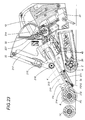
- the different way of tilting the covering structure 31 makes it possible to change the arrangement of the edge band 4 feed means 11 (along a 90° arc, which is a more compact arrangement than the one described above) but not the way they are made within the covering structure (as can be seen in Figures 22, 23, and 24).
- the carriage 210 has a fixed base 211 and a pair of arms 212 and 213 located opposite the base 211 in such a way as to form the continuation of the channel 12 for the passage of the edge band. Acting on the carriage 210 there is a cylinder 214 connected to the covering structure 31 and designed to drive the carriage 210 from a retracted, idle position (see Figure 22) to a forward, working position in which it carries the edge band 4 close to the edge 1b (see Figure 23). The edge band 4 is carried at the same speed as that at which the rollers 32 feed it in direction D.
- the stem of the cylinder 214 is connected to the end of the arm 212, which is L-shaped and pivoted at F212 to the body of the carriage 210 in such a way as to allow a portion of the edge band 4 to be rotated to a stop position in direction FC during the passage from the retracted to the forward position, under the thrusting action of the cylinder 214, and then to rotate the edge band 4 to a released position in the opposite direction FS when it is applied to the edge 1b.
- the release is effected by further moving forward only the carriage 210, with the stem fixed and acting this time as a centre of rotation.
- the carriage 210 returns to the retracted, idle position and stays there until the end of the working cycle on the current panel.
- the edge band feed means 11 further comprise a feed arm 215 that applies glue to the edge band 4, this arm being equipped with a counter roller 216 at its free end and a cylinder 217 that drives it from an idle position, in which it is away from the glue applicator roller 6 and a working position (indicated by the arrow F215 in Figure 24), in which it is close to the glue applicator roller 6, with the edge band 4 (not illustrated in this case) between the roller 6 and the counter roller 216.
- a feed arm 215 that applies glue to the edge band 4
- this arm being equipped with a counter roller 216 at its free end and a cylinder 217 that drives it from an idle position, in which it is away from the glue applicator roller 6 and a working position (indicated by the arrow F215 in Figure 24), in which it is close to the glue applicator roller 6, with the edge band 4 (not illustrated in this case) between the roller 6 and the counter roller 216.
- the loading of the edge band 4 may be effected again independently of the direction of rotation of the glue applicator roller 6 because the two rollers 32 that feed and load the edge band 4 have corresponding kinematic elements 218 which enable them to also rotate in the feed direction D in such a way as to feed the edge band but independently of the direction of rotation of the glue applicator roller 6.
- the kinematic elements 218 consist of a pair of first toothed wheels 218a and 218b (drawn with dashed lines in Figure 21) keyed to a single rotating shaft 219 connected to the feed rollers 32 through a unit that transmits motion to all the means for feeding the edge band and the glue (not illustrated in this case).
- the two first toothed wheels 218a and 218b are housed at the top of the covering structure 31 and each of the two first toothed wheels 218a and 218b meshes with corresponding second toothed wheels 220 and 221 which are linked to the drive elements 222 of the device, are connected to the (motor-driven) shaft forming the main axis Z, and are driven in opposite directions of rotation.
- the kinematic elements 222 comprise a drive wheel 222a on the shaft forming the main axis Z and meshed with a driven wheel 222b which enable drive to be transmitted to the two above mentioned second toothed wheels 220 and 221: one of the second toothed wheels, the one labelled 220, meshes directly with one of the first toothed wheels, the one labelled 218a, while the other second toothed wheel, the one labelled 221, meshes with an idle wheel 221a which meshes with the first wheel 218b.
- Each of the first toothed wheels 218a and 218b is equipped with free wheel means 218c designed to enable it to turn freely on the shaft 219 when the shaft forming the main axis Z turns in the direction opposite to its own.
- the covering structure 31 also comprises means 223 for detecting the length of the edge band 4 and cutting off the edge band 4 when it has gone right around the panel to join the starting end 4a that was applied first.
- the detecting means 223 consist of a rod 224, which is pivoted at F224 to the covering structure 31 and which can rotate between an idle position (see Figure 25) in which it is withdrawn inside the covering structure 31, and a working position (accomplished by conventional drive means which are not illustrated), in which it protrudes from the structure (see arrow F224a in Figures 24 and 26) when necessary and is positioned close to the edge 1b, with a part in contact with the lower surface of the panel 1 to be edge banded.
- the rod 224 is equipped with presence sensors 225 and 226 located opposite each other and designed to detect the starting end 4a of the edge band 4 (protruding from the edge 1b and thus blacking out the two sensors) and to send a signal to the control unit 50 which processes the signal and activates a cutoff unit 227, preferably located between the edge band 4 loading rollers 32 and the carriage 210, which cuts the edge band in a direction indicated by the arrow F227 in Figure 22 and thanks to a front stop 227s located on the channel 12.
- the calculation for cutting the edge band 4 at the correct point is made on the basis of preset parameters programmed in the control unit 50.
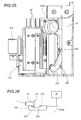
- the cutoff unit 227 (see Figure 28) consists of a circular cutter 228 mounted on a base 229 that is slidably connected to the covering structure 31 and linked to a cylinder 230 that drives it between a forward working position and a retracted, idle position (see arrow F228 in Figure 28).
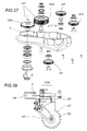
- Figure 29 shows the lower part of the glue feed means 7, that is, the part that controls the pair of glue spreader rollers 30 (not illustrated in Figure 29).
- the two glue spreader rollers 30 are equipped with independent drive means 231 which open and close them in accordance with the direction of rotation of the glue applicator roller 6 and even according to where the glue is to be applied (on the panel edge 1b or on the edge band 4).
- the drive means 231 consist of a vertical shaft 232 and 233 to connect each cylinder 30, each shaft 232, 233 being equipped with a rod 234, perpendicular to it and acted upon by cam means 235 which are in turn acted upon by drive means 236 in such a way as to open one spreader roller 30 and close the other and vice versa (in the illustration, the shaft 232 has opened its spreader roller - see arrow F232 - while the shaft 233 is keeping its cylinder 30 in the closed position).
- cam means 235 consist of a tubular carriage 238 within which the shafts 232, 233 can be housed, each shaft having a cam follower pin 239 placed in contact with the corresponding cam profiles 240 made on a wall of the carriage 238: this way, when the drive means 236 (consisting of a two-position pneumatic cylinder connected to the carriage 238) are moved in one direction or the other, one or other of the spreader rollers 30 is opened (see arrow F236 in Figure 29).
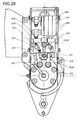
- Figures 30 to 33 show the part of the device comprising the first and second pressure rollers 8 and 14 which press the edge band 4 on the panel 1.
- the first pressure roller 8 can slide along the central supporting arm 18 so that its axis of rotation moves away from the main axis Z (see arrow FZ in Figure 31): this mechanism prevents the first roller 8 from jamming on the edge 1b of the panel 1 when it meets particularly sharp corners (for example at right angles) where the thrust applied by the first pressure means 10 to the roller 8 would risk breaking the roller if it were not free to slide.
- the first roller 8 slides on a first guide 241 and, at the top of it, has a cam profile 242 that acts on a cam follower roller 243 connected to an element 244 used to regulate the pressure exerted by the first pressure means 10 so as to adjust the position of the first roller 8.
- the regulator 244 is designed to reduce the pressure of the roller 8 on the edge 1b (see arrow F244 in Figure 30) by releasing pressure from one chamber to the other of the cylinder forming the first drive means 22, as the roller moves away from the main axis Z on account of the force tending to jam it and created by the cam follower roller 243 moving back (see arrow F243).
- Means 245 are envisaged to act on the first pressure means 10 so as to restore initial working conditions when the jamming force stops. These means may be constituted by the control unit 50 or by another cylinder 244c mounted in parallel with the cylinder 22 and always set to thrust conditions in parallel with the cylinder 22.
- first pressure roller 8 also applies to the second pressure roller 14, which slides along the central arm 18 so that its axis of rotation moves away from the main axis Z (see arrow F246 in Figures 32 and 33).
- the second roller 14 slides on a second guide 246 made on the central arm 18 and, at the top of it, the roller has a cam profile 247 that in turn acts on a cam follower roller 248 connected to regulator valve means 249 used to reduce the pressure exerted by the second pressure means 17 (that is, of the cylinder 27) acting on the second roller 14 in such a way as to reduce its pressure on the edge 1b.
- the device as described above therefore achieves the aims of the invention by providing an extremely compact unit equipped with a reference roller which may be used either to apply glue to the panel edge or simply as a contact roller used to reference the panel.
- a reference roller which may be used either to apply glue to the panel edge or simply as a contact roller used to reference the panel.
Abstract
Description
- The present invention relates to a device for applying edge banding to panels, especially panels of various different shapes, made of wood, plastic or similar materials and used preferably to make items of furniture.
- At present, the operation by which edge banding, usually a strip of synthetic material, is glued to the edges of panels with curved profiles is carried out using equipment of various kinds, based on the different constructional principles followed by different manufacturers of woodworking machinery.
- This equipment consists basically of a work table on which the panel to be edged is placed and means for applying the edging. The work table and the means for applying the edging move relative to each other so that the edging can be glued right round the perimeter of the panel.
- By way of example, one solution for a piece of equipment of this kind is disclosed in German patent application DE - OS 35.17.194 in which the work table, with the panel on it, can rotate about a vertical axis, while the edge banding application means, comprising a roller that presses on the edge band while the latter is being fed, are driven only along the longitudinal axis of the machine in such a way as to copy the profile of the panel as it comes into contact with the pressure roller.
- A more recent solution is disclosed in patent publications EP 276.358 and EP 510.231 which describe an apparatus that has a fixed table, to which the panel is secured, and a carriage equipped with an arm that mounts the devices for feeding the edge band, applying the edge band, machining the edge and cutting off the edge band. The carriage moves along two controlled axes X and Y above and in parallel with the surface of the panel to apply the edge band to the panel and finish the edge.
- These solutions envisage the use of pre-glued edge banding which, just before being applied to the panel, is heated in such a way as to reactivate the glue. The disadvantage of this method is that, since the amount of glue forming the layer of pre-applied glue must be limited, it is not always enough to "cover" the pores in the edge of the panel. In short, machines of this kind sometimes work with "less than sufficient glue".
- There are also "through" machines, that is to say, linear edge banding machines designed to apply edge bands to panels with straight edges and in which the panel is fed relative to the edge banding device, which remains fixed: with these machines, the glue may be applied either to the panel or to the edge band.
- The aim of the present invention is to overcome the disadvantages mentioned above by providing a panel edge banding device that is extremely easy to use, compact, adaptable to panels of any shape, quick to install and capable of securely joining the panel edge to the edge band with glue.
- The technical characteristics of the invention according to the above mentioned aims are described in the claims below and the advantages of the invention will become more apparent from the detailed description which follows, with reference to the accompanying drawings, which illustrate preferred embodiments of the invention and in which:
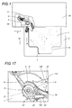
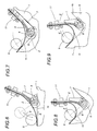
- Figure 1 shows a panel machine equipped with the edge banding device made according to the present invention, in a schematic top plan view with some parts cut away in order to better illustrate others;
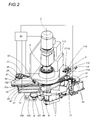
- Figure 2 shows the panel edge banding device made according to the present invention in a perspective view, scaled-up compared to Figure 1 and with some parts cut away in order to better illustrate others;
- Figure 3 is a top plan view, with some parts cut away in order to better illustrate others, of the panel edge banding device as shown in Figure 2;
- Figure 4 is a top plan view, with some parts cut away and others in cross section, of some of the working parts of the device shown in the illustrations listed above;
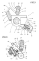
- Figure 5 is a schematic top plan view, with some parts cut away in order to better illustrate others, of some of the drive parts of the device disclosed herein;
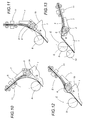
- Figures 6 to 9 are schematic top plan views of a series of working configurations that can be obtained with the device disclosed on a panel with a straight and concave profile;
- Figures 10 to 13 are schematic top plan views of a series of working configurations that can be obtained with the device disclosed on a panel with an angled profile;
- Figure 14 is a scaled-up detail of Figure 3, viewed from "J", showing a unit consisting of two pressure rollers in a side view with some parts in cross section and others cut away;
- Figures 15 and 16 are perspective views from below and above, respectively, and with some parts cut away in order to better illustrate others, of the twin-roller unit illustrated in Figure 14, equipped with means for adjusting the position of the rollers;
- Figure 17 is a schematic top plan view, with some parts cut away in order to better illustrate others, of another embodiment of the working parts illustrated in Figure 5;
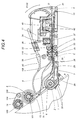
- Figure 18 shows the device made according to the present invention in a perspective view from K in Figure 3;
- Figure 19 is a side view, with some parts cut away in order to better illustrate others, of the device illustrated in Figure 18;
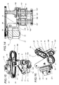
- Figure 20 is a perspective, exploded view of a part of the device disclosed showing the means for suspending a glue unit and an edge banding feed unit;
- Figure 21 is a longitudinal section of the area where the glue unit and the edge band feed unit are suspended, also showing some parts in perspective and partly cut away in order to better illustrate others;
- Figures 22 and 23 are top plan views, with some parts in cross section, of another embodiment of the edge band feed unit in two different working configurations;
- Figure 24 is a top plan view, with some parts in cross section, of yet another embodiment of the edge band feed unit shown in Figures 22 and 23;
- Figure 25 illustrates a part of the glue and edge band feed unit in a perspective view with some parts cut away in order to better illustrate others;
- Figure 26 illustrates a detail of Figure 25 in a schematic side view;
- Figure 27 is a perspective, exploded view of a plate that forms part of an upper cover of the glue and edge band feed unit, showing also some parts of the drive gear with reference to Figure 21;
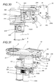
- Figure 28 is a side view, with some parts in cross section, of an end trimming tool that can be applied to the edge banding device disclosed;
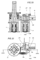
- Figure 29 is a top plan view, with some parts cut away in order to better illustrate others, of a feed cylinder drive unit;
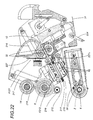
- Figures 30 and 31 show the pair of pressure rollers in a front view and a perspective view, respectively, and with some parts cut away in order to better illustrate others;
- Figure 32 is a top plan view of a part of the pair of pressure rollers shown in Figures 30 and 31;
- Figure 33 is a cross section through line XXIII-XXIII in Figure 32.
- With reference to the accompanying drawings, described above, in particular, Figure 1, the device disclosed herein applies edge banding to
panels 1 made of wood or other wood-based material, plastic or similar material and used preferably to make items of furniture. - As shown in Figure 1, the edges of the
panels 1 may have differently shaped profiles, for example, convex, angled or concave, and the edge banding should preferably but not necessarily be applied uninterruptedly right around thepanel 1. - The
panels 1 can be processed in machines whose basic structure consists of at least one work table 2 on which thepanel 1 is securely held, and application means 3 for gluing anedging band 4 to anedge 1b of thepanel 1 in a defined direction B. - The application means 3 and the work table 2 can move relative to each other and, in Figure 1, by way of example, they move along defined axes, the application means 3 along an axis X on a
crossbar 48 equipped with arail 49 on which the application means 3 run in both directions, while the work table 2 runs along an axis Y perpendicular to the axis X (in the case illustrated, the feed direction B is opposite to the feed direction B1 of the table 2 with thepanel 1 on it). - Obviously, this machine is illustrated by way of example only and the device can be applied to other types of machines without departing from the scope of the inventive concept.
- The application means 3 (see also Figures 2 and 3) consist of a unit with a motor-driven,
tubular shaft 5, that forms a vertical main axis Z and that mounts and, through motors and appropriate drive gear (not illustrated) located inside theshaft 5, drives the following items: acontact roller 6, which, as explained in more detail below, may also be used to apply glue to theedge 1b of thepanel 1, saidroller 6 rotating about its vertical axis, which coincides with the main axis Z; a firstmain pressure roller 8 of theedge band 4 and glue feed means 7. The last two items are positioned on opposite sides of theroller 6 and can oscillate about the main axis Z in accordance with the profile of thepanel 1. - The oscillation of the
main roller 8 and of the glue feed means 7 may be performed in two different ways. In one (the first embodiment described below), both the elements are able to tilt and the glue feed means 7 are also able to move in such a way as to follow the profile of thepanel 1. - With reference in particular to Figure 4, in a first embodiment in which the
roller 6 is also used to apply glue to theedge 1b, the surface of theroller 6 is in contact with the glue feed means 7, the glue feed means 7 consisting basically of aglue pot 28 in ahousing 29 made in the unit and located near theapplicator roller 6. Theglue pot 28 is equipped with a pair ofspreader rollers 30 which turn freely about the corresponding vertical axes and are located between theglue pot 28 and theglue applicator roller 6 so that they can uniformly spread glue on the outer surface of theroller 6 which in turn applies it to theedge 1b of thepanel 1. - In a second embodiment, illustrated schematically in Figure 17, in which the
roller 6 is simply a contact roller for theedge 1b, there are glue feed means 100, again consisting of a glue pot 28' and a pair of spreader rollers 30' in contact with another roller 6' which applies glue to the surface of theedge band 4 in direction D. The roller 6' is located downstream of thecontact roller 6 relative to the feed direction D of theedge band 4, whose other surface is guided by aguide element 40. - The guide element 40 (see Figure 17 again) consists of a
blade 109 mounted on arod 110 which is connected with a supportingstructure 31 and which slides axially between an idle position, in which theblade 109 is away from the glue applicator roller 6' and a working position (shown in Figure 17) in which theblade 109 is close to the roller 6' and opposes theedge band 4. As described in more detail below, theguide element 40 can be used as such even in the embodiment where theroller 6 is also used to apply glue to theedge 1b. - For convenience, we will now describe the embodiment where the
roller 6 is used to apply glue to theedge 1b of thepanel 1, although the structure of the unit described below is identical in both the embodiments mentioned above. - The first
main pressure roller 8 of theedge band 4 is located downstream of theapplicator roller 6 relative to the edge banding direction B, can turn freely about its vertical axis and is linked to a first connecting-rod 9 which is in turn pivoted to the shaft forming the main axis Z (see Figure 5 in particular). - The first connecting-
rod 9 is connected to first means 10 for pressing thefirst roller 8 against theedge 1b and at the same time adjusting the angular position of the roller relative to the position of theglue applicator roller 6 in accordance with the profile of theedge 1b of thepanel 1. In this way, themeans 10 keep thefirst roller 8 pressed against theedge band 4 that has just been laid on theedge 1b. - Looking in more detail and with reference also to Figures 2, 3 and 5, the first pressure and adjusting means of the first
main roller 8 consist of the first connecting-rod 9 pivoted to the shaft forming the main axis Z. - On the ends of the first connecting-
rod 9, there is a pair oftoothed wheels first chain 21 is looped. At onebranch 21a of thechain 21, there are first drive means 22, connected to the first connecting-rod 9 and acting on the first branch in such a way as to allow the connecting-rod to turn in both directions (see arrows F in Figure 5) according to the profile of theedge 1b. In other words, the first drive means 22, consisting for example, of a linear actuator, are extended and retracted (see arrow F1 in Figure 5) in such a way as to cause the first connecting-rod 9 to turn since thetoothed wheel 19 is keyed to themain shaft 5, that forms the main axis Z. - The
main pressure roller 8 is connected to the first connecting-rod 9 by acentral arm 18 which is attached at one end to the connecting-rod itself (or to a firstupper guard 150 where thelinear actuator 22 is also connected), which extends crossways with respect to thechain 21, and which, at its other end, mounts themain roller 8. The latter is therefore outside the working area of the first connecting-rod 9. - As shown in Figures 2 to 5, besides the first
main roller 8, there is at least onesecondary pressure roller 14 located downstream of the firstmain roller 8 relative to the edge banding direction B. - The
second roller 14 is linked to a second connecting-rod 15 pivoted at one end to afirst shaft 16, mounted on thefirst arm 18, which is coaxial with the firstmain roller 8 and which forms a pivot point G of thesecond roller 14. - There are also
second means 17 for pressing on thesecond roller 14 and adjusting its position relative to thefirst roller 8 in accordance with the profile of theedge 1b of thepanel 1, so that it remains in contact with theedge band 4 that has been applied. - Looking in more detail, the second pressing and adjustment means 17 consist of the second connecting-
rod 15 having, on the ends of it, corresponding secondtoothed wheels second chain 26 is looped, the secondtoothed wheel 24 being securely keyed to thefirst shaft 16. - At the other
toothed wheel 25, there are second means 27 for driving the second connecting-rod 15, themeans 27 consisting, for example, of a rotary actuator acting on thetoothed wheel 25 to turn thesecond roller 14 in both directions (see arrow F2 in Figure 5), relative to the position of thefirst roller 8, in accordance with the profile of theedge 1b and in such a way as to keep thesecond roller 14 in contact with the edge. - In short, structuring the two pressure rollers in this way provides two elements (both exerting pressure on the edge band but to different extents, the first roller more than the second) which are connected to each other in sequence and which are both able to rotate, the first about the pivot point Z and the second about the pivot point G, where the point G is the instantaneous position assumed by the
first roller 8. - As also shown in Figures 14, 15 and 16, the first and
second pressure rollers 8 and 14 (which are preferably made of steel) are mounted in such a way that they can turn freely on corresponding first andsecond shafts first shaft 101 is mounted at the free end of thecentral arm 18, while thesecond shaft 105 is mounted directly on the second connecting-rod 15. - On the ends of each of the two
shafts single element 104, at the lower end, that supports each of the two units consisting of theshaft roller rings - In practice, the first and
second shafts element 104 that has, in turn, a vertical joiningcolumn 108 connected to the second connecting-rod 15. - The two pairs of
rings corresponding rollers related shafts corresponding rollers band 4 applied to theedge 1b. - Thanks to this flexibility, the two rollers easily adapt to the shape of the surface being pressed, compensating for imperfect assembling of the rollers or irregularities on the
edge 1b of thepanel 1 caused by previous machining. That means that each of therollers edge band 4 and, hence, allows good product quality to be achieved. - The numeral 11 in Figure 4 indicates means for feeding the
edge band 4. The means 11 are located close to theroller 6 that applies glue to theedge 1b and move together with the glue feed means 7. - The means 11 are made in such a way as to form a
channel 12 through which theedge band 4, when required, is fed to theedge 1b in anarea 13 between theapplicator roller 6 and the twopressure rollers edge band 4 is placed in contact with the surface of theedge 1b and pressed by therollers - Looking in more detail, the feed means 11 comprise a supporting and covering
structure 31 which houses a first pair of motor-drivenrollers 32 for feeding the edge band 4 (which comes from a magazine that is not illustrated), the rollers being fitted opposite each other in such a way as to move the continuous edge band towards theedge 1b in the feed direction D. - Downstream of the pair of
rollers 32, relative to the feed direction D, there are means 33 for detecting the passage of theedge band 4, operating on related stop means 34 located upstream of the pair ofrollers 32, again relative to the feed direction D. The means 34 are designed to stop the feeding of theedge band 4 according to the position of the unit relative to theedge 1b. - The
edge band 4 detectingmeans 33 may consist (see Figure 4 again) of at least one pair ofoptical units 35 placed opposite each other. The stop means 34 may consist of: apresser element 36 which, when activated, acts in a direction transversal to the feed direction D on a section of theedge band 4 being fed; and astraight wall 37 against which thepresser element 36 presses theedge band 4 to stop it. - In addition to these elements, the supporting
structure 31 also houses anarm 38 designed to guide theedge band 4 and located downstream of the detecting means 33 relative to the feed direction D. Theguide arm 38 is positioned parallel to theedge band 4 and is pivoted at one end, at C, to the supportingstructure 31. - The
arm 38 has drive means 39 (which may consist of a cylinder, illustrated schematically as a block in Figure 4), themeans 39 allowing the arm to rotate between two or, preferably, three positions: an idle position (shown by a continuous line in Figure 4) when noedge band 4 is detected and in which thearm 38 is close to theglue pot 28, and at least two working feed positions (of which one is clearly visible in Figures 6 to 13 and shown by dashed lines in Figure 4) in which thearm 38 is away from theglue pot 28, close to theguide element 40 and in contact with theedge band 4 in such a way as to keep the latter on a defined feed line which does not interfere with theglue applicator roller 6 limits the risk of the edge band springing back against theglue applicator roller 6. Obviously, the working angle of thearm 38 depends on the thickness of theedge band 4. - The numeral 41 indicates means for heating the
edge band 4 located upstream of the stop means 34, relative to the feed direction D, and designed to make the edge band more pliable, especially when the edge banding being applied is quite thick. - The heating means 41 comprise one or more short-wave infrared
ray emitting units 42 positioned parallel to each other and transversal to the direction of feed D. - As mentioned above, the feed means 11 just described and the glue feed means 7 can tilt about the shaft that forms the main axis Z.
- This angular adjustment is accomplished by means 110 (visible clearly in Figures 18 and 19) and partly in Figures 2 and 3) for adjusting the position of the
means panel 1. - The adjustment means 110 consist of the above mentioned supporting and covering
structure 31 of all the parts just described that form themeans 11 for feeding theedge band 4 and themeans 7 for feeding the glue, thestructure 31 being free to turn about the main axis Z. - At the top of the supporting
structure 31, there is alinear guide 111, that is slidably coupled to a counter-guide 112 made on a main mountingplate 113 that is rotatably connected to theshaft 5 forming the main axis Z. - The
main mounting plate 113 comprisesmeans 114 that drive it and, hence, also drive the supportingstructure 31. The means 114 enable theplate 113 and the supportingstructure 31 to tilt about the main axis Z in both directions (see arrow F110 in Figures 2, 3 and 18) thanks to the relative sliding of theguide 11 and the counter-guide 112. - The means 114 may consist of a
cylinder 115 connected with the mountingplate 113 and whosestem 115s is connected to a fixedwall 116 in such a way that the stem can extend and retract in order to tilt the mountingplate 113 and the supportingstructure 31 in accordance with the profile of theedge 1b of thepanel 1. - Looking again at the above mentioned
central arm 18, forming part of the first connecting-rod 9 and mounting thefirst roller 8, thearm 18 is equipped withmeans 43 that lock it in a fixed position in which the firstmain roller 8 is away from theedge 1b of thepanel 1 when theglue applicator roller 6 comes into contact with the panel edge (see Figures 2, 15 and 16): this configuration is used, preferably during the initial stages of the edge banding operation to prevent the glue on thepanel edge 1b from being smeared on the surface of theroller 8 and subsequently soiling the outer surface of theedge band 4. - The locking means 43 comprise a
vertical pin 44 connected with thearm 18 and which can move along its vertical axis between a lowered, idle position in which thearm 18 is able to move, allowing the firstmain roller 8 to come into contact with theedge 1b, and a raised, working position (shown in Figure 2), in which thepin 44 is in contact with awall 45 attached to a fixedstructure 46 of the device (forming part of the shaft 5) in such a way as to determine said fixed position. - The fixed
wall 45 has a setscrew 47 that can be placed opposite thepin 44 in order to vary the position in which thearm 18 stops relative to the set screw so as to adjust the distance between thefirst roller 8 and theedge 1b in the fixed position. - All the working parts described up to now are controlled and driven by a
control unit 50, illustrated schematically as a block in Figure 2. - This unit may be a conventional, CNC system programmed according to the profile of the panel to be edge banded and acting on the device and on the work table 2.
- As can be deduced from the above description, the edge banding device operates basically as follows starting from the configuration illustrated in Figure 4, that is to say, with the
edge band 4 stopped inside thechannel 12 by the locking means 34 and thearm 18 locked in the fixed position by the raising of thepin 44. - The unit is moved close to the
edge 1b of thepanel 1 until theedge 1b and theglue applicator roller 6 touch, while themeans 50 adjust the position of the mountingplate 113 and thestructure 31, acting also on thepiston 115, in such a way as to put it in the position most suitable to apply the glue and feed theedge band 4 without interfering with theedge 1b. The unit starts moving in the application direction B, while theedge band 4 is fed towards theoutfeed area 13 by therollers 32. When theedge band 4 comes into contact with theedge 1b, thearm 18 is released by the lowering of thepin 44 and can start pressing on theedge band 4, together with thesecond roller 14, in order to join it to theedge 1b (see Figure 6). - This working configuration continues until the
edge 1b right around the panel is covered, the unit even assuming "limit" positions as it follows the profile of the edge: Figures 7 to 9, for example, show the unit as it works on an edge with a profile that forms a right-angled concavity, and highlight the extreme flexibility of the components, especially the tilting (indicated by the arrows E) of the pressure rollers and of the glue andedge band 4 feed unit which allows them to automatically move to the most suitable working position according to the edge profile and without slowing down their operation. - Figures 10 to 13 show another working "limit" condition in which the unit disclosed can apply the edge band quickly and reliably, with top-quality results, thanks also to the double joint of the pressure rollers, shown clearly in Figure 13.
- Without changing the structure of the components described until now, and as mentioned at the beginning of the present description, the glue feed means 7, incorporated in the edge band feed means 11, may be connected to the shaft which forms the main axis Z through
suspension elements 200 designed to enable them to oscillate in a straight line with an irrotational movement in a plane and along two axes perpendicular to the main axis Z. - Looking in more detail (see Figures 20 and 21), the
suspension elements 200 are located between the main mountingplate 113, connected to the fixed structure of the device, and the coveringstructure 31 that houses the feed means 7 and the edge band feed means 11 (in these illustrations, themeans plate 113/coveringstructure 31 assembly. - The
suspension elements 200 consist of three separate pairs of connecting-rods plate 113 and the coveringstructure 31 and linked to them at corresponding limit points. The three pairs of connecting-rods are also connected to each other at corresponding intermediate points by a rigid, substantially Y-shaped element 204: thanks to this configuration, the entire underlying unit can be moved in a plane instead of tilted as described above. - This particular movement requires means of controlling the position of the covering
structure 31 relative to the profile of theedge 1b to be edge banded, that is to say, between the main mountingplate 113 and the coveringstructure 31, there may be means for controlling the position of the coveringstructure 31 relative to the main axis Z. - Said position control means may comprise a pair of
cylinders 205 and 206 (the latter is only partly visible in Figure 21) fitted at right angles to each other and linked to the coveringstructure 31, at one end, while the relative stem is connected to a singlevertical reference pin 207 connected to the coveringstructure 31. Thevertical pin 207 is lined up with anopening 208 made in the main mountingplate 113 and on the other side of which there is an inductive sensor 209 (drawn with a dashed line), housed in the mountingplate 113. The sensor is designed to detect the presence of thepin 207 at theopening 208 and to stop the entire device if thepin 207 moves away from theopening 208. The moving away of the pin from the opening indicates that the coveringstructure 31 is in the wrong position relative to theedge 1b and leads to a program fault in thecontrol unit 50. - The different way of tilting the covering
structure 31 makes it possible to change the arrangement of theedge band 4 feed means 11 (along a 90° arc, which is a more compact arrangement than the one described above) but not the way they are made within the covering structure (as can be seen in Figures 22, 23, and 24). - An addition to the elements described above is illustrated in Figures 22 and 23, where a
carriage 210 has been added to guide and carry theedge band 4 from the pair offeed rollers 32 to the proximity of theedge 1b at the start of the work cycle, that is, when the edge band starts being applied to thepanel 1. - The
carriage 210 has a fixedbase 211 and a pair ofarms channel 12 for the passage of the edge band. Acting on thecarriage 210 there is acylinder 214 connected to the coveringstructure 31 and designed to drive thecarriage 210 from a retracted, idle position (see Figure 22) to a forward, working position in which it carries theedge band 4 close to theedge 1b (see Figure 23). Theedge band 4 is carried at the same speed as that at which therollers 32 feed it in direction D. - The stem of the
cylinder 214 is connected to the end of thearm 212, which is L-shaped and pivoted at F212 to the body of thecarriage 210 in such a way as to allow a portion of theedge band 4 to be rotated to a stop position in direction FC during the passage from the retracted to the forward position, under the thrusting action of thecylinder 214, and then to rotate theedge band 4 to a released position in the opposite direction FS when it is applied to theedge 1b. The release is effected by further moving forward only thecarriage 210, with the stem fixed and acting this time as a centre of rotation. - Once the
edge band 4 has been loaded, thecarriage 210 returns to the retracted, idle position and stays there until the end of the working cycle on the current panel. - In another embodiment, illustrated in Figure 24, the edge band feed means 11 further comprise a
feed arm 215 that applies glue to theedge band 4, this arm being equipped with acounter roller 216 at its free end and acylinder 217 that drives it from an idle position, in which it is away from theglue applicator roller 6 and a working position (indicated by the arrow F215 in Figure 24), in which it is close to theglue applicator roller 6, with the edge band 4 (not illustrated in this case) between theroller 6 and thecounter roller 216. - The loading of the
edge band 4 may be effected again independently of the direction of rotation of theglue applicator roller 6 because the tworollers 32 that feed and load theedge band 4 have correspondingkinematic elements 218 which enable them to also rotate in the feed direction D in such a way as to feed the edge band but independently of the direction of rotation of theglue applicator roller 6. - The kinematic elements 218 (see Figures 21 and 27) consist of a pair of first
toothed wheels rotating shaft 219 connected to thefeed rollers 32 through a unit that transmits motion to all the means for feeding the edge band and the glue (not illustrated in this case). The two firsttoothed wheels structure 31 and each of the two firsttoothed wheels toothed wheels drive elements 222 of the device, are connected to the (motor-driven) shaft forming the main axis Z, and are driven in opposite directions of rotation. - In practice, the
kinematic elements 222 comprise adrive wheel 222a on the shaft forming the main axis Z and meshed with a drivenwheel 222b which enable drive to be transmitted to the two above mentioned secondtoothed wheels 220 and 221: one of the second toothed wheels, the one labelled 220, meshes directly with one of the first toothed wheels, the one labelled 218a, while the other second toothed wheel, the one labelled 221, meshes with anidle wheel 221a which meshes with thefirst wheel 218b. - Each of the first
toothed wheels shaft 219 when the shaft forming the main axis Z turns in the direction opposite to its own. - The covering
structure 31 also comprisesmeans 223 for detecting the length of theedge band 4 and cutting off theedge band 4 when it has gone right around the panel to join the startingend 4a that was applied first. - As shown in Figures 24, 25 and 26, the detecting means 223 consist of a
rod 224, which is pivoted at F224 to the coveringstructure 31 and which can rotate between an idle position (see Figure 25) in which it is withdrawn inside the coveringstructure 31, and a working position (accomplished by conventional drive means which are not illustrated), in which it protrudes from the structure (see arrow F224a in Figures 24 and 26) when necessary and is positioned close to theedge 1b, with a part in contact with the lower surface of thepanel 1 to be edge banded. - The
rod 224 is equipped withpresence sensors end 4a of the edge band 4 (protruding from theedge 1b and thus blacking out the two sensors) and to send a signal to thecontrol unit 50 which processes the signal and activates acutoff unit 227, preferably located between theedge band 4loading rollers 32 and thecarriage 210, which cuts the edge band in a direction indicated by the arrow F227 in Figure 22 and thanks to afront stop 227s located on thechannel 12. - The calculation for cutting the
edge band 4 at the correct point is made on the basis of preset parameters programmed in thecontrol unit 50. - The cutoff unit 227 (see Figure 28) consists of a
circular cutter 228 mounted on a base 229 that is slidably connected to the coveringstructure 31 and linked to acylinder 230 that drives it between a forward working position and a retracted, idle position (see arrow F228 in Figure 28). - Figure 29 shows the lower part of the glue feed means 7, that is, the part that controls the pair of glue spreader rollers 30 (not illustrated in Figure 29).
- The two
glue spreader rollers 30 are equipped with independent drive means 231 which open and close them in accordance with the direction of rotation of theglue applicator roller 6 and even according to where the glue is to be applied (on thepanel edge 1b or on the edge band 4). - The drive means 231 consist of a
vertical shaft cylinder 30, eachshaft rod 234, perpendicular to it and acted upon by cam means 235 which are in turn acted upon by drive means 236 in such a way as to open onespreader roller 30 and close the other and vice versa (in the illustration, theshaft 232 has opened its spreader roller - see arrow F232 - while theshaft 233 is keeping itscylinder 30 in the closed position). - Between the two
rods 234, there are spring means 237 designed to keep the rods apart so as to keep thecorresponding spreader rollers 30 closed when the spreader rollers themselves and thedrive cylinder 236 are in the idle position. - Looking in more detail, the above mentioned cam means 235 consist of a
tubular carriage 238 within which theshafts cam follower pin 239 placed in contact with the corresponding cam profiles 240 made on a wall of the carriage 238: this way, when the drive means 236 (consisting of a two-position pneumatic cylinder connected to the carriage 238) are moved in one direction or the other, one or other of thespreader rollers 30 is opened (see arrow F236 in Figure 29). - Figures 30 to 33 show the part of the device comprising the first and
second pressure rollers edge band 4 on thepanel 1. - From these illustrations it can be seen that the
first pressure roller 8 can slide along the central supportingarm 18 so that its axis of rotation moves away from the main axis Z (see arrow FZ in Figure 31): this mechanism prevents thefirst roller 8 from jamming on theedge 1b of thepanel 1 when it meets particularly sharp corners (for example at right angles) where the thrust applied by the first pressure means 10 to theroller 8 would risk breaking the roller if it were not free to slide. - The
first roller 8 slides on afirst guide 241 and, at the top of it, has acam profile 242 that acts on acam follower roller 243 connected to anelement 244 used to regulate the pressure exerted by the first pressure means 10 so as to adjust the position of thefirst roller 8. Theregulator 244 is designed to reduce the pressure of theroller 8 on theedge 1b (see arrow F244 in Figure 30) by releasing pressure from one chamber to the other of the cylinder forming the first drive means 22, as the roller moves away from the main axis Z on account of the force tending to jam it and created by thecam follower roller 243 moving back (see arrow F243). -
Means 245 are envisaged to act on the first pressure means 10 so as to restore initial working conditions when the jamming force stops. These means may be constituted by thecontrol unit 50 or by anothercylinder 244c mounted in parallel with thecylinder 22 and always set to thrust conditions in parallel with thecylinder 22. - The above description of the
first pressure roller 8 also applies to thesecond pressure roller 14, which slides along thecentral arm 18 so that its axis of rotation moves away from the main axis Z (see arrow F246 in Figures 32 and 33). - The
second roller 14 slides on asecond guide 246 made on thecentral arm 18 and, at the top of it, the roller has acam profile 247 that in turn acts on acam follower roller 248 connected to regulator valve means 249 used to reduce the pressure exerted by the second pressure means 17 (that is, of the cylinder 27) acting on thesecond roller 14 in such a way as to reduce its pressure on theedge 1b. - When the force tending to jam the
second roller 14 stops, the initial working conditions are restored by spring means 250 connected to the roller and to the central arm 18 (see arrow F250 in Figure 31). - The device as described above therefore achieves the aims of the invention by providing an extremely compact unit equipped with a reference roller which may be used either to apply glue to the panel edge or simply as a contact roller used to reference the panel. Working in conjunction with this roller, on each side of it, there are compact operating units which are flexibly positioned thanks to the possibility of oscillating either by tilting about the main reference axis or moving in a straight line and which are structured in such a way as to apply edge banding quickly and reliably, even to panels with profiles having extremely "difficult" shapes.
Claims (46)
- A device for applying edge banding to panels (1), especially panels which have differently shaped profiles and which can be worked on machines having at least one work table (2) on which the panel (1) is securely held, and application means (3) for gluing an edging band (4) to an edge (1b); the application means (3) and the work table (2) being able to move relative to each other, said device being characterized in that the means (3) for applying the edge band (4) consist of a unit with a motor-driven, shaft forming a vertical main axis (Z) and that mounts and drives at least the following items:a contact roller (6) for the edge (1b) of the panel (1), capable of rotating freely about its vertical axis, which coincides with the main axis (Z); means (7) for feeding glue and at least one first main pressure roller (8), which presses on the edge band (4), located on opposite sides of the roller (6) and able to oscillate about the main axis (Z) in accordance with the profile of the panel (1).
- The device according to claim 1, characterized in that the glue feed means (7) and the main roller (8) are connected to the shaft forming the main axis (Z) in such a way that they can tilt about the axis so as to follow the profile of the panel (1).
- The device according to claim 1, characterized in that the glue feed means (7) are connected to the shaft forming the main axis (Z) in such a way that they can move in a straight line and thus follow the profile of the panel (1).
- The device according to claim 3, characterized in that the glue feed means (7) are connected to the shaft which forms the main axis (Z) through suspension elements (200) designed to enable them to oscillate in a straight line with an irrotational movement in a plane and along two axes perpendicular to the main axis (Z).
- The device according to claims 1 to 4, characterized in that the roller (6) is a roller that applies glue to the edge (1b) and is connected to the glue feed means (7) which spread glue on the roller (6).
- The device according to claims 1 to 4, characterized in that the roller (6) is a contact roller for the edge (1b) and in that there are means (100) for applying glue directly to the edge band (4).
- The device according to claim 1, characterized in that the first main pressure roller (8) of the edge band (4) is located downstream of the contact roller (6), relative to the direction (B) in which the edge band (4) is applied, can turn freely about its vertical axis and is linked to a first connecting-rod (9) which is in turn pivoted at one end to the shaft forming the main axis (Z); the first connecting-rod (9) being connected to first means (10) for pressing the first roller (8) against the edge (1b) and at the same time adjusting the angular position of the roller relative to the position of the contact roller (6) in accordance with the profile of the edge (1b) of the panel (1) and in such a way as to keep the first roller (8) pressed against the edge band (4).
- The device according to claims 1 to 4, characterized in that it comprises means (11) for feeding the edge band (4) in the direction of the edge (1b) of the panel (1), located close to the contact roller (6) and able to oscillate, together with the glue feed means (7) about the main axis (Z) in accordance with the profile of the panel (1).
- The device according to claims 1 to 5, characterized in that it comprises means (11) for feeding the edge band (4) in the direction of the edge (1b) of the panel (1), located close to the glue applicator roller (6) and able to oscillate, together with the glue feed means (7) about the main axis (Z) in accordance with the profile of the panel (1); said edge band (4) feed means (11) being made in such a way as to form a channel (12) through which the edge band (4), when required, is fed to the edge (1b) in an area (13) between the glue applicator roller (6) and the first main pressure roller (8).
- The device according to claim 1, characterized in that it comprises a secondary pressure roller (14) located downstream of the first, main roller (8) relative to a direction (B) in which the edge band (4) is applied and linked to a second connecting-rod (15) pivoted at one end to a first shaft (16) connected to the first central arm (18) mounting the first main roller (8) and forming a pivot point (G) of the second roller (14); there being second pressure means acting on the second roller (14) and used to adjust its position relative to the first roller (8) in accordance with the profile of the panel (1) so that it remains in contact with the edge band (4).
- The device according to claim 7, characterized in that the means (10) for pressing and adjusting the position of the first roller (8) consist of the first connecting-rod (9) with a pair of toothed wheels (19, 20) at each end, of which one is securely keyed to the shaft that forms the main axis (Z); the toothed wheel (19, 20) having a first chain (21) looped around them; there being, at one branch (21a) of the chain (21), first drive means (22) connected to the first connecting-rod (9) and acting on the first branch in such a way as to allow the connecting-rod (9) to turn in both directions according to the profile of the edge (1b); said first connecting-rod (9) also having a central arm (18) extending transversally to the chain (21) and rotatably mounting at its free end the first main roller (8).
- The device according to claim 10, characterized in that the second pressure and adjustment means (17) consist of a second connecting-rod (15) having, on the ends of it, corresponding second toothed wheels (24, 25) around which a second chain (26) is looped; the second toothed wheel (24) being securely keyed to the first shaft (16) and, at the other toothed wheel (25), there being second means (27) for driving the second connecting-rod (15), acting on the second chain (26) and designed to turn the second roller (14) relative to the position of the first roller (8) in both directions, in accordance with the profile of the edge (1b) and in such a way as to keep the second roller (14) in contact with the edge.
- The device according to claims 1 to 5, characterized in that the glue feed means (7) consist of a glue pot (28) in a housing (29) made in the unit and located near the applicator roller (6); the glue pot (28) being equipped with a pair of spreader rollers (30) which turn freely about the corresponding vertical axes and located between the glue pot (28) and the glue applicator roller (6) so that they can uniformly spread glue on the outer surface of the roller (6).
- The device according to claims 8 and 9, characterized in that the means (11) for feeding the edge band (4) comprise, within a supporting and covering structure (31), at least one pair of motor-driven rollers (32) used for loading the edge band (4) and fitted opposite each other in such a way as to move the continuous edge band (4) towards the edge (1b) in a feed direction (D); there being means (33) for detecting the passage of the edge band (4), located downstream of the pair of rollers (32) relative to the feed direction (D) and operating on related stop means (34) located upstream of the pair of rollers (32) relative to the feed direction (D) and designed to stop the feeding of the edge band (4) according to the position of the unit.
- The device according to claim 14, characterized in that the means (33) for detecting the passage of the edge band (4) consist at least one pair of optical units (35) placed opposite each other.
- The device according to claim 14, characterized in that the stop means (34) consist of a presser element (36) acting on a section of the edge band (4) being fed and a straight wall (37) against which the presser element (36) presses the edge band (4) to stop it.
- The device according to claim 14, characterized in that the means (11) for feeding the edge band (4) comprise, downstream of the detecting means (33) relative to the feed direction (D), an arm (38) for guiding and spacing the edge band (4) from a glue applicator roller (6), positioned parallel to the edge band (4) and pivoted at one end, at (C), to the supporting structure (31); the arm (38) being equipped with drive means (39) designed to allow the arm to rotate at least between two limit positions, of which one is an idle position when no edge band (4) is detected and in which the arm (38) is away from a guide wall (40) of the edge band (4), and at least one working, feed position in which the arm (38) is close to the guide wall (40) and in contact with the edge band (4) being fed in such a way as to keep the latter on a defined feed line which does not interfere with the glue applicator roller (6).
- The device according to claim 14, characterized in that the edge band (4) feed means (11) comprise means (41) for heating the edge band (4) located upstream of the stop means (34), relative to the feed direction (D), and designed to make the edge band more pliable when required.
- The device according to claim 18, characterized in that the heating means (41) comprise one or more short-wave infrared ray emitting units (42) positioned parallel to each other and transversal to the direction of feed (D).
- The device according to claim 11, characterized in that the central arm (18) is equipped with means (43) that lock it in a fixed position in which the first main roller (8) is away from the edge (1b) of the panel (1) when a contact roller (6) comes into contact with the panel edge.
- The device according to claim 20, characterized in that the locking means (43) comprise a vertical pin (44) connected with the central arm (18) and which can move along its vertical axis between a lowered, idle position in which the central arm (18) is able to move, allowing the first main roller (8) to come into contact with the edge (1b), and a raised, working position in which the pin (44) is in contact with a wall (45) attached to a fixed structure (46) of the device in such a way as to determine said fixed position; the fixed wall (45) having a set screw (47) that can be placed opposite the pin (44) in order to vary the position in which the central arm (18) stops relative to the set screw so as to adjust the distance between the first roller (8) and the edge (1b) in the fixed position.
- The device according to claim 7, characterized in that the first main pressure roller (8) of the edge band (4) is mounted in such a way that it can turn freely on a first shaft (101) mounted at the free end of the central arm (18) of the first connecting-rod (9); there being, on the ends of the shaft (101), corresponding first rubber rings (102, 103) designed to provide the first shaft (101) and the first roller (8) with axial flexibility so that they can adjust to different shapes when they come into contact with the band (4) applied to the edge (1b).
- The device according to claim 10, characterized in that the second pressure roller (14) of the edge band (4) is mounted in such a way that it can turn freely on a second shaft (105) mounted on the second connecting-rod (15); there being, on the ends of the second shaft (105), corresponding second rubber rings (106, 107), said second rubber rings (106, 107) being designed to provide the second shaft (105) and the second roller (14) with axial flexibility so that they can adjust to different shapes when they come into contact with the band (4) applied to the edge (1b).
- The device according to claims 22 and 23, characterized in that the first and second shafts (101, 105) of the corresponding first and second rollers (8, 14) are rigidly connected to each other at their lower ends by a single supporting element (104) having a vertical column (108) connected to the second connecting-rod (15).
- The device according to claim 6, characterized in that it comprises a guide element (40), located close to the contact roller (6), said guide element (40) consisting of a blade (109) mounted on a rod (110) which slides axially between an idle position, in which the blade (109) is away from the contact roller (6) and a working position in which the blade (109) is close to the glue application means (100) and opposes the edge band (4), on the side opposite that on which the glue is applied.
- The device according to claims 8 and 9, characterized in that the edge band (4) feed means (11) and the glue feed means (7) are equipped with means (110) for adjusting their position, that is to say, tilting them about the main axis (Z) according to the profile of the panel (1).
- The device according to claim 26, characterized in that the adjustment means (110) consist of the a structure (31) that supports and covers the edge band feed means (11) and the glue feed means (7) and that is free to turn about the main axis (Z), the top of the structure (31) being equipped with a linear guide (111) that is slidably coupled to a counter-guide (112) made on a main mounting plate (113) that is rotatably connected to the shaft forming the main axis (Z); the main mounting plate (113) comprising means (114) that drive it and the supporting structure (31) and that are designed to enable the plate (113) and the supporting structure (31) to tilt about the main axis (Z) in both directions.
- The device according to claims 1, 3 and 4, characterized in that the suspension elements (200) are located between the main mounting plate (113), connected to the shaft forming the main axis (Z), and a covering structure (31) that houses the feed means (7) and the edge band feed means (11).
- The device according to claim 28, characterized in that the suspension means (200) consist of three separate pairs of connecting-rods (201, 202, 203) located between the mounting plate (113) and the covering structure (31) and linked to them at corresponding limit points; the connecting-rods (201, 202, 203) being also connected to each other at corresponding intermediate points by a rigid, substantially Y-shaped element (204).
- The device according to claim 28, characterized in that it comprises means (205, 206) located between the main plate (113) and the covering structure (31) and used for controlling the position of the covering structure (31) relative to the main axis (Z), that is to say, relative to the profile of the edge (1b) of the panel (1).
- The device according to claim 28, characterized in that the position control means consist of a pair of cylinders (205, 206) fitted at right angles to each other and linked to the covering structure (31), at one end, and to a single vertical reference pin (207) with the corresponding stem; the vertical pin (207) being lined up with an opening (208) made in the main plate (113) and on the other side of which there is an inductive sensor (209) housed in the plate (113) and designed to detect the presence of the pin (207) at the opening (208) and to stop the entire device when the pin (207) moves away from the opening (208) to indicate that the covering structure (31) is in the wrong position relative to the profile of the edge (1b).
- The device according to claims 8 and 9, characterized in that the edge band feed means (11) comprise a carriage (210) designed to guide and carry the edge band (4) close to the edge (1b) at the start of the work cycle and equipped with a fixed base (211) and a pair of arms (212, 213) placed opposite the base (211) in such a way as to form a channel for the passage of the edge band; there being a cylinder (214) acting on the carriage (210), the cylinder (214) being connected to the covering structure (31) and designed to drive the carriage (210) from a retracted, idle position to a forward, working position in which it carries the edge band (4) close to the edge (1b).
- The device according to claim 32, characterized in that the stem of the cylinder (214) is connected to the end of the arm (212), which is L-shaped and pivoted at (F212) to the body of the carriage (210) in such a way as to allow a portion of the edge band (4) to be rotated to a stop position during the passage from the retracted to the forward position, under the thrusting action of the cylinder (214), and then to rotate the edge band (4) to a released position in the opposite direction when it is applied to the edge (1b), said release being effected by further moving forward only the carriage (210) while keeping the stem fixed.
- The device according to claims 8 and 9, characterized in that edge band feed means (11) comprise an arm (215) that applies glue to the edge band (4), this arm (215) being equipped with a counter roller (216) at its free end and a cylinder (217) that drives it from an idle position, in which it is away from the glue applicator roller (6) and a working position in which it is close to the glue applicator roller (6), with the edge band (4) between the roller (6) and the counter roller (216).
- The device according to claims 8, 9 and 14, characterized in that the two rollers (32) that feed and load the edge band (4) have corresponding kinematic elements (218) which enable them to rotate in the feed direction (D) independently of the direction of rotation of the glue applicator roller (6).
- The device according to claims 14 and 35, characterized in that the kinematic elements (218) consist of a pair of first toothed wheels (218a, 218b) keyed to a single rotating shaft (219) connected to the feed rollers (32), said first toothed wheels (218a, 218b) being housed at the top of the covering structure (31) of the edge band feed means (11); each of the two first toothed wheels (218a, 218b) meshing with corresponding second toothed wheels (220, 221) which are linked to the drive elements (222) of the device, are connected to the shaft forming the main axis (Z), and are driven in opposite directions of rotation; each of the first toothed wheels (218a, 218b) being equipped with free wheel means (218c) designed to enable it to turn freely on the shaft (219) when the shaft forming the main axis (Z) turns in the direction opposite to its own.
- The device according to claims 8 and 9, characterized in that the edge band feed means (11) comprise means (223) for detecting the length of the edge band (4) and cutting off the edge band (4) when it has gone right around the panel to join the starting end (4a) that was applied first.
- The device according to claims 8, 9, 14 and 37, characterized in that the detecting means (223) consist of a rod (224) pivoted at (F224) to the covering structure (31) and designed to rotate between an idle position in which it is withdrawn inside the covering structure (31), and a working position in which it protrudes from the structure when necessary and is positioned close to the edge (1b), with a part in contact with the lower surface of the panel (1) to be edge banded; the rod (224) being equipped with presence sensors (225, 226) located opposite each other and designed to detect the starting end (4a) of the edge band (4) and to send a signal to the control unit (50) which processes the signal and activates a cutoff unit (227) located close to the channel (12) for the passage of the edge band (4).
- The device according to claim 38, characterized in that the cutoff unit (227) consists of a circular cutter (228) mounted on a base (229) that is slidably connected to the covering structure (31) and linked to a drive cylinder (230).
- The device according to claim 13, characterized in that the two glue spreader rollers (30) are equipped with independent drive means (231) to open and close them; the drive means (231) consisting of a vertical shaft (232, 233) to connect each cylinder (30), each shaft (232, 233) being equipped with a rod (234), perpendicular to it and acted upon by cam means (235) which are in turn acted upon by drive means (236) in such a way as to open one spreader roller (30) and close the other and vice versa.
- The device according to claim 40, characterized in that the two rods (234) have spring means (237) designed to keep them apart so as to keep the corresponding spreader rollers (30) closed when the drive means (236) are in the idle position.
- The device according to claim 40, characterized in that the cam means (235) consist of a tubular carriage (238) within which the shafts (232, 233) can be partly housed, each shaft having a cam follower pin (239) placed in contact with the corresponding cam profiles (240) made on a wall of the carriage (238) so that, when the drive means (236), consisting of a pneumatic cylinder connected to the carriage (238) are activated, one or other of the spreader rollers (30) is opened.
- The device according to claim 11, characterized in that the first pressure roller (8) can slide along the central supporting arm (18) so that its axis of rotation moves away from the main axis (Z) in order to prevent said first roller from jamming on the edge (1b) of the panel (1).
- The device according to claims 11 and 43, characterized in that the first roller (8) slides on a first guide (241) and, at the top of it, has a cam profile (242) that acts on a cam follower roller (243) connected to an element (244) used to regulate the pressure exerted by the first pressure means (10) so as to adjust the position of the first roller (8) and to reduce the pressure of the first roller (8) on the edge (1b) when the roller moves away from the main axis (Z); means (245) being envisaged to act on the first pressure means (10) so as to restore initial working conditions.
- The device according to claim 12, characterized in that the second pressure roller (14) slides along the central arm (18) so that its axis of rotation moves away from the main axis (Z) and the first pressure roller (8) in order to prevent said second roller from jamming on the edge (1b) of the panel (1).
- The device according to claim 45, characterized in that the second roller (14) slides on a second guide (246) located on the central arm (18) and, at the top of it, has a cam profile (247) that acts on a cam follower roller (248) connected to regulator valve means (249) used to reduce the pressure exerted by second pressure means (17) acting on the second roller (14) in such a way as to reduce its pressure on the edge (1b); spring means (250) acting between the second roller (14) and the central arm (18) in order to restore initial working conditions.
Applications Claiming Priority (2)
| Application Number | Priority Date | Filing Date | Title |
|---|---|---|---|
| IT98BO000189A IT1299931B1 (en) | 1998-03-24 | 1998-03-24 | PANEL EDGEING DEVICE. |
| ITBO980189 | 1998-03-24 |
Publications (3)
| Publication Number | Publication Date |
|---|---|
| EP0945235A2 true EP0945235A2 (en) | 1999-09-29 |
| EP0945235A3 EP0945235A3 (en) | 2000-07-12 |
| EP0945235B1 EP0945235B1 (en) | 2003-02-12 |
Family
ID=11343060
Family Applications (1)
| Application Number | Title | Priority Date | Filing Date |
|---|---|---|---|
| EP99830166A Expired - Lifetime EP0945235B1 (en) | 1998-03-24 | 1999-03-23 | A panel edge banding device |
Country Status (4)
| Country | Link |
|---|---|
| US (1) | US6263938B1 (en) |
| EP (1) | EP0945235B1 (en) |
| DE (1) | DE69905305T2 (en) |
| IT (1) | IT1299931B1 (en) |
Cited By (22)
| Publication number | Priority date | Publication date | Assignee | Title |
|---|---|---|---|---|
| WO2002014033A1 (en) * | 2000-08-18 | 2002-02-21 | O'connell, Gregory, John | An edge modification apparatus |
| EP1413409A2 (en) * | 2002-10-23 | 2004-04-28 | BIESSE S.p.A. | Machine for processing wood panels or similar |
| EP1464470A2 (en) * | 2003-04-01 | 2004-10-06 | SCM GROUP S.p.A. | Machine for edge-banding wooden panels with optical device and computerised system for acquiring profiles of workpieces |
| EP1477285A2 (en) * | 2003-05-16 | 2004-11-17 | BIESSE S.p.A. | Edging assembly for edging wood panels or similar |
| WO2004106063A1 (en) * | 2003-05-30 | 2004-12-09 | O'connell, Gregory, John | A panel edge modification device or unit for a contour edge banding device |
| EP1205257A3 (en) * | 2000-10-16 | 2004-12-15 | Nordson Corporation | Device for applying flowable adhesive onto a strip material moving relative to the device, particularly onto an edge rim for furniture |
| EP1607199A1 (en) * | 2004-06-18 | 2005-12-21 | Homag Holzbearbeitungssysteme AG | Edge banding apparatus with pressure tool |
| EP1658941A1 (en) * | 2004-11-22 | 2006-05-24 | Riepe GmbH & Co. KG | Portable edge banding apparatus |
| US7189442B1 (en) | 2003-10-31 | 2007-03-13 | Steelcase Development Corporation | Edge band and edge banding process |
| EP1798013A1 (en) | 2005-11-29 | 2007-06-20 | SCM GROUP S.p.A. | Glue distributing apparatus |
| EP2251166A1 (en) * | 2009-05-12 | 2010-11-17 | Homag Holzbearbeitungssysteme AG | Gluing body |
| CN102700139A (en) * | 2012-05-10 | 2012-10-03 | 无锡市威华机械有限公司 | Side edge sealing device for double-crawler machine |
| ITMO20110131A1 (en) * | 2011-05-24 | 2012-11-25 | Scm Group Spa | EDGING MACHINE |
| WO2013182760A1 (en) * | 2012-06-04 | 2013-12-12 | Saint-Gobain Glass France | Connecting joint for glazed wall and glazed wall |
| EP2681024A2 (en) * | 2011-03-01 | 2014-01-08 | Biesse S.p.A. | Method and machine for processing wooden panels or panels of similar materials |
| ITBO20130445A1 (en) * | 2013-08-06 | 2015-02-07 | Biesse Spa | MACHINE FOR PROCESSING WOODEN PANELS OR THE LIKE |
| WO2015140063A1 (en) * | 2014-03-19 | 2015-09-24 | Holz-Her Gmbh | Device for fixing an edge material |
| ITUB20152358A1 (en) * | 2015-07-21 | 2017-01-21 | Comep S P A | EDGING MACHINE FOR WOOD PANELS |
| WO2019035017A1 (en) | 2017-08-17 | 2019-02-21 | La Triviata Limited | Edge modification method and apparatus |
| IT201800003189A1 (en) * | 2018-03-01 | 2019-09-01 | Biesse Spa | MACHINE FOR PROCESSING WOODEN PANELS OR SIMILAR |
| EP3875176A2 (en) | 2020-03-04 | 2021-09-08 | Luigino Salvador | Glue distributor assembly for edgebanding machine and method of panel edgebanding |
| EP4015171A1 (en) * | 2020-12-15 | 2022-06-22 | IMA Schelling Deutschland GmbH | Pressing device |
Families Citing this family (13)
| Publication number | Priority date | Publication date | Assignee | Title |
|---|---|---|---|---|
| US5954915A (en) * | 1996-05-24 | 1999-09-21 | Voorwood Company | Surface finishing apparatus |
| ITBO20010481A1 (en) * | 2001-07-27 | 2003-01-27 | Biesse Spa | EDGEBANDER GROUP FOR THE EDGEBANDING OF WOOD PANELS OR SIMILAR |
| US7073244B2 (en) | 2002-09-20 | 2006-07-11 | Lear Corporation | Process for machining a flexible foam |
| US7258923B2 (en) * | 2003-10-31 | 2007-08-21 | General Electric Company | Multilayered articles and method of manufacture thereof |
| TWM414316U (en) * | 2011-01-26 | 2011-10-21 | Co Matic Machinery Co Ltd | Edge trimming machine |
| US8430144B2 (en) * | 2011-03-24 | 2013-04-30 | Chin-Chi Lin | Edge banding machine |
| US10252470B2 (en) | 2015-01-07 | 2019-04-09 | Gfyed, Llc. | Automated edge band application for non-linear work pieces |
| US9662831B1 (en) | 2015-12-31 | 2017-05-30 | Chin-Chi Lin | Band pressing device for edge banding machine |
| DE102016109362A1 (en) * | 2016-05-20 | 2017-11-23 | Fritz Egger Gmbh & Co. Og | Device and method for attaching an edge profile and furniture part |
| DE102020117026A1 (en) | 2020-06-29 | 2021-12-30 | Homag Gmbh | Device and method for coating a workpiece |
| US11660631B2 (en) * | 2021-05-05 | 2023-05-30 | Oav Equipment And Tools, Inc. | Glue applying mechanism of edge banding machine with glue quantity regulator |
| US11541415B2 (en) * | 2021-05-26 | 2023-01-03 | Oav Equipment And Tools, Inc. | Glue applying mechanism of edge banding machine for applying glue to workpiece having oblique surface and edge banding machine using the glue applying mechanism |
| CN113376879B (en) * | 2021-07-23 | 2022-12-27 | 深圳市立德通讯器材有限公司 | Automatic black glue pasting device and method for screen module |
Citations (3)
| Publication number | Priority date | Publication date | Assignee | Title |
|---|---|---|---|---|
| DE3517194A1 (en) | 1985-05-13 | 1986-11-13 | Heinrich Brandt Maschinenbau GmbH, 4920 Lemgo | Method and device for machining edges of plate-shaped workpieces |
| EP0276358A2 (en) | 1987-01-26 | 1988-08-03 | IMA-Norte Maschinenfabriken Klessmann GmbH & Co. | Apparatus for applying type to edges |
| EP0510231A1 (en) | 1991-04-25 | 1992-10-28 | Homag Maschinenbau Ag | Apparatus for glueing edge strips to flat material |
Family Cites Families (7)
| Publication number | Priority date | Publication date | Assignee | Title |
|---|---|---|---|---|
| US2713437A (en) * | 1951-11-19 | 1955-07-19 | Firestone Tire & Rubber Co | Machine for operating on peripheries of non-circular objects |
| FR1439844A (en) * | 1964-05-25 | 1966-05-27 | Saint Gobain | Improvement in the manufacture of multiple glazing |
| US3468741A (en) * | 1966-01-28 | 1969-09-23 | Potdevin Machine Co | Apparatus for applying edging tape to the edge of a workpiece |
| US3655479A (en) * | 1969-03-27 | 1972-04-11 | Helmes Maschf Nv | Method for gluing a strip of material against the side of a flat work piece, like a table leaf, and a device for peforming this method |
| US3733237A (en) * | 1971-10-20 | 1973-05-15 | Ppg Industries Inc | Apparatus for making hermetically sealed glazing units |
| US4696714A (en) * | 1986-01-22 | 1987-09-29 | Theodore Voorhees | Foil applicator |
| WO1997005993A1 (en) | 1995-08-04 | 1997-02-20 | Bortolini Engineering S.N.C. | Flanging and trimming machine of panels |
-
1998
- 1998-03-24 IT IT98BO000189A patent/IT1299931B1/en active IP Right Grant
-
1999
- 1999-03-23 US US09/274,848 patent/US6263938B1/en not_active Expired - Fee Related
- 1999-03-23 DE DE69905305T patent/DE69905305T2/en not_active Expired - Lifetime
- 1999-03-23 EP EP99830166A patent/EP0945235B1/en not_active Expired - Lifetime
Patent Citations (3)
| Publication number | Priority date | Publication date | Assignee | Title |
|---|---|---|---|---|
| DE3517194A1 (en) | 1985-05-13 | 1986-11-13 | Heinrich Brandt Maschinenbau GmbH, 4920 Lemgo | Method and device for machining edges of plate-shaped workpieces |
| EP0276358A2 (en) | 1987-01-26 | 1988-08-03 | IMA-Norte Maschinenfabriken Klessmann GmbH & Co. | Apparatus for applying type to edges |
| EP0510231A1 (en) | 1991-04-25 | 1992-10-28 | Homag Maschinenbau Ag | Apparatus for glueing edge strips to flat material |
Cited By (37)
| Publication number | Priority date | Publication date | Assignee | Title |
|---|---|---|---|---|
| US7243696B2 (en) | 2000-08-18 | 2007-07-17 | Gregory John O'Connell | Edge modification apparatus |
| WO2002014033A1 (en) * | 2000-08-18 | 2002-02-21 | O'connell, Gregory, John | An edge modification apparatus |
| EP1205257A3 (en) * | 2000-10-16 | 2004-12-15 | Nordson Corporation | Device for applying flowable adhesive onto a strip material moving relative to the device, particularly onto an edge rim for furniture |
| EP1413409A2 (en) * | 2002-10-23 | 2004-04-28 | BIESSE S.p.A. | Machine for processing wood panels or similar |
| EP1413409A3 (en) * | 2002-10-23 | 2004-10-06 | BIESSE S.p.A. | Machine for processing wood panels or similar |
| EP1464470A2 (en) * | 2003-04-01 | 2004-10-06 | SCM GROUP S.p.A. | Machine for edge-banding wooden panels with optical device and computerised system for acquiring profiles of workpieces |
| EP1464470A3 (en) * | 2003-04-01 | 2005-06-22 | SCM GROUP S.p.A. | Machine for edge-banding wooden panels with optical device and computerised system for acquiring profiles of workpieces |
| EP1477285A3 (en) * | 2003-05-16 | 2005-04-20 | BIESSE S.p.A. | Edging assembly for edging wood panels or similar |
| EP1477285A2 (en) * | 2003-05-16 | 2004-11-17 | BIESSE S.p.A. | Edging assembly for edging wood panels or similar |
| WO2004106063A1 (en) * | 2003-05-30 | 2004-12-09 | O'connell, Gregory, John | A panel edge modification device or unit for a contour edge banding device |
| US7189442B1 (en) | 2003-10-31 | 2007-03-13 | Steelcase Development Corporation | Edge band and edge banding process |
| US7582179B2 (en) | 2003-10-31 | 2009-09-01 | Steelcase Development Corporation | Edge band and edge banding process |
| EP1607199A1 (en) * | 2004-06-18 | 2005-12-21 | Homag Holzbearbeitungssysteme AG | Edge banding apparatus with pressure tool |
| EP1658941A1 (en) * | 2004-11-22 | 2006-05-24 | Riepe GmbH & Co. KG | Portable edge banding apparatus |
| EP2078596A1 (en) * | 2005-11-29 | 2009-07-15 | SCM GROUP S.p.A. | Glue distributing apparatus |
| EP2078595A1 (en) * | 2005-11-29 | 2009-07-15 | SCM GROUP S.p.A. | Glue distributing apparatus |
| EP1798013A1 (en) | 2005-11-29 | 2007-06-20 | SCM GROUP S.p.A. | Glue distributing apparatus |
| EP2251166A1 (en) * | 2009-05-12 | 2010-11-17 | Homag Holzbearbeitungssysteme AG | Gluing body |
| EP2681024A2 (en) * | 2011-03-01 | 2014-01-08 | Biesse S.p.A. | Method and machine for processing wooden panels or panels of similar materials |
| ITMO20110131A1 (en) * | 2011-05-24 | 2012-11-25 | Scm Group Spa | EDGING MACHINE |
| EP2527109A1 (en) * | 2011-05-24 | 2012-11-28 | SCM Group S.p.A. | Edgebanding machine |
| CN102700139A (en) * | 2012-05-10 | 2012-10-03 | 无锡市威华机械有限公司 | Side edge sealing device for double-crawler machine |
| US9410357B2 (en) | 2012-06-04 | 2016-08-09 | Saint-Gobain Glass France | Connecting joint for glazed wall and glazed wall |
| WO2013182760A1 (en) * | 2012-06-04 | 2013-12-12 | Saint-Gobain Glass France | Connecting joint for glazed wall and glazed wall |
| ITBO20130445A1 (en) * | 2013-08-06 | 2015-02-07 | Biesse Spa | MACHINE FOR PROCESSING WOODEN PANELS OR THE LIKE |
| EP2835237A1 (en) * | 2013-08-06 | 2015-02-11 | BIESSE S.p.A. | Machine to process wood panels or the like |
| US10259168B2 (en) | 2014-03-19 | 2019-04-16 | Holz-Her Gmbh | Device for fixing an edge material |
| WO2015140063A1 (en) * | 2014-03-19 | 2015-09-24 | Holz-Her Gmbh | Device for fixing an edge material |
| CN106132648A (en) * | 2014-03-19 | 2016-11-16 | 豪赛尔股份有限公司 | For fixing the equipment of seamed edge material |
| ITUB20152358A1 (en) * | 2015-07-21 | 2017-01-21 | Comep S P A | EDGING MACHINE FOR WOOD PANELS |
| WO2019035017A1 (en) | 2017-08-17 | 2019-02-21 | La Triviata Limited | Edge modification method and apparatus |
| US11220040B2 (en) | 2017-08-17 | 2022-01-11 | La Traviata Limited | Edge modification method and apparatus |
| IT201800003189A1 (en) * | 2018-03-01 | 2019-09-01 | Biesse Spa | MACHINE FOR PROCESSING WOODEN PANELS OR SIMILAR |
| EP3533573A1 (en) * | 2018-03-01 | 2019-09-04 | BIESSE S.p.A. | A machine to process panels made of wood or the like |
| EP3875176A2 (en) | 2020-03-04 | 2021-09-08 | Luigino Salvador | Glue distributor assembly for edgebanding machine and method of panel edgebanding |
| EP3875175A1 (en) | 2020-03-04 | 2021-09-08 | Luigino Salvador | Glue distributor assembly for edgebanding machine and method of panel edgebanding |
| EP4015171A1 (en) * | 2020-12-15 | 2022-06-22 | IMA Schelling Deutschland GmbH | Pressing device |
Also Published As
| Publication number | Publication date |
|---|---|
| EP0945235B1 (en) | 2003-02-12 |
| ITBO980189A0 (en) | 1998-03-24 |
| EP0945235A3 (en) | 2000-07-12 |
| IT1299931B1 (en) | 2000-04-04 |
| US6263938B1 (en) | 2001-07-24 |
| DE69905305D1 (en) | 2003-03-20 |
| DE69905305T2 (en) | 2003-10-16 |
| ITBO980189A1 (en) | 1999-09-24 |
Similar Documents
| Publication | Publication Date | Title |
|---|---|---|
| EP0945235B1 (en) | A panel edge banding device | |
| US10252470B2 (en) | Automated edge band application for non-linear work pieces | |
| JP3887770B2 (en) | Adhesive applicator | |
| EP1313596B1 (en) | An edge modification apparatus | |
| EP1641618B1 (en) | An edge banding apparatus | |
| JP2004203041A (en) | Apparatus and method for manufacturing preparative ply of tire | |
| JPH09510147A (en) | Edge bonding device with milling device | |
| CA2382450A1 (en) | Apparatus and a method for rolling compressible sheet material | |
| FI79258B (en) | FANERSVARV. | |
| US6470562B1 (en) | Automatic screening machine for continuously applying spline to a window screen frame | |
| EP1260277A2 (en) | A glue distribution unit in particular for machines which process wooden panels | |
| WO2004113036A1 (en) | Flanging and trimming machine of panels | |
| US3468741A (en) | Apparatus for applying edging tape to the edge of a workpiece | |
| EP3584047A1 (en) | Milling device for edge-banding structure and edge banding method | |
| US5488884A (en) | Method and apparatus for side-grinding saw blade teeth | |
| US5427159A (en) | Countertop finishing apparatus | |
| EP1980377A1 (en) | Apparatus and methods for profile wrapping laminates | |
| EP0997245B1 (en) | A panel edge machining unit | |
| US4041820A (en) | Veneer clipper | |
| EP1992462A1 (en) | Apparatus for trimming panel edge elements | |
| US6009784A (en) | Device and method for processing ply material | |
| US5635280A (en) | Postforming method and apparatus | |
| WO1988010182A1 (en) | Edge finishing machine | |
| US4896482A (en) | Bundling machine and a method of bundling material | |
| EP0687520B1 (en) | Sliding table for machine tools, especially for woodworking machines |
Legal Events
| Date | Code | Title | Description |
|---|---|---|---|
| PUAI | Public reference made under article 153(3) epc to a published international application that has entered the european phase |
Free format text: ORIGINAL CODE: 0009012 |
|
| AK | Designated contracting states |
Kind code of ref document: A2 Designated state(s): DE FR GB IT |
|
| AX | Request for extension of the european patent |
Free format text: AL;LT;LV;MK;RO;SI |
|
| PUAL | Search report despatched |
Free format text: ORIGINAL CODE: 0009013 |
|
| AK | Designated contracting states |
Kind code of ref document: A3 Designated state(s): AT BE CH CY DE DK ES FI FR GB GR IE IT LI LU MC NL PT SE |
|
| AX | Request for extension of the european patent |
Free format text: AL;LT;LV;MK;RO;SI |
|
| RIC1 | Information provided on ipc code assigned before grant |
Free format text: 7B 27D 5/00 A, 7B 27G 11/00 B, 7B 29C 63/00 B |
|
| 17P | Request for examination filed |
Effective date: 20001109 |
|
| AKX | Designation fees paid |
Free format text: DE FR GB IT |
|
| GRAH | Despatch of communication of intention to grant a patent |
Free format text: ORIGINAL CODE: EPIDOS IGRA |
|
| GRAH | Despatch of communication of intention to grant a patent |
Free format text: ORIGINAL CODE: EPIDOS IGRA |
|
| GRAA | (expected) grant |
Free format text: ORIGINAL CODE: 0009210 |
|
| AK | Designated contracting states |
Designated state(s): DE FR GB IT |
|
| PG25 | Lapsed in a contracting state [announced via postgrant information from national office to epo] |
Ref country code: FR Free format text: LAPSE BECAUSE OF FAILURE TO SUBMIT A TRANSLATION OF THE DESCRIPTION OR TO PAY THE FEE WITHIN THE PRESCRIBED TIME-LIMIT Effective date: 20030212 |
|
| REG | Reference to a national code |
Ref country code: GB Ref legal event code: FG4D |
|
| REF | Corresponds to: |
Ref document number: 69905305 Country of ref document: DE Date of ref document: 20030320 Kind code of ref document: P |
|
| PG25 | Lapsed in a contracting state [announced via postgrant information from national office to epo] |
Ref country code: GB Free format text: LAPSE BECAUSE OF NON-PAYMENT OF DUE FEES Effective date: 20030512 |
|
| PLBE | No opposition filed within time limit |
Free format text: ORIGINAL CODE: 0009261 |
|
| STAA | Information on the status of an ep patent application or granted ep patent |
Free format text: STATUS: NO OPPOSITION FILED WITHIN TIME LIMIT |
|
| GBPC | Gb: european patent ceased through non-payment of renewal fee |
Effective date: 20030512 |
|
| EN | Fr: translation not filed | ||
| 26N | No opposition filed |
Effective date: 20031113 |
|
| PGFP | Annual fee paid to national office [announced via postgrant information from national office to epo] |
Ref country code: IT Payment date: 20100322 Year of fee payment: 12 |
|
| PGFP | Annual fee paid to national office [announced via postgrant information from national office to epo] |
Ref country code: DE Payment date: 20100323 Year of fee payment: 12 |
|
| PG25 | Lapsed in a contracting state [announced via postgrant information from national office to epo] |
Ref country code: DE Free format text: LAPSE BECAUSE OF NON-PAYMENT OF DUE FEES Effective date: 20111001 |
|
| REG | Reference to a national code |
Ref country code: DE Ref legal event code: R119 Ref document number: 69905305 Country of ref document: DE Effective date: 20111001 |
|
| PG25 | Lapsed in a contracting state [announced via postgrant information from national office to epo] |
Ref country code: IT Free format text: LAPSE BECAUSE OF NON-PAYMENT OF DUE FEES Effective date: 20110323 |