EP0949080A2 - Ink container with improved sealing of ink container outlet port - Google Patents
Ink container with improved sealing of ink container outlet port Download PDFInfo
- Publication number
- EP0949080A2 EP0949080A2 EP99301352A EP99301352A EP0949080A2 EP 0949080 A2 EP0949080 A2 EP 0949080A2 EP 99301352 A EP99301352 A EP 99301352A EP 99301352 A EP99301352 A EP 99301352A EP 0949080 A2 EP0949080 A2 EP 0949080A2
- Authority
- EP
- European Patent Office
- Prior art keywords
- ink
- outlet port
- container
- diameter
- printhead
- Prior art date
- Legal status (The legal status is an assumption and is not a legal conclusion. Google has not performed a legal analysis and makes no representation as to the accuracy of the status listed.)
- Withdrawn
Links
Images


Classifications
-
- B—PERFORMING OPERATIONS; TRANSPORTING
- B41—PRINTING; LINING MACHINES; TYPEWRITERS; STAMPS
- B41J—TYPEWRITERS; SELECTIVE PRINTING MECHANISMS, i.e. MECHANISMS PRINTING OTHERWISE THAN FROM A FORME; CORRECTION OF TYPOGRAPHICAL ERRORS
- B41J2/00—Typewriters or selective printing mechanisms characterised by the printing or marking process for which they are designed
- B41J2/005—Typewriters or selective printing mechanisms characterised by the printing or marking process for which they are designed characterised by bringing liquid or particles selectively into contact with a printing material
- B41J2/01—Ink jet
- B41J2/17—Ink jet characterised by ink handling
- B41J2/175—Ink supply systems ; Circuit parts therefor
- B41J2/17503—Ink cartridges
- B41J2/1752—Mounting within the printer
- B41J2/17523—Ink connection
-
- B—PERFORMING OPERATIONS; TRANSPORTING
- B41—PRINTING; LINING MACHINES; TYPEWRITERS; STAMPS
- B41J—TYPEWRITERS; SELECTIVE PRINTING MECHANISMS, i.e. MECHANISMS PRINTING OTHERWISE THAN FROM A FORME; CORRECTION OF TYPOGRAPHICAL ERRORS
- B41J2/00—Typewriters or selective printing mechanisms characterised by the printing or marking process for which they are designed
- B41J2/005—Typewriters or selective printing mechanisms characterised by the printing or marking process for which they are designed characterised by bringing liquid or particles selectively into contact with a printing material
- B41J2/01—Ink jet
- B41J2/17—Ink jet characterised by ink handling
- B41J2/175—Ink supply systems ; Circuit parts therefor
- B41J2/17503—Ink cartridges
- B41J2/17513—Inner structure
Definitions
- the present invention relates to ink recording devices and, more particularly, to an improved sealing connection between the outlet port of an ink supply container and a manifold connecting the ink to a printhead.
- Ink jet recording devices include one or more printheads which eject ink onto a print medium such as paper in controlled patterns of closely spaced dots. To form color images, multiple printheads are used, with each printhead being supplied with ink of a different color from an associated ink container.
- Thermal ink jet printing systems use thermal energy selectively produced by resistors located in capillary filled ink channels near channel terminating nozzles or orifices to vaporize momentarily the ink and form bubbles on demand. Each temporary bubble expels an ink droplet and propels it toward a recording medium.
- the printing system is generally incorporated in a carriage type printer.
- a carriage type printer generally has a relatively small printhead containing the ink channels and nozzles.
- the printhead is usually sealingly attached to an ink supply container and the combined printhead and container form a cartridge assembly which is reciprocated to print one swath of information at a time on a stationarily held recording medium, such as paper. After the swath is printed, the paper is stepped a distance equal to the height of the printed swath, so that the next printed swath will be contiguous therewith. The procedure is repeated until the entire page is printed.
- Ink from the ink supply container is drawn by capillary action through an outlet port in the container and into a manifold fluidly connecting ink to the printhead.
- the manifold supplies ink to the ink channels replenishing the ink after each ink ejection or firing from the associated nozzle.
- the ink container and printhead may be combined in an integral printhead cartridge assembly as is known in the art. With this arrangement, once the ink has been spent, the entire cartridge is replaced. Since the printhead is still useable, this is an inefficient design for many applications.
- An alternate arrangement is to connect an ink outlet port of a detachable ink container to a printhead via an ink manifold which includes an ink pipe which is seated within an outlet port. The pipe fluidly connects the ink, typically held in a porous material, to the printhead.
- U.S. Patent 5,519,425 discloses a thin polyester film having an aperture therethrough which is bonded to the ink container and to the printhead.
- U.S. Patent 5,488,401 shows an outer opening of an ink supply port sealed with a sealing member. This design allows the ink container to be replaced when ink has run out while retaining the still operable printhead.
- the present invention is directed to an ink container which reduces the leakage occurring during and after flow connection of the container to a printhead.
- the improvement is enabled by forming the ink outlet port of the ink container with a first diameter and, internal to the port, forms a resilient sealing ring having a second, smaller inner diameter.
- a sealing engagement is made at the interface of the sealing ring inner surface and the ink pipe outer surface. This sealing engagement provides a non-hermetic seal which prevents ink from the ink saturated porous material from flowing along the outer surface of the pipe back onto the manifold and printhead housing.
- this invention relates to an ink supply container internally seating an ink absorbing member, said container having an ink outlet port; the ink container characterized by said outlet port having a length l and a diameter d 1 , said outlet port having a sealing ring formed interior thereto at a location along said length l , said ring having an internal diameter d 2 smaller than said diameter d 1 .
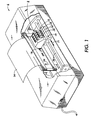
- FIG. 1 shows a perspective view of a full color ink jet printer which incorporates the ink supply container of the present invention.
- FIG. 2 is an exploded view of the ink container of FIG. 1 prior to being fluidly connected to a printhead.
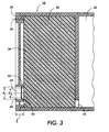
- FIG. 3 is a cross-sectional view of the container of FIG. 2.
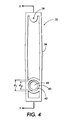
- FIG. 4 is an end view of the container of FIG. 2.
- FIG. 5 is an exploded view of the manifold connection to the ink container of FIG. 1.
- FIG. 6 is a cross-sectional side view of the ink outlet port of the container of FIGS. 3-5 just prior to installation of a manifold ink pipe.
- FIG. 7 is a cross-sectional side view of the ink outlet port of FIGS. 3-5 sealingly seated in the ink outlet port.
- FIG. 1 illustrates a perspective view of a full color thermal ink jet printer 6 which incorporates an ink container with improved sealing at the outlet port connection to an ink pipe manifold.
- Printer 6 includes an ink jet cartridge 8 comprising detachable ink containers 10, 12, 14, 16 fluidly connected to a segmented printhead 18.
- Cartridge 8 is counted on a carriage 19 supported on rails 20.
- the carriage rails are supported by a frame 22 of the ink jet printer 6.
- Each ink container comprises a detachable housing containing black or a colored ink for supply to printhead 18 via an ink manifold.
- the printhead 18 selectively expels droplets of ink under control of electrical signals received from a controller (not shown) of the printer 8 through an electrical cable (not shown).
- Printhead 18 includes a plurality of ink channels which carry ink from an associated containers 10, 12, 14, 16 to groupings, or segments of respective ink ejecting orifices or nozzles.
- the carriage 19 reciprocates back and forth along the carriage rails 20 in the direction of the arrow 21, the entire width traverse constitutes a scanning path. The actual printing zone is contained within the scanning path.
- a recording medium 34 such as a sheet of paper or a transparency
- droplets of ink are expelled from selected ones of the printhead 18 nozzles towards the sheet of paper.
- the recording medium 34 is held stationary.
- FIG. 2 shows an exploded view of one of the improved ink containers 10 prior to being fluidly connected to the associated printhead.
- FIG. 3 shows a cross-sectional side view of the container in an ink-loaded condition
- FIG. 4 is an end view of the container.
- container 10 includes a housing consisting of two compartments 30, 32.
- Compartment 30 has a porous material, in a preferred embodiment, foam member 34, which becomes saturated with ink moving from compartment 32 via internal port 33, compressively stored therein.
- a cover 36 is sealingly affixed to the open end of the container. Cover 36 has an air vent 38 and an ink outlet port 40 formed therein.
- port 40 has a length l (for this embodiment, the width of cover 36) and a diameter d 1 .
- port 40 has a sealing ring 42 formed interior to the port at a location along length l and having an internal diameter d 2 smaller than the port diameter d 1 .
- the function of ring 42 is discussed below.
- ring 42 is shown in FIG. 3 as being located near the ink input end of port 40, ring 42 could be located at other interior positions along length I even to the point of extending slightly into compartment 30.
- cover 36 and ring 42 are made of polypropylene, and the ring has a thickness between 0.1 mm and 0.3 mm, with ring 42 slightly angled towards the interior of the ink container; e.g., towards compartment 30.
- Port 40 has a diameter d 1 of 7.5 mm, and ring 42 has an inner diameter of d 2 of 6.10 mm.
- Length l is 2.72 mm, and ring 42 is positioned 2 mm from the port entrance.
- the ring 42 provides a seal against ink leakage into the printhead cartridge during and following insertion of ink tanks 10, 12, 14, 16. Referring to FIGS. 5, 6 and 7, FIG. 5 shows an exploded view of ink tanks 10-16 connected to a manifold member 52.
- Manifold member 52 comprises a plate 54 with ink pipes 56A-56D attached thereto.
- a sealing member 50 has a plurality of apertures 52A-52D therethrough and is seated on manifold 52 so as to fit snugly over the ink pipes 56A, 56B, 56C, 56D.
- member 50 is compressed against the exterior surface of cover 36 around the outlet ports of each container.
- FIG. 6 shows a cross-sectional view of one of the ink pipes 56A before insertion into port 40 of container 22. It is noted that the diameter d 3 of pipe 56A is larger than the inner diameter d 2 of ring 42.
- FIG. 7 shows ink pipe 56A seated within port 40 and extending into contact with foam member 34 a distance f of about 1.76 mm establishing a capillary flow of ink from the member through the ink pipe manifold and into the associated printhead.
- Ring 42 is compacted and is forced, or extruded, upwards by pipe 56A, establishing a sealing contact along interface C formed along the outer surface, or annulus, of pipe 56A and the inner compressed surface of ring 42.
- the ink container may comprise a single compartment in place of the two shown in the drawings.
Abstract
Description
- The present invention relates to ink recording devices and, more particularly, to an improved sealing connection between the outlet port of an ink supply container and a manifold connecting the ink to a printhead.
- Ink jet recording devices include one or more printheads which eject ink onto a print medium such as paper in controlled patterns of closely spaced dots. To form color images, multiple printheads are used, with each printhead being supplied with ink of a different color from an associated ink container.
- Thermal ink jet printing systems use thermal energy selectively produced by resistors located in capillary filled ink channels near channel terminating nozzles or orifices to vaporize momentarily the ink and form bubbles on demand. Each temporary bubble expels an ink droplet and propels it toward a recording medium. The printing system is generally incorporated in a carriage type printer. A carriage type printer generally has a relatively small printhead containing the ink channels and nozzles. The printhead is usually sealingly attached to an ink supply container and the combined printhead and container form a cartridge assembly which is reciprocated to print one swath of information at a time on a stationarily held recording medium, such as paper. After the swath is printed, the paper is stepped a distance equal to the height of the printed swath, so that the next printed swath will be contiguous therewith. The procedure is repeated until the entire page is printed.
- Ink from the ink supply container is drawn by capillary action through an outlet port in the container and into a manifold fluidly connecting ink to the printhead. The manifold supplies ink to the ink channels replenishing the ink after each ink ejection or firing from the associated nozzle.
- The ink container and printhead may be combined in an integral printhead cartridge assembly as is known in the art. With this arrangement, once the ink has been spent, the entire cartridge is replaced. Since the printhead is still useable, this is an inefficient design for many applications. An alternate arrangement is to connect an ink outlet port of a detachable ink container to a printhead via an ink manifold which includes an ink pipe which is seated within an outlet port. The pipe fluidly connects the ink, typically held in a porous material, to the printhead.
- One problem associated with the detached ink container design is ink leakage around the seated manifold ink pipe back into the manifold and printhead housing. The leakage occurs when the pipe touches or compresses the very saturated foam but before the cover is seated to the silicone seal. Various methods are known to provide ink sealing. U.S. Patent 5,519,425 discloses a thin polyester film having an aperture therethrough which is bonded to the ink container and to the printhead. U.S. Patent 5,488,401 shows an outer opening of an ink supply port sealed with a sealing member. This design allows the ink container to be replaced when ink has run out while retaining the still operable printhead.
- There is still a need for an improved sealing arrangement which reduces ink leakage after fluid connection to a printhead.
- The present invention is directed to an ink container which reduces the leakage occurring during and after flow connection of the container to a printhead. The improvement is enabled by forming the ink outlet port of the ink container with a first diameter and, internal to the port, forms a resilient sealing ring having a second, smaller inner diameter. When a manifold ink pipe is introduced into the ink outlet port, a sealing engagement is made at the interface of the sealing ring inner surface and the ink pipe outer surface. This sealing engagement provides a non-hermetic seal which prevents ink from the ink saturated porous material from flowing along the outer surface of the pipe back onto the manifold and printhead housing.
- More particularly, this invention relates to an ink supply container internally seating an ink absorbing member, said container having an ink outlet port; the ink container characterized by said outlet port having a length l and a diameter d1, said outlet port having a sealing ring formed interior thereto at a location along said length l, said ring having an internal diameter d2 smaller than said diameter d1.
- An embodiment of the present invention will now be described, by way of example, with reference to the accompanying drawings, in which:
- FIG. 1 shows a perspective view of a full color ink jet printer which incorporates the ink supply container of the present invention.
- FIG. 2 is an exploded view of the ink container of FIG. 1 prior to being fluidly connected to a printhead.
- FIG. 3 is a cross-sectional view of the container of FIG. 2.
- FIG. 4 is an end view of the container of FIG. 2.
- FIG. 5 is an exploded view of the manifold connection to the ink container of FIG. 1.
- FIG. 6 is a cross-sectional side view of the ink outlet port of the container of FIGS. 3-5 just prior to installation of a manifold ink pipe.
- FIG. 7 is a cross-sectional side view of the ink outlet port of FIGS. 3-5 sealingly seated in the ink outlet port.
- FIG. 1 illustrates a perspective view of a full color thermal ink jet printer 6 which incorporates an ink container with improved sealing at the outlet port connection to an ink pipe manifold. Printer 6 includes an ink jet cartridge 8 comprising
detachable ink containers printhead 18. Cartridge 8 is counted on acarriage 19 supported onrails 20. The carriage rails are supported by a frame 22 of the ink jet printer 6. Each ink container comprises a detachable housing containing black or a colored ink for supply toprinthead 18 via an ink manifold. Theprinthead 18 selectively expels droplets of ink under control of electrical signals received from a controller (not shown) of the printer 8 through an electrical cable (not shown). -
Printhead 18 includes a plurality of ink channels which carry ink from an associatedcontainers carriage 19 reciprocates back and forth along thecarriage rails 20 in the direction of thearrow 21, the entire width traverse constitutes a scanning path. The actual printing zone is contained within the scanning path. As the printhead cartridge 8 reciprocates back and forth along a print path and past arecording medium 34, such as a sheet of paper or a transparency, droplets of ink are expelled from selected ones of theprinthead 18 nozzles towards the sheet of paper. Typically, during each pass of thecarriage 19 therecording medium 34 is held stationary. At the end of each pass, therecording medium 34 is stepped in the direction of thearrow 36. For a more detailed explanation of the operation of printer 6 and for the details of the printhead construction, reference is hereby made to U.S. Patent No. 4,571,599, 4,833,491, and U.S. Patent No. Reissue 32,572, which are incorporated herein by reference. - FIG. 2 shows an exploded view of one of the improved
ink containers 10 prior to being fluidly connected to the associated printhead. FIG. 3 shows a cross-sectional side view of the container in an ink-loaded condition, and FIG. 4 is an end view of the container. Referring to FIGS. 2-4,container 10 includes a housing consisting of twocompartments Compartment 30 has a porous material, in a preferred embodiment,foam member 34, which becomes saturated with ink moving fromcompartment 32 viainternal port 33, compressively stored therein. Acover 36 is sealingly affixed to the open end of the container.Cover 36 has anair vent 38 and anink outlet port 40 formed therein. - As shown in FIGS. 3 and 4,
port 40 has a length l (for this embodiment, the width of cover 36) and a diameter d1 . According to the invention,port 40 has a sealingring 42 formed interior to the port at a location along length l and having an internal diameter d2 smaller than the port diameter d1 . The function ofring 42 is discussed below. Althoughring 42 is shown in FIG. 3 as being located near the ink input end ofport 40,ring 42 could be located at other interior positions along length I even to the point of extending slightly intocompartment 30. - In a preferred embodiment,
cover 36 andring 42 are made of polypropylene, and the ring has a thickness between 0.1 mm and 0.3 mm, withring 42 slightly angled towards the interior of the ink container; e.g., towardscompartment 30.Port 40 has a diameter d1 of 7.5 mm, andring 42 has an inner diameter of d2 of 6.10 mm. Length l is 2.72 mm, andring 42 is positioned 2 mm from the port entrance. Thering 42 provides a seal against ink leakage into the printhead cartridge during and following insertion ofink tanks manifold member 52.Manifold member 52 comprises aplate 54 withink pipes 56A-56D attached thereto. A sealingmember 50 has a plurality ofapertures 52A-52D therethrough and is seated onmanifold 52 so as to fit snugly over theink pipes member 50 is compressed against the exterior surface ofcover 36 around the outlet ports of each container. FIG. 6 shows a cross-sectional view of one of theink pipes 56A before insertion intoport 40 of container 22. It is noted that the diameter d3 ofpipe 56A is larger than the inner diameter d2 ofring 42. FIG. 7 showsink pipe 56A seated withinport 40 and extending into contact with foam member 34 a distance f of about 1.76 mm establishing a capillary flow of ink from the member through the ink pipe manifold and into the associated printhead.Ring 42 is compacted and is forced, or extruded, upwards bypipe 56A, establishing a sealing contact along interface C formed along the outer surface, or annulus, ofpipe 56A and the inner compressed surface ofring 42. - While the embodiment disclosed herein is preferred, it will be appreciated from this teaching that various alternative, modifications, variations or improvements therein may be made by those skilled in the art. For example, the ink container may comprise a single compartment in place of the two shown in the drawings.
Claims (6)
- An ink supply container (10) internally seating an ink absorbing member (34), said container having an ink outlet port (40); characterized in that the ink outlet port (40) has a length I and a diameter d1, and the said ink outlet port has a sealing ring (42) formed interior thereto at a location along said length l, said ring (42) having an internal diameter d2 smaller than said diameter d1.
- A container according to claim 1 wherein the sealing ring (42) is integrally molded as part of the outlet port (40).
- A container according to claim 1 or 2 wherein the sealing ring (42) is polypropylene with a thickness of between 0.1 mm and 0.3 mm.
- A print cartridge for an ink jet printer comprising, in combination:at least one ink container (10) having a compartment for holding an ink-impregnated porous member (34), and having an ink outlet port (40),a printhead (18),a manifold for fluidly connecting ink to said printhead (18), said manifold including an ink pipe (56A) seated in said outlet port (40) and contacting said porous member (34) so as to establish a capillary flow of ink through said manifold to said printhead, said ink pipe (56A) having a diameter d3, characterized in that the outlet port (40) has a diameter d1 slightly larger than the pipe diameter and a length l, and the outlet port (40) has a sealing ring member (42) formed along length l and with a diameter d2, smaller than d3, said sealing ring member (42) making sealing contact along the circumference of the seated ink pipe (56A).
- A print cartridge according to claim 4 wherein said ink manifold comprises a plurality of ink pipes (56A, 56B, 56C, 56D) which project into a plurality of ink containers (40), the print cartridge being used in a full color printer.
- A print cartridge according to claim 4 or 5 wherein said ring member is polypropylene having a thickness of between 0.1 mm and 0.3 mm.
Applications Claiming Priority (2)
| Application Number | Priority Date | Filing Date | Title |
|---|---|---|---|
| US5603198A | 1998-04-06 | 1998-04-06 | |
| US56031 | 1998-04-06 |
Publications (2)
| Publication Number | Publication Date |
|---|---|
| EP0949080A2 true EP0949080A2 (en) | 1999-10-13 |
| EP0949080A3 EP0949080A3 (en) | 2000-01-26 |
Family
ID=22001710
Family Applications (1)
| Application Number | Title | Priority Date | Filing Date |
|---|---|---|---|
| EP99301352A Withdrawn EP0949080A3 (en) | 1998-04-06 | 1999-02-24 | Ink container with improved sealing of ink container outlet port |
Country Status (3)
| Country | Link |
|---|---|
| EP (1) | EP0949080A3 (en) |
| JP (1) | JPH11320906A (en) |
| BR (1) | BR9902032A (en) |
Cited By (2)
| Publication number | Priority date | Publication date | Assignee | Title |
|---|---|---|---|---|
| WO2002085631A1 (en) * | 2001-04-20 | 2002-10-31 | Hewlett-Packard Company | Ink container configured to establish reliable fluidic connection to a receiving station |
| WO2007104187A1 (en) * | 2006-03-13 | 2007-09-20 | Jiajin Liu | Ink cartridge |
Families Citing this family (1)
| Publication number | Priority date | Publication date | Assignee | Title |
|---|---|---|---|---|
| JP3679213B2 (en) | 1996-01-22 | 2005-08-03 | 株式会社ブリヂストン | Heavy duty pneumatic radial tire |
Citations (5)
| Publication number | Priority date | Publication date | Assignee | Title |
|---|---|---|---|---|
| US4571599A (en) | 1984-12-03 | 1986-02-18 | Xerox Corporation | Ink cartridge for an ink jet printer |
| USRE32572E (en) | 1985-04-03 | 1988-01-05 | Xerox Corporation | Thermal ink jet printhead and process therefor |
| US4833491A (en) | 1988-06-15 | 1989-05-23 | Xerox Corporation | Thermal ink jet printer adapted to operate in monochrome, highlight or process color modes |
| US5488401A (en) | 1991-01-18 | 1996-01-30 | Seiko Epson Corporation | Ink-jet recording apparatus and ink tank cartridge thereof |
| US5519425A (en) | 1993-11-15 | 1996-05-21 | Xerox Corporation | Ink supply cartridge for an ink jet printer |
Family Cites Families (5)
| Publication number | Priority date | Publication date | Assignee | Title |
|---|---|---|---|---|
| SG46602A1 (en) * | 1992-01-28 | 1998-02-20 | Seiko Epson Corp | Ink tank cartridge and container therefor |
| JP3199092B2 (en) * | 1993-11-05 | 2001-08-13 | セイコーエプソン株式会社 | Ink cartridge for printer |
| JP3417434B2 (en) * | 1995-01-05 | 2003-06-16 | セイコーエプソン株式会社 | Ink cartridge for inkjet printer |
| DE19613654B4 (en) * | 1995-04-05 | 2006-04-13 | Seiko Epson Corp. | Ink jet recording apparatus |
| JPH10250104A (en) * | 1997-03-12 | 1998-09-22 | Seiko Epson Corp | Ink cartridge for ink-jet type recording apparatus, and its manufacture |
-
1999
- 1999-02-24 EP EP99301352A patent/EP0949080A3/en not_active Withdrawn
- 1999-03-26 JP JP8412999A patent/JPH11320906A/en not_active Withdrawn
- 1999-04-05 BR BR9902032-7A patent/BR9902032A/en not_active Application Discontinuation
Patent Citations (5)
| Publication number | Priority date | Publication date | Assignee | Title |
|---|---|---|---|---|
| US4571599A (en) | 1984-12-03 | 1986-02-18 | Xerox Corporation | Ink cartridge for an ink jet printer |
| USRE32572E (en) | 1985-04-03 | 1988-01-05 | Xerox Corporation | Thermal ink jet printhead and process therefor |
| US4833491A (en) | 1988-06-15 | 1989-05-23 | Xerox Corporation | Thermal ink jet printer adapted to operate in monochrome, highlight or process color modes |
| US5488401A (en) | 1991-01-18 | 1996-01-30 | Seiko Epson Corporation | Ink-jet recording apparatus and ink tank cartridge thereof |
| US5519425A (en) | 1993-11-15 | 1996-05-21 | Xerox Corporation | Ink supply cartridge for an ink jet printer |
Cited By (5)
| Publication number | Priority date | Publication date | Assignee | Title |
|---|---|---|---|---|
| WO2002085631A1 (en) * | 2001-04-20 | 2002-10-31 | Hewlett-Packard Company | Ink container configured to establish reliable fluidic connection to a receiving station |
| US6916088B2 (en) | 2001-04-20 | 2005-07-12 | Hewlett-Packard Development Company, L.P. | Ink container configured to establish reliable fluidic connection to a receiving station |
| CZ300043B6 (en) * | 2001-04-20 | 2009-01-14 | Hewlett-Packard Company | Replaceable ink container, method for forming a seal and replaceable printing component for an inkjet printing system |
| WO2007104187A1 (en) * | 2006-03-13 | 2007-09-20 | Jiajin Liu | Ink cartridge |
| US8029116B2 (en) | 2006-03-13 | 2011-10-04 | Jiajin Liu | Ink cartridge |
Also Published As
| Publication number | Publication date |
|---|---|
| EP0949080A3 (en) | 2000-01-26 |
| BR9902032A (en) | 2000-01-18 |
| JPH11320906A (en) | 1999-11-24 |
Similar Documents
| Publication | Publication Date | Title |
|---|---|---|
| US4571599A (en) | Ink cartridge for an ink jet printer | |
| US5821966A (en) | Ink jet cartridge with improved sealing between ink container and printhead | |
| US6644796B2 (en) | Fluid interconnect in a replaceable ink reservoir for pigmented ink | |
| US5966156A (en) | Refilling technique for inkjet print cartridge having two ink inlet ports for initial filling and recharging | |
| US5903292A (en) | Ink refill techniques for an inkjet print cartridge which leave correct back pressure | |
| US6457821B1 (en) | Filter carrier for protecting a filter from being blocked by air bubbles in an inkjet printhead | |
| NZ280044A (en) | Multi-chambered ink cartridge for ink jet printer | |
| JP4146575B2 (en) | Printing device | |
| US6196671B1 (en) | Ink-jet cartridge for an ink jet printer having air ingestion control | |
| JPH047306B2 (en) | ||
| JP4185578B2 (en) | Fluid adapter for inkjet print cartridge | |
| JP4165725B2 (en) | Ink container | |
| KR19990083529A (en) | Inkjet ink containment using particles for backpressure transition | |
| KR100901952B1 (en) | Ink container configured to establish reliable fluidic connection to a receiving station | |
| US6843557B2 (en) | Liquid jetting device and liquid supplying method in use for the liquid jetting device | |
| EP0875385B1 (en) | An ink delivery that utilizes a separate insertable filter carrier | |
| US6540323B1 (en) | Snout-encompassing capping system for inkjet printheads | |
| US6827422B2 (en) | Liquid suction apparatus for liquid ejecting head and liquid ejecting apparatus | |
| EP0949080A2 (en) | Ink container with improved sealing of ink container outlet port | |
| JPH11320907A (en) | Ink feed container | |
| US11298944B2 (en) | Tanks for print cartridge | |
| JPH11342625A (en) | Ink jet recording apparatus | |
| JPH1158758A (en) | Sealing device | |
| MXPA99002861A (en) | Ink supply recipient with better gate seal | |
| MXPA98001297A (en) | Ink jet cartridge with an improved seal in the container of the ink and printer head |
Legal Events
| Date | Code | Title | Description |
|---|---|---|---|
| PUAI | Public reference made under article 153(3) epc to a published international application that has entered the european phase |
Free format text: ORIGINAL CODE: 0009012 |
|
| AK | Designated contracting states |
Kind code of ref document: A2 Designated state(s): DE FR GB |
|
| AX | Request for extension of the european patent |
Free format text: AL;LT;LV;MK;RO;SI |
|
| PUAL | Search report despatched |
Free format text: ORIGINAL CODE: 0009013 |
|
| AK | Designated contracting states |
Kind code of ref document: A3 Designated state(s): AT BE CH CY DE DK ES FI FR GB GR IE IT LI LU MC NL PT SE |
|
| AX | Request for extension of the european patent |
Free format text: AL;LT;LV;MK;RO;SI |
|
| 17P | Request for examination filed |
Effective date: 20000726 |
|
| AKX | Designation fees paid |
Free format text: DE FR GB |
|
| STAA | Information on the status of an ep patent application or granted ep patent |
Free format text: STATUS: THE APPLICATION HAS BEEN WITHDRAWN |
|
| 18W | Application withdrawn |
Withdrawal date: 20020723 |