EP0949842A2 - Communications system and method of controlling same - Google Patents
Communications system and method of controlling same Download PDFInfo
- Publication number
- EP0949842A2 EP0949842A2 EP19990400378 EP99400378A EP0949842A2 EP 0949842 A2 EP0949842 A2 EP 0949842A2 EP 19990400378 EP19990400378 EP 19990400378 EP 99400378 A EP99400378 A EP 99400378A EP 0949842 A2 EP0949842 A2 EP 0949842A2
- Authority
- EP
- European Patent Office
- Prior art keywords
- communications
- connection device
- qualities
- connection
- communication
- Prior art date
- Legal status (The legal status is an assumption and is not a legal conclusion. Google has not performed a legal analysis and makes no representation as to the accuracy of the status listed.)
- Withdrawn
Links
Images


Classifications
-
- H—ELECTRICITY
- H04—ELECTRIC COMMUNICATION TECHNIQUE
- H04Q—SELECTING
- H04Q11/00—Selecting arrangements for multiplex systems
- H04Q11/04—Selecting arrangements for multiplex systems for time-division multiplexing
- H04Q11/0428—Integrated services digital network, i.e. systems for transmission of different types of digitised signals, e.g. speech, data, telecentral, television signals
- H04Q11/0478—Provisions for broadband connections
-
- H—ELECTRICITY
- H04—ELECTRIC COMMUNICATION TECHNIQUE
- H04L—TRANSMISSION OF DIGITAL INFORMATION, e.g. TELEGRAPHIC COMMUNICATION
- H04L12/00—Data switching networks
- H04L12/54—Store-and-forward switching systems
- H04L12/56—Packet switching systems
- H04L12/5601—Transfer mode dependent, e.g. ATM
- H04L2012/5629—Admission control
-
- H—ELECTRICITY
- H04—ELECTRIC COMMUNICATION TECHNIQUE
- H04L—TRANSMISSION OF DIGITAL INFORMATION, e.g. TELEGRAPHIC COMMUNICATION
- H04L12/00—Data switching networks
- H04L12/54—Store-and-forward switching systems
- H04L12/56—Packet switching systems
- H04L12/5601—Transfer mode dependent, e.g. ATM
- H04L2012/5638—Services, e.g. multimedia, GOS, QOS
Definitions
- This invention relates to a communications system and to a method of controlling the same.
- a system connected to a communications network to perform communication is so adapted that the user selects the communications network in advance to carry out communication.
- the selection is made in conformity with the transmission quality requirement necessitated by the type of data handled by the system.
- Examples of networks that can be selected are a PSTN (Public Switched Telephone Network), ISDN (Integrated Services Digital Network), PSPDN (Packet Switching Public Data Network) and the Internet.
- a system requiring little delay as in the case of a videoconference system is connected to a PSTN or ISDN, whereas a system that allows some delay, such as a system for data transfer and e-mail, is connected to a PSPDN or the Internet.
- An object of the present invention is to provide a communications system in which the communications quality of a system can be changed in appropriate fashion in dependence upon the status of a network.
- Another object of the present invention is to make it possible to change a communications quality requirement automatically.
- Another object of the present invention is to select an optimum route based upon a changed communications quality requirement.
- a further object of the present invention is to assign priorities to communications qualities.
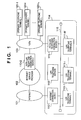
- Fig. 1 is a block diagram of a communications according to a first embodiment of the present invention, namely a telephone system that makes telephone conversion possible by making a connection for voice communication in accordance with TCP/IP over a LAN or the Internet, etc., and for telephone communication over a public network such as a PSTN.
- Shown in Fig. 1 are the Internet, indicated at 101; an Internet service provider 102, which provides an Internet connection service; and a PSTN-LAN telephone connection device 113-2, which is connected to a PSTN 103 and to a LAN within the Internet service provider 102 and has a function for controlling connection to the PSTN 103 and a function for effecting a conversion between telephone speech on the PSTN 103 and voice data of TCP/IP.
- the PSTN 103 is an ordinary analog telephone network.
- a telephone system (referred to as a "LAN telephone system” below) 114 is configured in such a manner that voice telephone conversion is carried out in accordance with a protocol such as TCP/IP by a device that has been connected to a LAN 115 in compliance with IEEE 802.3, etc.
- Shown at 120-i is an ordinary telephone terminal, which is a telephone terminal that is generally connected to the PSTN 103.
- the LAN telephone system 114 includes an Internet connection device 112 connecting the LAN 115 and the Internet 101 via a leased line and having a routing function, a security function and a proxy function; a PSTN-LAN telephone connection device 113-1 having functions similar to those of the PSTN-LAN telephone connection device 113-2; a LAN telephone terminal 111-i, which is connected to the LAN 115 and has voice input/output units such as a microphone, speaker and handset and a user interface, for performing LAN telephone connection control in response to instructions from the user as well as processing for transferring voice data during a telephone conversion; and a LAN telephone server 110 for managing the LAN telephone terminal 111-i.
- an Internet connection device 112 connecting the LAN 115 and the Internet 101 via a leased line and having a routing function, a security function and a proxy function
- a PSTN-LAN telephone connection device 113-1 having functions similar to those of the PSTN-LAN telephone connection device 113-2
- a LAN telephone terminal 111-i which is connected to
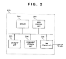
- Fig. 2 is a block diagram showing the LAN telephone server 110.
- the latter includes a LAN controller 205 in compliance with IEEE 802.3 or the like; a permanent storage unit 204 such as a hard disk; a display unit 202 such as a CRT display; a key input unit 203 such as a keyboard and mouse; and a main control unit 201 composed of a CPU, ROM and RAM, etc., for administering various control operations.
- a LAN controller 205 in compliance with IEEE 802.3 or the like
- a permanent storage unit 204 such as a hard disk
- a display unit 202 such as a CRT display
- a key input unit 203 such as a keyboard and mouse
- main control unit 201 composed of a CPU, ROM and RAM, etc., for administering various control operations.
- the CPU of the main control unit 201 performs various control operations in accordance with programs stored in the ROM.
- Fig. 3 is a block diagram of the LAN telephone terminal 111-i.
- the latter includes a main control unit 301 composed of a CPU, ROM and RAM, etc., for administering various control operations, wherein the CPU performs various control operations in accordance with programs stored in the ROM; a permanent storage unit 302 such as a hard disk; a display unit 303 such as a CRT display; a LAN controller 304 in compliance with IEEE 802.3 or the like; a key input unit 305 such as a keyboard and mouse; and a voice input/output unit 306, to which a microphone and speaker of a handset or the like are connected, for converting analog information to digital information by a codec or the like and inputting/outputting voice data.
- a main control unit 301 composed of a CPU, ROM and RAM, etc., for administering various control operations, wherein the CPU performs various control operations in accordance with programs stored in the ROM
- a permanent storage unit 302 such as a hard disk
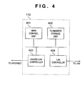
- Fig. 4 is a block diagram of the Internet connection device 112.
- the latter includes a main control unit 401 composed of a CPU, ROM and RAM, etc., wherein the CPU performs various control operations in accordance with programs stored in the ROM; a permanent storage unit 402 such as a hard disk; a LAN controller 404 in compliance with IEEE 802.3 or the like; and a leased-line controller 403 having a leased-line connection interface and a data transmission interface.
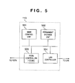
- Fig. 5 is a block diagram of the PSTN-LAN telephone connection device 113.
- the latter includes a main control unit 501 composed of a CPU, ROM and RAM, etc., wherein the CPU performs various control operations in accordance with programs stored in the ROM; a permanent storage unit 502 such as a hard disk; a LAN controller 504 in compliance with IEEE 802.3; and a PSTN controller 503, which performs connection control with respect to the PSTN 103 and has a codec so that analog information from the PSTN can be converted to digital information.
- a main control unit 501 composed of a CPU, ROM and RAM, etc., wherein the CPU performs various control operations in accordance with programs stored in the ROM
- a permanent storage unit 502 such as a hard disk
- LAN controller 504 in compliance with IEEE 802.3
- PSTN controller 503 which performs connection control with respect to the PSTN 103 and has a codec so that analog information from the PSTN can be converted to digital information.
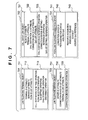
- Fig. 7 is a diagram showing the structure of control data in the LAN telephone system 114.
- the structure of control data of the LAN telephone terminal 111-i is indicated at 701.
- Numeral 702 denotes the structure of data in the flow of call data, namely flow of data in a voice telephone conversation.
- Numeral 703 denotes the structure of control data of the LAN telephone server 110, and 704 denotes the structure of control data of the PSTN-LAN telephone connection device 113.
- Control attribute data 712 in the LAN telephone terminal 111-i in the data structure 701 comprises a terminal ID for self-identification, a server ID which identifies the server that is the object of management, and a flow ID list which identifies call data flow generated in correspondence with a call destination ID that has been set.
- Control processing 713 comprises processing for setting the call destination ID, processing for setting QoS(Quality of Service), which stipulates the communications quality requirement, flow selection processing for selecting, from the flow ID list, a flow which is the object of call origination or QoS setting, call origination processing and disconnect processing.
- Control attribute data 722 having the call data flow in 702 comprises a flow ID for self-identification, a terminal ID which identifies a terminal serving as the source of call data, a call destination ID which identifies the destination of call data, a connection device ID of a connection device which performs a relay operation, and a QoS list which stipulates the communications quality requirement.
- Control processing 723 comprises processing for referring to a call destination ID, processing for setting or referring to a connection device ID, and processing for setting or referring to the QoS list.
- Control attribute data 732 possessed by the LAN telephone server 110 in 703 comprises a server ID for self-identification, an ID List of connection devices managed by this server, and an ID list of terminals managed by this server.
- Control processing 733 comprises connection device search processing executed to search for a connection device that satisfies a required QoS.
- Control attribute data 742 possessed by the PSTN telephone connection device in 704 comprises a server ID for self-identification, PSTN connection status which holds information indicating whether an accommodated line is in use or not, and assured QoS stipulating the communications quality assured by this device.
- Control processing 743 comprises resource acquisition processing for requesting the network, to which this device is connected, to reserve the resources that satisfy the QoS required, resource release processing for releasing reserved resources, connect processing for performing connection control, and assured QoS reference processing for referring to an assured QoS.
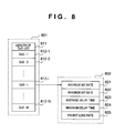
- numeral 801 is a block diagram of a QoS list retained in the control data 722 of the call data flow shown in Fig. 7.
- the list is composed of a plurality of QoSs (812-1, ⁇ , 812-N) and a length 811 indicating the number thereof.
- Any QoS 812-i is composed of average bit rate 821, maximum bit rate 822, average delay time 823, maximum delay time 824 and packet loss rate 825.
- the assured QoS of control data attribute 742 in the connection device data structure 704 also has a composition similar to that of QoS 812-i.
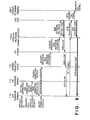
- any LAN telephone terminal 111-i in the LAN telephone system 114 originates a call to any ordinary telephone terminal 120-i, which is connected to the PSTN 103, by placing a call to the PSTN 103 via the Internet connection device 112, Internet 101 and PSTN-LAN telephone connection device 113-2 of the Internet service provider 102.
- a call destination ID is set at the LAN telephone terminal 111-i, this call destination is selected by flow selection processing and a call originating operation is performed.
- the LAN telephone terminal 111-i reads out QoS-1, on the assumption that the QoS specified as being of first priority by QoS list reference processing of call data flow 702 and the QoSs of Fig. 8 are arranged in decreasing order of priority, and initiates connection device search processing in the LAN telephone server 110 (901).
- the LAN telephone server 110 searches for a PSTN-LAN telephone connection device 113 that is capable of satisfying QoS-1, which has been reported by the LAN telephone terminal 111-i, and sends the result back to the LAN telephone terminal 111-i as the connection device ID list (902).
- the LAN telephone terminal 111-i selects a connection device ID arbitrarily from the connection device ID list that has been obtained. In the description rendered here, it is assumed that the PSTN-LAN telephone connection device 113-2 has been selected. Resource acquisition processing is executed with respect to the PSTN-LAN telephone connection device 113-2. A resource acquisition message that accompanies the resource acquisition processing arrives at the PSTN-LAN telephone connection device 113-2 while resource acquisition is verified at the Internet connection device 112 and Internet 101 along the route (903 - 905). The PSTN-LAN telephone connection device 113-2 sends an outgoing call signal 906 to the PSTN 103 and sends back an answer 908 to the effect that resource acquisition has been allowed by confirmation of a dial tone 907.
- the LAN telephone terminal 111-i executes processing for connection to the call destination ID in regard to the PSTN-LAN telephone connection device 113-2 (911).
- the PSTN-LAN telephone connection device 113-2 sends a dialing signal 912 to the PSTN 103 based upon dialing information specified by the call destination ID.
- the PSTN 103 sends an incoming-call signal 913 to the ordinary telephone terminal 120-i specified by the dialing number and sends a ring-back tone 914 to the PSTN-LAN telephone connection device 113-2.
- the latter converts the ring-back tone 914, which is an analog signal, to voice data 915 in accordance with TCP/IP and then sends this data to the LAN telephone terminal 111-i.
- the LAN telephone terminal 111-i Upon receiving the ring-back tone 915, which is now the voice data in accordance with TCP/IP, the LAN telephone terminal 111-i converts this back to an analog signal and outputs the signal from a voice output unit such as a speaker.
- an answer signal 916 is sent to the PSTN 103.
- the latter receives this signal and sends an answer signal 917, which is sensed by the PSTN-LAN telephone connection device 113-2.
- the latter then sends an answer 918 to the LAN telephone terminal 111-i.
- the latter receives the answer 918 and establishes a telephone call 919.
- the PSTN 103 is released (920) and a busy signal 921 sent from the PSTN 103 in response is converted to a busy signal 922 in accordance with TCP/IP by the PSTN-LAN telephone connection device 113-2.
- the busy signal 922 is sent to the LAN telephone terminal 111-i.
- Resource release processing is started with respect to the PSTN-LAN telephone connection device 113-2 by a disconnect operation performed at the LAN telephone terminal 111-i. Resource release reaches the PSTN-LAN telephone connection device 113-2 (923 - 925) while resource release processing is executed by the Internet connection device 112 and Internet 101 along the route.
- verification 927 is sent back and call processing is terminated.
- connection-device search processing 1101 under the conditions of QoS-1 is started with respect to the LAN telephone server 110 by setting the destination ID and originating a call at LAN telephone terminal 111-i, and a list 1102 of connection device IDs is obtained. If it is assumed that only the PSTN-LAN telephone connection device 113-2 connected via the Internet 101 has been selected from the connection device ID list in a manner similar to that shown in Figs. 9 and 10, resource acquisition processing is executed successively by the Internet connection device 112 and Internet 101 (1103, 1104). In a case where resources adequate enough to satisfy the required communications quality QoS-1 are difficult to reserve in the Internet 101, the latter sends back a refusal 1105.
- the refusal 1105 arrives at the LAN telephone terminal 111-i as refusal 1106 via the Internet connection device 112.
- the LAN telephone terminal 111-i refers to the QoS list of the communications data flow 702 and reads out the QoS having the next highest priority.
- Connection-device search processing 1107 is executed under QoS-2 through a procedure similar to that in the case of QoS-1, an ID list 1108 of connection devices is acquired and a resource acquisition operation 1109 is performed with respect to the PSTN-LAN telephone connection device 113-1 selected as the device that satisfies QoS-2.
- the PSTN-LAN telephone connection device 113-1 sends an outgoing call signal 1110 to the PSTN 103, acquires a dial tone 1111 and sends permission 1112 to the LAN telephone terminal 111-i. Thereafter, processing is executed through a procedure similar to that of 911 - 919 of Figs. 9 and 10 until call establishment 1121. In a case where a disconnect operation is performed first at LAN telephone terminal 111-i when the call 1121 is completed, resource release processing is executed with respect to the PSTN-LAN telephone connection device 113-1, the resources of the PSTN 103 are released (1123) and verification 1125 is sent back. Further, owing to the release of resources of the PSTN 103, a busy signal 1124 is sent to the ordinary telephone terminal 120-i that engaged in the call and the PSTN 103 is released.
- control proceeds to call destination ID setting processing (Fig. 14) (S1311) in response to detection of a call destination ID setting operation ("YES” at step S1301); control proceeds to QoS setting processing (Fig. 15) (S1321) in response to detection of a QoS setting operation ("YES” at step S1302); and control proceeds to call origination processing (Figs. 16A and 16B) (S1331) in response to detection of a call originating operation ("YES" at step S1303). If a flow selection operation is detected (“YES” at step S1304), a selection (S1341) of call data flow is made and control returns to LAN telephone terminal processing (S1305). If nothing is detected ("NO" at steps S1301 - S1304), then LAN telephone terminal processing is repeated (S1305).
- call destination ID setting processing shown in Fig. 14 it is determined at the time of the call ID setting operation whether a call destination ID delivered is unauthorized as a call destination ID. If the ID is not unauthorized ("NO" at step S1401), call data flow 702 is generated (S1402) and control returns to LAN telephone terminal processing (Fig. 13). If the call destination ID is unauthorized ("YES" at step S1401), an ID setting value error is display (S1411) and control returns to LAN telephone terminal processing (Fig. 13) (S1412).
- step S1504 If the input data is unauthorized ("YES” at step S1504), an input error display is presented (S1541) and control returns to the processing (S1503) for acquiring an addition/change input. If the input data is not unauthorized ("NO” at step S1504), then QoS change processing is executed with respect to the call data flow (S1505) and control returns to LAN telephone terminal processing (Fig. 13) (S1506).
- call origination processing it is determined at the time of a call originating operation whether a call data flow has been selected (S1601). If a call data flow has not been selected ("NO" at step S1601), call data flow selection is performed (S1611) and control returns to call origination processing (S1619). If call data flow has been selected ("YES" at step S1601), the QoS list of this call data flow is referred to and the QoS of first priority is read out (S1602).
- connection device ID list acquired from the LAN telephone server 110 is blank ("YES” at step S1605), an origination processing error display is presented (S1651) and control returns to LAN telephone terminal processing (Fig. 13) (S1659). If the connection device ID list is not blank (“NO” at step S1605), one connection device ID is selected (e.g., randomly) and is removed from the connection device ID list (S1606).
- connection device ID is obtained ("NO” at step S1607)
- a resource acquisition operation capable of satisfying the selected QoS is started in regard to this connection device (S1608). If acquisition of resources is allowed (“YES” at step S1609), an operation for making a connection to the call destination ID obtained from the call data flow is started (S1610) and control proceeds to ringing-in-progress processing (S1690). If acquisition of resources has been refused (“NO” at step S1609), another connection device ID is selected from the connection device ID list again (S1606).
- connection device ID is not obtained ("YES” at step S1607), i.e., if resource acquisition has been refused with respect to the entire connection device ID list, the QoS having the next highest priority is read out of the QoS list (S1671) and the search for a connection device is started again (S1604). If a QoS having this next highest priority does not exist (“YES” at step S1603), a call origination processing error display is presented (S1631) and control returns to LAN telephone terminal processing (Fig. 13) (S1639).
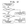
- control proceeds to disconnect processing (Fig. 19) (S1711) if a disconnect operation is sensed ("YES” at step S1701). In an answer is received (“YES” at step S1702), control proceeds to connection-in-progress processing (Fig. 18) (S1721). If a disconnect operation is not sensed and an answer is not received ("NO" at steps S1701, S1702), then ringing-in-progress processing is repeated (S1703).
- connection-in-progress processing illustrated in Fig. 18 control proceeds to disconnect processing (Fig. 19) (S1811) if a disconnect operation is sensed ("YES” at step S1801). If a disconnect operation is not sensed ("NO” at step S1801), then connection-in-progress processing is repeated (S1802).
- disconnect processing shown in Fig. 19 a resource release operation is performed with respect to the connection device currently connected (S1901), verification is received ("YES” at step 1903) and control returns to LAN telephone terminal processing (Fig. 13) (S1904). If verification is not received ("NO” at step S1903), a disconnect processing error is displayed (S1931) and control returns to LAN telephone terminal processing (Fig. 13) (S1904).
- connection device search processing (Fig. 21) ("YES” at step S2011) if a connection device search operation is sensed. If this operation is not sensed ("NO” at step S2001), then LAN telephone server processing is repeated (S2002).
- connection device search processing illustrated in Fig. 21 first a retrieved connection device ID list, which is the result of a search, is initialized (S2101) and a connection device ID is acquired from a self-managed connection device ID (S2102). When a connection device ID is acquired ("NO" at step S2103), reference is made to the assured QoS of this connection device (S2104).
- connection device IDs capable of being acquired are no longer available ("YES" at step S2103)
- the retrieved connection device ID list is posted to the LAN telephone terminal 111 that requested the connection device search (S2131) and control returns to LAN telephone server processing (Fig. 20) (S2139).
- control proceeds to PSTN resource acquisition processing (Fig. 23) (S2219) if a resource acquisition operation performed at the LAN telephone terminal 111 is sensed ("YES" at step S2201); to PSTN connect processing (Fig. 24) (S2229) if a connection operation performed at the LAN telephone terminal 111 is sensed ("YES" at step S2202); and to PSTN resource release processing (Fig. 25) (S2239) if a resource release operation performed at the LAN telephone terminal 111 is sensed ("YES" at step S2203). Otherwise (“NO" at steps S2201 - S2203), processing executed by the PSTN-LAN telephone connection device is repeated (S2209).
- an idle outside line is selected (S2301) from the PSTN connection status at 742 in Fig. 7 holding information such as whether the aforementioned accommodated line is in use. If an idle outside line is obtained ("NO” at step S2302), an outgoing call signal is sent to this outside line (S2303). If a dial tone obtained from a network is sensed in response to the outgoing call signal ("YES" at step S2304), permission is sent back to the LAN telephone terminal 111 (S2305) and control returns to the processing (Fig. 22) performed by the PSTN-LAN telephone connection device (S2309).
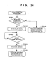
- PSTN connect processing shown in Fig. 24 first it is determined whether resources have been reserved, i.e., whether an outside line has been acquired and a call originated (S2401). If resources have not be reserved ("NO" at step S2401), control returns to the processing (Fig. 22) performed by the PSTN-LAN telephone connection device (S419). If resources have been reserved ("YES” at step S2401), a dialing signal based upon a call destination ID obtained from the LAN telephone terminal 111 at the time of processing start-up is sent (S2402) and an answer signal from the other party's telephone terminal is awaited ("NO" at step S2403).
- communications quality required for communications such as average bit rate, maximum bit rate, average delay time, maximum delay time and packet loss rate can be selected flexibly in dependence upon the status of the network.
- selection of communication quality is performed automatically. This makes it possible to perform communication at optimum communications quality in a manner transparent to the user.
- the user is capable of setting a plurality of communications qualities having different priorities.
- optimum communication quality can be selected.
- the optimum network can be selected automatically.
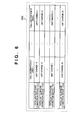
- the cost calculation table 600 shown in Fig. 6 is capable of being referred to by the LAN telephone server 110 and retains, in a table format, telephone call charges based upon the PSTN-LAN telephone connection devices 113-1 to 113-N, which are managed by the LAN telephone server 110, and call destination ID areas (toll numbers in this case).
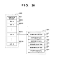
- the QoS list 803 of Fig. 26 is the result of adding, onto the QoS list 801 of Fig. 8, an upper limit 841 on cost permitted in order to obtain the particular QoS.
- the operation involved will now be described.
- the basic operation which is similar to that of the first embodiment, is to change the decision (S2105), as to whether the required QoS is satisfied or not, in the connection device search processing (Fig. 21) of the LAN telephone server 110 in such a manner that use is made of the cost calculation table 600 and QoS list 803. That is, in the processing (S2105) for judging whether the requirement is satisfied or not, the desired unit charge is read out of the cost calculation table 600 and a decision is rendered to the effect that the required QoS is satisfied if two conditions are met, namely that the value of the desired unit charge is less than the upper limit 841 on cost and that the conditions set forth in the first embodiment are satisfied.
- the functions of the first and second embodiments are supplemented by reporting to the user the communications quality that has been automatically selected. More specifically, the content of the automatically selected communications quality may be displayed on the display unit of a LAN telephone terminal so that the user may refer to it when setting the QoS.
- QoS-1 to QoS-N of Figs. 8 and 26 can be associated with levels 1 to N in the order of priority and the level that corresponds to the automatically selected QoS can be displayed.
- communications quality required for communications such as average bit rate, maximum bit rate, average delay time, maximum delay time and packet loss rate can be selected flexibly and optimally in dependence upon the status of the network.
- the selection of communications quality is performed automatically. This makes it possible to perform communication at optimum communications quality in a manner transparent to the user.
- the user is capable of setting a plurality of communications qualities having different priorities.
- optimum communication quality can be selected.
- the optimum network can be selected automatically.
Abstract
Description
- This invention relates to a communications system and to a method of controlling the same.
- A system connected to a communications network to perform communication is so adapted that the user selects the communications network in advance to carry out communication. The selection is made in conformity with the transmission quality requirement necessitated by the type of data handled by the system. Examples of networks that can be selected are a PSTN (Public Switched Telephone Network), ISDN (Integrated Services Digital Network), PSPDN (Packet Switching Public Data Network) and the Internet.
- By way of example, a system requiring little delay as in the case of a videoconference system is connected to a PSTN or ISDN, whereas a system that allows some delay, such as a system for data transfer and e-mail, is connected to a PSPDN or the Internet.
- However, in a case where a system that employs a coding/compression scheme conforming to the connected communications network to perform voice/image communication by a protocol related to the TCP/IP (Transmission Control Protocol / Internet Protocol) is configured for a network such as a PSTN, ISDN or Internet, the prior art described above is such that the network to which the connection is to be established must be decided beforehand and the related settings must be made. For example, there are cases where it is desired to perform long-distance communication via the Internet and short-distance communication via an ISDN. In such cases, communication terminal settings must be changed by manual input whenever communication is performed. There are also cases where it is desired to transmit by a PSTN line, even for short-distance communication, because an ISDN line is busy. And there are instances where it is desired to communicate directly via an ISDN line because of heavy traffic congestion on the Internet and an inability to obtain satisfactory quality for communication owing to the time delay. In all of these cases the operator must change the connections and data settings each time. This is a very troublesome task.
- More generally, with a system of the type that is connected to a network, typified by an ATM network, in which it is usually possible to reserve the resources that satisfy the required communications quality, what can and cannot be communicated upon relaxing the quality requirement must be selected if resources that will make it possible to obtain the sought communications quality cannot be reserved. Even achieving the downgrading of the communications quality requirement demands that the operator change the requirement manually. There are many quality-related items, such as delay, loss and bandwidth, and the operator must decide which item is to undergo the reduction in quality and in what way. However, the prior art is such that such instances cannot be dealt with in a flexible manner.
- An object of the present invention is to provide a communications system in which the communications quality of a system can be changed in appropriate fashion in dependence upon the status of a network.
- Another object of the present invention is to make it possible to change a communications quality requirement automatically.
- Another object of the present invention is to select an optimum route based upon a changed communications quality requirement.
- A further object of the present invention is to assign priorities to communications qualities.
- Other features and advantages of the present invention will be apparent from the following description taken in conjunction with the accompanying drawings, in which like reference characters designate the same or similar parts throughout the figures thereof.
-
- Fig. 1 is a block diagram showing a communications system in accordance with a first embodiment of the present invention;
- Fig. 2 is a block diagram showing a LAN telephone server according to the embodiment;
- Fig. 3 is a block diagram showing a LAN telephone terminal according to the embodiment;
- Fig. 4 is a block diagram showing an Internet connection device according to the embodiment;
- Fig. 5 is a block diagram showing a PSTN-LAN telephone connection device according to the embodiment;
- Fig. 6 is a cost calculation table according to a second embodiment of the present invention;
- Fig. 7 is a diagram showing the structure of system control data according to the embodiment;
- Fig. 8 is a diagram showing the structure of communications quality data according to the first embodiment;
- Fig. 9 is a sequence diagram at the time of a first-priority connection in a communications system according to the embodiment;
- Fig. 10 is a sequence diagram at the time of the first-priority connection in a communications system according to the embodiment;
- Fig. 11 is a sequence diagram at the time of a second-priority connection in a communications system according to the embodiment;
- Fig. 12 is a sequence diagram at the time of the second-priority connection in a communications system according to the embodiment;
- Fig. 13 is a flowchart of LAN telephone terminal processing according to the embodiment;
- Fig. 14 is a flowchart of processing for setting a call destination ID according to the embodiment;
- Fig. 15 is a flowchart of processing for setting a QoS according to the embodiment;
- Figs. 16A and 16B are flowcharts of call origination processing according to the embodiment;
- Fig. 17 is a flowchart of ringing-in-progress processing according to the embodiment;
- Fig. 18 is a flowchart of connection-in-progress processing according to the embodiment;
- Fig. 19 is a flowchart of disconnect processing according to the embodiment;
- Fig. 20 is a flowchart of LAN telephone server processing according to the embodiment;
- Fig. 21 is a flowchart of connection device search processing according to the embodiment;
- Fig. 22 is a flowchart of PSTN-LAN telephone connection device processing according to the embodiment;
- Fig. 23 is a flowchart of PSTN resource acquisition processing according to the embodiment;
- Fig. 24 is a flowchart of PSTN connect processing according to the embodiment;
- Fig. 25 is a flowchart of PSTN resource release processing according to the embodiment; and
- Fig 26 is a diagram showing the structure of communications quality data according to the second embodiment of the present invention.
-
- Fig. 1 is a block diagram of a communications according to a first embodiment of the present invention, namely a telephone system that makes telephone conversion possible by making a connection for voice communication in accordance with TCP/IP over a LAN or the Internet, etc., and for telephone communication over a public network such as a PSTN. Shown in Fig. 1 are the Internet, indicated at 101; an
Internet service provider 102, which provides an Internet connection service; and a PSTN-LAN telephone connection device 113-2, which is connected to aPSTN 103 and to a LAN within theInternet service provider 102 and has a function for controlling connection to thePSTN 103 and a function for effecting a conversion between telephone speech on thePSTN 103 and voice data of TCP/IP. The PSTN 103 is an ordinary analog telephone network. A telephone system (referred to as a "LAN telephone system" below) 114 is configured in such a manner that voice telephone conversion is carried out in accordance with a protocol such as TCP/IP by a device that has been connected to aLAN 115 in compliance with IEEE 802.3, etc. Shown at 120-i is an ordinary telephone terminal, which is a telephone terminal that is generally connected to the PSTN 103. TheLAN telephone system 114 includes anInternet connection device 112 connecting theLAN 115 and the Internet 101 via a leased line and having a routing function, a security function and a proxy function; a PSTN-LAN telephone connection device 113-1 having functions similar to those of the PSTN-LAN telephone connection device 113-2; a LAN telephone terminal 111-i, which is connected to theLAN 115 and has voice input/output units such as a microphone, speaker and handset and a user interface, for performing LAN telephone connection control in response to instructions from the user as well as processing for transferring voice data during a telephone conversion; and aLAN telephone server 110 for managing the LAN telephone terminal 111-i. - Fig. 2 is a block diagram showing the
LAN telephone server 110. The latter includes aLAN controller 205 in compliance with IEEE 802.3 or the like; apermanent storage unit 204 such as a hard disk; adisplay unit 202 such as a CRT display; akey input unit 203 such as a keyboard and mouse; and amain control unit 201 composed of a CPU, ROM and RAM, etc., for administering various control operations. - The CPU of the
main control unit 201 performs various control operations in accordance with programs stored in the ROM. - Fig. 3 is a block diagram of the LAN telephone terminal 111-i. The latter includes a
main control unit 301 composed of a CPU, ROM and RAM, etc., for administering various control operations, wherein the CPU performs various control operations in accordance with programs stored in the ROM; apermanent storage unit 302 such as a hard disk; adisplay unit 303 such as a CRT display; aLAN controller 304 in compliance with IEEE 802.3 or the like; akey input unit 305 such as a keyboard and mouse; and a voice input/output unit 306, to which a microphone and speaker of a handset or the like are connected, for converting analog information to digital information by a codec or the like and inputting/outputting voice data. - Fig. 4 is a block diagram of the
Internet connection device 112. The latter includes amain control unit 401 composed of a CPU, ROM and RAM, etc., wherein the CPU performs various control operations in accordance with programs stored in the ROM; apermanent storage unit 402 such as a hard disk; aLAN controller 404 in compliance with IEEE 802.3 or the like; and a leased-line controller 403 having a leased-line connection interface and a data transmission interface. - Fig. 5 is a block diagram of the PSTN-LAN
telephone connection device 113. The latter includes amain control unit 501 composed of a CPU, ROM and RAM, etc., wherein the CPU performs various control operations in accordance with programs stored in the ROM; apermanent storage unit 502 such as a hard disk; aLAN controller 504 in compliance with IEEE 802.3; and aPSTN controller 503, which performs connection control with respect to thePSTN 103 and has a codec so that analog information from the PSTN can be converted to digital information. - Fig. 7 is a diagram showing the structure of control data in the
LAN telephone system 114. The structure of control data of the LAN telephone terminal 111-i is indicated at 701.Numeral 702 denotes the structure of data in the flow of call data, namely flow of data in a voice telephone conversation.Numeral 703 denotes the structure of control data of theLAN telephone server telephone connection device 113. -
Control attribute data 712 in the LAN telephone terminal 111-i in thedata structure 701 comprises a terminal ID for self-identification, a server ID which identifies the server that is the object of management, and a flow ID list which identifies call data flow generated in correspondence with a call destination ID that has been set.Control processing 713 comprises processing for setting the call destination ID, processing for setting QoS(Quality of Service), which stipulates the communications quality requirement, flow selection processing for selecting, from the flow ID list, a flow which is the object of call origination or QoS setting, call origination processing and disconnect processing. -
Control attribute data 722 having the call data flow in 702 comprises a flow ID for self-identification, a terminal ID which identifies a terminal serving as the source of call data, a call destination ID which identifies the destination of call data, a connection device ID of a connection device which performs a relay operation, and a QoS list which stipulates the communications quality requirement.Control processing 723 comprises processing for referring to a call destination ID, processing for setting or referring to a connection device ID, and processing for setting or referring to the QoS list. -
Control attribute data 732 possessed by theLAN telephone server 110 in 703 comprises a server ID for self-identification, an ID List of connection devices managed by this server, and an ID list of terminals managed by this server.Control processing 733 comprises connection device search processing executed to search for a connection device that satisfies a required QoS. -
Control attribute data 742 possessed by the PSTN telephone connection device in 704 comprises a server ID for self-identification, PSTN connection status which holds information indicating whether an accommodated line is in use or not, and assured QoS stipulating the communications quality assured by this device.Control processing 743 comprises resource acquisition processing for requesting the network, to which this device is connected, to reserve the resources that satisfy the QoS required, resource release processing for releasing reserved resources, connect processing for performing connection control, and assured QoS reference processing for referring to an assured QoS. - In Fig. 8, numeral 801 is a block diagram of a QoS list retained in the
control data 722 of the call data flow shown in Fig. 7. The list is composed of a plurality of QoSs (812-1, ···, 812-N) and alength 811 indicating the number thereof. Any QoS 812-i is composed ofaverage bit rate 821,maximum bit rate 822,average delay time 823,maximum delay time 824 andpacket loss rate 825. The assured QoS of control data attribute 742 in the connectiondevice data structure 704 also has a composition similar to that of QoS 812-i. - Next, reference will be had to sequence diagrams shown in Figs. 9 and 10 to describe an operation through which any LAN telephone terminal 111-i in the
LAN telephone system 114 originates a call to any ordinary telephone terminal 120-i, which is connected to thePSTN 103, by placing a call to thePSTN 103 via theInternet connection device 112,Internet 101 and PSTN-LAN telephone connection device 113-2 of theInternet service provider 102. - A call destination ID is set at the LAN telephone terminal 111-i, this call destination is selected by flow selection processing and a call originating operation is performed. As a result, the LAN telephone terminal 111-i reads out QoS-1, on the assumption that the QoS specified as being of first priority by QoS list reference processing of
call data flow 702 and the QoSs of Fig. 8 are arranged in decreasing order of priority, and initiates connection device search processing in the LAN telephone server 110 (901). TheLAN telephone server 110 searches for a PSTN-LANtelephone connection device 113 that is capable of satisfying QoS-1, which has been reported by the LAN telephone terminal 111-i, and sends the result back to the LAN telephone terminal 111-i as the connection device ID list (902). The LAN telephone terminal 111-i selects a connection device ID arbitrarily from the connection device ID list that has been obtained. In the description rendered here, it is assumed that the PSTN-LAN telephone connection device 113-2 has been selected. Resource acquisition processing is executed with respect to the PSTN-LAN telephone connection device 113-2. A resource acquisition message that accompanies the resource acquisition processing arrives at the PSTN-LAN telephone connection device 113-2 while resource acquisition is verified at theInternet connection device 112 andInternet 101 along the route (903 - 905). The PSTN-LAN telephone connection device 113-2 sends anoutgoing call signal 906 to thePSTN 103 and sends back ananswer 908 to the effect that resource acquisition has been allowed by confirmation of a dial tone 907. This answer arrives at the LAN telephone terminal 111-i via theInternet 101 andInternet connection device 112 along the route (908 - 910). Upon being allowed acquisition of resources, the LAN telephone terminal 111-i executes processing for connection to the call destination ID in regard to the PSTN-LAN telephone connection device 113-2 (911). In response to the start of connection processing, the PSTN-LAN telephone connection device 113-2 sends adialing signal 912 to thePSTN 103 based upon dialing information specified by the call destination ID. In response to receipt of thedialing signal 912, thePSTN 103 sends an incoming-call signal 913 to the ordinary telephone terminal 120-i specified by the dialing number and sends a ring-back tone 914 to the PSTN-LAN telephone connection device 113-2. The latter converts the ring-back tone 914, which is an analog signal, to voicedata 915 in accordance with TCP/IP and then sends this data to the LAN telephone terminal 111-i. Upon receiving the ring-back tone 915, which is now the voice data in accordance with TCP/IP, the LAN telephone terminal 111-i converts this back to an analog signal and outputs the signal from a voice output unit such as a speaker. If the user of the ordinary telephone terminal 120-i at which the incoming call was received answers (i.e., takes the receiver off the hook), ananswer signal 916 is sent to thePSTN 103. The latter receives this signal and sends ananswer signal 917, which is sensed by the PSTN-LAN telephone connection device 113-2. The latter then sends ananswer 918 to the LAN telephone terminal 111-i. The latter receives theanswer 918 and establishes atelephone call 919. - When the call ends and the ordinary telephone terminal 120-i is hung up, the
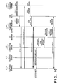
PSTN 103 is released (920) and abusy signal 921 sent from thePSTN 103 in response is converted to a busy signal 922 in accordance with TCP/IP by the PSTN-LAN telephone connection device 113-2. The busy signal 922 is sent to the LAN telephone terminal 111-i. Resource release processing is started with respect to the PSTN-LAN telephone connection device 113-2 by a disconnect operation performed at the LAN telephone terminal 111-i. Resource release reaches the PSTN-LAN telephone connection device 113-2 (923 - 925) while resource release processing is executed by theInternet connection device 112 andInternet 101 along the route. After thePSTN 103 is released,verification 927 is sent back and call processing is terminated. - Next, reference will be had to the sequence diagrams of Figs. 11 and 12 to describe operation in a case where a telephone call is made while changing a required QoS from the first priority to the next priority.
- In a manner similar to the case shown in Figs. 9 and 10, connection-
device search processing 1101 under the conditions of QoS-1 is started with respect to theLAN telephone server 110 by setting the destination ID and originating a call at LAN telephone terminal 111-i, and alist 1102 of connection device IDs is obtained. If it is assumed that only the PSTN-LAN telephone connection device 113-2 connected via theInternet 101 has been selected from the connection device ID list in a manner similar to that shown in Figs. 9 and 10, resource acquisition processing is executed successively by theInternet connection device 112 and Internet 101 (1103, 1104). In a case where resources adequate enough to satisfy the required communications quality QoS-1 are difficult to reserve in theInternet 101, the latter sends back a refusal 1105. The refusal 1105 arrives at the LAN telephone terminal 111-i as refusal 1106 via theInternet connection device 112. Upon receiving the refusal 1106, the LAN telephone terminal 111-i refers to the QoS list of thecommunications data flow 702 and reads out the QoS having the next highest priority. Connection-device search processing 1107 is executed under QoS-2 through a procedure similar to that in the case of QoS-1, anID list 1108 of connection devices is acquired and aresource acquisition operation 1109 is performed with respect to the PSTN-LAN telephone connection device 113-1 selected as the device that satisfies QoS-2. The PSTN-LAN telephone connection device 113-1 sends anoutgoing call signal 1110 to thePSTN 103, acquires adial tone 1111 and sendspermission 1112 to the LAN telephone terminal 111-i. Thereafter, processing is executed through a procedure similar to that of 911 - 919 of Figs. 9 and 10 untilcall establishment 1121. In a case where a disconnect operation is performed first at LAN telephone terminal 111-i when thecall 1121 is completed, resource release processing is executed with respect to the PSTN-LAN telephone connection device 113-1, the resources of thePSTN 103 are released (1123) andverification 1125 is sent back. Further, owing to the release of resources of thePSTN 103, a busy signal 1124 is sent to the ordinary telephone terminal 120-i that engaged in the call and thePSTN 103 is released. - The operation of the LAN telephone terminal 111-i will be described with reference to the flowcharts shown in Figs. 13 to 19.
- In the processing executed by the LAN telephone terminal 111-i shown in Fig. 13, control proceeds to call destination ID setting processing (Fig. 14) (S1311) in response to detection of a call destination ID setting operation ("YES" at step S1301); control proceeds to QoS setting processing (Fig. 15) (S1321) in response to detection of a QoS setting operation ("YES" at step S1302); and control proceeds to call origination processing (Figs. 16A and 16B) (S1331) in response to detection of a call originating operation ("YES" at step S1303). If a flow selection operation is detected ("YES" at step S1304), a selection (S1341) of call data flow is made and control returns to LAN telephone terminal processing (S1305). If nothing is detected ("NO" at steps S1301 - S1304), then LAN telephone terminal processing is repeated (S1305).
- In call destination ID setting processing shown in Fig. 14, it is determined at the time of the call ID setting operation whether a call destination ID delivered is unauthorized as a call destination ID. If the ID is not unauthorized ("NO" at step S1401), call
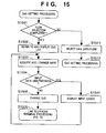
data flow 702 is generated (S1402) and control returns to LAN telephone terminal processing (Fig. 13). If the call destination ID is unauthorized ("YES" at step S1401), an ID setting value error is display (S1411) and control returns to LAN telephone terminal processing (Fig. 13) (S1412). - In QoS setting processing shown in Fig. 15, it is determined at the time of the QoS setting operation whether a call data flow has been selected. If one has not been selected ("NO" at step S1501), call data flow selection is performed (S1511) and control returns to QoS setting processing (S1512). When the call data flow is selected ("YES" at step S1501), a QoS list of the selected call data flow is referred to and displayed (S1502) and an input for adding to or changing the QoS list from the
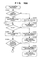
key input unit 305 is acquired (S1503). Next, it is determined whether the input data is unauthorized (S1504). If the input data is unauthorized ("YES" at step S1504), an input error display is presented (S1541) and control returns to the processing (S1503) for acquiring an addition/change input. If the input data is not unauthorized ("NO" at step S1504), then QoS change processing is executed with respect to the call data flow (S1505) and control returns to LAN telephone terminal processing (Fig. 13) (S1506). - In call origination processing shown in Figs. 16A and 16B, it is determined at the time of a call originating operation whether a call data flow has been selected (S1601). If a call data flow has not been selected ("NO" at step S1601), call data flow selection is performed (S1611) and control returns to call origination processing (S1619). If call data flow has been selected ("YES" at step S1601), the QoS list of this call data flow is referred to and the QoS of first priority is read out (S1602). If read-out of QoS is not possible ("NO" at step S1603), then the operator performs an operation to have the
LAN telephone server 110 search for connection devices that are capable of satisfying this QoS and a list of these connection devices is obtained from the LAN telephone server 110 (S1604). If the connection device ID list acquired from theLAN telephone server 110 is blank ("YES" at step S1605), an origination processing error display is presented (S1651) and control returns to LAN telephone terminal processing (Fig. 13) (S1659). If the connection device ID list is not blank ("NO" at step S1605), one connection device ID is selected (e.g., randomly) and is removed from the connection device ID list (S1606). If a connection device ID is obtained ("NO" at step S1607), then a resource acquisition operation capable of satisfying the selected QoS is started in regard to this connection device (S1608). If acquisition of resources is allowed ("YES" at step S1609), an operation for making a connection to the call destination ID obtained from the call data flow is started (S1610) and control proceeds to ringing-in-progress processing (S1690). If acquisition of resources has been refused ("NO" at step S1609), another connection device ID is selected from the connection device ID list again (S1606). If a connection device ID is not obtained ("YES" at step S1607), i.e., if resource acquisition has been refused with respect to the entire connection device ID list, the QoS having the next highest priority is read out of the QoS list (S1671) and the search for a connection device is started again (S1604). If a QoS having this next highest priority does not exist ("YES" at step S1603), a call origination processing error display is presented (S1631) and control returns to LAN telephone terminal processing (Fig. 13) (S1639). - In the ringing-in-progress processing shown in Fig. 17, control proceeds to disconnect processing (Fig. 19) (S1711) if a disconnect operation is sensed ("YES" at step S1701). In an answer is received ("YES" at step S1702), control proceeds to connection-in-progress processing (Fig. 18) (S1721). If a disconnect operation is not sensed and an answer is not received ("NO" at steps S1701, S1702), then ringing-in-progress processing is repeated (S1703).
- In connection-in-progress processing illustrated in Fig. 18, control proceeds to disconnect processing (Fig. 19) (S1811) if a disconnect operation is sensed ("YES" at step S1801). If a disconnect operation is not sensed ("NO" at step S1801), then connection-in-progress processing is repeated (S1802).
- In disconnect processing shown in Fig. 19, a resource release operation is performed with respect to the connection device currently connected (S1901), verification is received ("YES" at step 1903) and control returns to LAN telephone terminal processing (Fig. 13) (S1904). If verification is not received ("NO" at step S1903), a disconnect processing error is displayed (S1931) and control returns to LAN telephone terminal processing (Fig. 13) (S1904).
- The operation of the
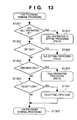
LAN telephone server 110 will now be described with reference to the flowcharts of Fig. 20 and 21. - In the LAN telephone server processing shown in Fig. 20, control proceeds to connection device search processing (Fig. 21) ("YES" at step S2011) if a connection device search operation is sensed. If this operation is not sensed ("NO" at step S2001), then LAN telephone server processing is repeated (S2002).
- In connection device search processing illustrated in Fig. 21, first a retrieved connection device ID list, which is the result of a search, is initialized (S2101) and a connection device ID is acquired from a self-managed connection device ID (S2102). When a connection device ID is acquired ("NO" at step S2103), reference is made to the assured QoS of this connection device (S2104). In a case where this assured QoS satisfies the QoS specified by the
LAN telephone terminal 111 when processing is started ("YES" at step S2105), i.e., in a case where the assured values of theaverage bit rate 821 andmaximum bit rate 822 exceed required values from theLAN telephone terminal 111 and the assured values of theaverage delay time 823,maximum delay time 824 andpacket loss rate 825 fall below the required values from theLAN telephone terminal 111, an addition is made to the connection device ID list that is the result of the search (S2151). If the requirement is not satisfied ("NO" at step S2105), then the next connection device ID is acquired (S2102). In a case where connection device IDs capable of being acquired are no longer available ("YES" at step S2103), the retrieved connection device ID list is posted to theLAN telephone terminal 111 that requested the connection device search (S2131) and control returns to LAN telephone server processing (Fig. 20) (S2139). - Next, the operation of the PSTN-LAN
telephone connection device 113 will be described with reference to the flowcharts of Figs. 22 to 25. - In the processing performed by the PSTN-LAN telephone connection device shown in Fig. 22, control proceeds to PSTN resource acquisition processing (Fig. 23) (S2219) if a resource acquisition operation performed at the
LAN telephone terminal 111 is sensed ("YES" at step S2201); to PSTN connect processing (Fig. 24) (S2229) if a connection operation performed at theLAN telephone terminal 111 is sensed ("YES" at step S2202); and to PSTN resource release processing (Fig. 25) (S2239) if a resource release operation performed at theLAN telephone terminal 111 is sensed ("YES" at step S2203). Otherwise ("NO" at steps S2201 - S2203), processing executed by the PSTN-LAN telephone connection device is repeated (S2209). - In the PSTN resource acquisition processing shown in Fig. 23, an idle outside line is selected (S2301) from the PSTN connection status at 742 in Fig. 7 holding information such as whether the aforementioned accommodated line is in use. If an idle outside line is obtained ("NO" at step S2302), an outgoing call signal is sent to this outside line (S2303). If a dial tone obtained from a network is sensed in response to the outgoing call signal ("YES" at step S2304), permission is sent back to the LAN telephone terminal 111 (S2305) and control returns to the processing (Fig. 22) performed by the PSTN-LAN telephone connection device (S2309). If a dial done cannot be sensed ("NO" at step S2304), another idle outside line is selected again (S2301) and similar processing is executed. If selectable idle outside lines are no longer available ("YES" at step S2302), refusal is sent back to the LAN telephone terminal 111 (S2321) and control returns to the processing (Fig. 22) performed by the PSTN-LAN telephone connection device (S2329).
- In PSTN connect processing shown in Fig. 24, first it is determined whether resources have been reserved, i.e., whether an outside line has been acquired and a call originated (S2401). If resources have not be reserved ("NO" at step S2401), control returns to the processing (Fig. 22) performed by the PSTN-LAN telephone connection device (S419). If resources have been reserved ("YES" at step S2401), a dialing signal based upon a call destination ID obtained from the
LAN telephone terminal 111 at the time of processing start-up is sent (S2402) and an answer signal from the other party's telephone terminal is awaited ("NO" at step S2403). If an answer signal is received ("YES" at step S2403), an answer is sent back to the LAN telephone terminal 111 (S2404) and control returns to the processing (Fig. 22) performed by the PSTN-LAN telephone connection device (S2409). In a case where resource release processing has been started up in a waiting state which lasts until the answer signal is received, control returns to the PSTN resource release processing of Fig. 25, though this is not illustrated - In the PSTN resource release processing shown in Fig. 25, first it is determined whether resources have been reserved (S2501) in a manner similar to that of the PSTN connect processing of Fig. 24. If resources have not been reserved ("NO" at step S2501), then control returns to the processing (Fig. 22) performed by the PSTN-LAN telephone connection device (S2519). If resources have been reserved ("YES" at step S2501), then the network (PSTN 103) is released (S2502), verification is sent back to the LAN telephone terminal 111 (S2503) and control returns to the processing (Fig. 22) performed by the PSTN-LAN telephone connection device (S2509).
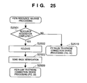
- Thus, in accordance with this embodiment, communications quality required for communications, such as average bit rate, maximum bit rate, average delay time, maximum delay time and packet loss rate can be selected flexibly in dependence upon the status of the network.
- Further, selection of communication quality is performed automatically. This makes it possible to perform communication at optimum communications quality in a manner transparent to the user.
- Further, the user is capable of setting a plurality of communications qualities having different priorities.
- When communication is carried out via networks the communications schemes whereof differ from one another, particularly networks such a LAN, the Internet and a PSTN, optimum communication quality can be selected. In addition, the optimum network can be selected automatically.
- Next, there will be described a second embodiment in which the
QoS list 801 of Fig. 8 according to the first embodiment is changed to aQoS list 803 of Fig. 26 and a cost calculation table 600 shown in Fig. 6 is added on. - The cost calculation table 600 shown in Fig. 6 is capable of being referred to by the
LAN telephone server 110 and retains, in a table format, telephone call charges based upon the PSTN-LAN telephone connection devices 113-1 to 113-N, which are managed by theLAN telephone server 110, and call destination ID areas (toll numbers in this case). - The
QoS list 803 of Fig. 26 is the result of adding, onto theQoS list 801 of Fig. 8, anupper limit 841 on cost permitted in order to obtain the particular QoS. - The operation involved will now be described. The basic operation, which is similar to that of the first embodiment, is to change the decision (S2105), as to whether the required QoS is satisfied or not, in the connection device search processing (Fig. 21) of the
LAN telephone server 110 in such a manner that use is made of the cost calculation table 600 andQoS list 803. That is, in the processing (S2105) for judging whether the requirement is satisfied or not, the desired unit charge is read out of the cost calculation table 600 and a decision is rendered to the effect that the required QoS is satisfied if two conditions are met, namely that the value of the desired unit charge is less than theupper limit 841 on cost and that the conditions set forth in the first embodiment are satisfied. - In accordance with this embodiment, it is possible to select the optimum communications quality that takes communications cost into consideration as one element of communications quality.
- It should be noted that an arrangement may be adopted in which the functions of the first and second embodiments are supplemented by reporting to the user the communications quality that has been automatically selected. More specifically, the content of the automatically selected communications quality may be displayed on the display unit of a LAN telephone terminal so that the user may refer to it when setting the QoS.
- Further, in order to make the communications quality reported to the user easier to understand, QoS-1 to QoS-N of Figs. 8 and 26 can be associated with
levels 1 to N in the order of priority and the level that corresponds to the automatically selected QoS can be displayed. - Thus, in accordance with the present invention, as described above, communications quality required for communications, such as average bit rate, maximum bit rate, average delay time, maximum delay time and packet loss rate can be selected flexibly and optimally in dependence upon the status of the network.
- Further, the selection of communications quality is performed automatically. This makes it possible to perform communication at optimum communications quality in a manner transparent to the user.
- Further, the user is capable of setting a plurality of communications qualities having different priorities.
- When communication is carried out via networks the communications schemes whereof differ from one another, particularly networks such a LAN, the Internet and a PSTN, optimum communication quality can be selected. In addition, the optimum network can be selected automatically.
- As many apparently widely different embodiments of the present invention can be made without departing from the spirit and scope thereof, it is to be understood that the invention is not limited to the specific embodiments thereof except as defined in the appended claims.
Claims (60)
- A communications system having a plurality of connection devices for connection to a plurality of communications networks, a communications apparatus capable of communicating with the connection devices, and a management apparatus for performing management relating at least to communication by the communications apparatus, said system comprising:storage means for storing a plurality of communications qualities necessary for communications by the communications apparatus;selection means for selecting at least one connection device based upon the plurality of communications qualities stored in said storage means; andcommunications resources acquisition means for acquiring communications resources in order to perform communication via the connection device selected by said selection means;wherein said selection means is possessed by said management apparatus.
- The system according to claim 1, wherein the communications qualities includes a plurality of parameters, and said storage means stores a plurality of communications qualities which include the plurality of parameters.
- The system according to claim 1 or 2, wherein the communications qualities include a least one of average bit rate, maximum bit rate, average delay time, maximum delay time, packet loss rate and upper limit on communications cost, which are required for communications.
- The system according to any one of claims 1 to 3, wherein the plurality of communications networks include at least one of a local area network, a public network and the Internet.
- The system according to any one of claims 1 to 3, wherein one of the plurality of communications networks is the Internet.
- The system according to any one of claims 1 to 5, wherein the communications qualities are capable of being selected beforehand by an operator.
- The system according to any one of claims 1 to 6, wherein said storage means is possessed by said communications apparatus.
- The system according to any one of claims 1 to 7, wherein said communications resources acquisition means is possessed by said connection devices.
- The system according to any one of claims 1 to 8, wherein a plurality of communications qualities are stored in said storage means in a formed ranked by priority.
- The system according to claim 9, wherein in a case where communication cannot be performed via a first connection device that has been selected based upon a communications quality having a first priority, said selection means selects a second connection device based upon a communications quality having a second priority.
- The system according to claim 10, wherein the case where communication cannot be performed via said first connection device is a case where communications resources cannot be acquired by said communications resources acquisition means.
- The system according to any one of claims 1 to 11, further comprising notification means for posting information that is based upon a communications quality assured by the connection device that has been selected.
- A management apparatus in a communications system having a plurality of connection devices for connection to a plurality of communications networks, a communications apparatus capable of communicating with the connection devices, and the management apparatus, which is for performing management relating at least to communication by the communications apparatus, said management apparatus comprising:storage means for storing information relating to the plurality of connection devices;receiving means for receiving, from the communications apparatus, information indicating communications quality necessary for communications; andselection means for selecting at least one connection device from said plurality of connection devices based upon the information indicating the communications quality received by said receiving means and the information relating to the plurality of connection devices stored in said storage means.
- The apparatus according to claim 13, wherein the communications quality received by said receiving means includes a plurality of parameters.
- The apparatus according to claim 13 or 14, wherein the communications quality received by said receiving means include a least one of average bit rate, maximum bit rate, average delay time, maximum delay time, packet loss rate and upper limit on communications cost, which are required for communications.
- The apparatus according to any one of claims 13 to 15, wherein the plurality of communications networks include at least one of a local area network, a public network and the Internet.
- The apparatus according to any one of claims 13 to 15, wherein one of the plurality of communications networks is the Internet.
- The apparatus according to any one of claims 13 to 17, wherein in a case where communication cannot be performed via a first connection device that has been selected based upon a first communications quality, said selection means selects a second connection device based upon a second communications quality.
- The apparatus according to claim 18, wherein the case where communication cannot be performed via said first connection device is a case where communications resources cannot be acquired by said first connection device.
- A communications apparatus in a communications system having a plurality of connection devices for connection to a plurality of communications networks, the communications apparatus, which is capable of communicating with the connection devices, and a management apparatus for performing management relating at least to communication by the communications apparatus, said communications apparatus comprising:storage means for storing a plurality of communications qualities necessary for communications;requesting means for requesting said management apparatus to select at least one connection device based upon the plurality of communications qualities stored in said storage means; andcommunicating means for communicating via the connection device selected by said management apparatus based upon the request by said requesting means.
- The apparatus according to claim 20, wherein said communicating means performs communication using communications resources acquired by said connection device.
- The apparatus according to claim 20 or 21, wherein the communications qualities includes a plurality of parameters, and said storage means stores a plurality of communications qualities which include the plurality of parameters.
- The apparatus according to any one of claims 20 to 22, wherein the communications qualities include a least one of average bit rate, maximum bit rate, average delay time, maximum delay time, packet loss rate and upper limit on communications cost, which are required for communications.
- The apparatus according to any one of claims 20 to 23, wherein the plurality of communications networks include at least one of a local area network, a public network and the Internet.
- The apparatus according to any one of claims 20 to 23, wherein one of the plurality of communications networks is the Internet.
- The apparatus according to any one of claims 20 to 25, wherein the communications quality is capable of being set beforehand by an operator.
- The apparatus according to any one of claims 20 to 26, wherein the plurality of communications qualities stored in said storage means are ranked by priority.
- The apparatus according to claim 27, wherein in a case where communication cannot be performed via a first connection device that has been selected based upon a communications quality having a first priority, said requesting means requests said management apparatus to select a second connection device based upon a communications quality having a second priority.
- The apparatus according to claim 28, wherein the case where communication cannot be performed via said first connection device is a case where communications resources cannot be acquired by said first connection device.
- The apparatus according to any one of claims 20 to 29, further comprising notification means for posting information that is based upon a communications quality assured by the connection device that has been selected.
- A method of controlling a communications system having a plurality of connection devices for connection to a plurality of communications networks, a communications apparatus capable of communicating with the connection devices, and a management apparatus for performing management relating at least to communication by the communications apparatus, said method comprising:a storage step of storing a plurality of communications qualities necessary for communications by the communications apparatus;a selection step of selecting at least one connection device based upon the plurality of communications qualities stored at said storage step; anda communications resources acquisition step of acquiring communications resources in order to perform communication via the connection device selected at said selection step;wherein said selection step is implemented by said management apparatus.
- The method according to claim 31, wherein the communications qualities includes a plurality of parameters, and said storage step stores a plurality of communications qualities which include the plurality of parameters.
- The method according to claim 31 or 32, wherein the communications qualities include a least one of average bit rate, maximum bit rate, average delay time, maximum delay time, packet loss rate and upper limit on communications cost, which are required for communications.
- The method according to any one of claims 31 to 33, wherein the plurality of communications networks include at least one of a local area network, a public network and the Internet.
- The method according to any one of claims 31 to 33, wherein one of the plurality of communications networks is the Internet.
- The method according to any one of claims 31 to 35, wherein the communications qualities are capable of being selected beforehand by an operator.
- The method according to any one of claims 31 to 36, wherein said storage step is implemented by said communications apparatus.
- The method according to any one of claims 31 to 37, wherein said communications resources acquisition step is implemented by said connection devices
- The method according to any one of claims 31 to 38, wherein a plurality of communications qualities stored at said storage step are ranked by priority.
- The method according to claim 39, wherein in a case where communication cannot be performed via a first connection device that has been selected based upon a communications quality having a first priority, said selection step selects a second connection device based upon a communications quality having a second priority.
- The method according to claim 40, wherein the case where communication cannot be performed via said first connection device is a case where communications resources cannot be acquired at said communications resources acquisition step.
- The method according to any one of claims 31 to 41, further comprising a notification step of posting information that is based upon a communications quality assured by the connection device that has been selected.
- A method of controlling a management apparatus in a communications system having a plurality of connection devices for connection to a plurality of communications networks, a communications apparatus capable of communicating with the connection devices, and the management apparatus, which is for performing management relating at least to communication by the communications apparatus, said method comprising:a storage step of storing information relating to the plurality of connection devices;a receiving step of receiving, from the communications apparatus, information indicating communications quality necessary for communications; anda selection step of selecting at least one connection device from said plurality of connection devices based upon the information indicating the communications quality received at said receiving step and the information relating to the plurality of connection devices stored at said storage step.
- The method according to claim 43, wherein the communications quality received at said receiving step includes a plurality of parameters.
- The method according to claim 43 or 44, wherein the communications quality received at said receiving step include a least one of average bit rate, maximum bit rate, average delay time, maximum delay time, packet loss rate and upper limit on communications cost, which are required for communications.
- The method according to any one of claims 43 to 45, wherein the plurality of communications networks include at least one of a local area network, a public network and the Internet.
- The method according to any one of claims 43 to 45, wherein one of the plurality of communications networks is the Internet.
- The method according to any one of claims 43 to 47, wherein in a case where communication cannot be performed via a first connection device that has been selected based upon a first communications quality, said selection means selects a second connection device based upon a second communications quality.
- The method according to claim 48, wherein the case where communication cannot be performed via said first connection device is a case where communications resources cannot be acquired at said first connection device.
- A method of controlling a communications apparatus in a communications system having a plurality of connection devices for connection to a plurality of communications networks, the communications apparatus, which is capable of communicating with the connection devices, and a management apparatus for performing management relating at least to communication by the communications apparatus, said method comprising:a storage step of storing a plurality of communications qualities necessary for communications;a requesting step of requesting said management apparatus to select at least one connection device based upon the plurality of communications qualities stored at said storage step; anda communicating step of communicating via the connection device selected by said management apparatus based upon the request made at said requesting step.
- The method according to claim 50, wherein said communicating step performs communication using communications resources acquired by said connection device.
- The method according to claim 50 or 51, wherein the communications qualities includes a plurality of parameters, and said storage step stores a plurality of communications qualities which include the plurality of parameters.
- The method according to any one of claims 50 to 52, wherein the communications qualities include a least one of average bit rate, maximum bit rate, average delay time, maximum delay time, packet loss rate and upper limit on communications cost, which are required for communications.
- The method according to any one of claims 50 to 53, wherein the plurality of communications networks include at least one of a local area network, a public network and the Internet.
- The method according to any one of claims 50 to 53, wherein one of the plurality of communications networks is the Internet.
- The method according to any one of claims 50 to 55, wherein the communications quality is capable of being set beforehand by an operator.
- The method according to any one of claims 50 to 56, wherein the plurality of communications qualities stored at said storage step are ranked by priority.
- The method according to claim 57, wherein in a case where communication cannot be performed via a first connection device that has been selected based upon a communications quality having a first priority, said requesting step requests said management apparatus to select a second connection device based upon a communications quality having a second priority.
- The method according to claim 58, wherein the case where communication cannot be performed via said first connection device is a case where communications resources cannot be acquired by said first connection device.
- The method according to any one of claims 50 to 59, further comprising a notification step of posting information that is based upon a communications quality assured by the connection device that has been selected.
Applications Claiming Priority (2)
| Application Number | Priority Date | Filing Date | Title |
|---|---|---|---|
| JP03592798A JP4266403B2 (en) | 1998-02-18 | 1998-02-18 | Communication system and control method thereof |
| JP3592798 | 1998-02-18 |
Publications (2)
| Publication Number | Publication Date |
|---|---|
| EP0949842A2 true EP0949842A2 (en) | 1999-10-13 |
| EP0949842A3 EP0949842A3 (en) | 2004-08-25 |
Family
ID=12455678
Family Applications (1)
| Application Number | Title | Priority Date | Filing Date |
|---|---|---|---|
| EP99400378A Withdrawn EP0949842A3 (en) | 1998-02-18 | 1999-02-17 | Communications system and method of controlling same |
Country Status (4)
| Country | Link |
|---|---|
| US (1) | US6570879B1 (en) |
| EP (1) | EP0949842A3 (en) |
| JP (1) | JP4266403B2 (en) |
| CN (1) | CN100370792C (en) |
Cited By (1)
| Publication number | Priority date | Publication date | Assignee | Title |
|---|---|---|---|---|
| WO2007110090A1 (en) * | 2006-03-24 | 2007-10-04 | Telefonaktiebolaget Lm Ericsson (Publ) | Generic access performance abstraction for access selection |
Families Citing this family (9)
| Publication number | Priority date | Publication date | Assignee | Title |
|---|---|---|---|---|
| JP2001237897A (en) * | 2000-02-22 | 2001-08-31 | Nec Corp | Hybrid type telephony system |
| US7111163B1 (en) | 2000-07-10 | 2006-09-19 | Alterwan, Inc. | Wide area network using internet with quality of service |
| DE60119866T2 (en) * | 2000-09-27 | 2007-05-10 | International Business Machines Corp. | Switching device and method with separate output buffers |
| US7523203B1 (en) * | 2001-05-07 | 2009-04-21 | Cisco Technology, Inc. | Shared distribution media resources in a communication network |
| CN1172504C (en) * | 2001-09-29 | 2004-10-20 | 华为技术有限公司 | Method of creating charging identification in internet one number link you |
| US7286553B2 (en) * | 2001-12-04 | 2007-10-23 | Murata Kikai Kabushiki Kaisha | Communication device and method for controlling communication device |
| CN100559901C (en) * | 2002-02-15 | 2009-11-11 | 艾利森电话股份有限公司 | In communication network, set up method and node that priority connects |
| US7873743B2 (en) * | 2005-12-05 | 2011-01-18 | Sony Ericsson Mobile Communications Ab | Electronic apparatus with router device for managing connections |
| US8127011B2 (en) * | 2007-03-23 | 2012-02-28 | Telefonaktiebolaget L M Ericsson (Publ) | Network resource negotiation between a service provider network and an access network |
Citations (2)
| Publication number | Priority date | Publication date | Assignee | Title |
|---|---|---|---|---|
| US5610910A (en) * | 1995-08-17 | 1997-03-11 | Northern Telecom Limited | Access to telecommunications networks in multi-service environment |
| US5654957A (en) * | 1994-05-12 | 1997-08-05 | Hitachi, Ltd. | Packet communication system |
Family Cites Families (8)
| Publication number | Priority date | Publication date | Assignee | Title |
|---|---|---|---|---|
| JPH06276254A (en) * | 1993-03-17 | 1994-09-30 | Nippon Telegr & Teleph Corp <Ntt> | Communication control equipment |
| JPH07170288A (en) * | 1993-12-15 | 1995-07-04 | Hitachi Ltd | Voice communication system and voice communication method |
| IL115967A (en) * | 1995-11-12 | 1999-05-09 | Phonet Communication Ltd | Network based distributed pbx system |
| US5732078A (en) * | 1996-01-16 | 1998-03-24 | Bell Communications Research, Inc. | On-demand guaranteed bandwidth service for internet access points using supplemental user-allocatable bandwidth network |
| US6137792A (en) * | 1996-06-14 | 2000-10-24 | International Discount Telecommunications Corp. | Method and apparatus for enabling transmission of data packets over a bypass circuit-switched public telephone connection |
| US5970126A (en) * | 1996-08-09 | 1999-10-19 | International Business Machines Corporation | Communication method and system |
| US6064653A (en) * | 1997-01-07 | 2000-05-16 | Bell Atlantic Network Services, Inc. | Internetwork gateway to gateway alternative communication |
| US5898673A (en) * | 1997-02-12 | 1999-04-27 | Siemens Information And Communication Networks, Inc. | System and method for prevention of cell loss due to quality of service contracts in an ATM network |
-
1998
- 1998-02-18 JP JP03592798A patent/JP4266403B2/en not_active Expired - Fee Related
-
1999
- 1999-02-15 CN CNB991022726A patent/CN100370792C/en not_active Expired - Fee Related
- 1999-02-16 US US09/250,082 patent/US6570879B1/en not_active Expired - Lifetime
- 1999-02-17 EP EP99400378A patent/EP0949842A3/en not_active Withdrawn
Patent Citations (2)
| Publication number | Priority date | Publication date | Assignee | Title |
|---|---|---|---|---|
| US5654957A (en) * | 1994-05-12 | 1997-08-05 | Hitachi, Ltd. | Packet communication system |
| US5610910A (en) * | 1995-08-17 | 1997-03-11 | Northern Telecom Limited | Access to telecommunications networks in multi-service environment |
Non-Patent Citations (5)
| Title |
|---|
| HOUGHTON T F ET AL: "A PACKET TELEPHONY GATEWAY FOR PUBLIC NETWORK OPERATORS" ISS '97. WORLD TELECOMMUNICATIONS CONGRESS. (INTERNATIONAL SWITCHING SYMPOSIUM). GLOBAL NETWORK EVOLUTION: CONVERGENCE OR COLLISION? TORONTO, SEPT. 21 - 26, 1997, ISS. WORLD TELECOMMUNICATIONS CONGRESS. (INTERNATIONAL SWITCHING SYMPOSIUM), TORONTO, P, vol. 2, 21 September 1997 (1997-09-21), pages 35-44, XP000704453 * |
| PATENT ABSTRACTS OF JAPAN vol. 018, no. 687 (E-1651), 26 December 1994 (1994-12-26) & JP 06 276254 A (NIPPON TELEGR & TELEPH CORP), 30 September 1994 (1994-09-30) * |
| ROUSSEL A-M: "A CARD FOR ALL-IN-ONE WAN ACCESS" DATA COMMUNICATIONS, MCGRAW HILL. NEW YORK, US, vol. 23, no. 1, 1994, pages 70-71, XP000418307 ISSN: 0363-6399 * |
| TAYLOR K: "REMOTE SITES: IN FROM THE COLD" DATA COMMUNICATIONS, MCGRAW HILL. NEW YORK, US, vol. 25, no. 5, 1 April 1996 (1996-04-01), page 40,42 XP000582658 ISSN: 0363-6399 * |
| THOM G A: "H. 323: THE MULTIMEDIA COMMUNICATIONS STANDARD FOR LOCAL AREA NETWORKS" IEEE COMMUNICATIONS MAGAZINE, IEEE SERVICE CENTER. PISCATAWAY, N.J, US, vol. 34, no. 12, 1 December 1996 (1996-12-01), pages 52-56, XP000636454 ISSN: 0163-6804 * |
Cited By (3)
| Publication number | Priority date | Publication date | Assignee | Title |
|---|---|---|---|---|
| WO2007110090A1 (en) * | 2006-03-24 | 2007-10-04 | Telefonaktiebolaget Lm Ericsson (Publ) | Generic access performance abstraction for access selection |
| KR101234391B1 (en) | 2006-03-24 | 2013-02-18 | 텔레폰악티에볼라겟엘엠에릭슨(펍) | Generic access performance abstraction for access selection |
| US8867567B2 (en) | 2006-03-24 | 2014-10-21 | Telefonaktiebolaget L M Ericsson (Publ) | Generic access performance abstraction for access selection |
Also Published As
| Publication number | Publication date |
|---|---|
| EP0949842A3 (en) | 2004-08-25 |
| CN1238624A (en) | 1999-12-15 |
| US6570879B1 (en) | 2003-05-27 |
| JP4266403B2 (en) | 2009-05-20 |
| CN100370792C (en) | 2008-02-20 |
| JPH11234400A (en) | 1999-08-27 |
Similar Documents
| Publication | Publication Date | Title |
|---|---|---|
| US6657957B1 (en) | Method and apparatus for dynamically controlling the admission of calls to a network | |
| EP0873637B1 (en) | Method and apparatus for implementing a computer network/internet telephone system | |
| US7738642B2 (en) | Reverse charging system, reverse-charging service control apparatus, call agent and reverse charging method | |
| JPH11225206A (en) | System and method to set up call connection | |
| GB2346503A (en) | System and method for securing available communications network resources | |
| JP2000504183A (en) | Complex network for real-time telephone-to-telephone voice communication | |
| RU2218673C2 (en) | Method for establishing connections in communication network | |
| KR100512222B1 (en) | Optimizing voice-over-ip priority and bandwidth requirements | |
| EP0949842A2 (en) | Communications system and method of controlling same | |
| US6731740B1 (en) | Method for preventing overload condition in a circuit switched arrangement | |
| KR100248410B1 (en) | Call control method using atc call gap | |
| US7286654B1 (en) | Method for preventing overload condition in a circuit switched arrangement | |
| US7548550B1 (en) | Intelligent peripheral concentrator | |
| US6826273B1 (en) | Method for preventing overload condition in a circuit switched arrangement | |
| JP3782644B2 (en) | Communications system | |
| EP0861006A1 (en) | A service of a telecommunication system and service device realising such a service | |
| EP0445803A2 (en) | Method and apparatus for data transfer and circuit setting for communication network system | |
| US6370243B2 (en) | Method for transmitting data traffic in a telecommunications system | |
| US5761274A (en) | Method for regurating call congestion and ISDN exchanger for performing the same | |
| JP3441843B2 (en) | Multi-user connection between stations | |
| US7068662B2 (en) | Establishing a broadband connection that saves resources and satisfies billing conditions | |
| US7099329B1 (en) | Method for preventing overload condition in a circuit switched arrangement | |
| RU2359428C2 (en) | Method for transfer of mm4 interface messages in system of multimedia messages | |
| JP2000156747A (en) | Method for setting charge-optimized communication connection, server and communication node | |
| US6987848B1 (en) | Method for preventing overload condition in a circuit switched arrangement |
Legal Events
| Date | Code | Title | Description |
|---|---|---|---|
| PUAI | Public reference made under article 153(3) epc to a published international application that has entered the european phase |
Free format text: ORIGINAL CODE: 0009012 |
|
| AK | Designated contracting states |
Kind code of ref document: A2 Designated state(s): AT BE CH CY DE DK ES FI FR GB GR IE IT LI LU MC NL PT SE |
|
| AX | Request for extension of the european patent |
Free format text: AL;LT;LV;MK;RO;SI |
|
| PUAL | Search report despatched |
Free format text: ORIGINAL CODE: 0009013 |
|
| AK | Designated contracting states |
Kind code of ref document: A3 Designated state(s): AT BE CH CY DE DK ES FI FR GB GR IE IT LI LU MC NL PT SE |
|
| AX | Request for extension of the european patent |
Extension state: AL LT LV MK RO SI |
|
| RIC1 | Information provided on ipc code assigned before grant |
Ipc: 7H 04L 12/66 B Ipc: 7H 04L 12/24 B Ipc: 7H 04Q 11/04 B Ipc: 7H 04L 12/28 A |
|
| 17P | Request for examination filed |
Effective date: 20041231 |
|
| AKX | Designation fees paid |
Designated state(s): DE FR GB IT |
|
| 17Q | First examination report despatched |
Effective date: 20050617 |
|
| RBV | Designated contracting states (corrected) |
Designated state(s): DE FR GB IT |
|
| STAA | Information on the status of an ep patent application or granted ep patent |
Free format text: STATUS: THE APPLICATION IS DEEMED TO BE WITHDRAWN |
|
| 18D | Application deemed to be withdrawn |
Effective date: 20140624 |