EP0952552A2 - Method for generating 2-D images from 3-D video data - Google Patents
Method for generating 2-D images from 3-D video data Download PDFInfo
- Publication number
- EP0952552A2 EP0952552A2 EP99302995A EP99302995A EP0952552A2 EP 0952552 A2 EP0952552 A2 EP 0952552A2 EP 99302995 A EP99302995 A EP 99302995A EP 99302995 A EP99302995 A EP 99302995A EP 0952552 A2 EP0952552 A2 EP 0952552A2
- Authority
- EP
- European Patent Office
- Prior art keywords
- image
- recited
- video sequence
- motion parameters
- scene
- Prior art date
- Legal status (The legal status is an assumption and is not a legal conclusion. Google has not performed a legal analysis and makes no representation as to the accuracy of the status listed.)
- Withdrawn
Links
- 238000000034 method Methods 0.000 title claims abstract description 44
- 239000011159 matrix material Substances 0.000 claims abstract description 19
- 239000013598 vector Substances 0.000 claims abstract description 14
- 238000013519 translation Methods 0.000 claims abstract description 9
- 238000007781 pre-processing Methods 0.000 claims description 9
- 230000011218 segmentation Effects 0.000 claims description 7
- 238000007670 refining Methods 0.000 claims description 4
- 230000008569 process Effects 0.000 description 13
- 101000911753 Homo sapiens Protein FAM107B Proteins 0.000 description 8
- 102100026983 Protein FAM107B Human genes 0.000 description 8
- 238000013459 approach Methods 0.000 description 8
- 238000010586 diagram Methods 0.000 description 7
- 230000008859 change Effects 0.000 description 4
- 238000012545 processing Methods 0.000 description 4
- 230000003068 static effect Effects 0.000 description 4
- 230000002123 temporal effect Effects 0.000 description 4
- 239000000463 material Substances 0.000 description 3
- 238000001514 detection method Methods 0.000 description 2
- 230000006870 function Effects 0.000 description 2
- 238000013507 mapping Methods 0.000 description 2
- 230000009466 transformation Effects 0.000 description 2
- 230000001174 ascending effect Effects 0.000 description 1
- 230000002457 bidirectional effect Effects 0.000 description 1
- 230000006835 compression Effects 0.000 description 1
- 238000007906 compression Methods 0.000 description 1
- 230000001955 cumulated effect Effects 0.000 description 1
- 230000003247 decreasing effect Effects 0.000 description 1
- 230000000694 effects Effects 0.000 description 1
- 238000001914 filtration Methods 0.000 description 1
- 230000010354 integration Effects 0.000 description 1
- 230000003993 interaction Effects 0.000 description 1
- 238000010606 normalization Methods 0.000 description 1
- 230000001902 propagating effect Effects 0.000 description 1
- 230000000717 retained effect Effects 0.000 description 1
Images


Classifications
-
- G—PHYSICS
- G06—COMPUTING; CALCULATING OR COUNTING
- G06T—IMAGE DATA PROCESSING OR GENERATION, IN GENERAL
- G06T7/00—Image analysis
- G06T7/20—Analysis of motion
- G06T7/246—Analysis of motion using feature-based methods, e.g. the tracking of corners or segments
-
- G—PHYSICS
- G06—COMPUTING; CALCULATING OR COUNTING
- G06T—IMAGE DATA PROCESSING OR GENERATION, IN GENERAL
- G06T7/00—Image analysis
- G06T7/50—Depth or shape recovery
- G06T7/55—Depth or shape recovery from multiple images
- G06T7/579—Depth or shape recovery from multiple images from motion
-
- G—PHYSICS
- G06—COMPUTING; CALCULATING OR COUNTING
- G06T—IMAGE DATA PROCESSING OR GENERATION, IN GENERAL
- G06T2200/00—Indexing scheme for image data processing or generation, in general
- G06T2200/32—Indexing scheme for image data processing or generation, in general involving image mosaicing
-
- G—PHYSICS
- G06—COMPUTING; CALCULATING OR COUNTING
- G06T—IMAGE DATA PROCESSING OR GENERATION, IN GENERAL
- G06T2207/00—Indexing scheme for image analysis or image enhancement
- G06T2207/10—Image acquisition modality
- G06T2207/10016—Video; Image sequence
-
- Y—GENERAL TAGGING OF NEW TECHNOLOGICAL DEVELOPMENTS; GENERAL TAGGING OF CROSS-SECTIONAL TECHNOLOGIES SPANNING OVER SEVERAL SECTIONS OF THE IPC; TECHNICAL SUBJECTS COVERED BY FORMER USPC CROSS-REFERENCE ART COLLECTIONS [XRACs] AND DIGESTS
- Y10—TECHNICAL SUBJECTS COVERED BY FORMER USPC
- Y10S—TECHNICAL SUBJECTS COVERED BY FORMER USPC CROSS-REFERENCE ART COLLECTIONS [XRACs] AND DIGESTS
- Y10S345/00—Computer graphics processing and selective visual display systems
- Y10S345/949—Animation processing method
- Y10S345/95—Sprite processing
Definitions
- the present invention relates to the processing of video sequences, and more particularly to 2-D extended image generation from 3-D data extracted from a video sequence of a natural three-dimensional scene as observed through a monocular moving camera.
- video sequences provide two-dimensional images of natural three-dimensional scenes as observed through a monocular moving camera.
- a graphics generator is required for building such objects or images, which objects or images are then projected onto a two-dimensional plane for viewing as part of the video sequence.
- Three-dimensional manipulation of the three-dimensional objects or images is performed by the graphics generator, but the results are seen as a two-dimensional object or image in the video sequence.
- What is desired is a method of generating 2-D extended images from 3-D data extracted from a two-dimensional video sequence.
- the present invention provides a method of generating 2-D extended images from 3-D data extracted from a video sequence representing a natural scene.
- image feature points are determined and subsequently tracked from frame to frame of the video sequence.
- structure-from-motion stage the image feature points are used to estimate three-dimensional object velocity and depth.
- depth and motion information are post-processed to generate a dense three-dimensional depth map.
- World surfaces, corresponding to extended surfaces, are composed by integrating the three-dimensional depth map information.
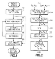
- Fig. 1 is a flow diagram view for the generation of 2-D extended images for an object from a video sequence representing a natural 3-D scene according to the present invention.
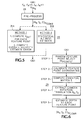
- Fig. 2 is a flow diagram view of a camera motion parameter estimator according to the present invention.
- Figs. 3A, 3B and 3C respectively are illustrations of an image in a scene shot from the video image sequence, a mask for the image defining the object, and a 2-D extended image for the defined object according to the present invention.
- Fig. 4 is a flow diagram view of a hierarchical matching scheme according to the present invention.
- Fig. 5 is a general flow diagram view of a structure-from-motion (SFM) algorithm according to the present invention.
- Fig. 6 is a flow diagram view of a pre-processing stage for the SFM algorithm of Fig. 5 according to the present invention.
- Figs. 7A, 7B and 7C respectively are illustrations of an image in a scene from a video sequence, a depth map for the image, and a segmentation mask for a foreground object in the image according to the present invention.
- Fig. 8 is a flow diagram view of a 2-D extended image generator according to the present invention.
- Fig. 9 is an illustration of the pasting of points of an image in a scene from a video sequence into a 2-D extended image according to the present invention.
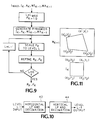
- Fig. 10 is a flow diagram view of a filter for producing diadic pyramids according to the present invention.
- Fig. 11 is an illustrative view of the mapping of points from an image from the video sequence into the 2-D extended image according to the present invention.
- the present invention describes the generation of a 2-D extended image, referred to as a world image, sprite or wall paper, from a video of a natural 3-D scene as observed through a monocular moving camera.
- This 2-D extended image represents in some way, usually with some loss, the information contained in the video representing a natural 3-D scene. Also the original video, with some loss in quality, may be synthesized from this 2-D extended image.
- the method described below is divided into two parts: 3-D camera parameter estimation and 2-D extended image generation.
- a temporal sequence of raw video images representing a natural 3-D scene projected onto the moving camera is input to the system.
- a scene cut detector 12 identifies the temporal boundaries within the scene that make up an input video sequence, and the sequence of images that lies within such temporal boundaries constitute one scene shot.
- the images for the detected scene shot are input to a pre-segmentor 14 where objects are identified based upon various characteristics, such as color, shape and velocity, by using manual, semi-automatic or automatic processes.
- the pre-segmentation process also selects and tracks features on the objects from image to image within the scene shot.
- a tennis player may be identified as an object and the player's shoes or tennis racquet may be selected as features.
- the information from the pre-segmentor 14 is input to a 3-D camera parameter estimator 16 to estimate camera parameters, namely (i) the 3-D velocity of the objects in the scene and of the camera relative to some origin in 3-D space, and (ii) the depth of the objects from the camera.
- This depth and motion information is processed to generate a dense 3-D depth map for each object, as is described below.
- a decision block 18 determines the "flatness" of the object, and also provides feedback to the pre-segmentor 14 to assist in separating objects on the basis of depth layers.
- the depth map information and the scene shot images are input to a 2-D extended image generator 20 to produce a 2-D extended image for each object in the scene shot.
- the 3-D camera parameter estimator 16 uses a structure-from-motion (SFM) algorithm to estimate camera parameters from the pre-segmented video, as described in greater detail below.
- SFM structure-from-motion
- SFM is typically used to estimate the 3-D velocities and depths of points of rigid opaque objects.
- SFM is used for two purposes: first to estimate the 3-D parameters of independently moving objects, called foreground objects, such as a car moving along a street in a video clip; and second to estimate the 3-D parameters of the scene shot's background, called background object, such as the audience in the tennis match video clip.
- the background object represents that part of the scene shot that is static in the world, i.e., has a zero velocity with respect to some point in 3-D space in a world coordinate system, while the camera and foreground objects may be in motion with respect to the same point.
- the background object may appear to be in motion because of the camera movement.
- the video clip therefore records the velocity of the background object with respect to the set of coordinate axes located at the focal plane of the camera.
- This apparent 3-D velocity of the background object is opposite in sign but identical in magnitude to the velocity of the camera with respect to the fixed point in 3-D space.
- the 3-D trajectory and orientation of the camera are determined with respect to the world coordinate system.
- SFM currently requires that foreground objects be pre-segmented from the background object, and that feature points on the different objects be chosen manually. In this application feature points on the objects are automatically selected and tracked while these objects are still assumed to be pre-segmented.
- SFM when applied to the background object, provides the 3-D camera velocity parameters and the depth from the camera of feature points in the background object. Using the camera velocity parameters, the depth is estimated at the feature points and the resulting values are interpolated/extrapolated to generate a depth value for each image pixel in the scene shot to provide a dense depth map.
- the 2-D extended image generator 20 combines the results of the depth map compositing, using a planar perspective projection (PPP) model to generate the image.
- the PPP model has nine parameters, which enables the estimation or prediction of the 2-D extended image given any single image, i.e., current frame or snapshot of the scene shot.
- the PPP model parameters are also used to estimate or predict a current frame from the extended image.
- the depth map which is generated for pairs of successive images, is combined with the PPP model parameters associated with the first image in the pair to generate approximate PPP model parameters associated with the second image.
- These approximate PPP model parameters are refined using a dyadic pyramid of the current image and the second image in the pair.
- the current image represents the composition of the images in the scene shot up to and potentially including the first image in the pair.
- the final PPP parameters along with the second image are used to update the current extended image to include the second image.
- structure-from-motion is a method by which a 3-D rigid object velocity (motion) and depth (structure) may be estimated using different 3-D views of the same scene.
- the present SFM implementation provides a robust estimation of the 3-D camera motion parameters and the depth at selected points in the 3-D scene shot from a mono-scopic video sequence, i.e., video recorded by a monocular camera.
- Independently moving objects, i.e., foreground objects, in the scene shot are pre-segmented as described above.
- the 3-D camera velocity is estimated from a set of image feature points belonging to static parts, i.e., background objects, that are extracted from and tracked through the scene shot being analyzed.
- static 3-D scene as recorded by a moving camera
- the effective motion of the feature points projected onto the camera's focal plane is related to the camera's 3-D motion.
- a camera moving along a 3-D trajectory induces an "equal and opposite" motion on its focal plane for any feature point.
- the velocity of the feature points is zero.
- Non-zero feature point velocity is used in SFM to estimate the camera's 3-D motion parameters, also known as "egomotion", and trajectory.
- the camera velocity is described by the parameters of rotation and translation in 3-D space. Once these parameters are known, the scene depth at the feature points may be estimated, since scene depth is merely the distance between the feature point and the camera.
- the 3-D camera parameter estimator 16 has the following submodules, as shown in Fig. 2: (i) feature point extractor 24 , (ii) feature point tracker 26 , (iii) structure-from-motion 28, and (iv) depth map generator 30 .
- the inputs to the 3-D camera parameter estimator 16 are raw video images, denoted by I k , and the corresponding "alpha" images, denoted by A k .
- the alpha image is a binary mask that determines the "valid" regions inside each image, i.e., the regions of interest or objects, as shown in Fig. 3 where Fig. 3A represents an image I k from a tennis match and Fig. 3B represents the alpha image A k for the background object with the tennis player blanked out.
- the alpha images are obtained from the pre-segmentor 14 , either through a rough pre-segmentation or through user interaction.
- Feature points are the salient features of an image, such as corners, edges, lines or the like, where there is a high amount of image intensity contrast.
- the feature points are selected because they are easily identifiable and may be tracked robustly.
- the feature point extractor 24 may use a Kitchen-Rosenfeld corner detection operator C, as is well known in the art. This operator is used to evaluate the degree of "cornerness" of the image at a given pixel location. "Corners" are generally image features characterized by the intersection of two directions of image intensity gradient maxima, for example at a 90° angle. To extract feature points the Kitchen-Rosenfeld operator is applied at each valid pixel position of I k .
- the higher the value of the operator C at a particular pixel, the higher its degree of "cornerness", and the pixel position (x,y) in I k is a feature point if C at (x,y) is greater than at other pixel positions in a neighborhood around (x,y).
- the neighborhood may be a 5x5 matrix centered on the pixel position (x,y).
- T c 10.
- the output from the feature point extractor 24 is a set of feature points ⁇ F k ⁇ in image I k where each F k corresponds to a "feature" pixel position in I k .
- CC has a value of one if the two neighborhoods being compared are identical, and minus one if they have exactly opposite intensity profiles.
- the feature point tracker 26 gives a "closest match" point in I k+1 corresponding to each feature point in I k .
- Each pair formed by a feature point in I k and its closest match in I k+1 is referred to as a "feature point correspondence" pair.
- L max ⁇ L
- V max is the maximum expected image velocity, which may be provided by the user in lieu of a default
- S is a specified search range per pyramid level in pixels per frame, such as +/-2 range about the target pixel.
- the inputs to the hierarchical matching are the feature point set F k in image I k and the L max -level Gaussian pyramid of images I k and I k+1 .
- the weak matches are removed by "backward matching", i.e., for each point F i k+1 the cross-correlation operator is applied in all points (x,y) in a backward search neighborhood around F k i . If the point that maximizes CC is different from F k i , then this point is a weak match and is rejected. A less strict constraint is to accept such (x,y) if it falls within a radius r strong around F k i . If the backward search neighborhood is large, then the backward matching is done hierarchically to save time.
- the resulting output from the feature point tracker 26 is a set of strong, robust feature point correspondence pairs contained in point sets F k and F k+1 .
- the SFM submodule 28 provides estimates for a camera rotation matrix R and a camera translation vector T, which are done following an "essential matrix” approach to SFM. Since this approach is sensitive to input noise, two different approaches may be used that result in accurate 3-D camera parameters. Both of these approaches require a "preprocessing stage” in which different sets of camera parameters are estimated. Then the best possible answer is chosen from the approach followed.
- the preprocessing stage 29 is shown in greater detail in Fig. 6, as described below.
- the robustness and speed of the preprocessing may be enhanced by the following two steps:
- the N comb sets of R, T and Z i represent candidate solutions for camera parameters. Then the best set is determined by one of the following two methods 31A or 31B.
- the best camera parameters are found in a statistical sense.
- the best translation vector is obtained as where t x m , t y m and t z m are the components of the T vector resulting from the m th random combination of feature points.
- the resulting T vector is then normalized so that
- Either of the above methods produce a best estimate for the 3-D camera motion parameters. It is possible that a small subset of feature points have corresponding negative depths. Since the above estimated camera parameters give an accurate result for the large majority of feature points, the small subset of points with negative depths is tagged as outliers and discarded.
- the output of the SFM submodule 28 is the best set of 3-D camera parameters and the depth at the location of the image feature points in F k .
- Continuous depth for all points in an image are obtained by interpolation from the depths at the feature points.
- the depth map generator 30 creates a 2-D mesh structure by interconnecting such feature points in which the feature points lie at the vertices of formed polygons. The closer the feature points are to each other, the denser the resulting 2-D mesh structure. Since the depth at each vertex of the 2-D structure is known, the depths at the points within each polygon may be estimated. In this way the depth at all image pixel positions may be estimated. This may be done by planar interpolation, as described below.
- a robust and fast method of generating the 2-D mesh structure is Delaunay triangulation.
- the feature points are connected to form a set of triangles whose vertices lie at feature point positions.
- a "depth plane" may be fitted to each individual triangle from which the depths of every point within the triangle may be determined.
- Depth at or near image boundaries may be obtained by extrapolating from the known depths of the closest points near the target boundary point.
- a measure of the weighted average of the depths at neighboring points is used. In this measure the weights are inversely proportional to the distance from the target boundary point and the neighboring points with known depths. In this way the points closest to the target image boundary point have greater effect than more distant points.
- Fig. 7 From the depth map generator 30 an image Z k is obtained that contains the estimated depths for every pixel position in image I k .
- Fig. 7a represents the image I k
- Fig. 7b respresents the image Z k .
- the density of the map is the user's choice. If the desired output is a dense depth map, then the user may so specify and a high number of feature points is selected. Otherwise default values are applied and the process runs faster with fewer feature points. This is the end of the SFM algorithm 16. From the input images I k and I k+1 the final products are the sets of feature points F k and F k+1 , the rotation matrix R, the translation vector T and the depth map Z k .
- the decision block 18 has the role of determining, given the segmentation, 3-D camera parameters and scene depth information, for which objects the system generates 2-D extended images.
- the decision to generate 2-D extended images is based on the fact that the depth of each foreground or background object exhibits a small spread relative to its average value. If Z ⁇ is the average depth value for the ath object, and if ⁇ Z ⁇ is the largest difference in depth between pairs of object points, then the condition for a small depth spread is I ⁇ Z ⁇ I /Z ⁇ ⁇ 1. This means that the ⁇ th object is considered as "flat" relative to a given collection of camera view points for which the depth values were computed.
- the flatness condition occurs when the objects are far from the camera, such that Z ⁇ is large, or when the objects are flat themselves.
- a further decision is made on how far each object is relative to the other objects and how these objects are distributed in 3-D space according to their depth.
- the relative object depth is determined by the ratios of their average depth values, and their 3-D distribution is based on the relative ordering of the average depth values, i.e., in ascending order.
- the decision block 18 determines that 2-D extended images should be generated for each layer.
- the decision block 18 also generates feedback information to the pre-segmentor 14 , as shown in Fig. 1. This occurs when depth information about a given object is used to further segment it, such as separating a foreground tree from an image as shown in Fig. 7c.
- the input video may be thought to represent one or more physically meaningful objects.
- a 2-D extended image may be generated for each object, and more commonly for the background object.
- the location and shape of the object of interest is available as an alpha image map, as shown in Fig. 3b.
- the alpha map is an image having the same dimensions as the input images I k , and may be generated through depth segmentation performed as part of the decision process or bv other means as described above.
- the outputs from the SFM algorithm, R, T and Z are optional.
- a refine prediction box 34 as shown in Fig.
- the amount of motion that the 2-D extended image generator 20 can handle without inputs from the SFM algorithm depends on (a) the number of levels of the pyramid used in refining parameters and (b)the presence or absence of local minima in the cost function used in refining parameters.
- I k (x,y) represents the intensity (luminance) at location (x,y)
- U k (x,y) and V k (x,y) represent the chrominance values.
- a value of A k (x,y) ⁇ T ⁇ means the pixel at position (x,y) belongs to the object of interest, otherwise it doesn't.
- the rotation, translation and depth maps are estimated by the SFM algorithm, as described above, and the median of the estimated depth map at valid pixel locations for the object is determined.
- An integrator 32 is used to generate the 2-D extended image W k at time instances 1 through k by combining SFM information with PPP information.
- the intensity component of the 2-D extended image is WI k
- the chrominance components are WU k and WV k
- the alpha component is WA k .
- One goal of 2-D extended image generation is to be able to predict input images at time instances 1 through k from W k .
- the goal of 2-D extended image generation is to compute the planar image W k and associated P k and ⁇ k for each k .
- the final W K and the history of P K and ⁇ k may be used to synthesize images I k , U k , V k , 1 ⁇ k ⁇ N.
- the first 2-D extended image generated is equal to the first image in the scene shot.
- HITS(x,y) 1 if A 1 (x,y) ⁇ T ⁇
- Q k-1 R -1 k-1 - (1/Z')R -1 k-1 T[0 0 1].
- Q k-1 is normalized so that the element in the last-row, last-column of Q k-1 , i.e., Q k-1 (2,2), equals 1.0: Q k-1 ⁇ -Q k-1 /Q k-1 (2 ,2)
- a corresponding point may be found in W k-1 . This correspondence is used to obtain approximate P k as follows:
- the matrix P k obtained serves as an initial approximation, which is refined using the following procedure. If SFM is not performed, Q k-1 is not available and P k-1 serves as the approximate P k to be refined.
- the approximate P k from above is refined using the intensity and alpha components of the input image and the presently existing 2-D planar image.
- the refinement attempts to minimize a mean-squared-error over all possible P k and ⁇ k .
- the refinement process is shown in Fig. 9.
- the full resolution input image is considered to be the level 0 representation in a diadic pyramid. Separable filters are used to generate the diadic pyramid. Other types of filtering schemes could equally well be used for this purpose.
- Given an image at level L, the image at level L-1 is obtained using the system shown in Fig. 10.
- Each lowpass filter in this figure computes outputs only at half the input sample positions.
- the lowpass filter may have a length of 5 and filter coefficients of (13/256, 64/256, 102/256, 64/256, 13/256).
- This structure is repeatedly used to generate an L max +1 level pyramid consisting of images at levels 0,1,...,L max .
- P k and ⁇ k pyramids of I k , A k , WI k-1 and WA k-1 are generated.
- the present invention provides for 2-D generation of extended images from a video sequence by processing pre-segmented objects from images in the video sequence using a surface-from-motion algorithm and, from resulting depth maps and camera motion parameters for each image, generating the 2-D extended image for flat or background objects.
Abstract
Description
- The present invention relates to the processing of video sequences, and more particularly to 2-D extended image generation from 3-D data extracted from a video sequence of a natural three-dimensional scene as observed through a monocular moving camera.
- Presently video sequences provide two-dimensional images of natural three-dimensional scenes as observed through a monocular moving camera. Normally in order to produce three-dimensional objects or images a graphics generator is required for building such objects or images, which objects or images are then projected onto a two-dimensional plane for viewing as part of the video sequence. Three-dimensional manipulation of the three-dimensional objects or images is performed by the graphics generator, but the results are seen as a two-dimensional object or image in the video sequence.
- What is desired is a method of generating 2-D extended images from 3-D data extracted from a two-dimensional video sequence.
- Accordingly the present invention provides a method of generating 2-D extended images from 3-D data extracted from a video sequence representing a natural scene. In an image pre-processing stage image feature points are determined and subsequently tracked from frame to frame of the video sequence. In a structure-from-motion stage the image feature points are used to estimate three-dimensional object velocity and depth. Following these stages depth and motion information are post-processed to generate a dense three-dimensional depth map. World surfaces, corresponding to extended surfaces, are composed by integrating the three-dimensional depth map information.
- The objects, advantages and other novel features of the present invention are apparent from the following detailed description when read in conjunction with the appended claims and attached drawing.
- Fig. 1 is a flow diagram view for the generation of 2-D extended images for an object from a video sequence representing a natural 3-D scene according to the present invention.
- Fig. 2 is a flow diagram view of a camera motion parameter estimator according to the present invention.
- Figs. 3A, 3B and 3C respectively are illustrations of an image in a scene shot from the video image sequence, a mask for the image defining the object, and a 2-D extended image for the defined object according to the present invention.
- Fig. 4 is a flow diagram view of a hierarchical matching scheme according to the present invention.
- Fig. 5 is a general flow diagram view of a structure-from-motion (SFM) algorithm according to the present invention.
- Fig. 6 is a flow diagram view of a pre-processing stage for the SFM algorithm of Fig. 5 according to the present invention.
- Figs. 7A, 7B and 7C respectively are illustrations of an image in a scene from a video sequence, a depth map for the image, and a segmentation mask for a foreground object in the image according to the present invention.
- Fig. 8 is a flow diagram view of a 2-D extended image generator according to the present invention.
- Fig. 9 is an illustration of the pasting of points of an image in a scene from a video sequence into a 2-D extended image according to the present invention.
- Fig. 10 is a flow diagram view of a filter for producing diadic pyramids according to the present invention.
- Fig. 11 is an illustrative view of the mapping of points from an image from the video sequence into the 2-D extended image according to the present invention.
- The present invention describes the generation of a 2-D extended image, referred to as a world image, sprite or wall paper, from a video of a natural 3-D scene as observed through a monocular moving camera. This 2-D extended image represents in some way, usually with some loss, the information contained in the video representing a natural 3-D scene. Also the original video, with some loss in quality, may be synthesized from this 2-D extended image. The method described below is divided into two parts: 3-D camera parameter estimation and 2-D extended image generation.
- Referring now to Fig. 1 a temporal sequence of raw video images representing a natural 3-D scene projected onto the moving camera is input to the system. A
scene cut detector 12 identifies the temporal boundaries within the scene that make up an input video sequence, and the sequence of images that lies within such temporal boundaries constitute one scene shot. The images for the detected scene shot are input to a pre-segmentor 14 where objects are identified based upon various characteristics, such as color, shape and velocity, by using manual, semi-automatic or automatic processes. The pre-segmentation process also selects and tracks features on the objects from image to image within the scene shot. For example in a video clip of a tennis match, a tennis player may be identified as an object and the player's shoes or tennis racquet may be selected as features. The information from the pre-segmentor 14 is input to a 3-Dcamera parameter estimator 16 to estimate camera parameters, namely (i) the 3-D velocity of the objects in the scene and of the camera relative to some origin in 3-D space, and (ii) the depth of the objects from the camera. This depth and motion information is processed to generate a dense 3-D depth map for each object, as is described below. Adecision block 18 determines the "flatness" of the object, and also provides feedback to the pre-segmentor 14 to assist in separating objects on the basis of depth layers. The depth map information and the scene shot images are input to a 2-D extendedimage generator 20 to produce a 2-D extended image for each object in the scene shot. - The 3-D
camera parameter estimator 16 uses a structure-from-motion (SFM) algorithm to estimate camera parameters from the pre-segmented video, as described in greater detail below. Currently SFM is typically used to estimate the 3-D velocities and depths of points of rigid opaque objects. In this application SFM is used for two purposes: first to estimate the 3-D parameters of independently moving objects, called foreground objects, such as a car moving along a street in a video clip; and second to estimate the 3-D parameters of the scene shot's background, called background object, such as the audience in the tennis match video clip. The background object represents that part of the scene shot that is static in the world, i.e., has a zero velocity with respect to some point in 3-D space in a world coordinate system, while the camera and foreground objects may be in motion with respect to the same point. However in the video clip the background object may appear to be in motion because of the camera movement. The video clip therefore records the velocity of the background object with respect to the set of coordinate axes located at the focal plane of the camera. This apparent 3-D velocity of the background object is opposite in sign but identical in magnitude to the velocity of the camera with respect to the fixed point in 3-D space. Thus by estimating the apparent background velocity from the input video, the 3-D trajectory and orientation of the camera are determined with respect to the world coordinate system. - SFM currently requires that foreground objects be pre-segmented from the background object, and that feature points on the different objects be chosen manually. In this application feature points on the objects are automatically selected and tracked while these objects are still assumed to be pre-segmented. SFM, when applied to the background object, provides the 3-D camera velocity parameters and the depth from the camera of feature points in the background object. Using the camera velocity parameters, the depth is estimated at the feature points and the resulting values are interpolated/extrapolated to generate a depth value for each image pixel in the scene shot to provide a dense depth map.
- The 2-D extended
image generator 20 combines the results of the depth map compositing, using a planar perspective projection (PPP) model to generate the image. The PPP model has nine parameters, which enables the estimation or prediction of the 2-D extended image given any single image, i.e., current frame or snapshot of the scene shot. The PPP model parameters are also used to estimate or predict a current frame from the extended image. The depth map, which is generated for pairs of successive images, is combined with the PPP model parameters associated with the first image in the pair to generate approximate PPP model parameters associated with the second image. These approximate PPP model parameters are refined using a dyadic pyramid of the current image and the second image in the pair. The current image represents the composition of the images in the scene shot up to and potentially including the first image in the pair. The final PPP parameters along with the second image are used to update the current extended image to include the second image. - As indicated above, structure-from-motion is a method by which a 3-D rigid object velocity (motion) and depth (structure) may be estimated using different 3-D views of the same scene. The present SFM implementation provides a robust estimation of the 3-D camera motion parameters and the depth at selected points in the 3-D scene shot from a mono-scopic video sequence, i.e., video recorded by a monocular camera. Independently moving objects, i.e., foreground objects, in the scene shot are pre-segmented as described above.
- The 3-D camera velocity is estimated from a set of image feature points belonging to static parts, i.e., background objects, that are extracted from and tracked through the scene shot being analyzed. For a static 3-D scene as recorded by a moving camera, the effective motion of the feature points projected onto the camera's focal plane is related to the camera's 3-D motion. In fact a camera moving along a 3-D trajectory induces an "equal and opposite" motion on its focal plane for any feature point. In the absence of camera motion the velocity of the feature points is zero. Non-zero feature point velocity is used in SFM to estimate the camera's 3-D motion parameters, also known as "egomotion", and trajectory. The camera velocity is described by the parameters of rotation and translation in 3-D space. Once these parameters are known, the scene depth at the feature points may be estimated, since scene depth is merely the distance between the feature point and the camera.
- The 3-D
camera parameter estimator 16 has the following submodules, as shown in Fig. 2: (i) featurepoint extractor 24, (ii)feature point tracker 26, (iii) structure-from-motion 28, and (iv)depth map generator 30. The inputs to the 3-Dcamera parameter estimator 16 are raw video images, denoted by Ik, and the corresponding "alpha" images, denoted by Ak. The alpha image is a binary mask that determines the "valid" regions inside each image, i.e., the regions of interest or objects, as shown in Fig. 3 where Fig. 3A represents an image Ik from a tennis match and Fig. 3B represents the alpha image Ak for the background object with the tennis player blanked out. The alpha images are obtained from the pre-segmentor 14, either through a rough pre-segmentation or through user interaction. - Feature points are the salient features of an image, such as corners, edges, lines or the like, where there is a high amount of image intensity contrast. The feature points are selected because they are easily identifiable and may be tracked robustly. The
feature point extractor 24 may use a Kitchen-Rosenfeld corner detection operator C, as is well known in the art. This operator is used to evaluate the degree of "cornerness" of the image at a given pixel location. "Corners" are generally image features characterized by the intersection of two directions of image intensity gradient maxima, for example at a 90° angle. To extract feature points the Kitchen-Rosenfeld operator is applied at each valid pixel position of Ik. The higher the value of the operator C at a particular pixel, the higher its degree of "cornerness", and the pixel position (x,y) in Ik is a feature point if C at (x,y) is greater than at other pixel positions in a neighborhood around (x,y). The neighborhood may be a 5x5 matrix centered on the pixel position (x,y). To assure robustness the selected feature points have a degree of cornerness greater than a threshold, such as Tc = 10. The output from thefeature point extractor 24 is a set of feature points { Fk} in image Ik where each Fk corresponds to a "feature" pixel position in Ik. - Given a set of feature points Fk in image Ik the
feature point tracker 26 tracks the feature points into the next image Ik+1 of the scene shot by finding their closest match. "Closest match" is defined by the pixel position in Ik+1 that maximizes a cross-correlation measure CC defined as:


feature point tracker 26 gives a "closest match" point in Ik+1 corresponding to each feature point in Ik. Each pair formed by a feature point in Ik and its closest match in Ik+1 is referred to as a "feature point correspondence" pair. - In order to improve robustness and increase processing speed in the
feature point tracker 26, four additional processes may be used: - (i) Outlier removal due to low cross-correlation -- every feature point correspondence pair must have an associated cross-correlation that is greater than a threshold Tcc. Feature points whose closest matches do not satisfy this threshold are eliminated. Further feature point correspondence pairs are sorted in descending order according to their cross-correlation values, the higher cross-correlations being the most reliable ones, and vice versa. A Tp percentage of feature point correspondence pairs with the lowest cross-correlations are eliminated from the correspondence list. Representative values for Tcc and Tp are 0.9 and 40 respectively.
- (ii) Outlier removal due to lack of strength -- a feature correspondence pair (x,y) <--> (x',y') in Ik and Ik+1 respectively is strong if a bidirectional matching criteria is satisfied by the feature points involved, i.e., the closest match of a point (x,y) in Ik must be the point (x',y') in Ik+1, and conversely the closest match of the point (x',y') in Ik+1 must be the point (x,y) in Ik. Otherwise the correspondence is weak and is eliminated from the correspondence list.
- (iii) Hierarchical matching -- in order to increase speed of establishing feature point correspondences, a hierarchical approach is used in which the closest matches are searched for using a Gaussian pyramid of the images involved, as explained further below.
- (iv) Subpixel resolution match refinement -- in order to increase accuracy of matching after the closest matches have been determined at pixel resolution, a local refinement of the matches is done at subpixel resolution, such as by adapting the method described in U.S. Patent No. 5,623,313.
- The process of finding closest matches using hierarchical matching is shown in Fig. 4. Depending upon the expected maximum image velocity, the number of pyramid levels required Lmax is estimated:

- 1. Decimate point in Fk to level L, i.e., input feature point Fk i=(xi,yi) becomes round(x i /2 L ,y i /2 L ) -- if L=Lmax, decimate points in Fk+1 to level L.
- 2. Due to this decimation/rounding of point positions, Fk points that are close together at the bottom of the pyramid may merge into the same point higher up in the pyramid. To save time and without loss of accuracy these "redundant" points are temporarily removed in the higher levels of the pyramid. An inheritance list, describing the mapping of all points Fk i into unique (non-redundant) points, is stored.
- 3. One-way match -- closest matches are found for the unique decimated feature points in Fk. The corresponding points Fi k+1=(x'i,y'i) are used as "initial guesses" for the position of the closest matches, i.e., the cross-correlation operator CC is applied between each point Fk i and each point (x',y') in a forward search neighborhood around the point Fi k+1. The position (x',y') that maximizes CC is stored as Fi k+1. In this step the images used are those of the Lth-level of the Gaussian pyramid.
- 4. Using the inheritance list redundant points are restored, assigning to them their corresponding closest matches.
- 5. Bring the points in Fk+1 one level down the pyramid so that feature point Fi k+1=(x'i,y'i) becomes (2x'i,2y'i).
- 6. Set L=L-1.
- 7. Repeat the above steps until and including when L=0 -- when L=0 the data set Fk+1 represents the closest matches of Fk in Ik. Step 5 is not executed, and the outlier removal due to low cross-correlation is enforced.
- After the above "forward matching" is completed, the weak matches are removed by "backward matching", i.e., for each point Fi k+1 the cross-correlation operator is applied in all points (x,y) in a backward search neighborhood around Fk i. If the point that maximizes CC is different from Fk i, then this point is a weak match and is rejected. A less strict constraint is to accept such (x,y) if it falls within a radius r strong around Fk i. If the backward search neighborhood is large, then the backward matching is done hierarchically to save time. The resulting output from the
feature point tracker 26 is a set of strong, robust feature point correspondence pairs contained in point sets Fk and Fk+1. - The
SFM submodule 28, as shown in Fig. 5, provides estimates for a camera rotation matrix R and a camera translation vector T, which are done following an "essential matrix" approach to SFM. Since this approach is sensitive to input noise, two different approaches may be used that result in accurate 3-D camera parameters. Both of these approaches require a "preprocessing stage" in which different sets of camera parameters are estimated. Then the best possible answer is chosen from the approach followed. - The
preprocessing stage 29 has as inputs the feature point correspondence pairs contained in Fk and Fk+1, the images Ik and Ik+1, and measured feature point velocity vectors, Vin k i=(vi k,x,vi k,y)=Fi k+1-Fi k=(x'i,y'i)-(xi,yi). The initial conditions are: divide Ik into approximately idential image blocks Bj k, i.e., rectangular image regions, for j={1,...,N points } so that each block "contains" approximately the same number of feature points Fi k associated with it, and each point Fi k belongs to one and only one block. Each block exclusively represents one region of Ik . This enforces that the feature points used in the estimation of the camera parameters span the whole extension of the input image, resulting in a more general, robust set of parameters. Thepreprocessing stage 29 is shown in greater detail in Fig. 6, as described below. - Step 1: From each block randomly draw one feature point correspondence pair according to a uniformly-distributed random number generator so that all feature point correspondence pairs within each block are likely to be chosen -- the result is N points feature correspondence pairs that span over the whole of Ik.
- Step 2: Calibrate the feature point coordinates using a coordinate calibration transformation so that (i) the spatial center of mass of the feature points is approximately at the (0,0) coordinate origin and (ii) the feature points fall approximately with a radius of SQRT(2) of the center of mass -- this results in a more stable estimation of an essential (E) matrix. The fastest, easiest transformation is:

- Step 3: Compute the essential matrix E using the above normalized N points point correspondence pairs.
- Step 4: Extract the camera rotation matrix R and the camera translation vector T from the computed essential matrix E.
- Step 5: Given R and T estimate the depth Zi at every feature point Fi k.
- The above steps should be repeated enough times to exhaust all possible combinations of feature points. However such an approach may be intractable from a computational point of view -- the total number of operations may be too large to be feasible for realtime implementations. Instead a robust suboptimum statistical approach determines the choice of the "best" set of camera motion parameters from a subset of the possible combinations. Therefore the above steps are repeated N comb times, resulting in approximately N comb different estimated sets of 3-D camera motion parameters.
- The robustness and speed of the preprocessing may be enhanced by the following two steps:
- (i) After
Step 3 and beforeStep 4 above, compute depth values Z for each feature point in the set of Npoints. If at least one out of the Npoints depth values has a different sign, i.e., all N points depths but at least one have a positive sign, there exists at least one outlier in the set of randomly chosen N points points and, therefore, it is very likely that the resulting E matrix will be erroneous, hence making the remaining Steps fruitless. In such a case, especially when the level of outliers in the input data sets is high, throwing away this combination of points both reduces overall processing time, for time is spent only on meaningful combinations, and increases the confidence in the final results. - (ii) If Vin k i is zero for all N points randomly chosen points, then according to this combination of points the camera is static, i.e., to save time instead of computing the E matrix and extracting camera parameters the result of this combination is automatically set to a motionless camera-- R=diag(1,1,1) and T=[0,0,0]T.
- After the preprocessing stage is completed, the N comb sets of R, T and Zi represent candidate solutions for camera parameters. Then the best set is determined by one of the following two
methods - Given N comb sets of 3-D parameters, compute the resulting output image velocity vectors Vout k i at every feature point Fi k. Then compute the "overall velocity estimation error" :

- Given N comb sets of 3-D parameters the best camera parameters are found in a statistical sense. The best translation vector is obtained as

- To estimate the best rotation matrix R the statistics of the angles of rotation, namely [α β γ θ]. α,β and γ describe the axis of rotation and are subject to the constraint that

- To compute [α β γ]:
- (i) Choose α1, the angle α, β or γ with the smallest variance -- the best value of such angle is its own statistical mean. Then


- (iii) Choose α3, the angle with the greatest variance, the best value being α3=arccosSQRT(1-cos2α1-cos2α2).
- Finally the angle of rotation is determined by its own mean, namely θ=(1/Ncomb)Σm=1→Ncomb θn.
- After all four best angles are computed the rotation matrix R is formed which corresponds to such angles.

- Either of the above methods produce a best estimate for the 3-D camera motion parameters. It is possible that a small subset of feature points have corresponding negative depths. Since the above estimated camera parameters give an accurate result for the large majority of feature points, the small subset of points with negative depths is tagged as outliers and discarded. The output of the SFM submodule 28 is the best set of 3-D camera parameters and the depth at the location of the image feature points in Fk.
- Continuous depth for all points in an image are obtained by interpolation from the depths at the feature points. From the sets of feature points present in the image pair and an estimate of the depth at each feature point, and assuming that the feature points are chosen so that they lie relatively close to each other and span the whole image, the
depth map generator 30 creates a 2-D mesh structure by interconnecting such feature points in which the feature points lie at the vertices of formed polygons. The closer the feature points are to each other, the denser the resulting 2-D mesh structure. Since the depth at each vertex of the 2-D structure is known, the depths at the points within each polygon may be estimated. In this way the depth at all image pixel positions may be estimated. This may be done by planar interpolation, as described below. - A robust and fast method of generating the 2-D mesh structure is Delaunay triangulation. The feature points are connected to form a set of triangles whose vertices lie at feature point positions. Using the depth associated with each feature point and its corresponding vertex, a "depth plane" may be fitted to each individual triangle from which the depths of every point within the triangle may be determined.
- As a rule feature points at or very close to the boundaries of the image are not chosen to avoid having problems with artifacts in image boundaries and to avoid wasting time tracking points which may go out of the frame in subsequent images of the sequence. Therefore depths at or very close to the image boundaries cannot be obtained using the above procedure. Depth at or near image boundaries may be obtained by extrapolating from the known depths of the closest points near the target boundary point. A measure of the weighted average of the depths at neighboring points is used. In this measure the weights are inversely proportional to the distance from the target boundary point and the neighboring points with known depths. In this way the points closest to the target image boundary point have greater effect than more distant points. From the
depth map generator 30 an image Zk is obtained that contains the estimated depths for every pixel position in image Ik. A typical result is shown in Fig. 7 where Fig. 7a represents the image Ik and Fig. 7b respresents the image Zk. - The density of the map is the user's choice. If the desired output is a dense depth map, then the user may so specify and a high number of feature points is selected. Otherwise default values are applied and the process runs faster with fewer feature points. This is the end of the
SFM algorithm 16. From the input images Ik and Ik+1 the final products are the sets of feature points Fk and Fk+1, the rotation matrix R, the translation vector T and the depth map Zk. - The
decision block 18 has the role of determining, given the segmentation, 3-D camera parameters and scene depth information, for which objects the system generates 2-D extended images. The decision to generate 2-D extended images is based on the fact that the depth of each foreground or background object exhibits a small spread relative to its average value. If Zα is the average depth value for the ath object, and if ΔZα is the largest difference in depth between pairs of object points, then the condition for a small depth spread is I ΔZα I /Zα << 1. This means that the αth object is considered as "flat" relative to a given collection of camera view points for which the depth values were computed. In general the flatness condition occurs when the objects are far from the camera, such that Zα is large, or when the objects are flat themselves. In addition to the flatness condition for each individual object, a further decision is made on how far each object is relative to the other objects and how these objects are distributed in 3-D space according to their depth. The relative object depth is determined by the ratios of their average depth values, and their 3-D distribution is based on the relative ordering of the average depth values, i.e., in ascending order. - If the objects are considered to be "flat" and they are ordered in a sequence of superimposed layers, then the
decision block 18 determines that 2-D extended images should be generated for each layer. - The
decision block 18 also generates feedback information to the pre-segmentor 14, as shown in Fig. 1. This occurs when depth information about a given object is used to further segment it, such as separating a foreground tree from an image as shown in Fig. 7c. - The input video may be thought to represent one or more physically meaningful objects. A 2-D extended image may be generated for each object, and more commonly for the background object. The location and shape of the object of interest is available as an alpha image map, as shown in Fig. 3b. The alpha map is an image having the same dimensions as the input images Ik, and may be generated through depth segmentation performed as part of the decision process or bv other means as described above. For certain kinds of input video materials, where (a) object segmentation is performed by other means and (b) motion between consecutive frames is not significant, the outputs from the SFM algorithm, R, T and Z, are optional. For this simple subset of video a refine
prediction box 34, as shown in Fig. 8, uses the refined parameters generated using a previous picture as an initial approximation (coarse or rough estimates). The amount of motion that the 2-Dextended image generator 20 can handle without inputs from the SFM algorithm depends on (a) the number of levels of the pyramid used in refining parameters and (b)the presence or absence of local minima in the cost function used in refining parameters. Ik(x,y) represents the intensity (luminance) at location (x,y), and Uk(x,y) and Vk(x,y) represent the chrominance values. A value of Ak(x,y) ≥Tα means the pixel at position (x,y) belongs to the object of interest, otherwise it doesn't. The rotation, translation and depth maps are estimated by the SFM algorithm, as described above, and the median of the estimated depth map at valid pixel locations for the object is determined. - An
integrator 32 is used to generate the 2-D extended image Wk attime instances 1 through k by combining SFM information with PPP information. The intensity component of the 2-D extended image is WIk, the chrominance components are WUk and WVk, and the alpha component is WAk. One goal of 2-D extended image generation is to be able to predict input images at time instances 1 through k from Wk. A nine parameter plane perspective projection (PPP) is used to perform the prediction:


- The goal of 2-D extended image generation is to compute the planar image Wk and associated Pk and ρk for each k. At termination where k=K the final WK and the history of PK and ρk may be used to synthesize images Ik, Uk, Vk, 1 ≤k≤N. For each k the nine parameters, i.e., eight unknown components of the 3x3 matrix Pk and ρk, are estimated such that the synthesized images are:


- The first 2-D extended image generated is equal to the first image in the scene shot.


- For every new picture Ik, k>1, from the input video sequence SFM is optionally performed between the previous image Ik-1 and the present image Ik to obtain Tk-1, Rk-1 and Zk-1 for the previous image. From the previous image depth map a representative depth for interested objects in the previous picture is obtained as

- Then a 3x3 matrix Qk-1 is computed:


- The normalized coordinates (x'n,y'n) may be converted to pixel coordinates (x',y') through


- 1. For the four corner points in Ik corresponding points are found in Wk-1, i.e., for (x,y)=[0,0), (width-1,0), (0,height-1) and (width-1,height-1) the (x",y")s are found using the above equations.
- 2. Using the four sets of (x,y) and corresponding (x",y") the linear equations for the eight unknown element of matrix Pk defined by:


- The matrix Pk obtained serves as an initial approximation, which is refined using the following procedure. If SFM is not performed, Qk-1 is not available and Pk-1 serves as the approximate Pk to be refined.
- The approximate Pk from above is refined using the intensity and alpha components of the input image and the presently existing 2-D planar image. The refinement attempts to minimize a mean-squared-error over all possible Pk and ρk. The refinement process is shown in Fig. 9. The full resolution input image is considered to be the
level 0 representation in a diadic pyramid. Separable filters are used to generate the diadic pyramid. Other types of filtering schemes could equally well be used for this purpose. Given an image at level L, the image at level L-1 is obtained using the system shown in Fig. 10. Each lowpass filter in this figure computes outputs only at half the input sample positions. For example the lowpass filter may have a length of 5 and filter coefficients of (13/256, 64/256, 102/256, 64/256, 13/256). This structure is repeatedly used to generate an Lmax+1 level pyramid consisting of images atlevels - Given Pk for images at level L=L1, Pk may be scaled so that it may be applied on images at level L=L2 through:


- To refine Pk at a given level of the pyramid:
- 1. Using the current values of Pk and ρk, compute I'k and A'k as above, and then the mean squared error, MSE(Pk,ρk).
- 2. Estimate a value ρ'k:

- 3. Using the current Pk and ρ'k compute I'k and A'k and the resulting mean squared error, MSE(Pk,ρ'k)
- 4. Decide between ρk and ρ'k as follows. If MSE[Pk,ρ'k)<MSE(Pk,ρk), then ρk=ρ'k and bestMSE=MSE(Pk,ρ'k); otherwise retain the value of ρk and bestMSE=MSE(Pk,ρk).
- 5. Set a counter ctr=0, bestPk=Pk, TmpPk=Pk.
- 6. Initialize all elements of an 8x8 matrix A and an 8x1 vector B to zero, set a counter overlapCnt=0 and set an accumulator error=0.0.
- 7. For each valid position (x,y) in image Ik do:
- Compute (x',y') using current values of TmpPk and ρk, x'=fk(x,y) and y'=gk(x,y).
- In general (x',y') are not integers but real numbers.
- If (x'y') falls within the boundaries of WIk and if WAk-1 at the four pixels (x',y') supporting the nearest pixel (x',y') indicate validity, do:
- overlapCnt=
overlapCnt+ 1 - Through bilinear interpolation compute I'k(x,y)=ρk*WIk-1(x',y').
- Set error=error+{Ik(x,y)-I'k(x,y)}2
- Compute partial differentials


Next perform the two loops:- For k=0 to 7, for I=0 to 7, do:

- For k=0 to 7, do:

- overlapCnt=
- 8. If (error/overlapCnt)<bestMSE,


- 9. Update TmpP k :

- 10. If the changes to TmpPk are significant,
i.e., max{(ATA)-1ATB}>Td and if cnt<Tc, continue the iterations by going to step 6. Otherwise the iterations may be terminated and go to the next step. Representative values for Td and Tc are 1.0-10 and 10. - 11. If the fraction number of pixels predicted,
(overlapCnt)/(Number of samples in Ik with Ak≥Ta) ≥Tf set Pk=bestPk. Otherwise Pk could not be changed based on the iterations just performed. Here Tf is a threshold which equalled 0.5 in one implementation. - The quantity "error" above is not guaranteed to be monotoniclly decreasing with iterations. For this reason matrices TmpPk, bestPk and quantity bestMSE are used. These quantities enable the capture of the value of Pk that results in minimum mean-squared-error while performing the iterative procedure above.
- In the
pasting block 38 the images Ik, Uk, Vk and Ak are combined with corresponding components of Wk-1 using Pk and ρk to generate Wk: - 1. Compute the corresponding positions of the four corner pixels (xi,yi) of Ik in Wk-1 [x'i,y'i), as illustrated in Fig. 11, using Pk and


refresh decider block 40. - 2. Compute maxi{x'i}, maxi{y'i}, mini{x'i} and mini{y'i}.
- 3. If mini{x'i}<0, leftgrow=mini{x'i}, otherwise leftgrow=0 .
- 4. If mini{y'i)<0, topgrow=mini{y'i}, otherwise topgrow=0.
- 5. If maxi{x'i} ≥WidthofWk-1, rightgrow=maxi{x'i}+1-WidthofWk-1, otherwise rightgrow=0.
- 6. If maxi{y'i} ≥HeightofWk-1, bottomgrow=maxi{y'i}+1-
HeightofWk-1, otherwise bottomgrow=0. - 7. Pad Wk-1 and HITS in the left with leftgrow columns of pixels, in the right with rightgrow columns of pixels, in the top with topgrow rows of pixels, and in the bottom with bottomgrow rows of pixels. This involves padding all the four components of Wk-1 and HITS with the above amounts. As padding material black pixels are used, i.e., WIk-1, WAk-1 and HITS are padded with 0 while WUk-1 and WVk-1 are padded with 128 if the source material is 8-bits per component.
- 8. Update Pk due to change in dimensions of Wk-1:


- 9. Project {Ik,Uk,Vk,Ak} to make them look like Wk-1 by computing the inverse Pk,inv to Pk:


Next Ik,Uk,Vk,Ak are projected to form WI'k, WU'k, WV'k, WA'k that appear like WIk-1, WUk-1, WVk-1, WAk-1 respectively:


Bilinear interpolation is used to obtain values of Ik,Uk,Vk,Ak at non-integer values of fk,inv(x,y) and gk,inv(x,y). - 10. Combine WI'k, WU'k, WV'k, WA'k with WIk-1, WUk-1, WVk-1, WAk-1 through weighted summation. Specifically if WA'k(x,y) ≥Ta and WAk-1 ≥Ta,


range 0 to- 1. Otherwise if WA'k(x,y) ≥Ta


Some special cases of the scalars are:- (a) γ = 0. This means copying or propagating old pixel values available in Wk-1 to Wk as much as possible, implying that older values in the planar image are given importance and are retained.
- (b) γ = 0.5. This gives equal weights to the accumulated information from old input images and the information in the new input image.
- (c) γ = 1.0/√2. This means the contribution coming from any particular image in the planar image falls off exponentially as the process goes through the sequence of input images. This particular value provides the largest value with convergence property to the temporal integration, i.e., summation, happening at each position of the planar image.
- (d) γ = 1. This means destroying old pixel values in Wk-1 as much as possible and copying the new information available in Ik into the planar image.
- (e) γ = 1/HITS(x,y). This value give equal weight to each image that contributes to location (x,y) in the planar image.
The decision to terminate the evolution of the current 2-D planar image and start a new planar image is made by the refresh decideblock 40, and is based on several criteria:- 1. End of Sequence. The process is terminated if all the input images in the input video have been processed.
- 2. Scene Change. If a scene change is identified by the scene cut
detector 12, a new planar image is created for the subsequent scene shot.
- 1. Otherwise if WA'k(x,y) ≥Ta
- 3. Memory Constraints. A decision is made to refresh the planar image if any of the following are true:
- (a) WidthofWk-1 ≥Twid,
- (b) HeightofWk-1 ≥ Thei,
- (c) AreaofWk-1 ≥ Tarea
- 4. Excessive camera zoom-in or zoom-out. If there is a large zoom-out happening in the video with respect to the first image, the planar image size grows big, even after preprocessing only a few input images, making the planar image inefficient for compression purposes. Also the resulting planar image is blurred. On the other hand if there is a large zoom-in happening with respect to the first image, the updates to the planar image are small from picture to picture. The process of pasting onto the planar image is quite lossy for the details (higher spatial frequency information) present in the input image. Therefore when a large zoom-in or zoom-out is detected with respect to the first input image, a decision is made to refresh the planar image.
Based on the values of (x'i,y'i) computed above in the refinement process, the detection of the presence of large zoom-in or zoom-out is made as follows:- (i) denoting by width and height the widths and heights of
- Ik, a large zoom-in is determined if any of the following are true:
- (a) min {SQRT((x'0-x'3)2+(y'0-y'3)2),SQRT((x'1-x'2)2+(y'1-y'2)2)}≤(Tminh *height)
- (b) min{SQRT((x'0-x'1)2+(y'0-y'1)2),SQRT((x'3-x'2)2+(y'3-y'2)2)}≤(Tminw *width)
- (c) area of the polygon {(x'0,y'0),(x'1,y'1),(x'2,y'2),(x'3,y'3)} ≤(Tmina*area)
- Similary a large zoom-out is identified for any of the following:
- (a) max{SQRT((x'0-x'3)2+(y'0-y'3)2),SQRT((x'1-x'2)2+(y'1-y'2)2)} ≥(Tmaxh*height)
- (b) max{SQRT((x'0-x'1)2+[y'0-y'1)2),SQRT((x'3-x'2)2+(y'3-y'2)2)} ≥(Tmaxw *width)
- (c) area of the polygon {(x'0,y'0),(x'1,y'1),(x'2,y'2),(x'3,y'3)} ≥(Tmaxa *area)
- 5. Excessive camera rotation. If there is excessive rotation in 3-D by the camera with respect to the first image, there is excessive slew in the polygon area of the polygon {(x'0,y'0),(x'1,y'1),(x'2,y'2),(x'3,y'3)}. This implies that the planar image is missing some details present in the input images. The excessive rotation of the camera may be detected either based on cumulated Rk-1's or based on the angles of the polygon. The rotation parameters are only available when the SFM algorithm is being used. If the minimum of four angles at vertices of the polygon is smaller than a given threshold, and excessive skew is detected, and a decision is made to refresh the planar image. This threshold may be 30°.
- Thus the present invention provides for 2-D generation of extended images from a video sequence by processing pre-segmented objects from images in the video sequence using a surface-from-motion algorithm and, from resulting depth maps and camera motion parameters for each image, generating the 2-D extended image for flat or background objects.
Claims (14)
- A method of generating a 2-D extended image from a video sequence representing a natural 3-D scene comprising the steps of:for a background object segmented from the video sequence, determining motion parameters for a camera that recorded the video sequence with respect to a 3-D coordinate system, and from the motion parameters determining a depth map representing the depth of each point in the background object from the camera; andfrom the motion parameters and depth map, generating the 2-D extended image for the background object as a composition of continguous images from the video sequence.
- The method as recited in claim 1 further comprising the step of pre-segmenting the background object from the video sequence prior to the determining step.
- The method as recited in claim 2 further comprising the step of detecting scene cuts in the video sequence to divide the video sequence into a plurality of scene shots, each scene shot being processed separately by the pre-segmenting, determining and generating steps.
- The method as recited in claim 1 wherein the determining step comprises the steps of:extracting feature points for the background object from an image of the video sequence;tracking the features points for the background object into a next image of the video sequence to produce feature point correspondence pairs;performing a structure-from-motion algorithm on the feature point correspondence pairs to produce a rotation matrix and a translation vector as the motion parameters as well as a depth value for each feature point in the image; andfrom the depth values generating the depth map.
- The method as recited in claim 1 wherein the generating step comprises the steps of:predicting a next image of the background object as a coarse predicted image from a current version of the 2-D extended image;refining the coarse predicted image to generate a predicted image;pasting the predicted image to the current version of the 2-D extended image to generate the 2-D extended image; andrepeating the predicting, refining and pasting steps until an end condition is achieved.
- The method as recited in claim 5 wherein the predicting step comprises the step of integrating the current version of the 2-D extended image with the motion parameters to produce the coarse predicted image.
- The method as recited in claim 5 further comprising deciding from the 2-D extended image relative to a first image whether the end condition is achieved.
- The method as recited in claim 5 further comprising deciding from the output of a scene-cut detector to which the video sequence is input whether a scene-cut has occurred as the end condition.
- The method as recited in claim 4 wherein the tracking step further comprises the step of removing outliers from the feature point correspondence pairs prior to the performing step.
- The method as recited in claim 4 wherein the performing step comprises the steps of:pre-processing the feature point correspondence pairs to produce a plurality of sets of estimated motion parameters; andselecting from among the sets of estimated motion parameters a best set as the motion parameters.
- The method as recited in claim 10 wherein the selecting step comprises the step of computing an overall velocity estimation error from input and output velocity vectors for every feature point, with the combination that minimizes the overall velocity estimation error being selected as the best set.
- The method as recited in claim 10 wherein the selecting step comprises the step of statistically finding the best set from among the sets of estimated motion parameters.
- The method as recited in claim 1 further comprising the step of deciding from the motion parameters and depth map whether to proceed with the generating step based upon a flatness criterion for the object.
- The method as recited in claim 13 wherein the deciding step further comprises the step of providing a segmentation signal for use in further segmenting the background object.
Applications Claiming Priority (2)
| Application Number | Priority Date | Filing Date | Title |
|---|---|---|---|
| US64889 | 1998-04-22 | ||
| US09/064,889 US6504569B1 (en) | 1998-04-22 | 1998-04-22 | 2-D extended image generation from 3-D data extracted from a video sequence |
Publications (2)
| Publication Number | Publication Date |
|---|---|
| EP0952552A2 true EP0952552A2 (en) | 1999-10-27 |
| EP0952552A3 EP0952552A3 (en) | 2001-09-26 |
Family
ID=22058894
Family Applications (1)
| Application Number | Title | Priority Date | Filing Date |
|---|---|---|---|
| EP99302995A Withdrawn EP0952552A3 (en) | 1998-04-22 | 1999-04-19 | Method for generating 2-D images from 3-D video data |
Country Status (2)
| Country | Link |
|---|---|
| US (1) | US6504569B1 (en) |
| EP (1) | EP0952552A3 (en) |
Cited By (4)
| Publication number | Priority date | Publication date | Assignee | Title |
|---|---|---|---|---|
| WO2002101651A2 (en) * | 2001-06-11 | 2002-12-19 | Koninklijke Philips Electronics N.V. | Feature point selection |
| EP1715455A1 (en) * | 2005-04-19 | 2006-10-25 | Honeywell Inc. | Method and system for transforming 2D image domain data into a 3D dense range map |
| WO2007135376A2 (en) * | 2006-05-24 | 2007-11-29 | Sony Computer Entertainment Europe Ltd | Control of data processing using cumulative inter-frame motion |
| CN104933755A (en) * | 2014-03-18 | 2015-09-23 | 华为技术有限公司 | Static object reconstruction method and system |
Families Citing this family (83)
| Publication number | Priority date | Publication date | Assignee | Title |
|---|---|---|---|---|
| WO1999030280A1 (en) * | 1997-12-05 | 1999-06-17 | Dynamic Digital Depth Research Pty. Ltd. | Improved image conversion and encoding techniques |
| US6750900B1 (en) * | 1998-07-23 | 2004-06-15 | Eastman Kodak Company | Method and apparatus for computing motion tracking parameters |
| US6748158B1 (en) * | 1999-02-01 | 2004-06-08 | Grass Valley (U.S.) Inc. | Method for classifying and searching video databases based on 3-D camera motion |
| ATE285079T1 (en) * | 1999-09-08 | 2005-01-15 | 3Dv Systems Ltd | 3D IMAGE PRODUCTION SYSTEM |
| KR100415266B1 (en) * | 2000-05-11 | 2004-01-16 | 가부시끼가이샤 도시바 | Object region information description method, object region information generating device and recording medium |
| JP2003536134A (en) * | 2000-06-02 | 2003-12-02 | コーニンクレッカ フィリップス エレクトロニクス エヌ ヴィ | Method and apparatus for merging images into a composite image |
| US6868191B2 (en) * | 2000-06-28 | 2005-03-15 | Telefonaktiebolaget Lm Ericsson (Publ) | System and method for median fusion of depth maps |
| US6816629B2 (en) * | 2001-09-07 | 2004-11-09 | Realty Mapping Llc | Method and system for 3-D content creation |
| WO2003044720A1 (en) | 2001-11-15 | 2003-05-30 | Nintendo Software Technology Corporation | System and method of simulating and imaging realistic water surface |
| US20030105880A1 (en) * | 2001-12-04 | 2003-06-05 | Koninklijke Philips Electronics N.V. | Distributed processing, storage, and transmision of multimedia information |
| US7489812B2 (en) * | 2002-06-07 | 2009-02-10 | Dynamic Digital Depth Research Pty Ltd. | Conversion and encoding techniques |
| WO2005006441A1 (en) * | 2003-07-11 | 2005-01-20 | Koninklijke Philips Electronics N.V. | Encapsulation structure for display devices |
| JP4250574B2 (en) * | 2004-08-05 | 2009-04-08 | 株式会社東芝 | Metadata structure and method of reproducing metadata |
| JP4133981B2 (en) * | 2004-09-09 | 2008-08-13 | 株式会社東芝 | Metadata and video playback device |
| US7542034B2 (en) | 2004-09-23 | 2009-06-02 | Conversion Works, Inc. | System and method for processing video images |
| KR20070049774A (en) * | 2005-11-09 | 2007-05-14 | 김인한 | Method for drawing 2-dimensional representations from multi-dimensional model |
| EP1873715A1 (en) * | 2006-06-30 | 2008-01-02 | THOMSON Licensing | Method to estimate the geometric distortion between two images |
| EP1873717B1 (en) * | 2006-06-30 | 2009-08-26 | THOMSON Licensing | Method to estimate the geometric distortion between two images |
| US8655052B2 (en) * | 2007-01-26 | 2014-02-18 | Intellectual Discovery Co., Ltd. | Methodology for 3D scene reconstruction from 2D image sequences |
| US8274530B2 (en) | 2007-03-12 | 2012-09-25 | Conversion Works, Inc. | Systems and methods for filling occluded information for 2-D to 3-D conversion |
| US20080226128A1 (en) * | 2007-03-12 | 2008-09-18 | Conversion Works, Inc. | System and method for using feature tracking techniques for the generation of masks in the conversion of two-dimensional images to three-dimensional images |
| CN102016917A (en) * | 2007-12-20 | 2011-04-13 | 皇家飞利浦电子股份有限公司 | Segmentation of image data |
| TWI362628B (en) * | 2007-12-28 | 2012-04-21 | Ind Tech Res Inst | Methof for producing an image with depth by using 2d image |
| WO2009157707A2 (en) * | 2008-06-24 | 2009-12-30 | Samsung Electronics Co,. Ltd. | Image processing method and apparatus |
| US8233664B2 (en) * | 2008-11-12 | 2012-07-31 | Eastman Kodak Company | Determining relative depth of points in multiple videos |
| KR101506926B1 (en) * | 2008-12-04 | 2015-03-30 | 삼성전자주식회사 | Method and appratus for estimating depth, and method and apparatus for converting 2d video to 3d video |
| US8411966B2 (en) * | 2009-03-10 | 2013-04-02 | Her Majesty The Queen In Right Of Canada, As Represented By The Minister Of Industry, Through The Communications Research Centre Canada | Estimation of image relations from point correspondences between images |
| US8503720B2 (en) | 2009-05-01 | 2013-08-06 | Microsoft Corporation | Human body pose estimation |
| KR101699920B1 (en) * | 2009-10-07 | 2017-01-25 | 삼성전자주식회사 | Apparatus and method for controling depth |
| US9699434B2 (en) * | 2009-10-07 | 2017-07-04 | Samsung Electronics Co., Ltd. | Apparatus and method for adjusting depth |
| KR101636370B1 (en) * | 2009-11-10 | 2016-07-05 | 삼성전자주식회사 | Image processing apparatus and method |
| US8406472B2 (en) * | 2010-03-16 | 2013-03-26 | Sony Corporation | Method and system for processing image data |
| US8725476B1 (en) * | 2010-05-04 | 2014-05-13 | Lucasfilm Entertainment Company Ltd. | Applying details in a simulation |
| US10134150B2 (en) * | 2010-08-10 | 2018-11-20 | Monotype Imaging Inc. | Displaying graphics in multi-view scenes |
| WO2012061549A2 (en) * | 2010-11-03 | 2012-05-10 | 3Dmedia Corporation | Methods, systems, and computer program products for creating three-dimensional video sequences |
| US8401225B2 (en) | 2011-01-31 | 2013-03-19 | Microsoft Corporation | Moving object segmentation using depth images |
| US8570320B2 (en) | 2011-01-31 | 2013-10-29 | Microsoft Corporation | Using a three-dimensional environment model in gameplay |
| US9247238B2 (en) | 2011-01-31 | 2016-01-26 | Microsoft Technology Licensing, Llc | Reducing interference between multiple infra-red depth cameras |
| US8401242B2 (en) | 2011-01-31 | 2013-03-19 | Microsoft Corporation | Real-time camera tracking using depth maps |
| US8711206B2 (en) | 2011-01-31 | 2014-04-29 | Microsoft Corporation | Mobile camera localization using depth maps |
| US8587583B2 (en) | 2011-01-31 | 2013-11-19 | Microsoft Corporation | Three-dimensional environment reconstruction |
| US8942917B2 (en) | 2011-02-14 | 2015-01-27 | Microsoft Corporation | Change invariant scene recognition by an agent |
| US8970592B1 (en) | 2011-04-19 | 2015-03-03 | Lucasfilm Entertainment Company LLC | Simulating an arbitrary number of particles |
| US8744169B2 (en) * | 2011-05-31 | 2014-06-03 | Toyota Motor Europe Nv/Sa | Voting strategy for visual ego-motion from stereo |
| CN102307310B (en) * | 2011-08-23 | 2014-10-29 | 威盛电子股份有限公司 | Image depth estimation method and device |
| DE102012211791B4 (en) * | 2012-07-06 | 2017-10-12 | Robert Bosch Gmbh | Method and arrangement for testing a vehicle underbody of a motor vehicle |
| US9857470B2 (en) | 2012-12-28 | 2018-01-02 | Microsoft Technology Licensing, Llc | Using photometric stereo for 3D environment modeling |
| US9940553B2 (en) | 2013-02-22 | 2018-04-10 | Microsoft Technology Licensing, Llc | Camera/object pose from predicted coordinates |
| US9846815B2 (en) | 2015-07-16 | 2017-12-19 | Google Inc. | Image production from video |
| US10262426B2 (en) | 2014-10-31 | 2019-04-16 | Fyusion, Inc. | System and method for infinite smoothing of image sequences |
| US10726593B2 (en) | 2015-09-22 | 2020-07-28 | Fyusion, Inc. | Artificially rendering images using viewpoint interpolation and extrapolation |
| US9940541B2 (en) | 2015-07-15 | 2018-04-10 | Fyusion, Inc. | Artificially rendering images using interpolation of tracked control points |
| US10275935B2 (en) | 2014-10-31 | 2019-04-30 | Fyusion, Inc. | System and method for infinite synthetic image generation from multi-directional structured image array |
| US10176592B2 (en) | 2014-10-31 | 2019-01-08 | Fyusion, Inc. | Multi-directional structured image array capture on a 2D graph |
| US9418396B2 (en) | 2015-01-15 | 2016-08-16 | Gopro, Inc. | Watermarking digital images to increase bit depth |
| US9877036B2 (en) | 2015-01-15 | 2018-01-23 | Gopro, Inc. | Inter frame watermark in a digital video |
| US20170006219A1 (en) | 2015-06-30 | 2017-01-05 | Gopro, Inc. | Image stitching in a multi-camera array |
| CN105005964B (en) * | 2015-06-30 | 2018-11-16 | 南京师范大学 | Geographic scenes panorama sketch rapid generation based on video sequence image |
| US10147211B2 (en) | 2015-07-15 | 2018-12-04 | Fyusion, Inc. | Artificially rendering images using viewpoint interpolation and extrapolation |
| US10222932B2 (en) | 2015-07-15 | 2019-03-05 | Fyusion, Inc. | Virtual reality environment based manipulation of multilayered multi-view interactive digital media representations |
| US10750161B2 (en) | 2015-07-15 | 2020-08-18 | Fyusion, Inc. | Multi-view interactive digital media representation lock screen |
| US10698558B2 (en) | 2015-07-15 | 2020-06-30 | Fyusion, Inc. | Automatic tagging of objects on a multi-view interactive digital media representation of a dynamic entity |
| US10852902B2 (en) | 2015-07-15 | 2020-12-01 | Fyusion, Inc. | Automatic tagging of objects on a multi-view interactive digital media representation of a dynamic entity |
| US11095869B2 (en) | 2015-09-22 | 2021-08-17 | Fyusion, Inc. | System and method for generating combined embedded multi-view interactive digital media representations |
| US11006095B2 (en) | 2015-07-15 | 2021-05-11 | Fyusion, Inc. | Drone based capture of a multi-view interactive digital media |
| US10242474B2 (en) | 2015-07-15 | 2019-03-26 | Fyusion, Inc. | Artificially rendering images using viewpoint interpolation and extrapolation |
| US11783864B2 (en) | 2015-09-22 | 2023-10-10 | Fyusion, Inc. | Integration of audio into a multi-view interactive digital media representation |
| US10044944B2 (en) | 2015-09-28 | 2018-08-07 | Gopro, Inc. | Automatic composition of video with dynamic background and composite frames selected based on foreground object criteria |
| US10045120B2 (en) | 2016-06-20 | 2018-08-07 | Gopro, Inc. | Associating audio with three-dimensional objects in videos |
| US9749738B1 (en) | 2016-06-20 | 2017-08-29 | Gopro, Inc. | Synthesizing audio corresponding to a virtual microphone location |
| US10134114B2 (en) | 2016-09-20 | 2018-11-20 | Gopro, Inc. | Apparatus and methods for video image post-processing for segmentation-based interpolation |
| US10313686B2 (en) | 2016-09-20 | 2019-06-04 | Gopro, Inc. | Apparatus and methods for compressing video content using adaptive projection selection |
| US10003768B2 (en) | 2016-09-28 | 2018-06-19 | Gopro, Inc. | Apparatus and methods for frame interpolation based on spatial considerations |
| US11202017B2 (en) | 2016-10-06 | 2021-12-14 | Fyusion, Inc. | Live style transfer on a mobile device |
| DE102017128297A1 (en) * | 2016-12-29 | 2018-07-05 | Intel Corporation | Feature recognition and tracing technology |
| US10437879B2 (en) | 2017-01-18 | 2019-10-08 | Fyusion, Inc. | Visual search using multi-view interactive digital media representations |
| US10303974B1 (en) | 2017-04-28 | 2019-05-28 | Ambarella, Inc. | Approximate cross-check for real-time feature matching |
| US10489897B2 (en) | 2017-05-01 | 2019-11-26 | Gopro, Inc. | Apparatus and methods for artifact detection and removal using frame interpolation techniques |
| US10313651B2 (en) | 2017-05-22 | 2019-06-04 | Fyusion, Inc. | Snapshots at predefined intervals or angles |
| US11069147B2 (en) | 2017-06-26 | 2021-07-20 | Fyusion, Inc. | Modification of multi-view interactive digital media representation |
| US10460471B2 (en) * | 2017-07-18 | 2019-10-29 | Kabushiki Kaisha Toshiba | Camera pose estimating method and system |
| US10592747B2 (en) | 2018-04-26 | 2020-03-17 | Fyusion, Inc. | Method and apparatus for 3-D auto tagging |
| FR3083352B1 (en) * | 2018-06-29 | 2020-06-05 | Continental Automotive France | METHOD AND DEVICE FOR FAST DETECTION OF REPETITIVE STRUCTURES IN THE IMAGE OF A ROAD SCENE |
Citations (3)
| Publication number | Priority date | Publication date | Assignee | Title |
|---|---|---|---|---|
| EP0465784A2 (en) * | 1990-08-10 | 1992-01-15 | Kaman Aerospace Corporation | Process for automatically detecting and locating a target from a plurality of two dimensional images |
| US5649032A (en) * | 1994-11-14 | 1997-07-15 | David Sarnoff Research Center, Inc. | System for automatically aligning images to form a mosaic image |
| WO1998002844A1 (en) * | 1996-07-17 | 1998-01-22 | Sarnoff Corporation | Method and apparatus for mosaic image construction |
Family Cites Families (3)
| Publication number | Priority date | Publication date | Assignee | Title |
|---|---|---|---|---|
| US5854856A (en) * | 1995-07-19 | 1998-12-29 | Carnegie Mellon University | Content based video compression system |
| US6018349A (en) * | 1997-08-01 | 2000-01-25 | Microsoft Corporation | Patch-based alignment method and apparatus for construction of image mosaics |
| US6215496B1 (en) * | 1998-07-23 | 2001-04-10 | Microsoft Corporation | Sprites with depth |
-
1998
- 1998-04-22 US US09/064,889 patent/US6504569B1/en not_active Expired - Lifetime
-
1999
- 1999-04-19 EP EP99302995A patent/EP0952552A3/en not_active Withdrawn
Patent Citations (3)
| Publication number | Priority date | Publication date | Assignee | Title |
|---|---|---|---|---|
| EP0465784A2 (en) * | 1990-08-10 | 1992-01-15 | Kaman Aerospace Corporation | Process for automatically detecting and locating a target from a plurality of two dimensional images |
| US5649032A (en) * | 1994-11-14 | 1997-07-15 | David Sarnoff Research Center, Inc. | System for automatically aligning images to form a mosaic image |
| WO1998002844A1 (en) * | 1996-07-17 | 1998-01-22 | Sarnoff Corporation | Method and apparatus for mosaic image construction |
Cited By (9)
| Publication number | Priority date | Publication date | Assignee | Title |
|---|---|---|---|---|
| WO2002101651A2 (en) * | 2001-06-11 | 2002-12-19 | Koninklijke Philips Electronics N.V. | Feature point selection |
| WO2002101651A3 (en) * | 2001-06-11 | 2004-04-29 | Koninkl Philips Electronics Nv | Feature point selection |
| CN1328699C (en) * | 2001-06-11 | 2007-07-25 | 皇家菲利浦电子有限公司 | Feature Point selection |
| EP1715455A1 (en) * | 2005-04-19 | 2006-10-25 | Honeywell Inc. | Method and system for transforming 2D image domain data into a 3D dense range map |
| WO2007135376A2 (en) * | 2006-05-24 | 2007-11-29 | Sony Computer Entertainment Europe Ltd | Control of data processing using cumulative inter-frame motion |
| WO2007135376A3 (en) * | 2006-05-24 | 2008-12-31 | Sony Comp Entertainment Europe | Control of data processing using cumulative inter-frame motion |
| US8654099B2 (en) | 2006-05-24 | 2014-02-18 | Sony Computer Entertainment Europe Limited | Control of data processing based on inter-image motion detection |
| CN104933755A (en) * | 2014-03-18 | 2015-09-23 | 华为技术有限公司 | Static object reconstruction method and system |
| CN104933755B (en) * | 2014-03-18 | 2017-11-28 | 华为技术有限公司 | A kind of stationary body method for reconstructing and system |
Also Published As
| Publication number | Publication date |
|---|---|
| US6504569B1 (en) | 2003-01-07 |
| EP0952552A3 (en) | 2001-09-26 |
Similar Documents
| Publication | Publication Date | Title |
|---|---|---|
| US6504569B1 (en) | 2-D extended image generation from 3-D data extracted from a video sequence | |
| US8385630B2 (en) | System and method of processing stereo images | |
| CN106910242B (en) | Method and system for carrying out indoor complete scene three-dimensional reconstruction based on depth camera | |
| US7187783B2 (en) | Method and apparatus for color-based object tracking in video sequences | |
| Scharstein et al. | A taxonomy and evaluation of dense two-frame stereo correspondence algorithms | |
| Dolson et al. | Upsampling range data in dynamic environments | |
| KR101195942B1 (en) | Camera calibration method and 3D object reconstruction method using the same | |
| US6990228B1 (en) | Image processing apparatus | |
| US8326025B2 (en) | Method for determining a depth map from images, device for determining a depth map | |
| US5734743A (en) | Image processing method and apparatus for block-based corresponding point extraction | |
| EP3367334B1 (en) | Depth estimation method and depth estimation apparatus of multi-view images | |
| EP1008106A1 (en) | A method and apparatus for segmenting images prior to coding | |
| CN111340922A (en) | Positioning and mapping method and electronic equipment | |
| EP3252713A1 (en) | Apparatus and method for performing 3d estimation based on locally determined 3d information hypotheses | |
| EP1445736B1 (en) | Method and system for providing a volumetric representation of a three-dimensional object | |
| TW202037169A (en) | Method and apparatus of patch segmentation for video-based point cloud coding | |
| EP1109131A2 (en) | Image processing apparatus | |
| CN114782628A (en) | Indoor real-time three-dimensional reconstruction method based on depth camera | |
| Pan et al. | Depth map completion by jointly exploiting blurry color images and sparse depth maps | |
| WO2006003577A1 (en) | Creating a depth map | |
| Koch | Surface segmentation and modeling of 3D polygonal objects from stereoscopic image pairs | |
| CN1669053B (en) | Method for constructing a depth graph for image sequence | |
| CN114399532A (en) | Camera position and posture determining method and device | |
| Aboali et al. | A Multistage Hybrid Median Filter Design of Stereo Matching Algorithms on Image Processing | |
| Lee et al. | Removing foreground objects by using depth information from multi-view images |
Legal Events
| Date | Code | Title | Description |
|---|---|---|---|
| PUAI | Public reference made under article 153(3) epc to a published international application that has entered the european phase |
Free format text: ORIGINAL CODE: 0009012 |
|
| AK | Designated contracting states |
Kind code of ref document: A2 Designated state(s): AT BE CH CY DE DK ES FI FR GB GR IE IT LI LU MC NL PT SE |
|
| AX | Request for extension of the european patent |
Free format text: AL;LT;LV;MK;RO;SI |
|
| RIN1 | Information on inventor provided before grant (corrected) |
Inventor name: BABIC-VOVK, PAUL T. Inventor name: TABATABAI, ALI Inventor name: NAVEEN, THUMPUDI Inventor name: JASINSCHI, RADU S. |
|
| PUAL | Search report despatched |
Free format text: ORIGINAL CODE: 0009013 |
|
| AK | Designated contracting states |
Kind code of ref document: A3 Designated state(s): AT BE CH CY DE DK ES FI FR GB GR IE IT LI LU MC NL PT SE |
|
| AX | Request for extension of the european patent |
Free format text: AL;LT;LV;MK;RO;SI |
|
| AKX | Designation fees paid | ||
| STAA | Information on the status of an ep patent application or granted ep patent |
Free format text: STATUS: THE APPLICATION IS DEEMED TO BE WITHDRAWN |
|
| REG | Reference to a national code |
Ref country code: DE Ref legal event code: 8566 |
|
| 18D | Application deemed to be withdrawn |
Effective date: 20011101 |