EP0953770A1 - Rotary pump and motor assembly - Google Patents
Rotary pump and motor assembly Download PDFInfo
- Publication number
- EP0953770A1 EP0953770A1 EP99112841A EP99112841A EP0953770A1 EP 0953770 A1 EP0953770 A1 EP 0953770A1 EP 99112841 A EP99112841 A EP 99112841A EP 99112841 A EP99112841 A EP 99112841A EP 0953770 A1 EP0953770 A1 EP 0953770A1
- Authority
- EP
- European Patent Office
- Prior art keywords
- rotary pump
- pump assembly
- housing
- motor
- rotor
- Prior art date
- Legal status (The legal status is an assumption and is not a legal conclusion. Google has not performed a legal analysis and makes no representation as to the accuracy of the status listed.)
- Granted
Links
Images


Classifications
-
- H—ELECTRICITY
- H02—GENERATION; CONVERSION OR DISTRIBUTION OF ELECTRIC POWER
- H02K—DYNAMO-ELECTRIC MACHINES
- H02K7/00—Arrangements for handling mechanical energy structurally associated with dynamo-electric machines, e.g. structural association with mechanical driving motors or auxiliary dynamo-electric machines
- H02K7/14—Structural association with mechanical loads, e.g. with hand-held machine tools or fans
-
- F—MECHANICAL ENGINEERING; LIGHTING; HEATING; WEAPONS; BLASTING
- F04—POSITIVE - DISPLACEMENT MACHINES FOR LIQUIDS; PUMPS FOR LIQUIDS OR ELASTIC FLUIDS
- F04C—ROTARY-PISTON, OR OSCILLATING-PISTON, POSITIVE-DISPLACEMENT MACHINES FOR LIQUIDS; ROTARY-PISTON, OR OSCILLATING-PISTON, POSITIVE-DISPLACEMENT PUMPS
- F04C11/00—Combinations of two or more machines or pumps, each being of rotary-piston or oscillating-piston type; Pumping installations
- F04C11/008—Enclosed motor pump units
-
- F—MECHANICAL ENGINEERING; LIGHTING; HEATING; WEAPONS; BLASTING
- F04—POSITIVE - DISPLACEMENT MACHINES FOR LIQUIDS; PUMPS FOR LIQUIDS OR ELASTIC FLUIDS
- F04C—ROTARY-PISTON, OR OSCILLATING-PISTON, POSITIVE-DISPLACEMENT MACHINES FOR LIQUIDS; ROTARY-PISTON, OR OSCILLATING-PISTON, POSITIVE-DISPLACEMENT PUMPS
- F04C15/00—Component parts, details or accessories of machines, pumps or pumping installations, not provided for in groups F04C2/00 - F04C14/00
- F04C15/0057—Driving elements, brakes, couplings, transmission specially adapted for machines or pumps
- F04C15/008—Prime movers
-
- F—MECHANICAL ENGINEERING; LIGHTING; HEATING; WEAPONS; BLASTING
- F04—POSITIVE - DISPLACEMENT MACHINES FOR LIQUIDS; PUMPS FOR LIQUIDS OR ELASTIC FLUIDS
- F04C—ROTARY-PISTON, OR OSCILLATING-PISTON, POSITIVE-DISPLACEMENT MACHINES FOR LIQUIDS; ROTARY-PISTON, OR OSCILLATING-PISTON, POSITIVE-DISPLACEMENT PUMPS
- F04C15/00—Component parts, details or accessories of machines, pumps or pumping installations, not provided for in groups F04C2/00 - F04C14/00
- F04C15/0096—Heating; Cooling
-
- H—ELECTRICITY
- H02—GENERATION; CONVERSION OR DISTRIBUTION OF ELECTRIC POWER
- H02K—DYNAMO-ELECTRIC MACHINES
- H02K11/00—Structural association of dynamo-electric machines with electric components or with devices for shielding, monitoring or protection
- H02K11/02—Structural association of dynamo-electric machines with electric components or with devices for shielding, monitoring or protection for suppression of electromagnetic interference
- H02K11/028—Suppressors associated with the rotor
-
- H—ELECTRICITY
- H02—GENERATION; CONVERSION OR DISTRIBUTION OF ELECTRIC POWER
- H02K—DYNAMO-ELECTRIC MACHINES
- H02K11/00—Structural association of dynamo-electric machines with electric components or with devices for shielding, monitoring or protection
- H02K11/30—Structural association with control circuits or drive circuits
- H02K11/33—Drive circuits, e.g. power electronics
-
- H—ELECTRICITY
- H02—GENERATION; CONVERSION OR DISTRIBUTION OF ELECTRIC POWER
- H02K—DYNAMO-ELECTRIC MACHINES
- H02K9/00—Arrangements for cooling or ventilating
- H02K9/19—Arrangements for cooling or ventilating for machines with closed casing and closed-circuit cooling using a liquid cooling medium, e.g. oil
-
- H—ELECTRICITY
- H02—GENERATION; CONVERSION OR DISTRIBUTION OF ELECTRIC POWER
- H02K—DYNAMO-ELECTRIC MACHINES
- H02K11/00—Structural association of dynamo-electric machines with electric components or with devices for shielding, monitoring or protection
- H02K11/02—Structural association of dynamo-electric machines with electric components or with devices for shielding, monitoring or protection for suppression of electromagnetic interference
- H02K11/026—Suppressors associated with brushes, brush holders or their supports
Definitions
- the present invention relates to a rotary pump and particularly to an electrically driven rotary pump.
- the present invention is suitable as a pump for vehicle power steering but not exclusively so.
- the electrical motors used to drive power assisted steering pumps are commonly mounted adjacent to the pump and require separate assembly and testing. Moreover, difficulties have been experienced as a result of the very high temperatures which are generated by the motor especially when the higher power demands of low speed steering occur.
- One solution to this has been to completely surround the stator of the motor in oil in order to reduce the temperature of the exterior casing of the motor thereby enabling it to be used safely under the bonnet of the vehicle and preventing failure of its components due to the very high temperatures generated. This has the disadvantage though of significantly reducing the efficiency of the motor.
- the rotor magnet conventionally consists of a rare earth to meet the power demands of the system which significantly increases the cost of the component.
- the present invention seeks to overcome at least partly the difficulties identified above with respect to conventional motors for power steering pumps.
- the present invention seeks to provide an integral pump and motor which is compact and yet capable of meeting the power demands of a vehicle steering system and which reduces the problems associated with the high temperatures involved in a simple yet cost effective manner.
- the present invention provides in a first aspect a rotary pump assembly having at least one inlet port, at least one outlet port, a housing and a pumping device in fluid communication with the inlet and outlet ports, the pumping device including a pump driver member mounted on a rotatable shaft which is connected to the rotor of an electric motor, a portion of the housing being located radially between the shaft and the rotor of the motor and having the stator of the motor mounted thereon.
- the fluid pump includes a cavity in communication with the inlet port which may be located about the rotatable shaft.
- the housing is a heat sink and is in thermal contact with the copper wound stator of the electric motor.
- the housing in the form of the heat sink may define at least partially the boundary of the cavity connecting a fluid reservoir to the at least one pump inlet.
- the circuitry for controlling the electric motor may be mounted on the pump housing radially between the shaft and the rotor.
- the housing is a heat sink and at least some of the circuitry may be in thermal contact with the heat sink.
- the rotary pump is integral with the electric motor.
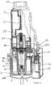
- a rotary pump and its associated motor is shown in Figure 1 and is suitable for use as the pump for a power steering system in a vehicle.
- the rotary pump and integral motor may be mounted either directly on the steering rack or gear box of a vehicle or on the chassis near to the steering rack or on the engine. Indeed, the rotary pump and motor may be mounted anywhere on the vehicle but preferably in the engine bay near to the steering rack. It is preferred that the rotary pump/motor is near to the steering system so as to minimise any delay in response to a demand for power from the steering system and near to the battery to minimise electrical losses.
- the rotary pump is secured by its casing 1 to its mounting point on the vehicle by means of a locating point at its base 1a and two further locating points 2a on a cover member 2. Each of the locating points may include rubber bushings to limit vibration and noise transmission.
- the rotary pump and motor includes a casing 1 within which is located a pump housing 16.
- a cover member 2 and an oil reservoir 3 are secured to the pump housing 16.
- a rotatable shaft 4 is located axially within the casing 1 and the pump housing 16 and has at one end a pump rotor assembly 5 connected to it.
- the elements of the pump may correspond to those of the rotary pump described in US 4659296, the contents of which are incorporated herein by reference although with this embodiment two inlet ports are provided.
- the pump rotor 5 is connected to the shaft 4 by means of spline elements 6 which may be flats, hexagon, key or any other conventional arrangement.
- To one side of the pump rotor 5 a port plate 7 is provided which defines the low and high pressure ports into and out of the pump rotor.
- the high pressure ports 9 are in communication with a discharge conduit 10 which is provided in the cover member 2 and which leads to a discharge port 11.
- the discharge port 11 may be threaded to enable connection to the steering system (not shown).
- a seal 12 is also provided around each of the high pressure ports 9. To ensure accurate positioning of the seals 12, the seals 12 may be formed in a single unit and angularly located to the face of the port plate 7 by means of a pin (not shown).
- an end plate 13 On the opposing side of the pump rotor 5 an end plate 13 is provided which locates in a machine recess in the pump housing 16. Fins 14 define the boundary wall of an oil cavity 15 located about the shaft 4 with the end plate 13 providing inlet ports to the pump rotor from the cavity 15. The fins 14 ensure heat transfer to the oil within the cavity 15 from the pump housing 16 which also functions as a heat sink.
- the end plate 13 therefore defines one end of the oil cavity 15, the other end of the cavity 15, distant from the end plate 13, being closed by an oil seal member 17. Oil is supplied to the cavity 15 by means of an inlet gallery 16a, more clearly seen in Figure 2. Adjacent the oil seal member 17 a bearing 18 is provided which may be conventional in design and which supports the shaft 4 in position with respect to the heat sink 16 and enables relative rotation of the shaft 4.
- the shaft 4 rotates hydrodynamically in the bore of the end plate 13.
- the pump housing 16 encircles the pump rotor 5, end plate 13, and oil cavity 15 and, as mentioned above, functions as a heat sink.
- the heat sink 16 may be made of any suitable thermally massive material, for example aluminium.
- the heat sink 16 is secured to the cover member 2 by means of one or more bolts 19, for example four, or other suitable securing devices.
- the pin (not shown) referred to earlier for locating the oil seals 12 to the port plate 7 may be extended to also angularly locate the cam of the pump and the end plate 13 to one of the fins 14 or to the body of the heat sink 16.
- stator 20 of the electric motor Radially outside of the heat sink 16 is the stator 20 of the electric motor.
- the stator 20 is mounted on an outer wall of a first part of the heat sink 16.
- the windings 21 of the motor which are usually of copper, are wound onto the stator 20.
- the stator 20 forms a tight interference fit to the outer wall of the first part of the heat sink 16.
- the thermal connection between the stator 20 and the heat sink 16 may also be provided by a thermally conductive material between the stator 20 and the heat sink 16.
- the windings 21 are connected to a control circuit device 22 which is mounted on the end of the heat sink 16 distant from the cover member 2.
- the windings 21 are protected from the pump housing or heat sink 16 by means of an electrically insulating ring member 21a.
- the control circuitry 22 is provided on a printed circuit board (pcb) which is secured to the heat sink or pump housing 16 by means of one or more screws 23 or other conventional securing devices.
- One or more FETs 24 form part of the control circuitry 22.
- the FETs 24 are mounted on the lower side of the pcb and are arranged to be in thermal contact with the heat sink 16 by means of a thermal bridge member 22a which may consist of anodised-aluminium so that it also functions as an electrical insulator.
- the FETS may be located in grooves or channels 25 in the heat sink 16.
- Either eight or four FETs 24 are provided with the rotary pump and motor shown in the accompanying figures, although only two are shown.
- the FETs 24 are positioned circumferentially about the heat sink 16.
- control circuitry on the pcb 22 is located in a slot in the wall of the casing 1.
- the FETs 24 in this embodiment are secured to a thermal bridge 22a which is in contact with the pump housing 16.
- the control circuitry including the FETs is positioned radially outside of the motor and so avoids the overall axial length of the integral pump and motor being increased.
- the rotor 26 Radially outside of the stator 20 is provided the rotor 26 thereby forming a brushless motor.
- the rotor 26 has an axially extending wall 26a to which the magnets 27 are secured by any suitable adhesive material such as a cement mixture.
- the arrangement of the magnets 27 is conventional in the form of alternate segments of magnets having different poles. Conventionally 14 segments are employed.
- a radially extending member 26b At one end of the axially extending wall 26a of the rotor 26 there is provided a radially extending member 26b which connects the axially extending wall 26a to the shaft 4.
- an aperture through which the shaft 4 passes is defined by a shaft engaging wall 26c.
- the shaft 4 is held by the shaft engaging wall 26c in a press fit.
- a bearing retainer or collar 40 may also be provided.
- the space axially outside of the rotor 26 but within the casing 1 can be used to hold additional control components for example filter capacitors 42 for use in the suppression of power spikes.
- the power leads 41 are shown extending from the stator 20 around the outside of the rotor 26 to the filter capacitors 42.
- An internal cable shield 44 prevents contact of the leads 41 with the rotor 26.
- the capacitors 42 are connected in parallel between the positive and negative power connections 43 which also provides the control input.
- the cover member 2 and oil reservoir 3 is generally conventional in design.
- the reservoir 3 is arranged to hold 1 ⁇ 2 litre of oil.
- a closable aperture 28 is provided at one end of the reservoir 3 to enable oil to be removed and added.
- a screw threaded lid member 29 is shown in Figure 1.
- the reservoir 3 also includes a vent 29a to accommodate oil volume or fluid level variations.
- An oil return port 30, marked in Figure 1 in dotted lines, provides the inlet port for oil returning from the steering system. The returning oil then passes through a ring filter 31 which is secured at one end to a sprung plate 32 which acts as a pressure limiter.
- the sprung plate 32 which is in the form of fingers to permit oil from the main body of the reservoir 3 to feed to the pump, is arranged to raise the filter 31 from its position against a projecting wall 33 of the cover member 2 in the event the filter 31 becomes blocked. In this way oil entering the return port 30 may pass downstream of the filter 31 in the event, for example, a pressure in excess of 1 ⁇ 2 bar develops upstream of the filter 31.
- the filter 31 may be conventional in design consisting of a paper element secured at each end to steel or rubber end caps 34. Alternatively, the filter 31 may be constructed from nylon mesh.
- the oil reservoir 3 is connected to the cover member 2 through at least one O-ring 35.
- the reservoir 3 is secured to the cover member 2 by means of a snap fit over lugs 2b formed on the periphery of the outer wall of the cover member 2.
- a similar O-ring 36 is located in a groove in the face of the heat sink 16 which abuts against the cover member 2.
- Pressure relief valve means 37 is provided to bring the high pressure discharge conduit 10 in communication with the low pressure inlet gallery 16a, when the pressure of the oil emerging from the high pressure ports 9 exceeds a predetermined value.
- the inlet 38 to the pressure relief valve 37 therefore communicates with the high pressure conduit 10 and the pressure relief outlets 39 communicate with the oil reservoir 3.
- the rotor 26 is positioned and rotates on the outside of the stator 20. Moreover, at least part of the pump housing is located between the shaft and the rotor 26.
- This arrangement provides a number of significant advantages over conventional arrangements of rotary pumps and motors. Firstly, the stator 20 of the motor is in thermal contact with the heat sink 16 which is, in turn, in thermal contact with oil in the cavity 15. Heat generated from the stator 20 is therefore transferred to the oil which is then pumped around the steering system where it is cooled. Similarly the FETs 24 are also in thermal contact with the heat sink so that the heat generated may be transferred to the oil. This significantly reduces the temperature of the casing 1 thereby enabling the rotary pump and motor to be used under the bonnet of a vehicle safely and more significantly maintains the internal components below a temperature which could cause failure.
- the rotor 26 is on the outside of the motor it is larger than conventional rotors and enables the rotor magnets to be made of a ferrite material rather than a rare earth for a given power.
- control circuitry 22 is within the enclosed space of the rotor 26 protects the control circuitry 22 from damage and also provides electrical and magnetic shielding of the control circuitry.
- the casing 1 provides additional shielding. It also allows for a single control/power connection to the outside of the casing 1, as desired.
- control pcb 22 is mounted externally of the rotor 26 but still within the motor casing 1. This too enables the pump and motor to be built and tested as a discrete power unit.
- the arrangement described also enables the rotary pump to be positioned at least partially and ideally wholly within the axial and radial dimensions of the motor. This results in a significantly smaller pump and motor unit in which the pump is integral with the motor by means of the heat sink 16. This also enables the pump and motor to be manufactured as an integral unit requiring one set of tests rather than individually testing the pump and motor separately.
- the pump assembly need not consist of a pumping device in the form of vanes with a rotating carrier and associated cam member.
- the pumping device could consist of two or more gears or a piston with a swash plate or cam mounted on the rotatable shaft.
Abstract
Description
- The present invention relates to a rotary pump and particularly to an electrically driven rotary pump. The present invention is suitable as a pump for vehicle power steering but not exclusively so.
- Pumps used in power assisted steering of vehicles are usually driven mechanically directly from the engine. More recently though electric motor driven pumps have started to be used on vehicles, since they save engine power and fuel and are easier to package in the engine bay. Conventionally these motors are of the brushed d.c. type, and need to be powerful enough to satisfy demands for high power at low vehicle speeds and parking. These high power demands, e.g. up to 1 kilowatt account for only approximately 5% of the operational time of the motor and are short lived, that is the demand is not expected to last more than ten seconds, for example. Significantly lower power, e.g. 30 to 100 watts, is required for approximately 95% of its operational time. Brushless d.c. motors provide better control and can automatically limit in-rush current, unlike conventional motors with brushes. In addition, brushes have poor performance at very high power and will eventually wear out. Therefore, unlike brushed motors, it is possible to over power a brushless motor for brief periods for a given motor size. Conventional brushed and brushless motors consist of a rotating inner wound stator and stationary outer magnets.
- The electrical motors used to drive power assisted steering pumps are commonly mounted adjacent to the pump and require separate assembly and testing. Moreover, difficulties have been experienced as a result of the very high temperatures which are generated by the motor especially when the higher power demands of low speed steering occur. One solution to this has been to completely surround the stator of the motor in oil in order to reduce the temperature of the exterior casing of the motor thereby enabling it to be used safely under the bonnet of the vehicle and preventing failure of its components due to the very high temperatures generated. This has the disadvantage though of significantly reducing the efficiency of the motor.
- It is also the case not only for the above reason but also because of the physical limitation on the size of the motor to enable it to be mounted under the vehicle bonnet, that the rotor magnet conventionally consists of a rare earth to meet the power demands of the system which significantly increases the cost of the component.
- The present invention seeks to overcome at least partly the difficulties identified above with respect to conventional motors for power steering pumps. In this respect the present invention seeks to provide an integral pump and motor which is compact and yet capable of meeting the power demands of a vehicle steering system and which reduces the problems associated with the high temperatures involved in a simple yet cost effective manner.
- The present invention provides in a first aspect a rotary pump assembly having at least one inlet port, at least one outlet port, a housing and a pumping device in fluid communication with the inlet and outlet ports, the pumping device including a pump driver member mounted on a rotatable shaft which is connected to the rotor of an electric motor, a portion of the housing being located radially between the shaft and the rotor of the motor and having the stator of the motor mounted thereon.
- The fluid pump includes a cavity in communication with the inlet port which may be located about the rotatable shaft.
- With the "inside-out" construction described above, that is a stationary inner wound stator and rotating magnets, more power can be gained for a given physical size of motor. For reasons of cost and size it is preferred that a lower rated motor is employed which is capable of accommodating the brief demands for high power. With the present invention which utilises the "inside-out" construction of a brushless d.c. motor as described, it is possible to employ a lower rated motor than has formerly been the case. Ideally means of conducting away from sensitive components the heat which is generated by such a motor at high power levels is also provided.
- In a preferred embodiment the housing is a heat sink and is in thermal contact with the copper wound stator of the electric motor. Also the housing in the form of the heat sink may define at least partially the boundary of the cavity connecting a fluid reservoir to the at least one pump inlet.
- In an additional preferred embodiment the circuitry for controlling the electric motor may be mounted on the pump housing radially between the shaft and the rotor. Ideally the housing is a heat sink and at least some of the circuitry may be in thermal contact with the heat sink.
- Preferably the rotary pump is integral with the electric motor.
- The present invention will now be described by way of example only with reference to the accompanying drawings, in which:
- Figure 1 is a first axial sectional view through an integral rotary pump and motor in accordance with a first embodiment of the present invention;
- Figure 2 is a second axial section view through the integral rotary pump and motor of Figure 1;
- Figure 3 is a radial sectional view along the line A-A in Figure 1;
- Figure 4 is a plan view from above cut-away along the line B- in Figure 2;
- Figure 5 is a first axial sectional view through an integral rotary pump and motor in accordance with a second embodiment of the present invention; and
- Figure 6 is an axial sectional view through an integral rotary pump and motor in accordance with a third embodiment of the present invention.
-
- A rotary pump and its associated motor is shown in Figure 1 and is suitable for use as the pump for a power steering system in a vehicle. The rotary pump and integral motor may be mounted either directly on the steering rack or gear box of a vehicle or on the chassis near to the steering rack or on the engine. Indeed, the rotary pump and motor may be mounted anywhere on the vehicle but preferably in the engine bay near to the steering rack. It is preferred that the rotary pump/motor is near to the steering system so as to minimise any delay in response to a demand for power from the steering system and near to the battery to minimise electrical losses. The rotary pump is secured by its
casing 1 to its mounting point on the vehicle by means of a locating point at its base 1a and two further locatingpoints 2a on acover member 2. Each of the locating points may include rubber bushings to limit vibration and noise transmission. - The rotary pump and motor includes a
casing 1 within which is located apump housing 16. Acover member 2 and anoil reservoir 3 are secured to thepump housing 16. Arotatable shaft 4 is located axially within thecasing 1 and thepump housing 16 and has at one end apump rotor assembly 5 connected to it. The elements of the pump may correspond to those of the rotary pump described in US 4659296, the contents of which are incorporated herein by reference although with this embodiment two inlet ports are provided. Thepump rotor 5 is connected to theshaft 4 by means ofspline elements 6 which may be flats, hexagon, key or any other conventional arrangement. To one side of the pump rotor 5 aport plate 7 is provided which defines the low and high pressure ports into and out of the pump rotor. There are twolow pressure ports 8 and twohigh pressure ports 9 which are shown more clearly in Figure 3. Thehigh pressure ports 9 are in communication with adischarge conduit 10 which is provided in thecover member 2 and which leads to adischarge port 11. Thedischarge port 11 may be threaded to enable connection to the steering system (not shown). Aseal 12 is also provided around each of thehigh pressure ports 9. To ensure accurate positioning of theseals 12, theseals 12 may be formed in a single unit and angularly located to the face of theport plate 7 by means of a pin (not shown). - On the opposing side of the
pump rotor 5 anend plate 13 is provided which locates in a machine recess in thepump housing 16. Fins 14 define the boundary wall of anoil cavity 15 located about theshaft 4 with theend plate 13 providing inlet ports to the pump rotor from thecavity 15. Thefins 14 ensure heat transfer to the oil within thecavity 15 from thepump housing 16 which also functions as a heat sink. Theend plate 13 therefore defines one end of theoil cavity 15, the other end of thecavity 15, distant from theend plate 13, being closed by anoil seal member 17. Oil is supplied to thecavity 15 by means of aninlet gallery 16a, more clearly seen in Figure 2. Adjacent the oil seal member 17 abearing 18 is provided which may be conventional in design and which supports theshaft 4 in position with respect to theheat sink 16 and enables relative rotation of theshaft 4. Theshaft 4 rotates hydrodynamically in the bore of theend plate 13. - The pump housing 16 encircles the
pump rotor 5,end plate 13, andoil cavity 15 and, as mentioned above, functions as a heat sink. Theheat sink 16 may be made of any suitable thermally massive material, for example aluminium. Theheat sink 16 is secured to thecover member 2 by means of one ormore bolts 19, for example four, or other suitable securing devices. The pin (not shown) referred to earlier for locating the oil seals 12 to theport plate 7 may be extended to also angularly locate the cam of the pump and theend plate 13 to one of thefins 14 or to the body of theheat sink 16. - Radially outside of the
heat sink 16 is thestator 20 of the electric motor. Thestator 20 is mounted on an outer wall of a first part of theheat sink 16. Thewindings 21 of the motor, which are usually of copper, are wound onto thestator 20. Thestator 20 forms a tight interference fit to the outer wall of the first part of theheat sink 16. Thus, good thermal contact is established between the copper wound stator and theheat sink 16. The thermal connection between thestator 20 and theheat sink 16 may also be provided by a thermally conductive material between thestator 20 and theheat sink 16. Thewindings 21 are connected to acontrol circuit device 22 which is mounted on the end of theheat sink 16 distant from thecover member 2. Thewindings 21 are protected from the pump housing orheat sink 16 by means of an electrically insulatingring member 21a. - The
control circuitry 22 is provided on a printed circuit board (pcb) which is secured to the heat sink or pumphousing 16 by means of one ormore screws 23 or other conventional securing devices. One ormore FETs 24 form part of thecontrol circuitry 22. In Figure 1 theFETs 24 are mounted on the lower side of the pcb and are arranged to be in thermal contact with theheat sink 16 by means of athermal bridge member 22a which may consist of anodised-aluminium so that it also functions as an electrical insulator. Alternatively, as shown in Figure 5, the FETS may be located in grooves orchannels 25 in theheat sink 16. Either eight or fourFETs 24 are provided with the rotary pump and motor shown in the accompanying figures, although only two are shown. TheFETs 24 are positioned circumferentially about theheat sink 16. - In the case of Figure 6 the control circuitry on the
pcb 22 is located in a slot in the wall of thecasing 1. TheFETs 24 in this embodiment are secured to athermal bridge 22a which is in contact with thepump housing 16. Thus, as may be seen in Figure 6, the control circuitry including the FETs is positioned radially outside of the motor and so avoids the overall axial length of the integral pump and motor being increased. - Radially outside of the
stator 20 is provided therotor 26 thereby forming a brushless motor. Therotor 26 has anaxially extending wall 26a to which themagnets 27 are secured by any suitable adhesive material such as a cement mixture. The arrangement of themagnets 27 is conventional in the form of alternate segments of magnets having different poles. Conventionally 14 segments are employed. At one end of theaxially extending wall 26a of therotor 26 there is provided a radially extending member 26b which connects theaxially extending wall 26a to theshaft 4. At the end of the radially extending member 26b adjacent theshaft 4 an aperture through which theshaft 4 passes is defined by ashaft engaging wall 26c. Theshaft 4 is held by theshaft engaging wall 26c in a press fit. A bearing retainer orcollar 40 may also be provided. - As shown in Figures 1 and 2, the space axially outside of the
rotor 26 but within thecasing 1 can be used to hold additional control components forexample filter capacitors 42 for use in the suppression of power spikes. The power leads 41 are shown extending from thestator 20 around the outside of therotor 26 to thefilter capacitors 42. Aninternal cable shield 44 prevents contact of theleads 41 with therotor 26. Thecapacitors 42 are connected in parallel between the positive andnegative power connections 43 which also provides the control input. - In Figure 6, it will be seen that the
filter capacitors 42 and additional control components are positioned with thepcb 22 radially outside of the motor. Theelectrical connections 43 are similarly provided on the casing distant from therotor 26. - With reference to the upper portion of Figures 1, 2, 5 and 6, the
cover member 2 andoil reservoir 3 is generally conventional in design. Thereservoir 3 is arranged to hold ½ litre of oil. Aclosable aperture 28 is provided at one end of thereservoir 3 to enable oil to be removed and added. A screw threadedlid member 29 is shown in Figure 1. Thereservoir 3 also includes avent 29a to accommodate oil volume or fluid level variations. Anoil return port 30, marked in Figure 1 in dotted lines, provides the inlet port for oil returning from the steering system. The returning oil then passes through aring filter 31 which is secured at one end to a sprungplate 32 which acts as a pressure limiter. The sprungplate 32, which is in the form of fingers to permit oil from the main body of thereservoir 3 to feed to the pump, is arranged to raise thefilter 31 from its position against a projectingwall 33 of thecover member 2 in the event thefilter 31 becomes blocked. In this way oil entering thereturn port 30 may pass downstream of thefilter 31 in the event, for example, a pressure in excess of ½ bar develops upstream of thefilter 31. Thefilter 31 may be conventional in design consisting of a paper element secured at each end to steel or rubber end caps 34. Alternatively, thefilter 31 may be constructed from nylon mesh. - The
oil reservoir 3 is connected to thecover member 2 through at least one O-ring 35. Thereservoir 3 is secured to thecover member 2 by means of a snap fit over lugs 2b formed on the periphery of the outer wall of thecover member 2. A similar O-ring 36 is located in a groove in the face of theheat sink 16 which abuts against thecover member 2. - Pressure relief valve means 37 is provided to bring the high
pressure discharge conduit 10 in communication with the lowpressure inlet gallery 16a, when the pressure of the oil emerging from thehigh pressure ports 9 exceeds a predetermined value. Theinlet 38 to thepressure relief valve 37 therefore communicates with thehigh pressure conduit 10 and thepressure relief outlets 39 communicate with theoil reservoir 3. - In Figure 1 the
high pressure ports 9 and the highpressure discharge outlet 11 is shown. In Figure 2, on the other hand, the communication of theoil cavity 15 with thelow pressure ports 8 is shown. Thelow pressure galleries 16a are shown and, as may be clearly seen, thegalleries 16a are defined by the wall of the heat sink or pumphousing 16 and the rotary pump assembly. Theinlet galleries 16a provide the fluid connection between thereservoir 3 and thecavity 15. - It will be appreciated that unlike conventional motors used with rotary pumps, the
rotor 26 is positioned and rotates on the outside of thestator 20. Moreover, at least part of the pump housing is located between the shaft and therotor 26. This arrangement provides a number of significant advantages over conventional arrangements of rotary pumps and motors. Firstly, thestator 20 of the motor is in thermal contact with theheat sink 16 which is, in turn, in thermal contact with oil in thecavity 15. Heat generated from thestator 20 is therefore transferred to the oil which is then pumped around the steering system where it is cooled. Similarly theFETs 24 are also in thermal contact with the heat sink so that the heat generated may be transferred to the oil. This significantly reduces the temperature of thecasing 1 thereby enabling the rotary pump and motor to be used under the bonnet of a vehicle safely and more significantly maintains the internal components below a temperature which could cause failure. - Also, because the
rotor 26 is on the outside of the motor it is larger than conventional rotors and enables the rotor magnets to be made of a ferrite material rather than a rare earth for a given power. - In the case of Figures 1 to 5, the fact that the
control circuitry 22 is within the enclosed space of therotor 26 protects thecontrol circuitry 22 from damage and also provides electrical and magnetic shielding of the control circuitry. Thecasing 1 provides additional shielding. It also allows for a single control/power connection to the outside of thecasing 1, as desired. In the embodiment of Figure 6, thecontrol pcb 22 is mounted externally of therotor 26 but still within themotor casing 1. This too enables the pump and motor to be built and tested as a discrete power unit. - As may be seen clearly in the Figures, the arrangement described also enables the rotary pump to be positioned at least partially and ideally wholly within the axial and radial dimensions of the motor. This results in a significantly smaller pump and motor unit in which the pump is integral with the motor by means of the
heat sink 16. This also enables the pump and motor to be manufactured as an integral unit requiring one set of tests rather than individually testing the pump and motor separately. - It will be appreciated that the pump assembly need not consist of a pumping device in the form of vanes with a rotating carrier and associated cam member. Alternatively, the pumping device could consist of two or more gears or a piston with a swash plate or cam mounted on the rotatable shaft.
- Alternative arrangements and functionally equivalent components are envisaged whilst remaining within the spirit and scope of the present invention claimed in the accompanying claims.
Claims (17)
- A rotary pump assembly having at least one inlet port, at least one outlet port, a housing and a pumping device in fluid communication with the inlet and outlet ports, the pumping device including a pump driver member mounted on a rotatable shaft which is connected to the rotor of an electric motor, a portion of the housing being located radially between the shaft and the rotor of the motor and having the stator of the motor mounted thereon.
- A rotary pump assembly as claimed in claim 1, wherein the stator is mounted on an outer surface of the housing.
- A rotary pump assembly as claimed in either of claims 1 or 2, wherein the housing is a heat sink.
- A rotary pump assembly as claimed in claim 3, wherein a thermally conductive material is provided between the stator and the outer surface of the housing.
- A rotary pump assembly as claimed in any one of claims 1 to 4, wherein a fluid cavity connecting a fluid supply to at least one inlet port is provided within the housing.
- A rotary pump assembly as claimed in claim 5, wherein the fluid cavity is defined by a portion of the outer surface of the shaft and an inner wall of the housing.
- A rotary pump assembly as claimed in claim 6, wherein the inner wall of the housing includes thermally conductive fins.
- A rotary pump assembly as claimed in any one of claims 5 to 7, wherein the fluid cavity is wholly located radially between the shaft and the rotor of the electric motor.
- A rotary pump assembly as claimed in any one of the preceding claims, wherein circuitry for controlling operation of the electric motor is mounted on the housing radially between the shaft and the rotor of the electric motor.
- A rotary pump assembly as claimed in claim 9 and claim 3, wherein at least one of the components of the circuitry is in thermal contact with the housing.
- A rotary pump assembly as claimed in either of claims 9 or 10, wherein the rotor of the electric motor includes an axially extending magnetic part and a radially extending part which connects the axially extending magnetic part to the shaft and the circuitry is located with the space defined by the shaft, the radially extending part and the axially extending part of the rotor.
- A rotary pump assembly as claimed in any one of the preceding claims, wherein the pumping device has a plurality of roller vanes located in a rotating carrier and an associated cam member.
- A rotary pump assembly as claimed in any one of claims 1 to 11, wherein the pumping device has a plurality of flat vanes located in a rotating carrier and an associated cam member.
- A rotary pump assembly as claimed in any one of claims 1 to 11, wherein the pumping device includes a plurality of gear members.
- A rotary pump assembly as claimed in any one of claims 1 to 11, wherein the pumping device includes at least one piston and the pump driver member is a swash plate or cam mounted on the rotatable shaft.
- A rotary pump assembly as claimed in any one of the preceding claims being integral with the electric motor.
- A rotary pump assembly as claimed in any one of the preceding claims arranged for use in a vehicle power steering system.
Applications Claiming Priority (5)
| Application Number | Priority Date | Filing Date | Title |
|---|---|---|---|
| GB9422448A GB9422448D0 (en) | 1994-11-07 | 1994-11-07 | Rotary pump |
| GB9422448 | 1994-11-07 | ||
| GB9424053 | 1994-11-29 | ||
| GB9424053A GB9424053D0 (en) | 1994-11-29 | 1994-11-29 | Rotary pump |
| EP95936639A EP0742872B1 (en) | 1994-11-07 | 1995-11-06 | Rotary pump and motor assembly |
Related Parent Applications (1)
| Application Number | Title | Priority Date | Filing Date |
|---|---|---|---|
| EP95936639A Division EP0742872B1 (en) | 1994-11-07 | 1995-11-06 | Rotary pump and motor assembly |
Publications (2)
| Publication Number | Publication Date |
|---|---|
| EP0953770A1 true EP0953770A1 (en) | 1999-11-03 |
| EP0953770B1 EP0953770B1 (en) | 2004-07-21 |
Family
ID=26305944
Family Applications (2)
| Application Number | Title | Priority Date | Filing Date |
|---|---|---|---|
| EP99112841A Expired - Lifetime EP0953770B1 (en) | 1994-11-07 | 1995-11-06 | Rotary pump and motor assembly |
| EP95936639A Expired - Lifetime EP0742872B1 (en) | 1994-11-07 | 1995-11-06 | Rotary pump and motor assembly |
Family Applications After (1)
| Application Number | Title | Priority Date | Filing Date |
|---|---|---|---|
| EP95936639A Expired - Lifetime EP0742872B1 (en) | 1994-11-07 | 1995-11-06 | Rotary pump and motor assembly |
Country Status (9)
| Country | Link |
|---|---|
| US (2) | US5810568A (en) |
| EP (2) | EP0953770B1 (en) |
| JP (1) | JP3872104B2 (en) |
| AT (2) | ATE185403T1 (en) |
| DE (2) | DE69512637T2 (en) |
| DK (1) | DK0742872T3 (en) |
| ES (2) | ES2226242T3 (en) |
| GR (1) | GR3032324T3 (en) |
| WO (1) | WO1996014511A1 (en) |
Cited By (1)
| Publication number | Priority date | Publication date | Assignee | Title |
|---|---|---|---|---|
| EP0999115A4 (en) * | 1998-05-21 | 2005-04-06 | Koyo Seiko Co | Power steering device |
Families Citing this family (51)
| Publication number | Priority date | Publication date | Assignee | Title |
|---|---|---|---|---|
| WO1996014511A1 (en) * | 1994-11-07 | 1996-05-17 | Hobourn Automotive Limited | Rotary pump and motor assembly |
| US6158983A (en) * | 1997-04-24 | 2000-12-12 | Trw Inc. | Pump having muffler for attenuating noise |
| DE19833372A1 (en) * | 1998-07-24 | 2000-01-27 | Zahnradfabrik Friedrichshafen | Gear pump for vehicle power steering, integrated in casing and surrounded by absorber cavity and induction cavity |
| US6499966B1 (en) | 1998-08-06 | 2002-12-31 | Automative Motion Technology, Ltd. | Motor driven pump |
| GB9817155D0 (en) * | 1998-08-06 | 1998-10-07 | Automotive Motion Tech Ltd | Screw pump |
| DE19903817A1 (en) * | 1999-02-02 | 2000-08-10 | Bosch Gmbh Robert | Cooling water pump |
| FR2789446B1 (en) † | 1999-02-04 | 2002-03-08 | Hydroperfect Internat Hpi | HYDRAULIC PUMP OF THE GEAR TYPE AND ELECTRIC PUMP GROUP EQUIPPED WITH SUCH A PUMP |
| US6203779B1 (en) * | 1999-03-19 | 2001-03-20 | Charlie Ricci | Methods for treating endoleaks during endovascular repair of abdominal aortic aneurysms |
| US6231318B1 (en) | 1999-03-29 | 2001-05-15 | Walbro Corporation | In-take fuel pump reservoir |
| US6227819B1 (en) | 1999-03-29 | 2001-05-08 | Walbro Corporation | Fuel pumping assembly |
| US6281607B1 (en) * | 1999-04-06 | 2001-08-28 | Trw Inc. | Electric motor with vibration attenuation |
| GB9913969D0 (en) | 1999-06-16 | 1999-08-18 | Boc Group Plc | Improvements in screw pumps |
| US6135726A (en) * | 1999-09-23 | 2000-10-24 | Ford Motor Company | Power steering power pack motor/pump mounting bracket |
| DE19958927C1 (en) * | 1999-12-07 | 2001-06-13 | Lucas Varity Gmbh | Vehicle brake system with a motor / pump unit and a unit |
| KR100328998B1 (en) | 1999-12-13 | 2002-03-20 | 류정열 | Structure for assembling pressure pipe to oil pump in a power steering system for a motor vehicle |
| US6652249B2 (en) | 1999-12-13 | 2003-11-25 | Parker-Hannifin Corporation | Brushless DC wet motor fuel pump with integral controller |
| US6257364B1 (en) * | 2000-01-20 | 2001-07-10 | Ford Global Technologies, Inc. | Submersible electro-hydraulic powerpack for underhood automotive steering applications |
| US6227452B1 (en) | 2000-01-29 | 2001-05-08 | Daimlerchrysler Corporation | Combined assembly for a power steering pump and a viscous heater |
| AU2001236883A1 (en) * | 2000-02-09 | 2001-08-20 | Parker-Hannifin Corporation | Brushless dc wet motor fuel pump with integral controller |
| US6419042B1 (en) | 2000-10-03 | 2002-07-16 | Trw Inc. | Integrated electric power hydraulic steering system |
| US6659737B2 (en) | 2001-02-05 | 2003-12-09 | Engineered Machined Products, Inc. | Electronic fluid pump with an encapsulated stator assembly |
| DE20117795U1 (en) * | 2001-10-31 | 2002-03-07 | Trw Automotive Electron & Comp | Drive unit for actuating a parking brake in a vehicle |
| US6685447B2 (en) * | 2002-01-25 | 2004-02-03 | Hamilton Sundstrand | Liquid cooled integrated rotordynamic motor/generator station with sealed power electronic controls |
| US6702555B2 (en) | 2002-07-17 | 2004-03-09 | Engineered Machined Products, Inc. | Fluid pump having an isolated stator assembly |
| DE20302534U1 (en) * | 2003-02-17 | 2003-06-18 | Trw Fahrwerksyst Gmbh & Co | Motor-pump assembly |
| EP1482175B1 (en) * | 2003-05-28 | 2009-10-14 | Aisin Seiki Kabushiki Kaisha | Electric powered pump |
| US6960851B2 (en) * | 2003-12-02 | 2005-11-01 | Tm4 Inc. | Cooling device including a biasing element |
| JP4272112B2 (en) * | 2004-05-26 | 2009-06-03 | 株式会社日立製作所 | Motor-integrated internal gear pump and electronic equipment |
| US7162887B2 (en) * | 2004-07-09 | 2007-01-16 | Symons Robert S | Integrated liquid cooling device for electronic components |
| US7165413B2 (en) * | 2004-07-09 | 2007-01-23 | Symons Robert S | Integrated liquid cooling device with immersed electronic components |
| KR20080016863A (en) * | 2005-05-17 | 2008-02-22 | 페더럴-모걸 코오포레이숀 | Bldc motor and pump assembly with encapsulated circuit board |
| US7282875B2 (en) * | 2005-08-31 | 2007-10-16 | Caterpillar Inc. | System and method for electric motor control |
| US7931448B2 (en) * | 2006-08-01 | 2011-04-26 | Federal Mogul World Wide, Inc. | System and method for manufacturing a brushless DC motor fluid pump |
| US7847457B2 (en) | 2007-05-09 | 2010-12-07 | Federal-Mogul World Wide, Inc | BLDC motor assembly |
| US20110052428A1 (en) * | 2008-01-16 | 2011-03-03 | Superpar Otomotiv Sanayi Ve Ticaret Anonim Sirketi | Electric fuel pump for heavy duty engine platforms |
| CN102177343B (en) * | 2008-10-14 | 2014-04-02 | 株式会社捷太格特 | Electric pump unit |
| US9744300B2 (en) | 2011-12-21 | 2017-08-29 | Deka Products Limited Partnership | Syringe pump and related method |
| US9789247B2 (en) | 2011-12-21 | 2017-10-17 | Deka Products Limited Partnership | Syringe pump, and related method and system |
| US9295778B2 (en) | 2011-12-21 | 2016-03-29 | Deka Products Limited Partnership | Syringe pump |
| US9091377B2 (en) * | 2010-02-19 | 2015-07-28 | Gabriel V. Lechuga | Insulated pipe and duct mounting arrangement |
| JP5927766B2 (en) * | 2011-03-11 | 2016-06-01 | 株式会社ジェイテクト | Electric pump unit |
| US11217340B2 (en) | 2011-12-21 | 2022-01-04 | Deka Products Limited Partnership | Syringe pump having a pressure sensor assembly |
| US10722645B2 (en) | 2011-12-21 | 2020-07-28 | Deka Products Limited Partnership | Syringe pump, and related method and system |
| US9543811B2 (en) * | 2012-09-14 | 2017-01-10 | Rockwell Automation Technologies, Inc. | Heatsink design with thermal insulator to reduce encoder temperature |
| US10135321B2 (en) | 2012-09-14 | 2018-11-20 | Rockwell Automation Technologies, Inc. | Heatsink design with thermal insulator to reduce encoder temperature |
| JP6042746B2 (en) * | 2013-02-25 | 2016-12-14 | 愛三工業株式会社 | Electric pump |
| WO2015127189A1 (en) | 2014-02-21 | 2015-08-27 | Deka Products Limited Partnership | Syringe pump having a pressure sensor assembly |
| JP7135388B2 (en) * | 2018-03-30 | 2022-09-13 | 日本電産トーソク株式会社 | electric oil pump |
| US10590939B2 (en) * | 2018-04-20 | 2020-03-17 | Tuthill Corporation | Fluid pump assembly |
| EP3947969A1 (en) * | 2019-04-03 | 2022-02-09 | Maersk Container Industry A/S | Compressor or pump housing assembly and method of assembly of a compressor or pump housing |
| US11852152B2 (en) | 2019-10-07 | 2023-12-26 | The Gorman-Rupp Company | Pin vent assembly |
Citations (6)
| Publication number | Priority date | Publication date | Assignee | Title |
|---|---|---|---|---|
| GB699436A (en) * | 1952-03-13 | 1953-11-04 | Mono Pumps Ltd | Improvements in or relating to electrically driven pump units |
| GB743739A (en) * | 1952-07-11 | 1956-01-25 | Albert Richard | Improvements in circulating pump devices |
| US2938468A (en) * | 1957-09-13 | 1960-05-31 | Allis Chalmers Mfg Co | Fluid pump |
| US5098256A (en) * | 1989-11-21 | 1992-03-24 | The Cleveland Clinic Foundation | Viscous seal blood pump |
| EP0481423A1 (en) * | 1990-10-16 | 1992-04-22 | Micropump Corporation | Electric pump assembly |
| WO1992018774A1 (en) * | 1991-04-10 | 1992-10-29 | Magnet-Motor Gesellschaft Für Magnetmotorische Technik Mbh | Pump for fluids |
Family Cites Families (12)
| Publication number | Priority date | Publication date | Assignee | Title |
|---|---|---|---|---|
| US765078A (en) * | 1902-12-01 | 1904-07-12 | Paul Jigouzo | Asynchronous motor. |
| US2548799A (en) * | 1948-01-07 | 1951-04-10 | A P Controls Corp | Pump |
| US2768583A (en) * | 1952-07-11 | 1956-10-30 | Emerjy Soc | Circulating pump devices |
| DE1553116B2 (en) * | 1966-10-25 | 1971-07-15 | Licentia Patent Verwaltungs GmbH, 6000 Frankfurt | Electric motor-operated gear oil pump |
| JPS56159598A (en) * | 1980-05-14 | 1981-12-08 | Hitachi Ltd | Brushless motor fan |
| GB2227793B (en) * | 1985-11-08 | 1990-10-31 | Papst Motoren Gmbh & Co Kg | Miniature axial fan |
| US4739204A (en) * | 1986-01-30 | 1988-04-19 | Mitsubishi Denki Kabushiki Kaisha | Liquid cooled a.c. vehicle generator |
| DE3705909A1 (en) * | 1987-02-24 | 1988-09-01 | Heilmeier & Weinlein | HYDRAULIC PUMP UNIT |
| US4836147A (en) * | 1987-12-14 | 1989-06-06 | Ford Motor Company | Cooling system for an internal combustion engine |
| DE4137103C2 (en) * | 1991-11-12 | 1994-02-17 | Elmeg | Electro-hydraulic device |
| IT1273198B (en) * | 1994-05-12 | 1997-07-07 | Bitron A Spa | IMPROVEMENTS TO AN ELECTRONICALLY COMMUTED FAN FOR THE CABIN OF A VEHICLE |
| WO1996014511A1 (en) | 1994-11-07 | 1996-05-17 | Hobourn Automotive Limited | Rotary pump and motor assembly |
-
1995
- 1995-11-06 WO PCT/GB1995/002621 patent/WO1996014511A1/en active IP Right Grant
- 1995-11-06 ES ES99112841T patent/ES2226242T3/en not_active Expired - Lifetime
- 1995-11-06 ES ES95936639T patent/ES2140715T3/en not_active Expired - Lifetime
- 1995-11-06 AT AT95936639T patent/ATE185403T1/en not_active IP Right Cessation
- 1995-11-06 DE DE69512637T patent/DE69512637T2/en not_active Expired - Lifetime
- 1995-11-06 DE DE69533291T patent/DE69533291T2/en not_active Expired - Lifetime
- 1995-11-06 US US08/669,366 patent/US5810568A/en not_active Expired - Fee Related
- 1995-11-06 EP EP99112841A patent/EP0953770B1/en not_active Expired - Lifetime
- 1995-11-06 AT AT99112841T patent/ATE271657T1/en not_active IP Right Cessation
- 1995-11-06 EP EP95936639A patent/EP0742872B1/en not_active Expired - Lifetime
- 1995-11-06 DK DK95936639T patent/DK0742872T3/en active
- 1995-11-06 JP JP51515396A patent/JP3872104B2/en not_active Expired - Fee Related
-
1997
- 1997-12-19 US US08/994,643 patent/US6030187A/en not_active Expired - Fee Related
-
2000
- 2000-01-07 GR GR20000400022T patent/GR3032324T3/en not_active IP Right Cessation
Patent Citations (6)
| Publication number | Priority date | Publication date | Assignee | Title |
|---|---|---|---|---|
| GB699436A (en) * | 1952-03-13 | 1953-11-04 | Mono Pumps Ltd | Improvements in or relating to electrically driven pump units |
| GB743739A (en) * | 1952-07-11 | 1956-01-25 | Albert Richard | Improvements in circulating pump devices |
| US2938468A (en) * | 1957-09-13 | 1960-05-31 | Allis Chalmers Mfg Co | Fluid pump |
| US5098256A (en) * | 1989-11-21 | 1992-03-24 | The Cleveland Clinic Foundation | Viscous seal blood pump |
| EP0481423A1 (en) * | 1990-10-16 | 1992-04-22 | Micropump Corporation | Electric pump assembly |
| WO1992018774A1 (en) * | 1991-04-10 | 1992-10-29 | Magnet-Motor Gesellschaft Für Magnetmotorische Technik Mbh | Pump for fluids |
Cited By (1)
| Publication number | Priority date | Publication date | Assignee | Title |
|---|---|---|---|---|
| EP0999115A4 (en) * | 1998-05-21 | 2005-04-06 | Koyo Seiko Co | Power steering device |
Also Published As
| Publication number | Publication date |
|---|---|
| DE69512637T2 (en) | 2000-05-18 |
| ATE185403T1 (en) | 1999-10-15 |
| EP0742872B1 (en) | 1999-10-06 |
| DE69533291T2 (en) | 2005-08-25 |
| ES2140715T3 (en) | 2000-03-01 |
| EP0953770B1 (en) | 2004-07-21 |
| DK0742872T3 (en) | 2000-04-17 |
| WO1996014511A1 (en) | 1996-05-17 |
| DE69533291D1 (en) | 2004-08-26 |
| US5810568A (en) | 1998-09-22 |
| ES2226242T3 (en) | 2005-03-16 |
| ATE271657T1 (en) | 2004-08-15 |
| EP0742872A1 (en) | 1996-11-20 |
| JP3872104B2 (en) | 2007-01-24 |
| DE69512637D1 (en) | 1999-11-11 |
| US6030187A (en) | 2000-02-29 |
| GR3032324T3 (en) | 2000-04-27 |
| JPH09507892A (en) | 1997-08-12 |
Similar Documents
| Publication | Publication Date | Title |
|---|---|---|
| US5810568A (en) | Rotary pump with a thermally conductive housing | |
| US9169833B2 (en) | Device for fastening and electrically connecting a circuit board to a motor | |
| EP2326827B1 (en) | Electrical machine | |
| US6986648B2 (en) | Electric pump | |
| EP1302704B1 (en) | Submerged electric fluid pump | |
| JP7090170B2 (en) | Electric vehicle auxiliary unit | |
| US6571895B2 (en) | Electrical machine, and a drive arrangement for a vehicle | |
| CN110836179A (en) | Mounting structure of electric pump | |
| EP3488672B1 (en) | Pump assembly having integrated controller and motor with internal active cooling | |
| JP5915082B2 (en) | Electric oil pump device | |
| US20220128057A1 (en) | Electric coolant pump | |
| EP4230869A1 (en) | Electric oil pump | |
| US20210285443A1 (en) | Pump Insert And Pump Array Comprising Such a Pump Insert | |
| KR20140145491A (en) | Electric Pump | |
| SU1554076A1 (en) | Submersible oil-filled electric motor |
Legal Events
| Date | Code | Title | Description |
|---|---|---|---|
| PUAI | Public reference made under article 153(3) epc to a published international application that has entered the european phase |
Free format text: ORIGINAL CODE: 0009012 |
|
| 17P | Request for examination filed |
Effective date: 19990702 |
|
| AC | Divisional application: reference to earlier application |
Ref document number: 742872 Country of ref document: EP |
|
| AK | Designated contracting states |
Kind code of ref document: A1 Designated state(s): AT BE CH DE DK ES FR GB GR IE IT LI LU MC NL PT SE |
|
| RIN1 | Information on inventor provided before grant (corrected) |
Inventor name: BASELEY, SIMON JOHN Inventor name: WHITEFIELD, KEVIN |
|
| AKX | Designation fees paid |
Free format text: AT BE CH DE DK ES FR GB GR IE IT LI LU MC NL PT SE |
|
| RAP1 | Party data changed (applicant data changed or rights of an application transferred) |
Owner name: DANA AUTOMOTIVE LIMITED |
|
| 17Q | First examination report despatched |
Effective date: 20021015 |
|
| GRAP | Despatch of communication of intention to grant a patent |
Free format text: ORIGINAL CODE: EPIDOSNIGR1 |
|
| GRAS | Grant fee paid |
Free format text: ORIGINAL CODE: EPIDOSNIGR3 |
|
| GRAA | (expected) grant |
Free format text: ORIGINAL CODE: 0009210 |
|
| AC | Divisional application: reference to earlier application |
Ref document number: 0742872 Country of ref document: EP Kind code of ref document: P |
|
| AK | Designated contracting states |
Kind code of ref document: B1 Designated state(s): AT BE CH DE DK ES FR GB GR IE IT LI LU MC NL PT SE |
|
| PG25 | Lapsed in a contracting state [announced via postgrant information from national office to epo] |
Ref country code: LI Free format text: LAPSE BECAUSE OF FAILURE TO SUBMIT A TRANSLATION OF THE DESCRIPTION OR TO PAY THE FEE WITHIN THE PRESCRIBED TIME-LIMIT Effective date: 20040721 Ref country code: CH Free format text: LAPSE BECAUSE OF FAILURE TO SUBMIT A TRANSLATION OF THE DESCRIPTION OR TO PAY THE FEE WITHIN THE PRESCRIBED TIME-LIMIT Effective date: 20040721 Ref country code: BE Free format text: LAPSE BECAUSE OF FAILURE TO SUBMIT A TRANSLATION OF THE DESCRIPTION OR TO PAY THE FEE WITHIN THE PRESCRIBED TIME-LIMIT Effective date: 20040721 |
|
| REG | Reference to a national code |
Ref country code: GB Ref legal event code: FG4D |
|
| REG | Reference to a national code |
Ref country code: CH Ref legal event code: EP |
|
| REG | Reference to a national code |
Ref country code: IE Ref legal event code: FG4D |
|
| REF | Corresponds to: |
Ref document number: 69533291 Country of ref document: DE Date of ref document: 20040826 Kind code of ref document: P |
|
| PG25 | Lapsed in a contracting state [announced via postgrant information from national office to epo] |
Ref country code: GR Free format text: LAPSE BECAUSE OF FAILURE TO SUBMIT A TRANSLATION OF THE DESCRIPTION OR TO PAY THE FEE WITHIN THE PRESCRIBED TIME-LIMIT Effective date: 20041021 Ref country code: DK Free format text: LAPSE BECAUSE OF FAILURE TO SUBMIT A TRANSLATION OF THE DESCRIPTION OR TO PAY THE FEE WITHIN THE PRESCRIBED TIME-LIMIT Effective date: 20041021 |
|
| PG25 | Lapsed in a contracting state [announced via postgrant information from national office to epo] |
Ref country code: LU Free format text: LAPSE BECAUSE OF NON-PAYMENT OF DUE FEES Effective date: 20041106 |
|
| PG25 | Lapsed in a contracting state [announced via postgrant information from national office to epo] |
Ref country code: IE Free format text: LAPSE BECAUSE OF NON-PAYMENT OF DUE FEES Effective date: 20041108 |
|
| REG | Reference to a national code |
Ref country code: SE Ref legal event code: TRGR |
|
| PG25 | Lapsed in a contracting state [announced via postgrant information from national office to epo] |
Ref country code: MC Free format text: LAPSE BECAUSE OF NON-PAYMENT OF DUE FEES Effective date: 20041130 |
|
| REG | Reference to a national code |
Ref country code: CH Ref legal event code: PL |
|
| REG | Reference to a national code |
Ref country code: ES Ref legal event code: FG2A Ref document number: 2226242 Country of ref document: ES Kind code of ref document: T3 |
|
| PLBE | No opposition filed within time limit |
Free format text: ORIGINAL CODE: 0009261 |
|
| STAA | Information on the status of an ep patent application or granted ep patent |
Free format text: STATUS: NO OPPOSITION FILED WITHIN TIME LIMIT |
|
| ET | Fr: translation filed | ||
| 26N | No opposition filed |
Effective date: 20050422 |
|
| REG | Reference to a national code |
Ref country code: IE Ref legal event code: MM4A |
|
| PGFP | Annual fee paid to national office [announced via postgrant information from national office to epo] |
Ref country code: NL Payment date: 20061121 Year of fee payment: 12 |
|
| PGFP | Annual fee paid to national office [announced via postgrant information from national office to epo] |
Ref country code: SE Payment date: 20061124 Year of fee payment: 12 |
|
| PG25 | Lapsed in a contracting state [announced via postgrant information from national office to epo] |
Ref country code: PT Free format text: LAPSE BECAUSE OF NON-PAYMENT OF DUE FEES Effective date: 20041221 |
|
| EUG | Se: european patent has lapsed | ||
| NLV4 | Nl: lapsed or anulled due to non-payment of the annual fee |
Effective date: 20080601 |
|
| PG25 | Lapsed in a contracting state [announced via postgrant information from national office to epo] |
Ref country code: SE Free format text: LAPSE BECAUSE OF NON-PAYMENT OF DUE FEES Effective date: 20071107 Ref country code: NL Free format text: LAPSE BECAUSE OF NON-PAYMENT OF DUE FEES Effective date: 20080601 |
|
| REG | Reference to a national code |
Ref country code: GB Ref legal event code: 732E |
|
| PGFP | Annual fee paid to national office [announced via postgrant information from national office to epo] |
Ref country code: ES Payment date: 20081216 Year of fee payment: 14 Ref country code: AT Payment date: 20081112 Year of fee payment: 14 |
|
| PGFP | Annual fee paid to national office [announced via postgrant information from national office to epo] |
Ref country code: IT Payment date: 20081126 Year of fee payment: 14 |
|
| PGFP | Annual fee paid to national office [announced via postgrant information from national office to epo] |
Ref country code: FR Payment date: 20081112 Year of fee payment: 14 |
|
| PGFP | Annual fee paid to national office [announced via postgrant information from national office to epo] |
Ref country code: DE Payment date: 20081130 Year of fee payment: 14 |
|
| REG | Reference to a national code |
Ref country code: FR Ref legal event code: TP |
|
| PGFP | Annual fee paid to national office [announced via postgrant information from national office to epo] |
Ref country code: GB Payment date: 20081105 Year of fee payment: 14 |
|
| PG25 | Lapsed in a contracting state [announced via postgrant information from national office to epo] |
Ref country code: DE Free format text: LAPSE BECAUSE OF THE APPLICANT RENOUNCES Effective date: 20091007 |
|
| GBPC | Gb: european patent ceased through non-payment of renewal fee |
Effective date: 20091106 |
|
| REG | Reference to a national code |
Ref country code: FR Ref legal event code: ST Effective date: 20100730 |
|
| PG25 | Lapsed in a contracting state [announced via postgrant information from national office to epo] |
Ref country code: AT Free format text: LAPSE BECAUSE OF NON-PAYMENT OF DUE FEES Effective date: 20091106 |
|
| PG25 | Lapsed in a contracting state [announced via postgrant information from national office to epo] |
Ref country code: FR Free format text: LAPSE BECAUSE OF NON-PAYMENT OF DUE FEES Effective date: 20091130 |
|
| PG25 | Lapsed in a contracting state [announced via postgrant information from national office to epo] |
Ref country code: GB Free format text: LAPSE BECAUSE OF NON-PAYMENT OF DUE FEES Effective date: 20091106 |
|
| REG | Reference to a national code |
Ref country code: ES Ref legal event code: FD2A Effective date: 20110330 |
|
| PG25 | Lapsed in a contracting state [announced via postgrant information from national office to epo] |
Ref country code: IT Free format text: LAPSE BECAUSE OF NON-PAYMENT OF DUE FEES Effective date: 20091106 |
|
| PG25 | Lapsed in a contracting state [announced via postgrant information from national office to epo] |
Ref country code: ES Free format text: LAPSE BECAUSE OF NON-PAYMENT OF DUE FEES Effective date: 20110317 |
|
| PG25 | Lapsed in a contracting state [announced via postgrant information from national office to epo] |
Ref country code: ES Free format text: LAPSE BECAUSE OF NON-PAYMENT OF DUE FEES Effective date: 20091107 |