EP0959792B1 - Spine distraction implant - Google Patents
Spine distraction implant Download PDFInfo
- Publication number
- EP0959792B1 EP0959792B1 EP97954632A EP97954632A EP0959792B1 EP 0959792 B1 EP0959792 B1 EP 0959792B1 EP 97954632 A EP97954632 A EP 97954632A EP 97954632 A EP97954632 A EP 97954632A EP 0959792 B1 EP0959792 B1 EP 0959792B1
- Authority
- EP
- European Patent Office
- Prior art keywords
- implant
- spinous processes
- distraction
- spinous
- wing
- Prior art date
- Legal status (The legal status is an assumption and is not a legal conclusion. Google has not performed a legal analysis and makes no representation as to the accuracy of the status listed.)
- Expired - Lifetime
Links
- BJMBDIBTGQXHNM-UHFFFAOYSA-N C1C=C2C1CCCC2 Chemical compound C1C=C2C1CCCC2 BJMBDIBTGQXHNM-UHFFFAOYSA-N 0.000 description 1
Images


Classifications
-
- A—HUMAN NECESSITIES
- A61—MEDICAL OR VETERINARY SCIENCE; HYGIENE
- A61B—DIAGNOSIS; SURGERY; IDENTIFICATION
- A61B17/00—Surgical instruments, devices or methods, e.g. tourniquets
- A61B17/56—Surgical instruments or methods for treatment of bones or joints; Devices specially adapted therefor
- A61B17/58—Surgical instruments or methods for treatment of bones or joints; Devices specially adapted therefor for osteosynthesis, e.g. bone plates, screws, setting implements or the like
- A61B17/60—Surgical instruments or methods for treatment of bones or joints; Devices specially adapted therefor for osteosynthesis, e.g. bone plates, screws, setting implements or the like for external osteosynthesis, e.g. distractors, contractors
- A61B17/66—Alignment, compression or distraction mechanisms
-
- A—HUMAN NECESSITIES
- A61—MEDICAL OR VETERINARY SCIENCE; HYGIENE
- A61B—DIAGNOSIS; SURGERY; IDENTIFICATION
- A61B17/00—Surgical instruments, devices or methods, e.g. tourniquets
- A61B17/56—Surgical instruments or methods for treatment of bones or joints; Devices specially adapted therefor
- A61B17/58—Surgical instruments or methods for treatment of bones or joints; Devices specially adapted therefor for osteosynthesis, e.g. bone plates, screws, setting implements or the like
- A61B17/68—Internal fixation devices, including fasteners and spinal fixators, even if a part thereof projects from the skin
- A61B17/70—Spinal positioners or stabilisers ; Bone stabilisers comprising fluid filler in an implant
- A61B17/7062—Devices acting on, attached to, or simulating the effect of, vertebral processes, vertebral facets or ribs ; Tools for such devices
- A61B17/7065—Devices with changeable shape, e.g. collapsible or having retractable arms to aid implantation; Tools therefor
-
- A—HUMAN NECESSITIES
- A61—MEDICAL OR VETERINARY SCIENCE; HYGIENE
- A61B—DIAGNOSIS; SURGERY; IDENTIFICATION
- A61B17/00—Surgical instruments, devices or methods, e.g. tourniquets
- A61B17/56—Surgical instruments or methods for treatment of bones or joints; Devices specially adapted therefor
- A61B17/58—Surgical instruments or methods for treatment of bones or joints; Devices specially adapted therefor for osteosynthesis, e.g. bone plates, screws, setting implements or the like
- A61B17/68—Internal fixation devices, including fasteners and spinal fixators, even if a part thereof projects from the skin
- A61B17/70—Spinal positioners or stabilisers ; Bone stabilisers comprising fluid filler in an implant
- A61B17/7062—Devices acting on, attached to, or simulating the effect of, vertebral processes, vertebral facets or ribs ; Tools for such devices
- A61B17/7068—Devices comprising separate rigid parts, assembled in situ, to bear on each side of spinous processes; Tools therefor
-
- A—HUMAN NECESSITIES
- A61—MEDICAL OR VETERINARY SCIENCE; HYGIENE
- A61K—PREPARATIONS FOR MEDICAL, DENTAL OR TOILETRY PURPOSES
- A61K31/00—Medicinal preparations containing organic active ingredients
- A61K31/33—Heterocyclic compounds
- A61K31/335—Heterocyclic compounds having oxygen as the only ring hetero atom, e.g. fungichromin
- A61K31/365—Lactones
- A61K31/366—Lactones having six-membered rings, e.g. delta-lactones
- A61K31/37—Coumarins, e.g. psoralen
-
- A—HUMAN NECESSITIES
- A61—MEDICAL OR VETERINARY SCIENCE; HYGIENE
- A61B—DIAGNOSIS; SURGERY; IDENTIFICATION
- A61B17/00—Surgical instruments, devices or methods, e.g. tourniquets
- A61B17/56—Surgical instruments or methods for treatment of bones or joints; Devices specially adapted therefor
- A61B17/58—Surgical instruments or methods for treatment of bones or joints; Devices specially adapted therefor for osteosynthesis, e.g. bone plates, screws, setting implements or the like
- A61B17/68—Internal fixation devices, including fasteners and spinal fixators, even if a part thereof projects from the skin
- A61B17/70—Spinal positioners or stabilisers ; Bone stabilisers comprising fluid filler in an implant
- A61B17/7071—Implants for expanding or repairing the vertebral arch or wedged between laminae or pedicles; Tools therefor
-
- A—HUMAN NECESSITIES
- A61—MEDICAL OR VETERINARY SCIENCE; HYGIENE
- A61B—DIAGNOSIS; SURGERY; IDENTIFICATION
- A61B17/00—Surgical instruments, devices or methods, e.g. tourniquets
- A61B17/02—Surgical instruments, devices or methods, e.g. tourniquets for holding wounds open; Tractors
- A61B17/025—Joint distractors
- A61B2017/0256—Joint distractors for the spine
Definitions
- spinal stenosis including but not limited to central canal and lateral stenosis
- spinal stenosis including but not limited to central canal and lateral stenosis
- Pain associated with such stenosis can be relieved by medication and/or surgery.
- US-A-5,496,318 on which the two-part form of claim 1 is based, discloses a spinal fixation device for the stabilisation of the spine after surgical procedures.
- the device comprises a first unit and a second unit.
- the first unit comprises a plate having a bar attached to its wider end.
- the second unit takes the form of a bar, which comprises a hollow section to accommodate the plate of the first unit.
- the plate is intended to be slid between adjacent spinous processes and then to be received in the hollow section of the bar of the second unit and to be secured thereto by means of a pin.
- the plate is required to be inserted between the adjacent spinous processes from one side of the spine, and the bar is required to be slid onto the plate of the first unit from the other side of the spine, thereby requiring the surgeon to have good access to both sides of the spinous processes.
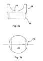
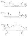
- Implant 20 includes first and second forked ends 22 and 24, each defining a saddle 26, 28 respectively.
- the forked ends 22, 24 are mated using an interbody piece 30.
- the first forked end 22 includes a threaded shaft 32 which projects rearwardly from the saddle 26.
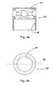
- the threaded shaft 32 fits into the threaded bore 34 (Fig. 4a) of the interbody piece 30.
- the second forked end 24 (Figs. 5a, 5b) includes a smooth cylindrical shaft 36 which can fit into the smooth bore 38 of the interbody piece 30.
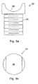
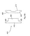
- Fig. 1 shows the implant 20 in a fully extended position
- Fig. 2 shows the implant in an unextended position.
- the threaded shaft 32 of the first forked end 22 fits inside the hollow cylindrical shaft 36 of the second forked end 24.
- the implant 20 For purposes of implantation between adjacent first and second spinous processes of the spinal column, the implant 20 is configured as shown in Fig. 2.
- the first and second spinous processes are exposed using appropriate surgical techniques and thereafter, the implant 20 is positioned so that saddle 26 engages the first spinous process, and saddle 28 engages the second spinous process.
- the interbody piece 30 can be rotated by placing an appropriate tool or pin into the cross holes 40 and upon rotation, the saddle 26 is moved relative to the saddle 28.
- Such rotation spreads apart or distracts the spinous processes with the resultant and beneficial effect of enlarging the volume of the spinal canal in order to alleviate any restrictions on blood vessels and nerves.
- this implant as well as the several other implants described herein act as an extension stop. That means that as the back is bent backwardly and thereby placed in extension the spacing between adjacent spinous processes cannot be reduced to a distance less than the distance between the lowest point of saddle 26 and the lowest point of saddle 28.
- This implant does not inhibit or in any way limit the flexion of the spinal column, wherein the spinal column is bent forward.
- such a device provides for distraction in the range of about 5mm to about 15mm.
- devices which can distract up to and above 22mm may be used depending on the characteristics of the individual patient.
- the implant 20 can be implanted essentially floating in position in order to gain the benefits of the aforementioned extension stop and flexion non-inhibitor.
- one of the saddles 26 can be laterally pinned with pin 29 to one of the spinous processes and the other saddle can be loosely associated with the other spinous processes by using a tether 31 which either pierces or surrounds the other spinous process and then is attached to the saddle in order to position the saddle relative to the spinous process.
- both saddles can be loosely tethered to the adjacent spinous process in order to allow the saddles to move relative to the spinous processes.
- the shape of the saddles being concave, gives the advantage of distributing the forces between the saddle and the respective spinous process. This ensures that the bone is not resorbed due to the placement of the implant 20 and that the structural integrity of the bone is maintained.
- the implant 20 can be made of a number of materials, including but not limited to, stainless steel, titanium, ceramics, plastics, elastics, composite materials or any combination of the above.
- the modulus of elasticity of the implant can be matched to that of bone, so that the implant 20 is not too rigid.
- the flexibility of the implant can further be enhanced by providing additional apertures or perforations throughout the implant in addition to the holes 40 which also have the above stated purpose of allowing the interbody piece 30 to be rotated in order to expand the distance between the saddle 26, 28.
- the spinous processes can be accessed and distracted initially using appropriate instrumentation, and that the implant 20 can be inserted and adjusted in order to maintain and achieve the desired distraction.
- the spinous process can be accessed and the implant 20 appropriately positioned. Once positioned, the length of the implant can be adjusted in order to distract the spinous processes or extend the distraction of already distracted spinous processes.
- the implant can be used to create a distraction or to maintain a distraction which has already been created.
- implant 20 placement of implants such as implant 20 relative to the spinous process will be discussed hereinbelow with other embodiments. However, it is to be noted that ideally, the implant 20 would be placed close to the instantaneous axis of rotation of the spinal column so that the forces placed on the implant 20 and the forces that the implant 20 places on the spinal column are minimized.
- the method uses the approach of extending the length of the implant 20 a first amount and then allowing the spine to creep or adjust to this distraction. Thereafter, implant 20 would be lengthened another amount, followed by a period where the spine is allowed to creep or adjust to this new level of distraction. This process could be repeated until the desired amount of distraction has been accomplished.
- This same method can be used with insertion tools prior to the installation of an implant. The tools can be used to obtain the desired distraction using a series of spinal distraction and spine creep periods before an implant is installed.
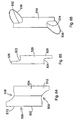
- the apparatus shown in the above Figs. 6, 7, 8, 9 and 10 includes distraction or spreader tool 50 which has first and second arms 52, 54. Arms 52, 54 are pivotal about pivot point 56 and releaseable from pivot point 56 in order to effect the implantation of implant 58. As can be seen in Fig. 6, in cross-section, the arms 52, 54 are somewhat concave in order to cradle and securely hold the first spinous process 60 relative to arm 52 and the second spinous process 62 relative to arm 54.
- the distraction tool 50 can be inserted through a small incision in the back of the patient in order to address the space between the first spinous process 60 and the second spinous process 62. Once the tool 50 is appropriately positioned, the arms 52, 54 can be spread apart in order to distract the spinous processes.
- an implant 58 as shown in Figs. 8 and 9, or of a design shown in other of the embodiments of this invention, can be urged between the arms 52, 54 and into position between the spinous processes. After this occurs, the arms 52, 54 can be withdrawn from the spinous processes leaving the implant 58 in place.
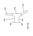
- the implant 58 is urged into place using a tool 64 which can be secured to the implant 58 through a threaded bore 66 in the back of the implant.
- the implant 58 includes saddles 68 and 70 which cradle the upper and lower spinous processes 60, 62 in much the same manner as the above first embodiment and also in much the same manner as the individual arms of the tool 50.
- the saddles as described above tend to distribute the load between the implant and the spinous processes and also assure that the spinous process is stably seated at the lowest point of the respective saddles.
- the spreader or distraction tool 80 includes first and second arms 82, 84 which are permanently pivoted at pivot point 86.
- the arms include L-shaped ends 88, 90.
- the L-shaped ends 88, 90 can be inserted between the first and second spinous processes 92, 94.
- the arms 82, 84 can be spread apart in order to distract the spinous processes.
- the implant 96 can then be urged between the spinous processes in order to maintain the distraction.
- implant 96 includes wedged surfaces or ramps 98, 100. As the implant 96 is being urged between the spinous processes, the ramps further cause the spinous processes to be distracted.
- the implant 96 Once the implant 96 is fully implanted, the full distraction is maintained by the planar surfaces 99, 101 located rearwardly of the ramps. It is to be understood that the cross-section of the implant 96 can be similar to that shown for implant 58 or similar to other implants in order to gain the advantages of load distribution and stability.
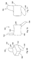
- This implant 110 includes first and second conically shaped members 112, 114.
- Member 112 includes a male snap connector 116 and member 114 includes a female snap connector 118. With male snap connector 116 urged into female snap connector 118, the first member 112 is locked to the second member 114.
- a distraction or spreader tool 80 could be used.
- an implantation tool 120 can be used to position and snap together the implant 110.
- the first member 112 of implant 110 is mounted on one arm and second member 114 is mounted on the other arm of tool 120.
- the member 112, 114 are placed on opposite sides of the space between adjacent spinous processes.
- the members 112, 114 are urged together so that the implant 110 is locked in place between the spinous processes as shown in Fig. 15. It is to be noted that the implant 110 can also be made more self-distracting by causing the cylindrical surface 122 to be more conical, much as surface 124 is conical, in order to hold implant 110 in place relative to the spinous processes and also to create additional distraction.
- This implant 130 includes first and second members 132, 134.
- the implants are held together using a screw (not shown) which is inserted through countersunk bore 136 and engages a threaded bore 138 of the second member 134.
- Surfaces 139 are flattened (Fig. 17) in order to carry and spread the load applied thereto by the spinous processes.
- the implant 130 is not circular in overall outside appearance, as is the embodiment 110 of Figs. 14 and 15.
- this implant is truncated so that the lateral side 140, 142 are flattened with the upper and lower sides 144, 146 being elongated in order to capture and create a saddle for the upper and lower spinous processes.
- the upper and lower sides, 144, 146 are rounded to provide a more anatomical implant which is compatible with the spinous processes.
- key 148 and keyway 150 are designed to mate in a particular manner.
- Key 148 includes at least one flattened surface, such as flattened surface 152, which mates to an appropriately flattened surface 154 of the keyway 150.
- the first member is appropriately mated to the second member in order to form appropriate upper and lower saddles holding the implant 130 relative to the upper and lower spinous processes.
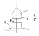
- Fig. 16a depicts second member 134 in combination with a rounded nose lead-in plug 135.
- Lead-in plug 135 includes a bore 137 which can fit snugly over key 148. In this configuration, the lead-in plug 135 can be used to assist in the placement of the second member 134 between spinous processes. Once the second member 134 is appropriately positioned, the lead-in plug 135 can be removed. It is to be understood that the lead-in plug 135 can have other shapes such as pyramids and cones to assist in urging apart the spinous processes and soft tissues in order to position the second member 134.
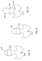
- the implant 330 as shown in Fig. 18 is comprised of first and second mating wedges 332 and 334.
- the spinous processes are accessed from both sides and then a tool is used to push the wedges towards each other.
- the wedges move relative to each other so that the combined dimension of the implant 330 located between the upper and lower spinous processes 336, 338 (Fig. 20), increases, thereby distracting the spinous processes.
- the wedges 332, 334 include saddle 340, 342, which receiving the spinous processes 336, 338. These saddles have the advantages as described hereinabove.
- the first or second wedges 332, 334 have a mating arrangement which includes a channel 344 and a projection of 346 which can be urged into the channel in order to lock the wedges 332, 334 together.
- the channel 334 is undercut in order to keep the projection from separating therefrom .
- a detent can be located in one of the channel and the projection, with a complimentary recess in the other of the channel and the projection. Once these two snap together, the wedges are prevented from sliding relative to the other in the channel 344.
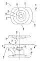
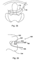
- the implant 370 is comprised of first and second distraction cone 372, 374. These cones are made of a flexible material. The cones are positioned on either side of the spinous processes 376, 378 as shown in Fig. 21. Using appropriate tool as shown hereinabove, the distraction cones 372, 374 are urged together. As they are urged together, the cones distract the spinous processes as shown in Fig. 22. Once this has occurred, an appropriate screw or other type of fastening mechanism 380 can be used to maintain the position of the distraction cones 372, 374.
- the advantage of this arrangement is that the implant 370 is self-distracting and also that the implant, being flexible, molds about the spinous processes as shown in Fig. 22.
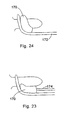
- FIGs. 23 and 24 another implant 170 is depicted.
- This implant is guided in place using an L-shaped guide 172 which can have a concave cross-section such as the cross-section 52 of retraction tool 50 in Fig. 6 in order to cradle and guide the implant 170 in position.
- a small incision would be made into the back of the patient and the L-shaped guide tool 172 inserted between the adjacent spinous processes.
- the implant 170 would be mounted on the end of insertion tool 174 and urged into position between the spinous processes. The act of urging the implant into position could cause the spinous processes to be further distracted if that is required.
- a distraction tool such as shown in Fig. 13 could be used to initially distract the spinous processes.
- Implant 170 can be made of a deformable material so that it can be urged into place and so that it can somewhat conform to the shape of the upper and lower spinous processes.
- This deformable material would be preferably an elastic material. The advantage of such a material would be that the load forces between the implant and the spinous processes would be distributed over a much broader surface area. Further, the implant would mold itself to an irregular spinous process shape in order to locate the implant relative to spinous processes.
- this implant 176 can be inserted over a guide wire, guide tool or stylet 178.
- the guide wire 178 is positioned through a small incision to the back of the patient to a position between the adjacent spinous processes.
- the implant is threaded over the guide wire 178 and urged into position between the spinous processes. This urging can further distract the spinous processes if further distraction is required.
- the guide tool 178 is removed and the incision closed.
- the insertion tools of Figs. 23 and 24 can also be used if desired.
- FIGs. 26, 27 and 28 uses an implant similar to that depicted in Figs. 8 and 9 with different insertion tools.
- an L-shaped distraction tool 190 is similar to L-shaped distraction tool 80 (Fig. 12), is used to distract the first and second spinous processes 192, 194.
- an insertion tool 196 is placed between the spinous processes 192, 194.
- Insertion tool 196 includes a handle 198 to which is mounted a square-shaped ring 200.
- the distraction tool 190 can be inserted through a small incision in the back in order to spread apart the spinous processes.
- an upper end 202 of ring 200 can be initially inserted followed by the remainder of the ring 200.
- the ring can be rotated slightly by moving handle 198 downwardly in order to further wedge the spinous processes apart.
- an implant such as implant 204 can be inserted through the ring and properly positioned using implant handle 206. Thereafter, the implant handle 206 and the insertion tool 196 can be removed.
- the implants 210, 212 can have different shapes when viewed from the side. These implants are similar to the above-referenced implants 58 (Fig. 8) and 204 (Fig. 28). These implants have cross-sections similar to that shown in Fig. 10 which includes saddles in order to receive and hold the adjacent spinous processes.
- these implants can be placed in different positions with respect to the spinous process 214.
- the implant 210 is placed closest to the lamina 216. Being so positioned, the implant 210 is close to the instantaneous axis of rotation 218 of the spinal column, and the implant would experience least forces caused by-movement of the spine. Thus, theoretically, this is the optimal location for the implant.
- the implant can be placed midway along the spinous process (Fig, 32) and towards the posterior aspect of the spinous process (Fig. 31). As positioned shown in Fig. 31, the greatest force would be placed on the implant 210 due to a combination of compression and extension of the spinal column.
- implant 220 is comprised of a plurality of individual leaves 222 which are substantially V-shaped.
- the leaves include interlocking indentations or detents 224. That is, each leaf includes an indentation with a corresponding protrusion such that a protrusion of one leaf mates with an indentation of an adjacent leaf.
- an insertion tool 226 which has a blunt end 228 which conforms to the shape of an individual leaf 222. For insertion of this implant into the space between the spinous processes as shown in Fig. 29, the insertion tool 226 first insert a single leaf 220.
- the insertion tool then inserts a second leaf with the protrusion 224 of the second leaf snapping into corresponding indentation made by the protrusion 224 of the first leaf.
- This process would reoccur with third and subsequent leaves until the appropriate spacing between the spinous processes was built up.
- the lateral edges 229 of the individual leaves 222 are slightly curved upwardly in order to form a saddle for receiving the upper and lower spinous processes.
- Implant 220 is essentially a series of truncated cones and includes a plurality of ever expanding steps 236. These steps are formed by the conical bodies starting with the nose body 238 followed there behind by conical body 240. Essentially, the implant 234 looks like a fir tree placed on its side.
- the implant 230 is inserted laterally throughout the opening between upper and lower spinous processes.
- the first body 238 causes the initial distraction. Each successive conical body distracts the spinous processes a further incremental amount.
- the spinous processes are locked into position by steps 236.
- the initial nose body 238 of the implant and other bodies 240 can be broken, snapped or sawed off if desired in order to minimize the size of the implant 230.
- the intersection between bodies such as body 238 and 240 which is intersection line 242
- intersection line 244 between the bodies which remain between the spinous processes would not need to be weaker, as there would be no intention that the implant would be broken off at this point.
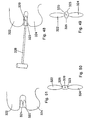
- Fig. 37 shows implant 232 positioned between upper and lower spinous processes.
- This implant is wedge-shaped or triangular shaped in cross-sectioned and includes bore pluralities 245 and 246. Through these bores can be placed locking pins 248 and 250. The triangular or wedged-shaped implant can be urged laterally between and thus distract the upper and lower spinous processes. Once the appropriate distraction is reached, pins 248, 250 can be inserted through the appropriate bores of the bore pluralities 245 and 246 in order to lock the spinous processes in a V-shaped valley formed by pins 248, 250 on the one hand and the ramped surface 233, 235 on the other hand.
- the implant 234 has a triangular-shaped or wedge-shaped body similar to that shown in Fig. 32.
- tab 252, 254 are pivotally mounted to the triangular shaped body 234. Once the implant 234 is appropriately positioned in order to distract the spinous processes to the desired amount, the tabs 252, 254 rotate into position in order to hold the implant 234 in the appropriate position.
- cannula 258 is inserted through a small incision to a position between upper and lower spinous processes.
- an implant 260 is pushed through the cannula 258 using an insertion tool 262.
- the implant 260 includes a plurality of ribs or indentation 264 that assist in positioning the implant 260 relative to the upper and lower spinal processes.
- the cannula 258 is withdrawn so that the implant 260 comes in contact with and wedges between the spinous processes.
- the cannula 258 is somewhat conical in shape with the nose end 266 being somewhat smaller than the distal end 268 in order to effect the insertion of the cannula into the space between the spinous processes.
- a plurality of cannula can be used instead of one, with each cannula being slightly bigger than one before.
- the first smaller cannula would be inserted followed by successively larger cannula being placed over the previous smaller cannula.
- the smaller cannula would then be withdrawn from the center of the larger cannula. Once the largest cannula is in place, and the opening of the skin accordingly expanded, the implant, which is accommodated by only the larger cannula, is inserted through the larger cannula and into position.
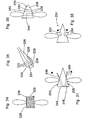
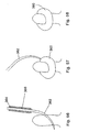
- the precurved implant 270 in Figs. 41 and 42, and precurved implant 272 in Fig. 43 have common introduction techniques which includes a guide wire, guide tool, or stylet 274.
- the guide wire 274 is appropriately positioned through the skin of the patient and into the space between the spinous processes. After this is accomplished, the implant is directed over the guide wire and into position between the spinous processes.
- the precurved nature of the implant assist in (1) positioning the implant through a first small incision in the patient's skin on one side of the space between two spinous processes and (2) guiding the implant toward a second small incision in the patient's skin on the other side of the space between the two spinous processes.
- the implant includes a conical introduction nose 276 and a distal portion 278. As the nose 276 is inserted between the spinous processes, this causes distraction of the spinous processes. Break lines 280, 282 are established at opposite sides of the implant 270. Once the implant is properly positioned over the guide wire between the spinous processes, the nose portion 276 and the distal portion 278 can be broken off along the break lines, through the above two incisions, in order to leave the implant 270 in position.
- break lines 280, 282 can be provided on implant 270 so that the implant can continue to be fed over the guide wire 278 until the appropriate width of the implant 270 creates the desired amount of distraction.
- the break lines can be created by perforating or otherwise weakening the implant 270 so that the appropriate portions can be snapped or sawed off.
- this implant is similar in design to the implant 230 shown in Fig. 36.
- This implant 272 in Fig. 47 is precurved and inserted over a guide wire 274 to a position between the spinous processes.
- sections of the implant 272 can be broken, snapped or sawed off as described hereinabove in order to leave a portion of the implant wedged between the upper and lower spinous processes.
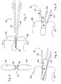
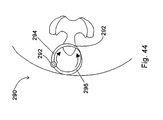
- the apparatus of Fig. 44 includes a combination insertion tool and implant 290.
- the insertion tool and implant 290 is in the shape of a ring which is hinged at point 292.
- the ring is formed by a first elongated and conically shaped member 294 and a second elongated and conically shaped member 296.
- Members 294 and 296 terminate in points and through the use of hinge 292 are aligned and meet.
- first member and second member are inserted through the skins of the patient and are mated together between the spinous processes. After this has occurred, the implant 290 is rotated, for example clockwise, so that increasingly widening portions of the first member 292 are used to distract the first and second spinous processes.
- the remainder of the ring before and after the section which is located between the spinous processes can be broken off as taught hereinabove in order to maintain the desired distraction.
- the entire ring can be left in place with the spinous processes distracted.
- the implant 300 is comprised of a plurality of rods or stylets 302 which are inserted between the upper and lower spinous processes.
- the rods are designed much as described hereinabove so that they may be broken, snapped or cut off. Once these are inserted and the appropriate distraction has been reached, the stylets are broken off and a segment of each stylet remains in order to maintain distraction of the spinous process.
- Implant 310 of Figs. 46 and 47 is comprised of a shape memory material which coils upon being released.
- the material is straightened out in a delivery tool 312.
- the delivery tool is in position between upper and lower spinous processes 314, 316.
- the material is then pushed through the delivery tool.
- the material coils, distracting the spinous processes to the desired amount. Once this distraction has been achieved, the material is cut and the delivery tool removed.
- the implant 320 is delivered between upper and lower spinous processes 322 and 324, by delivery tool 326.
- the delivery tool is given a 90° twist so that the implant goes from the orientation as shown in Fig. 49, with longest dimension substantially perpendicular to the spinous processes, to the orientation shown in Fig. 50 where the longest dimension is in line with and parallel to the spinous processes.
- This rotation causes the desired distraction between the spinous processes.
- Implant 320-in cludes opposed recesses 321 and 323 located at the ends thereof. Rotation of the implant 320 causes the spinous processes to become lodged in these recesses.
- the insertion tool 326 can be used to insert multiple implants 320, 321 into the space between the spinous processes 322, 324 (Fig. 51). Multiple implants 320, 321 can be inserted until the appropriate amount of distraction is built up. It is to be understood in this situation that one implant would lock to another implant by use of, for example, a channel arrangement wherein a projection from one of the implants would be received into and locked into a channel of the other implant. Such a channel arrangement is depicted with respect to the other embodiment.
- the apparatus of Figs. 52 through 55b is comprised of a fluid-filled dynamic distraction implant 350.
- This implant includes a membrane 352 which is placed over pre-bent insertion rod 354 and then inserted through an incision on one side of the spinous process 356.
- the bent insertion rod, with the implant 350 thereover, is guided between appropriate spinous processes. After this occurs, the insertion rod 354 is removed leaving the flexible implant in place.
- the implant 350 is then connected to a source of fluid (gas, liquid, gel and the like) and the fluid is forced into the implant causing it to expand as shown in Fig. 54, distracting the spinal processes to the desired amount.
- the implant 350 is closed off as is shown in Fig. 55a.
- the implant 350 being flexible, can mold to the spinous processes which may be of irregular shape, thus assuring positioning. Further, implant 350 acts as a shock absorber, damping forces and stresses between the implant and the spinous processes.
- a variety of materials can be used to make the implant and the fluid which is forced into the implant.
- viscoelastic substances such as methylcellulose, or hyaluronic acid can be used to fill the implant.
- materials which are initially a fluid, but later solidify can be inserted in order to cause the necessary distraction. As the materials solidify, they mold into a custom shape about the spinous processes and accordingly are held in position at least with respect to one of two adjacent spinous processes.
- the implant can be formed about one spinous process in such a manner that the implant stays positioned with respect to that spinous process (Fig. 55b).
- a single implant can be used as an extension stop for spinous process located on either side, without restricting flexion of the spinal column.
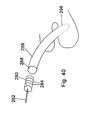
- the implant 360 as shown in Fig. 56 is comprised of a shape memory material such as a plastic or a metal.
- a curved introductory tool 362 is positioned between the appropriate spinous processes as described hereinabove. Once this has occurred, bore 364 of the implant is received over the tool. This act can cause the implant to straighten out. The implant is then urged into position and thereby distracts the spinous processes. When this has occurred, the insertion tool 362 is removed, allowing the implant to assume its pre-straightened configuration and is thereby secured about one of the spinous processes.
- the implant can be temperature sensitive. That is to say that the implant would be more straightened initially, but become more curved when it was warmed by the temperature of the patient's body.
- the implant 380 is comprised of a plurality of interlocking leaves 382. Initially, a first leaf is positioned between opposed spinous processes 384, 386. Then subsequently, leafs 382 are interposed between the spinous processes until the desired distraction has been built up. The leaves are somewhat spring-like in order to absorb the shock and can somewhat conform to the spinous processes.
- the implant 390 of Fig. 61 includes the placement of shields 392, 394 over adjacent spinous processes 396, 398.
- the shields are used to prevent damage to the spinous processes.
- These shields include apertures which receives a self-tapping screw 400, 402.
- the shields are affixed to the spinous processes and the spinous processes are distracted in the appropriate amount. Once this has occurred, a rod 404 is used to hold the distracted position by being screwed into each of the spinous processes through the aperture in the shields using the screws as depicted in Fig. 61.
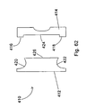
- Implant 410 of Figs. 62, 63 is comprised of first and second members 412, 414 which can be mated together using an appropriate screw and threaded bore arrangement to form the implant 410.
- Main member 412 and mating member 414 form implant 410.
- the implant 410 would have a plurality of members 414 for use with a standardized first member 412.
- Figs. 62 and 64 show different types of mating members 414.
- the mating member 414 includes projections 416 and 418 which act like shims. These projections are used to project into the space of saddles 420, 422 of the first member 412. These projections 416, 418 can be of varying lengths in order to accommodate different sizes of spinous processes.
- a groove 424 is placed between the projections 416, 418 and mates with an extension 426 of the first member 412.
- Figs. 64, 65 and 66 are similar in design and concept to the embodiment of Figs. 62 and 63.
- the implant 500 includes the first and second members 502, 504. These members can be secured together with appropriate screws or other fastening means as taught in other implants.
- Implant 500 includes first and second saddles 506, 508 which are formed between the ends of first and second members 502, 504. These saddles 506, 508 are used to receive and cradle the adjacent spinous processes. As can be seen in Fig. 64, each saddle 506, 508 is defined by a single projection or leg 510, 512, which extends from the appropriate first and second members 502, 504. Unlike the implant found in Figs.
- each of the saddles is defined by only a single leg as the ligaments and other tissues associated with the spinous processes can be used to ensure that the implant is held in an appropriate position.
- Fig. 64 it is easier to position the implant relative to the spinous processes as each saddle is defined by only a single leg and thus the first and second members can be more easily worked into position between the various tissues.
- the implant 520 is comprised of a single piece having saddles 522 and 524.
- the saddles are defined by a single leg 526, 528 respectively.
- an incision is made between lateral sides of adjacent spinous processes.
- the single leg 526 is directed through the incision to a position adjacent to an opposite lateral side of the spinous process with the spinous process cradled in the saddle 522.
- the spinous processes are then urged apart until saddle 524 can be pivoted into position into engagement with the other spinous process in order to maintain the distraction between the two adjacent spinous processes.
- the implant of Fig. 66 is similar to that of Fig. 65 with an implant 530 and first and second saddles 532 and 534. Associated with each saddle is a tether 536, 538 respectively.
- the tethers are made of flexible materials known in the trade and industry and are positioned through bores in the implant 530. Once appropriately positioned, the tethers can be tied off. It is to be understood that the tethers are not meant to be used to immobilize one spinous process relative to the other, but are used to guide motion of the spinous processes relative to each other so that the implant 530 can be used as an extension stop and a flexion non-inhibitor.
- the saddles 532, 534 are used to stop spinal column backward bending and extension. However, the tethers do not inhibit forward bending and spinal column flexion.
- the implant 550 is Z-shaped and includes a central body 552 and first and second arms 554, 556, extending in opposite directions therefrom.
- the central body 552 of the implant 550 includes first and second saddles 558 and 560.
- the first and second saddles 558 and 560 would receive upper and lower spinous processes 562, 568.
- the arms 554, 556 are accordingly located adjacent the distal end 566 (Fig. 68) of the central body 552.
- the first and second arms 554, 556 act to inhibit forward movement, migration or slippage of the implant 550 toward the spinal canal and keep the implant in place relative to the first and second spinal processes. This prevents the implant from pressing down on the ligamentum flavum and the dura.
- the central body would have a height of about 10mm with each of the arms 554, 556 have a height of also about 10mm. Depending on the patient, the height of the body could' vary from about less than 10mm to about greater than 24mm.
- the first and second arms 554, 556 are additionally contoured in order to accept the upper and lower spinous processes 556, 558.
- the arms 554, 556 as can be seen with respect to arm 554 have a slightly outwardly bowed portion 568 (Fig. 68) with a distal end 570 which is slightly inwardly bowed.
- This configuration allows the arm to fit about the spinous process with the distal end 570 somewhat urged against the spinous process in order to guide the motion of the spinous process relative to the implant.
- These arms 554, 556 could if desired to be made more flexible than the central body 552 by making arms 554, 556 thin and/or with perforations, and/or other material different than that of the central body 550.
- this implant can be urged into position between adjacent spinous processes by directing an arm into a lateral incision so that the central body 552 can be finally positioned between spinous processes.
- Figs. 69, 70 and 71 are perspective front, end, and side views of an implant 580.
- This implant includes a central body 582 which has first and second saddles 584, 586 for receiving adjacent spinous processes. Additionally, the implant 580 includes first and second arms 588 and 590. The arms, as with the past embodiment, prevent forward migration or slippage of the implant toward the spinal canal.
- First arm 588 projects outwardly from the first saddle 584 and second arm 590 projects outwardly from the second saddle 586.
- the first arm 588 is located adjacent to the distal end 600 of the central body 582 and proceeds only partly along the length of the central body 582.
- the first arm 588 is substantially perpendicular to the central body as shown in Fig. 70. Further, the first arm 588, as well as the second arm 590, is anatomically rounded.
- the second arm 590 projecting from second saddle 586, is located somewhat rearward of the distal end 600, and extends partially along the length of the central body 582.
- the second arm 590 projects at a compound angle from the central body 582.
- the second arm 590 is shown to be at about an angle of 45° from the saddle 586 (Fig. 70). Additionally, the second arm 590 is at an angle of about 45° relative to the length of the central body 580 as shown in Fig. 71. It is to be understood that other compound angles are possible.
- first and second arms 588, 590 have a length which is about the same as the width of the central body 582.
- the length of each arm is about 10mm and the width of the central body is about 10mm.
- the bodies with the widths of 24mm and greater are within the spirit and scope of the invention, along with first and second arms ranging from about 10mm to greater than about 24mm.
- the embodiment could include a central body having a width of about or greater than 24mm with arms being at about 10mm.
- the implant of Figs. 69, 70 and 71 as well as the implant of Figs. 67 and 68 are designed to preferably be positioned between the L4-L5 and the L5-S1 vertebral pairs.
- the implant of Figs. 69, 70, 71 is particularly designed for the L5-S1 position with the arms being designed to conform to the sloping surfaces found therebetween. The first and second arms are thus contoured so that they lie flat against the lamina of the vertebra which has a slight angle.
- the implant of Fig. 69, 70, and 71 as with the implant of Figs. 67 and 68 is Z-shaped in configuration so that it may be inserted from one lateral side to a position between adjacent spinous processes. A first arm, followed by the central body, is guided through the space between the spinous processes. Such an arrangement only requires that a incision on one side of the spinous process be made in order to successfully implant the device between the two spinous processes.
- the implant 610 of Fig. 71 a is similar to that immediately above with the first arm 612 located on the same side of the implant as the second arm 614.
- the first and second saddle 616, 618 are slightly modified in that distal portion 620, 622 are somewhat flattened from the normal saddle shape in order to allow the implant to be positioned between the spinous processes from one side. Once in position, the ligaments and tissues associated with the spinous processes would hold the implant into position. Tethers also could be used if desired.
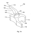
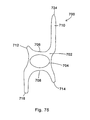
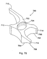
- Implant 630 is also designed so that it can be inserted from one side of adjacent spinous processes.
- This insert 630 includes a central body 632 with the first and second arms 634, 636 extending on either side thereof.
- a plunger 638 is positioned to extend from an end of the central body 632.
- the plunger 638 is fully extended and as shown in Fig. 73, the plunger 638 is received within the central body 632 of the implant 630.
- the third and fourth arms or hooks 640, 642 can extend outwardly from the central body 632.
- the third and fourth arms or hooks 640, 642 can be comprised of a variety of materials, such as for example, shape memory metal materials or materials which have a springy quality.
- the plunger 638 is pulled outwardly as shown in Fig. 72.
- the central body 632 is then positioned between adjacent spinous processes and the plunger 638 is allowed to move to the position of Fig. 73 so that the third and fourth arms 640, 642 can project outwardly from the central body 632 in order to hold the implant 630 in position between the spinous processes.
- Plunger 638 can be spring biased to the position as shown in Fig. 73 or can include detents or other mechanisms which lock it into that position. Further, the third and fourth arms themselves, as deployed, can keep the plunger in the position as shown in Fig. 73.
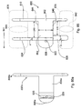
- Implant 700 is particularly suited for implantation between the L4-L5 and L5-S1 vertebra.
- the implant 700 includes a central body 702 which has a bore 704 provided therein. Bore 704 is used in order to adjust the modulus of elasticity of the implant so that it is preferably approximately two times the anatomical load placed on the vertebra in extension. In other words, the implant 700 is approximately two times stiffer than the normal load placed on the implant.
- Such an arrangement is made in order to ensure that the implant is somewhat flexible in order to reduce potential resorption of the bone adjacent to the implant.
- Other modulus values can be used and be within the spirit of the invention.
- Implant 700 includes first and second saddle 706, 708 which are used to receive and spread the load from the upper and lower spinous processes.
- the saddle 706 is defined by first and second arms 710 and 712.
- the second saddle 708 is defined by third and fourth arms 714 and 716.
- the first arm 710 in a preferred implant, is approximately two times the length of the body 702 with the second arm being approximately less than a quarter length of the body.
- Third arm 714 is approximately one times the length of the body 702 with the fourth arm 716 being, in this preferred implant, approximately one and a half times the length of the body 702.
- the arms are designed in such a way that the implant (1) can be easily and conveniently inserted between the adjacent spinous processes, (2) will not migrate forwardly toward the spinal canal, and (3) will hold its position through flexion and extension as well as lateral bending of the spinal column.
- First arm 710 is in addition designed to accommodate the shape of the vertebra. As can be seen in Fig. 74, the first arm 710 becomes narrower as it extends away from the body 702.
- the first arm 710 includes a sloping portion 718 followed by a small recess 720 ending in a rounded portion 722 adjacent to the end 724.
- This design is provided to accommodate the anatomical form of for example the L4 vertebra. It is to be understood that these vertebra have a number of surfaces at roughly 30° angles and that the sloping surfaces of this implant and the implants shown in Figs. 77 and 78 are designed to accommodate these surfaces. These implants can be further modified in order to accommodate other angles and shapes.
- the second arm 712 is small so that it is easy to insert between the spinous processes, yet still define the saddle 706.
- the fourth arm 716 is larger than the third arm 714, both of which are smaller than the first arm 710.
- the third and fourth arms are designed so that they define the saddle 706, guide the spinous processes relative to the implant 700 during movement of the spinal column, and yet are of a size which makes the implant easy to position between the spinous processes.
- the procedure, by way of example only, for implanting the implant 700 can be to make an incision laterally between two spinous processes and then initially insert first arm 710 between the spinous processes.
- the implant and/or appropriate tools would be used to distract the spinous processes allowing the third leg 714 and the central body 702 to fit through the space between the spinous processes.
- the third leg 714 would then come to rest adjacent the lower spinous processes on the opposite side with the spinous processes resting in the first and second saddle 706, 708.
- the longer fourth leg 716 would then assist in the positioning of the implant 700.
- Fig. 77 includes an implant 740 which is similar to implant 700 and thus have similar numbering.
- the saddle 706, 708 of implant 740 have been cantered or sloped in order to accommodate the bone structure between, by way of example, the L4-L5 and the L5-S1 vertebra.
- the vertebra in this area have a number of sloping surfaces in the range of about 30°. Accordingly, saddle 706 is sloped at less than 30° and preferably about 20° while saddle 708 is sloped at about 30° and preferably more than 30°.
- Implant 760 as shown in Fig. 78 is similar to implant 700 in Fig. 74 and is similarly numbered.
- Implant 760 includes third and fourth legs 714, 716 which have sloping portions 762, 764 which slope toward ends 766, 768 of third and fourth arm 714, 716 respectively.
- the sloping portions accommodate the form of the lower vertebra against which they are positioned. In the preferred embodiment, the sloping portions are of about 30°. However, it is to be understood that sloping portions which are substantially greater and substantially less than 30° can be included and be within the spirit and scope of the invention.
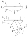
- Implant 800 includes a distracting unit 802 which is shown in left side, plan, and right side views of Figs. 79, 80 and 81.
- a perspective view of the distraction unit is shown in Fig. 84.
- the distracting unit as can be seen in Fig. 80 includes a distracting body 804, with longitudinal axis 805, which body 804 has a groove 806 and a rounded or bulbous end 808 which assist in the placement of the distracting body between adjacent spinous process so that an appropriate amount of distraction can be accomplished.
- Extending from the distracting body 804 is a first wing 810 which in Fig. 80 is substantially perpendicular to the distracting body 804.
- First wing 810 includes a upper portion 812 and a lower portion 814.
- the upper portion 810 (Figs. 79) includes a rounded end 816 and a small recess 818.
- the rounded end 816 and the small recess 818 in the preferred embodiment are designed to accommodate the anatomical form or contour of the L4 (for a L4-L5 placement) or L5 (for a L5-S1 placement) superior lamina of the vertebra. It is to be understood that the same shape or variations of this shape can be used to accommodate other lamina of any vertebra.
- the lower portion 814 is also rounded in order to accommodate in the preferred embodiment in order to accommodate the vertebrae.
- the distracting unit further includes a threaded bore 820 which in this embodiment accepts a set screw 822 (Fig. 86) in order to hold a second wing 824 (Figs. 82, 83) in position as will be discussed hereinbelow.
- the threaded bore 820 in this embodiment slopes at approximately 45° angle and intersects the slot 806. With the second wing 824 in position, the set screw 822 when it is positioned in the threaded bore 820 can engage and hold the second wing 824 in position in the slot 806.
- the second wing 824 is similar in design to the first wing.
- the second wing includes an upper portion 826 and a lower portion 828.
- the upper portion includes a rounded end 830 and a small recess 832.
- the second wing 824 includes a slot 834 which mates with the slot 806 of the distracting unit 802.
- the second wing 824 is the retaining unit of the present embodiment.
- the second wing or retaining unit 824 includes the upper portion 826 having a first width "a" and the lower portion 828 having a second width "b".
- the second width "b" is larger than first width "a” due to the anatomical form or contour of the L4-L5 or L5-S1 laminae.
- the widths "a" and “b” would be increased in order to, as described hereinbelow, accommodate spinous processes and other anatomical forms or contours which are of different dimensions. Further, as appropriate, width "a" can be larger than width "b".
- the implant can include a universally-shaped distracting unit 802 with a plurality of retaining units 824, with each of the retaining units having different widths "a” and "b".
- the appropriately sized retaining unit 824, width with the appropriate dimensions "a” and “b” can be selected to match to the anatomical form of the patient.
- Fig. 86 depicts an assembled implant 800 positioned adjacent to upper and lower laminae 836, 838 (which are shown in dotted lines) of the upper and lower vertebrae.
- the vertebrae 836, 838 are essentially below the implant 800 as shown in Fig. 86.
- the fit of the implant between the spinous processes can be such that the wings do not touch the spinous processes, as shown in Fig. 86, and be within the scope of the invention.
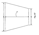
- the implant 800 includes, as assembled, an upper saddle 844 and the lower saddle 846.
- the upper saddle 844 has an upper width identified by the dimension "UW”.
- the lower saddle 846 has a lower width identified by the dimension "LW”.
- the upper width is greater than the lower width.
- the "UW” can be smaller than the "LW” depending on the anatomical requirements.
- the height between the upper and lower saddles 844, 846 is identified by the letter “h”.
- the patient is preferably positioned on his side (arrow 841 points up from an operating table) and placed in a flexed (tucked) position in order to distract the upper and lower vertebrae.
- a small incision is made on the midline of the spinous processes.
- the spinous processes are spread apart or distracted with a spreader.
- the incision is spread downwardly toward the table, and the distracting unit 802 is preferably inserted upwardly between the spinous processes 840 and 842 in a manner that maintains the distraction of spinous processes.
- the distracting unit 802 is urged upwardly until the distracting or bulbous end 808 and the slot 806 are visible on the other side of the spinous process. Once this is visible, the incision is spread upwardly away from the table and the retaining unit or second wing 824 is inserted into the slot 806 and the screw 822 is used to secure the second wing in position. After this had occurred, the incisions can be closed.
- An alternative surgical approach requires that small incisions be made on either side of the space located between the spinous processes.
- the spinous processes are spread apart or distracted using a spreader placed through the upper incision.
- the distracting unit 802 is preferably inserted upwardly between the spinous processes 840 and 842 in a manner that urges the spinous processes apart.
- the distracting unit 802 is urged upwardly until the distracting or bulbous end 808 and the slot 806 are visible through the second small incision in the patient's back. Once this is visible, the retaining unit or second wing 824 is inserted into the slot 806 and the screw 822 is used to secure the second wing in position. After this has occurred, the incisions can be closed.
- Fig. 80a shows an alternative embodiment of the distracting unit 802a.
- This distracting unit 802a is similar to distracting unit 802 in Fig. 80 with the exception that the bulbous end 808a is removable from the rest of the distracting body 804a as it is screwed into the threaded bore 809. The bulbous end 808a is removed once the distracting unit 802a is positioned in the patient in accordance with the description associated with Fig. 86.
- the bulbous end 808a can extend past the threaded bore 820 by about 1 cm in a preferred embodiment.
- FIG. 88, 89, 90 and 91 Another embodiment of the invention is shown in Figs. 88, 89, 90 and 91.
- the implant is identified by the number 900.
- Other elements of implant 900 which are similar to implant 800 are similarly numbered but in the 900 series.
- the distracting unit is identified by the number 902 and this is in parallel with the distracting unit 802 of the implant 800.
- the distracting body is identified by the number 904 in parallel with the distracting body 804 of the implant 800. Focusing on Fig. 90, the distracting unit 902 is depicted in a perspective view.
- the distracting unit includes slot 906 which is wider at the top than at the bottom. The reason for this is that the wider upper portion of the slot 906, which is wider than the second wing 924 (Fig.
- the end 908 of implant 900 is different in that it is more pointed, having sides 909 and 911 which are provided at about 45° angles (other angles, such as by way of example only, from about 30° to about 60° are within the spirit of the invention), with a small flat tip 913 so that the body 904 can be more easily urged between the spinous processes.
- the distracting unit 902 further includes a tongue-shaped recess 919 which extends from the slot 906. Located in the tongue-shaped recess is a threaded bore 920.
- a second wing 924 includes a tongue 948 which extends substantially perpendicular thereto and between the upper and lower portions 926, 928.
- the tab 948 includes a bore 950.
- the present invention can be used to relieve pain caused by spinal stenosis in the form of, by way of example only, central canal stenosis or foraminal (lateral) stenosis. These implants have the ability to flatten the natural curvature of the spine and open the neural foramen and the spacing between adjacent vertebra to relieve problems associated with the above-mentioned lateral and central stenosis. Additionally, the invention can be used to relieve pain associated with facet arthropathy. The present invention is minimally invasive and can be used on an outpatient basis.
Abstract
Description
- As the present society ages, it is anticipated that there will be an increase in adverse spinal conditions which are characteristic of older people. By way of example, with aging comes increases in spinal stenosis (including but not limited to central canal and lateral stenosis), the thickening of the bones which make up the spinal column and facet arthropathy. Spinal stenosis is characterized by a reduction in the available space for the passage of blood vessels and nerves. Pain associated with such stenosis can be relieved by medication and/or surgery. Of course, it is desirable to eliminate the need for major surgery for all individuals and in particular for the elderly.
- Accordingly, there needs to be developed procedures and implants for alleviating such condition which are minimally invasive, can be tolerated by the elderly and can be performed preferably on an outpatient basis.
-
US-A-5,496,318 , on which the two-part form of claim 1 is based, discloses a spinal fixation device for the stabilisation of the spine after surgical procedures. In one such device (Figs. 1-3) the device comprises a first unit and a second unit. The first unit comprises a plate having a bar attached to its wider end. The second unit takes the form of a bar, which comprises a hollow section to accommodate the plate of the first unit. The plate is intended to be slid between adjacent spinous processes and then to be received in the hollow section of the bar of the second unit and to be secured thereto by means of a pin. The plate is required to be inserted between the adjacent spinous processes from one side of the spine, and the bar is required to be slid onto the plate of the first unit from the other side of the spine, thereby requiring the surgeon to have good access to both sides of the spinous processes. - According to the present invention there is provided the implant set out in the accompanying claim 1.
- Preferred aspects of the implant are set out in the dependent claim.
- Two embodiments of implant in accordance with the present invention will now be described, by way of example only, with reference to Figures 79-87 and 88-91 of the accompanying drawings. The arrangements illustrated in Figures 1-78 of the drawings are not in accordance with the invention as claimed, but nevertheless contribute to understanding of the present invention.
-
- Figs. 1 and 2 depict an implant which is adjustable in order to select the amount of distraction required. Fig. 1 depicts the implant in a more extended configuration than does Fig. 2.
- Figs. 3a and 3b depict side and end views of a first forked and of the implant of Fig. 1.
- Figs. 4a and 4b depict side sectioned and end views of an interbody piece of the implant of Fig. 1.
- Figs. 5a and 5b depict side and end views of a second forked end of the implant of Fig. 1.
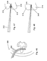
- Figs. 6, 7, 8, 9 and 10 depict apparatus and method for creating distraction between adjacent spinous processes.
- Figs. 11, 12 and 13 depict yet a further apparatus for creating distraction between adjacent spinous processes.
- Figs. 14 and 15 depict a further apparatus and method for creating distraction.
- Figs. 16, 16a, and 17 depict yet another implant.
- Figs. 18, 19 and 20 depict yet a further apparatus and method.
- Figs. 21 and 22 depict still a further implant.
- Figs. 23, 24 and 25 depict another apparatus.
- Figs. 26, 27 and 28 depict another implant.
- Figs. 29 and 30 depict side elevational views of differently shaped implants.
- Figs. 31, 32 and 33 depict various positions of an implant.
- Figs. 34 and 35 depict yet another apparatus and method.
- Figs. 36, 37 and 38 depict three different implants.
- Figs. 39 and 40 depict yet another apparatus and method.
- Figs. 41, 42 and 43 depict yet further embodiments of an apparatus and method.
- Fig. 44 is still a further implant.
- Fig. 45 is yet another depiction of an apparatus and method.
- Figs. 46 and 47 depict still a further apparatus and method.
- Figs. 48, 49, 50 and 51 depict yet a further apparatus and method.
- Figs. 52, 53, 54, 55a and 55b depict another apparatus and method.
- Figs. 56, 57 and 58 depict yet a further apparatus and method.
- Figs. 59 and 60 depict still a further implant.
- Fig. 61 depicts another implant.
- Figs. 62 and 63 depict yet another implant.
- Figs. 64 and 65 depict still a further implant.
- Fig. 66 depicts another implant.
- Figs. 67 and 68 depict yet another implant.
- Figs. 69, 70, 71 and 71 a depict further implants.
- Figs. 72 and 73 depict still another implant.
- Figs. 74, 75, 76, 77, and 78 depict still others implants.
- Figs. 79, 80, 80a, 81, 82, 83, 83a, 84, 85, 86 and 87 depict an embodiment of the present invention.
- Figs. 88, 89, 90 and 91 depict another embodiment of the present invention.
- A first implant is shown in Figs. 1-5a, 5b.
Implant 20 includes first and second forkedends saddle ends interbody piece 30. As can be seen in Figs. 3a, 3b, the first forkedend 22 includes a threadedshaft 32 which projects rearwardly from thesaddle 26. The threadedshaft 32 fits into the threaded bore 34 (Fig. 4a) of theinterbody piece 30. - The second forked end 24 (Figs. 5a, 5b) includes a smooth
cylindrical shaft 36 which can fit into thesmooth bore 38 of theinterbody piece 30. - Fig. 1 shows the
implant 20 in a fully extended position, while Fig. 2 shows the implant in an unextended position. In the unextended position, it can be seen that the threadedshaft 32 of the first forkedend 22 fits inside the hollowcylindrical shaft 36 of the second forkedend 24. - For purposes of implantation between adjacent first and second spinous processes of the spinal column, the
implant 20 is configured as shown in Fig. 2. The first and second spinous processes are exposed using appropriate surgical techniques and thereafter, theimplant 20 is positioned so thatsaddle 26 engages the first spinous process, and saddle 28 engages the second spinous process. At this point, theinterbody piece 30 can be rotated by placing an appropriate tool or pin into the cross holes 40 and upon rotation, thesaddle 26 is moved relative to thesaddle 28. Such rotation spreads apart or distracts the spinous processes with the resultant and beneficial effect of enlarging the volume of the spinal canal in order to alleviate any restrictions on blood vessels and nerves. - It is noted that this implant as well as the several other implants described herein act as an extension stop. That means that as the back is bent backwardly and thereby placed in extension the spacing between adjacent spinous processes cannot be reduced to a distance less than the distance between the lowest point of
saddle 26 and the lowest point ofsaddle 28. This implant, however, does not inhibit or in any way limit the flexion of the spinal column, wherein the spinal column is bent forward. - Preferably, such a device provides for distraction in the range of about 5mm to about 15mm. However, devices which can distract up to and above 22mm may be used depending on the characteristics of the individual patient.
- With all the ligaments (such as the superspinous ligament) and tissues associated with the spinous processes left intact, the
implant 20 can be implanted essentially floating in position in order to gain the benefits of the aforementioned extension stop and flexion non-inhibitor. If desired, one of thesaddles 26 can be laterally pinned withpin 29 to one of the spinous processes and the other saddle can be loosely associated with the other spinous processes by using atether 31 which either pierces or surrounds the other spinous process and then is attached to the saddle in order to position the saddle relative to the spinous process. Alternatively, both saddles can be loosely tethered to the adjacent spinous process in order to allow the saddles to move relative to the spinous processes. - The shape of the saddles, being concave, gives the advantage of distributing the forces between the saddle and the respective spinous process. This ensures that the bone is not resorbed due to the placement of the
implant 20 and that the structural integrity of the bone is maintained. - The
implant 20 can be made of a number of materials, including but not limited to, stainless steel, titanium, ceramics, plastics, elastics, composite materials or any combination of the above. In addition, the modulus of elasticity of the implant can be matched to that of bone, so that theimplant 20 is not too rigid. The flexibility of the implant can further be enhanced by providing additional apertures or perforations throughout the implant in addition to theholes 40 which also have the above stated purpose of allowing theinterbody piece 30 to be rotated in order to expand the distance between thesaddle - In the present implant, it is understood that the spinous processes can be accessed and distracted initially using appropriate instrumentation, and that the
implant 20 can be inserted and adjusted in order to maintain and achieve the desired distraction. Alternatively, the spinous process can be accessed and theimplant 20 appropriately positioned. Once positioned, the length of the implant can be adjusted in order to distract the spinous processes or extend the distraction of already distracted spinous processes. Thus, the implant can be used to create a distraction or to maintain a distraction which has already been created. - The placement of implants such as
implant 20 relative to the spinous process will be discussed hereinbelow with other embodiments. However, it is to be noted that ideally, theimplant 20 would be placed close to the instantaneous axis of rotation of the spinal column so that the forces placed on theimplant 20 and the forces that theimplant 20 places on the spinal column are minimized. - Further, it is noted that during the actual process of installing or implanting the
implant 20, that the method uses the approach of extending the length of the implant 20 a first amount and then allowing the spine to creep or adjust to this distraction. Thereafter,implant 20 would be lengthened another amount, followed by a period where the spine is allowed to creep or adjust to this new level of distraction. This process could be repeated until the desired amount of distraction has been accomplished. This same method can be used with insertion tools prior to the installation of an implant. The tools can be used to obtain the desired distraction using a series of spinal distraction and spine creep periods before an implant is installed. - The apparatus shown in the above Figs. 6, 7, 8, 9 and 10 includes distraction or
spreader tool 50 which has first andsecond arms Arms pivot point 56 and releaseable frompivot point 56 in order to effect the implantation ofimplant 58. As can be seen in Fig. 6, in cross-section, thearms spinous process 60 relative toarm 52 and the secondspinous process 62 relative toarm 54. Thedistraction tool 50 can be inserted through a small incision in the back of the patient in order to address the space between the firstspinous process 60 and the secondspinous process 62. Once thetool 50 is appropriately positioned, thearms implant 58 as shown in Figs. 8 and 9, or of a design shown in other of the embodiments of this invention, can be urged between thearms arms implant 58 in place. Theimplant 58 is urged into place using a tool 64 which can be secured to theimplant 58 through a threadedbore 66 in the back of the implant. As can be seen in Fig. 10, theimplant 58 includessaddles 68 and 70 which cradle the upper and lowerspinous processes tool 50. The saddles as described above tend to distribute the load between the implant and the spinous processes and also assure that the spinous process is stably seated at the lowest point of the respective saddles. - Another apparatus and method is shown in Figs. 11, 12 and 13. In this apparatus, the spreader or
distraction tool 80 includes first andsecond arms pivot point 86. The arms include L-shaped ends 88, 90. Through a small incision, the L-shaped ends 88, 90 can be inserted between the first and second spinous processes 92, 94. Once positioned, thearms implant 96 can then be urged between the spinous processes in order to maintain the distraction. It is noted thatimplant 96 includes wedged surfaces orramps implant 96 is being urged between the spinous processes, the ramps further cause the spinous processes to be distracted. Once theimplant 96 is fully implanted, the full distraction is maintained by theplanar surfaces implant 96 can be similar to that shown forimplant 58 or similar to other implants in order to gain the advantages of load distribution and stability. - In Figs. 14 and 15, yet another implant is depicted. This
implant 110 includes first and second conically shapedmembers Member 112 includes amale snap connector 116 andmember 114 includes afemale snap connector 118. Withmale snap connector 116 urged intofemale snap connector 118, thefirst member 112 is locked to thesecond member 114. With this implant, a distraction orspreader tool 80 could be used. Once the spinous process has been spread apart, animplantation tool 120 can be used to position and snap together theimplant 110. Thefirst member 112 ofimplant 110 is mounted on one arm andsecond member 114 is mounted on the other arm oftool 120. Themember members implant 110 is locked in place between the spinous processes as shown in Fig. 15. It is to be noted that theimplant 110 can also be made more self-distracting by causing thecylindrical surface 122 to be more conical, much assurface 124 is conical, in order to holdimplant 110 in place relative to the spinous processes and also to create additional distraction. - An alternative form of the implant can be seen in Figs. 16 and 17. This
implant 130 includes first andsecond members bore 136 and engages a threadedbore 138 of thesecond member 134.Surfaces 139 are flattened (Fig. 17) in order to carry and spread the load applied thereto by the spinous processes. - The
implant 130 is not circular in overall outside appearance, as is theembodiment 110 of Figs. 14 and 15. In particular, with respect to theimplant 130 of Figs. 16 and 17, this implant is truncated so that thelateral side lower sides 144, 146 being elongated in order to capture and create a saddle for the upper and lower spinous processes. The upper and lower sides, 144, 146 are rounded to provide a more anatomical implant which is compatible with the spinous processes. - If it is desired, and in order to assure that the
first member 132 and thesecond member 134 are aligned, key 148 andkeyway 150 are designed to mate in a particular manner.Key 148 includes at least one flattened surface, such as flattenedsurface 152, which mates to an appropriately flattenedsurface 154 of thekeyway 150. In this manner, the first member is appropriately mated to the second member in order to form appropriate upper and lower saddles holding theimplant 130 relative to the upper and lower spinous processes. - Fig. 16a depicts
second member 134 in combination with a rounded nose lead-inplug 135. Lead-inplug 135 includes abore 137 which can fit snugly overkey 148. In this configuration, the lead-inplug 135 can be used to assist in the placement of thesecond member 134 between spinous processes. Once thesecond member 134 is appropriately positioned, the lead-inplug 135 can be removed. It is to be understood that the lead-inplug 135 can have other shapes such as pyramids and cones to assist in urging apart the spinous processes and soft tissues in order to position thesecond member 134. - The
implant 330 as shown in Fig. 18 is comprised of first andsecond mating wedges wedges implant 330 located between the upper and lowerspinous processes 336, 338 (Fig. 20), increases, thereby distracting the spinous processes. It is noted that thewedges saddle spinous processes - The first or
second wedges channel 344 and a projection of 346 which can be urged into the channel in order to lock thewedges channel 334 is undercut in order to keep the projection from separating therefrom . Further, as in other devices described herein, a detent can be located in one of the channel and the projection, with a complimentary recess in the other of the channel and the projection. Once these two snap together, the wedges are prevented from sliding relative to the other in thechannel 344. - While the above implant was described with respect to wedges, the wedges could also have been designed substantially as cones with all the same features and advantages.
- The
implant 370 is comprised of first andsecond distraction cone spinous processes distraction cones fastening mechanism 380 can be used to maintain the position of thedistraction cones implant 370 is self-distracting and also that the implant, being flexible, molds about the spinous processes as shown in Fig. 22. - In Figs. 23 and 24, another
implant 170 is depicted. This implant is guided in place using an L-shapedguide 172 which can have a concave cross-section such as thecross-section 52 ofretraction tool 50 in Fig. 6 in order to cradle and guide theimplant 170 in position. Preferably a small incision would be made into the back of the patient and the L-shapedguide tool 172 inserted between the adjacent spinous processes. Theimplant 170 would be mounted on the end ofinsertion tool 174 and urged into position between the spinous processes. The act of urging the implant into position could cause the spinous processes to be further distracted if that is required. Prior to the insertion of the L-shapedguide tool 172, a distraction tool such as shown in Fig. 13 could be used to initially distract the spinous processes. -
Implant 170 can be made of a deformable material so that it can be urged into place and so that it can somewhat conform to the shape of the upper and lower spinous processes. This deformable material would be preferably an elastic material. The advantage of such a material would be that the load forces between the implant and the spinous processes would be distributed over a much broader surface area. Further, the implant would mold itself to an irregular spinous process shape in order to locate the implant relative to spinous processes. - With respect to Fig. 25, this
implant 176 can be inserted over a guide wire, guide tool orstylet 178. Initially, theguide wire 178 is positioned through a small incision to the back of the patient to a position between the adjacent spinous processes. After this has occurred, the implant is threaded over theguide wire 178 and urged into position between the spinous processes. This urging can further distract the spinous processes if further distraction is required. Once the implant is in place, theguide tool 178 is removed and the incision closed. The insertion tools of Figs. 23 and 24 can also be used if desired. - The apparatus shown in Figs. 26, 27 and 28 uses an implant similar to that depicted in Figs. 8 and 9 with different insertion tools. As can be seen in Fig. 26, an L-shaped
distraction tool 190 is similar to L-shaped distraction tool 80 (Fig. 12), is used to distract the first and secondspinous processes insertion tool 196 is placed between thespinous processes Insertion tool 196 includes ahandle 198 to which is mounted a square-shapedring 200. - The
distraction tool 190 can be inserted through a small incision in the back in order to spread apart the spinous processes. Through the same incision which has been slightly enlarged laterally, anupper end 202 ofring 200 can be initially inserted followed by the remainder of thering 200. Once the ring is inserted, the ring can be rotated slightly by movinghandle 198 downwardly in order to further wedge the spinous processes apart. Once this has been accomplished, an implant such asimplant 204 can be inserted through the ring and properly positioned usingimplant handle 206. Thereafter, theimplant handle 206 and theinsertion tool 196 can be removed. - As can be seen in Figs. 29 and 30, the
implants - As can be seen in Figs. 31, 32 and 33, these implants can be placed in different positions with respect to the
spinous process 214. Preferably as shown in Fig. 33, theimplant 210 is placed closest to thelamina 216. Being so positioned, theimplant 210 is close to the instantaneous axis ofrotation 218 of the spinal column, and the implant would experience least forces caused by-movement of the spine. Thus, theoretically, this is the optimal location for the implant. - As can be seen in Figs. 31 and 32, the implant can be placed midway along the spinous process (Fig, 32) and towards the posterior aspect of the spinous process (Fig. 31). As positioned shown in Fig. 31, the greatest force would be placed on the
implant 210 due to a combination of compression and extension of the spinal column. - Another implant is shown in Figs. 34 and 35. In these figures,
implant 220 is comprised of a plurality ofindividual leaves 222 which are substantially V-shaped. The leaves include interlocking indentations ordetents 224. That is, each leaf includes an indentation with a corresponding protrusion such that a protrusion of one leaf mates with an indentation of an adjacent leaf. Also associated with this implant is aninsertion tool 226 which has ablunt end 228 which conforms to the shape of anindividual leaf 222. For insertion of this implant into the space between the spinous processes as shown in Fig. 29, theinsertion tool 226 first insert asingle leaf 220. After that has occurred, the insertion tool then inserts a second leaf with theprotrusion 224 of the second leaf snapping into corresponding indentation made by theprotrusion 224 of the first leaf. This process would reoccur with third and subsequent leaves until the appropriate spacing between the spinous processes was built up. As can be seen in Fig. 29, thelateral edges 229 of the individual leaves 222 are slightly curved upwardly in order to form a saddle for receiving the upper and lower spinous processes. - In Figs. 36, 37 and 38 the
implants Implant 220 is essentially a series of truncated cones and includes a plurality of ever expandingsteps 236. These steps are formed by the conical bodies starting with thenose body 238 followed there behind byconical body 240. Essentially, theimplant 234 looks like a fir tree placed on its side. - The
implant 230 is inserted laterally throughout the opening between upper and lower spinous processes. Thefirst body 238 causes the initial distraction. Each successive conical body distracts the spinous processes a further incremental amount. When the desired distraction has been reached, the spinous processes are locked into position bysteps 236. At this point, if desired, theinitial nose body 238 of the implant andother bodies 240 can be broken, snapped or sawed off if desired in order to minimize the size of theimplant 230. In order for a portion of theimplant 230 to be broken or snapped off, the intersection between bodies such asbody intersection line 242, would be somewhat weaken with the appropriate removal of material. It is noted that only the intersection lines of the initial conical bodies need to be so weakened. Thus,intersection line 244 between the bodies which remain between the spinous processes would not need to be weaker, as there would be no intention that the implant would be broken off at this point. - Fig. 37 shows implant 232 positioned between upper and lower spinous processes. This implant is wedge-shaped or triangular shaped in cross-sectioned and includes bore
pluralities pins pins bore pluralities pins surface - Turning to Fig. 38, the
implant 234 has a triangular-shaped or wedge-shaped body similar to that shown in Fig. 32. In this embodiment,tab 252, 254 are pivotally mounted to the triangularshaped body 234. Once theimplant 234 is appropriately positioned in order to distract the spinous processes to the desired amount, thetabs 252, 254 rotate into position in order to hold theimplant 234 in the appropriate position. - With the apparatus of Figs. 39 and 40,
cannula 258 is inserted through a small incision to a position between upper and lower spinous processes. Once the cannula is properly inserted, animplant 260 is pushed through thecannula 258 using aninsertion tool 262. Theimplant 260 includes a plurality of ribs orindentation 264 that assist in positioning theimplant 260 relative to the upper and lower spinal processes. Once theimplant 260 is in position, thecannula 258 is withdrawn so that theimplant 260 comes in contact with and wedges between the spinous processes. Thecannula 258 is somewhat conical in shape with thenose end 266 being somewhat smaller than thedistal end 268 in order to effect the insertion of the cannula into the space between the spinous processes. - Further, a plurality of cannula can be used instead of one, with each cannula being slightly bigger than one before. In the method of the invention, the first smaller cannula would be inserted followed by successively larger cannula being placed over the previous smaller cannula. The smaller cannula would then be withdrawn from the center of the larger cannula. Once the largest cannula is in place, and the opening of the skin accordingly expanded, the implant, which is accommodated by only the larger cannula, is inserted through the larger cannula and into position.
- The
precurved implant 270 in Figs. 41 and 42, andprecurved implant 272 in Fig. 43 have common introduction techniques which includes a guide wire, guide tool, orstylet 274. For both implants, theguide wire 274 is appropriately positioned through the skin of the patient and into the space between the spinous processes. After this is accomplished, the implant is directed over the guide wire and into position between the spinous processes. The precurved nature of the implant assist in (1) positioning the implant through a first small incision in the patient's skin on one side of the space between two spinous processes and (2) guiding the implant toward a second small incision in the patient's skin on the other side of the space between the two spinous processes. With respect to theimplant 270, the implant includes aconical introduction nose 276 and adistal portion 278. As thenose 276 is inserted between the spinous processes, this causes distraction of the spinous processes.Break lines implant 270. Once the implant is properly positioned over the guide wire between the spinous processes, thenose portion 276 and thedistal portion 278 can be broken off along the break lines, through the above two incisions, in order to leave theimplant 270 in position. - Although only two
break lines implant 270 so that the implant can continue to be fed over theguide wire 278 until the appropriate width of theimplant 270 creates the desired amount of distraction. As described hereinabove, the break lines can be created by perforating or otherwise weakening theimplant 270 so that the appropriate portions can be snapped or sawed off. - With respect to the
precurved implant 272, this implant is similar in design to theimplant 230 shown in Fig. 36. Thisimplant 272 in Fig. 47, however, is precurved and inserted over aguide wire 274 to a position between the spinous processes. As withimplant 230 in Fig. 43, once the appropriate level of this distraction has been reached and if desired, sections of theimplant 272 can be broken, snapped or sawed off as described hereinabove in order to leave a portion of the implant wedged between the upper and lower spinous processes. - The apparatus of Fig. 44 includes a combination insertion tool and
implant 290. The insertion tool andimplant 290 is in the shape of a ring which is hinged atpoint 292. The ring is formed by a first elongated and conically shapedmember 294 and a second elongated and conically shapedmember 296.Members hinge 292 are aligned and meet. Through similar incisions on both sides of the spinous processes, first member and second member are inserted through the skins of the patient and are mated together between the spinous processes. After this has occurred, theimplant 290 is rotated, for example clockwise, so that increasingly widening portions of thefirst member 292 are used to distract the first and second spinous processes. When the appropriate level of distraction has occurred, the remainder of the ring before and after the section which is located between the spinous processes can be broken off as taught hereinabove in order to maintain the desired distraction. Alternatively, with a small enough ring, the entire ring can be left in place with the spinous processes distracted. - In Fig. 45, the
implant 300 is comprised of a plurality of rods orstylets 302 which are inserted between the upper and lower spinous processes. The rods are designed much as described hereinabove so that they may be broken, snapped or cut off. Once these are inserted and the appropriate distraction has been reached, the stylets are broken off and a segment of each stylet remains in order to maintain distraction of the spinous process. -
Implant 310 of Figs. 46 and 47 is comprised of a shape memory material which coils upon being released. The material is straightened out in adelivery tool 312. The delivery tool is in position between upper and lowerspinous processes delivery end 318 of the delivery tool, the material coils, distracting the spinous processes to the desired amount. Once this distraction has been achieved, the material is cut and the delivery tool removed. - As can be seen in Fig. 48, the
implant 320 is delivered between upper and lowerspinous processes delivery tool 326. Once theimplant 320 is in place between the spinous processes, the delivery tool is given a 90° twist so that the implant goes from the orientation as shown in Fig. 49, with longest dimension substantially perpendicular to the spinous processes, to the orientation shown in Fig. 50 where the longest dimension is in line with and parallel to the spinous processes. This rotation causes the desired distraction between the spinous processes. Implant 320-includesopposed recesses implant 320 causes the spinous processes to become lodged in these recesses. - Alternatively, the
insertion tool 326 can be used to insertmultiple implants spinous processes 322, 324 (Fig. 51).Multiple implants - The apparatus of Figs. 52 through 55b is comprised of a fluid-filled
dynamic distraction implant 350. This implant includes amembrane 352 which is placed overpre-bent insertion rod 354 and then inserted through an incision on one side of thespinous process 356. The bent insertion rod, with theimplant 350 thereover, is guided between appropriate spinous processes. After this occurs, theinsertion rod 354 is removed leaving the flexible implant in place. Theimplant 350 is then connected to a source of fluid (gas, liquid, gel and the like) and the fluid is forced into the implant causing it to expand as shown in Fig. 54, distracting the spinal processes to the desired amount. Once the desired amount of distraction has occurred, theimplant 350 is closed off as is shown in Fig. 55a. Theimplant 350 being flexible, can mold to the spinous processes which may be of irregular shape, thus assuring positioning. Further, implant 350 acts as a shock absorber, damping forces and stresses between the implant and the spinous processes. - A variety of materials can be used to make the implant and the fluid which is forced into the implant. By way of example only, viscoelastic substances such as methylcellulose, or hyaluronic acid can be used to fill the implant. Further, materials which are initially a fluid, but later solidify, can be inserted in order to cause the necessary distraction. As the materials solidify, they mold into a custom shape about the spinous processes and accordingly are held in position at least with respect to one of two adjacent spinous processes. Thus, it can be appreciated that using this embodiment and appropriate insertion tools the implant can be formed about one spinous process in such a manner that the implant stays positioned with respect to that spinous process (Fig. 55b). With such an embodiment, a single implant can be used as an extension stop for spinous process located on either side, without restricting flexion of the spinal column.
- It is to be understood that many of the other implants disclosed herein can be modified so that they receive a fluid in order to establish and maintain a desired distraction much in the manner as
implant 350 receives a fluid. - The
implant 360 as shown in Fig. 56 is comprised of a shape memory material such as a plastic or a metal. A curvedintroductory tool 362 is positioned between the appropriate spinous processes as described hereinabove. Once this has occurred, bore 364 of the implant is received over the tool. This act can cause the implant to straighten out. The implant is then urged into position and thereby distracts the spinous processes. When this has occurred, theinsertion tool 362 is removed, allowing the implant to assume its pre-straightened configuration and is thereby secured about one of the spinous processes. Such an arrangement allows for an implant that is an extension stop and does not inhibit flexion of the spinous column. Alternatively, the implant can be temperature sensitive. That is to say that the implant would be more straightened initially, but become more curved when it was warmed by the temperature of the patient's body. - In these figures, the
implant 380 is comprised of a plurality of interlocking leaves 382. Initially, a first leaf is positioned between opposedspinous processes leafs 382 are interposed between the spinous processes until the desired distraction has been built up. The leaves are somewhat spring-like in order to absorb the shock and can somewhat conform to the spinous processes. - The
implant 390 of Fig. 61 includes the placement ofshields spinous processes screw rod 404 is used to hold the distracted position by being screwed into each of the spinous processes through the aperture in the shields using the screws as depicted in Fig. 61. -
Implant 410 of Figs. 62, 63 is comprised of first andsecond members implant 410.Main member 412 andmating member 414form implant 410. Accordingly, theimplant 410 would have a plurality ofmembers 414 for use with a standardizedfirst member 412. Figs. 62 and 64 show different types ofmating members 414. In Fig. 62, themating member 414 includesprojections saddles first member 412. Theseprojections groove 424 is placed between theprojections extension 426 of thefirst member 412. - As shown in Fig. 63, the projections shown in Fig. 62 are removed and recesses 428, 430 are substituted therefor. These recesses expand the area of the
saddles - The implants of Figs. 64, 65 and 66 are similar in design and concept to the embodiment of Figs. 62 and 63. In Fig. 64, the
implant 500 includes the first andsecond members Implant 500 includes first andsecond saddles second members saddles saddle leg second members - In the implant of Fig. 65, the
implant 520 is comprised of a singlepiece having saddles single leg implant 520 to be positioned between the spinous processes, an incision is made between lateral sides of adjacent spinous processes. Thesingle leg 526 is directed through the incision to a position adjacent to an opposite lateral side of the spinous process with the spinous process cradled in thesaddle 522. The spinous processes are then urged apart untilsaddle 524 can be pivoted into position into engagement with the other spinous process in order to maintain the distraction between the two adjacent spinous processes. - The implant of Fig. 66 is similar to that of Fig. 65 with an
implant 530 and first andsecond saddles tether implant 530. Once appropriately positioned, the tethers can be tied off. It is to be understood that the tethers are not meant to be used to immobilize one spinous process relative to the other, but are used to guide motion of the spinous processes relative to each other so that theimplant 530 can be used as an extension stop and a flexion non-inhibitor. In other words, thesaddles - The
implant 550 is Z-shaped and includes acentral body 552 and first andsecond arms central body 552 of theimplant 550 includes first andsecond saddles second saddles spinous processes arms central body 552. The first andsecond arms implant 550 toward the spinal canal and keep the implant in place relative to the first and second spinal processes. This prevents the implant from pressing down on the ligamentum flavum and the dura. In a preferred embodiment, the central body would have a height of about 10mm with each of thearms second arms spinous processes arms arm 554 have a slightly outwardly bowed portion 568 (Fig. 68) with adistal end 570 which is slightly inwardly bowed. This configuration allows the arm to fit about the spinous process with thedistal end 570 somewhat urged against the spinous process in order to guide the motion of the spinous process relative to the implant. Thesearms central body 552 by makingarms central body 550. As with the last implant, this implant can be urged into position between adjacent spinous processes by directing an arm into a lateral incision so that thecentral body 552 can be finally positioned between spinous processes. - Figs. 69, 70 and 71 are perspective front, end, and side views of an
implant 580. This implant includes acentral body 582 which has first andsecond saddles implant 580 includes first andsecond arms First arm 588 projects outwardly from thefirst saddle 584 andsecond arm 590 projects outwardly from thesecond saddle 586. Preferably thefirst arm 588 is located adjacent to thedistal end 600 of thecentral body 582 and proceeds only partly along the length of thecentral body 582. Thefirst arm 588 is substantially perpendicular to the central body as shown in Fig. 70. Further, thefirst arm 588, as well as thesecond arm 590, is anatomically rounded. - The
second arm 590, projecting fromsecond saddle 586, is located somewhat rearward of thedistal end 600, and extends partially along the length of thecentral body 582. Thesecond arm 590 projects at a compound angle from thecentral body 582. As can be seen in Figs. 70 and 71, thesecond arm 590 is shown to be at about an angle of 45° from the saddle 586 (Fig. 70). Additionally, thesecond arm 590 is at an angle of about 45° relative to the length of thecentral body 580 as shown in Fig. 71. It is to be understood that other compound angles are possible. - In a preferred arrangement, the first and
second arms central body 582. Preferably, the length of each arm is about 10mm and the width of the central body is about 10mm. However, the bodies with the widths of 24mm and greater are within the spirit and scope of the invention, along with first and second arms ranging from about 10mm to greater than about 24mm. Further, it is contemplated that the embodiment could include a central body having a width of about or greater than 24mm with arms being at about 10mm. - It is to be understood that the implant of Figs. 69, 70 and 71 as well as the implant of Figs. 67 and 68 are designed to preferably be positioned between the L4-L5 and the L5-S1 vertebral pairs. The implant of Figs. 69, 70, 71 is particularly designed for the L5-S1 position with the arms being designed to conform to the sloping surfaces found therebetween. The first and second arms are thus contoured so that they lie flat against the lamina of the vertebra which has a slight angle.
- The implant of Fig. 69, 70, and 71 as with the implant of Figs. 67 and 68 is Z-shaped in configuration so that it may be inserted from one lateral side to a position between adjacent spinous processes. A first arm, followed by the central body, is guided through the space between the spinous processes. Such an arrangement only requires that a incision on one side of the spinous process be made in order to successfully implant the device between the two spinous processes.
- The
implant 610 of Fig. 71 a is similar to that immediately above with thefirst arm 612 located on the same side of the implant as thesecond arm 614. The first andsecond saddle distal portion -
Implant 630 is also designed so that it can be inserted from one side of adjacent spinous processes. Thisinsert 630 includes acentral body 632 with the first andsecond arms plunger 638 is positioned to extend from an end of thecentral body 632. As shown in Fig. 72, theplunger 638 is fully extended and as shown in Fig. 73, theplunger 638 is received within thecentral body 632 of theimplant 630. With the plunger received into theimplant 632, the third and fourth arms or hooks 640, 642 can extend outwardly from thecentral body 632. The third and fourth arms or hooks 640, 642 can be comprised of a variety of materials, such as for example, shape memory metal materials or materials which have a springy quality. - For purposes of positioning the
implant 630 between adjacent spinous processes, theplunger 638 is pulled outwardly as shown in Fig. 72. Thecentral body 632 is then positioned between adjacent spinous processes and theplunger 638 is allowed to move to the position of Fig. 73 so that the third andfourth arms central body 632 in order to hold theimplant 630 in position between the spinous processes. -
Plunger 638 can be spring biased to the position as shown in Fig. 73 or can include detents or other mechanisms which lock it into that position. Further, the third and fourth arms themselves, as deployed, can keep the plunger in the position as shown in Fig. 73. - Other implants are shown in Figs. 74 through 78. Figs. 74, 75 and 76 disclose implant-700.
Implant 700 is particularly suited for implantation between the L4-L5 and L5-S1 vertebra. As can be seen in Fig. 74, theimplant 700 includes acentral body 702 which has abore 704 provided therein.Bore 704 is used in order to adjust the modulus of elasticity of the implant so that it is preferably approximately two times the anatomical load placed on the vertebra in extension. In other words, theimplant 700 is approximately two times stiffer than the normal load placed on the implant. Such an arrangement is made in order to ensure that the implant is somewhat flexible in order to reduce potential resorption of the bone adjacent to the implant. Other modulus values can be used and be within the spirit of the invention. -
Implant 700 includes first andsecond saddle saddle 706 is defined by first andsecond arms second saddle 708 is defined by third andfourth arms first arm 710, in a preferred implant, is approximately two times the length of thebody 702 with the second arm being approximately less than a quarter length of the body.Third arm 714 is approximately one times the length of thebody 702 with thefourth arm 716 being, in this preferred implant, approximately one and a half times the length of thebody 702. The arms are designed in such a way that the implant (1) can be easily and conveniently inserted between the adjacent spinous processes, (2) will not migrate forwardly toward the spinal canal, and (3) will hold its position through flexion and extension as well as lateral bending of the spinal column. -
First arm 710 is in addition designed to accommodate the shape of the vertebra. As can be seen in Fig. 74, thefirst arm 710 becomes narrower as it extends away from thebody 702. Thefirst arm 710 includes a slopingportion 718 followed by asmall recess 720 ending in arounded portion 722 adjacent to theend 724. This design is provided to accommodate the anatomical form of for example the L4 vertebra. It is to be understood that these vertebra have a number of surfaces at roughly 30° angles and that the sloping surfaces of this implant and the implants shown in Figs. 77 and 78 are designed to accommodate these surfaces. These implants can be further modified in order to accommodate other angles and shapes. - The
second arm 712 is small so that it is easy to insert between the spinous processes, yet still define thesaddle 706. Thefourth arm 716 is larger than thethird arm 714, both of which are smaller than thefirst arm 710. The third and fourth arms are designed so that they define thesaddle 706, guide the spinous processes relative to theimplant 700 during movement of the spinal column, and yet are of a size which makes the implant easy to position between the spinous processes. - The procedure, by way of example only, for implanting the
implant 700 can be to make an incision laterally between two spinous processes and then initially insertfirst arm 710 between the spinous processes. The implant and/or appropriate tools would be used to distract the spinous processes allowing thethird leg 714 and thecentral body 702 to fit through the space between the spinous processes. Thethird leg 714 would then come to rest adjacent the lower spinous processes on the opposite side with the spinous processes resting in the first andsecond saddle fourth leg 716 would then assist in the positioning of theimplant 700. - Fig. 77 includes an
implant 740 which is similar toimplant 700 and thus have similar numbering. Thesaddle implant 740 have been cantered or sloped in order to accommodate the bone structure between, by way of example, the L4-L5 and the L5-S1 vertebra. As indicated above, the vertebra in this area have a number of sloping surfaces in the range of about 30°. Accordingly,saddle 706 is sloped at less than 30° and preferably about 20° whilesaddle 708 is sloped at about 30° and preferably more than 30°. - The
implant 760 as shown in Fig. 78 is similar toimplant 700 in Fig. 74 and is similarly numbered.Implant 760 includes third andfourth legs portions fourth arm - An embodiment of the invention is shown in Figs. 79-87 and includes implant 800 (Fig. 86).
Implant 800 includes adistracting unit 802 which is shown in left side, plan, and right side views of Figs. 79, 80 and 81. A perspective view of the distraction unit is shown in Fig. 84. The distracting unit as can be seen in Fig. 80 includes adistracting body 804, withlongitudinal axis 805, whichbody 804 has agroove 806 and a rounded orbulbous end 808 which assist in the placement of the distracting body between adjacent spinous process so that an appropriate amount of distraction can be accomplished. Extending from thedistracting body 804 is afirst wing 810 which in Fig. 80 is substantially perpendicular to thedistracting body 804. Embodiments incorporating wings which are not perpendicular to the body are within the scope of the invention.First wing 810 includes aupper portion 812 and alower portion 814. The upper portion 810 (Figs. 79) includes arounded end 816 and asmall recess 818. Therounded end 816 and thesmall recess 818 in the preferred embodiment are designed to accommodate the anatomical form or contour of the L4 (for a L4-L5 placement) or L5 (for a L5-S1 placement) superior lamina of the vertebra. It is to be understood that the same shape or variations of this shape can be used to accommodate other lamina of any vertebra. Thelower portion 814 is also rounded in order to accommodate in the preferred embodiment in order to accommodate the vertebrae. The distracting unit further includes a threadedbore 820 which in this embodiment accepts a set screw 822 (Fig. 86) in order to hold a second wing 824 (Figs. 82, 83) in position as will be discussed hereinbelow. - The threaded bore 820 in this embodiment slopes at approximately 45° angle and intersects the
slot 806. With thesecond wing 824 in position, theset screw 822 when it is positioned in the threadedbore 820 can engage and hold thesecond wing 824 in position in theslot 806. - Turning to Figs. 82, 83 and 85, left side, plan and perspective views of the
second wing 824 are depicted. Thesecond wing 824 is similar in design to the first wing. The second wing includes anupper portion 826 and alower portion 828. The upper portion includes arounded end 830 and asmall recess 832. In addition, thesecond wing 824 includes aslot 834 which mates with theslot 806 of thedistracting unit 802. Thesecond wing 824 is the retaining unit of the present embodiment. - As can be seen in Fig. 83 and 86, the second wing or retaining
unit 824 includes theupper portion 826 having a first width "a" and thelower portion 828 having a second width "b". In the preferred embodiment, the second width "b" is larger than first width "a" due to the anatomical form or contour of the L4-L5 or L5-S1 laminae. As can be seen in Fig. 83a in second wing or retainingunit 824, the widths "a" and "b" would be increased in order to, as described hereinbelow, accommodate spinous processes and other anatomical forms or contours which are of different dimensions. Further, as appropriate, width "a" can be larger than width "b". Thus, as will be described more fully hereinbelow, the implant can include a universally-shapeddistracting unit 802 with a plurality of retainingunits 824, with each of the retaining units having different widths "a" and "b". During surgery, the appropriatelysized retaining unit 824, width with the appropriate dimensions "a" and "b" can be selected to match to the anatomical form of the patient. - Fig. 86 depicts an assembled
implant 800 positioned adjacent to upper andlower laminae 836, 838 (which are shown in dotted lines) of the upper and lower vertebrae. Thevertebrae implant 800 as shown in Fig. 86. Extending upwardly from thevertebrae second wings spinous processes - The
implant 800 includes, as assembled, anupper saddle 844 and thelower saddle 846. Theupper saddle 844 has an upper width identified by the dimension "UW". Thelower saddle 846 has a lower width identified by the dimension "LW". In a preferred embodiment, the upper width is greater than the lower width. In other embodiments, the "UW" can be smaller than the "LW" depending on the anatomical requirements. The height between the upper andlower saddles TABLE Variation 1 2 3 Upper Width 8 7 6 Lower Width 7 6 5 Height 10 9 8 - For the above table, all dimensions are given in millimeters.
- For purposes of surgical implantation of the
implant 800 into a patient, the patient is preferably positioned on his side (arrow 841 points up from an operating table) and placed in a flexed (tucked) position in order to distract the upper and lower vertebrae. - In a preferred procedure, a small incision is made on the midline of the spinous processes. The spinous processes are spread apart or distracted with a spreader. The incision is spread downwardly toward the table, and the
distracting unit 802 is preferably inserted upwardly between thespinous processes distracting unit 802 is urged upwardly until the distracting orbulbous end 808 and theslot 806 are visible on the other side of the spinous process. Once this is visible, the incision is spread upwardly away from the table and the retaining unit orsecond wing 824 is inserted into theslot 806 and thescrew 822 is used to secure the second wing in position. After this had occurred, the incisions can be closed. - An alternative surgical approach requires that small incisions be made on either side of the space located between the spinous processes. The spinous processes are spread apart or distracted using a spreader placed through the upper incision. From the lower incision, the
distracting unit 802 is preferably inserted upwardly between thespinous processes distracting unit 802 is urged upwardly until the distracting orbulbous end 808 and theslot 806 are visible through the second small incision in the patient's back. Once this is visible, the retaining unit orsecond wing 824 is inserted into theslot 806 and thescrew 822 is used to secure the second wing in position. After this has occurred, the incisions can be closed. - The advantage of either of the above present surgical procedures is that a surgeon is able to observe the entire operation, where he can look directly down onto the spinous processes as opposed to having to view the procedure from positions which are to the right and to the left of the spinous processes. Generally, the incision is as small as possible and the surgeon is working in a bloody and slippery environment. Thus, an implant that can be positioned directly in front of a surgeon is easier to insert and assemble than an implant which requires the surgeon to shift from side to side. Accordingly, a top-down approach, as an approach along a posterior to anterior line is preferred so that all aspects of the implantation procedure are fully visible to the surgeon at all times. This aids in the efficient location of (i) the distracting unit between the spinous processes, (ii) the retaining unit in the distracting unit, and (iii) finally the set screw in the distracting unit.
- Fig. 80a shows an alternative embodiment of the
distracting unit 802a. Thisdistracting unit 802a is similar todistracting unit 802 in Fig. 80 with the exception that thebulbous end 808a is removable from the rest of thedistracting body 804a as it is screwed into the threadedbore 809. Thebulbous end 808a is removed once thedistracting unit 802a is positioned in the patient in accordance with the description associated with Fig. 86. Thebulbous end 808a can extend past the threadedbore 820 by about 1 cm in a preferred embodiment. - Another embodiment of the invention is shown in Figs. 88, 89, 90 and 91. In this embodiment, the implant is identified by the
number 900. Other elements ofimplant 900 which are similar toimplant 800 are similarly numbered but in the 900 series. For example, the distracting unit is identified by thenumber 902 and this is in parallel with thedistracting unit 802 of theimplant 800. The distracting body is identified by thenumber 904 in parallel with thedistracting body 804 of theimplant 800. Focusing on Fig. 90, thedistracting unit 902 is depicted in a perspective view. The distracting unit includesslot 906 which is wider at the top than at the bottom. The reason for this is that the wider upper portion of theslot 906, which is wider than the second wing 924 (Fig. 89), is used to allow the surgeon to easily place thesecond wing 924 into theslot 906 and allow the wedge-shapedslot 906 to guide thesecond wing 924 to its final resting position. As can be see in Fig. 91, in the final resting position, the largest portion of theslot 906 is not completely filled by thesecond wing 924. - The
end 908 ofimplant 900 is different in that it is more pointed, havingsides flat tip 913 so that thebody 904 can be more easily urged between the spinous processes. - The
distracting unit 902 further includes a tongue-shapedrecess 919 which extends from theslot 906. Located in the tongue-shaped recess is a threadedbore 920. - As can be seen in Fig. 89, a
second wing 924 includes atongue 948 which extends substantially perpendicular thereto and between the upper andlower portions tab 948 includes abore 950. With thesecond wing 924 positioned in theslot 906 of thedistracting unit 902 andtab 948 positioned inrecess 919, a threadedset screw 922 can be positioned through thebore 950 and engage the threaded bore 920 in order to secure the second wing or retainingunit 924 to thedistracting unit 902. Theembodiment 900 is implanted in the same manner asembodiment 800 previously described. In addition, as thebore 922 is substantially perpendicular to the distracting body 904 (and not provided at an acute angle thereto), the surgeon can even more easily secure the screw in place from a position directly behind the spinous processes. - From the above, it is evident that the present invention can be used to relieve pain caused by spinal stenosis in the form of, by way of example only, central canal stenosis or foraminal (lateral) stenosis. These implants have the ability to flatten the natural curvature of the spine and open the neural foramen and the spacing between adjacent vertebra to relieve problems associated with the above-mentioned lateral and central stenosis. Additionally, the invention can be used to relieve pain associated with facet arthropathy. The present invention is minimally invasive and can be used on an outpatient basis.
- Additional aspects, objects and advantages of the invention can be obtained through a review of the appendant claims and figures 79-91.
Claims (2)
- An implant (800, 900) for relieving pain associated with the spinal column which is positionable between adjacent spinous processes (840, 842) of the spinal column, comprising:a first unit (802, 802a, 902) including a body (804, 804a, 904) and a first wing (810, 910); anda second wing (824, 924);said body including a means (806, 906) for engaging said second wing, said body adapted for positioning between the adjacent spinous processes, with the first wing positionable alongside the adjacent spinous processes and the second wing positionable alongside the spinous processes and opposite to the first wing;
characterised in that said engaging means is operable along a direction from a posterior position along a line toward an anterior position to engage said second wing along a direction from a posterior position along a line toward an anterior position. - The implant of claim 1, which does not limit flexion of the spinal column while limiting extension of the spinal column.
Priority Applications (6)
| Application Number | Priority Date | Filing Date | Title |
|---|---|---|---|
| EP10009484A EP2255736A2 (en) | 1997-01-02 | 1997-12-23 | Spine distraction implant |
| EP10009486.1A EP2255737A3 (en) | 1997-01-02 | 1997-12-23 | Spine distraction implant |
| EP10009485A EP2263581A3 (en) | 1997-01-02 | 1997-12-23 | Spine distraction implant |
| EP07018876A EP1889582A3 (en) | 1997-01-02 | 1997-12-23 | Spine distraction implant and method |
| EP10009483A EP2255735A2 (en) | 1997-01-02 | 1997-12-23 | Spine distraction implant |
| EP10009487.9A EP2263582A3 (en) | 1997-01-02 | 1997-12-23 | Spine distraction implant |
Applications Claiming Priority (5)
| Application Number | Priority Date | Filing Date | Title |
|---|---|---|---|
| US778093 | 1985-09-20 | ||
| US08/778,093 US5836948A (en) | 1997-01-02 | 1997-01-02 | Spine distraction implant and method |
| US08/958,281 US5860977A (en) | 1997-01-02 | 1997-10-27 | Spine distraction implant and method |
| US958281 | 1997-10-27 | ||
| PCT/US1997/023962 WO1998029047A1 (en) | 1997-01-02 | 1997-12-23 | Spine distraction implant and method |
Related Child Applications (1)
| Application Number | Title | Priority Date | Filing Date |
|---|---|---|---|
| EP07018876A Division EP1889582A3 (en) | 1997-01-02 | 1997-12-23 | Spine distraction implant and method |
Publications (3)
| Publication Number | Publication Date |
|---|---|
| EP0959792A1 EP0959792A1 (en) | 1999-12-01 |
| EP0959792A4 EP0959792A4 (en) | 2004-10-13 |
| EP0959792B1 true EP0959792B1 (en) | 2007-11-14 |
Family
ID=27119407
Family Applications (7)
| Application Number | Title | Priority Date | Filing Date |
|---|---|---|---|
| EP10009483A Withdrawn EP2255735A2 (en) | 1997-01-02 | 1997-12-23 | Spine distraction implant |
| EP10009485A Withdrawn EP2263581A3 (en) | 1997-01-02 | 1997-12-23 | Spine distraction implant |
| EP10009487.9A Withdrawn EP2263582A3 (en) | 1997-01-02 | 1997-12-23 | Spine distraction implant |
| EP10009484A Withdrawn EP2255736A2 (en) | 1997-01-02 | 1997-12-23 | Spine distraction implant |
| EP07018876A Withdrawn EP1889582A3 (en) | 1997-01-02 | 1997-12-23 | Spine distraction implant and method |
| EP10009486.1A Withdrawn EP2255737A3 (en) | 1997-01-02 | 1997-12-23 | Spine distraction implant |
| EP97954632A Expired - Lifetime EP0959792B1 (en) | 1997-01-02 | 1997-12-23 | Spine distraction implant |
Family Applications Before (6)
| Application Number | Title | Priority Date | Filing Date |
|---|---|---|---|
| EP10009483A Withdrawn EP2255735A2 (en) | 1997-01-02 | 1997-12-23 | Spine distraction implant |
| EP10009485A Withdrawn EP2263581A3 (en) | 1997-01-02 | 1997-12-23 | Spine distraction implant |
| EP10009487.9A Withdrawn EP2263582A3 (en) | 1997-01-02 | 1997-12-23 | Spine distraction implant |
| EP10009484A Withdrawn EP2255736A2 (en) | 1997-01-02 | 1997-12-23 | Spine distraction implant |
| EP07018876A Withdrawn EP1889582A3 (en) | 1997-01-02 | 1997-12-23 | Spine distraction implant and method |
| EP10009486.1A Withdrawn EP2255737A3 (en) | 1997-01-02 | 1997-12-23 | Spine distraction implant |
Country Status (11)
| Country | Link |
|---|---|
| US (3) | US5860977A (en) |
| EP (7) | EP2255735A2 (en) |
| JP (3) | JP4126344B2 (en) |
| KR (2) | KR100526168B1 (en) |
| CN (1) | CN1184931C (en) |
| AT (1) | ATE378010T1 (en) |
| AU (1) | AU741210B2 (en) |
| CA (1) | CA2288252C (en) |
| ES (1) | ES2297868T3 (en) |
| IL (2) | IL162745A0 (en) |
| WO (1) | WO1998029047A1 (en) |
Cited By (22)
| Publication number | Priority date | Publication date | Assignee | Title |
|---|---|---|---|---|
| US8012207B2 (en) | 2004-10-20 | 2011-09-06 | Vertiflex, Inc. | Systems and methods for posterior dynamic stabilization of the spine |
| US8123807B2 (en) | 2004-10-20 | 2012-02-28 | Vertiflex, Inc. | Systems and methods for posterior dynamic stabilization of the spine |
| US8128662B2 (en) | 2004-10-20 | 2012-03-06 | Vertiflex, Inc. | Minimally invasive tooling for delivery of interspinous spacer |
| US8152837B2 (en) | 2004-10-20 | 2012-04-10 | The Board Of Trustees Of The Leland Stanford Junior University | Systems and methods for posterior dynamic stabilization of the spine |
| US8167944B2 (en) | 2004-10-20 | 2012-05-01 | The Board Of Trustees Of The Leland Stanford Junior University | Systems and methods for posterior dynamic stabilization of the spine |
| US8317864B2 (en) | 2004-10-20 | 2012-11-27 | The Board Of Trustees Of The Leland Stanford Junior University | Systems and methods for posterior dynamic stabilization of the spine |
| US8409282B2 (en) | 2004-10-20 | 2013-04-02 | Vertiflex, Inc. | Systems and methods for posterior dynamic stabilization of the spine |
| US8425559B2 (en) | 2004-10-20 | 2013-04-23 | Vertiflex, Inc. | Systems and methods for posterior dynamic stabilization of the spine |
| US8628574B2 (en) | 2004-10-20 | 2014-01-14 | Vertiflex, Inc. | Systems and methods for posterior dynamic stabilization of the spine |
| US8740948B2 (en) | 2009-12-15 | 2014-06-03 | Vertiflex, Inc. | Spinal spacer for cervical and other vertebra, and associated systems and methods |
| US8845726B2 (en) | 2006-10-18 | 2014-09-30 | Vertiflex, Inc. | Dilator |
| US8864828B2 (en) | 2004-10-20 | 2014-10-21 | Vertiflex, Inc. | Interspinous spacer |
| US8945183B2 (en) | 2004-10-20 | 2015-02-03 | Vertiflex, Inc. | Interspinous process spacer instrument system with deployment indicator |
| US9023084B2 (en) | 2004-10-20 | 2015-05-05 | The Board Of Trustees Of The Leland Stanford Junior University | Systems and methods for stabilizing the motion or adjusting the position of the spine |
| US9119680B2 (en) | 2004-10-20 | 2015-09-01 | Vertiflex, Inc. | Interspinous spacer |
| US9155570B2 (en) | 2004-10-20 | 2015-10-13 | Vertiflex, Inc. | Interspinous spacer |
| US9161783B2 (en) | 2004-10-20 | 2015-10-20 | Vertiflex, Inc. | Interspinous spacer |
| US9393055B2 (en) | 2004-10-20 | 2016-07-19 | Vertiflex, Inc. | Spacer insertion instrument |
| CN105853032A (en) * | 2016-06-06 | 2016-08-17 | 陆宁 | Second cervical vertebra replacement body |
| US9572603B2 (en) | 2004-10-20 | 2017-02-21 | Vertiflex, Inc. | Interspinous spacer |
| US9675303B2 (en) | 2013-03-15 | 2017-06-13 | Vertiflex, Inc. | Visualization systems, instruments and methods of using the same in spinal decompression procedures |
| US10524772B2 (en) | 2014-05-07 | 2020-01-07 | Vertiflex, Inc. | Spinal nerve decompression systems, dilation systems, and methods of using the same |
Families Citing this family (503)
| Publication number | Priority date | Publication date | Assignee | Title |
|---|---|---|---|---|
| US20080027552A1 (en) * | 1997-01-02 | 2008-01-31 | Zucherman James F | Spine distraction implant and method |
| US7201751B2 (en) * | 1997-01-02 | 2007-04-10 | St. Francis Medical Technologies, Inc. | Supplemental spine fixation device |
| US20080086212A1 (en) * | 1997-01-02 | 2008-04-10 | St. Francis Medical Technologies, Inc. | Spine distraction implant |
| US20080039859A1 (en) * | 1997-01-02 | 2008-02-14 | Zucherman James F | Spine distraction implant and method |
| US8128661B2 (en) * | 1997-01-02 | 2012-03-06 | Kyphon Sarl | Interspinous process distraction system and method with positionable wing and method |
| US5860977A (en) | 1997-01-02 | 1999-01-19 | Saint Francis Medical Technologies, Llc | Spine distraction implant and method |
| US6695842B2 (en) * | 1997-10-27 | 2004-02-24 | St. Francis Medical Technologies, Inc. | Interspinous process distraction system and method with positionable wing and method |
| US7306628B2 (en) * | 2002-10-29 | 2007-12-11 | St. Francis Medical Technologies | Interspinous process apparatus and method with a selectably expandable spacer |
| US5836948A (en) * | 1997-01-02 | 1998-11-17 | Saint Francis Medical Technologies, Llc | Spine distraction implant and method |
| US6068630A (en) * | 1997-01-02 | 2000-05-30 | St. Francis Medical Technologies, Inc. | Spine distraction implant |
| US20080071378A1 (en) * | 1997-01-02 | 2008-03-20 | Zucherman James F | Spine distraction implant and method |
| US7959652B2 (en) | 2005-04-18 | 2011-06-14 | Kyphon Sarl | Interspinous process implant having deployable wings and method of implantation |
| US6648916B1 (en) | 1997-12-10 | 2003-11-18 | Sdgi Holdings, Inc. | Osteogenic fusion device |
| FR2774581B1 (en) | 1998-02-10 | 2000-08-11 | Dimso Sa | INTEREPINOUS STABILIZER TO BE ATTACHED TO SPINOUS APOPHYSIS OF TWO VERTEBRES |
| DE19816782A1 (en) * | 1998-04-16 | 1999-10-28 | Ulrich Gmbh & Co Kg | Implant for insertion between the vertebral body of the spine |
| US6325827B1 (en) | 1999-02-01 | 2001-12-04 | Blacksheep Technologies, Inc. | Intervertebral implant |
| US6929662B1 (en) | 1999-02-04 | 2005-08-16 | Synthes (Usa) | End member for a bone fusion implant |
| TW519488B (en) * | 1999-02-04 | 2003-02-01 | Synthes Ag | End member for a bone fusion implant |
| US20060247665A1 (en) * | 1999-05-28 | 2006-11-02 | Ferree Bret A | Methods and apparatus for treating disc herniation and preventing the extrusion of interbody bone graft |
| US20070038231A1 (en) * | 1999-05-28 | 2007-02-15 | Ferree Bret A | Methods and apparatus for treating disc herniation and preventing the extrusion of interbody bone graft |
| US7273497B2 (en) * | 1999-05-28 | 2007-09-25 | Anova Corp. | Methods for treating a defect in the annulus fibrosis |
| IL131197A (en) | 1999-08-01 | 2009-12-24 | Assaf Dekel | Apparatus for spinal procedures |
| US6936072B2 (en) * | 1999-08-18 | 2005-08-30 | Intrinsic Therapeutics, Inc. | Encapsulated intervertebral disc prosthesis and methods of manufacture |
| US7507243B2 (en) * | 1999-08-18 | 2009-03-24 | Gregory Lambrecht | Devices and method for augmenting a vertebral disc |
| JP4247519B2 (en) * | 1999-08-18 | 2009-04-02 | イントリンジック セラピューティックス インコーポレイテッド | Apparatus and method for nucleus augmentation and retention |
| US7553329B2 (en) * | 1999-08-18 | 2009-06-30 | Intrinsic Therapeutics, Inc. | Stabilized intervertebral disc barrier |
| US6425919B1 (en) | 1999-08-18 | 2002-07-30 | Intrinsic Orthopedics, Inc. | Devices and methods of vertebral disc augmentation |
| US7972337B2 (en) | 2005-12-28 | 2011-07-05 | Intrinsic Therapeutics, Inc. | Devices and methods for bone anchoring |
| US7094258B2 (en) * | 1999-08-18 | 2006-08-22 | Intrinsic Therapeutics, Inc. | Methods of reinforcing an annulus fibrosis |
| US8323341B2 (en) | 2007-09-07 | 2012-12-04 | Intrinsic Therapeutics, Inc. | Impaction grafting for vertebral fusion |
| US7998213B2 (en) * | 1999-08-18 | 2011-08-16 | Intrinsic Therapeutics, Inc. | Intervertebral disc herniation repair |
| EP1624832A4 (en) * | 1999-08-18 | 2008-12-24 | Intrinsic Therapeutics Inc | Devices and method for augmenting a vertebral disc nucleus |
| US7717961B2 (en) | 1999-08-18 | 2010-05-18 | Intrinsic Therapeutics, Inc. | Apparatus delivery in an intervertebral disc |
| ES2224695T3 (en) * | 1999-08-27 | 2005-03-01 | Synthes Ag Chur | INTERVERTEBRAL IMPLANT. |
| US8632590B2 (en) | 1999-10-20 | 2014-01-21 | Anulex Technologies, Inc. | Apparatus and methods for the treatment of the intervertebral disc |
| US6592625B2 (en) * | 1999-10-20 | 2003-07-15 | Anulex Technologies, Inc. | Spinal disc annulus reconstruction method and spinal disc annulus stent |
| US7951201B2 (en) * | 1999-10-20 | 2011-05-31 | Anulex Technologies, Inc. | Method and apparatus for the treatment of the intervertebral disc annulus |
| US7615076B2 (en) * | 1999-10-20 | 2009-11-10 | Anulex Technologies, Inc. | Method and apparatus for the treatment of the intervertebral disc annulus |
| US7004970B2 (en) * | 1999-10-20 | 2006-02-28 | Anulex Technologies, Inc. | Methods and devices for spinal disc annulus reconstruction and repair |
| US20030153976A1 (en) * | 1999-10-20 | 2003-08-14 | Cauthen Joseph C. | Spinal disc annulus reconstruction method and spinal disc annulus stent |
| US7052516B2 (en) * | 1999-10-20 | 2006-05-30 | Anulex Technologies, Inc. | Spinal disc annulus reconstruction method and deformable spinal disc annulus stent |
| US8128698B2 (en) | 1999-10-20 | 2012-03-06 | Anulex Technologies, Inc. | Method and apparatus for the treatment of the intervertebral disc annulus |
| US7935147B2 (en) | 1999-10-20 | 2011-05-03 | Anulex Technologies, Inc. | Method and apparatus for enhanced delivery of treatment device to the intervertebral disc annulus |
| US20020123807A1 (en) * | 1999-10-20 | 2002-09-05 | Cauthen Joseph C. | Spinal disc annulus reconstruction method and spinal disc annulus stent |
| US6764491B2 (en) | 1999-10-21 | 2004-07-20 | Sdgi Holdings, Inc. | Devices and techniques for a posterior lateral disc space approach |
| WO2001028469A2 (en) * | 1999-10-21 | 2001-04-26 | Sdgi Holdings, Inc. | Devices and techniques for a posterior lateral disc space approach |
| US6830570B1 (en) * | 1999-10-21 | 2004-12-14 | Sdgi Holdings, Inc. | Devices and techniques for a posterior lateral disc space approach |
| US20050027361A1 (en) * | 1999-10-22 | 2005-02-03 | Reiley Mark A. | Facet arthroplasty devices and methods |
| US6974478B2 (en) * | 1999-10-22 | 2005-12-13 | Archus Orthopedics, Inc. | Prostheses, systems and methods for replacement of natural facet joints with artificial facet joint surfaces |
| US8187303B2 (en) | 2004-04-22 | 2012-05-29 | Gmedelaware 2 Llc | Anti-rotation fixation element for spinal prostheses |
| US7691145B2 (en) * | 1999-10-22 | 2010-04-06 | Facet Solutions, Inc. | Prostheses, systems and methods for replacement of natural facet joints with artificial facet joint surfaces |
| EP1854433B1 (en) * | 1999-10-22 | 2010-05-12 | FSI Acquisition Sub, LLC | Facet arthroplasty devices |
| US6811567B2 (en) * | 1999-10-22 | 2004-11-02 | Archus Orthopedics Inc. | Facet arthroplasty devices and methods |
| US7674293B2 (en) | 2004-04-22 | 2010-03-09 | Facet Solutions, Inc. | Crossbar spinal prosthesis having a modular design and related implantation methods |
| US6805695B2 (en) * | 2000-04-04 | 2004-10-19 | Spinalabs, Llc | Devices and methods for annular repair of intervertebral discs |
| US6689125B1 (en) | 2000-04-04 | 2004-02-10 | Spinalabs, Llc | Devices and methods for the treatment of spinal disorders |
| US6579291B1 (en) | 2000-10-10 | 2003-06-17 | Spinalabs, Llc | Devices and methods for the treatment of spinal disorders |
| US6402750B1 (en) | 2000-04-04 | 2002-06-11 | Spinlabs, Llc | Devices and methods for the treatment of spinal disorders |
| WO2001085033A2 (en) * | 2000-05-05 | 2001-11-15 | Osteotech, Inc. | Intervertebral distractor and implant insertion instrument |
| WO2001091686A1 (en) | 2000-05-30 | 2001-12-06 | Lin Paul S | Implant for placement between cervical vertebrae |
| JP2004516040A (en) * | 2000-06-30 | 2004-06-03 | リトラン、スティーブン | Multi-shaft coupling device and method |
| US6852126B2 (en) | 2000-07-17 | 2005-02-08 | Nuvasive, Inc. | Stackable interlocking intervertebral support system |
| US6692434B2 (en) | 2000-09-29 | 2004-02-17 | Stephen Ritland | Method and device for retractor for microsurgical intermuscular lumbar arthrodesis |
| US7166073B2 (en) * | 2000-09-29 | 2007-01-23 | Stephen Ritland | Method and device for microsurgical intermuscular spinal surgery |
| US20080177310A1 (en) * | 2000-10-20 | 2008-07-24 | Archus Orthopedics, Inc. | Facet arthroplasty devices and methods |
| US6579319B2 (en) * | 2000-11-29 | 2003-06-17 | Medicinelodge, Inc. | Facet joint replacement |
| US20050080486A1 (en) | 2000-11-29 | 2005-04-14 | Fallin T. Wade | Facet joint replacement |
| US6419703B1 (en) * | 2001-03-01 | 2002-07-16 | T. Wade Fallin | Prosthesis for the replacement of a posterior element of a vertebra |
| US6565605B2 (en) | 2000-12-13 | 2003-05-20 | Medicinelodge, Inc. | Multiple facet joint replacement |
| WO2002065954A1 (en) * | 2001-02-16 | 2002-08-29 | Queen's University At Kingston | Method and device for treating scoliosis |
| US7090698B2 (en) * | 2001-03-02 | 2006-08-15 | Facet Solutions | Method and apparatus for spine joint replacement |
| US6595998B2 (en) | 2001-03-08 | 2003-07-22 | Spinewave, Inc. | Tissue distraction device |
| EP1427341A1 (en) | 2001-07-20 | 2004-06-16 | Spinal Concepts Inc. | Spinal stabilization system and method |
| FR2828398B1 (en) * | 2001-08-08 | 2003-09-19 | Jean Taylor | VERTEBRA STABILIZATION ASSEMBLY |
| EP1418852A1 (en) * | 2001-08-20 | 2004-05-19 | Synthes AG Chur | Interspinal prosthesis |
| WO2003026523A1 (en) | 2001-09-28 | 2003-04-03 | Stephen Ritland | Connection rod for screw or hook polyaxial system and method of use |
| US7763047B2 (en) | 2002-02-20 | 2010-07-27 | Stephen Ritland | Pedicle screw connector apparatus and method |
| US6966910B2 (en) * | 2002-04-05 | 2005-11-22 | Stephen Ritland | Dynamic fixation device and method of use |
| AU2003228960B2 (en) | 2002-05-08 | 2009-06-11 | Stephen Ritland | Dynamic fixation device and method of use |
| US7048736B2 (en) * | 2002-05-17 | 2006-05-23 | Sdgi Holdings, Inc. | Device for fixation of spinous processes |
| US6793678B2 (en) | 2002-06-27 | 2004-09-21 | Depuy Acromed, Inc. | Prosthetic intervertebral motion disc having dampening |
| FR2844179B1 (en) * | 2002-09-10 | 2004-12-03 | Jean Taylor | POSTERIOR VERTEBRAL SUPPORT KIT |
| US8070778B2 (en) * | 2003-05-22 | 2011-12-06 | Kyphon Sarl | Interspinous process implant with slide-in distraction piece and method of implantation |
| US20060271194A1 (en) * | 2005-03-22 | 2006-11-30 | St. Francis Medical Technologies, Inc. | Interspinous process implant having deployable wing as an adjunct to spinal fusion and method of implantation |
| US7749252B2 (en) | 2005-03-21 | 2010-07-06 | Kyphon Sarl | Interspinous process implant having deployable wing and method of implantation |
| US20060064165A1 (en) * | 2004-09-23 | 2006-03-23 | St. Francis Medical Technologies, Inc. | Interspinous process implant including a binder and method of implantation |
| US7497859B2 (en) * | 2002-10-29 | 2009-03-03 | Kyphon Sarl | Tools for implanting an artificial vertebral disk |
| US8048117B2 (en) * | 2003-05-22 | 2011-11-01 | Kyphon Sarl | Interspinous process implant and method of implantation |
| US6966929B2 (en) * | 2002-10-29 | 2005-11-22 | St. Francis Medical Technologies, Inc. | Artificial vertebral disk replacement implant with a spacer |
| US7909853B2 (en) * | 2004-09-23 | 2011-03-22 | Kyphon Sarl | Interspinous process implant including a binder and method of implantation |
| US20080021468A1 (en) * | 2002-10-29 | 2008-01-24 | Zucherman James F | Interspinous process implants and methods of use |
| US7833246B2 (en) * | 2002-10-29 | 2010-11-16 | Kyphon SÀRL | Interspinous process and sacrum implant and method |
| US7549999B2 (en) * | 2003-05-22 | 2009-06-23 | Kyphon Sarl | Interspinous process distraction implant and method of implantation |
| US20050075634A1 (en) * | 2002-10-29 | 2005-04-07 | Zucherman James F. | Interspinous process implant with radiolucent spacer and lead-in tissue expander |
| US8147548B2 (en) * | 2005-03-21 | 2012-04-03 | Kyphon Sarl | Interspinous process implant having a thread-shaped wing and method of implantation |
| US20060264939A1 (en) * | 2003-05-22 | 2006-11-23 | St. Francis Medical Technologies, Inc. | Interspinous process implant with slide-in distraction piece and method of implantation |
| US7273496B2 (en) * | 2002-10-29 | 2007-09-25 | St. Francis Medical Technologies, Inc. | Artificial vertebral disk replacement implant with crossbar spacer and method |
| US7335203B2 (en) * | 2003-02-12 | 2008-02-26 | Kyphon Inc. | System and method for immobilizing adjacent spinous processes |
| AU2004212942A1 (en) | 2003-02-14 | 2004-09-02 | Depuy Spine, Inc. | In-situ formed intervertebral fusion device |
| CA2516791C (en) | 2003-02-25 | 2011-12-13 | Stephen Ritland | Adjustable rod and connector device and method of use |
| US20040230201A1 (en) * | 2003-05-14 | 2004-11-18 | Archus Orthopedics Inc. | Prostheses, tools and methods for replacement of natural facet joints with artifical facet joint surfaces |
| US20040230304A1 (en) * | 2003-05-14 | 2004-11-18 | Archus Orthopedics Inc. | Prostheses, tools and methods for replacement of natural facet joints with artifical facet joint surfaces |
| US7608104B2 (en) * | 2003-05-14 | 2009-10-27 | Archus Orthopedics, Inc. | Prostheses, tools and methods for replacement of natural facet joints with artifical facet joint surfaces |
| US6997929B2 (en) * | 2003-05-16 | 2006-02-14 | Spine Wave, Inc. | Tissue distraction device |
| WO2004100840A1 (en) * | 2003-05-16 | 2004-11-25 | Pentax Corporation | Interspinal spacer |
| WO2004110247A2 (en) * | 2003-05-22 | 2004-12-23 | Stephen Ritland | Intermuscular guide for retractor insertion and method of use |
| WO2004105656A1 (en) * | 2003-05-27 | 2004-12-09 | Pentax Corporation | Surgical instrument |
| US20040260300A1 (en) * | 2003-06-20 | 2004-12-23 | Bogomir Gorensek | Method of delivering an implant through an annular defect in an intervertebral disc |
| ATE499910T1 (en) * | 2003-06-20 | 2011-03-15 | Intrinsic Therapeutics Inc | DEVICE FOR DELIVERING AN IMPLANT THROUGH AN ANNUAL DEFECT IN A DISC |
| US7074238B2 (en) * | 2003-07-08 | 2006-07-11 | Archus Orthopedics, Inc. | Prostheses, tools and methods for replacement of natural facet joints with artificial facet joint surfaces |
| US20050107877A1 (en) * | 2003-10-30 | 2005-05-19 | Nu Vasive, Inc. | System and methods for restoring the structural integrity of bone |
| US7320707B2 (en) * | 2003-11-05 | 2008-01-22 | St. Francis Medical Technologies, Inc. | Method of laterally inserting an artificial vertebral disk replacement implant with crossbar spacer |
| US7691146B2 (en) * | 2003-11-21 | 2010-04-06 | Kyphon Sarl | Method of laterally inserting an artificial vertebral disk replacement implant with curved spacer |
| US20050283237A1 (en) * | 2003-11-24 | 2005-12-22 | St. Francis Medical Technologies, Inc. | Artificial spinal disk replacement device with staggered vertebral body attachments |
| US20050154462A1 (en) * | 2003-12-02 | 2005-07-14 | St. Francis Medical Technologies, Inc. | Laterally insertable artificial vertebral disk replacement implant with translating pivot point |
| US20050209603A1 (en) * | 2003-12-02 | 2005-09-22 | St. Francis Medical Technologies, Inc. | Method for remediation of intervertebral disks |
| US7588590B2 (en) * | 2003-12-10 | 2009-09-15 | Facet Solutions, Inc | Spinal facet implant with spherical implant apposition surface and bone bed and methods of use |
| US20050143826A1 (en) * | 2003-12-11 | 2005-06-30 | St. Francis Medical Technologies, Inc. | Disk repair structures with anchors |
| US20050131406A1 (en) * | 2003-12-15 | 2005-06-16 | Archus Orthopedics, Inc. | Polyaxial adjustment of facet joint prostheses |
| US7846183B2 (en) * | 2004-02-06 | 2010-12-07 | Spinal Elements, Inc. | Vertebral facet joint prosthesis and method of fixation |
| US8900273B2 (en) * | 2005-02-22 | 2014-12-02 | Gmedelaware 2 Llc | Taper-locking fixation system |
| US7993373B2 (en) * | 2005-02-22 | 2011-08-09 | Hoy Robert W | Polyaxial orthopedic fastening apparatus |
| US8562649B2 (en) * | 2004-02-17 | 2013-10-22 | Gmedelaware 2 Llc | System and method for multiple level facet joint arthroplasty and fusion |
| US8333789B2 (en) | 2007-01-10 | 2012-12-18 | Gmedelaware 2 Llc | Facet joint replacement |
| US8523904B2 (en) | 2004-03-09 | 2013-09-03 | The Board Of Trustees Of The Leland Stanford Junior University | Methods and systems for constraint of spinous processes with attachment |
| US7763073B2 (en) | 2004-03-09 | 2010-07-27 | Depuy Spine, Inc. | Posterior process dynamic spacer |
| US7993366B2 (en) * | 2004-05-27 | 2011-08-09 | Cardiva Medical, Inc. | Self-tensioning vascular occlusion device and method for its use |
| US7406775B2 (en) * | 2004-04-22 | 2008-08-05 | Archus Orthopedics, Inc. | Implantable orthopedic device component selection instrument and methods |
| US7051451B2 (en) * | 2004-04-22 | 2006-05-30 | Archus Orthopedics, Inc. | Facet joint prosthesis measurement and implant tools |
| US20080082171A1 (en) * | 2004-04-22 | 2008-04-03 | Kuiper Mark K | Crossbar spinal prosthesis having a modular design and systems for treating spinal pathologies |
| US7524324B2 (en) * | 2004-04-28 | 2009-04-28 | Kyphon Sarl | System and method for an interspinous process implant as a supplement to a spine stabilization implant |
| US20070093833A1 (en) * | 2004-05-03 | 2007-04-26 | Kuiper Mark K | Crossbar spinal prosthesis having a modular design and related implantation methods |
| US7585316B2 (en) * | 2004-05-21 | 2009-09-08 | Warsaw Orthopedic, Inc. | Interspinous spacer |
| US7588578B2 (en) * | 2004-06-02 | 2009-09-15 | Facet Solutions, Inc | Surgical measurement systems and methods |
| US8764801B2 (en) * | 2005-03-28 | 2014-07-01 | Gmedelaware 2 Llc | Facet joint implant crosslinking apparatus and method |
| US7758581B2 (en) * | 2005-03-28 | 2010-07-20 | Facet Solutions, Inc. | Polyaxial reaming apparatus and method |
| US20060036258A1 (en) * | 2004-06-08 | 2006-02-16 | St. Francis Medical Technologies, Inc. | Sizing distractor and method for implanting an interspinous implant between adjacent spinous processes |
| US9504583B2 (en) | 2004-06-10 | 2016-11-29 | Spinal Elements, Inc. | Implant and method for facet immobilization |
| JP2006059513A (en) | 2004-07-22 | 2006-03-02 | Kuresutetsuku:Kk | Electron beam irradiation device and drawing device |
| CA2574277A1 (en) * | 2004-08-09 | 2006-02-23 | Innovative Spinal Technologies, Inc. | System and method for dynamic skeletal stabilization |
| US7854752B2 (en) | 2004-08-09 | 2010-12-21 | Theken Spine, Llc | System and method for dynamic skeletal stabilization |
| US20060041311A1 (en) * | 2004-08-18 | 2006-02-23 | Mcleer Thomas J | Devices and methods for treating facet joints |
| CA2576636A1 (en) * | 2004-08-18 | 2006-03-02 | Archus Orthopedics, Inc. | Adjacent level facet arthroplasty devices, spine stabilization systems, and methods |
| US20060039899A1 (en) * | 2004-08-23 | 2006-02-23 | Winn Robert T | Animal nutritional product that increases weight gain and reduces diarrhea morbidity, mortality and severity by stimulation of natural immune response, nutritional support of immune function and supplemental nutricines and probiotics |
| WO2006026425A2 (en) | 2004-08-25 | 2006-03-09 | Spine Wave, Inc. | Expandable interbody fusion device |
| US7455639B2 (en) * | 2004-09-20 | 2008-11-25 | Stephen Ritland | Opposing parallel bladed retractor and method of use |
| US8012209B2 (en) * | 2004-09-23 | 2011-09-06 | Kyphon Sarl | Interspinous process implant including a binder, binder aligner and method of implantation |
| US7575600B2 (en) * | 2004-09-29 | 2009-08-18 | Kyphon Sarl | Artificial vertebral disk replacement implant with translating articulation contact surface and method |
| US20060069438A1 (en) * | 2004-09-29 | 2006-03-30 | Zucherman James F | Multi-piece artificial spinal disk replacement device with multi-segmented support plates |
| US7481840B2 (en) * | 2004-09-29 | 2009-01-27 | Kyphon Sarl | Multi-piece artificial spinal disk replacement device with selectably positioning articulating element |
| US20060079895A1 (en) * | 2004-09-30 | 2006-04-13 | Mcleer Thomas J | Methods and devices for improved bonding of devices to bone |
| US20060085075A1 (en) * | 2004-10-04 | 2006-04-20 | Archus Orthopedics, Inc. | Polymeric joint complex and methods of use |
| US8123782B2 (en) | 2004-10-20 | 2012-02-28 | Vertiflex, Inc. | Interspinous spacer |
| US8613747B2 (en) | 2004-10-20 | 2013-12-24 | Vertiflex, Inc. | Spacer insertion instrument |
| US8277488B2 (en) * | 2004-10-20 | 2012-10-02 | Vertiflex, Inc. | Interspinous spacer |
| US9055981B2 (en) | 2004-10-25 | 2015-06-16 | Lanx, Inc. | Spinal implants and methods |
| US8241330B2 (en) * | 2007-01-11 | 2012-08-14 | Lanx, Inc. | Spinous process implants and associated methods |
| US7918875B2 (en) * | 2004-10-25 | 2011-04-05 | Lanx, Inc. | Interspinous distraction devices and associated methods of insertion |
| US8221461B2 (en) | 2004-10-25 | 2012-07-17 | Gmedelaware 2 Llc | Crossbar spinal prosthesis having a modular design and systems for treating spinal pathologies |
| CA2614133A1 (en) * | 2004-10-25 | 2006-05-04 | Lanx, Llc | Interspinous distraction devices and associated methods of insertion |
| US20060106381A1 (en) * | 2004-11-18 | 2006-05-18 | Ferree Bret A | Methods and apparatus for treating spinal stenosis |
| US7887589B2 (en) * | 2004-11-23 | 2011-02-15 | Glenn Bradley J | Minimally invasive spinal disc stabilizer and insertion tool |
| ATE524121T1 (en) | 2004-11-24 | 2011-09-15 | Abdou Samy | DEVICES FOR PLACING AN ORTHOPEDIC INTERVERTEBRAL IMPLANT |
| US20060247633A1 (en) * | 2004-12-13 | 2006-11-02 | St. Francis Medical Technologies, Inc. | Inter-cervical facet implant with surface enhancements |
| US8100944B2 (en) | 2004-12-13 | 2012-01-24 | Kyphon Sarl | Inter-cervical facet implant and method for preserving the tissues surrounding the facet joint |
| US8118838B2 (en) * | 2004-12-13 | 2012-02-21 | Kyphon Sarl | Inter-cervical facet implant with multiple direction articulation joint and method for implanting |
| US7776090B2 (en) | 2004-12-13 | 2010-08-17 | Warsaw Orthopedic, Inc. | Inter-cervical facet implant and method |
| US8029540B2 (en) | 2005-05-10 | 2011-10-04 | Kyphon Sarl | Inter-cervical facet implant with implantation tool |
| US8066749B2 (en) | 2004-12-13 | 2011-11-29 | Warsaw Orthopedic, Inc. | Implant for stabilizing a bone graft during spinal fusion |
| US20070016196A1 (en) * | 2005-05-10 | 2007-01-18 | Winslow Charles J | Inter-cervical facet implant with implantation tool |
| US20060247650A1 (en) * | 2004-12-13 | 2006-11-02 | St. Francis Medical Technologies, Inc. | Inter-cervical facet joint fusion implant |
| US8157841B2 (en) * | 2005-02-17 | 2012-04-17 | Kyphon Sarl | Percutaneous spinal implants and methods |
| US20060184248A1 (en) * | 2005-02-17 | 2006-08-17 | Edidin Avram A | Percutaneous spinal implants and methods |
| US20080039944A1 (en) * | 2005-02-17 | 2008-02-14 | Malandain Hugues F | Percutaneous Spinal Implants and Methods |
| US7998174B2 (en) | 2005-02-17 | 2011-08-16 | Kyphon Sarl | Percutaneous spinal implants and methods |
| US8007521B2 (en) * | 2005-02-17 | 2011-08-30 | Kyphon Sarl | Percutaneous spinal implants and methods |
| US8100943B2 (en) | 2005-02-17 | 2012-01-24 | Kyphon Sarl | Percutaneous spinal implants and methods |
| US20070276373A1 (en) * | 2005-02-17 | 2007-11-29 | Malandain Hugues F | Percutaneous Spinal Implants and Methods |
| US7988709B2 (en) * | 2005-02-17 | 2011-08-02 | Kyphon Sarl | Percutaneous spinal implants and methods |
| US20080288078A1 (en) * | 2005-02-17 | 2008-11-20 | Kohm Andrew C | Percutaneous spinal implants and methods |
| US8096995B2 (en) * | 2005-02-17 | 2012-01-17 | Kyphon Sarl | Percutaneous spinal implants and methods |
| US8034080B2 (en) * | 2005-02-17 | 2011-10-11 | Kyphon Sarl | Percutaneous spinal implants and methods |
| US8029567B2 (en) * | 2005-02-17 | 2011-10-04 | Kyphon Sarl | Percutaneous spinal implants and methods |
| US8043335B2 (en) * | 2005-02-17 | 2011-10-25 | Kyphon Sarl | Percutaneous spinal implants and methods |
| US8096994B2 (en) | 2005-02-17 | 2012-01-17 | Kyphon Sarl | Percutaneous spinal implants and methods |
| US8057513B2 (en) * | 2005-02-17 | 2011-11-15 | Kyphon Sarl | Percutaneous spinal implants and methods |
| US7998208B2 (en) * | 2005-02-17 | 2011-08-16 | Kyphon Sarl | Percutaneous spinal implants and methods |
| US20070276493A1 (en) * | 2005-02-17 | 2007-11-29 | Malandain Hugues F | Percutaneous spinal implants and methods |
| US8038698B2 (en) * | 2005-02-17 | 2011-10-18 | Kphon Sarl | Percutaneous spinal implants and methods |
| US7927354B2 (en) * | 2005-02-17 | 2011-04-19 | Kyphon Sarl | Percutaneous spinal implants and methods |
| WO2006089085A2 (en) * | 2005-02-17 | 2006-08-24 | Kyphon Inc. | Percutaneous spinal implants and methods |
| US20070276372A1 (en) * | 2005-02-17 | 2007-11-29 | Malandain Hugues F | Percutaneous Spinal Implants and Methods |
| US8097018B2 (en) * | 2005-02-17 | 2012-01-17 | Kyphon Sarl | Percutaneous spinal implants and methods |
| US20070055237A1 (en) * | 2005-02-17 | 2007-03-08 | Edidin Avram A | Percutaneous spinal implants and methods |
| US7993342B2 (en) | 2005-02-17 | 2011-08-09 | Kyphon Sarl | Percutaneous spinal implants and methods |
| US8092459B2 (en) * | 2005-02-17 | 2012-01-10 | Kyphon Sarl | Percutaneous spinal implants and methods |
| US7361196B2 (en) * | 2005-02-22 | 2008-04-22 | Stryker Spine | Apparatus and method for dynamic vertebral stabilization |
| JP2006253316A (en) * | 2005-03-09 | 2006-09-21 | Sony Corp | Solid-state image sensing device |
| US7722647B1 (en) | 2005-03-14 | 2010-05-25 | Facet Solutions, Inc. | Apparatus and method for posterior vertebral stabilization |
| CN101146494B (en) * | 2005-03-21 | 2012-02-01 | 凯福恩公司 | Interspinous process implant having deployable wing and method of implantation |
| US8496686B2 (en) | 2005-03-22 | 2013-07-30 | Gmedelaware 2 Llc | Minimally invasive spine restoration systems, devices, methods and kits |
| JP2008534063A (en) * | 2005-03-22 | 2008-08-28 | アーカス・オーソペディクス・インコーポレーテッド | Minimally invasive spinal recovery system, apparatus, method and kit |
| US8940048B2 (en) | 2005-03-31 | 2015-01-27 | Life Spine, Inc. | Expandable spinal interbody and intravertebral body devices |
| WO2006105437A2 (en) * | 2005-03-31 | 2006-10-05 | Life Spine, Inc. | Expandable spinal interbody and intravertebral body devices |
| US9034041B2 (en) | 2005-03-31 | 2015-05-19 | Life Spine, Inc. | Expandable spinal interbody and intravertebral body devices |
| US9801733B2 (en) | 2005-03-31 | 2017-10-31 | Life Spine, Inc. | Expandable spinal interbody and intravertebral body devices |
| US20060241757A1 (en) * | 2005-03-31 | 2006-10-26 | Sdgi Holdings, Inc. | Intervertebral prosthetic device for spinal stabilization and method of manufacturing same |
| US8066742B2 (en) * | 2005-03-31 | 2011-11-29 | Warsaw Orthopedic, Inc. | Intervertebral prosthetic device for spinal stabilization and method of implanting same |
| US20060276801A1 (en) * | 2005-04-04 | 2006-12-07 | Yerby Scott A | Inter-cervical facet implant distraction tool |
| CN101217917B (en) | 2005-04-08 | 2013-07-17 | 帕拉迪格脊骨有限责任公司 | Interspinous vertebral and lumbosacral stabilization devices and methods of use |
| US7862590B2 (en) | 2005-04-08 | 2011-01-04 | Warsaw Orthopedic, Inc. | Interspinous process spacer |
| US7780709B2 (en) * | 2005-04-12 | 2010-08-24 | Warsaw Orthopedic, Inc. | Implants and methods for inter-transverse process dynamic stabilization of a spinal motion segment |
| US8034079B2 (en) * | 2005-04-12 | 2011-10-11 | Warsaw Orthopedic, Inc. | Implants and methods for posterior dynamic stabilization of a spinal motion segment |
| US7789898B2 (en) | 2005-04-15 | 2010-09-07 | Warsaw Orthopedic, Inc. | Transverse process/laminar spacer |
| WO2006116119A2 (en) * | 2005-04-21 | 2006-11-02 | Spine Wave, Inc. | Dynamic stabilization system for the spine |
| US7674296B2 (en) * | 2005-04-21 | 2010-03-09 | Globus Medical, Inc. | Expandable vertebral prosthesis |
| US7727233B2 (en) * | 2005-04-29 | 2010-06-01 | Warsaw Orthopedic, Inc. | Spinous process stabilization devices and methods |
| US20060247623A1 (en) * | 2005-04-29 | 2006-11-02 | Sdgi Holdings, Inc. | Local delivery of an active agent from an orthopedic implant |
| US20060271055A1 (en) * | 2005-05-12 | 2006-11-30 | Jeffery Thramann | Spinal stabilization |
| FR2887434B1 (en) | 2005-06-28 | 2008-03-28 | Jean Taylor | SURGICAL TREATMENT EQUIPMENT OF TWO VERTEBRATES |
| JP4907908B2 (en) * | 2005-06-29 | 2012-04-04 | ルネサスエレクトロニクス株式会社 | Driving circuit and display device |
| CA2615497C (en) | 2005-07-19 | 2014-03-25 | Stephen Ritland | Rod extension for extending fusion construct |
| FR2888744B1 (en) * | 2005-07-21 | 2007-08-24 | Charles Khalife | ROTARY INTERINEABLE DEVICE |
| US8221462B2 (en) * | 2005-08-01 | 2012-07-17 | Globus Medical, Inc. | Interspinous internal fixation/distraction device |
| US7753938B2 (en) * | 2005-08-05 | 2010-07-13 | Synthes Usa, Llc | Apparatus for treating spinal stenosis |
| US8454617B2 (en) | 2005-08-16 | 2013-06-04 | Benvenue Medical, Inc. | Devices for treating the spine |
| US8366773B2 (en) | 2005-08-16 | 2013-02-05 | Benvenue Medical, Inc. | Apparatus and method for treating bone |
| AU2006279558B2 (en) | 2005-08-16 | 2012-05-17 | Izi Medical Products, Llc | Spinal tissue distraction devices |
| PL377136A1 (en) | 2005-09-19 | 2007-04-02 | Lfc Spółka Z Ograniczoną Odpowiedzialnością | Intervertebral space implant |
| MX344497B (en) | 2005-09-27 | 2016-12-19 | Paradigm Spine Llc | Interspinous vertebral stabilization devices. |
| US8167915B2 (en) | 2005-09-28 | 2012-05-01 | Nuvasive, Inc. | Methods and apparatus for treating spinal stenosis |
| US8267970B2 (en) * | 2005-10-25 | 2012-09-18 | Depuy Spine, Inc. | Laminar hook spring |
| US8357181B2 (en) * | 2005-10-27 | 2013-01-22 | Warsaw Orthopedic, Inc. | Intervertebral prosthetic device for spinal stabilization and method of implanting same |
| US8109973B2 (en) | 2005-10-31 | 2012-02-07 | Stryker Spine | Method for dynamic vertebral stabilization |
| US7862591B2 (en) * | 2005-11-10 | 2011-01-04 | Warsaw Orthopedic, Inc. | Intervertebral prosthetic device for spinal stabilization and method of implanting same |
| EP1968466A2 (en) * | 2005-12-19 | 2008-09-17 | M. S. Abdou | Devices for inter-vertebral orthopedic device placement |
| WO2007126428A2 (en) * | 2005-12-20 | 2007-11-08 | Archus Orthopedics, Inc. | Arthroplasty revision system and method |
| CN100525725C (en) | 2005-12-20 | 2009-08-12 | 深圳迈瑞生物医疗电子股份有限公司 | Puncture needle holder structure attached to ultrasonic probe |
| US20070161962A1 (en) * | 2006-01-09 | 2007-07-12 | Edie Jason A | Device and method for moving fill material to an implant |
| US7935148B2 (en) * | 2006-01-09 | 2011-05-03 | Warsaw Orthopedic, Inc. | Adjustable insertion device for a vertebral implant |
| US20070173821A1 (en) * | 2006-01-13 | 2007-07-26 | Sdgi Holdings, Inc. | Materials, devices, and methods for treating multiple spinal regions including the posterior and spinous process regions |
| US20070173820A1 (en) * | 2006-01-13 | 2007-07-26 | Sdgi Holdings, Inc. | Materials, devices, and methods for treating multiple spinal regions including the anterior region |
| US20070168039A1 (en) * | 2006-01-13 | 2007-07-19 | Sdgi Holdings, Inc. | Materials, devices and methods for treating multiple spinal regions including vertebral body and endplate regions |
| US20070173823A1 (en) * | 2006-01-18 | 2007-07-26 | Sdgi Holdings, Inc. | Intervertebral prosthetic device for spinal stabilization and method of implanting same |
| US8083795B2 (en) * | 2006-01-18 | 2011-12-27 | Warsaw Orthopedic, Inc. | Intervertebral prosthetic device for spinal stabilization and method of manufacturing same |
| US8758409B2 (en) * | 2006-01-23 | 2014-06-24 | Pioneer Surgical Technology, Inc. | Interlaminar stabilizing system |
| US7691130B2 (en) | 2006-01-27 | 2010-04-06 | Warsaw Orthopedic, Inc. | Spinal implants including a sensor and methods of use |
| US7837711B2 (en) * | 2006-01-27 | 2010-11-23 | Warsaw Orthopedic, Inc. | Artificial spinous process for the sacrum and methods of use |
| US7682376B2 (en) * | 2006-01-27 | 2010-03-23 | Warsaw Orthopedic, Inc. | Interspinous devices and methods of use |
| US20070191838A1 (en) * | 2006-01-27 | 2007-08-16 | Sdgi Holdings, Inc. | Interspinous devices and methods of use |
| US20070213717A1 (en) * | 2006-02-14 | 2007-09-13 | Sdgi Holdings, Inc. | Biological fusion in the vertebral column |
| US7520888B2 (en) * | 2006-02-14 | 2009-04-21 | Warsaw Orthopedic, Inc. | Treatment of the vertebral column |
| US20070227547A1 (en) * | 2006-02-14 | 2007-10-04 | Sdgi Holdings, Inc. | Treatment of the vertebral column |
| US20070213718A1 (en) * | 2006-02-14 | 2007-09-13 | Sdgi Holdings, Inc. | Treatment of the vertebral column |
| WO2007098423A2 (en) | 2006-02-17 | 2007-08-30 | Paradigm Spine, L.L.C. | Method and system for performing interspinous space preparation for receiving an implant |
| US20070233068A1 (en) * | 2006-02-22 | 2007-10-04 | Sdgi Holdings, Inc. | Intervertebral prosthetic assembly for spinal stabilization and method of implanting same |
| WO2007106573A2 (en) * | 2006-03-15 | 2007-09-20 | Archus Orthopedics, Inc. | Facet and disc arthroplasty systems and methods |
| US8262698B2 (en) * | 2006-03-16 | 2012-09-11 | Warsaw Orthopedic, Inc. | Expandable device for insertion between anatomical structures and a procedure utilizing same |
| US8025681B2 (en) * | 2006-03-29 | 2011-09-27 | Theken Spine, Llc | Dynamic motion spinal stabilization system |
| US7985246B2 (en) * | 2006-03-31 | 2011-07-26 | Warsaw Orthopedic, Inc. | Methods and instruments for delivering interspinous process spacers |
| FR2899788B1 (en) * | 2006-04-13 | 2008-07-04 | Jean Taylor | TREATMENT EQUIPMENT FOR VERTEBRATES, COMPRISING AN INTEREPINOUS IMPLANT |
| EP2012686B1 (en) * | 2006-04-18 | 2013-10-02 | Joseph Nicholas Logan | Spinal rod system |
| US8118844B2 (en) | 2006-04-24 | 2012-02-21 | Warsaw Orthopedic, Inc. | Expandable device for insertion between anatomical structures and a procedure utilizing same |
| US8348978B2 (en) * | 2006-04-28 | 2013-01-08 | Warsaw Orthopedic, Inc. | Interosteotic implant |
| US20070270824A1 (en) * | 2006-04-28 | 2007-11-22 | Warsaw Orthopedic, Inc. | Interspinous process brace |
| US20070270823A1 (en) * | 2006-04-28 | 2007-11-22 | Sdgi Holdings, Inc. | Multi-chamber expandable interspinous process brace |
| US8105357B2 (en) * | 2006-04-28 | 2012-01-31 | Warsaw Orthopedic, Inc. | Interspinous process brace |
| US7846185B2 (en) * | 2006-04-28 | 2010-12-07 | Warsaw Orthopedic, Inc. | Expandable interspinous process implant and method of installing same |
| DE102007018860B4 (en) | 2006-04-28 | 2023-01-05 | Paradigm Spine L.L.C. | Instrument system for use with an interspinous implant |
| US8048118B2 (en) * | 2006-04-28 | 2011-11-01 | Warsaw Orthopedic, Inc. | Adjustable interspinous process brace |
| US8252031B2 (en) * | 2006-04-28 | 2012-08-28 | Warsaw Orthopedic, Inc. | Molding device for an expandable interspinous process implant |
| US8062337B2 (en) * | 2006-05-04 | 2011-11-22 | Warsaw Orthopedic, Inc. | Expandable device for insertion between anatomical structures and a procedure utilizing same |
| US20070276496A1 (en) * | 2006-05-23 | 2007-11-29 | Sdgi Holdings, Inc. | Surgical spacer with shape control |
| US8147517B2 (en) * | 2006-05-23 | 2012-04-03 | Warsaw Orthopedic, Inc. | Systems and methods for adjusting properties of a spinal implant |
| WO2010062971A1 (en) | 2008-11-26 | 2010-06-03 | Anova Corporation | Methods and apparatus for anulus repair |
| US20070276369A1 (en) * | 2006-05-26 | 2007-11-29 | Sdgi Holdings, Inc. | In vivo-customizable implant |
| US8764835B2 (en) * | 2006-06-13 | 2014-07-01 | Bret A. Ferree | Intervertebral disc treatment methods and apparatus |
| US8834496B2 (en) | 2006-06-13 | 2014-09-16 | Bret A. Ferree | Soft tissue repair methods and apparatus |
| US9232938B2 (en) | 2006-06-13 | 2016-01-12 | Anova Corp. | Method and apparatus for closing fissures in the annulus fibrosus |
| US20070299442A1 (en) * | 2006-06-26 | 2007-12-27 | Sdgi Holdings, Inc. | Vertebral stabilizer |
| CA2656231A1 (en) * | 2006-07-03 | 2008-01-10 | Sami Khalife | Interspinous stabilization system |
| US7959564B2 (en) | 2006-07-08 | 2011-06-14 | Stephen Ritland | Pedicle seeker and retractor, and methods of use |
| US8048119B2 (en) * | 2006-07-20 | 2011-11-01 | Warsaw Orthopedic, Inc. | Apparatus for insertion between anatomical structures and a procedure utilizing same |
| US8834526B2 (en) * | 2006-08-09 | 2014-09-16 | Rolando Garcia | Methods and apparatus for treating spinal stenosis |
| WO2008019397A2 (en) * | 2006-08-11 | 2008-02-14 | Archus Orthopedics, Inc. | Angled washer polyaxial connection for dynamic spine prosthesis |
| US20080086115A1 (en) * | 2006-09-07 | 2008-04-10 | Warsaw Orthopedic, Inc. | Intercostal spacer device and method for use in correcting a spinal deformity |
| FR2907329B1 (en) * | 2006-10-20 | 2009-02-27 | Jean Taylor | INTEREPINEAL VERTEBRAL PROSTHESIS |
| US8066750B2 (en) | 2006-10-06 | 2011-11-29 | Warsaw Orthopedic, Inc | Port structures for non-rigid bone plates |
| JP2010506693A (en) * | 2006-10-19 | 2010-03-04 | シンピライカ スパイン, インコーポレイテッド | Structure and method for constraining spinous processes using a single connector |
| US8029541B2 (en) | 2006-10-19 | 2011-10-04 | Simpirica Spine, Inc. | Methods and systems for laterally stabilized constraint of spinous processes |
| US8162982B2 (en) | 2006-10-19 | 2012-04-24 | Simpirica Spine, Inc. | Methods and systems for constraint of multiple spine segments |
| US20080177333A1 (en) * | 2006-10-24 | 2008-07-24 | Warsaw Orthopedic, Inc. | Adjustable jacking implant |
| US20080177298A1 (en) * | 2006-10-24 | 2008-07-24 | St. Francis Medical Technologies, Inc. | Tensioner Tool and Method for Implanting an Interspinous Process Implant Including a Binder |
| US8097019B2 (en) * | 2006-10-24 | 2012-01-17 | Kyphon Sarl | Systems and methods for in situ assembly of an interspinous process distraction implant |
| US20080177311A1 (en) * | 2006-10-30 | 2008-07-24 | St. Francis Medical Technologies, Inc. | Facet joint implant sizing tool |
| US20080108990A1 (en) * | 2006-11-02 | 2008-05-08 | St. Francis Medical Technologies, Inc. | Interspinous process implant having a fixed wing and a deployable wing and method of implantation |
| FR2908035B1 (en) * | 2006-11-08 | 2009-05-01 | Jean Taylor | INTEREPINE IMPLANT |
| US20080114358A1 (en) * | 2006-11-13 | 2008-05-15 | Warsaw Orthopedic, Inc. | Intervertebral Prosthetic Assembly for Spinal Stabilization and Method of Implanting Same |
| US20080114357A1 (en) * | 2006-11-15 | 2008-05-15 | Warsaw Orthopedic, Inc. | Inter-transverse process spacer device and method for use in correcting a spinal deformity |
| US20080114455A1 (en) * | 2006-11-15 | 2008-05-15 | Warsaw Orthopedic, Inc. | Rotating Interspinous Process Devices and Methods of Use |
| US7879104B2 (en) * | 2006-11-15 | 2011-02-01 | Warsaw Orthopedic, Inc. | Spinal implant system |
| AR064013A1 (en) * | 2006-11-30 | 2009-03-04 | Paradigm Spine Llc | VERTEBRAL, INTERLAMINAR, INTERESPINOUS STABILIZATION SYSTEM |
| US8105382B2 (en) | 2006-12-07 | 2012-01-31 | Interventional Spine, Inc. | Intervertebral implant |
| US7955392B2 (en) | 2006-12-14 | 2011-06-07 | Warsaw Orthopedic, Inc. | Interspinous process devices and methods |
| US8974496B2 (en) * | 2007-08-30 | 2015-03-10 | Jeffrey Chun Wang | Interspinous implant, tools and methods of implanting |
| US20080167655A1 (en) * | 2007-01-05 | 2008-07-10 | Jeffrey Chun Wang | Interspinous implant, tools and methods of implanting |
| US9265532B2 (en) | 2007-01-11 | 2016-02-23 | Lanx, Inc. | Interspinous implants and methods |
| US8568453B2 (en) | 2007-01-29 | 2013-10-29 | Samy Abdou | Spinal stabilization systems and methods of use |
| US8034081B2 (en) * | 2007-02-06 | 2011-10-11 | CollabComl, LLC | Interspinous dynamic stabilization implant and method of implanting |
| US8672976B2 (en) * | 2007-02-06 | 2014-03-18 | Pioneer Surgical Technology, Inc. | Intervertebral implant devices and methods for insertion thereof |
| EP2124777A4 (en) | 2007-02-21 | 2013-06-05 | Benvenue Medical Inc | Devices for treating the spine |
| US8652137B2 (en) | 2007-02-22 | 2014-02-18 | Spinal Elements, Inc. | Vertebral facet joint drill and method of use |
| US8992533B2 (en) | 2007-02-22 | 2015-03-31 | Spinal Elements, Inc. | Vertebral facet joint drill and method of use |
| WO2008106140A2 (en) | 2007-02-26 | 2008-09-04 | Abdou M Samy | Spinal stabilization systems and methods of use |
| US9610172B2 (en) | 2007-03-29 | 2017-04-04 | Life Spine, Inc. | Radially expandable spinal interbody device and implantation tool |
| US10251759B2 (en) | 2007-03-29 | 2019-04-09 | Life Spine, Inc. | Radially expandable spinal interbody device and implantation tool |
| US9138328B2 (en) | 2007-03-29 | 2015-09-22 | Life Spine, Inc. | Radially expandable spinal interbody device and implantation tool |
| US11298241B2 (en) | 2007-03-29 | 2022-04-12 | Life Spine, Inc. | Radially expandable spinal interbody device and implantation tool |
| US8231656B2 (en) | 2007-04-10 | 2012-07-31 | Life Spine, Inc. | Adjustable spine distraction implant |
| JP5226066B2 (en) | 2007-05-01 | 2013-07-03 | スパイナル シンプリシティ エルエルシー | Interspinous implant and method of embedding it |
| EP2142146A4 (en) * | 2007-05-01 | 2010-12-01 | Spinal Simplicity Llc | Interspinous implants and methods for implanting same |
| US8142479B2 (en) | 2007-05-01 | 2012-03-27 | Spinal Simplicity Llc | Interspinous process implants having deployable engagement arms |
| US20090012614A1 (en) * | 2007-05-08 | 2009-01-08 | Dixon Robert A | Device and method for tethering a spinal implant |
| US8840646B2 (en) | 2007-05-10 | 2014-09-23 | Warsaw Orthopedic, Inc. | Spinous process implants and methods |
| US20080281361A1 (en) * | 2007-05-10 | 2008-11-13 | Shannon Marlece Vittur | Posterior stabilization and spinous process systems and methods |
| US20080294199A1 (en) * | 2007-05-25 | 2008-11-27 | Andrew Kohm | Spinous process implants and methods of using the same |
| US7967867B2 (en) | 2007-05-31 | 2011-06-28 | Spine Wave, Inc. | Expandable interbody fusion device |
| US8002800B2 (en) * | 2007-06-05 | 2011-08-23 | Spartek Medical, Inc. | Horizontal rod with a mounting platform for a dynamic stabilization and motion preservation spinal implantation system and method |
| US8900307B2 (en) | 2007-06-26 | 2014-12-02 | DePuy Synthes Products, LLC | Highly lordosed fusion cage |
| EP2016915B1 (en) | 2007-07-20 | 2010-06-23 | Christian Röbling | Spinous process implant |
| US8348976B2 (en) * | 2007-08-27 | 2013-01-08 | Kyphon Sarl | Spinous-process implants and methods of using the same |
| US20110196492A1 (en) | 2007-09-07 | 2011-08-11 | Intrinsic Therapeutics, Inc. | Bone anchoring systems |
| US8308767B2 (en) | 2007-09-19 | 2012-11-13 | Pioneer Surgical Technology, Inc. | Interlaminar stabilization system |
| US20090105773A1 (en) * | 2007-10-23 | 2009-04-23 | Warsaw Orthopedic, Inc. | Method and apparatus for insertion of an interspinous process device |
| DE102007052799A1 (en) | 2007-11-02 | 2009-05-07 | Taurus Gmbh & Co.Kg. | implant |
| US8241294B2 (en) * | 2007-12-19 | 2012-08-14 | Depuy Spine, Inc. | Instruments for expandable corpectomy spinal fusion cage |
| US8241363B2 (en) | 2007-12-19 | 2012-08-14 | Depuy Spine, Inc. | Expandable corpectomy spinal fusion cage |
| CN101909548B (en) | 2008-01-17 | 2014-07-30 | 斯恩蒂斯有限公司 | An expandable intervertebral implant and associated method of manufacturing the same |
| US8105358B2 (en) * | 2008-02-04 | 2012-01-31 | Kyphon Sarl | Medical implants and methods |
| US20090198245A1 (en) * | 2008-02-04 | 2009-08-06 | Phan Christopher U | Tools and methods for insertion and removal of medical implants |
| US8088163B1 (en) | 2008-02-06 | 2012-01-03 | Kleiner Jeffrey B | Tools and methods for spinal fusion |
| US8114136B2 (en) * | 2008-03-18 | 2012-02-14 | Warsaw Orthopedic, Inc. | Implants and methods for inter-spinous process dynamic stabilization of a spinal motion segment |
| US8202299B2 (en) | 2008-03-19 | 2012-06-19 | Collabcom II, LLC | Interspinous implant, tools and methods of implanting |
| WO2009124269A1 (en) | 2008-04-05 | 2009-10-08 | Synthes Usa, Llc | Expandable intervertebral implant |
| US9301788B2 (en) | 2008-04-10 | 2016-04-05 | Life Spine, Inc. | Adjustable spine distraction implant |
| DE102008022326A1 (en) * | 2008-04-30 | 2009-11-12 | Würfel, Corinna, Dr. med. vet. | spinal implant |
| US20100030549A1 (en) * | 2008-07-31 | 2010-02-04 | Lee Michael M | Mobile device having human language translation capability with positional feedback |
| US8206420B2 (en) * | 2008-08-08 | 2012-06-26 | Alphatec Spine, Inc | Spinous process device and method of use |
| US8172878B2 (en) * | 2008-08-27 | 2012-05-08 | Yue James J | Conical interspinous apparatus and a method of performing interspinous distraction |
| USD853560S1 (en) | 2008-10-09 | 2019-07-09 | Nuvasive, Inc. | Spinal implant insertion device |
| US20100094344A1 (en) * | 2008-10-14 | 2010-04-15 | Kyphon Sarl | Pedicle-Based Posterior Stabilization Members and Methods of Use |
| US8163022B2 (en) | 2008-10-14 | 2012-04-24 | Anulex Technologies, Inc. | Method and apparatus for the treatment of the intervertebral disc annulus |
| US8623056B2 (en) * | 2008-10-23 | 2014-01-07 | Linares Medical Devices, Llc | Support insert associated with spinal vertebrae |
| US20100106252A1 (en) * | 2008-10-29 | 2010-04-29 | Kohm Andrew C | Spinal implants having multiple movable members |
| US8114131B2 (en) * | 2008-11-05 | 2012-02-14 | Kyphon Sarl | Extension limiting devices and methods of use for the spine |
| EP2189124A1 (en) | 2008-11-19 | 2010-05-26 | Christian Röbling | Thorn removal set implant |
| US9717403B2 (en) | 2008-12-05 | 2017-08-01 | Jeffrey B. Kleiner | Method and apparatus for performing retro peritoneal dissection |
| US8366748B2 (en) * | 2008-12-05 | 2013-02-05 | Kleiner Jeffrey | Apparatus and method of spinal implant and fusion |
| US8864654B2 (en) | 2010-04-20 | 2014-10-21 | Jeffrey B. Kleiner | Method and apparatus for performing retro peritoneal dissection |
| US8721723B2 (en) | 2009-01-12 | 2014-05-13 | Globus Medical, Inc. | Expandable vertebral prosthesis |
| US8114135B2 (en) * | 2009-01-16 | 2012-02-14 | Kyphon Sarl | Adjustable surgical cables and methods for treating spinal stenosis |
| US10052139B2 (en) | 2009-01-26 | 2018-08-21 | Life Spine, Inc. | Flexible and static interspinous/inter-laminar spinal spacers |
| WO2010085809A1 (en) | 2009-01-26 | 2010-07-29 | Life Spine, Inc. | Flexible and static interspinous/inter-laminar spinal spacers |
| USD656610S1 (en) | 2009-02-06 | 2012-03-27 | Kleiner Jeffrey B | Spinal distraction instrument |
| US9247943B1 (en) | 2009-02-06 | 2016-02-02 | Kleiner Intellectual Property, Llc | Devices and methods for preparing an intervertebral workspace |
| US9757164B2 (en) | 2013-01-07 | 2017-09-12 | Spinal Simplicity Llc | Interspinous process implant having deployable anchor blades |
| US8945184B2 (en) * | 2009-03-13 | 2015-02-03 | Spinal Simplicity Llc. | Interspinous process implant and fusion cage spacer |
| US9861399B2 (en) | 2009-03-13 | 2018-01-09 | Spinal Simplicity, Llc | Interspinous process implant having a body with a removable end portion |
| US8535327B2 (en) | 2009-03-17 | 2013-09-17 | Benvenue Medical, Inc. | Delivery apparatus for use with implantable medical devices |
| US9526620B2 (en) | 2009-03-30 | 2016-12-27 | DePuy Synthes Products, Inc. | Zero profile spinal fusion cage |
| BRPI1014864A2 (en) | 2009-03-31 | 2017-03-28 | Lanx Inc | "implantation of spinous processes and associated methods" |
| US8876905B2 (en) * | 2009-04-29 | 2014-11-04 | DePuy Synthes Products, LLC | Minimally invasive corpectomy cage and instrument |
| US20100286701A1 (en) * | 2009-05-08 | 2010-11-11 | Kyphon Sarl | Distraction tool for distracting an interspinous space |
| US8372117B2 (en) * | 2009-06-05 | 2013-02-12 | Kyphon Sarl | Multi-level interspinous implants and methods of use |
| US8157842B2 (en) * | 2009-06-12 | 2012-04-17 | Kyphon Sarl | Interspinous implant and methods of use |
| IT1399785B1 (en) | 2009-07-17 | 2013-05-03 | Ceccarelli | INTERVERTEBRAL SPACER DEVICE |
| US20110040332A1 (en) * | 2009-08-11 | 2011-02-17 | Interventional Spine, Inc. | Spinous process spacer and implantation procedure |
| US20170238984A1 (en) | 2009-09-18 | 2017-08-24 | Spinal Surgical Strategies, Llc | Bone graft delivery device with positioning handle |
| USD723682S1 (en) | 2013-05-03 | 2015-03-03 | Spinal Surgical Strategies, Llc | Bone graft delivery tool |
| US10973656B2 (en) | 2009-09-18 | 2021-04-13 | Spinal Surgical Strategies, Inc. | Bone graft delivery system and method for using same |
| US9186193B2 (en) | 2009-09-18 | 2015-11-17 | Spinal Surgical Strategies, Llc | Fusion cage with combined biological delivery system |
| US9060877B2 (en) | 2009-09-18 | 2015-06-23 | Spinal Surgical Strategies, Llc | Fusion cage with combined biological delivery system |
| US8906028B2 (en) | 2009-09-18 | 2014-12-09 | Spinal Surgical Strategies, Llc | Bone graft delivery device and method of using the same |
| US10245159B1 (en) | 2009-09-18 | 2019-04-02 | Spinal Surgical Strategies, Llc | Bone graft delivery system and method for using same |
| US8685031B2 (en) | 2009-09-18 | 2014-04-01 | Spinal Surgical Strategies, Llc | Bone graft delivery system |
| USD750249S1 (en) | 2014-10-20 | 2016-02-23 | Spinal Surgical Strategies, Llc | Expandable fusion cage |
| US9629729B2 (en) | 2009-09-18 | 2017-04-25 | Spinal Surgical Strategies, Llc | Biological delivery system with adaptable fusion cage interface |
| US9173694B2 (en) | 2009-09-18 | 2015-11-03 | Spinal Surgical Strategies, Llc | Fusion cage with combined biological delivery system |
| US20110077686A1 (en) * | 2009-09-29 | 2011-03-31 | Kyphon Sarl | Interspinous process implant having a compliant spacer |
| US8771317B2 (en) * | 2009-10-28 | 2014-07-08 | Warsaw Orthopedic, Inc. | Interspinous process implant and method of implantation |
| US8764806B2 (en) | 2009-12-07 | 2014-07-01 | Samy Abdou | Devices and methods for minimally invasive spinal stabilization and instrumentation |
| US9393129B2 (en) | 2009-12-10 | 2016-07-19 | DePuy Synthes Products, Inc. | Bellows-like expandable interbody fusion cage |
| US20110160772A1 (en) * | 2009-12-28 | 2011-06-30 | Arcenio Gregory B | Systems and methods for performing spinal fusion |
| US8652153B2 (en) * | 2010-01-11 | 2014-02-18 | Anulex Technologies, Inc. | Intervertebral disc annulus repair system and bone anchor delivery tool |
| US20110172720A1 (en) * | 2010-01-13 | 2011-07-14 | Kyphon Sarl | Articulating interspinous process clamp |
| US8114132B2 (en) * | 2010-01-13 | 2012-02-14 | Kyphon Sarl | Dynamic interspinous process device |
| US8317831B2 (en) * | 2010-01-13 | 2012-11-27 | Kyphon Sarl | Interspinous process spacer diagnostic balloon catheter and methods of use |
| US8262697B2 (en) | 2010-01-14 | 2012-09-11 | X-Spine Systems, Inc. | Modular interspinous fixation system and method |
| US20110184468A1 (en) * | 2010-01-28 | 2011-07-28 | Warsaw Orthopedic, Inc., An Indiana Corporation | Spinous process fusion plate with osteointegration insert |
| US8147526B2 (en) * | 2010-02-26 | 2012-04-03 | Kyphon Sarl | Interspinous process spacer diagnostic parallel balloon catheter and methods of use |
| US8282683B2 (en) | 2010-04-12 | 2012-10-09 | Globus Medical, Inc. | Expandable vertebral implant |
| US8870880B2 (en) | 2010-04-12 | 2014-10-28 | Globus Medical, Inc. | Angling inserter tool for expandable vertebral implant |
| US9301850B2 (en) | 2010-04-12 | 2016-04-05 | Globus Medical, Inc. | Expandable vertebral implant |
| US8591585B2 (en) | 2010-04-12 | 2013-11-26 | Globus Medical, Inc. | Expandable vertebral implant |
| US8979860B2 (en) | 2010-06-24 | 2015-03-17 | DePuy Synthes Products. LLC | Enhanced cage insertion device |
| US9907560B2 (en) | 2010-06-24 | 2018-03-06 | DePuy Synthes Products, Inc. | Flexible vertebral body shavers |
| TW201215379A (en) | 2010-06-29 | 2012-04-16 | Synthes Gmbh | Distractible intervertebral implant |
| US8814908B2 (en) | 2010-07-26 | 2014-08-26 | Warsaw Orthopedic, Inc. | Injectable flexible interspinous process device system |
| US9402732B2 (en) | 2010-10-11 | 2016-08-02 | DePuy Synthes Products, Inc. | Expandable interspinous process spacer implant |
| US8721687B2 (en) | 2010-11-29 | 2014-05-13 | Life Spine, Inc. | Spinal implant for lumbar vertebra to sacrum fixation |
| US8603143B2 (en) | 2010-12-05 | 2013-12-10 | James C. Robinson | Spinous process fixation apparatus |
| US8603142B2 (en) | 2010-12-05 | 2013-12-10 | James C. Robinson | Spinous process fixation apparatus and method |
| US8876866B2 (en) * | 2010-12-13 | 2014-11-04 | Globus Medical, Inc. | Spinous process fusion devices and methods thereof |
| CN103347909B (en) | 2010-12-14 | 2016-08-10 | 未来化学株式会社 | In order to prepare precursor compound of being connected on the radiopharmaceutic solid carrier of 18F and preparation method and application |
| US8496689B2 (en) | 2011-02-23 | 2013-07-30 | Farzad Massoudi | Spinal implant device with fusion cage and fixation plates and method of implanting |
| US9271765B2 (en) | 2011-02-24 | 2016-03-01 | Spinal Elements, Inc. | Vertebral facet joint fusion implant and method for fusion |
| USD724733S1 (en) | 2011-02-24 | 2015-03-17 | Spinal Elements, Inc. | Interbody bone implant |
| US8740949B2 (en) | 2011-02-24 | 2014-06-03 | Spinal Elements, Inc. | Methods and apparatus for stabilizing bone |
| US8562650B2 (en) | 2011-03-01 | 2013-10-22 | Warsaw Orthopedic, Inc. | Percutaneous spinous process fusion plate assembly and method |
| US8425560B2 (en) | 2011-03-09 | 2013-04-23 | Farzad Massoudi | Spinal implant device with fixation plates and lag screws and method of implanting |
| US8591548B2 (en) | 2011-03-31 | 2013-11-26 | Warsaw Orthopedic, Inc. | Spinous process fusion plate assembly |
| KR101066324B1 (en) * | 2011-04-06 | 2011-09-20 | 유창화 | Apparatus for maintenance of interspinous space |
| US8591549B2 (en) | 2011-04-08 | 2013-11-26 | Warsaw Orthopedic, Inc. | Variable durometer lumbar-sacral implant |
| US20120323276A1 (en) * | 2011-06-17 | 2012-12-20 | Bryan Okamoto | Expandable interspinous device |
| US9149306B2 (en) | 2011-06-21 | 2015-10-06 | Seaspine, Inc. | Spinous process device |
| WO2012178018A2 (en) | 2011-06-24 | 2012-12-27 | Benvenue Medical, Inc. | Devices and methods for treating bone tissue |
| FR2977139B1 (en) * | 2011-06-30 | 2014-08-22 | Ldr Medical | INTER-SPINAL IMPLANT AND IMPLANTATION INSTRUMENT |
| US8845728B1 (en) | 2011-09-23 | 2014-09-30 | Samy Abdou | Spinal fixation devices and methods of use |
| US11812923B2 (en) | 2011-10-07 | 2023-11-14 | Alan Villavicencio | Spinal fixation device |
| USD739935S1 (en) | 2011-10-26 | 2015-09-29 | Spinal Elements, Inc. | Interbody bone implant |
| US8562681B2 (en) | 2012-01-31 | 2013-10-22 | Styker Spine | Laminoplasty implant, method and instrumentation |
| US20130226240A1 (en) | 2012-02-22 | 2013-08-29 | Samy Abdou | Spinous process fixation devices and methods of use |
| KR101342571B1 (en) | 2012-03-09 | 2013-12-17 | 제이엠티(주) | Intervertebral Implant |
| US9693876B1 (en) | 2012-03-30 | 2017-07-04 | Ali H. MESIWALA | Spinal fusion implant and related methods |
| US9364267B2 (en) | 2012-04-17 | 2016-06-14 | Aurora Spine, Inc. | Dynamic and non-dynamic interspinous fusion implant and bone growth stimulation system |
| WO2013163101A1 (en) * | 2012-04-23 | 2013-10-31 | Alphatec Spine, Inc. | Interspinous process device and method |
| US8771277B2 (en) | 2012-05-08 | 2014-07-08 | Globus Medical, Inc | Device and a method for implanting a spinous process fixation device |
| WO2014018098A1 (en) | 2012-07-26 | 2014-01-30 | DePuy Synthes Products, LLC | Expandable implant |
| US9011450B2 (en) | 2012-08-08 | 2015-04-21 | DePuy Synthes Products, LLC | Surgical instrument |
| US9198767B2 (en) | 2012-08-28 | 2015-12-01 | Samy Abdou | Devices and methods for spinal stabilization and instrumentation |
| US20140067069A1 (en) | 2012-08-30 | 2014-03-06 | Interventional Spine, Inc. | Artificial disc |
| US9320617B2 (en) | 2012-10-22 | 2016-04-26 | Cogent Spine, LLC | Devices and methods for spinal stabilization and instrumentation |
| US8715351B1 (en) | 2012-11-29 | 2014-05-06 | Spine Wave, Inc. | Expandable interbody fusion device with graft chambers |
| US9486251B2 (en) | 2012-12-31 | 2016-11-08 | Globus Medical, Inc. | Spinous process fixation system and methods thereof |
| US9198697B2 (en) | 2013-03-13 | 2015-12-01 | Globus Medical, Inc. | Spinous process fixation system and methods thereof |
| US9011493B2 (en) | 2012-12-31 | 2015-04-21 | Globus Medical, Inc. | Spinous process fixation system and methods thereof |
| WO2014117107A1 (en) | 2013-01-28 | 2014-07-31 | Cartiva, Inc. | Systems and methods for orthopedic repair |
| US9737294B2 (en) | 2013-01-28 | 2017-08-22 | Cartiva, Inc. | Method and system for orthopedic repair |
| US9522070B2 (en) | 2013-03-07 | 2016-12-20 | Interventional Spine, Inc. | Intervertebral implant |
| US8900312B2 (en) | 2013-03-12 | 2014-12-02 | Spine Wave, Inc. | Expandable interbody fusion device with graft chambers |
| US10426632B2 (en) | 2013-03-13 | 2019-10-01 | Life Spine, Inc. | Expandable spinal interbody assembly |
| US10383741B2 (en) | 2013-03-13 | 2019-08-20 | Life Spine, Inc. | Expandable spinal interbody assembly |
| US8828019B1 (en) | 2013-03-13 | 2014-09-09 | Spine Wave, Inc. | Inserter for expanding an expandable interbody fusion device |
| US10154911B2 (en) | 2013-03-13 | 2018-12-18 | Life Spine, Inc. | Expandable implant assembly |
| US11304818B2 (en) | 2013-03-13 | 2022-04-19 | Life Spine, Inc. | Expandable spinal interbody assembly |
| US9820784B2 (en) | 2013-03-14 | 2017-11-21 | Spinal Elements, Inc. | Apparatus for spinal fixation and methods of use |
| US9421044B2 (en) | 2013-03-14 | 2016-08-23 | Spinal Elements, Inc. | Apparatus for bone stabilization and distraction and methods of use |
| US10085783B2 (en) | 2013-03-14 | 2018-10-02 | Izi Medical Products, Llc | Devices and methods for treating bone tissue |
| USD765853S1 (en) | 2013-03-14 | 2016-09-06 | Spinal Elements, Inc. | Flexible elongate member with a portion configured to receive a bone anchor |
| US9839450B2 (en) | 2013-09-27 | 2017-12-12 | Spinal Elements, Inc. | Device and method for reinforcement of a facet |
| US9456855B2 (en) | 2013-09-27 | 2016-10-04 | Spinal Elements, Inc. | Method of placing an implant between bone portions |
| US9439783B2 (en) | 2014-03-06 | 2016-09-13 | Spine Wave, Inc. | Inserter for expanding body tissue |
| US9114026B1 (en) | 2014-03-06 | 2015-08-25 | Spine Wave, Inc. | Inserter for an expandable spinal interbody fusion device |
| US11065132B2 (en) | 2014-03-06 | 2021-07-20 | Spine Wave, Inc. | Method of expanding a space between opposing tissue surfaces |
| US9445921B2 (en) | 2014-03-06 | 2016-09-20 | Spine Wave, Inc. | Device for expanding and supporting body tissue |
| US9265623B2 (en) | 2014-03-06 | 2016-02-23 | Spine Wave, Inc. | Method of expanding a spinal interbody fusion device |
| CN103784188B (en) * | 2014-03-07 | 2015-08-19 | 鞠传广 | Dynamic device for spreading between adjustable elasticity spinous process |
| US11478275B2 (en) | 2014-09-17 | 2022-10-25 | Spinal Elements, Inc. | Flexible fastening band connector |
| US11672573B2 (en) | 2014-11-06 | 2023-06-13 | Spinal Elements, Inc. | Apparatus and method of treating spinous processes |
| WO2016122868A1 (en) | 2015-01-27 | 2016-08-04 | Spinal Elements, Inc. | Facet joint implant |
| WO2016137983A1 (en) | 2015-02-24 | 2016-09-01 | X-Spine Systems, Inc. | Modular interspinous fixation system with threaded component |
| US11426290B2 (en) | 2015-03-06 | 2022-08-30 | DePuy Synthes Products, Inc. | Expandable intervertebral implant, system, kit and method |
| US9913727B2 (en) | 2015-07-02 | 2018-03-13 | Medos International Sarl | Expandable implant |
| US10857003B1 (en) | 2015-10-14 | 2020-12-08 | Samy Abdou | Devices and methods for vertebral stabilization |
| USD797290S1 (en) | 2015-10-19 | 2017-09-12 | Spinal Surgical Strategies, Llc | Bone graft delivery tool |
| US10335207B2 (en) | 2015-12-29 | 2019-07-02 | Nuvasive, Inc. | Spinous process plate fixation assembly |
| FR3048176A1 (en) | 2016-02-26 | 2017-09-01 | Ldr Medical | SPINAL ARTHRODESIS IMPLANT SYSTEM |
| JP6995789B2 (en) | 2016-06-28 | 2022-01-17 | イーアイティー・エマージング・インプラント・テクノロジーズ・ゲーエムベーハー | Expandable and angle adjustable intervertebral cage |
| JP7019616B2 (en) | 2016-06-28 | 2022-02-15 | イーアイティー・エマージング・インプラント・テクノロジーズ・ゲーエムベーハー | Expandable and angle adjustable intervertebral cage with range of motion joints |
| US10973648B1 (en) | 2016-10-25 | 2021-04-13 | Samy Abdou | Devices and methods for vertebral bone realignment |
| US10744000B1 (en) | 2016-10-25 | 2020-08-18 | Samy Abdou | Devices and methods for vertebral bone realignment |
| US10537436B2 (en) | 2016-11-01 | 2020-01-21 | DePuy Synthes Products, Inc. | Curved expandable cage |
| US10888433B2 (en) | 2016-12-14 | 2021-01-12 | DePuy Synthes Products, Inc. | Intervertebral implant inserter and related methods |
| US11523908B2 (en) * | 2016-12-29 | 2022-12-13 | Nobelpharma Co., Ltd. | Dysphonia treatment tool |
| US10398563B2 (en) | 2017-05-08 | 2019-09-03 | Medos International Sarl | Expandable cage |
| US11344424B2 (en) | 2017-06-14 | 2022-05-31 | Medos International Sarl | Expandable intervertebral implant and related methods |
| US10940016B2 (en) | 2017-07-05 | 2021-03-09 | Medos International Sarl | Expandable intervertebral fusion cage |
| US11033403B2 (en) | 2017-07-10 | 2021-06-15 | Life Spine, Inc. | Expandable implant assembly |
| US11896494B2 (en) | 2017-07-10 | 2024-02-13 | Life Spine, Inc. | Expandable implant assembly |
| JP2020533070A (en) | 2017-09-08 | 2020-11-19 | パイオニア サージカル テクノロジー インコーポレイテッド | Intervertebral implants, instruments, and methods |
| USD907771S1 (en) | 2017-10-09 | 2021-01-12 | Pioneer Surgical Technology, Inc. | Intervertebral implant |
| US11179248B2 (en) | 2018-10-02 | 2021-11-23 | Samy Abdou | Devices and methods for spinal implantation |
| US11446156B2 (en) | 2018-10-25 | 2022-09-20 | Medos International Sarl | Expandable intervertebral implant, inserter instrument, and related methods |
| EP3972503A4 (en) | 2019-05-22 | 2023-02-01 | Spinal Elements Inc. | Bone tie and bone tie inserter |
| US11457959B2 (en) | 2019-05-22 | 2022-10-04 | Spinal Elements, Inc. | Bone tie and bone tie inserter |
| EP3979951A1 (en) | 2019-06-10 | 2022-04-13 | Life Spine, Inc. | Expandable implant assembly with compression features |
| US11304733B2 (en) | 2020-02-14 | 2022-04-19 | Spinal Elements, Inc. | Bone tie methods |
| US11426286B2 (en) | 2020-03-06 | 2022-08-30 | Eit Emerging Implant Technologies Gmbh | Expandable intervertebral implant |
| US11857432B2 (en) | 2020-04-13 | 2024-01-02 | Life Spine, Inc. | Expandable implant assembly |
| US11602439B2 (en) | 2020-04-16 | 2023-03-14 | Life Spine, Inc. | Expandable implant assembly |
| US11602440B2 (en) | 2020-06-25 | 2023-03-14 | Life Spine, Inc. | Expandable implant assembly |
| US11850160B2 (en) | 2021-03-26 | 2023-12-26 | Medos International Sarl | Expandable lordotic intervertebral fusion cage |
| US11752009B2 (en) | 2021-04-06 | 2023-09-12 | Medos International Sarl | Expandable intervertebral fusion cage |
Family Cites Families (57)
| Publication number | Priority date | Publication date | Assignee | Title |
|---|---|---|---|---|
| US2677369A (en) * | 1952-03-26 | 1954-05-04 | Fred L Knowles | Apparatus for treatment of the spinal column |
| US3426364A (en) * | 1966-08-25 | 1969-02-11 | Colorado State Univ Research F | Prosthetic appliance for replacing one or more natural vertebrae |
| US3648691A (en) * | 1970-02-24 | 1972-03-14 | Univ Colorado State Res Found | Method of applying vertebral appliance |
| CA992255A (en) * | 1971-01-25 | 1976-07-06 | Cutter Laboratories | Prosthesis for spinal repair |
| CH628803A5 (en) * | 1978-05-12 | 1982-03-31 | Sulzer Ag | Implant insertable between adjacent vertebrae |
| SU839515A1 (en) * | 1979-09-12 | 1981-06-23 | Костно-Туберкулезный Санаторий"Урал" Свердловского Областногоотдела Здравоохранения | B.i.byzov's and ja.b.byzov's device for treating spinal curvature |
| PL124738B1 (en) * | 1980-04-15 | 1983-02-28 | Politechnika Slaska Im Wincentego Pstrowskiego | Implant for internal spine stabilization |
| CA1146301A (en) * | 1980-06-13 | 1983-05-17 | J. David Kuntz | Intervertebral disc prosthesis |
| GB2083754B (en) * | 1980-09-15 | 1984-04-26 | Rezaian Seyed Mahmoud | Spinal fixator |
| US4309777A (en) * | 1980-11-13 | 1982-01-12 | Patil Arun A | Artificial intervertebral disc |
| SU988281A1 (en) * | 1981-06-26 | 1983-01-15 | За витель | Vertical column fixing device |
| US4501269A (en) * | 1981-12-11 | 1985-02-26 | Washington State University Research Foundation, Inc. | Process for fusing bone joints |
| US4479491A (en) * | 1982-07-26 | 1984-10-30 | Martin Felix M | Intervertebral stabilization implant |
| US4599084A (en) * | 1983-05-24 | 1986-07-08 | American Hospital Supply Corp. | Method of using biological tissue to promote even bone growth |
| US4553273A (en) * | 1983-11-23 | 1985-11-19 | Henry Ford Hospital | Vertebral body prosthesis and spine stabilizing method |
| FR2575059B1 (en) * | 1984-12-21 | 1988-11-10 | Daher Youssef | SHORING DEVICE FOR USE IN A VERTEBRAL PROSTHESIS |
| US4636217A (en) * | 1985-04-23 | 1987-01-13 | Regents Of The University Of Minnesota | Anterior spinal implant |
| US4743256A (en) * | 1985-10-04 | 1988-05-10 | Brantigan John W | Surgical prosthetic implant facilitating vertebral interbody fusion and method |
| US4834757A (en) * | 1987-01-22 | 1989-05-30 | Brantigan John W | Prosthetic implant |
| US4714469A (en) * | 1987-02-26 | 1987-12-22 | Pfizer Hospital Products Group, Inc. | Spinal implant |
| SU1484348A1 (en) * | 1987-03-04 | 1989-06-07 | Белорусский научно-исследовательский институт травматологии и ортопедии | Spinal column fixing device |
| US4790303A (en) * | 1987-03-11 | 1988-12-13 | Acromed Corporation | Apparatus and method for securing bone graft |
| GB8718627D0 (en) * | 1987-08-06 | 1987-09-09 | Showell A W Sugicraft Ltd | Spinal implants |
| US4772287A (en) * | 1987-08-20 | 1988-09-20 | Cedar Surgical, Inc. | Prosthetic disc and method of implanting |
| FR2623085B1 (en) * | 1987-11-16 | 1992-08-14 | Breard Francis | SURGICAL IMPLANT TO LIMIT THE RELATIVE MOVEMENT OF VERTEBRES |
| FR2625097B1 (en) * | 1987-12-23 | 1990-05-18 | Cote Sarl | INTER-SPINOUS PROSTHESIS COMPOSED OF SEMI-ELASTIC MATERIAL COMPRISING A TRANSFILING EYE AT ITS END AND INTER-SPINOUS PADS |
| US5015247A (en) * | 1988-06-13 | 1991-05-14 | Michelson Gary K | Threaded spinal implant |
| US5593409A (en) | 1988-06-13 | 1997-01-14 | Sofamor Danek Group, Inc. | Interbody spinal fusion implants |
| CA1333209C (en) * | 1988-06-28 | 1994-11-29 | Gary Karlin Michelson | Artificial spinal fusion implants |
| US4961740B1 (en) * | 1988-10-17 | 1997-01-14 | Surgical Dynamics Inc | V-thread fusion cage and method of fusing a bone joint |
| FR2642645B1 (en) * | 1989-02-03 | 1992-08-14 | Breard Francis | FLEXIBLE INTERVERTEBRAL STABILIZER AND METHOD AND APPARATUS FOR CONTROLLING ITS VOLTAGE BEFORE PLACEMENT ON THE RACHIS |
| SU1676610A1 (en) * | 1989-04-03 | 1991-09-15 | Костно-Туберкулезный Санаторий "Урал" Свердловского Облздравотдела | Appliance for spinal treatment |
| US5458638A (en) | 1989-07-06 | 1995-10-17 | Spine-Tech, Inc. | Non-threaded spinal implant |
| CA2015507C (en) * | 1989-07-06 | 1999-01-05 | Stephen D. Kuslich | Spinal implant |
| US4936848A (en) * | 1989-09-22 | 1990-06-26 | Bagby George W | Implant for vertebrae |
| US4932975A (en) * | 1989-10-16 | 1990-06-12 | Vanderbilt University | Vertebral prosthesis |
| US5055104A (en) * | 1989-11-06 | 1991-10-08 | Surgical Dynamics, Inc. | Surgically implanting threaded fusion cages between adjacent low-back vertebrae by an anterior approach |
| US5059193A (en) * | 1989-11-20 | 1991-10-22 | Spine-Tech, Inc. | Expandable spinal implant and surgical method |
| US5540689A (en) | 1990-05-22 | 1996-07-30 | Sanders; Albert E. | Apparatus for securing a rod adjacent to a bone |
| FR2672202B1 (en) * | 1991-02-05 | 1993-07-30 | Safir | BONE SURGICAL IMPLANT, ESPECIALLY FOR INTERVERTEBRAL STABILIZER. |
| FR2681525A1 (en) * | 1991-09-19 | 1993-03-26 | Medical Op | Device for flexible or semi-rigid stabilisation of the spine, in particular of the human spine, by a posterior route |
| US5180381A (en) * | 1991-09-24 | 1993-01-19 | Aust Gilbert M | Anterior lumbar/cervical bicortical compression plate |
| US5263953A (en) * | 1991-12-31 | 1993-11-23 | Spine-Tech, Inc. | Apparatus and system for fusing bone joints |
| US5258031A (en) * | 1992-01-06 | 1993-11-02 | Danek Medical | Intervertebral disk arthroplasty |
| FR2693364B1 (en) * | 1992-07-07 | 1995-06-30 | Erpios Snc | INTERVERTEBRAL PROSTHESIS FOR STABILIZING ROTATORY AND FLEXIBLE-EXTENSION CONSTRAINTS. |
| US5496318A (en) * | 1993-01-08 | 1996-03-05 | Advanced Spine Fixation Systems, Inc. | Interspinous segmental spine fixation device |
| US5415661A (en) * | 1993-03-24 | 1995-05-16 | University Of Miami | Implantable spinal assist device |
| FR2705227B1 (en) * | 1993-05-18 | 1995-07-28 | Felman Daniel | Inter-thorny implant with double metal shell. |
| US5395372A (en) * | 1993-09-07 | 1995-03-07 | Danek Medical, Inc. | Spinal strut graft holding staple |
| US5458641A (en) | 1993-09-08 | 1995-10-17 | Ramirez Jimenez; Juan J. | Vertebral body prosthesis |
| FR2717675B1 (en) * | 1994-03-24 | 1996-05-03 | Jean Taylor | Interspinous wedge. |
| FR2722088B1 (en) * | 1994-07-08 | 1998-01-23 | Cahlik Marc Andre | SURGICAL IMPLANT FOR STABILIZING THE INTERVERTEBRAL SPACE |
| FR2722980B1 (en) * | 1994-07-26 | 1996-09-27 | Samani Jacques | INTERTEPINOUS VERTEBRAL IMPLANT |
| WO1996011642A1 (en) * | 1994-10-17 | 1996-04-25 | Raymedica, Inc. | Prosthetic spinal disc nucleus |
| US5702455A (en) | 1996-07-03 | 1997-12-30 | Saggar; Rahul | Expandable prosthesis for spinal fusion |
| US5836948A (en) | 1997-01-02 | 1998-11-17 | Saint Francis Medical Technologies, Llc | Spine distraction implant and method |
| US5860977A (en) | 1997-01-02 | 1999-01-19 | Saint Francis Medical Technologies, Llc | Spine distraction implant and method |
-
1997
- 1997-10-27 US US08/958,281 patent/US5860977A/en not_active Expired - Lifetime
- 1997-12-23 AU AU59034/98A patent/AU741210B2/en not_active Ceased
- 1997-12-23 IL IL16274597A patent/IL162745A0/en unknown
- 1997-12-23 EP EP10009483A patent/EP2255735A2/en not_active Withdrawn
- 1997-12-23 EP EP10009485A patent/EP2263581A3/en not_active Withdrawn
- 1997-12-23 CN CNB971817553A patent/CN1184931C/en not_active Expired - Fee Related
- 1997-12-23 EP EP10009487.9A patent/EP2263582A3/en not_active Withdrawn
- 1997-12-23 AT AT97954632T patent/ATE378010T1/en not_active IP Right Cessation
- 1997-12-23 WO PCT/US1997/023962 patent/WO1998029047A1/en active IP Right Grant
- 1997-12-23 EP EP10009484A patent/EP2255736A2/en not_active Withdrawn
- 1997-12-23 ES ES97954632T patent/ES2297868T3/en not_active Expired - Lifetime
- 1997-12-23 EP EP07018876A patent/EP1889582A3/en not_active Withdrawn
- 1997-12-23 IL IL13067797A patent/IL130677A/en not_active IP Right Cessation
- 1997-12-23 KR KR10-1999-7006053A patent/KR100526168B1/en not_active IP Right Cessation
- 1997-12-23 JP JP53024498A patent/JP4126344B2/en not_active Expired - Fee Related
- 1997-12-23 KR KR1020057009843A patent/KR100567859B1/en not_active IP Right Cessation
- 1997-12-23 CA CA002288252A patent/CA2288252C/en not_active Expired - Fee Related
- 1997-12-23 EP EP10009486.1A patent/EP2255737A3/en not_active Withdrawn
- 1997-12-23 EP EP97954632A patent/EP0959792B1/en not_active Expired - Lifetime
-
1998
- 1998-08-25 US US09/139,333 patent/US5876404A/en not_active Expired - Lifetime
- 1998-11-25 US US09/200,266 patent/US6183471B1/en not_active Expired - Lifetime
-
2007
- 2007-08-01 JP JP2007201197A patent/JP2007275685A/en not_active Withdrawn
-
2011
- 2011-05-31 JP JP2011121864A patent/JP5362772B2/en not_active Expired - Fee Related
Cited By (51)
| Publication number | Priority date | Publication date | Assignee | Title |
|---|---|---|---|---|
| US9393055B2 (en) | 2004-10-20 | 2016-07-19 | Vertiflex, Inc. | Spacer insertion instrument |
| US8152837B2 (en) | 2004-10-20 | 2012-04-10 | The Board Of Trustees Of The Leland Stanford Junior University | Systems and methods for posterior dynamic stabilization of the spine |
| US8128662B2 (en) | 2004-10-20 | 2012-03-06 | Vertiflex, Inc. | Minimally invasive tooling for delivery of interspinous spacer |
| US9314279B2 (en) | 2004-10-20 | 2016-04-19 | The Board Of Trustees Of The Leland Stanford Junior University | Systems and methods for posterior dynamic stabilization of the spine |
| US8167944B2 (en) | 2004-10-20 | 2012-05-01 | The Board Of Trustees Of The Leland Stanford Junior University | Systems and methods for posterior dynamic stabilization of the spine |
| US8317864B2 (en) | 2004-10-20 | 2012-11-27 | The Board Of Trustees Of The Leland Stanford Junior University | Systems and methods for posterior dynamic stabilization of the spine |
| US8409282B2 (en) | 2004-10-20 | 2013-04-02 | Vertiflex, Inc. | Systems and methods for posterior dynamic stabilization of the spine |
| US8425559B2 (en) | 2004-10-20 | 2013-04-23 | Vertiflex, Inc. | Systems and methods for posterior dynamic stabilization of the spine |
| US8628574B2 (en) | 2004-10-20 | 2014-01-14 | Vertiflex, Inc. | Systems and methods for posterior dynamic stabilization of the spine |
| US8864828B2 (en) | 2004-10-20 | 2014-10-21 | Vertiflex, Inc. | Interspinous spacer |
| US9283005B2 (en) | 2004-10-20 | 2016-03-15 | Vertiflex, Inc. | Systems and methods for posterior dynamic stabilization of the spine |
| US8945183B2 (en) | 2004-10-20 | 2015-02-03 | Vertiflex, Inc. | Interspinous process spacer instrument system with deployment indicator |
| US10709481B2 (en) | 2004-10-20 | 2020-07-14 | The Board Of Trustees Of The Leland Stanford Junior University | Systems and methods for posterior dynamic stabilization of the spine |
| US9039742B2 (en) | 2004-10-20 | 2015-05-26 | The Board Of Trustees Of The Leland Stanford Junior University | Systems and methods for posterior dynamic stabilization of the spine |
| US9119680B2 (en) | 2004-10-20 | 2015-09-01 | Vertiflex, Inc. | Interspinous spacer |
| US9125692B2 (en) | 2004-10-20 | 2015-09-08 | The Board Of Trustees Of The Leland Stanford Junior University | Systems and methods for posterior dynamic stabilization of the spine |
| US9155570B2 (en) | 2004-10-20 | 2015-10-13 | Vertiflex, Inc. | Interspinous spacer |
| US9155572B2 (en) | 2004-10-20 | 2015-10-13 | Vertiflex, Inc. | Minimally invasive tooling for delivery of interspinous spacer |
| US9161783B2 (en) | 2004-10-20 | 2015-10-20 | Vertiflex, Inc. | Interspinous spacer |
| US9211146B2 (en) | 2004-10-20 | 2015-12-15 | The Board Of Trustees Of The Leland Stanford Junior University | Systems and methods for posterior dynamic stabilization of the spine |
| US8900271B2 (en) | 2004-10-20 | 2014-12-02 | The Board Of Trustees Of The Leland Stanford Junior University | Systems and methods for posterior dynamic stabilization of the spine |
| US8123807B2 (en) | 2004-10-20 | 2012-02-28 | Vertiflex, Inc. | Systems and methods for posterior dynamic stabilization of the spine |
| US9023084B2 (en) | 2004-10-20 | 2015-05-05 | The Board Of Trustees Of The Leland Stanford Junior University | Systems and methods for stabilizing the motion or adjusting the position of the spine |
| US10610267B2 (en) | 2004-10-20 | 2020-04-07 | Vertiflex, Inc. | Spacer insertion instrument |
| US8012207B2 (en) | 2004-10-20 | 2011-09-06 | Vertiflex, Inc. | Systems and methods for posterior dynamic stabilization of the spine |
| US10835295B2 (en) | 2004-10-20 | 2020-11-17 | Vertiflex, Inc. | Interspinous spacer |
| US11076893B2 (en) | 2004-10-20 | 2021-08-03 | Vertiflex, Inc. | Methods for treating a patient's spine |
| US9445843B2 (en) | 2004-10-20 | 2016-09-20 | The Board Of Trustees Of The Leland Stanford Junior University | Systems and methods for posterior dynamic stabilization of the spine |
| US9532812B2 (en) | 2004-10-20 | 2017-01-03 | Vertiflex, Inc. | Interspinous spacer |
| US10166047B2 (en) | 2004-10-20 | 2019-01-01 | Vertiflex, Inc. | Interspinous spacer |
| US9572603B2 (en) | 2004-10-20 | 2017-02-21 | Vertiflex, Inc. | Interspinous spacer |
| US10080587B2 (en) | 2004-10-20 | 2018-09-25 | Vertiflex, Inc. | Methods for treating a patient's spine |
| US10835297B2 (en) | 2004-10-20 | 2020-11-17 | Vertiflex, Inc. | Interspinous spacer |
| US9861398B2 (en) | 2004-10-20 | 2018-01-09 | Vertiflex, Inc. | Interspinous spacer |
| US9877749B2 (en) | 2004-10-20 | 2018-01-30 | The Board Of Trustees Of The Leland Stanford Junior University | Systems and methods for posterior dynamic stabilization of the spine |
| US9956011B2 (en) | 2004-10-20 | 2018-05-01 | Vertiflex, Inc. | Interspinous spacer |
| US10039576B2 (en) | 2004-10-20 | 2018-08-07 | The Board Of Trustees Of The Leland Stanford Junior University | Systems and methods for posterior dynamic stabilization of the spine |
| US10058358B2 (en) | 2004-10-20 | 2018-08-28 | The Board Of Trustees Of The Leland Stanford Junior University | Systems and methods for posterior dynamic stabilization of the spine |
| US10653456B2 (en) | 2005-02-04 | 2020-05-19 | Vertiflex, Inc. | Interspinous spacer |
| US11013539B2 (en) | 2006-10-18 | 2021-05-25 | Vertiflex, Inc. | Methods for treating a patient's spine |
| US9566086B2 (en) | 2006-10-18 | 2017-02-14 | VeriFlex, Inc. | Dilator |
| US11229461B2 (en) | 2006-10-18 | 2022-01-25 | Vertiflex, Inc. | Interspinous spacer |
| US10588663B2 (en) | 2006-10-18 | 2020-03-17 | Vertiflex, Inc. | Dilator |
| US8845726B2 (en) | 2006-10-18 | 2014-09-30 | Vertiflex, Inc. | Dilator |
| US8740948B2 (en) | 2009-12-15 | 2014-06-03 | Vertiflex, Inc. | Spinal spacer for cervical and other vertebra, and associated systems and methods |
| US9186186B2 (en) | 2009-12-15 | 2015-11-17 | Vertiflex, Inc. | Spinal spacer for cervical and other vertebra, and associated systems and methods |
| US9675303B2 (en) | 2013-03-15 | 2017-06-13 | Vertiflex, Inc. | Visualization systems, instruments and methods of using the same in spinal decompression procedures |
| US10524772B2 (en) | 2014-05-07 | 2020-01-07 | Vertiflex, Inc. | Spinal nerve decompression systems, dilation systems, and methods of using the same |
| US11357489B2 (en) | 2014-05-07 | 2022-06-14 | Vertiflex, Inc. | Spinal nerve decompression systems, dilation systems, and methods of using the same |
| CN105853032B (en) * | 2016-06-06 | 2017-12-01 | 陆宁 | Axis replacement |
| CN105853032A (en) * | 2016-06-06 | 2016-08-17 | 陆宁 | Second cervical vertebra replacement body |
Also Published As
Similar Documents
| Publication | Publication Date | Title |
|---|---|---|
| EP0959792B1 (en) | Spine distraction implant | |
| US6156038A (en) | Spine distraction implant and method | |
| US6074390A (en) | Spine distraction implant and method | |
| US6514256B2 (en) | Spine distraction implant and method | |
| US6796983B1 (en) | Spine distraction implant and method | |
| EP1030615B1 (en) | Spine distraction implant | |
| CA2594661C (en) | Spine distraction implant and method | |
| AU769208B2 (en) | Spine distraction implant and method |
Legal Events
| Date | Code | Title | Description |
|---|---|---|---|
| PUAI | Public reference made under article 153(3) epc to a published international application that has entered the european phase |
Free format text: ORIGINAL CODE: 0009012 |
|
| 17P | Request for examination filed |
Effective date: 19990802 |
|
| AK | Designated contracting states |
Kind code of ref document: A1 Designated state(s): AT BE CH DE DK ES FI FR GB GR IE IT LI LU MC NL PT SE |
|
| A4 | Supplementary search report drawn up and despatched |
Effective date: 20040831 |
|
| RAP1 | Party data changed (applicant data changed or rights of an application transferred) |
Owner name: ST. FRANCIS MEDICAL TECHNOLOGIES, INC. |
|
| RAP1 | Party data changed (applicant data changed or rights of an application transferred) |
Owner name: ST. FRANCIS MEDICAL TECHNOLOGIES, INC. |
|
| 17Q | First examination report despatched |
Effective date: 20051128 |
|
| GRAP | Despatch of communication of intention to grant a patent |
Free format text: ORIGINAL CODE: EPIDOSNIGR1 |
|
| RTI1 | Title (correction) |
Free format text: SPINE DISTRACTION IMPLANT |
|
| GRAS | Grant fee paid |
Free format text: ORIGINAL CODE: EPIDOSNIGR3 |
|
| GRAA | (expected) grant |
Free format text: ORIGINAL CODE: 0009210 |
|
| AK | Designated contracting states |
Kind code of ref document: B1 Designated state(s): AT BE CH DE DK ES FI FR GB GR IE IT LI LU MC NL PT SE |
|
| REG | Reference to a national code |
Ref country code: GB Ref legal event code: FG4D |
|
| REG | Reference to a national code |
Ref country code: CH Ref legal event code: EP |
|
| REG | Reference to a national code |
Ref country code: IE Ref legal event code: FG4D |
|
| REF | Corresponds to: |
Ref document number: 69738301 Country of ref document: DE Date of ref document: 20071227 Kind code of ref document: P |
|
| REG | Reference to a national code |
Ref country code: CH Ref legal event code: NV Representative=s name: R. A. EGLI & CO. PATENTANWAELTE |
|
| PG25 | Lapsed in a contracting state [announced via postgrant information from national office to epo] |
Ref country code: SE Free format text: LAPSE BECAUSE OF FAILURE TO SUBMIT A TRANSLATION OF THE DESCRIPTION OR TO PAY THE FEE WITHIN THE PRESCRIBED TIME-LIMIT Effective date: 20080214 Ref country code: NL Free format text: LAPSE BECAUSE OF FAILURE TO SUBMIT A TRANSLATION OF THE DESCRIPTION OR TO PAY THE FEE WITHIN THE PRESCRIBED TIME-LIMIT Effective date: 20071114 |
|
| NLV1 | Nl: lapsed or annulled due to failure to fulfill the requirements of art. 29p and 29m of the patents act | ||
| REG | Reference to a national code |
Ref country code: ES Ref legal event code: FG2A Ref document number: 2297868 Country of ref document: ES Kind code of ref document: T3 |
|
| RIN2 | Information on inventor provided after grant (corrected) |
Inventor name: ZUCHERMAN, JAMES, F. Inventor name: HSU, KEN, Y. Inventor name: KLYCE, HENRY, A. Inventor name: FALLIN, T., WADE |
|
| ET | Fr: translation filed | ||
| PG25 | Lapsed in a contracting state [announced via postgrant information from national office to epo] |
Ref country code: MC Free format text: LAPSE BECAUSE OF NON-PAYMENT OF DUE FEES Effective date: 20071231 Ref country code: DK Free format text: LAPSE BECAUSE OF FAILURE TO SUBMIT A TRANSLATION OF THE DESCRIPTION OR TO PAY THE FEE WITHIN THE PRESCRIBED TIME-LIMIT Effective date: 20071114 |
|
| PG25 | Lapsed in a contracting state [announced via postgrant information from national office to epo] |
Ref country code: BE Free format text: LAPSE BECAUSE OF FAILURE TO SUBMIT A TRANSLATION OF THE DESCRIPTION OR TO PAY THE FEE WITHIN THE PRESCRIBED TIME-LIMIT Effective date: 20071114 |
|
| PLBI | Opposition filed |
Free format text: ORIGINAL CODE: 0009260 |
|
| PLAX | Notice of opposition and request to file observation + time limit sent |
Free format text: ORIGINAL CODE: EPIDOSNOBS2 |
|
| PG25 | Lapsed in a contracting state [announced via postgrant information from national office to epo] |
Ref country code: PT Free format text: LAPSE BECAUSE OF FAILURE TO SUBMIT A TRANSLATION OF THE DESCRIPTION OR TO PAY THE FEE WITHIN THE PRESCRIBED TIME-LIMIT Effective date: 20080414 |
|
| 26 | Opposition filed |
Opponent name: ORTHOFIX INTERNATIONAL NV Effective date: 20080814 |
|
| PG25 | Lapsed in a contracting state [announced via postgrant information from national office to epo] |
Ref country code: IE Free format text: LAPSE BECAUSE OF NON-PAYMENT OF DUE FEES Effective date: 20071224 |
|
| PLAF | Information modified related to communication of a notice of opposition and request to file observations + time limit |
Free format text: ORIGINAL CODE: EPIDOSCOBS2 |
|
| PG25 | Lapsed in a contracting state [announced via postgrant information from national office to epo] |
Ref country code: GR Free format text: LAPSE BECAUSE OF FAILURE TO SUBMIT A TRANSLATION OF THE DESCRIPTION OR TO PAY THE FEE WITHIN THE PRESCRIBED TIME-LIMIT Effective date: 20080215 |
|
| PGFP | Annual fee paid to national office [announced via postgrant information from national office to epo] |
Ref country code: CH Payment date: 20081230 Year of fee payment: 12 |
|
| PG25 | Lapsed in a contracting state [announced via postgrant information from national office to epo] |
Ref country code: FI Free format text: LAPSE BECAUSE OF FAILURE TO SUBMIT A TRANSLATION OF THE DESCRIPTION OR TO PAY THE FEE WITHIN THE PRESCRIBED TIME-LIMIT Effective date: 20071114 |
|
| PGFP | Annual fee paid to national office [announced via postgrant information from national office to epo] |
Ref country code: AT Payment date: 20081211 Year of fee payment: 12 |
|
| PLBB | Reply of patent proprietor to notice(s) of opposition received |
Free format text: ORIGINAL CODE: EPIDOSNOBS3 |
|
| PGFP | Annual fee paid to national office [announced via postgrant information from national office to epo] |
Ref country code: ES Payment date: 20090120 Year of fee payment: 12 |
|
| PG25 | Lapsed in a contracting state [announced via postgrant information from national office to epo] |
Ref country code: LU Free format text: LAPSE BECAUSE OF NON-PAYMENT OF DUE FEES Effective date: 20071223 |
|
| PLAB | Opposition data, opponent's data or that of the opponent's representative modified |
Free format text: ORIGINAL CODE: 0009299OPPO |
|
| RAP2 | Party data changed (patent owner data changed or rights of a patent transferred) |
Owner name: KYPHON SARL |
|
| R26 | Opposition filed (corrected) |
Opponent name: ORTHOFIX INTERNATIONAL NV Effective date: 20080814 |
|
| REG | Reference to a national code |
Ref country code: CH Ref legal event code: PL |
|
| PG25 | Lapsed in a contracting state [announced via postgrant information from national office to epo] |
Ref country code: AT Free format text: LAPSE BECAUSE OF NON-PAYMENT OF DUE FEES Effective date: 20091223 |
|
| PG25 | Lapsed in a contracting state [announced via postgrant information from national office to epo] |
Ref country code: LI Free format text: LAPSE BECAUSE OF NON-PAYMENT OF DUE FEES Effective date: 20091231 Ref country code: CH Free format text: LAPSE BECAUSE OF NON-PAYMENT OF DUE FEES Effective date: 20091231 |
|
| PLCK | Communication despatched that opposition was rejected |
Free format text: ORIGINAL CODE: EPIDOSNREJ1 |
|
| REG | Reference to a national code |
Ref country code: ES Ref legal event code: FD2A Effective date: 20110328 |
|
| PGFP | Annual fee paid to national office [announced via postgrant information from national office to epo] |
Ref country code: IT Payment date: 20101216 Year of fee payment: 14 Ref country code: GB Payment date: 20101123 Year of fee payment: 14 |
|
| PLBN | Opposition rejected |
Free format text: ORIGINAL CODE: 0009273 |
|
| STAA | Information on the status of an ep patent application or granted ep patent |
Free format text: STATUS: OPPOSITION REJECTED |
|
| 27O | Opposition rejected |
Effective date: 20101103 |
|
| PG25 | Lapsed in a contracting state [announced via postgrant information from national office to epo] |
Ref country code: ES Free format text: LAPSE BECAUSE OF NON-PAYMENT OF DUE FEES Effective date: 20110314 |
|
| PG25 | Lapsed in a contracting state [announced via postgrant information from national office to epo] |
Ref country code: ES Free format text: LAPSE BECAUSE OF NON-PAYMENT OF DUE FEES Effective date: 20091224 |
|
| PGFP | Annual fee paid to national office [announced via postgrant information from national office to epo] |
Ref country code: FR Payment date: 20120104 Year of fee payment: 15 |
|
| PGFP | Annual fee paid to national office [announced via postgrant information from national office to epo] |
Ref country code: DE Payment date: 20111229 Year of fee payment: 15 |
|
| GBPC | Gb: european patent ceased through non-payment of renewal fee |
Effective date: 20121223 |
|
| REG | Reference to a national code |
Ref country code: FR Ref legal event code: ST Effective date: 20130830 |
|
| REG | Reference to a national code |
Ref country code: DE Ref legal event code: R119 Ref document number: 69738301 Country of ref document: DE Effective date: 20130702 |
|
| PG25 | Lapsed in a contracting state [announced via postgrant information from national office to epo] |
Ref country code: DE Free format text: LAPSE BECAUSE OF NON-PAYMENT OF DUE FEES Effective date: 20130702 |
|
| PG25 | Lapsed in a contracting state [announced via postgrant information from national office to epo] |
Ref country code: GB Free format text: LAPSE BECAUSE OF NON-PAYMENT OF DUE FEES Effective date: 20121223 Ref country code: FR Free format text: LAPSE BECAUSE OF NON-PAYMENT OF DUE FEES Effective date: 20130102 |
|
| PG25 | Lapsed in a contracting state [announced via postgrant information from national office to epo] |
Ref country code: IT Free format text: LAPSE BECAUSE OF NON-PAYMENT OF DUE FEES Effective date: 20121223 |