EP0969607A2 - Satellite-based measurement for uplink power control and time synchronization - Google Patents
Satellite-based measurement for uplink power control and time synchronization Download PDFInfo
- Publication number
- EP0969607A2 EP0969607A2 EP99110766A EP99110766A EP0969607A2 EP 0969607 A2 EP0969607 A2 EP 0969607A2 EP 99110766 A EP99110766 A EP 99110766A EP 99110766 A EP99110766 A EP 99110766A EP 0969607 A2 EP0969607 A2 EP 0969607A2
- Authority
- EP
- European Patent Office
- Prior art keywords
- uplink signal
- satellite
- uplink
- information
- received
- Prior art date
- Legal status (The legal status is an assumption and is not a legal conclusion. Google has not performed a legal analysis and makes no representation as to the accuracy of the status listed.)
- Granted
Links
Images

Classifications
-
- H—ELECTRICITY
- H04—ELECTRIC COMMUNICATION TECHNIQUE
- H04W—WIRELESS COMMUNICATION NETWORKS
- H04W52/00—Power management, e.g. TPC [Transmission Power Control], power saving or power classes
- H04W52/04—TPC
- H04W52/06—TPC algorithms
- H04W52/14—Separate analysis of uplink or downlink
- H04W52/146—Uplink power control
-
- H—ELECTRICITY
- H04—ELECTRIC COMMUNICATION TECHNIQUE
- H04B—TRANSMISSION
- H04B7/00—Radio transmission systems, i.e. using radiation field
- H04B7/14—Relay systems
- H04B7/15—Active relay systems
- H04B7/204—Multiple access
- H04B7/212—Time-division multiple access [TDMA]
- H04B7/2125—Synchronisation
Definitions
- the present invention relates generally to satellite communications and, more particularly, to uplink power control and time synchronization in a two-way satellite communications system incorporating multiple simultaneous uplink ground terminals.
- Communication satellites have the capability of receiving uplink signals from earth-based terminals, amplifying and translating the uplink signals into downlink signals, and retransmitting the downlink signals to receiving terminals.
- Such communications systems permit two types of communications.
- a typical broadcast system such as for distributing television programming
- an uplink signal from a single broadcast transmitter is retransmitted by the satellite for simultaneous reception by multiple receiving terminals.
- two-way systems such as for normal telecommunications, uplink signals from many uplinking terminals are transmitted with no central coordination to a single satellite.
- Each uplink signal is addressed to and retransmitted for reception by one or more receiving terminals. Both types of systems permit concurrent receipt and processing of multiple uplink signals.
- the satellites in both broadcast and two-way systems are capable of receiving uplink signals from multiple terminals using time-division multiple access (TDMA), frequency-division multiple access (FDMA) or a combination of the two access methods.
- TDMA time-division multiple access
- FDMA frequency-division multiple access
- each terminal uses the entire uplink bandwidth for a portion of the time.
- a synchronization arrangement which controls the time of transmission of each terminal is required.
- each terminal transmits uplink signals that arrive at the allotted time without overlap or gaps.
- TDMA uplink signals that overstep their allotted time slot, thereby jamming the signals of other terminals.
- the relative transmission timing for the offending terminals must be controlled to ensure the uplink signals arrive in the proper time slot.
- the uplink bandwidth is subdivided and portions are assigned to different terminals. Power levels of the uplink signals must be controlled to reduce interference between the subdivisions. An FDMA uplink signal will leak, due to hardware imperfections, into the adjoining frequency bandwidth subdivision. If the uplink signal has too much power, the FDMA leakage will jam the adjoining subdivision. In this case, the relative signal powers of the uplink signals in adjoining subdivisions must be adjusted to minimize interference due to signal leakage.
- uplink power control and time synchronization can be performed at the transmission station.
- Power control is typically performed by the transmission station measuring the power of a beacon or a communications carrier signal in the broadcast beam from the satellite.
- the beacon or signal is transmitted with a predetermined power in either the uplink frequency band or the downlink frequency band.
- the transmission station measures the power of the received beacon or signal, and determines whether the uplink signal power should be adjusted to allow for variations in signal fade and interference at the uplink signal frequency.
- the uplink signal powers can be increased or decreased as is necessary to overcome signal fade because the uplink signals from one transmission station do not interfere with the uplink signals of the other transmission stations of the system.
- Time synchronization in broadcast satellite communications systems and systems having central coordination of uplink signal transmissions is usually performed by the transmission station measuring its own transmission as it appears in the downlink signal.
- the timing relationship between the uplink signal and the downlink signal is constant as the uplink signal is received, convened to the downlink signal, amplified and retransmitted by the satellite. Therefore, the time of receipt of the downlink signal at the transmission station can be used to adjust the transmission time of the uplink signal to ensure that the uplink signal arrives at the satellite at the allotted time.
- the two-way system described herein interconnects multiple, geographically disparate spot beam coverage areas with a regenerative satellite payload and no centralized control station.
- the payload demodulates uplink signals into their constituent packetized bit streams and routes the packets to the downlink spotbeam(s) specified within the packet header.
- the originating terminal may or may not receive the downlink manifestation of the uplink signal.
- both the timing and the signal-to-noise ratio of the uplink signal are removed by the demodulation and routing operations. Demodulation reduces the signal to the binary information stream, and routing introduces random queuing delays. Thus, neither the timing nor the received signal strength is discernible from the downlinked data.
- the present invention is directed to a method for uplink power control and time synchronization that is achieved using satellite based measurements of uplink signal power and signal arrival time.
- the uplink signal power at an originating terminal is adjusted based on uplink signal power measured at a satellite in a satellite communications system.
- the originating terminal transmits an uplink signal with a first uplink signal power.
- the satellite receives the uplink signal, measures the received uplink signal power, and transmits information of the received uplink signal power back to the originating terminal.
- the originating terminal receives the information of the received uplink signal power and transmits subsequent uplink signals at a second transmitted uplink signal power determined based on the information transmitted by the satellite.
- Adjustment of the uplink signal power may be performed continuously as the uplink signals are received at the satellite. Alternatively, uplink signal power adjustments may be triggered by the occurrence of an event, such as the transmission of a measurement request from the originating terminal to the satellite. Additionally, the processing capability for determining an adjusted uplink signal power can reside either at the satellite or at each of the originating uplink terminals.
- the transmission timing for uplink signals from an originating terminal is adjusted based on the uplink signal arrival time at a satellite in a satellite communications system.
- the originating terminal transmits an uplink signal at a predetermined time according to a first uplink signal transmission timing pattern.
- the satellite receives the uplink signal, determines the uplink signal arrival time, and transmits information of the uplink signal arrival time back to the originating terminal.
- the originating terminal receives the information of the uplink signal arrival time and transmits subsequent uplink signals according to a second uplink signal transmission timing pattern determined based on the information transmitted by the satellite.
- adjustment of both the uplink signal power and the uplink signal transmission timing pattern at an originating terminal occur at the same time based on the received uplink signal power and arrival time of a given uplink signal.
- the present invention as described herein is directed to use in TDMA-packet switching satellite systems, but its application is not limited to use solely in the satellite systems discussed herein which are intended to be illustrative only and not to be limiting on the invention.
- a communications system 10 is comprised of a network of one or more satellites 12-16 which services many earth-based terminals 18-30, and allows one terminal, such as terminal 22, to communicate directly with a second terminal, terminal 28, by transmitting a series of data packets specifically addressed to the second terminal 28.
- Each satellite 12-16 has the ability to receive uplink signals containing digital data packets from originating terminals and determine the target terminals to which the data packets are addressed. The satellites then route the data packets to a transmitter designated to transmit a downlink signal to the target terminal in a spot beam.
- an originating terminal 22 creates a data packet containing header information identifying a target terminal 28 to which the information is addressed, and a payload of digital data.
- the originating terminal 22 modulates the data packet onto an uplink carrier frequency to create an uplink signal 32 which is transmitted to a satellite 14 within the system 10.
- the satellite 14 receives the uplink signal 32 at a receiving antenna 34, and demodulator 36 demodulates the uplink signal 32 and converts the uplink signal 32 back into digital data.
- a processor 38 identifies the target terminal 28 from the header information and routes the data packet for transmission to the target terminal 28.
- Data packet routing may include hand-offs of the data packets to other satellites 12, 16 within the system 10 that service the target terminals. For example, data transmitted from terminal 24 to terminal 30 would require an inter-satellite hand-off.
- Processor 38 of satellite 14 routes the data packets from terminal 24 to modulator 46, amplifier 54 and transmitter 62 for transmission to satellite 16.
- the processor for satellite 16 then routes the data packets to an on-board modulator, amplifier and transmitter for retransmission to terminal 30.
- a terminal polls the satellite, requesting information of the uplink signal power and the transmission timing.
- Terminal 22 transmits a data packet in the uplink signal 32 which contains a measurement request for the satellite 14.
- the data packet has a "self-addressed" format which specifies terminal 22 as the target terminal for the downlink signal 72.
- the uplink signal 32 is received by the antenna 34 and transferred to demodulator 36.
- Demodulator 36 demodulates the uplink signal 32 and converts the signal back into digital data.
- Demodulator 36 also measures the uplink signal power and the arrival time of the uplink signal 32.
- Processor 38 determines from the header information in the data packet that the packet is addressed to terminal 22 and that terminal 22 is requesting information of the measured power and arrival time of the uplink signal.
- Processor 38 responds to the measurement request in the data packet by adding the information to the data packet and routing the data packet to modulator 40, amplifier 48 and transmitter 56 for transmission to terminal 22 in the downlink signal 72 in spot beam 74.
- the terminal 22 receives the downlink signal 72 and determines that the data packet is addressed to the terminal 22.
- the terminal 22 adjusts the uplink signal power, the transmission timing, or both as dictated by the information in the data packet.
- Parameters of a power control algorithm determine how the terminal will make the power and timing adjustments.
- the scope of the present invention is not limited to the use of a particular algorithm.
- the location of execution of the power control algorithm is not critical to the method of the present invention. Execution could occur within the satellite 14 at the processor 38.
- the processor 38 could format the data packet with the adjusted power level and transmission timing, or with some intermediate information which is used by the terminal 22 to arrive at the adjusted values.
- the processor 38 could format the data packet with the raw data of the uplink power and arrival time, with execution of the algorithm occurring at the terminal 22.
- Other methods of implementing a power control and timing synchronization algorithm are contemplated by the present invention and will be obvious to those of ordinary skill in the art.
- each uplink data packet contains address information identifying the originating terminal.
- the demodulator 36 measures the uplink power and arrival time of every uplink signal and the processor 38 formats a new data packet with the address of the originating terminal and information of the measured uplink power and arrival time.
- the processor 38 then routes the new data packet to the appropriate spot beam.
- the satellite evaluates the power and timing measurements to determine how and when a terminal should adjust the uplink signal power and transmission timing. If adjustment is necessary, the satellite directly commands the terminal to adjust the power level, transmission timing, or both by formatting and transmitting a new data packet In this embodiment, the satellite only formats and transmits new data packets for a given terminal when an adjustment is necessary.
- the method of the present invention exploits the processing already required on-board the satellite to generate the required measurements which are reformatted and transmitted to the originating terminal.
- the satellite demodulator measures both the power level and the time of arrival of the uplink signal.
- the terminal filters the satellite-supplied data to adjust the uplink power and transmission timing. This assures a high quality link in two respects. First, it adapts transmit power to changing fades while keeping interference on other links to a minimum. Second, it adapts uplink signal transmission time to changing satellite range, allowing a tight guard time for high throughput efficiency.
- Fig. 3 shows a loop gain optimization for a fade rate of 0.16 dB/second.
- the loop gain corresponds to the weight given to the most recent measurements when adjusting the uplink power and transmission timing.
- the mean squared signal-to-noise ratio (SNR) error represents the deviation of the uplink power measured at the satellite from the optimal power level.
- SNR estimate was formed over a 32 chip burst preamble. Polling rates of 0.5, 1.0, and 2.0 Hz are shown. As can be seen, tracking accuracies of better than 0.5 dB can be achieved when the loop gain is optimized.
- the present invention relates to a method for uplink power control and time synchronization in a satellite communications system that is achieved using satellite-based measurements of the uplink signal power and signal arrival time.
- Uplink signals 32 transmitted from an originating terminal 22 are received by a communications satellite 14 which measures the received signal power and arrival time.
- the satellite 14 transmits a downlink signal 72 to the originating terminal 22 containing information of the measured uplink signal power and arrival time.
- the originating terminal 22 receives the downlink signal 72 and transmits subsequent uplink signals 32 with an uplink signal power and transmission timing based on the information transmitted by the satellite.
Abstract
Description
- The present invention relates generally to satellite communications and, more particularly, to uplink power control and time synchronization in a two-way satellite communications system incorporating multiple simultaneous uplink ground terminals.
- Communication satellites have the capability of receiving uplink signals from earth-based terminals, amplifying and translating the uplink signals into downlink signals, and retransmitting the downlink signals to receiving terminals. Such communications systems permit two types of communications. In a typical broadcast system, such as for distributing television programming, an uplink signal from a single broadcast transmitter is retransmitted by the satellite for simultaneous reception by multiple receiving terminals. In two-way systems, such as for normal telecommunications, uplink signals from many uplinking terminals are transmitted with no central coordination to a single satellite. Each uplink signal is addressed to and retransmitted for reception by one or more receiving terminals. Both types of systems permit concurrent receipt and processing of multiple uplink signals.
- The satellites in both broadcast and two-way systems are capable of receiving uplink signals from multiple terminals using time-division multiple access (TDMA), frequency-division multiple access (FDMA) or a combination of the two access methods. In TDMA, each terminal uses the entire uplink bandwidth for a portion of the time. A synchronization arrangement which controls the time of transmission of each terminal is required. In an ideal situation, each terminal transmits uplink signals that arrive at the allotted time without overlap or gaps. Unfortunately, in the real world terminals sometimes transmit TDMA uplink signals that overstep their allotted time slot, thereby jamming the signals of other terminals. In these cases, the relative transmission timing for the offending terminals must be controlled to ensure the uplink signals arrive in the proper time slot.
- In FDMA, the uplink bandwidth is subdivided and portions are assigned to different terminals. Power levels of the uplink signals must be controlled to reduce interference between the subdivisions. An FDMA uplink signal will leak, due to hardware imperfections, into the adjoining frequency bandwidth subdivision. If the uplink signal has too much power, the FDMA leakage will jam the adjoining subdivision. In this case, the relative signal powers of the uplink signals in adjoining subdivisions must be adjusted to minimize interference due to signal leakage.
- In a broadcast satellite communications system, transmission stations transmit to a satellite uplink signals which are broadcast and simultaneously received by multiple receiver stations. The transmission station transmits an uplink signal at a predetermined uplink frequency to an orbiting satellite. The satellite receives the uplink signal and upconverts or downconverts the uplink signal to a downlink signal at a predetermined downlink frequency. The downlink signal is then retransmitted in a broadcast beam for simultaneous reception by multiple receiver stations. Typically, the transmission station is within the area encompassed by the broadcast beam and, therefore, is capable of receiving the downlink signal.
- In broadcast systems as described, uplink power control and time synchronization can be performed at the transmission station. Power control is typically performed by the transmission station measuring the power of a beacon or a communications carrier signal in the broadcast beam from the satellite. The beacon or signal is transmitted with a predetermined power in either the uplink frequency band or the downlink frequency band. The transmission station measures the power of the received beacon or signal, and determines whether the uplink signal power should be adjusted to allow for variations in signal fade and interference at the uplink signal frequency. In these systems, the uplink signal powers can be increased or decreased as is necessary to overcome signal fade because the uplink signals from one transmission station do not interfere with the uplink signals of the other transmission stations of the system.
- Time synchronization in broadcast satellite communications systems and systems having central coordination of uplink signal transmissions is usually performed by the transmission station measuring its own transmission as it appears in the downlink signal. The timing relationship between the uplink signal and the downlink signal is constant as the uplink signal is received, convened to the downlink signal, amplified and retransmitted by the satellite. Therefore, the time of receipt of the downlink signal at the transmission station can be used to adjust the transmission time of the uplink signal to ensure that the uplink signal arrives at the satellite at the allotted time.
- Previous alternatives for uplink power control and timing synchronization are not applicable in the uncoordinated two-way systems as described herein. Specifically, the two-way system described herein interconnects multiple, geographically disparate spot beam coverage areas with a regenerative satellite payload and no centralized control station. The payload demodulates uplink signals into their constituent packetized bit streams and routes the packets to the downlink spotbeam(s) specified within the packet header. Thus, the originating terminal may or may not receive the downlink manifestation of the uplink signal. Moreover, both the timing and the signal-to-noise ratio of the uplink signal are removed by the demodulation and routing operations. Demodulation reduces the signal to the binary information stream, and routing introduces random queuing delays. Thus, neither the timing nor the received signal strength is discernible from the downlinked data.
- Another problem exists in systems where low power uplink terminals are used to reduce size, cost and power consumption. In these systems, the uplink terminals cannot indiscriminately increase their uplink signal power to compensate for other uplink signals that leak into their subdivisions. Even in systems with uplink terminals capable of transmitting signals with higher uplink signal powers, the terminals cannot indescriminantly increase their uplink signal power lest system runaway occur. Consequently, a power control strategy is necessary in systems without central coordinated uplinks and using either low power or high power uplink terminals wherein the terminals are self-policing and each control their own uplink signal power.
- For these reasons, a need exists for a method for satellite-based uplink power control and time synchronization in satellite communications systems.
- The present invention is directed to a method for uplink power control and time synchronization that is achieved using satellite based measurements of uplink signal power and signal arrival time.
- According to one aspect of the present invention, the uplink signal power at an originating terminal is adjusted based on uplink signal power measured at a satellite in a satellite communications system. The originating terminal transmits an uplink signal with a first uplink signal power. The satellite receives the uplink signal, measures the received uplink signal power, and transmits information of the received uplink signal power back to the originating terminal. The originating terminal receives the information of the received uplink signal power and transmits subsequent uplink signals at a second transmitted uplink signal power determined based on the information transmitted by the satellite.
- Adjustment of the uplink signal power may be performed continuously as the uplink signals are received at the satellite. Alternatively, uplink signal power adjustments may be triggered by the occurrence of an event, such as the transmission of a measurement request from the originating terminal to the satellite. Additionally, the processing capability for determining an adjusted uplink signal power can reside either at the satellite or at each of the originating uplink terminals.
- According to another aspect of the present invention, the transmission timing for uplink signals from an originating terminal is adjusted based on the uplink signal arrival time at a satellite in a satellite communications system. The originating terminal transmits an uplink signal at a predetermined time according to a first uplink signal transmission timing pattern. The satellite receives the uplink signal, determines the uplink signal arrival time, and transmits information of the uplink signal arrival time back to the originating terminal. The originating terminal receives the information of the uplink signal arrival time and transmits subsequent uplink signals according to a second uplink signal transmission timing pattern determined based on the information transmitted by the satellite.
- Adjustment of the uplink signal transmission timing pattern may be performed continuously as the uplink signals are received at the satellite. Alternatively, transmission timing pattern adjustments may be triggered by the occurrence of an event, such as the transmission of a request from the originating terminal to the satellite. Additionally, the processing capability for determining an adjusted uplink signal transmission timing pattern can reside either at the satellite or at each of the originating uplink terminals.
- According to a still further aspect of the present invention, adjustment of both the uplink signal power and the uplink signal transmission timing pattern at an originating terminal occur at the same time based on the received uplink signal power and arrival time of a given uplink signal. Additionally, the present invention as described herein is directed to use in TDMA-packet switching satellite systems, but its application is not limited to use solely in the satellite systems discussed herein which are intended to be illustrative only and not to be limiting on the invention.
- The present invention may best be understood with reference to the following description when considered with the accompanying drawings.
-
- Fig. 1 is a diagram of a two-way satellite communications system capable of implementing the present invention;
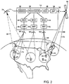
- Fig. 2 is a diagram of the two-way satellite communications system of Fig. 1 including a block diagram of two-way communication satellite; and
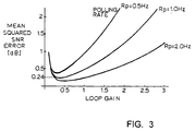
- Fig. 3 is a chart depicting optimization curves for loop gain versus mean squared SNR error for varying polling rates in an uplink power control system implementing the method of the present invention.
-
- Systems are currently being developed which allow satellite communications between many geographically dispersed uplink terminals with no central coordination using digital data packets. One example of such a system is illustrated in Figs. 1 and 2. A
communications system 10 is comprised of a network of one or more satellites 12-16 which services many earth-based terminals 18-30, and allows one terminal, such asterminal 22, to communicate directly with a second terminal, terminal 28, by transmitting a series of data packets specifically addressed to thesecond terminal 28. Each satellite 12-16 has the ability to receive uplink signals containing digital data packets from originating terminals and determine the target terminals to which the data packets are addressed. The satellites then route the data packets to a transmitter designated to transmit a downlink signal to the target terminal in a spot beam. - In the
communications system 10, an originatingterminal 22 creates a data packet containing header information identifying atarget terminal 28 to which the information is addressed, and a payload of digital data. The originatingterminal 22 modulates the data packet onto an uplink carrier frequency to create anuplink signal 32 which is transmitted to asatellite 14 within thesystem 10. Thesatellite 14 receives theuplink signal 32 at a receivingantenna 34, anddemodulator 36 demodulates theuplink signal 32 and converts theuplink signal 32 back into digital data. Aprocessor 38 identifies thetarget terminal 28 from the header information and routes the data packet for transmission to thetarget terminal 28. - The data packets must be reconvened into a transmittable downlink signal for transmission to the target terminal. The
processor 38 routes the data packet to the appropriate modulators 40-46 which modulate the data packets onto the downlink carrier frequency to create the downlink signals. The downlink signals are amplified by amplifiers 48-54 and retransmitted to the target terminals in spot beams by transmitters 56-62. In the present example, data packets addressed to target terminal 28 are routed tomodulator 44,amplifier 52 andtransmitter 60, thereby creating and transmittingdownlink signal 64 inspot beam 66. - Data packet routing may include hand-offs of the data packets to
other satellites system 10 that service the target terminals. For example, data transmitted from terminal 24 toterminal 30 would require an inter-satellite hand-off.Processor 38 ofsatellite 14 routes the data packets from terminal 24 tomodulator 46, amplifier 54 andtransmitter 62 for transmission tosatellite 16. The processor forsatellite 16 then routes the data packets to an on-board modulator, amplifier and transmitter for retransmission toterminal 30. - At the
target terminal 28, thedownlink signal 64 is demodulated and converted to digital data. Thetarget terminal 28 only processes the data packets addressed to that particular terminal.Terminal 28 discards data packets addressed to other terminals, such asterminal 26, which are serviced by thespot beam 66. - The system illustrated in Figs. 1 and 2 allows a first terminal to send messages made up of a series of digital data packets directly to a second terminal. In such a system, uplink power control and time synchronization can be accomplished with satellite-based measurements. In a first embodiment of the present invention, a terminal polls the satellite, requesting information of the uplink signal power and the transmission timing.
Terminal 22 transmits a data packet in theuplink signal 32 which contains a measurement request for thesatellite 14. The data packet has a "self-addressed" format which specifies terminal 22 as the target terminal for thedownlink signal 72. - The
uplink signal 32 is received by theantenna 34 and transferred todemodulator 36.Demodulator 36 demodulates theuplink signal 32 and converts the signal back into digital data.Demodulator 36 also measures the uplink signal power and the arrival time of theuplink signal 32.Processor 38 determines from the header information in the data packet that the packet is addressed toterminal 22 and that terminal 22 is requesting information of the measured power and arrival time of the uplink signal.Processor 38 responds to the measurement request in the data packet by adding the information to the data packet and routing the data packet tomodulator 40,amplifier 48 andtransmitter 56 for transmission to terminal 22 in thedownlink signal 72 inspot beam 74. The terminal 22 receives thedownlink signal 72 and determines that the data packet is addressed to the terminal 22. The terminal 22 adjusts the uplink signal power, the transmission timing, or both as dictated by the information in the data packet. - Parameters of a power control algorithm determine how the terminal will make the power and timing adjustments. However, the scope of the present invention is not limited to the use of a particular algorithm. Additionally, the location of execution of the power control algorithm is not critical to the method of the present invention. Execution could occur within the
satellite 14 at theprocessor 38. In this case, theprocessor 38 could format the data packet with the adjusted power level and transmission timing, or with some intermediate information which is used by the terminal 22 to arrive at the adjusted values. Conversely, theprocessor 38 could format the data packet with the raw data of the uplink power and arrival time, with execution of the algorithm occurring at the terminal 22. Other methods of implementing a power control and timing synchronization algorithm are contemplated by the present invention and will be obvious to those of ordinary skill in the art. - In another embodiment of the present invention, power control and time synchronization occur continuously as uplink signals are received by the satellite. In this embodiment, each uplink data packet contains address information identifying the originating terminal. The demodulator 36 measures the uplink power and arrival time of every uplink signal and the
processor 38 formats a new data packet with the address of the originating terminal and information of the measured uplink power and arrival time. Theprocessor 38 then routes the new data packet to the appropriate spot beam. This embodiment has the advantage that no conditional action is necessary to respond to a change in the link environment on the part of either the satellite or the terminal. - In another alternative embodiment, the satellite evaluates the power and timing measurements to determine how and when a terminal should adjust the uplink signal power and transmission timing. If adjustment is necessary, the satellite directly commands the terminal to adjust the power level, transmission timing, or both by formatting and transmitting a new data packet In this embodiment, the satellite only formats and transmits new data packets for a given terminal when an adjustment is necessary.
- The method of the present invention exploits the processing already required on-board the satellite to generate the required measurements which are reformatted and transmitted to the originating terminal. The satellite demodulator measures both the power level and the time of arrival of the uplink signal. The terminal filters the satellite-supplied data to adjust the uplink power and transmission timing. This assures a high quality link in two respects. First, it adapts transmit power to changing fades while keeping interference on other links to a minimum. Second, it adapts uplink signal transmission time to changing satellite range, allowing a tight guard time for high throughput efficiency.
- Computer simulations using measured Ka-band (27-31 GHz uplink, 17-21 GHz downlink) rain fade events have shown that acceptable power control and time synchronization can be achieved with a worst-case uplink polling rate of twice per second. Fig. 3 shows a loop gain optimization for a fade rate of 0.16 dB/second. The loop gain corresponds to the weight given to the most recent measurements when adjusting the uplink power and transmission timing. The mean squared signal-to-noise ratio (SNR) error represents the deviation of the uplink power measured at the satellite from the optimal power level. In these simulations, the SNR estimate was formed over a 32 chip burst preamble. Polling rates of 0.5, 1.0, and 2.0 Hz are shown. As can be seen, tracking accuracies of better than 0.5 dB can be achieved when the loop gain is optimized.
- Briefly summarized, the present invention relates to a method for uplink power control and time synchronization in a satellite communications system that is achieved using satellite-based measurements of the uplink signal power and signal arrival time. Uplink signals 32 transmitted from an originating
terminal 22 are received by acommunications satellite 14 which measures the received signal power and arrival time. Thesatellite 14 transmits adownlink signal 72 to the originatingterminal 22 containing information of the measured uplink signal power and arrival time. The originatingterminal 22 receives thedownlink signal 72 and transmits subsequent uplink signals 32 with an uplink signal power and transmission timing based on the information transmitted by the satellite. - While the present invention has been described with reference to specific examples, which are intended to be illustrative only and not to be limiting of the invention, it will be apparent to those of ordinary skill in the art that changes, additions, and/or deletions may be made to the disclosed embodiments without departing from the spirit and scope of the invention.
Claims (19)
- A method of adjusting an uplink signal power of a terminal (22) in a satellite communications system (10), the method comprising the steps of:transmitting an uplink signal (32) from an originating terminal (22) to a satellite (14), the uplink signal (32) being transmitted with a first transmitted uplink signal power;receiving the uplink signal (32) at the satellite (14), the uplink signal (32) received with a received uplink signal power;measuring the received uplink signal power at the satellite (14);transmitting information of the received uplink signal power from the satellite (14) to the originating terminal (22) in a downlink signal (72);receiving the downlink signal (72) at the originating terminal (22); andtransmitting subsequent uplink signals (32) with a second transmitted uplink signal power, the second transmitted uplink signal power being determined based on the transmitted information of the received uplink signal power.
- The method of claim 1, characterized in that the uplink signal (32) and the downlink signal (72) comprise data packets, the data packets containing information identifying the originating terminal (22).
- The method of claim 1 or 2, characterized in that the uplink signal (32) contains a measurement request causing the satellite (14) to transmit information of the received uplink power signal to the originating terminal (22).
- The method of any of the preceding claims, characterized in that the measuring step comprises the steps of:demodulating the received uplink signal (32) and measuring the received uplink signal power at the satellite (14);creating a downlink data packet for transmission to the originating terminal (22), the downlink data packet containing the identification information from the uplink data packet and the information of the received uplink signal power.
- The method of claim 4, characterized in that the creating step further comprises the step of adding identification information and information of the received uplink signal power to an existing data packet.
- The method of claim 4 or 5, characterized in that the step of creating the downlink data packet further comprises the step of calculating the second transmitted uplink signal power, wherein the information of the received uplink signal comprises the calculated second transmitted uplink signal power.
- The method of any of claims 4 through 6, characterized in that the step of transmitting information of the received uplink signal power further comprises the step of routing the downlink data packet to a transmitter (56) designated for transmitting downlink signals (72) to the originating terminal (22).
- The method of claim 7, characterized in that the designated transmitter (56) transmits a spot beam (74) on a geographic area encompassing the originating terminal (22).
- The method of any of the preceding claims, characterized in that the step of measuring the power level is performed continuously and automatically by the satellite (14).
- A method of adjusting a transmission timing of an uplink signal (32) of a terminal (22) in a satellite communications system (10) comprising the steps of:transmitting an uplink signal (32) from an originating terminal (22) to a satellite (14), the uplink signal (32) transmitted according to a first uplink signal transmission timing pattern;receiving the uplink signal (32) at the satellite (14), the uplink signal (32) received at an uplink signal arrival time;determining at the satellite (14) the uplink signal arrival time;transmitting timing information of the uplink signal arrival time from the satellite (14) to the originating terminal (22) in a downlink signal (72);receiving the downlink signal (72) at the originating terminal (22); andtransmitting subsequent uplink signals (32) according to a second uplink signal transmission timing pattern, the second uplink signal transmission timing pattern determined based on the transmitted timing information.
- The method of claim 10, characterized in that the uplink signal (32) and the downlink signal (72) comprise data packets, the data packets containing information identifying the originating terminal (22).
- The method of claim 10 or 11, characterized in that the uplink signal (32) contains a measurement request causing the satellite (14) to transmit information of the uplink signal arrival time to the originating terminal (22).
- The method of any of claims 10, 11 or 12, characterized in that the measuring step comprises the steps of:demodulating the received uplink signal (32) and measuring the uplink signal arrival time at the satellite (14);creating a downlink data packet for transmission to the originating terminal (22), the downlink data packet containing the identification information from the uplink data packet and the information of the uplink signal arrival time.
- The method of claim 13, characterized in that the creating step further comprises the step of adding identification information and information of the received uplink signal arrival time to an existing data packet.
- The method of claims 13 or 14, characterized in that the step of creating the downlink data packet further comprises the step of calculating the second uplink signal transmission timing pattern, wherein the information of the uplink signal arrival time comprises the calculated second uplink signal transmission timing pattern.
- The method of any of claims 13 through 15, characterized in that the step of transmitting information of the uplink signal arrival time further comprises the step of routing the downlink data packet to a transmitter (56) designated for transmitting downlink signals (72) to the originating terminal (22).
- The method of claim 16, characterized in that the designated transmitter (56) transmits a spot beam (74) on a geographic area encompassing the originating terminal (22).
- The method of any of claims 10 through 17, characterized in that the step of measuring the power level is performed continuously and automatically by the satellite (14).
- A method of adjusting an uplink signal power and a transmission timing of a terminal (22) in a satellite communications system (10), the method comprising the steps of:transmitting an uplink signal (32) from an originating terminal (22) to a satellite (14), the uplink signal (32) being transmitted with a first transmitted uplink signal power and transmitted according to a first uplink signal transmission timing pattern;receiving the uplink signal (32) at the satellite (14), the uplink signal (32) received with a received uplink signal power and received at an uplink signal arrival time;measuring the received uplink signal power at the satellite (14);determining at the satellite (14) the uplink signal arrival time;transmitting information of the received uplink signal power and the uplink signal arrival time from the satellite (14) to the originating terminal (32) in a downlink signal (72);receiving the downlink signal (72) at the originating terminal (22); andtransmitting subsequent uplink signals (32) with a second transmitted uplink signal power and according to a second uplink signal transmission timing pattern, the second transmitted uplink signal power being determined based on the transmitted information of the received uplink signal power and the second uplink signal transmission timing pattern determined based on the transmitted timing information.
Applications Claiming Priority (2)
| Application Number | Priority Date | Filing Date | Title |
|---|---|---|---|
| US106649 | 1998-06-29 | ||
| US09/106,649 US6335920B1 (en) | 1998-06-29 | 1998-06-29 | Satellite-based measurement for uplink power control and time synchronization |
Publications (3)
| Publication Number | Publication Date |
|---|---|
| EP0969607A2 true EP0969607A2 (en) | 2000-01-05 |
| EP0969607A3 EP0969607A3 (en) | 2002-09-18 |
| EP0969607B1 EP0969607B1 (en) | 2009-09-30 |
Family
ID=22312530
Family Applications (1)
| Application Number | Title | Priority Date | Filing Date |
|---|---|---|---|
| EP99110766A Expired - Lifetime EP0969607B1 (en) | 1998-06-29 | 1999-06-04 | Satellite-based measurement for uplink power control and time synchronization |
Country Status (3)
| Country | Link |
|---|---|
| US (1) | US6335920B1 (en) |
| EP (1) | EP0969607B1 (en) |
| DE (1) | DE69941469D1 (en) |
Cited By (2)
| Publication number | Priority date | Publication date | Assignee | Title |
|---|---|---|---|---|
| EP1168671A2 (en) * | 2000-06-26 | 2002-01-02 | Hughes Electronics Corporation | Uplink power control system for satellite communication system employing on-board satellite processing and fade estimation |
| US7043199B2 (en) | 2001-06-06 | 2006-05-09 | Hughes Network Systems Llc | Uplink power control system for satellite communication system employing on-board satellite processing and fade estimation |
Families Citing this family (19)
| Publication number | Priority date | Publication date | Assignee | Title |
|---|---|---|---|---|
| TW431087B (en) * | 1998-07-28 | 2001-04-21 | Sony Computer Entertainment Inc | Information transmission reception system and information transmission reception method, and information receiver used therein |
| US6724737B1 (en) * | 1999-06-17 | 2004-04-20 | Lockheed Martin Global Telecommunications, Inc | System for controlling communications between a terminal and satellite and method therefore |
| US6763006B1 (en) * | 1999-09-22 | 2004-07-13 | Sola Communications, Inc. | Method and apparatus for controlling uplink transmission power within a satellite communication system |
| US6633745B1 (en) | 2000-03-29 | 2003-10-14 | Societe Europeenne Des Satellites S.A. | Satellite cluster comprising a plurality of modular satellites |
| US6498937B1 (en) * | 2000-07-14 | 2002-12-24 | Trw Inc. | Asymmetric bandwidth wireless communication techniques |
| US6954581B2 (en) * | 2000-12-06 | 2005-10-11 | Microsoft Corporation | Methods and systems for managing multiple inputs and methods and systems for processing media content |
| US7047029B1 (en) | 2001-09-10 | 2006-05-16 | The Directv Group, Inc. | Adaptive transmission system |
| US9485010B1 (en) | 2001-09-10 | 2016-11-01 | The Directv Group, Inc. | Adaptive coding and modulation for spot beam satellite broadcast |
| US6882936B2 (en) * | 2003-03-03 | 2005-04-19 | Lockheed Martin Corporation | Integrated GPS/interference location system with anti-jam processor |
| US7653349B1 (en) | 2003-06-18 | 2010-01-26 | The Directv Group, Inc. | Adaptive return link for two-way satellite communication systems |
| US20050221853A1 (en) * | 2004-03-31 | 2005-10-06 | Silvester Kelan C | User authentication using a mobile phone SIM card |
| US7110717B2 (en) * | 2004-07-30 | 2006-09-19 | Viasat, Inc. | Leader-follower power control |
| US7599659B2 (en) * | 2005-03-10 | 2009-10-06 | The Boeing Company | Innovative combinational closed-loop and open-loop satellite user terminal power control system |
| US8159993B2 (en) * | 2006-09-26 | 2012-04-17 | Viasat, Inc. | Multi-user detection in satellite return link |
| US7974576B2 (en) * | 2007-02-09 | 2011-07-05 | Viasat, Inc. | Combined open and closed loop power control in a communications satellite |
| CN101675606A (en) * | 2007-03-08 | 2010-03-17 | 维尔塞特公司 | Satellite reference terminal systems and methods |
| US20090289839A1 (en) * | 2007-09-26 | 2009-11-26 | Viasat, Inc | Dynamic Sub-Channel Sizing |
| US8194582B2 (en) * | 2008-06-30 | 2012-06-05 | The Boeing Company | Method and apparatus for hosting commercially-derived packet routers on satellite payloads |
| JP6832794B2 (en) * | 2017-06-05 | 2021-02-24 | ルネサスエレクトロニクス株式会社 | Wireless communication system |
Citations (9)
| Publication number | Priority date | Publication date | Assignee | Title |
|---|---|---|---|---|
| US4004224A (en) * | 1972-01-17 | 1977-01-18 | Siemens Aktiengesellschaft | Method for fade correction of communication transmission over directional radio paths |
| US4577316A (en) * | 1984-02-13 | 1986-03-18 | Rca Corporation | Synchronization system for a regenerative subtransponder satellite communication system |
| US5265119A (en) * | 1989-11-07 | 1993-11-23 | Qualcomm Incorporated | Method and apparatus for controlling transmission power in a CDMA cellular mobile telephone system |
| US5333175A (en) * | 1993-01-28 | 1994-07-26 | Bell Communications Research, Inc. | Method and apparatus for dynamic power control in TDMA portable radio systems |
| EP0673130A1 (en) * | 1994-03-15 | 1995-09-20 | NEC Corporation | CDMA communication with a propagation delay between a base and a mobile station taken into account |
| EP0827293A2 (en) * | 1996-08-28 | 1998-03-04 | AT&T Corp. | Method of synchronizing satellite switched CDMA communication system |
| US5768684A (en) * | 1994-03-04 | 1998-06-16 | Motorola, Inc. | Method and apparatus for bi-directional power control in a digital communication system |
| WO1998026511A1 (en) * | 1996-12-12 | 1998-06-18 | Globalstar L.P. | Satellite controlled power control for personal communication user terminals |
| EP0909042A2 (en) * | 1997-10-10 | 1999-04-14 | TRW Inc. | Despreading of multiple independent CDMA sources in satellite communication system |
Family Cites Families (5)
| Publication number | Priority date | Publication date | Assignee | Title |
|---|---|---|---|---|
| US4941199A (en) * | 1989-04-06 | 1990-07-10 | Scientific Atlanta | Uplink power control mechanism for maintaining constant output power from satellite transponder |
| US5619525A (en) * | 1995-06-06 | 1997-04-08 | Globalstar L.P. | Closed loop power control for low earth orbit satellite communications system |
| US5864547A (en) * | 1996-08-21 | 1999-01-26 | Hughes Electronics Corporation | Method and system for controlling uplink power in a high data rate satellite communication system employing on-board demodulation and remodulation |
| CN1136741C (en) * | 1996-11-27 | 2004-01-28 | 株式会社日立制作所 | Transmission power control method and apparatus for mobile communication system |
| US5963865A (en) * | 1997-11-24 | 1999-10-05 | Telefonaktiebolaget Lm Ericsson | Traffic channel assignment in a cellular telephone system using an uplink interference driven frequency packing method |
-
1998
- 1998-06-29 US US09/106,649 patent/US6335920B1/en not_active Expired - Lifetime
-
1999
- 1999-06-04 EP EP99110766A patent/EP0969607B1/en not_active Expired - Lifetime
- 1999-06-04 DE DE69941469T patent/DE69941469D1/en not_active Expired - Lifetime
Patent Citations (9)
| Publication number | Priority date | Publication date | Assignee | Title |
|---|---|---|---|---|
| US4004224A (en) * | 1972-01-17 | 1977-01-18 | Siemens Aktiengesellschaft | Method for fade correction of communication transmission over directional radio paths |
| US4577316A (en) * | 1984-02-13 | 1986-03-18 | Rca Corporation | Synchronization system for a regenerative subtransponder satellite communication system |
| US5265119A (en) * | 1989-11-07 | 1993-11-23 | Qualcomm Incorporated | Method and apparatus for controlling transmission power in a CDMA cellular mobile telephone system |
| US5333175A (en) * | 1993-01-28 | 1994-07-26 | Bell Communications Research, Inc. | Method and apparatus for dynamic power control in TDMA portable radio systems |
| US5768684A (en) * | 1994-03-04 | 1998-06-16 | Motorola, Inc. | Method and apparatus for bi-directional power control in a digital communication system |
| EP0673130A1 (en) * | 1994-03-15 | 1995-09-20 | NEC Corporation | CDMA communication with a propagation delay between a base and a mobile station taken into account |
| EP0827293A2 (en) * | 1996-08-28 | 1998-03-04 | AT&T Corp. | Method of synchronizing satellite switched CDMA communication system |
| WO1998026511A1 (en) * | 1996-12-12 | 1998-06-18 | Globalstar L.P. | Satellite controlled power control for personal communication user terminals |
| EP0909042A2 (en) * | 1997-10-10 | 1999-04-14 | TRW Inc. | Despreading of multiple independent CDMA sources in satellite communication system |
Non-Patent Citations (1)
| Title |
|---|
| MARAL BOUSQUET: "Satellite Communications Systems" , SATELLITE COMMUNICATIONS SYSTEMS. SYSTEMS, TECHNIQUES AND TECHNOLOGY, WILEY SERIES IN COMMUNICATION AND DISTRIBUTED SYSTEMS, CHICHESTER, JOHN WILEY & SONS, GB, PAGE(S) 140-164 XP002196110 ISBN: 0-471-93032-6 * page 145 - page 150 * * |
Cited By (3)
| Publication number | Priority date | Publication date | Assignee | Title |
|---|---|---|---|---|
| EP1168671A2 (en) * | 2000-06-26 | 2002-01-02 | Hughes Electronics Corporation | Uplink power control system for satellite communication system employing on-board satellite processing and fade estimation |
| EP1168671A3 (en) * | 2000-06-26 | 2002-12-18 | Hughes Electronics Corporation | Uplink power control system for satellite communication system employing on-board satellite processing and fade estimation |
| US7043199B2 (en) | 2001-06-06 | 2006-05-09 | Hughes Network Systems Llc | Uplink power control system for satellite communication system employing on-board satellite processing and fade estimation |
Also Published As
| Publication number | Publication date |
|---|---|
| US6335920B1 (en) | 2002-01-01 |
| DE69941469D1 (en) | 2009-11-12 |
| EP0969607A3 (en) | 2002-09-18 |
| EP0969607B1 (en) | 2009-09-30 |
Similar Documents
| Publication | Publication Date | Title |
|---|---|---|
| EP0969607B1 (en) | Satellite-based measurement for uplink power control and time synchronization | |
| EP0969606B1 (en) | Dynamic power control with adaptive reference level | |
| US6724737B1 (en) | System for controlling communications between a terminal and satellite and method therefore | |
| US5511079A (en) | Apparatus and method for controlling forward error correction encoding in a very small aperture terminal | |
| EP0651531B1 (en) | Communication technique employing variable information transmission rate function of quality | |
| US6138012A (en) | Method and apparatus for reducing signal blocking in a satellite communication system | |
| KR100215947B1 (en) | Transmitting power control method in cdma | |
| US7532891B2 (en) | Method and apparatus for timing correction in communications systems | |
| US6212360B1 (en) | Methods and apparatus for controlling earth-station transmitted power in a VSAT network | |
| US4731866A (en) | Transmission power control system in a satellite communication | |
| AU654891B2 (en) | Transmitter power control system | |
| US7418263B2 (en) | Systems and methods for handover between space based and terrestrial radioterminal communications | |
| US8311491B2 (en) | Adaptive data rate control for narrowcast networks | |
| US7580673B2 (en) | Leader-follower power control | |
| US6430394B1 (en) | System for controlling communications between a terminal and satellite and method therefore | |
| US20100210262A1 (en) | Radioterminal system servers and methods | |
| US20230276323A1 (en) | Evolutionary game-based multi-user switching method in software-defined satellite network system | |
| EP0987840A2 (en) | A satellite communications system with call connection building | |
| JP2005502264A (en) | Satellite communication system and method using multiple simultaneous data rates | |
| KR20010051380A (en) | Closed loop power control for low earth orbit satellite communications system | |
| WO2006120669A2 (en) | Method and device for indirect communication within a wimax network | |
| JP4407900B2 (en) | Method of using event correlation to identify interfering mobile terminals | |
| EP1168661B1 (en) | Method and system for controlling uplink power in a satellite communication system using error levelling | |
| EP1168662A2 (en) | Method and apparatus for controlling a transmission power threshold of a satellite communication system | |
| US20020004401A1 (en) | Method for enhancing the reliability and efficiency of aeronautical data communications networks using synchronization data transmitted by VHF data link mode 4 aircraft stations |
Legal Events
| Date | Code | Title | Description |
|---|---|---|---|
| PUAI | Public reference made under article 153(3) epc to a published international application that has entered the european phase |
Free format text: ORIGINAL CODE: 0009012 |
|
| AK | Designated contracting states |
Kind code of ref document: A2 Designated state(s): AT BE CH CY DE DK ES FI FR GB GR IE IT LI LU MC NL PT SE |
|
| AX | Request for extension of the european patent |
Free format text: AL;LT;LV;MK;RO;SI |
|
| PUAL | Search report despatched |
Free format text: ORIGINAL CODE: 0009013 |
|
| AK | Designated contracting states |
Kind code of ref document: A3 Designated state(s): AT BE CH CY DE DK ES FI FR GB GR IE IT LI LU MC NL PT SE |
|
| AX | Request for extension of the european patent |
Free format text: AL;LT;LV;MK;RO;SI |
|
| 17P | Request for examination filed |
Effective date: 20030221 |
|
| 17Q | First examination report despatched |
Effective date: 20030331 |
|
| AKX | Designation fees paid |
Designated state(s): DE FR GB |
|
| APBN | Date of receipt of notice of appeal recorded |
Free format text: ORIGINAL CODE: EPIDOSNNOA2E |
|
| APBR | Date of receipt of statement of grounds of appeal recorded |
Free format text: ORIGINAL CODE: EPIDOSNNOA3E |
|
| APBV | Interlocutory revision of appeal recorded |
Free format text: ORIGINAL CODE: EPIDOSNIRAPE |
|
| 17Q | First examination report despatched |
Effective date: 20030331 |
|
| GRAP | Despatch of communication of intention to grant a patent |
Free format text: ORIGINAL CODE: EPIDOSNIGR1 |
|
| GRAS | Grant fee paid |
Free format text: ORIGINAL CODE: EPIDOSNIGR3 |
|
| GRAA | (expected) grant |
Free format text: ORIGINAL CODE: 0009210 |
|
| AK | Designated contracting states |
Kind code of ref document: B1 Designated state(s): DE FR GB |
|
| REG | Reference to a national code |
Ref country code: GB Ref legal event code: FG4D |
|
| REF | Corresponds to: |
Ref document number: 69941469 Country of ref document: DE Date of ref document: 20091112 Kind code of ref document: P |
|
| PLBE | No opposition filed within time limit |
Free format text: ORIGINAL CODE: 0009261 |
|
| STAA | Information on the status of an ep patent application or granted ep patent |
Free format text: STATUS: NO OPPOSITION FILED WITHIN TIME LIMIT |
|
| 26N | No opposition filed |
Effective date: 20100701 |
|
| REG | Reference to a national code |
Ref country code: FR Ref legal event code: PLFP Year of fee payment: 18 |
|
| PGFP | Annual fee paid to national office [announced via postgrant information from national office to epo] |
Ref country code: GB Payment date: 20160621 Year of fee payment: 18 Ref country code: DE Payment date: 20160621 Year of fee payment: 18 |
|
| PGFP | Annual fee paid to national office [announced via postgrant information from national office to epo] |
Ref country code: FR Payment date: 20160627 Year of fee payment: 18 |
|
| REG | Reference to a national code |
Ref country code: DE Ref legal event code: R119 Ref document number: 69941469 Country of ref document: DE |
|
| GBPC | Gb: european patent ceased through non-payment of renewal fee |
Effective date: 20170604 |
|
| REG | Reference to a national code |
Ref country code: FR Ref legal event code: ST Effective date: 20180228 |
|
| PG25 | Lapsed in a contracting state [announced via postgrant information from national office to epo] |
Ref country code: DE Free format text: LAPSE BECAUSE OF NON-PAYMENT OF DUE FEES Effective date: 20180103 Ref country code: GB Free format text: LAPSE BECAUSE OF NON-PAYMENT OF DUE FEES Effective date: 20170604 |
|
| PG25 | Lapsed in a contracting state [announced via postgrant information from national office to epo] |
Ref country code: FR Free format text: LAPSE BECAUSE OF NON-PAYMENT OF DUE FEES Effective date: 20170630 |