EP0970724A2 - Tumour treatment apparatus - Google Patents
Tumour treatment apparatus Download PDFInfo
- Publication number
- EP0970724A2 EP0970724A2 EP99119829A EP99119829A EP0970724A2 EP 0970724 A2 EP0970724 A2 EP 0970724A2 EP 99119829 A EP99119829 A EP 99119829A EP 99119829 A EP99119829 A EP 99119829A EP 0970724 A2 EP0970724 A2 EP 0970724A2
- Authority
- EP
- European Patent Office
- Prior art keywords
- fluid
- reservoir
- catheter
- chemotherapy
- balloon
- Prior art date
- Legal status (The legal status is an assumption and is not a legal conclusion. Google has not performed a legal analysis and makes no representation as to the accuracy of the status listed.)
- Withdrawn
Links
Images


Classifications
-
- A—HUMAN NECESSITIES
- A61—MEDICAL OR VETERINARY SCIENCE; HYGIENE
- A61M—DEVICES FOR INTRODUCING MEDIA INTO, OR ONTO, THE BODY; DEVICES FOR TRANSDUCING BODY MEDIA OR FOR TAKING MEDIA FROM THE BODY; DEVICES FOR PRODUCING OR ENDING SLEEP OR STUPOR
- A61M25/00—Catheters; Hollow probes
- A61M25/10—Balloon catheters
- A61M25/1011—Multiple balloon catheters
-
- A—HUMAN NECESSITIES
- A61—MEDICAL OR VETERINARY SCIENCE; HYGIENE
- A61M—DEVICES FOR INTRODUCING MEDIA INTO, OR ONTO, THE BODY; DEVICES FOR TRANSDUCING BODY MEDIA OR FOR TAKING MEDIA FROM THE BODY; DEVICES FOR PRODUCING OR ENDING SLEEP OR STUPOR
- A61M39/00—Tubes, tube connectors, tube couplings, valves, access sites or the like, specially adapted for medical use
- A61M39/02—Access sites
- A61M39/0208—Subcutaneous access sites for injecting or removing fluids
-
- A—HUMAN NECESSITIES
- A61—MEDICAL OR VETERINARY SCIENCE; HYGIENE
- A61N—ELECTROTHERAPY; MAGNETOTHERAPY; RADIATION THERAPY; ULTRASOUND THERAPY
- A61N1/00—Electrotherapy; Circuits therefor
- A61N1/40—Applying electric fields by inductive or capacitive coupling ; Applying radio-frequency signals
-
- A—HUMAN NECESSITIES
- A61—MEDICAL OR VETERINARY SCIENCE; HYGIENE
- A61N—ELECTROTHERAPY; MAGNETOTHERAPY; RADIATION THERAPY; ULTRASOUND THERAPY
- A61N1/00—Electrotherapy; Circuits therefor
- A61N1/40—Applying electric fields by inductive or capacitive coupling ; Applying radio-frequency signals
- A61N1/403—Applying electric fields by inductive or capacitive coupling ; Applying radio-frequency signals for thermotherapy, e.g. hyperthermia
-
- A—HUMAN NECESSITIES
- A61—MEDICAL OR VETERINARY SCIENCE; HYGIENE
- A61N—ELECTROTHERAPY; MAGNETOTHERAPY; RADIATION THERAPY; ULTRASOUND THERAPY
- A61N5/00—Radiation therapy
- A61N5/10—X-ray therapy; Gamma-ray therapy; Particle-irradiation therapy
- A61N5/1001—X-ray therapy; Gamma-ray therapy; Particle-irradiation therapy using radiation sources introduced into or applied onto the body; brachytherapy
- A61N5/1014—Intracavitary radiation therapy
- A61N5/1015—Treatment of resected cavities created by surgery, e.g. lumpectomy
-
- A—HUMAN NECESSITIES
- A61—MEDICAL OR VETERINARY SCIENCE; HYGIENE
- A61N—ELECTROTHERAPY; MAGNETOTHERAPY; RADIATION THERAPY; ULTRASOUND THERAPY
- A61N7/00—Ultrasound therapy
- A61N7/02—Localised ultrasound hyperthermia
-
- A—HUMAN NECESSITIES
- A61—MEDICAL OR VETERINARY SCIENCE; HYGIENE
- A61B—DIAGNOSIS; SURGERY; IDENTIFICATION
- A61B17/00—Surgical instruments, devices or methods, e.g. tourniquets
- A61B2017/00017—Electrical control of surgical instruments
- A61B2017/00022—Sensing or detecting at the treatment site
- A61B2017/00084—Temperature
-
- A—HUMAN NECESSITIES
- A61—MEDICAL OR VETERINARY SCIENCE; HYGIENE
- A61M—DEVICES FOR INTRODUCING MEDIA INTO, OR ONTO, THE BODY; DEVICES FOR TRANSDUCING BODY MEDIA OR FOR TAKING MEDIA FROM THE BODY; DEVICES FOR PRODUCING OR ENDING SLEEP OR STUPOR
- A61M25/00—Catheters; Hollow probes
- A61M25/10—Balloon catheters
- A61M25/1011—Multiple balloon catheters
- A61M2025/1013—Multiple balloon catheters with concentrically mounted balloons, e.g. being independently inflatable
-
- A—HUMAN NECESSITIES
- A61—MEDICAL OR VETERINARY SCIENCE; HYGIENE
- A61M—DEVICES FOR INTRODUCING MEDIA INTO, OR ONTO, THE BODY; DEVICES FOR TRANSDUCING BODY MEDIA OR FOR TAKING MEDIA FROM THE BODY; DEVICES FOR PRODUCING OR ENDING SLEEP OR STUPOR
- A61M39/00—Tubes, tube connectors, tube couplings, valves, access sites or the like, specially adapted for medical use
- A61M39/02—Access sites
- A61M39/0208—Subcutaneous access sites for injecting or removing fluids
- A61M2039/0211—Subcutaneous access sites for injecting or removing fluids with multiple chambers in a single site
-
- A—HUMAN NECESSITIES
- A61—MEDICAL OR VETERINARY SCIENCE; HYGIENE
- A61M—DEVICES FOR INTRODUCING MEDIA INTO, OR ONTO, THE BODY; DEVICES FOR TRANSDUCING BODY MEDIA OR FOR TAKING MEDIA FROM THE BODY; DEVICES FOR PRODUCING OR ENDING SLEEP OR STUPOR
- A61M2205/00—General characteristics of the apparatus
- A61M2205/32—General characteristics of the apparatus with radio-opaque indicia
-
- A—HUMAN NECESSITIES
- A61—MEDICAL OR VETERINARY SCIENCE; HYGIENE
- A61M—DEVICES FOR INTRODUCING MEDIA INTO, OR ONTO, THE BODY; DEVICES FOR TRANSDUCING BODY MEDIA OR FOR TAKING MEDIA FROM THE BODY; DEVICES FOR PRODUCING OR ENDING SLEEP OR STUPOR
- A61M2210/00—Anatomical parts of the body
- A61M2210/06—Head
- A61M2210/0687—Skull, cranium
-
- A—HUMAN NECESSITIES
- A61—MEDICAL OR VETERINARY SCIENCE; HYGIENE
- A61M—DEVICES FOR INTRODUCING MEDIA INTO, OR ONTO, THE BODY; DEVICES FOR TRANSDUCING BODY MEDIA OR FOR TAKING MEDIA FROM THE BODY; DEVICES FOR PRODUCING OR ENDING SLEEP OR STUPOR
- A61M2210/00—Anatomical parts of the body
- A61M2210/06—Head
- A61M2210/0693—Brain, cerebrum
-
- A—HUMAN NECESSITIES
- A61—MEDICAL OR VETERINARY SCIENCE; HYGIENE
- A61M—DEVICES FOR INTRODUCING MEDIA INTO, OR ONTO, THE BODY; DEVICES FOR TRANSDUCING BODY MEDIA OR FOR TAKING MEDIA FROM THE BODY; DEVICES FOR PRODUCING OR ENDING SLEEP OR STUPOR
- A61M27/00—Drainage appliance for wounds or the like, i.e. wound drains, implanted drains
- A61M27/002—Implant devices for drainage of body fluids from one part of the body to another
- A61M27/006—Cerebrospinal drainage; Accessories therefor, e.g. valves
-
- A—HUMAN NECESSITIES
- A61—MEDICAL OR VETERINARY SCIENCE; HYGIENE
- A61M—DEVICES FOR INTRODUCING MEDIA INTO, OR ONTO, THE BODY; DEVICES FOR TRANSDUCING BODY MEDIA OR FOR TAKING MEDIA FROM THE BODY; DEVICES FOR PRODUCING OR ENDING SLEEP OR STUPOR
- A61M39/00—Tubes, tube connectors, tube couplings, valves, access sites or the like, specially adapted for medical use
- A61M39/02—Access sites
- A61M39/0247—Semi-permanent or permanent transcutaneous or percutaneous access sites to the inside of the body
-
- A—HUMAN NECESSITIES
- A61—MEDICAL OR VETERINARY SCIENCE; HYGIENE
- A61M—DEVICES FOR INTRODUCING MEDIA INTO, OR ONTO, THE BODY; DEVICES FOR TRANSDUCING BODY MEDIA OR FOR TAKING MEDIA FROM THE BODY; DEVICES FOR PRODUCING OR ENDING SLEEP OR STUPOR
- A61M5/00—Devices for bringing media into the body in a subcutaneous, intra-vascular or intramuscular way; Accessories therefor, e.g. filling or cleaning devices, arm-rests
- A61M5/42—Devices for bringing media into the body in a subcutaneous, intra-vascular or intramuscular way; Accessories therefor, e.g. filling or cleaning devices, arm-rests having means for desensitising skin, for protruding skin to facilitate piercing, or for locating point where body is to be pierced
- A61M5/427—Locating point where body is to be pierced, e.g. vein location means using ultrasonic waves, injection site templates
-
- A—HUMAN NECESSITIES
- A61—MEDICAL OR VETERINARY SCIENCE; HYGIENE
- A61N—ELECTROTHERAPY; MAGNETOTHERAPY; RADIATION THERAPY; ULTRASOUND THERAPY
- A61N5/00—Radiation therapy
- A61N5/10—X-ray therapy; Gamma-ray therapy; Particle-irradiation therapy
- A61N5/1001—X-ray therapy; Gamma-ray therapy; Particle-irradiation therapy using radiation sources introduced into or applied onto the body; brachytherapy
- A61N2005/1019—Sources therefor
- A61N2005/1021—Radioactive fluid
-
- A—HUMAN NECESSITIES
- A61—MEDICAL OR VETERINARY SCIENCE; HYGIENE
- A61N—ELECTROTHERAPY; MAGNETOTHERAPY; RADIATION THERAPY; ULTRASOUND THERAPY
- A61N5/00—Radiation therapy
- A61N5/10—X-ray therapy; Gamma-ray therapy; Particle-irradiation therapy
- A61N5/1001—X-ray therapy; Gamma-ray therapy; Particle-irradiation therapy using radiation sources introduced into or applied onto the body; brachytherapy
- A61N5/1014—Intracavitary radiation therapy
Definitions
- the present invention relates to apparatus for the treatment of tumours in a living body, and more particularly, but not by way of limitation, to apparatus for treatment of brain tumours in a human.
- no currently available intraoperative therapeutic procedure utilizes the cavity formerly occupied by the bulk of the tumour for placement of an inflatable device for subsequent tumour therapy, whether combined (radiation and/or chemotherapy and/or hyperthermia together) or single modality (one of the above alone), or whether simultaneous or sequential in application.
- brachytherapy implantation of radioactive sources in the tumour and surrounding tissue
- Placement of catheters for afterlaoding must currently incorporate pre-operative placement of a stereotactic frame for localization, a procedure which is expensive, cumbersome, and time-consuming.
- frame placement a large heavy frame is attached to the skull of the awake patient utilizing transdermal metal screws and local anaesthetic, often not a smooth or desirable procedure.
- a CT scan and extensive calculations are required before the patient is transported to the operating room, with the frame on his or her head, for the actual catheter placements. This second transport is cumbersome.
- US-A-4816016 discloses an implantable apparatus for treatment of tissue surrounding a cavity left by surgical removal of a tumour from a living patient, comprising an inflatable balloon adapted to be placed in said cavity, and a catheter means for conducting treatment fluid to said inflated balloon.
- WO 90/04365 and WO 91/05528 disclose an implantable for treatment of tissue surrounding a cavity left by surgical removal of a tumour from a living patient, comprising an inflatable balloon adapted to be placed in said cavity, a catheter means for conducting treatment fluid to said inflatable balloon, and heating means operatively associated with said balloon for heating said treatment fluid while said treatment fluid is in said balloon.
- heating means comprises a chemotherapy apparatus for treatment of tissue surrounding a cavity left by a surgical excision, comprising:
- the apparatus of the present invention is non-invasive and does not require the use of wires extending out through an aperture in the patient's body.
- the apparatus of the present invention thus provides the possibility of simultaneous heat therapy and therapy by treatment flow.
- the treatment flow can be radioactive treatment fluid or a chemotherapy fluid, or in one embodiment a double-wall balloon is provided so that both a radioactive treatment fluid and a chemotherapy fluid can be simultaneously applied.
- Monitoring means may be provided for monitoring the temperature of the treatment fluid in the balloon.
- the invention provides a significant advantage in that it provides a means for simultaneous administration of radiation therapy and/or chemotherapy and/or heat therapy.
- Another advantage is that a treatment device is intraoperatively placed in the cavity formerly occupied by the bulk of the tumour thus providing a means for subsequent treatment of residual tumour without further surgical incisions.
- distensible balloon takes advantage of the inherent natural compliance of a fluid to conform to the outline of the cavity to be treated, thus allowing close approximation of the treatment device to the treated residual tumour.
- the present invention also takes advantage of the greater variety of desirable physical or superior cost properties inherent in readily available liquid isotopes. These liquid isotopes are cheaper and possess higher specific activities (millicuries per gram) when compared to their conventional, solid counterparts. This is a highly desirable characteristic which allows a higher concentration of radioactivity to be administered, thus resulting in higher tumour cell kill.
- Another advantage of the present invention is that it allows homogeneous mixing of disparate treatment agents for the uniform administration of hyperthermia and brachytherapy simultaneously to a human tumour surrounding a post-operative cavity.
- Fig 1 the coronal portion of the head of a human patient is shown and generally designated by the numeral 10.
- the patient's scalp 12 overlies the skull 14 within which is seen the brain 16.
- a tumour 18 is schematically illustrated within the brain tissue 16.
- the scalp 12 has been laid back as indicated at 20 and one or more burr holes have been cut to allow creation of a bone flap (not shown) which is removed to form an access opening 22 in the skull thus providing operative access to the brain 16 and the tumour 18.
- Fig. 2 the bulk of the tumour 18 has been operatively removed thus leaving a cavity 24 within the remaining brain tissue 16 which will include some residual tumour immediately surrounding the cavity 24.
- the implantable treatment apparatus 26 has been intra-operatively implanted prior to closure of the surgical incisions.
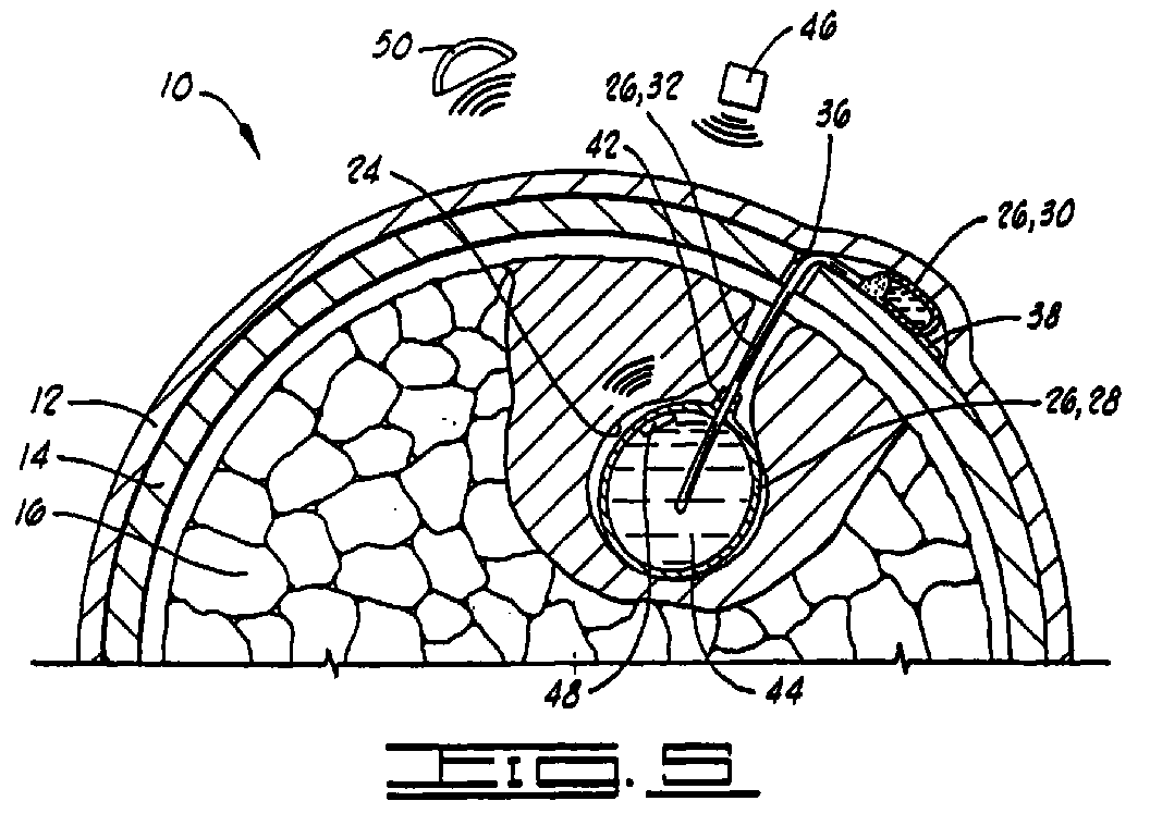
- the apparatus 26, as better seen in Fig. 5, includes an inflatable balloon 28 constructed for placement in the cavity 24, a subcutaneously implantable treatment fluid receptacle means 30, and a catheter means 32 connected between the receptacle means 30 and the balloon 28 for carrying treatment fluid from the receptacle means 30 to the inflatable balloon 28.
- the assembly of the implantable apparatus 26 is generally as follows starting with the subcutaneous receptacle 30 and moving distally.
- the various connections discussed in the following description are not shown in detail in the figures, but comprise conventional widely acceptable neurosurgical techniques and will be well understood by those skilled in the art.
- An outlet connector extends outwardly from the subcutaneous receptacle 30 and engages an end of the siliconized plastic surgical tubing comprising the catheter 32 in a manner like that shown in Fig 7 of U.S Patent No. 4,681,560 to Schulte et al.
- the end of the outlet connector from the subcutaneous receptacle 30 includes a flange portion which sealingly engages a suture sleeve to form a seal preventing medication from exiting the assembly other than through the connector leading to the catheter 32.
- a plastic right-angle device (not shown) which causes the catheter tube 32 to be conformed to a right angle can be placed around the tube at the time of installation at the proper linear dimension along the tube.
- the right-angle device may be located closer to or further from the subcutaneous receptacle 30.
- the apparatus 26 has been implanted with the balloon 28 located within cavity 24 but still in its uninflated state.
- the access opening 22 has been closed by replacement of the previously removed bone flap.
- the catheter means 32 is placed through a burr hole 36 which may have been formed when the bone flap was formed, or which may be specially formed in any desired location.
- the subcutaneous receptacle 30 has been placed on top of the skull 14 and the scalp 12 has been sutured back in place thereover.
- the receptacle 30 may include a suture tab such as 38 (see Fig. 5) allowing it to be sutured in place to the surrounding galea which is a tough overlying tissue which lies over the skull 14.
- a hypodermic needle 40 is illustrated as transdermally injecting a treatment fluid into the subcutaneous implanted receptacle 30.
- the injection receptacle 30 includes a rigid base and an overlying self-sealing dome which encloses and defines an injection chamber.
- the self-sealing dome is constructed of a silicone elastomer material, such materials providing an acceptable level of tissue reaction when subcutaneously implanted, which can be pierced by a 25 gauge or smaller needle without affecting ability of the dome to reseal after the needle is withdrawn.
- the fluid from needle 40 flows through the catheter 32 to inflate the balloon 28 so that it substantially fills the cavity 24 thus placing the treatment fluid in close proximity to the remaining tumour in the brain tissue 16 surrounding the cavity 24.
- the walls of balloon 28 can generally be described as being in direct apposition with the remaining residual tumour tissue surrounding cavity 24.
- various treatment modalities may be applied either individually or simultaneously.
- Fig. 5 illustrates the apparatus 26 in a view similar to that of Fig. 4 but enlarged and showing further detail.
- the subcutaneously implanted receptacle means 30 is constructed in a manner so that it can be easily and safely injected with the treatment fluid, and it is constructed of a material which will readily reseal upon withdrawal of the hypodermic needle. It may for example be constructed similarly to the subcutaneously implantable infusion reservoir shown and described in Schulte et al., U.S. Patents Nos. 4, 816, 016 and 4,681,560. It may also be an Onmaya CSF Reservoir such as is available from American Heyer-Schulte.
- the design of the subcutaneously implantable reservoir 30 should be small enough to minimize the volume or radioactive treatment fluid 44 in the subcutaneous area, but should be large enough to allow easy localization by palpation to facilitate loading with the hypodermic syringe 40.
- the subcutaneous receptacle 30 should be malleable and flexible to allow external palpation, but should be rigid enough that external compression cannot drive fluid from its interior into the catheter 32 and balloon 28. If compression should occur, the resilience of subcutaneous receptacle 30 should provide for re-expansion, thus reaccumulating any fluid driven distally as noted above.
- the catheter means 32 is constructed of conventional flexible plastic catheter materials.
- the inflatable balloon 28 which may also be referred to as a distensible reservoir 28 or distensible catheter 28, is preferably constructed of flexible siliconized plastic and is attached to the catheter means 32 location 42 by a flanged plastic connector and multiple interrupted surgical ties.
- the material from which the balloon wall is constructed need not be an elastic material. It is only required that the reservoir 28 be capable of somewhat collapsing in size so that it can be easily placed in cavity 24 as shown in Fig.3and that it then subsequently fill with fluid so as to substantially fill the cavity 24.
- the fluid inside balloon 28 is not necessarily pressurized, although it may be. The collapse of the balloon 28 following treatment will allow easy removal of the catheter 32 and balloon 28 through an exiting burr hole 36 without first removing the entire bone flap should removal of the device be required for any reason.
- the treatment fluid 44 is a radioactive treatment fluid.
- the radioactive treatment fluid can be injected into the balloon 28 and left there for a prescribed period of time. Then it may be removed by reinserting hypodermic needle 40 into receptacle 30 and pulling a vacuum with the plunger of hypodermic needle 40 to cause the treatment fluid to flow back out of balloon 28 through catheter 32 into receptacle 30 and into the cylinder of hypodermic needle 40, so as to end the radiation treatment.
- Preferred radioactive isotopes for use in this procedure include 90-Yttrium, 198-Gold, 32-Phosphorous, 125-Iodine and 131-Iodine.
- isotopes in liquid form allows considerable flexibility in administered dose rate in rad/hour and range (in millimetres) of the radioactive particles used in irradiating the residual tumour. Also with this apparatus a much more homogeneous dosage of radiation is applied to the surrounding tissue 16 than with the typical prior art devices described.
- the balloon 24 would be made of non-porous material.
- a balloon 28 constructed of porous material may be utilized in a manner similar to that described below with regard to the porous outer wall 28A of Fig.7, in order to allow the chemotherapy fluids to seep through the balloon 28 into actual contact with the surrounding brain tissue.
- the treatment device 26 may further include a check valve (not shown) disposed in catheter 32 similar to valve 82 of Fig.7 so that fluid can flow to balloon 28 but not back therefrom.
- the inflatable balloon 28 is preferably constructed so that it has an inflated volume as seen in Fig. 5 which is no greater than, and preferably slightly less than, the volume of the cavity 24 thus providing a means for avoiding any compression or distortion of the normal brain tissue 16 surrounding the cavity 24. It will be appreciated, of course, that distortion of the normal brain tissue can cause undesired complications.
- Fig.5 also illustrates a first form of heating means 46 operatively associated with the balloon means for28 for non-invasive heating of the treatment fluid 44 while the treatment fluid 44 is in the balloon 28.
- the heating means 46 illustrated in Fig.5 may either be an external ultrasonic transmission means 46 or an external radio frequency electromagnetic energy transmission means 46.
- the heating means 46 is an external ultrasonic transmission means, it focuses ultrasonic energy on the treatment fluid 44 in balloon 28. In the case of using ultrasonic energy to heat the balloon contents, the skull bone tissue 14 will not be replaced over the burr hole 22 thus providing a path for unimpeded transmission of the ultrasonic sound energy through the burr hole 22.
- the treatment fluid 44 will contain an iron oxide suspension in addition to the radioactive isotope in solution. This iron oxide suspension will be heated by the radio frequency electromagnetic energy.
- a monitoring means 48 is provided for monitoring a temperature of the treatment fluid 44 within the balloon means 28.
- the monitoring means 48 is a crystal oscillator 48 implanted within the balloon means 28.
- the oscillator 48 may also be mounted on the outside of catheter 32 within the balloon 28.
- the crystal oscillator 48 has a frequency of oscillation which varies proportionately to its temperature.
- the frequency of oscillation of the crystal oscillator means 48 can be determined non-invasively by an external antenna 40 which may be considered to be a part of the monitoring means.
- the crystal oscillator 48 is available under the trade name CorTemp from Human Technologies Inc of St. Moscow, Florida, such as described in "NASA Tech Briefs", June 1990, at page 106.
- the system shown in Fig.5 when using a non-porous balloon 28, provides a means for simultaneous application of both radioactive therapy and heat therapy to the remaining brain tissue 16 surrounding the cavity 24.
- the surgical procedure utilizing the apparatus of Fig.5 can be described as including steps of surgically removing at least a portion of the tumour 18 thereby creating the cavity 24 in the remaining brain tissue 16.
- the treatment device 26,28 is placed in the cavity 24 and the remaining tissue 16 including residual tumour surrounding the cavity 24 is treated by means of the treatment device 25,28.
- the treatment device 28 preferably is an inflatable balloon 28.
- the inflatable balloon is inflated with a treatment fluid 44 so that the inflatable device 28 occupies the cavity 24 thereby placing the treatment fluid 44 in close proximity to the remaining tissue 16 surrounding the cavity 24.
- the procedure can be performed non-invasively without making further surgical incisions on the patient.
- the apparatus and process of the present invention have been disclosed in the context of treatment of brain tumours, it will be appreciated that they can be used in connection with other types of tumours wherein treatment can be accomplished by placing the treatment device in a cavity left by removal of the tumour.
- the entire apparatus 26 can be left in place permanently allowing subsequent further treatment as desired.
- Fig.6 illustrates an alternative embodiment providing a different means for heating the treatment fluid 44 within the balloon 28.
- the system shown in Fig.6 utilizes an external microwave transmitter 52, and a subcutaneously implantable microwave receiver means 54.
- the microwave transmitter 52 preferably operate in the 200 MHz to 400 MHz range, and more preferably operates at about 300 MHz.
- the microwave receiver means 54 includes a metallic element 56 which actually receives the microwave energy and heats up.
- the microwave transmitter 52 may also be replaced by an ultrasound transmitter focussed on receiver means 54.
- Insulation 58 both overlies and underlies the metallic element 56 to prevent heating of the scalp 12 and underlying skull tissue 14.
- Suture tabs 60 may be used to attach the microwave receiver apparatus 54 to the skull 14.
- a conductor means 62 extends from the metallic element 56 into the interior of the balloon 28 for conducting heat from the metallic element 56 into the treatment fluid 44 in the balloon 28.
- the conductor means 62 has external insulation 64 which covers a metallic conductor 66 a portion of which is uncovered inside of the balloon 28.
- the conductor means 62 could be run through the hollow catheter 32.
- the system of Fig.6 may also use a temperature monitoring means 48,50 as shown in Fig.5.
- Fig.7 shows another alternative embodiment of the invention wherein the balloon is a double-wall balloon having a non-porous inner wall 28A, and a porous outer wall 28B.
- the first subcutaneously implantable receptacle 30 and catheter 32 previously described communicate with the non-porous inner wall 28A for providing the first treatment fluid 44 to the interior of the inner wall 28A.
- the first treatment fluid 44 is preferably a radioactive treatment fluid.
- the heating means 46 previously described is provided for non-invasive heating of the first treatment fluid 44.
- the alternative heating means of Fig.6 could also be utilized.
- a second subcutaneously implantable receptacle means 68 is provided for receiving a transdermal injection of a second treatment fluid 70, which preferably is a chemotherapy treatment fluid 70.
- the second receptacle 68 may beheld in place by suture tabs such as 69.
- a second catheter 72 communicates the second receptacle 68 with the space 74 defined between the inner and outer walls 28A and 28B within which the chemotherapy fluid 70 is received.
- the space 74 preferably has a layer of sponge-like material 76 lying therein between the inner and outer walls 28A and 28B for temporarily holding the chemotherapy fluid 70 therein.
- the porous outer wall 28B includes numerous small openings 78 therein allowing the chemotherapy fluid 70 to seep out such as in droplets 80.
- the chemotherapy fluid seeps out the porous outer wall 28B into direct contact with the brain tissue 16 surrounding the cavity 24.
- the previously described crystal oscillator 48 may be placed within either the inner wall 28A or with in the outer wall 28B for monitoring of the temperature of the fluids therein as previously described.
- a check valve 82 may be disposed in the second catheter 72 for preventing flow of the chemotherapy fluid 70 back therethrough from space 74 back to receptacle 68.
- the one-way check valve 82 is available from Halkey-Roberts Corporation of St. Moscow, Florida, and may for example be constructed in accordance with the teachings of U.S. Patent No. 4,681,132 to Lardner.
- Fig.7 illustrates a treatment means including heating means 46 and the first and second subcutaneous receptacles 30 and 68 operably associated with the balloon means 28A,28B for simultaneously non-invasively applying at least two, and if preferred all three, treatment modalities from the group consisting of radiation, heat and chemotherapy to remaining brain tissue 16 surrounding cavity 24.
- Fig.8 illustrates a balloon 28 like that of Fig.5 and also illustrates the fact that certain aspects of the present invention can be achieved without the use of the subcutaneously implanted receptacle 30, but instead by having a transdermal catheter 84 extend through the skull 14 and scalp 12 by means of a hollow bolt 86 implanted in the skull 14 which has the transdermal catheter 84 sealingly and securely disposed therethrough.
- the hollow bolt 86 may if desired be made of non-metallic materials.
- Figs 9 and 10 illustrate another embodiment of the invention.
- a modified subcutaneously implantable receptacle 88 is illustrated. It is connected to balloon 28 by catheter 32.
- the subcutaneously implantable reservoir 30 shown in Figs. 1-7 is designed such that the overlying scalp 12 is somewhat deformed to accommodate the size of the subcutaneous receptacle 30.
- the subcutaneous receptacle 30 of Figs. 1-7 is typically located by palpation of the scalp 40 so as to locate the subcutaneous reservoir 30 by feel.
- a palpable receptacle such as receptacle 30 implies pressure upon the overlying scalp 12 which may compromise blood supplied to the scalp 12 in that area, hence potentially causing skin necrosis or breakdown, a definite disadvantage.
- the modified receptacle 88 is circular in shape and includes an annular metallic ring 90 which is impenetrable by X-rays.
- the receptacle 88 and metallic ring 90 are placed with a counterbore 92 which is formed within the skull 14 with commonly utilized air-driven drills such as that manufactured by the Midas Rex Company.
- the receptacle 88 may be held in place by suture tabs 94. It may also be held in place by conventional threaded screws (not shown) screwed into the skull 14.
- the modified receptacle 88 may be installed in such a manner so as not to deform the overlying scalp 12 or create undue pressure upon the scalp 12. It does, however, present a need for an easy means of accurately locating the subcutaneous receptacle 88 so that treatment fluids may be injected therein with hypodermic needle similar to the process illustrated in Fig.4. This localisation is accomplished as shown in Fig. 10.
- a metallic grid 94 is laid in place over the patient's scalp 12 and may be held fixedly in place thereon by means such as tape 96.
- a plain en face radiograph, i.e. X-ray, of scalp, reservoir, grid and skull is taken.
- the relationship between the external metallic grid 94 and the subcutaneous metallic ring 90 may be easily seen, allowing selection of the correct grid square externally through which the hypodermic needle 40 can be successfully passed to hit the centre of the subcutaneous receptacle 88.
Abstract
Description
- The present invention relates to apparatus for the treatment of tumours in a living body, and more particularly, but not by way of limitation, to apparatus for treatment of brain tumours in a human.
- Conventional techniques of post-operative treatment of residual tumour following only gross removal of tumour include sequential, but not simultaneous administration of radiation, chemotherapy, and/or heat. Simultaneous administration of these modalities to the residual tumour is advantageous but impossible utilizing currently available techniques.
- Further, no currently available intraoperative therapeutic procedure utilizes the cavity formerly occupied by the bulk of the tumour for placement of an inflatable device for subsequent tumour therapy, whether combined (radiation and/or chemotherapy and/or hyperthermia together) or single modality (one of the above alone), or whether simultaneous or sequential in application.
- The current practice of brachytherapy (implantation of radioactive sources in the tumour and surrounding tissue) requires simultaneous placement of numerous separate catheters. Placement of catheters for afterlaoding must currently incorporate pre-operative placement of a stereotactic frame for localization, a procedure which is expensive, cumbersome, and time-consuming. In frame placement, a large heavy frame is attached to the skull of the awake patient utilizing transdermal metal screws and local anaesthetic, often not a smooth or desirable procedure. Once the frame is placed, a CT scan and extensive calculations are required before the patient is transported to the operating room, with the frame on his or her head, for the actual catheter placements. This second transport is cumbersome.
- Once in the operating room, numerous separate holes (usually up to 24) are manually drilled in the patient's scalp and skull. Then existing catheters are placed to the appropriate depth and sewn in place. These catheters are subsequently afterloaded with solid isotopic pellets for a prescribed time. The pellets are removed and, if hyperthermia is desired, separate metal antennae are loaded into the existing catheters for subsequent heating and thermometry. Although reasonably proximal in time, these sequential loadings reduce the efficacy of combined treatment, which should be simultaneous for highest tumour kill. During treatment, the catheters are externally exposed with attendant risk of infection.
- Following delivery of the prescribed radiation and heat, the catheters are removed. Any subsequent treatment, as for example following tumour recurrence, would require repeating the entire sequence described above.
- US-A-4816016 discloses an implantable apparatus for treatment of tissue surrounding a cavity left by surgical removal of a tumour from a living patient, comprising an inflatable balloon adapted to be placed in said cavity, and a catheter means for conducting treatment fluid to said inflated balloon.
-
WO 90/04365 and WO 91/05528 disclose an implantable for treatment of tissue surrounding a cavity left by surgical removal of a tumour from a living patient, comprising an inflatable balloon adapted to be placed in said cavity, a catheter means for conducting treatment fluid to said inflatable balloon, and heating means operatively associated with said balloon for heating said treatment fluid while said treatment fluid is in said balloon. - Starting from the disclosure of these two documents, the present invention said heating means comprises a chemotherapy apparatus for treatment of tissue surrounding a cavity left by a surgical excision, comprising:
- a distensible inner reservoir and outer reservoir, the outer reservoir comprising a porous wall and the inner reservoir comprising a non-porous wall, the inner and outer reservoirs arranged so that a space is defined between them;
- a first catheter connected to the space between the inner and outer reservoirs for delivery of a chemotherapy fluid into the space; and
- a second catheter connected to the inner reservoir for delivery of a second fluid into the inner reservoir.
-
- The apparatus of the present invention is non-invasive and does not require the use of wires extending out through an aperture in the patient's body.
- The apparatus of the present invention thus provides the possibility of simultaneous heat therapy and therapy by treatment flow.
- The treatment flow can be radioactive treatment fluid or a chemotherapy fluid, or in one embodiment a double-wall balloon is provided so that both a radioactive treatment fluid and a chemotherapy fluid can be simultaneously applied.
- Monitoring means may be provided for monitoring the temperature of the treatment fluid in the balloon.
- The invention provides a significant advantage in that it provides a means for simultaneous administration of radiation therapy and/or chemotherapy and/or heat therapy.
- Another advantage is that a treatment device is intraoperatively placed in the cavity formerly occupied by the bulk of the tumour thus providing a means for subsequent treatment of residual tumour without further surgical incisions.
- Another advantage is that the distensible balloon takes advantage of the inherent natural compliance of a fluid to conform to the outline of the cavity to be treated, thus allowing close approximation of the treatment device to the treated residual tumour.
- The present invention also takes advantage of the greater variety of desirable physical or superior cost properties inherent in readily available liquid isotopes. These liquid isotopes are cheaper and possess higher specific activities (millicuries per gram) when compared to their conventional, solid counterparts. This is a highly desirable characteristic which allows a higher concentration of radioactivity to be administered, thus resulting in higher tumour cell kill.
- Another advantage of the present invention is that it allows homogeneous mixing of disparate treatment agents for the uniform administration of hyperthermia and brachytherapy simultaneously to a human tumour surrounding a post-operative cavity.
- Numerous other objects, features and advantages of the present invention will be readily apparent to those skilled in the art upon a reading of the following disclosure when taken in conjunction with the accompanying drawings.
- Figs 1-4 comprise a sequential series of schematic elevation sectioned drawings through the coronal portion of the head of a human being. In Fig. 1 the scalp has been laid back and one or more burr holes are placed in the skull allowing creation of a circular bone flap which when temporarily removed allows gross resection of the tumour. In Fig. 2 the major portion of a brain tumour has been operatively removed. In Fig. 3 intra-operative placement of the implantable apparatus of the present invention has been accomplished and the incision has been closed. In Fig. 4 a hypodermic needle is used to transdermally place a treatment fluid in the apparatus to inflate the distensible catheter in place within the cavity formed by removal of the tumour.
- Fig. 5 is an enlarged view similar to Fig. 4 illustrating further details of the apparatus including means for heating and means for monitoring the temperature of the fluid in the balloon.
- Fig. 6 is a view similar to Fig. 5 illustrating alternative means for heating.
- Fig. 7 is a view similar to Fig. 5 illustrating an alternative embodiment of the invention having a double-wall balloon to allow chemotherapy treatments.
- Fig. 8 is a view similar to Fig. 5 of another alternative embodiment which is not completely implantable, and which has the catheter extending through a bolt means placed in the skull.
- Fig. 9 is a view similar to Fig. 5 of another alternative embodiment having a treatment fluid receptacle countersunk within the skull so as to avoid deformation of the overlying scalp. The implantable receptacle includes a metallic ring which is visible to X-rays.
- Fig. 10 schematically illustrates the placement of a metallic wire grid over the patients scalp, with the metallic ring of the device of Fig. 9 being shown in dashed lines as it would be seen in a subsequent en face X-ray of the patient's scalp for purposes of locating the receptacle.
-
- In Fig 1 the coronal portion of the head of a human patient is shown and generally designated by the
numeral 10. The patient'sscalp 12 overlies theskull 14 within which is seen thebrain 16. Atumour 18 is schematically illustrated within thebrain tissue 16. Thescalp 12 has been laid back as indicated at 20 and one or more burr holes have been cut to allow creation of a bone flap (not shown) which is removed to form an access opening 22 in the skull thus providing operative access to thebrain 16 and thetumour 18. - In Fig. 2, the bulk of the
tumour 18 has been operatively removed thus leaving acavity 24 within theremaining brain tissue 16 which will include some residual tumour immediately surrounding thecavity 24. - In Fig.3, the implantable treatment apparatus 26 has been intra-operatively implanted prior to closure of the surgical incisions. The apparatus 26, as better seen in Fig. 5, includes an
inflatable balloon 28 constructed for placement in thecavity 24, a subcutaneously implantable treatment fluid receptacle means 30, and a catheter means 32 connected between the receptacle means 30 and theballoon 28 for carrying treatment fluid from the receptacle means 30 to theinflatable balloon 28. - The assembly of the implantable apparatus 26 is generally as follows starting with the subcutaneous receptacle 30 and moving distally. The various connections discussed in the following description are not shown in detail in the figures, but comprise conventional widely acceptable neurosurgical techniques and will be well understood by those skilled in the art. An outlet connector extends outwardly from the subcutaneous receptacle 30 and engages an end of the siliconized plastic surgical tubing comprising the
catheter 32 in a manner like that shown in Fig 7 of U.S Patent No. 4,681,560 to Schulte et al. The end of the outlet connector from the subcutaneous receptacle 30 includes a flange portion which sealingly engages a suture sleeve to form a seal preventing medication from exiting the assembly other than through the connector leading to thecatheter 32. - In order for the
catheter 32 to make the right-angle turn downward throughburr hole 36 as illustrated in Fig. 5, a plastic right-angle device (not shown) which causes thecatheter tube 32 to be conformed to a right angle can be placed around the tube at the time of installation at the proper linear dimension along the tube. Thus, depending upon the necessary distance between the subcutaneous receptacle 30 and theburr hole 36, the right-angle device may be located closer to or further from the subcutaneous receptacle 30. These assembly techniques just described confer considerable flexibility in the placement and installation of the various components of the treatment device 26. - In Fig. 3, the apparatus 26 has been implanted with the
balloon 28 located withincavity 24 but still in its uninflated state. The access opening 22 has been closed by replacement of the previously removed bone flap. The catheter means 32 is placed through aburr hole 36 which may have been formed when the bone flap was formed, or which may be specially formed in any desired location. The subcutaneous receptacle 30 has been placed on top of theskull 14 and thescalp 12 has been sutured back in place thereover. The receptacle 30 may include a suture tab such as 38 (see Fig. 5) allowing it to be sutured in place to the surrounding galea which is a tough overlying tissue which lies over theskull 14. - In Fig. 4 a
hypodermic needle 40 is illustrated as transdermally injecting a treatment fluid into the subcutaneous implanted receptacle 30. The injection receptacle 30 includes a rigid base and an overlying self-sealing dome which encloses and defines an injection chamber. The self-sealing dome is constructed of a silicone elastomer material, such materials providing an acceptable level of tissue reaction when subcutaneously implanted, which can be pierced by a 25 gauge or smaller needle without affecting ability of the dome to reseal after the needle is withdrawn. The fluid fromneedle 40 flows through thecatheter 32 to inflate theballoon 28 so that it substantially fills thecavity 24 thus placing the treatment fluid in close proximity to the remaining tumour in thebrain tissue 16 surrounding thecavity 24. The walls ofballoon 28 can generally be described as being in direct apposition with the remaining residual tumourtissue surrounding cavity 24. As further described below, various treatment modalities may be applied either individually or simultaneously. - Fig. 5 illustrates the apparatus 26 in a view similar to that of Fig. 4 but enlarged and showing further detail.
- The subcutaneously implanted receptacle means 30 is constructed in a manner so that it can be easily and safely injected with the treatment fluid, and it is constructed of a material which will readily reseal upon withdrawal of the hypodermic needle. It may for example be constructed similarly to the subcutaneously implantable infusion reservoir shown and described in Schulte et al., U.S. Patents Nos. 4, 816, 016 and 4,681,560. It may also be an Onmaya CSF Reservoir such as is available from American Heyer-Schulte. The design of the subcutaneously implantable reservoir 30 should be small enough to minimize the volume or
radioactive treatment fluid 44 in the subcutaneous area, but should be large enough to allow easy localization by palpation to facilitate loading with thehypodermic syringe 40. The subcutaneous receptacle 30 should be malleable and flexible to allow external palpation, but should be rigid enough that external compression cannot drive fluid from its interior into thecatheter 32 andballoon 28. If compression should occur, the resilience of subcutaneous receptacle 30 should provide for re-expansion, thus reaccumulating any fluid driven distally as noted above. - The catheter means 32 is constructed of conventional flexible plastic catheter materials.
- The
inflatable balloon 28, which may also be referred to as adistensible reservoir 28 ordistensible catheter 28, is preferably constructed of flexible siliconized plastic and is attached to the catheter means 32location 42 by a flanged plastic connector and multiple interrupted surgical ties. - Although the term "balloon" is used to described the
distensible reservoir 28, it will be appreciated that the material from which the balloon wall is constructed need not be an elastic material. It is only required that thereservoir 28 be capable of somewhat collapsing in size so that it can be easily placed incavity 24 as shown in Fig.3and that it then subsequently fill with fluid so as to substantially fill thecavity 24. The fluid insideballoon 28 is not necessarily pressurized, although it may be. The collapse of theballoon 28 following treatment will allow easy removal of thecatheter 32 andballoon 28 through an exitingburr hole 36 without first removing the entire bone flap should removal of the device be required for any reason. - In one preferred embodiment the
treatment fluid 44 is a radioactive treatment fluid. The radioactive treatment fluid can be injected into theballoon 28 and left there for a prescribed period of time. Then it may be removed by reinsertinghypodermic needle 40 into receptacle 30 and pulling a vacuum with the plunger ofhypodermic needle 40 to cause the treatment fluid to flow back out ofballoon 28 throughcatheter 32 into receptacle 30 and into the cylinder ofhypodermic needle 40, so as to end the radiation treatment. Preferred radioactive isotopes for use in this procedure include 90-Yttrium, 198-Gold, 32-Phosphorous, 125-Iodine and 131-Iodine. The use of isotopes in liquid form allows considerable flexibility in administered dose rate in rad/hour and range (in millimetres) of the radioactive particles used in irradiating the residual tumour. Also with this apparatus a much more homogeneous dosage of radiation is applied to the surroundingtissue 16 than with the typical prior art devices described. - It is noted that since the apparatus of 26 can be loaded with radioactive solution after the completion of surgery there is much less danger of radiation exposure to operating room personnel than with the prior art techniques described above.
- Of course for treatment with
radioactive fluid 44, theballoon 24 would be made of non-porous material. For other treatment modalities, namely chemotherapy, aballoon 28 constructed of porous material may be utilized in a manner similar to that described below with regard to the porousouter wall 28A of Fig.7, in order to allow the chemotherapy fluids to seep through theballoon 28 into actual contact with the surrounding brain tissue. When aporous balloon wall 28 is used for chemotherapy, so that there is no need to ever withdraw the treatment fluid from theballoon 28, the treatment device 26 may further include a check valve (not shown) disposed incatheter 32 similar tovalve 82 of Fig.7 so that fluid can flow to balloon 28 but not back therefrom. - It is noted that the
inflatable balloon 28 is preferably constructed so that it has an inflated volume as seen in Fig. 5 which is no greater than, and preferably slightly less than, the volume of thecavity 24 thus providing a means for avoiding any compression or distortion of thenormal brain tissue 16 surrounding thecavity 24. It will be appreciated, of course, that distortion of the normal brain tissue can cause undesired complications. - Fig.5 also illustrates a first form of heating means 46 operatively associated with the balloon means for28 for non-invasive heating of the
treatment fluid 44 while thetreatment fluid 44 is in theballoon 28. The heating means 46 illustrated in Fig.5 may either be an external ultrasonic transmission means 46 or an external radio frequency electromagnetic energy transmission means 46. - If the heating means 46 is an external ultrasonic transmission means, it focuses ultrasonic energy on the
treatment fluid 44 inballoon 28. In the case of using ultrasonic energy to heat the balloon contents, theskull bone tissue 14 will not be replaced over theburr hole 22 thus providing a path for unimpeded transmission of the ultrasonic sound energy through theburr hole 22. - If the heating means 46 is an external radio frequency electromagnetic energy transmission means, the
treatment fluid 44 will contain an iron oxide suspension in addition to the radioactive isotope in solution. This iron oxide suspension will be heated by the radio frequency electromagnetic energy. - A monitoring means 48 is provided for monitoring a temperature of the
treatment fluid 44 within the balloon means 28. In a preferred embodiment, the monitoring means 48 is acrystal oscillator 48 implanted within the balloon means 28. Theoscillator 48 may also be mounted on the outside ofcatheter 32 within theballoon 28. Thecrystal oscillator 48 has a frequency of oscillation which varies proportionately to its temperature. The frequency of oscillation of the crystal oscillator means 48 can be determined non-invasively by anexternal antenna 40 which may be considered to be a part of the monitoring means. Thecrystal oscillator 48 is available under the trade name CorTemp from Human Technologies Inc of St. Petersburg, Florida, such as described in "NASA Tech Briefs", June 1990, at page 106. - The system shown in Fig.5 when using a
non-porous balloon 28, provides a means for simultaneous application of both radioactive therapy and heat therapy to the remainingbrain tissue 16 surrounding thecavity 24. - In its broadest aspects, the surgical procedure utilizing the apparatus of Fig.5 can be described as including steps of surgically removing at least a portion of the
tumour 18 thereby creating thecavity 24 in the remainingbrain tissue 16. Subsequently thetreatment device 26,28 is placed in thecavity 24 and the remainingtissue 16 including residual tumour surrounding thecavity 24 is treated by means of thetreatment device 25,28. Thetreatment device 28 preferably is aninflatable balloon 28. The inflatable balloon is inflated with atreatment fluid 44 so that theinflatable device 28 occupies thecavity 24 thereby placing thetreatment fluid 44 in close proximity to the remainingtissue 16 surrounding thecavity 24. By use of the subcutaneously implanted receptacle 30 and transdermal injections of treatment fluid as indicated in Fig.4, the procedure can be performed non-invasively without making further surgical incisions on the patient. Although the apparatus and process of the present invention have been disclosed in the context of treatment of brain tumours, it will be appreciated that they can be used in connection with other types of tumours wherein treatment can be accomplished by placing the treatment device in a cavity left by removal of the tumour. - The entire apparatus 26 can be left in place permanently allowing subsequent further treatment as desired.
- Fig.6 illustrates an alternative embodiment providing a different means for heating the
treatment fluid 44 within theballoon 28. - The system shown in Fig.6 utilizes an
external microwave transmitter 52, and a subcutaneously implantable microwave receiver means 54. Themicrowave transmitter 52 preferably operate in the 200 MHz to 400 MHz range, and more preferably operates at about 300 MHz. The microwave receiver means 54 includes ametallic element 56 which actually receives the microwave energy and heats up. Themicrowave transmitter 52 may also be replaced by an ultrasound transmitter focussed on receiver means 54.Insulation 58 both overlies and underlies themetallic element 56 to prevent heating of thescalp 12 andunderlying skull tissue 14.Suture tabs 60 may be used to attach themicrowave receiver apparatus 54 to theskull 14. - A conductor means 62 extends from the
metallic element 56 into the interior of theballoon 28 for conducting heat from themetallic element 56 into thetreatment fluid 44 in theballoon 28. The conductor means 62 has external insulation 64 which covers a metallic conductor 66 a portion of which is uncovered inside of theballoon 28. Alternatively the conductor means 62 could be run through thehollow catheter 32. - The system of Fig.6 may also use a temperature monitoring means 48,50 as shown in Fig.5.
- Fig.7 shows another alternative embodiment of the invention wherein the balloon is a double-wall balloon having a non-porous
inner wall 28A, and a porousouter wall 28B. The first subcutaneously implantable receptacle 30 andcatheter 32 previously described communicate with the non-porousinner wall 28A for providing thefirst treatment fluid 44 to the interior of theinner wall 28A. Thefirst treatment fluid 44 is preferably a radioactive treatment fluid. The heating means 46 previously described is provided for non-invasive heating of thefirst treatment fluid 44. The alternative heating means of Fig.6 could also be utilized. - A second subcutaneously implantable receptacle means 68 is provided for receiving a transdermal injection of a
second treatment fluid 70, which preferably is achemotherapy treatment fluid 70. Thesecond receptacle 68 may beheld in place by suture tabs such as 69. Asecond catheter 72 communicates thesecond receptacle 68 with the space 74 defined between the inner andouter walls chemotherapy fluid 70 is received. The space 74 preferably has a layer of sponge-like material 76 lying therein between the inner andouter walls chemotherapy fluid 70 therein. - The porous
outer wall 28B includes numeroussmall openings 78 therein allowing thechemotherapy fluid 70 to seep out such as in droplets 80. The chemotherapy fluid seeps out the porousouter wall 28B into direct contact with thebrain tissue 16 surrounding thecavity 24. - The previously described
crystal oscillator 48 may be placed within either theinner wall 28A or with in theouter wall 28B for monitoring of the temperature of the fluids therein as previously described. - A
check valve 82 may be disposed in thesecond catheter 72 for preventing flow of thechemotherapy fluid 70 back therethrough from space 74 back toreceptacle 68. The one-way check valve 82 is available from Halkey-Roberts Corporation of St. Petersburg, Florida, and may for example be constructed in accordance with the teachings of U.S. Patent No. 4,681,132 to Lardner. - It will be appreciated that fluid pressures both from the
first fluid 44 within theinner wall 28A and thesecond fluid 70 with the space 74 will act to urge thesecond fluid 70 out through thesmall openings 78 in the porousouter wall 28B. - Fig.7 illustrates a treatment means including heating means 46 and the first and second
subcutaneous receptacles 30 and 68 operably associated with the balloon means 28A,28B for simultaneously non-invasively applying at least two, and if preferred all three, treatment modalities from the group consisting of radiation, heat and chemotherapy to remainingbrain tissue 16 surroundingcavity 24. - Alternatively, instead of use of a double-
wall balloon outer wall 28 is a porous wall and wherein the interior thereof contains a sponge-like material. - Fig.8 illustrates a
balloon 28 like that of Fig.5 and also illustrates the fact that certain aspects of the present invention can be achieved without the use of the subcutaneously implanted receptacle 30, but instead by having atransdermal catheter 84 extend through theskull 14 andscalp 12 by means of ahollow bolt 86 implanted in theskull 14 which has thetransdermal catheter 84 sealingly and securely disposed therethrough. Thehollow bolt 86 may if desired be made of non-metallic materials. - Figs 9 and 10 illustrate another embodiment of the invention. In Fig.9 a modified subcutaneously
implantable receptacle 88 is illustrated. It is connected to balloon 28 bycatheter 32. - It will be appreciated that the subcutaneously implantable reservoir 30 shown in Figs. 1-7 is designed such that the overlying
scalp 12 is somewhat deformed to accommodate the size of the subcutaneous receptacle 30. The subcutaneous receptacle 30 of Figs. 1-7 is typically located by palpation of thescalp 40 so as to locate the subcutaneous reservoir 30 by feel. It will be appreciated that a palpable receptacle such as receptacle 30 implies pressure upon the overlyingscalp 12 which may compromise blood supplied to thescalp 12 in that area, hence potentially causing skin necrosis or breakdown, a definite disadvantage. - The modified
receptacle 88 is circular in shape and includes an annularmetallic ring 90 which is impenetrable by X-rays. Thereceptacle 88 andmetallic ring 90 are placed with acounterbore 92 which is formed within theskull 14 with commonly utilized air-driven drills such as that manufactured by the Midas Rex Company. Thereceptacle 88 may be held in place bysuture tabs 94. It may also be held in place by conventional threaded screws (not shown) screwed into theskull 14. - The modified
receptacle 88 may be installed in such a manner so as not to deform theoverlying scalp 12 or create undue pressure upon thescalp 12. It does, however, present a need for an easy means of accurately locating thesubcutaneous receptacle 88 so that treatment fluids may be injected therein with hypodermic needle similar to the process illustrated in Fig.4. This localisation is accomplished as shown in Fig. 10. - A
metallic grid 94 is laid in place over the patient'sscalp 12 and may be held fixedly in place thereon by means such astape 96. Next, a plain en face radiograph, i.e. X-ray, of scalp, reservoir, grid and skull is taken. By observing the X-ray film, the relationship between the externalmetallic grid 94 and the subcutaneousmetallic ring 90 may be easily seen, allowing selection of the correct grid square externally through which thehypodermic needle 40 can be successfully passed to hit the centre of thesubcutaneous receptacle 88.
Claims (10)
- A chemotherapy apparatus (10) for treatment of tissue surrounding a cavity (24) left by a surgical excision, comprising:a distensible inner reservoir (28A) and outer reservoir (28B), the outer reservoir comprising a porous wall and the inner reservoir comprising a non-porous wall, the inner and outer reservoirs arranged so that a space is defined between them;a first catheter (32) connected to the space between the inner and outer reservoirs for delivery of a chemotherapy fluid into the space; anda second catheter (72) connected to the inner reservoir for delivery of a second fluid into the inner reservoir.
- The apparatus according to claim 1, further comprising a first and second fluid receptacle (44,68) connected to the first and second catheter for receiving transdermal injections of the chemotherapy fluid and the second fluid, respectively.
- The apparatus according to claim 2, wherein the first and second receptacles are implanted subcutaneously.
- The apparatus according to claim 1, 2 or 3, wherein the space between inner and outer reservoirs comprises a sponge (76) for temporarily holding the chemotherapy fluid.
- The apparatus according any preceding claim, wherein the second fluid comprises a radioactive treatment fluid.
- The apparatus according to claim 5, wherein the radioactive treatment fluid comprises a radioisotope selected from the group consisting of "90-Yttrium, 198-Gold, 32-Phosphorus, 125-Iodine and 131-Iodine.
- The apparatus according to claim 5 or 6, wherein the outer reservoir includes means for spacing the inner reservoir from the tissue surrounding the cavity when the inner reservoir is filled with radioactive treatment fluid and the outer reservoir is filled with chemotherapy fluid.
- The apparatus of claims 1 to 7, further comprising an external energy transmitter for simultaneous application of heat energy to the tissue surrounding a cavity left by a surgical excision.
- The apparatus of claim 8, wherein the external energy transmitter is an ultrasonic transmitter, microwave transmitter or radio frequency transmitter.
- The apparatus of claim 8, further comprising a temperature monitor (48) in thermal communication with at least one of the reservoirs, the temperature monitor generating a signal responsive to the temperature of a fluid in the reservoir.
Applications Claiming Priority (3)
| Application Number | Priority Date | Filing Date | Title |
|---|---|---|---|
| US715923 | 1991-06-14 | ||
| US07/715,923 US5429582A (en) | 1991-06-14 | 1991-06-14 | Tumor treatment |
| EP92913085A EP0586567B1 (en) | 1991-06-14 | 1992-05-15 | Tumor treatment apparatus |
Related Parent Applications (1)
| Application Number | Title | Priority Date | Filing Date |
|---|---|---|---|
| EP92913085A Division EP0586567B1 (en) | 1991-06-14 | 1992-05-15 | Tumor treatment apparatus |
Publications (2)
| Publication Number | Publication Date |
|---|---|
| EP0970724A2 true EP0970724A2 (en) | 2000-01-12 |
| EP0970724A3 EP0970724A3 (en) | 2000-11-29 |
Family
ID=38051846
Family Applications (2)
| Application Number | Title | Priority Date | Filing Date |
|---|---|---|---|
| EP92913085A Expired - Lifetime EP0586567B1 (en) | 1991-06-14 | 1992-05-15 | Tumor treatment apparatus |
| EP99119829A Withdrawn EP0970724A3 (en) | 1991-06-14 | 1992-05-15 | Tumour treatment apparatus |
Family Applications Before (1)
| Application Number | Title | Priority Date | Filing Date |
|---|---|---|---|
| EP92913085A Expired - Lifetime EP0586567B1 (en) | 1991-06-14 | 1992-05-15 | Tumor treatment apparatus |
Country Status (6)
| Country | Link |
|---|---|
| US (4) | US5429582A (en) |
| EP (2) | EP0586567B1 (en) |
| JP (1) | JP3505622B2 (en) |
| CA (1) | CA2068281C (en) |
| DE (1) | DE69231294T2 (en) |
| WO (1) | WO1992022350A1 (en) |
Cited By (2)
| Publication number | Priority date | Publication date | Assignee | Title |
|---|---|---|---|---|
| WO2005049141A1 (en) * | 2003-11-14 | 2005-06-02 | Cytyc Corporation | Drug eluting brachytherapy methods and apparatus |
| FR3117334A1 (en) * | 2020-12-10 | 2022-06-17 | Commissariat à l'Energie Atomique et aux Energies Alternatives | Spot cooling device |
Families Citing this family (268)
| Publication number | Priority date | Publication date | Assignee | Title |
|---|---|---|---|---|
| US5429582A (en) * | 1991-06-14 | 1995-07-04 | Williams; Jeffery A. | Tumor treatment |
| US5931774A (en) | 1991-06-14 | 1999-08-03 | Proxima Therapeutics, Inc. | Inflatable devices for tumor treatment |
| US5443470A (en) * | 1992-05-01 | 1995-08-22 | Vesta Medical, Inc. | Method and apparatus for endometrial ablation |
| DK0633041T3 (en) | 1993-07-01 | 2000-04-03 | Schneider Europ Gmbh | Medical apparatus for the treatment of blood vessels by means of ionizing radiation |
| US6045495A (en) * | 1994-01-21 | 2000-04-04 | The Trustees Fo Columbia University In The City Of New York | Apparatus and method to treat a disease process in a luminal structure |
| US6217503B1 (en) * | 1994-01-21 | 2001-04-17 | The Trustees Of Columbia University In The City Of New York | Apparatus and method to treat a disease process in a luminal structure |
| US6129685A (en) * | 1994-02-09 | 2000-10-10 | The University Of Iowa Research Foundation | Stereotactic hypothalamic obesity probe |
| US5697975A (en) * | 1994-02-09 | 1997-12-16 | The University Of Iowa Research Foundation | Human cerebral cortex neural prosthetic for tinnitus |
| US7077822B1 (en) | 1994-02-09 | 2006-07-18 | The University Of Iowa Research Foundation | Stereotactic hypothalamic obesity probe |
| EP0686342B1 (en) | 1994-06-10 | 1998-09-09 | Schneider (Europe) GmbH | A medical appliance for the treatment of a portion of body vessel by ionising radiation |
| ATE196742T1 (en) | 1994-06-24 | 2000-10-15 | Schneider Europ Gmbh | MEDICINAL DEVICE FOR THE TREATMENT OF A PART OF A BODY VESSEL USING IONIZATION RADIATION |
| JP2927966B2 (en) * | 1994-07-12 | 1999-07-28 | フォトエレクトロン コーポレイション | X-ray apparatus for applying a predetermined flux to the inner layer surface of a body cavity |
| US5873852A (en) * | 1995-07-10 | 1999-02-23 | Interventional Technologies | Device for injecting fluid into a wall of a blood vessel |
| US6102904A (en) * | 1995-07-10 | 2000-08-15 | Interventional Technologies, Inc. | Device for injecting fluid into a wall of a blood vessel |
| EP0778051B1 (en) * | 1995-12-05 | 2003-04-09 | Schneider (Europe) GmbH | Filament for irradiating a living body and method for producing a filament for irradiating a living body |
| US6099454A (en) * | 1996-02-29 | 2000-08-08 | Scimed Life Systems, Inc. | Perfusion balloon and radioactive wire delivery system |
| US5855546A (en) | 1996-02-29 | 1999-01-05 | Sci-Med Life Systems | Perfusion balloon and radioactive wire delivery system |
| US6234951B1 (en) | 1996-02-29 | 2001-05-22 | Scimed Life Systems, Inc. | Intravascular radiation delivery system |
| US5882290A (en) * | 1996-02-29 | 1999-03-16 | Scimed Life Systems, Inc. | Intravascular radiation delivery system |
| AU712953B2 (en) * | 1996-03-11 | 1999-11-18 | Focal, Inc. | Polymeric delivery of radionuclides and radiopharmaceuticals |
| US5916143A (en) * | 1996-04-30 | 1999-06-29 | Apple; Marc G. | Brachytherapy catheter system |
| US7036516B1 (en) | 1996-10-30 | 2006-05-02 | Xantech Pharmaceuticals, Inc. | Treatment of pigmented tissues using optical energy |
| US20060095097A1 (en) * | 1996-10-30 | 2006-05-04 | Provectus Devicetech, Inc. | Treatment of pigmented tissue using optical energy |
| US6117064A (en) * | 1997-01-06 | 2000-09-12 | Apple; Marc G. | Catheter system |
| US6110097A (en) * | 1997-03-06 | 2000-08-29 | Scimed Life Systems, Inc. | Perfusion balloon catheter with radioactive source |
| US6676590B1 (en) | 1997-03-06 | 2004-01-13 | Scimed Life Systems, Inc. | Catheter system having tubular radiation source |
| US6059713A (en) * | 1997-03-06 | 2000-05-09 | Scimed Life Systems, Inc. | Catheter system having tubular radiation source with movable guide wire |
| US6059812A (en) * | 1997-03-21 | 2000-05-09 | Schneider (Usa) Inc. | Self-expanding medical device for centering radioactive treatment sources in body vessels |
| DE19720978A1 (en) * | 1997-05-20 | 1998-11-26 | Joern H Dr Risse | Insertion unit for locating radio-nuclides into the body of a human being or animal |
| US6019718A (en) | 1997-05-30 | 2000-02-01 | Scimed Life Systems, Inc. | Apparatus for intravascular radioactive treatment |
| US5913813A (en) | 1997-07-24 | 1999-06-22 | Proxima Therapeutics, Inc. | Double-wall balloon catheter for treatment of proliferative tissue |
| US6482142B1 (en) | 1997-07-24 | 2002-11-19 | Proxima Therapeutics, Inc. | Asymmetric radiation dosing apparatus and method |
| AT407009B (en) | 1997-09-01 | 2000-11-27 | Ali Dr Hassan | CATHETER DEVICE FOR RADIOACTIVE TREATMENT OF BODY CAVES |
| EP1011813A1 (en) | 1997-09-11 | 2000-06-28 | Cook Incorporated | Medical radiation treatment delivery apparatus |
| DE19742880A1 (en) * | 1997-09-23 | 1999-03-25 | Schering Ag | Treatment of proliferative or atherosclerotic diseases |
| EP0904798B1 (en) | 1997-09-26 | 2002-11-06 | Schneider ( Europe) GmbH | Carbon dioxide inflated radio-therapy balloon catheter |
| US6050943A (en) | 1997-10-14 | 2000-04-18 | Guided Therapy Systems, Inc. | Imaging, therapy, and temperature monitoring ultrasonic system |
| US6264596B1 (en) | 1997-11-03 | 2001-07-24 | Meadox Medicals, Inc. | In-situ radioactive medical device |
| WO1999029371A1 (en) * | 1997-12-05 | 1999-06-17 | Cook Incorporated | Medical radiation treatment device |
| EP1047362B1 (en) * | 1998-01-12 | 2004-10-27 | Ronald P. Lesser | Technique for using brain heat flow management to treat brain disorders |
| US6338709B1 (en) | 1998-02-19 | 2002-01-15 | Medtronic Percusurge, Inc. | Intravascular radiation therapy device and method of use |
| AU2773599A (en) | 1998-02-20 | 1999-09-06 | Cook Incorporated | Medical, radiotherapy source vial |
| US6036631A (en) * | 1998-03-09 | 2000-03-14 | Urologix, Inc. | Device and method for intracavitary cancer treatment |
| US6099499A (en) * | 1998-04-28 | 2000-08-08 | Medtronic, Inc. | Device for in vivo radiation delivery and method for delivery |
| US6093142A (en) * | 1998-04-30 | 2000-07-25 | Medtronic Inc. | Device for in vivo radiation delivery and method for delivery |
| US6315979B1 (en) | 1998-06-02 | 2001-11-13 | The Dow Chemical Company | Radioiodinated sulfonated phenols for brachytherapy |
| US6159143A (en) * | 1998-06-17 | 2000-12-12 | Scimed Life Systems, Inc. | Method and device for delivery of therapeutic agents in conjunction with isotope seed placement |
| US6413203B1 (en) | 1998-09-16 | 2002-07-02 | Scimed Life Systems, Inc. | Method and apparatus for positioning radioactive fluids within a body lumen |
| US6695830B2 (en) | 1999-01-15 | 2004-02-24 | Scimed Life Systems, Inc. | Method for delivering medication into an arterial wall for prevention of restenosis |
| US6210392B1 (en) | 1999-01-15 | 2001-04-03 | Interventional Technologies, Inc. | Method for treating a wall of a blood vessel |
| US6196963B1 (en) | 1999-03-02 | 2001-03-06 | Medtronic Ave, Inc. | Brachytherapy device assembly and method of use |
| US6464625B2 (en) * | 1999-06-23 | 2002-10-15 | Robert A. Ganz | Therapeutic method and apparatus for debilitating or killing microorganisms within the body |
| US6213976B1 (en) | 1999-07-22 | 2001-04-10 | Advanced Research And Technology Institute, Inc. | Brachytherapy guide catheter |
| US6238374B1 (en) | 1999-08-06 | 2001-05-29 | Proxima Therapeutics, Inc. | Hazardous fluid infuser |
| US6319189B1 (en) | 1999-09-13 | 2001-11-20 | Isotron, Inc. | Methods for treating solid tumors using neutron therapy |
| US6352501B1 (en) | 1999-09-23 | 2002-03-05 | Scimed Life Systems, Inc. | Adjustable radiation source |
| US6203485B1 (en) | 1999-10-07 | 2001-03-20 | Scimed Life Systems, Inc. | Low attenuation guide wire for intravascular radiation delivery |
| US6398709B1 (en) | 1999-10-19 | 2002-06-04 | Scimed Life Systems, Inc. | Elongated member for intravascular delivery of radiation |
| US7228171B2 (en) * | 1999-10-19 | 2007-06-05 | The Johns Hopkins University | Signal analysis, heat flow management, and stimulation techniques to treat medical disorders |
| US6882881B1 (en) * | 1999-10-19 | 2005-04-19 | The Johns Hopkins University | Techniques using heat flow management, stimulation, and signal analysis to treat medical disorders |
| US6416457B1 (en) | 2000-03-09 | 2002-07-09 | Scimed Life Systems, Inc. | System and method for intravascular ionizing tandem radiation therapy |
| US6302865B1 (en) | 2000-03-13 | 2001-10-16 | Scimed Life Systems, Inc. | Intravascular guidewire with perfusion lumen |
| EP1274377A2 (en) * | 2000-04-07 | 2003-01-15 | The General Hospital Corporation doing business as Massachusetts General Hospital | Methods and apparatus for thermally affecting tissue |
| US6497645B1 (en) | 2000-08-28 | 2002-12-24 | Isotron, Inc. | Remote afterloader |
| WO2002028330A1 (en) | 2000-10-05 | 2002-04-11 | Seacoast Technologies, Inc. | Neurosurgical device for thermal therapy |
| US20040034321A1 (en) * | 2000-10-05 | 2004-02-19 | Seacoast Technologies, Inc. | Conformal pad for neurosurgery and method thereof |
| WO2004026111A2 (en) | 2000-11-16 | 2004-04-01 | Microspherix Llc | Flexible and/or elastic brachytherapy seed or strand |
| US6514193B2 (en) * | 2000-11-16 | 2003-02-04 | Microspherix Llc | Method of administering a therapeutically active substance |
| US6866624B2 (en) * | 2000-12-08 | 2005-03-15 | Medtronic Ave,Inc. | Apparatus and method for treatment of malignant tumors |
| US7914453B2 (en) | 2000-12-28 | 2011-03-29 | Ardent Sound, Inc. | Visual imaging system for ultrasonic probe |
| US20020087206A1 (en) * | 2000-12-28 | 2002-07-04 | Henry Hirschberg | Implantable intracranial photo applicator for long term fractionated photodynamic and radiation therapy in the brain and method of using the same |
| US6527693B2 (en) * | 2001-01-30 | 2003-03-04 | Implant Sciences Corporation | Methods and implants for providing radiation to a patient |
| DE10105592A1 (en) | 2001-02-06 | 2002-08-08 | Achim Goepferich | Placeholder for drug release in the frontal sinus |
| EP1406693A4 (en) * | 2001-05-15 | 2007-06-06 | Univ Stellenbosch | Radiation application method and device |
| US6673006B2 (en) * | 2001-06-15 | 2004-01-06 | Proxima Therapeutics, Inc. | Tissue positioning apparatus and method for protecting tissue from radiotherapy |
| US6911017B2 (en) * | 2001-09-19 | 2005-06-28 | Advanced Cardiovascular Systems, Inc. | MRI visible catheter balloon |
| RU2219848C2 (en) * | 2001-12-03 | 2003-12-27 | Свадовский Александр Игоревич | Method for radical removal of parasagittal meningioma |
| US7048756B2 (en) * | 2002-01-18 | 2006-05-23 | Apasara Medical Corporation | System, method and apparatus for evaluating tissue temperature |
| US6850804B2 (en) * | 2002-01-18 | 2005-02-01 | Calfacior Corporation | System method and apparatus for localized heating of tissue |
| US6993394B2 (en) | 2002-01-18 | 2006-01-31 | Calfacion Corporation | System method and apparatus for localized heating of tissue |
| US7232429B2 (en) * | 2002-04-08 | 2007-06-19 | Boston Scientific Corporation | Medical devices |
| US20030204161A1 (en) * | 2002-04-25 | 2003-10-30 | Bozidar Ferek-Petric | Implantable electroporation therapy device and method for using same |
| DE60324448D1 (en) * | 2002-09-10 | 2008-12-11 | Cianna Medical Inc | brachytherapy |
| US8317816B2 (en) | 2002-09-30 | 2012-11-27 | Acclarent, Inc. | Balloon catheters and methods for treating paranasal sinuses |
| US6895282B2 (en) * | 2002-10-04 | 2005-05-17 | Boston Scientific Scimed, Inc. | Induction heating for the delivery of thermal therapy |
| US7041047B2 (en) | 2002-10-04 | 2006-05-09 | Boston Scientific Scimed, Inc. | Method and apparatus for the delivery of brachytherapy |
| US6923754B2 (en) * | 2002-11-06 | 2005-08-02 | Senorx, Inc. | Vacuum device and method for treating tissue adjacent a body cavity |
| US8328710B2 (en) * | 2002-11-06 | 2012-12-11 | Senorx, Inc. | Temporary catheter for biopsy site tissue fixation |
| US7004961B2 (en) * | 2003-01-09 | 2006-02-28 | Edward Wong | Medical device and method for temperature control and treatment of the brain and spinal cord |
| US7715896B2 (en) | 2003-03-21 | 2010-05-11 | Boston Scientific Scimed, Inc. | Systems and methods for internal tissue penetration |
| US20040218721A1 (en) * | 2003-04-30 | 2004-11-04 | Chornenky Victor I. | Miniature x-ray apparatus |
| US20040218724A1 (en) * | 2003-04-30 | 2004-11-04 | Chornenky Victor I. | Miniature x-ray emitter |
| US20050015049A1 (en) * | 2003-07-16 | 2005-01-20 | Rioux Robert F. | Temporary tissue spacer and pretreatment balloon |
| AU2003253284A1 (en) * | 2003-07-29 | 2005-02-15 | Humanitas Mirasole S.P.A. | A catheter for cerebral treatment with radioactive substances |
| JP2007511242A (en) * | 2003-09-03 | 2007-05-10 | ルビカー・メディカル・インコーポレーテッド | Temporary postoperative cavity processing apparatus and processing method |
| US7783006B2 (en) * | 2003-10-10 | 2010-08-24 | Xoft, Inc. | Radiation treatment using x-ray source |
| US20050080313A1 (en) * | 2003-10-10 | 2005-04-14 | Stewart Daren L. | Applicator for radiation treatment of a cavity |
| US7524274B2 (en) * | 2003-11-07 | 2009-04-28 | Cytyc Corporation | Tissue positioning systems and methods for use with radiation therapy |
| US7494457B2 (en) * | 2003-11-07 | 2009-02-24 | Cytyc Corporation | Brachytherapy apparatus and method for treating a target tissue through an external surface of the tissue |
| US7354391B2 (en) * | 2003-11-07 | 2008-04-08 | Cytyc Corporation | Implantable radiotherapy/brachytherapy radiation detecting apparatus and methods |
| US7371231B2 (en) * | 2004-02-02 | 2008-05-13 | Boston Scientific Scimed, Inc. | System and method for performing ablation using a balloon |
| US7582050B2 (en) * | 2004-03-31 | 2009-09-01 | The Regents Of The University Of California | Apparatus for hyperthermia and brachytherapy delivery |
| US20060063973A1 (en) | 2004-04-21 | 2006-03-23 | Acclarent, Inc. | Methods and apparatus for treating disorders of the ear, nose and throat |
| US8764729B2 (en) | 2004-04-21 | 2014-07-01 | Acclarent, Inc. | Frontal sinus spacer |
| US7419497B2 (en) | 2004-04-21 | 2008-09-02 | Acclarent, Inc. | Methods for treating ethmoid disease |
| US8146400B2 (en) | 2004-04-21 | 2012-04-03 | Acclarent, Inc. | Endoscopic methods and devices for transnasal procedures |
| US7462175B2 (en) | 2004-04-21 | 2008-12-09 | Acclarent, Inc. | Devices, systems and methods for treating disorders of the ear, nose and throat |
| US20060004323A1 (en) | 2004-04-21 | 2006-01-05 | Exploramed Nc1, Inc. | Apparatus and methods for dilating and modifying ostia of paranasal sinuses and other intranasal or paranasal structures |
| US8702626B1 (en) | 2004-04-21 | 2014-04-22 | Acclarent, Inc. | Guidewires for performing image guided procedures |
| US9089258B2 (en) | 2004-04-21 | 2015-07-28 | Acclarent, Inc. | Endoscopic methods and devices for transnasal procedures |
| US20070167682A1 (en) | 2004-04-21 | 2007-07-19 | Acclarent, Inc. | Endoscopic methods and devices for transnasal procedures |
| US9554691B2 (en) | 2004-04-21 | 2017-01-31 | Acclarent, Inc. | Endoscopic methods and devices for transnasal procedures |
| US7410480B2 (en) | 2004-04-21 | 2008-08-12 | Acclarent, Inc. | Devices and methods for delivering therapeutic substances for the treatment of sinusitis and other disorders |
| US8932276B1 (en) | 2004-04-21 | 2015-01-13 | Acclarent, Inc. | Shapeable guide catheters and related methods |
| US7559925B2 (en) | 2006-09-15 | 2009-07-14 | Acclarent Inc. | Methods and devices for facilitating visualization in a surgical environment |
| US7361168B2 (en) * | 2004-04-21 | 2008-04-22 | Acclarent, Inc. | Implantable device and methods for delivering drugs and other substances to treat sinusitis and other disorders |
| US9351750B2 (en) | 2004-04-21 | 2016-05-31 | Acclarent, Inc. | Devices and methods for treating maxillary sinus disease |
| US9101384B2 (en) | 2004-04-21 | 2015-08-11 | Acclarent, Inc. | Devices, systems and methods for diagnosing and treating sinusitis and other disorders of the ears, Nose and/or throat |
| US10188413B1 (en) | 2004-04-21 | 2019-01-29 | Acclarent, Inc. | Deflectable guide catheters and related methods |
| US7654997B2 (en) | 2004-04-21 | 2010-02-02 | Acclarent, Inc. | Devices, systems and methods for diagnosing and treating sinusitus and other disorders of the ears, nose and/or throat |
| US8894614B2 (en) | 2004-04-21 | 2014-11-25 | Acclarent, Inc. | Devices, systems and methods useable for treating frontal sinusitis |
| US20070208252A1 (en) | 2004-04-21 | 2007-09-06 | Acclarent, Inc. | Systems and methods for performing image guided procedures within the ear, nose, throat and paranasal sinuses |
| US8747389B2 (en) | 2004-04-21 | 2014-06-10 | Acclarent, Inc. | Systems for treating disorders of the ear, nose and throat |
| US9399121B2 (en) | 2004-04-21 | 2016-07-26 | Acclarent, Inc. | Systems and methods for transnasal dilation of passageways in the ear, nose or throat |
| US20190314620A1 (en) | 2004-04-21 | 2019-10-17 | Acclarent, Inc. | Apparatus and methods for dilating and modifying ostia of paranasal sinuses and other intranasal or paranasal structures |
| US7803150B2 (en) | 2004-04-21 | 2010-09-28 | Acclarent, Inc. | Devices, systems and methods useable for treating sinusitis |
| US20050240073A1 (en) * | 2004-04-26 | 2005-10-27 | Apffelstaedt Justus P | Devices and methods to conform and treat body cavities |
| EP1616597B1 (en) * | 2004-07-15 | 2010-10-27 | Nucletron B.V. | Device for radiation treatment of proliferative tissue surrounding a cavity in an animal body |
| DE602004019903D1 (en) * | 2004-07-16 | 2009-04-23 | Nucletron Bv | Device for radiation treatment of proliferative tissue adjacent to a cavity in an animal body. |
| US20060079727A1 (en) * | 2004-09-03 | 2006-04-13 | Rubicor Medical, Inc. | Short term post surgical cavity treatment devices and methods |
| US7824348B2 (en) | 2004-09-16 | 2010-11-02 | Guided Therapy Systems, L.L.C. | System and method for variable depth ultrasound treatment |
| US9011336B2 (en) * | 2004-09-16 | 2015-04-21 | Guided Therapy Systems, Llc | Method and system for combined energy therapy profile |
| US7393325B2 (en) | 2004-09-16 | 2008-07-01 | Guided Therapy Systems, L.L.C. | Method and system for ultrasound treatment with a multi-directional transducer |
| US8535228B2 (en) | 2004-10-06 | 2013-09-17 | Guided Therapy Systems, Llc | Method and system for noninvasive face lifts and deep tissue tightening |
| US10864385B2 (en) | 2004-09-24 | 2020-12-15 | Guided Therapy Systems, Llc | Rejuvenating skin by heating tissue for cosmetic treatment of the face and body |
| US8444562B2 (en) | 2004-10-06 | 2013-05-21 | Guided Therapy Systems, Llc | System and method for treating muscle, tendon, ligament and cartilage tissue |
| US7534202B2 (en) | 2004-10-04 | 2009-05-19 | Board Of Regents, The University Of Texas System | System and method for high dose rate radiation intracavitary brachytherapy |
| US20060111744A1 (en) | 2004-10-13 | 2006-05-25 | Guided Therapy Systems, L.L.C. | Method and system for treatment of sweat glands |
| US11235179B2 (en) | 2004-10-06 | 2022-02-01 | Guided Therapy Systems, Llc | Energy based skin gland treatment |
| US8133180B2 (en) | 2004-10-06 | 2012-03-13 | Guided Therapy Systems, L.L.C. | Method and system for treating cellulite |
| EP3682946A1 (en) | 2004-10-06 | 2020-07-22 | Guided Therapy Systems, L.L.C. | System for noninvasive tissue treatment |
| US9827449B2 (en) | 2004-10-06 | 2017-11-28 | Guided Therapy Systems, L.L.C. | Systems for treating skin laxity |
| US7758524B2 (en) | 2004-10-06 | 2010-07-20 | Guided Therapy Systems, L.L.C. | Method and system for ultra-high frequency ultrasound treatment |
| US9694212B2 (en) | 2004-10-06 | 2017-07-04 | Guided Therapy Systems, Llc | Method and system for ultrasound treatment of skin |
| US8690778B2 (en) | 2004-10-06 | 2014-04-08 | Guided Therapy Systems, Llc | Energy-based tissue tightening |
| JP2008522642A (en) | 2004-10-06 | 2008-07-03 | ガイデッド セラピー システムズ, エル.エル.シー. | Method and system for beauty enhancement |
| US11883688B2 (en) | 2004-10-06 | 2024-01-30 | Guided Therapy Systems, Llc | Energy based fat reduction |
| US11724133B2 (en) | 2004-10-07 | 2023-08-15 | Guided Therapy Systems, Llc | Ultrasound probe for treatment of skin |
| US11207548B2 (en) | 2004-10-07 | 2021-12-28 | Guided Therapy Systems, L.L.C. | Ultrasound probe for treating skin laxity |
| US7662082B2 (en) * | 2004-11-05 | 2010-02-16 | Theragenics Corporation | Expandable brachytherapy device |
| US7382857B2 (en) * | 2004-12-10 | 2008-06-03 | Carl Zeiss Ag | X-ray catheter assembly |
| US20060126789A1 (en) * | 2004-12-10 | 2006-06-15 | Carl Zeiss Stiftung | Catheter with inflatable balloon assembly and optically activated x-ray source |
| EP1681077A1 (en) * | 2005-01-12 | 2006-07-19 | Acrostak Corp. | A positioning device and a procedure for treating the walls of a resection cavity |
| US7618362B2 (en) * | 2005-03-28 | 2009-11-17 | Boston Scientific Scimed, Inc. | Spacer apparatus for radiation and ablation therapy |
| US8951225B2 (en) | 2005-06-10 | 2015-02-10 | Acclarent, Inc. | Catheters with non-removable guide members useable for treatment of sinusitis |
| US20070049786A1 (en) | 2005-08-30 | 2007-03-01 | Cytyc Corporation | Safety-link brachytherapy catheter |
| US8114113B2 (en) | 2005-09-23 | 2012-02-14 | Acclarent, Inc. | Multi-conduit balloon catheter |
| WO2007053823A2 (en) * | 2005-10-31 | 2007-05-10 | Biolucent, Inc. | Brachytherapy apparatus and methods of using same |
| US7862496B2 (en) * | 2005-11-10 | 2011-01-04 | Cianna Medical, Inc. | Brachytherapy apparatus and methods for using them |
| US7887476B2 (en) | 2005-11-10 | 2011-02-15 | Cianna Medical, Inc. | Helical brachytherapy apparatus and methods of using same |
| US7465268B2 (en) | 2005-11-18 | 2008-12-16 | Senorx, Inc. | Methods for asymmetrical irradiation of a body cavity |
| US7413539B2 (en) * | 2005-11-18 | 2008-08-19 | Senorx, Inc. | Treatment of a body cavity |
| US8273006B2 (en) * | 2005-11-18 | 2012-09-25 | Senorx, Inc. | Tissue irradiation |
| US20070270627A1 (en) * | 2005-12-16 | 2007-11-22 | North American Scientific | Brachytherapy apparatus for asymmetrical body cavities |
| US8137256B2 (en) * | 2005-12-16 | 2012-03-20 | Portola Medical, Inc. | Brachytherapy apparatus |
| US20070173680A1 (en) * | 2005-12-29 | 2007-07-26 | Boston Scientific Scimed, Inc | Apparatus and method for performing therapeutic tissue ablation and brachytherapy |
| PL1806161T3 (en) | 2006-01-10 | 2009-09-30 | Acrostak Corp Bvi | Implant for treatment of the inner walls of resection cavities |
| US20090312593A1 (en) * | 2006-03-14 | 2009-12-17 | Drobnik Christopher D | Radioactive Device for treatment of a Tumor |
| US8190389B2 (en) | 2006-05-17 | 2012-05-29 | Acclarent, Inc. | Adapter for attaching electromagnetic image guidance components to a medical device |
| US20140025056A1 (en) * | 2006-05-24 | 2014-01-23 | Kambiz Dowlatshahi | Image-guided removal and thermal therapy of breast cancer |
| US8486127B2 (en) * | 2006-05-24 | 2013-07-16 | Kambiz Dowlatshahi | High temperature thermal therapy of breast cancer |
| EP2029195A2 (en) * | 2006-05-30 | 2009-03-04 | Yossi Gross | Implantable pump for drug delivery to treat erectile dysfunction |
| JP5213851B2 (en) * | 2006-06-02 | 2013-06-19 | シアンナ・メディカル・インコーポレイテッド | Expandable brachytherapy device |
| US10695484B1 (en) * | 2006-08-17 | 2020-06-30 | Agathos Holdings Llc | Systems and methods for lumbar cerebrospinal fluid access and treatment |
| US9820688B2 (en) | 2006-09-15 | 2017-11-21 | Acclarent, Inc. | Sinus illumination lightwire device |
| US9566454B2 (en) | 2006-09-18 | 2017-02-14 | Guided Therapy Systems, Llc | Method and sysem for non-ablative acne treatment and prevention |
| US7862498B2 (en) * | 2006-10-08 | 2011-01-04 | Cianna Medical, Inc. | Expandable brachytherapy apparatus and methods for using them |
| US7727137B2 (en) * | 2006-10-13 | 2010-06-01 | Xoft, Inc. | Balloon brachytherapy applicator and method |
| WO2008058089A2 (en) * | 2006-11-03 | 2008-05-15 | North American Scientific, Inc. | Brachytherapy device having seed tubes with individually-settable tissue spacings |
| US8439687B1 (en) | 2006-12-29 | 2013-05-14 | Acclarent, Inc. | Apparatus and method for simulated insertion and positioning of guidewares and other interventional devices |
| US20080171978A1 (en) * | 2007-01-12 | 2008-07-17 | Allegheny-Singer Research Institute | Balloon in balloon chemotherapy catheter and method |
| US8287442B2 (en) * | 2007-03-12 | 2012-10-16 | Senorx, Inc. | Radiation catheter with multilayered balloon |
| US20080228023A1 (en) * | 2007-03-15 | 2008-09-18 | Senorx, Inc. | Soft body catheter with low friction lumen |
| US8740873B2 (en) * | 2007-03-15 | 2014-06-03 | Hologic, Inc. | Soft body catheter with low friction lumen |
| WO2008124787A2 (en) | 2007-04-09 | 2008-10-16 | Acclarent, Inc. | Ethmoidotomy system and implantable spacer devices having therapeutic substance delivery capability for treatment of paranasal sinusitis |
| US8118757B2 (en) | 2007-04-30 | 2012-02-21 | Acclarent, Inc. | Methods and devices for ostium measurement |
| US20150174388A1 (en) | 2007-05-07 | 2015-06-25 | Guided Therapy Systems, Llc | Methods and Systems for Ultrasound Assisted Delivery of a Medicant to Tissue |
| JP2010526589A (en) | 2007-05-07 | 2010-08-05 | ガイデッド セラピー システムズ, エル.エル.シー. | Method and system for modulating a mediant using acoustic energy |
| US8485199B2 (en) | 2007-05-08 | 2013-07-16 | Acclarent, Inc. | Methods and devices for protecting nasal turbinate during surgery |
| DE102008030590A1 (en) * | 2007-06-29 | 2009-01-08 | Carl Zeiss Surgical Gmbh | Radiotherapy device applicator for treating tumor in spinal column of patient, has base plate with base area, and guiding area connected to base plate, where diameter of guiding area is smaller or equal to diameter of base area |
| US8303477B2 (en) | 2007-08-24 | 2012-11-06 | Cytyc Corporation | Fluid radiation shield for brachytherapy |
| US8517907B2 (en) * | 2007-12-16 | 2013-08-27 | Cianna Medical, Inc. | Expandable brachytherapy apparatus and methods for using them |
| US10206821B2 (en) | 2007-12-20 | 2019-02-19 | Acclarent, Inc. | Eustachian tube dilation balloon with ventilation path |
| US20090188098A1 (en) | 2008-01-24 | 2009-07-30 | Senorx, Inc. | Multimen brachytherapy balloon catheter |
| US8182432B2 (en) | 2008-03-10 | 2012-05-22 | Acclarent, Inc. | Corewire design and construction for medical devices |
| DE102008062484A1 (en) * | 2008-06-02 | 2009-12-03 | Rohde & Schwarz Gmbh & Co. Kg | Measuring device and method for microwave-based examination |
| KR102479936B1 (en) * | 2008-06-06 | 2022-12-22 | 얼테라, 인크 | Ultrasound treatment system |
| US7799016B2 (en) * | 2008-06-20 | 2010-09-21 | Pharmaco-Kinesis Corporation | Magnetic breather pump and a method for treating a brain tumor using the same |
| US20100010287A1 (en) * | 2008-07-09 | 2010-01-14 | Senorx, Inc. | Brachytherapy device with one or more toroidal balloons |
| KR101048084B1 (en) * | 2008-07-28 | 2011-07-11 | 한양대학교 산학협력단 | Noninvasive Cerebral Implants |
| EP2306886B1 (en) | 2008-07-30 | 2018-10-31 | Acclarent, Inc. | Paranasal ostium finder devices |
| WO2010022103A1 (en) * | 2008-08-18 | 2010-02-25 | Cianna Medical, Inc. | Brachytherapy apparatus, systems, and methods for using them |
| WO2010033629A1 (en) | 2008-09-18 | 2010-03-25 | Acclarent, Inc. | Methods and apparatus for treating disorders of the ear nose and throat |
| US20100094075A1 (en) * | 2008-10-10 | 2010-04-15 | Hologic Inc. | Expandable medical devices with reinforced elastomeric members and methods employing the same |
| US20100094074A1 (en) * | 2008-10-10 | 2010-04-15 | Hologic Inc. | Brachytherapy apparatus and methods employing expandable medical devices comprising fixation elements |
| US8591562B2 (en) * | 2008-12-02 | 2013-11-26 | University Of Washington | Methods and devices for brain cooling for treatment and prevention of acquired epilepsy |
| US9522081B2 (en) | 2008-12-02 | 2016-12-20 | University Of Washington | Methods and devices for brain cooling for treatment and/or prevention of epileptic seizures |
| WO2010075547A2 (en) | 2008-12-24 | 2010-07-01 | Guided Therapy Systems, Llc | Methods and systems for fat reduction and/or cellulite treatment |
| US9579524B2 (en) | 2009-02-11 | 2017-02-28 | Hologic, Inc. | Flexible multi-lumen brachytherapy device |
| US9248311B2 (en) | 2009-02-11 | 2016-02-02 | Hologic, Inc. | System and method for modifying a flexibility of a brachythereapy catheter |
| US20100241155A1 (en) | 2009-03-20 | 2010-09-23 | Acclarent, Inc. | Guide system with suction |
| US7978742B1 (en) | 2010-03-24 | 2011-07-12 | Corning Incorporated | Methods for operating diode lasers |
| US8435290B2 (en) | 2009-03-31 | 2013-05-07 | Acclarent, Inc. | System and method for treatment of non-ventilating middle ear by providing a gas pathway through the nasopharynx |
| US10207126B2 (en) | 2009-05-11 | 2019-02-19 | Cytyc Corporation | Lumen visualization and identification system for multi-lumen balloon catheter |
| US8663210B2 (en) | 2009-05-13 | 2014-03-04 | Novian Health, Inc. | Methods and apparatus for performing interstitial laser therapy and interstitial brachytherapy |
| US9014787B2 (en) | 2009-06-01 | 2015-04-21 | Focal Therapeutics, Inc. | Bioabsorbable target for diagnostic or therapeutic procedure |
| US20100331878A1 (en) * | 2009-06-25 | 2010-12-30 | Carl Zeiss Surgical Gmbh | Method and device for removing a balloon from a body cavity |
| US8348825B2 (en) * | 2009-06-30 | 2013-01-08 | Varian Medical Systems Uk Limited | Expanding multi-lumen applicator operating within a balloon |
| US8323270B2 (en) * | 2009-10-19 | 2012-12-04 | Pharmaco-Kinesis Corporation | Enhanced method for delivering bevacizumab (avastin) into a brain tumor using an implanted magnetic breather pump |
| US8323269B2 (en) * | 2009-10-19 | 2012-12-04 | Pharmaco-Kinesis Corporation | Metronomic convection enhanced delivery of intrathecal chemotherapy using an implanted magnetic breather pump (MBP) for leptomeningeal carcinomatosis |
| US20110105823A1 (en) * | 2009-10-30 | 2011-05-05 | Angiodynamics, Inc. | Medical Template Device and Method for Use in Positioning Therapeutic Probes at a Target Tissue |
| US8715186B2 (en) | 2009-11-24 | 2014-05-06 | Guided Therapy Systems, Llc | Methods and systems for generating thermal bubbles for improved ultrasound imaging and therapy |
| US8814775B2 (en) * | 2010-03-18 | 2014-08-26 | Cianna Medical, Inc. | Expandable brachytherapy apparatus and methods for using them |
| US9883919B2 (en) | 2010-07-21 | 2018-02-06 | Cianna Medical, Inc. | Brachytherapy apparatus, systems, and methods for using them |
| US9149658B2 (en) | 2010-08-02 | 2015-10-06 | Guided Therapy Systems, Llc | Systems and methods for ultrasound treatment |
| US9504446B2 (en) | 2010-08-02 | 2016-11-29 | Guided Therapy Systems, Llc | Systems and methods for coupling an ultrasound source to tissue |
| MX364349B (en) * | 2010-09-17 | 2019-04-23 | John Couch Christopher | Conical port. |
| US9155492B2 (en) | 2010-09-24 | 2015-10-13 | Acclarent, Inc. | Sinus illumination lightwire device |
| US9352172B2 (en) | 2010-09-30 | 2016-05-31 | Hologic, Inc. | Using a guide member to facilitate brachytherapy device swap |
| US9067063B2 (en) | 2010-11-03 | 2015-06-30 | Cianna Medical, Inc. | Expandable brachytherapy apparatus and methods for using them |
| US8857438B2 (en) | 2010-11-08 | 2014-10-14 | Ulthera, Inc. | Devices and methods for acoustic shielding |
| US10342992B2 (en) | 2011-01-06 | 2019-07-09 | Hologic, Inc. | Orienting a brachytherapy applicator |
| FR2974304B1 (en) * | 2011-04-22 | 2014-03-07 | Ct Antoine Lacassagne | DEVICE WITH A SET OF APPLICATORS FOR CONTACT RADIOTHERAPY AND SYSTEM COMPRISING SAID DEVICE |
| US8679088B2 (en) * | 2011-06-14 | 2014-03-25 | John M. Abrahams | Cranial evacuation system and use thereof |
| WO2013009784A2 (en) | 2011-07-10 | 2013-01-17 | Guided Therapy Systems, Llc | Systems and method for accelerating healing of implanted material and/or native tissue |
| WO2013012641A1 (en) | 2011-07-11 | 2013-01-24 | Guided Therapy Systems, Llc | Systems and methods for coupling an ultrasound source to tissue |
| US9669239B2 (en) | 2011-07-27 | 2017-06-06 | Universite Pierre Et Marie Curie (Paris 6) | Device for treating the sensory capacity of a person and method of treatment with the help of such a device |
| WO2013125330A1 (en) * | 2012-02-24 | 2013-08-29 | テルモ株式会社 | Medical device |
| US9263663B2 (en) | 2012-04-13 | 2016-02-16 | Ardent Sound, Inc. | Method of making thick film transducer arrays |
| US20130289389A1 (en) | 2012-04-26 | 2013-10-31 | Focal Therapeutics | Surgical implant for marking soft tissue |
| US8979725B2 (en) | 2012-05-23 | 2015-03-17 | Mark A. D'Andrea | Brachytherapy tandem and ovoid implantation devices and methods |
| US9510802B2 (en) | 2012-09-21 | 2016-12-06 | Guided Therapy Systems, Llc | Reflective ultrasound technology for dermatological treatments |
| US9149653B2 (en) | 2013-03-06 | 2015-10-06 | Mark A. D'Andrea | Brachytherapy devices and methods for therapeutic radiation procedures |
| CN204637350U (en) | 2013-03-08 | 2015-09-16 | 奥赛拉公司 | Aesthstic imaging and processing system, multifocal processing system and perform the system of aesthetic procedure |
| US20140271453A1 (en) | 2013-03-14 | 2014-09-18 | Abbott Laboratories | Methods for the early detection of lung cancer |
| US10561862B2 (en) | 2013-03-15 | 2020-02-18 | Guided Therapy Systems, Llc | Ultrasound treatment device and methods of use |
| US9629684B2 (en) | 2013-03-15 | 2017-04-25 | Acclarent, Inc. | Apparatus and method for treatment of ethmoid sinusitis |
| US9433437B2 (en) | 2013-03-15 | 2016-09-06 | Acclarent, Inc. | Apparatus and method for treatment of ethmoid sinusitis |
| WO2015038200A1 (en) * | 2013-09-16 | 2015-03-19 | Neuraxis, Llc | Implantable devices for thermal therapy and related methods |
| WO2015039104A2 (en) | 2013-09-16 | 2015-03-19 | Neuraxis, Llc | Methods and devices for applying localized thermal therapy |
| DE102013110375A1 (en) * | 2013-09-19 | 2015-03-19 | IDTM GmbH | Applicator and depot for a radioactive radiation source for brachytherapy |
| CA3177417A1 (en) | 2014-04-18 | 2015-10-22 | Ulthera, Inc. | Band transducer ultrasound therapy |
| CA2955956C (en) | 2014-07-25 | 2022-10-18 | Focal Therapeutics, Inc. | Implantable devices and techniques for oncoplastic surgery |
| EP3233187B1 (en) | 2014-12-19 | 2022-06-01 | Sorbonne Université | Implantable ultrasound generating treating device for brain treatment |
| US10086213B2 (en) | 2015-04-23 | 2018-10-02 | Mark A. D'Andrea | Mobile gynecological balloon devices and methods |
| MX2018007094A (en) | 2016-01-18 | 2018-11-09 | Ulthera Inc | Compact ultrasound device having annular ultrasound array peripherally electrically connected to flexible printed circuit board and method of assembly thereof. |
| US11420078B2 (en) | 2016-03-11 | 2022-08-23 | Sorbonne Universite | Implantable ultrasound generating treating device for spinal cord and/or spinal nerve treatment, apparatus comprising such device and method |
| CN109414243B (en) | 2016-03-11 | 2022-03-29 | 索邦大学 | External ultrasound generating treatment device for spinal and spinal nerve treatment, apparatus comprising the device and method of implementing the device |
| DK3454737T3 (en) * | 2016-03-31 | 2021-10-11 | Univ Jefferson | Tumor bed implant for multimodality treatment of risk tissues surrounding a resection cavity |
| CN114631846A (en) | 2016-08-16 | 2022-06-17 | 奥赛拉公司 | System and method for cosmetic ultrasound treatment of skin |
| AU2017368332A1 (en) | 2016-12-03 | 2019-06-13 | Juno Therapeutics, Inc. | Methods for modulation of CAR-T cells |
| DE102017120403B3 (en) | 2017-09-05 | 2018-08-23 | Tricumed Medizintechnik Gmbh | Infusion pump kit for the treatment of tumors |
| US11219502B2 (en) | 2017-09-11 | 2022-01-11 | Medtronic Advanced Energy, Llc | Transformative shape-memory polymer tissue cavity marker devices, systems and deployment methods |
| US11324567B2 (en) | 2018-02-01 | 2022-05-10 | Medtronic Advanced Energy, Llc | Expandable tissue cavity marker devices, systems and deployment methods |
| WO2019164836A1 (en) | 2018-02-20 | 2019-08-29 | Ulthera, Inc. | Systems and methods for combined cosmetic treatment of cellulite with ultrasound |
| US10493233B1 (en) * | 2018-06-05 | 2019-12-03 | Duke University | Bi-directional access to tumors |
| US20240082600A1 (en) * | 2021-09-10 | 2024-03-14 | Arnold M. Herskovic | Hyperthermia brachytherapy device and method for treating tumors |
| US11771919B2 (en) * | 2021-09-10 | 2023-10-03 | Arnold Herskovic | Hyperthermia brachytherapy device and method for treating tumors |
Citations (3)
| Publication number | Priority date | Publication date | Assignee | Title |
|---|---|---|---|---|
| US4816016A (en) | 1984-03-16 | 1989-03-28 | Pudenz-Schulte Medical Research Corp. | Subcutaneous infusion reservoir and pump system |
| WO1990004365A1 (en) | 1988-10-28 | 1990-05-03 | Lennox Charles D | Heated balloon catheters and the like |
| WO1991005528A1 (en) | 1989-10-19 | 1991-05-02 | Granulab B.V. | Device for cooling or heating a person |
Family Cites Families (62)
| Publication number | Priority date | Publication date | Assignee | Title |
|---|---|---|---|---|
| US2043630A (en) * | 1935-11-09 | 1936-06-09 | Davol Rubber Co | Construction of rubber articles |
| US2677375A (en) * | 1951-11-16 | 1954-05-04 | Davol Rubber Co | Catheter |
| US3173418A (en) * | 1961-01-10 | 1965-03-16 | Ostap E Baran | Double-wall endotracheal cuff |
| US3324847A (en) * | 1964-06-01 | 1967-06-13 | Elias G Zoumboulis | Radioactive catheter |
| US3640269A (en) * | 1969-10-24 | 1972-02-08 | Jose M R Delgado | Fluid-conducting instrument insertable in living organisms |
| US3872856A (en) * | 1971-06-09 | 1975-03-25 | Ralph S Clayton | Apparatus for treating the walls and floor of the pelvic cavity with radiation |
| US3831629A (en) * | 1972-01-24 | 1974-08-27 | Halkey Roberts Corp | Check valve |
| US4022190A (en) * | 1974-07-16 | 1977-05-10 | Hittman Corporation | Apparatus for sensing pressure |
| US4213461A (en) * | 1977-09-15 | 1980-07-22 | Pevsner Paul H | Miniature balloon catheter |
| US4085757A (en) * | 1976-04-29 | 1978-04-25 | P Pevsner | Miniature balloon catheter method and apparatus |
| US4206762A (en) * | 1976-06-21 | 1980-06-10 | Cosman Eric R | Telemetric differential pressure sensing method |
| US4660568A (en) * | 1976-06-21 | 1987-04-28 | Cosman Eric R | Telemetric differential pressure sensing system and method therefore |
| US4593703A (en) * | 1976-06-21 | 1986-06-10 | Cosman Eric R | Telemetric differential pressure sensor with the improvement of a conductive shorted loop tuning element and a resonant circuit |
| US4281667A (en) * | 1976-06-21 | 1981-08-04 | Cosman Eric R | Single diaphragm telemetric differential pressure sensing system |
| US4653508A (en) * | 1976-06-21 | 1987-03-31 | Cosman Eric R | Pressure-balanced telemetric pressure sensing system and method therefore |
| US4103689A (en) * | 1976-12-13 | 1978-08-01 | Stephen Beecher Leighton | Tissue pressure reference for cerebrospinal fluid shunting device |
| US4133315A (en) * | 1976-12-27 | 1979-01-09 | Berman Edward J | Method and apparatus for reducing obesity |
| US4292960A (en) * | 1979-04-30 | 1981-10-06 | Rca Corporation | Apparatus and method for application of radioactive and microwave energy to the body |
| US4382445A (en) * | 1980-12-04 | 1983-05-10 | Cosmos Research Associates | Physiological fluid shunt system and improvements therefor |
| DE3232855A1 (en) * | 1981-09-04 | 1983-03-17 | Oximetrix, Inc., 94043 Mountain View, Calif. | MEDICAL DEVICE FOR LOCALIZED THERAPY |
| US4417576A (en) * | 1982-02-25 | 1983-11-29 | Baran Ostap E | Double-wall surgical cuff |
| US4564022A (en) * | 1982-03-12 | 1986-01-14 | Rosenfeld John G | Method and apparatus for intracranial pressure estimation |
| US4541429A (en) * | 1982-05-10 | 1985-09-17 | Prosl Frank R | Implantable magnetically-actuated valve |
| US4602655A (en) * | 1982-12-16 | 1986-07-29 | Mackal Glenn H | Self-retaining check valve and mounting therefor |
| US4619247A (en) * | 1983-03-31 | 1986-10-28 | Sumitomo Electric Industries, Ltd. | Catheter |
| US4867741A (en) * | 1983-11-04 | 1989-09-19 | Portnoy Harold D | Physiological draining system with differential pressure and compensating valves |
| NL8400108A (en) * | 1984-01-12 | 1985-08-01 | Hooft Eric T | METHOD AND APPARATUS FOR TREATING A BODY PART WITH RADIOACTIVE MATERIAL |
| US4588394A (en) * | 1984-03-16 | 1986-05-13 | Pudenz-Schulte Medical Research Corp. | Infusion reservoir and pump system |
| US4681560A (en) * | 1984-03-16 | 1987-07-21 | Pudenz-Schulte Medical Research Corp. | Subcutaneous infusion reservoir and pump system |
| DE3577039D1 (en) * | 1984-06-21 | 1990-05-17 | David R Fischell | FINGER-ACTUATED INFUSION SYSTEM FOR THE MEDICAL SUPPLY. |
| US4617015A (en) * | 1984-08-10 | 1986-10-14 | Halkey-Roberts Corporation | Visual pressure indicator for endotracheal cuff |
| IL72684A (en) * | 1984-08-14 | 1989-02-28 | Israel State | Pharmaceutical compositions for controlled transdermal delivery of cholinergic or anticholinergic basic drugs |
| JPS6162469A (en) * | 1984-09-04 | 1986-03-31 | アイシン精機株式会社 | Fluid injection cannula |
| US4800899A (en) * | 1984-10-22 | 1989-01-31 | Microthermia Technology, Inc. | Apparatus for destroying cells in tumors and the like |
| US4754745A (en) * | 1984-11-21 | 1988-07-05 | Horowitz Bruce S | Conformable sheet material for use in brachytherapy |
| US5061475A (en) * | 1985-06-07 | 1991-10-29 | Cadema Medical Products, Inc. | Composition and method of treatment of arthritis and related diseases with holmium-166 radionuclides |
| FR2582947B1 (en) * | 1985-06-07 | 1988-05-13 | Cgr Mev | HYPERTHERMIA TREATMENT DEVICE |
| US4601713A (en) * | 1985-06-11 | 1986-07-22 | Genus Catheter Technologies, Inc. | Variable diameter catheter |
| US4655745A (en) * | 1985-07-29 | 1987-04-07 | Corbett Joseph E | Ventricular catheter |
| US4706652A (en) * | 1985-12-30 | 1987-11-17 | Henry Ford Hospital | Temporary radiation therapy |
| US4763642A (en) * | 1986-04-07 | 1988-08-16 | Horowitz Bruce S | Intracavitational brachytherapy |
| US4710177A (en) * | 1986-05-15 | 1987-12-01 | Smith Robert R | Subcutaneous ventricular injection apparatus and method |
| US4681132A (en) * | 1986-05-23 | 1987-07-21 | Halkey-Roberts Corporation | Check valve with preset cracking pressure |
| US4754752A (en) * | 1986-07-28 | 1988-07-05 | Robert Ginsburg | Vascular catheter |
| JPS6343661A (en) * | 1986-08-07 | 1988-02-24 | 株式会社東芝 | Heating therapeutic device |
| US4776369A (en) * | 1987-02-24 | 1988-10-11 | Halkey-Roberts Corporation | Check valve having snap-on clamping sleeve |
| JPS6446056U (en) * | 1987-09-17 | 1989-03-22 | ||
| US4989601A (en) * | 1988-05-02 | 1991-02-05 | Medical Engineering & Development Institute, Inc. | Method, apparatus, and substance for treating tissue having neoplastic cells |
| WO1989011309A1 (en) * | 1988-05-16 | 1989-11-30 | Terumo Kabushiki Kaisha | Subcutaneously implanted catheter assembly |
| US4846191A (en) * | 1988-05-27 | 1989-07-11 | Data Sciences, Inc. | Device for chronic measurement of internal body pressure |
| ES2078936T3 (en) * | 1989-01-31 | 1996-01-01 | Bard Inc C R | CATHETER AND METHOD FOR LOCALLY APPLYING MEDICATION TO THE WALL OF A BLOOD VESSEL OR ANOTHER BODY LUMEN. |
| US4994033A (en) * | 1989-05-25 | 1991-02-19 | Schneider (Usa) Inc. | Intravascular drug delivery dilatation catheter |
| DE3927001A1 (en) * | 1989-08-16 | 1991-02-21 | Lucien C Dr Med Olivier | CATHETER SYSTEM |
| US5061476A (en) * | 1989-12-27 | 1991-10-29 | The Dow Chemical Company | Radiolabeled colloid compositions and method for preparing same |
| US5125888A (en) * | 1990-01-10 | 1992-06-30 | University Of Virginia Alumni Patents Foundation | Magnetic stereotactic system for treatment delivery |
| US5236410A (en) * | 1990-08-02 | 1993-08-17 | Ferrotherm International, Inc. | Tumor treatment method |
| WO1992010932A1 (en) * | 1990-12-17 | 1992-07-09 | Microwave Medical Systems, Inc. | Therapeutic probe for radiating microwave and nuclear radiation |
| US5137709A (en) * | 1991-02-15 | 1992-08-11 | The Dow Chemical Company | Layered mixed metal hydroxides for the stabilization of radioactive colloids |
| US5112303A (en) * | 1991-05-02 | 1992-05-12 | Pudenz-Schulte Medical Research Corporation | Tumor access device and method for delivering medication into a body cavity |
| US5429582A (en) * | 1991-06-14 | 1995-07-04 | Williams; Jeffery A. | Tumor treatment |
| IT1251997B (en) * | 1991-11-11 | 1995-05-27 | San Romanello Centro Fond | RADIANT DEVICE FOR HYPERTHERMIA |
| US5891134A (en) * | 1996-09-24 | 1999-04-06 | Goble; Colin | System and method for applying thermal energy to tissue |
-
1991
- 1991-06-14 US US07/715,923 patent/US5429582A/en not_active Expired - Lifetime
-
1992
- 1992-05-08 CA CA002068281A patent/CA2068281C/en not_active Expired - Lifetime
- 1992-05-15 DE DE69231294T patent/DE69231294T2/en not_active Expired - Lifetime
- 1992-05-15 WO PCT/US1992/004141 patent/WO1992022350A1/en active IP Right Grant
- 1992-05-15 JP JP50085893A patent/JP3505622B2/en not_active Expired - Lifetime
- 1992-05-15 EP EP92913085A patent/EP0586567B1/en not_active Expired - Lifetime
- 1992-05-15 EP EP99119829A patent/EP0970724A3/en not_active Withdrawn
-
1994
- 1994-09-16 US US08/307,165 patent/US5611767A/en not_active Expired - Lifetime
-
1997
- 1997-03-14 US US08/818,966 patent/US6022308A/en not_active Expired - Lifetime
-
1998
- 1998-09-22 US US09/158,682 patent/US6083148A/en not_active Expired - Lifetime
Patent Citations (3)
| Publication number | Priority date | Publication date | Assignee | Title |
|---|---|---|---|---|
| US4816016A (en) | 1984-03-16 | 1989-03-28 | Pudenz-Schulte Medical Research Corp. | Subcutaneous infusion reservoir and pump system |
| WO1990004365A1 (en) | 1988-10-28 | 1990-05-03 | Lennox Charles D | Heated balloon catheters and the like |
| WO1991005528A1 (en) | 1989-10-19 | 1991-05-02 | Granulab B.V. | Device for cooling or heating a person |
Cited By (4)
| Publication number | Priority date | Publication date | Assignee | Title |
|---|---|---|---|---|
| WO2005049141A1 (en) * | 2003-11-14 | 2005-06-02 | Cytyc Corporation | Drug eluting brachytherapy methods and apparatus |
| US7524275B2 (en) | 2003-11-14 | 2009-04-28 | Cytyc Corporation | Drug eluting brachytherapy methods and apparatus |
| FR3117334A1 (en) * | 2020-12-10 | 2022-06-17 | Commissariat à l'Energie Atomique et aux Energies Alternatives | Spot cooling device |
| EP4014934A1 (en) | 2020-12-10 | 2022-06-22 | Commissariat à l'énergie atomique et aux énergies alternatives | Localised cooling device |
Also Published As
| Publication number | Publication date |
|---|---|
| EP0586567A4 (en) | 1996-02-28 |
| CA2068281C (en) | 1997-12-02 |
| US6022308A (en) | 2000-02-08 |
| EP0586567A1 (en) | 1994-03-16 |
| JP3505622B2 (en) | 2004-03-08 |
| US5611767A (en) | 1997-03-18 |
| DE69231294T2 (en) | 2000-11-30 |
| US5429582A (en) | 1995-07-04 |
| WO1992022350A1 (en) | 1992-12-23 |
| JPH06508278A (en) | 1994-09-22 |
| CA2068281A1 (en) | 1992-12-15 |
| US6083148A (en) | 2000-07-04 |
| EP0586567B1 (en) | 2000-07-26 |
| EP0970724A3 (en) | 2000-11-29 |
| DE69231294D1 (en) | 2000-08-31 |
Similar Documents
| Publication | Publication Date | Title |
|---|---|---|
| EP0586567B1 (en) | Tumor treatment apparatus | |
| EP0934094B1 (en) | Inflatable devices for tumor treatment | |
| US5112303A (en) | Tumor access device and method for delivering medication into a body cavity | |
| JP4987082B2 (en) | Implantable device for endolymph drug delivery | |
| US5183455A (en) | Apparatus for in situ radiotherapy | |
| JP7445232B2 (en) | Tumor implant for multimodality treatment of risk tissue surrounding the resection cavity | |
| US6422988B1 (en) | Combined angioplasty and intravascular radiotherapy method and apparatus | |
| WO1998015315A9 (en) | Inflatable devices for tumor treatment | |
| EP1593407B1 (en) | Radiation protective device | |
| EP1682225B1 (en) | Drug eluting brachytherapy apparatus | |
| MALMSTRÖM | in intraperitoneal chemotherapy |
Legal Events
| Date | Code | Title | Description |
|---|---|---|---|
| PUAI | Public reference made under article 153(3) epc to a published international application that has entered the european phase |
Free format text: ORIGINAL CODE: 0009012 |
|
| 17P | Request for examination filed |
Effective date: 19991007 |
|
| AC | Divisional application: reference to earlier application |
Ref document number: 586567 Country of ref document: EP |
|
| AK | Designated contracting states |
Kind code of ref document: A2 Designated state(s): DE FR GB IT |
|
| PUAL | Search report despatched |
Free format text: ORIGINAL CODE: 0009013 |
|
| AK | Designated contracting states |
Kind code of ref document: A3 Designated state(s): DE FR GB IT |
|
| RIC1 | Information provided on ipc code assigned before grant |
Free format text: 7A 61N 5/02 A, 7A 61M 39/02 B |
|
| AKX | Designation fees paid |
Free format text: DE FR GB IT |
|
| 17Q | First examination report despatched |
Effective date: 20030116 |
|
| GRAP | Despatch of communication of intention to grant a patent |
Free format text: ORIGINAL CODE: EPIDOSNIGR1 |
|
| RIC1 | Information provided on ipc code assigned before grant |
Ipc: 7A 61M 36/06 B Ipc: 7A 61M 36/02 B Ipc: 7A 61M 39/02 B Ipc: 7A 61N 5/02 A |
|
| STAA | Information on the status of an ep patent application or granted ep patent |
Free format text: STATUS: THE APPLICATION IS DEEMED TO BE WITHDRAWN |
|
| 18D | Application deemed to be withdrawn |
Effective date: 20040113 |