Technical Field of the Invention
-
The present invention relates generally to high speed digital serial
communication and in particular to high speed digital communication for video
data signals and control.
Background of the Invention
-
In conventional machine vision communication and control systems, a
processor is connected to remote devices such as video cameras using a cable
having numerous conductors. The cable includes multiple control lines for
controlling operations of the camera. These operations can include focusing the
camera, positioning the camera, and capturing a picture. The cable also includes
data, synchronization and timing lines for transmitting video signals from the
camera to the processor and additional lines for supplying power to the camera.
-
Different control systems have been used to control a plurality of
cameras. One system uses a plurality of cameras, each requiring a separate
controller and a separate communication cable. This system becomes cost
prohibitive to implement as the number of remote cameras increases. In another
system, one controller can communicate with more than one camera. This
system, however, requires that all cameras be the same type and that only one
camera acquire an image at a time. Both of these systems have difficulty
achieving the speed and flexibility required to control a plurality of cameras
simultaneously and are limited in the number of cameras which can be
controlled. In a manufacturing setting where real-time control of a number of
different devices is needed, such conventional systems are impractical and often
undesirably expensive.
-
The distance which a controller and camera can be separated is limited by
the cost and operating characteristics of the cable. A cable having numerous
conductors is expensive to purchase, install and maintain. Further, most video
cameras output signals are in an analog format which is susceptible to noise and
attenuation losses, distortion, cross talk and ringing over long transmission cable
distances. The cameras, therefore, must be located in proximity to the controller,
further reducing the flexibility of such systems. A typical maximum distance
between a controller and a camera is approximately 100 feet.
-
A further disadvantage of conventional systems is poor interchangeability
of different types of cameras. That is, because a camera is connected to the
controller with a specific cable, changing a camera may require a cable of a
different configuration. If the new camera uses a different communication
format, further modifications to the controller are required. Finally, operating
characteristics which vary among cameras such as horizontal and vertical timing
cannot be easily adjusted remotely.
-
For the reasons stated above, and for other reasons stated below which
will become apparent to those skilled in the art upon reading and understanding
the present specification, there is a need in the art for a fast, flexible and
inexpensive communication and control system for video cameras and other
remote devices.
Summary of the Invention
-
The above-mentioned problems with communication and control systems
and other problems are addressed by the present invention and which will be
understood by reading and studying the following specification. A
communication and control system is described which provides real-time bi-directional
communication and control of a plurality of remote devices, such as
video cameras.
-
The present invention provides a high speed digital serial communication
and control system, and corresponding methods of operation, for use in machine
vision systems. The invention allows for real-time remote control of cameras
and other input/output devices. The digital transmission of video data can
include data error checking and have more noise immunity than conventional
systems. The present invention uses simpler, cheaper cables, increases the
distance between the remote units and a main processor, allows for the easy
mixing of camera types and provides the option of expanding the system by
adding additional secondary hubs and cameras. The present invention simplifies
the main processor and allows for the simultaneous acquisition of images from a
plurality of remote video cameras. The invention allows a plurality of remote
units to communicate with a main processor either with or without an
intermediate communication hub. The remote units can be video cameras
transmitting digital signals. Video cameras transmitting analog signals can be
used, provided an intermediate communication hub is also used.
-
In particular, the present invention describes a vision control system
using bi-directional high speed serial digital transmissions. The system
comprises a main processor for receiving and transmitting packaged digital data
or control signals, a primary communication hub having a first interface and a
plurality of second interfaces, the first interface connected to the main processor
through a serial communication bus, and a plurality of remote video cameras
having a third interface connected to one of the second interfaces. The third
interface comprises a transmitter for transmitting packaged digital data or control
signals and a receiver for receiving packaged digital signals. The primary
communication hub manages communications between the remote video
cameras and the main processor and responds to high priority communications.
In an alternate embodiment, at least one remote input/output unit is connected to
one of the second interfaces allowing the main processor to communicate with
any variety of remote devices.
-
In another embodiment, at least one secondary communication hub is
connected to the primary communication hub for managing communications
between the primary communication hub and additional remote video cameras.
-
The packaged digital video data signals comprise a source address code
for identifying an address origin of the digital video data signal, a destination
address code identifying a final address destination of the digital video data
signal, a priority code identifying a priority of the transmission, and digital video
data. The digital video data signals can further include a data error detection
code for detecting errors in the digital video data, and a device identification
code to identify a type of video camera originating the transmission.
-
The packaged digital control signals comprise a source address code for
identifying an address origin of the digital control signal, a destination address
code identifying a final address destination of the digital control signal, a priority
code identifying a priority of the transmission, and digital control commands.
-
In still another embodiment, a vision control system using bi-directional
high speed serial digital transmissions comprises a main processor,
communication hub and a plurality of remote units. The main processor
comprises a receiver for receiving packaged digital signals including a header
and either digital data or control signals, a memory for storing the received
digital signals, and a transmitter for transmitting packaged serial digital signals.
The communication hub at least distributes transmissions between the main
processor and a plurality of remote video cameras. The hub comprises a main
processor interface connected to the main processor for communicating with the
main processor and a plurality of remote video camera interfaces connected to
the plurality of remote video cameras for communication with the plurality of
remote video cameras. A communication hub interface is located at each of the
remote video cameras for communication with the communication hub. Another
embodiment describes a digital communication system comprising at least one
camera and a processor.
-
Another embodiment describes a method of bi-directional
communication in a vision control system between a plurality of remote video
cameras and a main processor. The method comprising the steps of serially
transmitting digital signal packets comprising digital data or control signals and
a first header from the remote video cameras to a communication hub, using the
communication hub, multiplexing the digital signal packets from the remote
video cameras, evaluating a destination address identifier included in the first
header and transmitting at least some of the digital signal packets to the main
processor, serially transmitting digital signal packets including a second header
from the main processor to the communication hub, and using the
communication hub, evaluating a destination address identifier included in the
second header and transmitting at least some of the packets to at least one the
remote video cameras.
-
Still another embodiment includes the steps of transmitting a high
priority digital signal packet comprising a header having a high priority identifier
from a camera to the communication hub, interrupting a digital signal packet
being transmitted byte communication hub to the main processor in response
to the high priority digital signal packet and transmitting the high priority digital
signal packet from the communication hub to the main processor, and
completing the transmission of the interrupted digital signal packet.
-
Another embodiment includes a communication protocol for
transmissions between a plurality of remote video cameras and a main processor.
The protocol comprises a beginning code indicating a beginning of a
transmission, a source address indicating an address of the transmission origin, a
destination address indicating a destination of the transmission, a priority code
indicating a priority of the transmission, data or control codes, and an ending
code indicating the end of the transmission.
Brief Description of the Drawings
-
- Figure 1 is a block diagram of the digital serial link system of the present
invention including a main processor, communication hub and remote units;
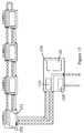
- Figure 2 is an alternate embodiment of the present invention including a
main processor and a remote unit;
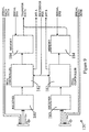
- Figure 3 is a more detailed diagram of Figure 1;
- Figure 4 illustrates a typical communication from the communication hub
to the main processor of Figure 1;
- Figure 5 is a block diagram of a main controller of the main processor of
Figure 1;
- Figure 6 is a detailed block diagram of a field programmable gate array
(FPGA) controller of the main controller in Figure 5;
- Figure 7 is a block diagram of the main processor interface of the
communication hub of Figure 1;
- Figure 8 is a detailed block diagram of a FPGA controller of the interface
in Figure 7:
- Figure 9 is a block diagram of the remote unit interface of the
communication hub of Figure 1;
- Figure 10 is a detailed block diagram of a FPGA controller of the
interface in Figure 9;
- Figure 11 is a block diagram of the interface of a remote camera of
Figure 1;
- Figure 12 is a detailed block diagram of a FPGA controller of the
interface in Figure 11;
- Figure 13 is a star configuration of a number of remote cameras and a
communication hub of the present invention;
- Figure 14 is a bi-directional daisy chain configuration of a number of
remote cameras and a communication hub of the present invention; and
- Figure 15 is a single direction daisy chain configuration of a number of
remote cameras and a communication hub of the present invention.
-
Detailed Description of the Invention
-
In the following detailed description of the preferred embodiment,
reference is made to the accompanying drawings which form a part hereof, and
in which is shown by way of illustration specific preferred embodiments in
which the inventions may be practiced. These embodiments are described in
sufficient detail to enable those skilled in the art to practice the invention, and it
is to be understood that other embodiments may be utilized and that logical,
mechanical and electrical changes may be made without departing from the spirit
and scope of the present inventions. The following detailed description is,
therefore, not to be taken in a limiting sense, and the scope of the present
inventions is defined only by the appended claims.
-
The digital serial link (DSL) of the present invention is a vision control
system having hi-directional serial communications bus for transmitting digital
data and control signals between remote video cameras and a main processor.
The digital video data can be used by the main processor to generate a response
based on the content of the video data. That is, the main processor can include a
means for analyzing the video data so that the DSL can operate in a machine
vision or image processing system.
-
In the preferred embodiment, shown in Figure 1, the DSL system has a
main processor 100 and remote units 102, 106 which are connected to the main
processor through a primary communication hub 104. The remote units can be
video cameras 102, or input/output devices such as sensors, controls or strobe
lights, generally referred to as remote units 106. Other remote units are
contemplated including, but not limited to, personal computers, devices
connected with RS232, programmable logic controllers and industrial control
networks. It will be understood that any remote unit capable of receiving signals
and generating output signals can be used in the present system. The primary
hub 104 can also communicate with one or more secondary hubs 108. The
secondary hubs function in a similar manner as the primary hub and are
connected to additional remote units to thereby increase both the system's total
capacity of remote units and the distance between remote units and the main
processor. Distances of up to 250 feet can be achieved using low cost twisted
pairs of wires between a primary hub and either a secondary hub or a remote
unit. This distance can be greatly increased using higher cost links such as fiber
optic lines. The primary hub multiplexes data from the remote units and
secondary hubs into a serial data stream connected to the main processor 100
over communication link 101. The primary hub also distributes and processes
the data transmitted from the main processor to the appropriate remote unit.
-
The communication link 101 between the main processor 100 and the
primary hub 104 is preferably two twisted pairs of wires, with one pair being
used for transmissions from the main processor to the primary hub and the other
pair used to transmit from the primary hub to the main processor. Alternatively,
fiber optic, coax cables or other communication media such as radio
transmissions can be used for the communication link. The use of two separate
data paths allows for independent and simultaneous communication in either
direction, thereby providing the option of controlling a camera while monitoring
the video signal transmitted by that camera. Alternatively, such duplex
communication can be achieved with frequency multiplexing or other such
techniques.
-
In an alternate embodiment where only one remote unit is used, as shown
in Figure 2, one remote unit, eg. a camera 102, can be connected directly with a
main controller 110 of the main processor 100. The communication link 114 in
this configuration comprises two twisted pairs, one pair for each communication
direction and a pair of power supply lines (or similar communication connection
for a different type of remote unit) to exchange digital video signals from the
camera and control signals from the main processor.
-
Referring to Figure 3, the preferred embodiment is shown in further
detail. The main processor 100 has a main controller 110 for transmitting data to
the primary hub and receiving data transmitted by the primary hub over link 101.
The primary hub 104 has a main controller interface circuit 118 for transmitting
data to the main processor and receiving data from the main processor. A
plurality of remote unit interface circuits 120 connect the remote units 102, 106
and secondary hubs 108 to the primary hub 104. Each remote camera has an
interface circuit 112 for processing data transmitted to and received from a hub.
Direct input/output device 122 can communicate to the hub 104 directly without
using a high speed serial link. These I/O devices can provide data directly to the
hub which may then be used or further transmitted over the DSL.
-
The secondary hubs 108 are similar to the primary hub in that they have
an interface circuit 118 for communication with the primary hub 104 and remote
unit interface circuits 120 for communication with remote units. Before
describing the interface circuits of the main processor 100, primary hub 104 and
remote units, the protocol of digital serial transmissions in the system is
described.
Communication Protocol
-
Referring to Figure 4, data is communicated between the primary hub,
the main processor and the remote devices using two distinct formats; a control
packet, and a data packet. The control packet is a fixed length transmission used
to provide control data. This control data can contain control information from
the main processor which is directed to a remote unit to control, for example, a
video camera. The control packet can be used to control operating features of
the video camera such as gain, offset, shutter speed, zoom, focus, and iris
aperture. The control packet can also contain requests from a remote unit for a
particular service, for example, a camera may request that a strobe light be
activated to assist in obtaining a video image. The control packet is preferably
81 bits long comprising nine bytes (bits 1-8) and an appended ninth bit as shown
in Table 1.
| Bit 9 | Bits 8 - 1 |
| 1 | Start of control packet |
| 0 | Source Address |
| 0 | Destination Address |
| 0 | (1 bit) priority code/ (7 bit) device type |
| 0 | (3 bits) spare / (5 bit) data type |
| 0 | Data type index |
| 0 | Real Time Clock (lower byte) |
| 0 | Real Time Clock (upper byte) |
| 1 | End of control packet |
-
The ninth bit is used as a signaling bit to identify the transmission of control
codes. A logical 1 indicates that a control code is included in the accompanying
byte. The start of control packet is indicated by a unique identifier control code
used to notify the receiver that a control packet is being transmitted. A different
unique identifier can be used to indicate a high priority transmission, as
described in greater detail below. That is, a high priority transmission and a
standard priority transmission would have different "start of control packet"
indicators. The second byte of the control packet contains the address of the
original transmitting source of the control packet and the third byte contains the
address of the final destination of the packet. A one bit priority code is included
in the fourth byte of the control packet to indicate the priority of the
communication. If the priority bit is a logical 1 the communication is high
priority and a logical 0 indicates low priority. The remaining seven bits of the
fourth byte are used to identify the type of device transmitting data, for example,
a digital camera, line scanner or I/O device. The next byte contains five bits
identifying the type of control being transmitted, for example, camera control.
Three spare bits are also included in this byte. The data type index byte provides
a detailed description of the control process desired. If the data type indicates a
camera control, the data type index can be used to reset the camera, trigger the
camera, or start and stop the transmission of video data. The data type and data
type index can be considered a category and subcategory, respectively, thereby
providing a means to communicate a multitude of control commands and
requests. The real time clock is a 16 bit word contained in two bytes and used to
identify the time in which the transmission was initiated. The real time clock
can be used to monitor the efficiency of the DSL system by tracking the elapsed
time between transmission and receipt. The last byte is a unique control code to
identify the end of the control packet transmission.
-
The second communication format, a data packet, is used to provide
variable length data from the transmitting device. In a transmission originating
in a remote unit, such as a video camera, the data is preferably a video image.
Alternatively, in a transmission originated at the main processor, the data is
preferably information needed by a remote unit. The data packet can contain up
to 2048 bytes of data in addition to 12 bytes of control information. The data
packet format is illustrated in Table 2.
| Bit 9 | Bits 8-1 |
| 1 | Start of data packet |
| 0 | Source address |
| 0 | Destination address |
| 0 | Priority (1 bit) / device type (7 bits) |
| 0 | Data type (5 bits) / data length (3 bits) |
| 0 | Lower 8 bits of data length |
| 0 | Real time clock (lower byte) |
| 0 | Real time clock (upper byte) |
| 1 | Start of data |
| 0 | Data |
| 1 ...... 2,048 bytes |
| 1 | End of data |
| 0 | Cyclic redundancy check (lower byte) |
| 0 | Cyclic redundancy check (upper byte) |
| 1 | End of data packet. |
-
The first four bytes of the data packet are similar to the first four bytes of the
control packet. As with the data transmissions, a separate unique identifier can
be used to indicate a high priority transmission. Therefore, a high priority
transmission and a standard priority transmission would have different "start of
data packet" indicators. The tree spare bits of the fourth byte in the control
packet are used in the data packet as the upper three bits of an 11 bit word used
to indicate the length of the data being transmitted. The ninth bit of the data
packet marks the transmission of a control code with a logic 1. The ninth bit and
a unique control code are used to indicate the beginning of the data transmission.
The data transmission can vary from one byte to 2048 bytes. The length of the
transmission is primarily dependent upon the type of device transmitting. That
is, as seen in Figure 4, standard RS-170 video and double speed video transmit
different length data packages as a result of the resolution of the video image
captured by each type of video camera. Following the data transmission the
ninth bit and a unique control code are used to indicate the end of the data
transmission. Two bytes are used for a cyclic redundancy check (CRC). The
last byte contains unique control code to signal the end of the data packet
transmission.
-
To avoid erroneously processing transmissions from a remote unit, the
ninth bit and a unique 'no-operate' code can be transmitted from the remote unit
which indicates that the unit is not transmitting valid signals. This code,
therefore, allows a remote unit to stop transmitting valid signals without
confusing the receiver. When a receiver receives the no-operate code it remains
in a hold state waiting for the no-operate code to end and valid signals to
continue.
-
CRC is a standard data communication error detection technique
incorporating the generation of a code at the transmission and the second
generation of the code at the receiver using the transmitted data. The receiver
compares the transmitted CRC and the second generated CRC to determine if
errors occurred. A further description of CRC can be found in Cypress
Semiconductor Applications Hand Book (April 1994) at 5-105. It will be
understood by one skilled in the art that alternate error detection and correction
techniques can be used.
-
The priority bit of both packets can be used to send urgent transmissions
over the DSL. The primary hub typically multiplexes transmissions on a first-in
first-out basis. If a high priority packet is transmitted to the hub, however, the
hub will insert the packet into a currently transmitted packet. The receiving
circuitry will trigger on the ninth bit signal and the unique identifier codes to
retrieve the high priority packet without missing any data from the currently
transmitted packet. As illustrated in Figure 4, during the transmission of an RS-170
color video data packet, transmission is interrupted and a high priority
control packet is inserted in the data stream, after which the remaining data
packet is transmitted. Real-time control of remote devices can, therefore, be
achieved. To assist the receiving circuitry in detecting the presence of a high
priority packet, the start control packet byte and start of data packet can be used
to indicate the transmission of a priority packet, as described above.
-
Table 3 illustrates an alternative control packet which eliminates the
priority bits. All control packets are therefore treated as high priority. The start
of control packet identifier, however, can be used to identify super high priority
packets if necessary. Two CRC bytes have been added to the control packet to
allow for better error checking. Table 4 is an alternate data packet.
| Bit 9 | Bits 8 - 1 |
| 1 | Start of control packet |
| 0 | Destination Address |
| 0 | (5 bit) data type / (3 bits) spare |
| 0 | Data type index |
| 0 | Real Time Clock (upper byte) |
| 0 | Real Time Clock (lower byte) |
| 0 | Source Address |
| 0 | CRC (upper byte) |
| 0 | CRC (lower byte) |
| 1 | End of control packet |
| Bit 9 | Bits 8-1 |
| 1 | Start of data packet |
| 0 | Destination address |
| 0 | Data type (5 bits) / data length (3 bits) |
| 0 | No. Of Data Bytes |
| 0 | Real time clock (upper byte) |
| 0 | Real time clock (lower byte) |
| 0 | Source Address |
| 1 | Start of data |
| 0 | Data |
| 2 ...... 2,048 bytes |
| 1 | End of data |
| 0 | Cyclic redundancy check (upper byte) |
| 0 | Cyclic redundancy check (lower byte) |
| 1 | End of data packet. |
-
Table 5 illustrates a short data packet which allows small amounts of data
to be sent. The data is limited to 16 bytes. The short data packet can be useful
for transmitting Input/Output data, configuration data, or status data.
| Bit 9 | Bits 8-1 |
| 1 | Start of data packet |
| 0 | Destination address |
| 0 | Data type (5 bits) / data length (3 bits) |
| 0 | No. Of Data Bytes |
| 0 | Real time clock (upper byte) |
| 0 | Real time clock (lower byte) |
| 0 | Source Address |
| 1 | Start of data |
| 0 | Data |
| 2 ...... 16 bytes |
| 1 | End of data |
| 0 | Cyclic redundancy check (upper byte) |
| 0 | Cyclic redundancy check (lower byte) |
| 1 | End of data packet. |
Main Controller Interface Circuitry
-
Referring to Figures 5-6, the main controller 110 of the main processor
100 is described in detail. As described above, the main controller 110 connects
the primary communication hub 104 to the main processor. That is, the main
controller is an interface between the main processor and the rest of the DSL
system. The controller 110 transmits control and data packets to the DSL and
receives and stores packets for retrieval by the main processor. The control
packets transmitted to the DSL could, for example, be used to enable different
remote cameras, trigger cameras, request digital video outputs, or run built-in-self-tests
(BIST) on the remote units. The control commands available are
limited only by the type of remote units implemented and the above examples
are not intended to limit the commands available for transmission from the main
controller.
-
In the up-stream (toward the remote unit) direction, the main processor is
connected to a DSL control circuit 130 to process upstream packets. The control
130 regulates upstream transmissions and provides the packets to transmitter 132
which transmits to a primary hub 104 over link 101. The preferred transmitters
of the present system are HOTLink™ CY7B923 transmitters manufactured by
CYPRESS Semiconductor Inc., San Jose, California. For detailed information
and operation see HOTLink™ User's Guide (May 1994). In the down-stream
direction transmissions are received from a primary hub by receiver 134 and
processed by a field programmable gate array (FPGA) 136. It will be understood
that a gate array or similar circuitry could be used in place of an FPGA. The
preferred receivers of the present system are HOTLink™ CY7B933 receivers
manufactured by CYPRESS Semiconductor Inc., San Jose, California. For
detailed information and operation see HOTLINK User's Guide (May 1994).
The transmissions received will typically be data packets including digital
camera video and digital inputs, but other data transmissions are contemplated.
The FPGA strips the header and CRC information from the received control and
data packets. The video or input data is stored in memories 138, 140, 142 for
access by the main processor either directly or through the FPGA. The
memories are preferably synchronous dynamic random access memories
(SDRAM), but can be any type of memory including video random access
memories (VRAM).
-
The FPGA 136, as seen in Figure 6, comprises a header decoder 144 for
stripping the header and CRC generator 145 for generating the CRC code from
received transmissions. The header preferably comprises the source address,
destination address and the priority code of either the control or data packets.
The CRC from the received transmission is accessible by the main processor
through buffer 146 to check for errors in the received transmission. A copy of
the header information is also stored in a buffer 146 for access by the main
processor 100. Address decoder 150 is used to identify the address of the buffer
which the main processor is accessing. First-in first-out (FIFO) buffer 148
provides an overflow protection for transferring the digital data to memories 138,
140, 142. The address decoder 150, memory select 152, memory address/timing
154, and refresh/memory control 156 circuits provide management control
capabilities for the memories. The main processor, therefore, can select which
memory is to be used for storing the received data.
Primary Hub Interface Circuitry
-
The primary hub 104 comprises a main processor interface 118 and a
plurality of remote unit interfaces 120. Figures 7 and 8 illustrate block diagrams
of the main processor interface 118. In the up-stream direction, transmissions
from the main processor 100 are received by receiver 158 and processed at
FPGA 160. An up-stream transmission intended for remote units is further
transmitted by transmitter 162 through buffer 164 to all the remote units
connected to the primary hub.
-
The FPGA controller 160, of Figure 7, of the main processor interface
has an input header decoder 166 to strip the header from the transmission and
store the transmission in FIFO buffer 168. Processor interface 170 determines if
the primary hub is the destination address of the transmission. If the hub is the
destination address, the transmitted data and header are processed and the
desired operation indicated in the packet is conducted by the hub. If the hub is
not the final destination, the received transmission is queued in buffer 172 and
re-encoded in encoder 174. Down-stream transmissions are processed at
processor interface 170 in substantially the same manner as up-stream
transmissions. If the main processor is the intended destination, data transfer
unit 176 transmits the signal to the main processor 100 through transmitter 178.
I/O interrupt circuit 222 monitors direct I/O devices 122 and couples their
outputs to the DSL. A power supply 181 is included in the primary hub to
provide power to the remote units.
-
Each remote unit interface 120 preferably interfaces with two remote
units, as shown in Figure 9. The remote unit interfaces are modular such that
additional remote unit interfaces can be added to a hub to increase the number of
remote units connected to the hub, see Figure 3. The modular nature of the
interfaces allows for easy expansion as a system increases in size. Up-stream
transmissions merely pass through the interface and are not further processed. In
the down-stream direction, however, the remote unit interface 120 has a receiver
180, FPGA controller 182 and a memory 184 associated with each remote unit
interfaced. The FPGA 182 and memory 184 operate substantially the same as
FPGA 136 and memories 138, 140, 142 of the main controller 110. The
memories allow for the acquisition of multiple images at one time. In addition,
the memories buffer data rate differences between input and output. Prior art
systems can only acquire images from a limited number of cameras at one time
and therefore inhibit image acquisition from other cameras connected to the
system. This is a problem where the image may change during the time the
camera is inhibited. Memory 184 allows the cameras to acquire an image
without delaying the acquisition. The FPGA 182, as seen in Figure 10, has a
decoder 186 which strips the header from the received transmission and stores a
copy of the header in buffer 188. The received transmission is placed in FIFO
buffer 190 for storage in memory 184. The hub processor 220, Figure 7, can
address buffer 188 using address decoder 192. The hub processor can also
control memory 184 through memory control circuit 196 and memory
address/timing circuit 194.
Camera Interface
-
The following is the preferred embodiment for a remote unit comprising
a video camera 102. Referring to Figures 11 and 12, the camera has an interface
112 which contains a receiver 198 for receiving transmissions from the primary
hub 104 and a transmitter 202 for transmitting to the primary hub. The interface
is preferably a separate circuit which can be used with a plurality of different
cameras. An alternative embodiment provides cameras containing the interface
circuitry. The FPGA controller 200 controls both reception and transmission for
the camera. Regulator 206 regulates power supplied by the power supply 181 of
the primary hub. Analog to digital convener 204 converts an analog video signal
generated by the camera into a digital video signal for transmission to the
primary hub.
-
The FPGA 200 comprises a header decoder 208 for decoding the header
and determining if the camera is the intended destination of the received signal.
Preferably each remote unit has both a unique address and a global address for
receiving transmissions. The unique address is used for a particular unit, while
the global address is used for all of the remote units. If either address is
detected, the FPGA processes the signal. A built in self test circuit 210 provides
the ability to test the camera and transmit the results to the primary hub. To
transmit digital video data from analog to digital converter 204. CRC generator
212 produces the CRC code bytes used in the transmitted data packet, as
explained above, and encoder 214 encoded the header for the transmission.
Horizontal timing generator 216 and vertical timing generator 218 are used to
remotely adjust the timing of the camera depending on the type of camera used.
It will be recognized that additional operating characteristics of the camera can
be remotely controlled by the DSL system. Figure 13 illustrates one preferred
configuration of remote cameras. A plurality of cameras, cameras 1-4, are
arranged in a star configuration. That is, each camera has a separate
communication link to the primary hub 104 and is independent of the other
cameras. Figure 14 illustrates an alternative configuration of remote cameras. A
plurality of cameras, cameras 1-4, are arranged in a bi-directional daisy chain
configuration. That is, the communication hub communicates with the cameras
over a common link. Figure 15 illustrates another alternate configuration of
remote cameras. A plurality of cameras, cameras 1-4, are arranged in a single
direction daisy chain configuration. That is, the communication hub transits to
one camera and receives from a different camera, with each camera connected in
series.
-
Alternately, one skilled in the art will recognize that analog video
cameras can be used to transmit to a primary or secondary hub using analog
signals. Because the signals are analog, no analog-to-digital circuitry is needed
at the camera. The analog signal is transformed into the digital signal as
described above at the remote unit interface 120. In this embodiment, the remote
unit interface 120 comprises components comparable to the converter 204, CRC
generator 212 and the encoder 214 as described above. This embodiment allows
for the economical use of analog cameras by not requiring a user to purchase
digital camera interfaces. Further, both analog and digital cameras can be used
in combination in a DSL.
Operation of the DSL System
Remote Camera communication
-
The DSL communication and control system as described above and
shown in Figure 1 provides communication between remote units 102, 106, at
least one communication hub 104 and a main processor 100. The operation of
the communication system is best understood by first examining the down
stream communication from a remote video camera 102.
-
The camera interface 112 of Figures 11 and 12 receives analog video
signals from the remote video camera 102 and converts the analog signal to
digital using converter 204. Converting the analog signal to digital allows
flexibility in camera selection. Different cameras can be used or exchanged
without requiring extensive changes in cable connections as with a conventional
system. Further, the horizontal and vertical timing generators 216, 218, as
described in further detail below, allow for the use of different cameras without
changing the camera interface 112. The digital video signal is received at FPGA
controller 200 where the CRC generator 212 generates the CRC bytes of the data
packet as shown above in Table 2. The digital video data and CRC are
combined at the header encoder 214 to generate data packets as shown in Table 2
above. Alternatively, the FPGA controller 200 can generate control packets as
previously shown in Table 1. These control packets preferably request that
either the primary hub 104 or the main processor 100 perform some function,
such as trigger a strobe light 106. The communications from the controller 200
are transmitted to the primary hub 104 via transmitter 202. The conductor cable
between the remote video camera 102 and the primary hub 104 is shielded and
preferably comprises six conductors; two for serial communication to the hub,
two for serial communication from the hub and two power supply lines.
-
Referring to Figures 7 through 10, the transmitted packets from each
camera are received at the primary hub by receiver 180 and processed by FPGA
controller 182. The header of the packet is decoded at header decoder 186 and a
copy of the header is stored in buffer 188. The received packet is stored in the
FIFO buffer 190 prior to being stored in the memory 184. Address decode 192
allows the hub processor 220 to read and control buffer 188, and control the
storage of the packet to the memory 184. I/O interrupt control circuit 222
monitors interrupt requests from a plurality of interrupt lines INT A through INT
H associated with the plurality of remote units. As stated above, I/O interrupt
control circuit 222 monitors direct I/O devices 122. If an I/O device sends a
signal to the hub, a specific response or operation may be started. For example,
a direct sensor may send a signal indicating that a camera acquire a picture. In
response the hub will send command to the camera to take a picture. The camera
will then respond back to the hub and request that a strobe be triggered.
-
If a transmission from a remote unit is received by the primary hub a
signal is provided on the corresponding interrupt line and the control circuit 222
determines if the transmission is a high priority. A high priority signal is
processed as described above such that a standard transmission is interrupted
temporarily. If a high priority control packet is received from a video camera
requesting that a strobe light be triggered, the primary hub immediately transmits
a strobe trigger signal to the strobe 106 associated with the requesting camera.
-
The hub processor 220 controls the multiplexing of the data stored in the
memories 184 of the remote unit interfaces 120 to the FPGA controller 160. As
seen in Figure 8, the processor interface 170 takes the output from the hub
processor 220 and relays the data to the high speed data transfer circuit 176. The
digital serial packet is then transmitted to the main processor by transmitter 178
via cable link 101 at 330 Mbps (mega bits per second), however, speeds of 660
Mbps can be used. It will be understood that in speeds in excess of one giga bits
per second are contemplated.
-
The transmission is received by the main controller 110 of the main
processor 100 at receiver 134. The header of the received transmission is
decoded at decoder 144 and a copy of the header is stored in the buffer 146. The
CRC code for received data packets is decoded at decoder 145 and a copy is also
stored in buffer 146. The received packet is stored in FIFO buffer 148 prior to
storage in one of the memory 138, 140, 142. Address decoder 150 allows the
main processor 100 access to the header and CRC stored in the buffer 146. The
main processor also controls the storage of the packets to the memory using
circuits 152, 154, and 156. The main processor evaluates the received CRC code
to determine if an error occurred in the transmission.
-
As seen in Figure 1, secondary hubs 108 can be used to increase the
number of remote units serviced by one main processor and increase the distance
between a remote unit and the main processor. This hierarchical structure is
implemented using the same principles as the primary hub, except the secondary
hub will multiplex the remote units serviced thereby to the primary hub.
-
As can be seen, the present invention provides a communication and
control system for receiving data and control requests from a plurality of remote
units. Remote units which require immediate attention can be controlled without
substantially interrupting communication with other remote units, thereby
allowing image acquisition from an unlimited number of video cameras.
Communication hubs can be used to respond to some of the control requests
from the remote units to reduce the transmissions to the main processor and
increase the speed of the system. Real-time control can, therefore, be obtained.
As will be seen below, the main processor can receive data from a camera while
simultaneously controlling that camera.
Main processor communication
-
The communication and control of upstream packets from the main
processor is best understood starting with Figure 3. A transmission originating
at the main processor 100 is transmitted over the communication link 101 to the
primary hub 104. If the intended receiving address is the primary hub, the
transmission stops there. If, however, a remote unit 102 is the destination
address, the transmission is broadcast to all remote units and the intended unit
acts upon the received transmission.
-
Referring to Figures 5, 7-9, a communication packet originating at the
main processor is transmitted over the communication link 101 to the primary
hub 104 via the DSL control 130 and the transmitter 132. Receiver 158 of the
main controller interface 118 receives the transmission packets and relays the
packets to the FPGA controller 160. The headers of the packets are decoded by
decoder 166 and the headers and data are stored in FIFO buffer 168. Each
decoded header is evaluated at processor interface 170. If the hub is the
destination address of the communication, the requested action is performed by
the hub processor. If, however, the destination address is not the hub, the
decoded header is transferred to the header encoder 174 through data buffer 172.
The re-encoded header and data are transmitted using transmitter 162 and buffer
164 to all of the remote units over serial data lines OUT A through OUT H.
Upstream transmissions effectively bypass the remote unit interfaces 120 to
connect with the serial data conductor lines associated with each remote unit.
-
The receiver 198 of each remote camera 102 captures the up-stream
transmissions and decoder 208 decodes the header. If the destination address
matches an address of the remote unit the command code is followed. If the
address does not match, the transmission is ignored. Each remote unit as
described above preferably has a unique address and a global address such that
remote units can be addressed individually or simultaneously. The command
code can indicate a variety of desired operations, in particular a camera could run
a self test using self test circuit 210 or the horizontal and vertical timing can be
adjusted using generators 216 and 218. It will be understood that a variety of
operations can be controlled remotely, and are not intended to be limited to those
described.
-
As can be seen, the present invention provides a communication and
control system for transmitting data and control commands to a plurality of
remote units. The main processor can control either the remote units directly, or
instruct the primary or secondary hubs to perform a specified operation. Control
operations can be distributed to increase efficiency and communication speed.
Real-time communication and control can, therefore, be obtained. The main
processor can receive data from one camera while simultaneously controlling
another camera.
Conclusion
-
The present invention provides a high speed digital serial communication
and control system, and corresponding methods of operation, for use in machine
vision systems. The invention allows for real-time remote control of cameras
and other input/output devices. The digital transmission of video data can
include data error checking and has more noise immunity than conventional
systems. The present invention uses simpler cheaper cables, increases the
distance between the remote units and a main processor, allows for the easy
mixing of camera types and provides the option of expanding the system by
adding additional secondary hubs and cameras. The present invention simplifies
the main processor and allows for the simultaneous acquisition of images from a
plurality of remote video cameras. The invention allows a plurality of remote
units to communicate with a main processor either with or without an
intermediate communication hub. The remote units can be video cameras
transmitting digital signals. Video Cameras transmitting analog signals can be
used, provided an intermediate communication hub is also used.
-
Additional refinements can be included in the system without departing
from the invention. For example, if a packet is received by a hub which is not
the destination address, the packet will be forwarded without interrupting the hub
processor. Further, hubs can be prevented from communicating directly with
another hub. In this system each hub will communicate a packet to the main
processor which will forward the packet to the appropriate destination hub. It
will be appreciated that packets may pass through an intermediate hub on the
way to the processor or to the destination hub. Finally, handshaking can be
added between the system devices to reduce communication errors.