EP0984390A2 - Apparatus for providing location information in a multidimensional address space - Google Patents
Apparatus for providing location information in a multidimensional address space Download PDFInfo
- Publication number
- EP0984390A2 EP0984390A2 EP99306875A EP99306875A EP0984390A2 EP 0984390 A2 EP0984390 A2 EP 0984390A2 EP 99306875 A EP99306875 A EP 99306875A EP 99306875 A EP99306875 A EP 99306875A EP 0984390 A2 EP0984390 A2 EP 0984390A2
- Authority
- EP
- European Patent Office
- Prior art keywords
- address
- glyph
- glyphs
- computer
- code
- Prior art date
- Legal status (The legal status is an assumption and is not a legal conclusion. Google has not performed a legal analysis and makes no representation as to the accuracy of the status listed.)
- Granted
Links
Images


Classifications
-
- G—PHYSICS
- G06—COMPUTING; CALCULATING OR COUNTING
- G06K—GRAPHICAL DATA READING; PRESENTATION OF DATA; RECORD CARRIERS; HANDLING RECORD CARRIERS
- G06K19/00—Record carriers for use with machines and with at least a part designed to carry digital markings
- G06K19/06—Record carriers for use with machines and with at least a part designed to carry digital markings characterised by the kind of the digital marking, e.g. shape, nature, code
- G06K19/06009—Record carriers for use with machines and with at least a part designed to carry digital markings characterised by the kind of the digital marking, e.g. shape, nature, code with optically detectable marking
- G06K19/06037—Record carriers for use with machines and with at least a part designed to carry digital markings characterised by the kind of the digital marking, e.g. shape, nature, code with optically detectable marking multi-dimensional coding
-
- G—PHYSICS
- G06—COMPUTING; CALCULATING OR COUNTING
- G06K—GRAPHICAL DATA READING; PRESENTATION OF DATA; RECORD CARRIERS; HANDLING RECORD CARRIERS
- G06K7/00—Methods or arrangements for sensing record carriers, e.g. for reading patterns
- G06K7/10—Methods or arrangements for sensing record carriers, e.g. for reading patterns by electromagnetic radiation, e.g. optical sensing; by corpuscular radiation
- G06K7/14—Methods or arrangements for sensing record carriers, e.g. for reading patterns by electromagnetic radiation, e.g. optical sensing; by corpuscular radiation using light without selection of wavelength, e.g. sensing reflected white light
- G06K7/1404—Methods for optical code recognition
- G06K7/1439—Methods for optical code recognition including a method step for retrieval of the optical code
- G06K7/1443—Methods for optical code recognition including a method step for retrieval of the optical code locating of the code in an image
Definitions
- This invention relates to the construction of multi-dimensional address spaces and, more particularly, to self-clocking and address carpet glyph instantiations of such address spaces and disambiguation techniques for address carpets.
- Glyphs are often encoded by respective elongated slash-like glyphs written on a two- dimensional, spatially periodic pattern of centers in accordance with a predetermined spatial formatting rule, with the individual glyphs being tilted to the left and right of vertical by approximately +45° and -45° for encoding logical "0's" and "1's", respectively.
- the mutual orthogonality of the glyph encodings for the two logical states of these single bit digital quanta enhances the discriminability of the code sufficiently to enable the embedded information to be recovered, even when the code pattern is written on a sufficiently fine grain pattern of center to cause the code pattern to have a generally uniform grayscale appearance.
- address spaces may be constructed by encoding cyclical pseudo-noise digital bit sequences (sometimes referred to as "PN sequences") and other types of maximal length-like digital bit sequences (i.e., sequences of length, L, in which every N-bit long subsequence is unique) in two dimensional spatially periodic self-clocking glyph code patterns.
- PN sequences cyclical pseudo-noise digital bit sequences
- L maximal length-like digital bit sequences
- One of the unifying themes of these prior proposals is that they recommend constructing two dimensional address spaces by mapping at least two bit sequences of the foregoing type into such a code pattern so that these bit sequences are encoded to propagate in predetermined directions along respective non-parallel lines of glyphs.
- bit sequences need not be mapped into the code pattern in alignment with the principal axes thereof, it often is desirable to employ such mappings to reduce the computations that are required to determine the relative addresses of the glyphs in standard Cartesian coordinates (i.e., "x" and "y” parameters expressed in units of glyphs).
- the encodings of these bit sequences may completely or partially span the glyph code pattern, so it is to be understood that the addressing that is afforded by them is effective only within that portion of the glyph code pattern that projects onto both of the encodings.
- mappings may be mapped into the glyphs on these non-parallel lines at unitary or fractional duty ratios, but it has been recognized that mappings preferably are spatially cyclical for applications in which it is desired to compute relative addresses for glyphs within the address space.
- Every bit in a maximal bit length sequence resides at a predetermined uniquely determinable logical position within the sequence. Accordingly, an ordered index of integers is commonly employed to distinguish those bits from each other on the basis of their respective ordinal logical positions within the sequence.
- These positionally dependent index numbers can, of course, be employed for selectively addressing the glyphs which encode the bits of such a sequence.
- addressing information in at least one additional dimension is required to uniquely identify the spatial locations of those glyphs or any other glyphs that are included within a two dimensional glyph code pattern.
- These unique identifiers of the individual glyphs are referred to as "absolute addresses" because they identify the unique locations at which the individual glyphs reside within the glyph code pattern.
- the spatial address (i.e., the absolute address) of almost any given glyph in an address space of the foregoing type is identifiable, at least to a first approximation, by a metric which specifies the offset distances (if any) between the nominal center of the given glyph and the non-parallel lines of glyphs that encode the respective maximal length bit sequences, where these offsets are measured parallel to the principal axes of the code pattern and are expressed in units of glyphs.
- the above-described metric reduces to an x/y coordinate pair which identifies the spatial location of the given glyph with substantial precision in a standard Cartesian coordinate system.
- the intersections of the lines on which these maximal bit length sequences are encoded tend to restrict the freedom of design choice if there are glyphs at any of these intersections.
- the solution that has been proposed for this special class of code patterns is to encode a maximal length bit sequence (or a combination of interleaved, relatively prime maximal length bit sequences) in the glyphs in a raster-like pattern which is selected to cause the logically ordered bits of the sequence to spatially propagate from side-to-side along a known dimension (say, the width) of the code pattern which more gradually propagating along the other (e.g., the height) of the code pattern in, say, top-to-bottom order.
- This raster encoding of the maximal length bit sequence effectively "folds" the bit sequence into the code pattern module a known or computable number of glyphs (i.e., the number of glyphs that the code pattern contains along its known dimension).
- the spatial address of any given glyph within the code pattern can be computed in x/y coordinate space from the sequence index number of the bit that is encoded by the glyph by dividing the sequence index number of the bit by the known glyph count/line modules.
- Human interpretable textual, graphical or mixed textual and graphical representations of the files that are accessible via this user interface are spatially registered in superimposed or juxtaposed relationship with respective addresses in this address space. These spatial addresses, in turn, are logically registered in a lookup table or the like with computer recognizable descriptions of the respective file names and, if needed, paths to the directories for the named files.
- a more or less conventional self-clocking glyph code pattern 21 which is composed of elongated slash-like marks or "glyphs" 22 and 23 that are written on a generally regular rectangular lattice of centers on a suitable recording medium 24.
- the glyphs 22 and 23 are printed by a printer (not shown) operating at 300 d.p.i. - 600 d.p.i. to write 4 pixel x 4 pixel - 7 pixel x 7 pixel representations of the glyphs 22 and 23 on regularly spaced centers that are distributed widthwise and lengthwise of the recording medium 24 to produce the rectangular code pattern 21.
- the glyphs of these fine grain glyph code patterns are not easily resolved by the unaided human eye when the code patterns are viewed under standard lighting conditions and at normal reading distances, so the code pattern 21 typically has a generally uniform gray scale appearance. Nevertheless, the glyph code is still capable of effectively communicating machine readable digital information.
- the glyphs 22 and 23 usually are titled to the left and right, at about +45° and -45° with respect to the longitudinal dimension of the recording medium 24 to encode binary "1's" and "0's", respectively, as shown at 25.
- the address space fragments 85-91 may be written directly on the objects 105-111, respectively, and/or on other substrates that are subsequently permanently or temporarily affixed to the objects. While a two dimensional address space can be employed for this application, more fully parameterized address spaces, such as the labeled address spaces AL 1 ... AL n have the advantage of having a hierarchical organization which may be employed, as shown, to hierarchically organize object identifiers 85-91 by object type or any other desired classification.
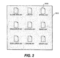
- Fig. 2 is a block diagram that shows an example graphical user interface implemented using a glyph address carpet.
- the interface comprises two components: (1) sensory indicia and (2) a background which comprises a glyph address carpet 1612.
- the address carpet may be visible or invisible.
- the sensory indicia in Fig. 2 are preferably visual indicia, and in particular graphic elements, such as icon 1610.
- the glyph address carpet 1612 is used as the background wallpaper for the graphic elements.
- the glyph pattern that makes up the background is called an "address carpet" because the glyphs can be decoded to provide unique address information for each location.
- the icons may, as shown in Fig. 2, be partially formed by glyphs that are part of the glyph address carpet.
- the indicia may be substantially composed of the glyphs themselves. Because the glyphs encode address information, a portion of the glyphs can be read optically and decoded to determine a unique address for a local position.
- the graphical user interface implemented using glyph address carpets can be implemented on any media capable of displaying the components of the interface.
- the interface could be implemented on hardcopy, such as paper, labels, physical objects, and photographic media; on dynamic displays such as a cathode ray tube (CRT) display or liquid crystal display (LCD); or on projected displays from fixed or dynamic media such as a slide projector, or television.
- CTR cathode ray tube
- LCD liquid crystal display
- projected displays from fixed or dynamic media such as a slide projector, or television.
- the embodiment described herein utilizes glyphs
- the glyphs can alternatively be replaced by any system, visible or invisible, that provides a data address code.
- the embodiment described herein utilizes visual indicia
- the visual indicia can alternatively be replaced by any sensory indicia that could serve to guide a user or machine to select a location while the machine readable data address codes provide an address logical reference.
- the embodiment described herein utilizes a paper substrate, but the paper substrate can alternatively be replaced by any media in which the data address codes can be embedded and read by a machine.
- the sensory indicia may be embedded in the same media as the data address codes or may be embedded in other media.
- the sensory indicia can alternatively be projected onto glyphs, or glyphs can be projected onto sensory indicia.
- Fig. 3 is a block diagram of an image capture system that may be used to capture a user-selected portion of a graphical user interface, such as glyph address carpet 12, and decode the glyphs in the captured portion.
- computer system 1712 is a general purpose computer system, such as a conventional personal computer or laptop computer, that includes main memory 1716, read only memory (ROM) 1718, storage device 1720, processor 1722, and communication interface 1724, all interconnected by bus 1726.
- Bus 1726 also connects to display 1730, cursor control 1714, and frame capture 1728.
- Image capture device 1710 which in this case is a camera pen, is connected to frame capture 1728 and mouse 1730.
- Camera pen 1710 transmits image information to frame capture 1728.
- button 1714 of camera pen 1710 is wired to mouse 1730 so that when a user presses button 1714 a signal travels through the circuitry of mouse 1728 to cursor control 1714.
- the signal causes processor 1722 to run a program that directs frame capture 1728 to capture the image from camera pen 1710.
- both the image line and signal line from camera pen 1710 are input directly into frame capture card 1728.
- the lines between camera pen 1710 and computer 1712 can be wired in any way that provides capture of the image from camera pen 1710.
- the user makes a selection by placing camera pen 1710 on or near visual indicia on glyph address carpet 1732, and pressing button 1714.
- Pressing button 1714 causes camera pen 1710 to capture the portion of the address carpet under the tip of camera pen 1710, and transmit the image to computer 1712, via frame capture 1728, for analysis.
- the button or multiple buttons can be used for additional signaling, as in a double click, hold down.
- Fig. 4 shows an embodiment of a user interface implementing hot zones.
- a hot zone is an area on or near the visual indica that defines selection locations that are equivalent to selecting the same visual indicia.
- the hot zone may encompass the visual indicia.
- the icon David's DOC2 has a broken line area indicating a hot zone. If the user makes a selection within this hot zone, the icon "David's DOC2" will be selected. This allows the user to make a selection that is on or near the visual indicia. The selection is treated by the system as if the visual indicia was selected.
- the hot zone may be explicitly denoted by the visual indicia, including a visually distinct coloring in the address carpet, or may be implicit by appropriate proximity.
- Fig. 4 also illustrates a preferred embodiment for the glyph address carpet coding scheme.
- Each glyph is either a forward slash or a backward slash.
- the orientation and spacing of the rows and columns of glyphs is indicated by O GX and O GY , respectively.
- an A code runs on every other line, and is interlaced with a B code.
- every A value is preferably the same.
- every B value is preferably the same.
- Fig. 5 is a block diagram illustrating the selection process using camera pen 1710.
- Each icon has an effective selection area indicated by a broken line hot zone 1910.
- the tip of camera pen 1710 covers an area indicated by 1914.
- the orientation of the tip of camera pen 1710 is denoted by the Y C axis and X C axis.
- the user places the tip of camera pen 1710 over the area to be selected.
- the image within area 1914 is captured.
- Computer 1712 analyzes the captured image to determine the location of the center 1912 of selection area 1914. After determining the location of center 1912, the location of center 1912 is used to look up a function corresponding to center 1912.
- Fig. 6 is a block diagram illustrating a second type of selection process that may be used to implement a graphical user interface consistent with the principles of the invention.
- camera pen 1710 has a pointing device attached to the tip, thus making the image capture area of the pen offset from the location pointed at by the user.
- a user selects the icon "David's DOC" by pointing to the icon, but the camera pen 1710 image capture area 2014, with center 2012, is offset from the icon.
- computer 1712 must determine the actual selection based on 1) the image area 2014, and 2) the orientation of the selected area, and 3) the offset distance and direction from the image capture area from center 2012.
- the offset calculation utilizes the glyph lattice parameters from the captured image decoding process described below.
- main memory 1716 is a random access memory (RAM) or a dynamic storage device that stores instructions executed by processor 1722.
- Main memory 1716 may also store information used in executing instructions.
- ROM 1718 is used for storing static information and instructions used by processor 1722.
- Storage device 1720 such as a magnetic or optical disk, also stores instructions and data used in the operation of computer system 1712.
- Display 1730 may be a CRT or other type of display device.
- Cursor control 1714 controls cursor movement on display 1730.
- Cursor control 1714 may be, for example, a mouse, a trackball or cursor direction keys.
- the system shown in Fig. 3 can be used to implement the glyph address carpet capture and translation system described herein.
- the apparatus and methods described herein may be implemented by computer system 1712 using hardware, software, or a combination of hardware and software.
- the apparatus and methods described herein may be implemented as a program in any one or more of main memory 1716, ROM 1718, or storage device 1720.
- processor 1722 executes programs which analyze captured portions of a glyph address carpet to determine address information encoded in the glyphs.
- Such programs may be read into main memory 1716 from another computer-readable medium, such as storage device 1720.
- Execution of sequences of instructions contained in main memory 1716 causes processor 1722 to perform the process steps consistent with the present invention described herein.
- Execution of sequences of instructions contained in main memory 1716 also causes processor to implement apparatus elements that perform the process steps.
- Hard-wired circuitry may be used in place of or in combination with software instructions to implement the invention. Thus, embodiments of the invention are not limited to any specific combination of hardware circuitry and software.
- Non-volatile memory media includes, for example, optical or magnetic disks, such as storage device 1720.
- Volatile memory media includes RAM, such as main memory 1716.
- Transmission media includes coaxial cables, copper wire and fiber optics, including the wires that comprise bus 1726. Transmission media can also take the form of acoustic or light waves, such as those generated during radiowave and infrared data communications.
- Computer-readable media include, for example, a floppy disk, a flexible disk, hard disk, magnetic tape, or any other magnetic storage medium, a CD-ROM, any other optical medium, punchcards, papertape, any other physical medium with patterns of holes, a RAM, a PROM, an EPROM, a FLASH-EPROM, any other memory chip or cartridge, a carrier wave as described hereinafter, or any other medium from which a computer can read and use.
- Various forms of computer readable media may be involved in carrying one or more sequences of instructions to processor 1722 for execution.
- the instructions may initially be carried on a magnetic disk or a remote computer.
- the remote computer can load the instructions into its dynamic memory and send the instructions over a telephone line using a modem.
- a modem local to computer system 1712 can receive the data on the telephone line and use an infrared transmitter to convert the data to an infrared signal.
- An infrared detector coupled to appropriate circuitry can receive the data carried in the infrared signal and place the data on bus 1726.
- Bus 1726 carries the data to main memory 1716, from which processor 1722 retrieves and executes the instructions.
- the instructions received by main memory 1716 may optionally be stored on storage device 1720 either before or after execution by processor 1722.
- Computer system 1712 also includes a communication interface 1724 coupled to bus 1726.
- Communication interface 1724 provides two way communications to other systems.
- communication interface 1724 may be an integrated services digital network (ISDN) card or a modem to provide a data communication connection to a corresponding type of telephone line.
- ISDN integrated services digital network
- Communication may also be, for example, a local area network (LAN) card to provide communication to a LAN.
- LAN local area network
- Communication interface 1724 may also be a wireless card for implementing wireless communication between computer system 1712 and wireless systems.
- communication interface 1724 sends and receives electrical, electromagnetic or optical signals that carry data streams representing various types of information.
- the link between communication interface 1724 and external devices and systems typically provides data communication through one or more networks or other devices.
- the link may provide a connection to a local network (not shown) to a host computer or to data equipment operated by an Internet Service Provider (ISP).
- ISP Internet Service Provider
- An ISP provides data communication services through the world wide packet data communications network now commonly referred to as the "Internet”.
- Internet Internet
- Local networks and the Internet both use electrical, electromagnetic or optical signals that carry digital data streams.
- the signals through the various networks and the signals between the networks and communication interface 1724, which carry the digital data to and from computer system 1712, are exemplary forms of carrier waves transporting the information.
- Computer system 1712 can send messages and receive data, including program code, through the network(s) via the link between communication interface 1724 and the external systems and devices.
- a server might transmit a requested code for an application program through the Internet, an ISP, a local network, and communication interface 1724.
- Program code received over the network may be executed by processor 1722 as it is received, and/or stored in memory, such as in storage device 1720, for later execution. In this manner, computer system 1712 may obtain application code in the form of a carrier wave.
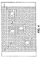
- Fig. 7 illustrates an embodiment of the address codes encoded in the glyph address carpet 1732. More particularly, Fig. 7 illustrates one section 2110 of the glyph address carpet.
- the addresses are encoded by alternating rows of "A" address code sequences and "B" address code sequences. The position along each sequence in each row should be unambiguously determinable from a predetermined length subsequence. For example, an N-bit shift register maximal length code can be uniquely determined in position from an N-bit subsequence.
- Each address code sequence is a fifteen bit sequence, with the A sequence indexed running left to right, and the B sequence indexed running in a reverse direction, right to left.
- Each row of A code sequences is offset by two glyph positions relative to the previous and next row of A addresses.
- each row of B code sequences is offset in the opposite direction by two positions.
- the encoding scheme has two key characteristics: parallel rows including two sets of one-dimensional unique address codes and relative offsets among members of the two sets so that the offset between each pair from the two sets is unique. This establishes two-dimensional unique address locations.
- Computer 1712 decodes address information encoded in the glyphs by analyzing the captured image area in two steps. Ideally, the user places camera pen 1710 over a portion of glyph address carpet 1732 and capture an image angularly aligned as shown in the pattern of bits shown in Fig. 7. In reality, however, the user variably orients the camera pen 1710 over an area of interest, so the pattern could be oriented anywhere from 0° to 360°. Therefore, the computer 1712 must first determine the orientation of the image as part of decoding and interpreting the address information.
- the orientation of the image is determined by analyzing the captured image. This process is called disambiguation. (See, e.g., U.S. Patent No. 5,521,372 to Hecht, et al.). After determining the proper orientation of the image, computer 1712 decodes the address of the selected location in the address carpet. The disambiguation and address decoding processes performed by computer 1712 will now be described in greater detail.
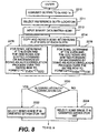
- Fig. 8 and Fig. 9 form a flow chart showing the disambiguation and address decoding processes performed by computer 1712 on the captured image area.
- Computer 1712 begins the disambiguation process by image processing the captured portion of the address carpet to find a glyph seed.
- a glyph seed is a first-identified glyph having readable glyphs around it. Once a glyph seed has been found, the glyph lattice can be determined by processing neighbors of the glyph seed. (See Appendices A and B).
- the glyphs are then decoded as 1's or 0's, which are filled into a binary data matrix having rows and columns corresponding to the glyph lattice rows. The orientation may still be ambiguous with respect to 90° and 180° rotations.
- Fig. 10 illustrates a binary data matrix (BDM) 2310 formed from a glyph lattice captured by camera pen 1710.
- the BDM has locations corresponding to the glyph lattice.
- the size of the BDM corresponds closely to the size of the glyph lattice.
- Each location of the glyph lattice is analyzed to determine which value should be placed in the corresponding location of the BDM.
- the BDM is filled with a value, for example ⁇ , which indicates that no attempt has been made to read the glyph.
- the ⁇ is replaced by a value indicating the result of the glyph analysis.
- a B indicates a border location; an X indicates that no interpretable glyph was found at the corresponding location of the glyph lattice; an E indicates a glyph at the edge of the captured image portion; a 0 indicates a back slash glyph; and a 1 indicates a forward slash glyph.
- the area of the matrix corresponding the captured image is filled with 0's and 1's, the edge is bounded by Es, and the Xs correspond to locations that have no readable glyphs.
- the BDM will generally have a similar pattern, the values will often not be as evenly distributed. For example, a glyph location within the captured image area might result in an X if the glyph has been obliterated.
- step 2210 allows computer 1712 to derive a BDM of 0's and 1's from the captured image, it is uncertain whether the BDM is oriented at 0° (i.e., correctly oriented), 90°, 180°, or 270° relative to the original code pattern in the glyph address carpet from which the image was captured. Until the orientation of the captured image is determined, it is not possible to derive the correct address code from the BDM.
- the orientation could be provided by auxiliary information such as physical system constraints. However, the orientation can be uniquely determined directly from the address codes.
- a reference glyph location is selected (step 2211). This location may be chosen in a variety of ways, but is typically a location which represents the selection. For example, the reference glyph location could be at the center of the BDM.
- BDM1 The original BDM developed from the captured image
- Computer 1712 makes a copy of BDM1 and rotates the copy clockwise 90° to form a second binary data matrix, BDM2 (step 2214).
- BDM2 By rotating BDM1 by 90°, the rows of BDM1 become the columns of BDM2, and the columns of BDM1 become the rows of BDM2.
- all bit values in BDM2 are flipped from 0 to 1, and 1 to 0, because a 45° slash glyph rotated 90° appears as the opposite state of the non-rotated glyph.
- Computer 1712 then performs a correlation separately on the odd and even rows of BDM1 (step 2216) to determine whether code in the rows are staggered forward or backward.
- the correlation is also performed for the odd and even rows of BDM2 (step 2218).
- the correlation is performed over all the rows of each BDM, and results in correlation value C1 for BDM1 and correlation value C2 for BDM2.
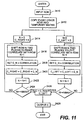
- Fig. 11 is a flowchart showing an embodiment of correlation steps 2216 and 2218 of Fig. 9.
- the process determines a correlation value for every other line of a BDM along diagonals in each direction, and sums the row correlation values to form a final correlation value for the odd or even rows.
- the process is performed on the odd rows of BDM1 to form correlation value C1 ODD for BDM1, the even rows of BDM1 to form correlation value C1 EVEN for BDM1, the odd rows of BDM2 to form correlation value C2 ODD for BDM2, the even rows of BDM2 to form correlation value C2 EVEN for BDM2.
- the BDM that is oriented at 0° or 180° will have a larger C ODD + C EVEN than the other BDM.
- Computer 1712 first inputs the BDM (step 2410), and then copies every other row to a temporary matrix (step 2412). Identical processes are then performed for diagonals to the right and to the left. Steps 2414, 2416, 2418, 2420, 2422 and 2424 process the diagonals to the right. For example, in Fig. 12 the steps correlate along the diagonals moving from the upper left to lower right. First, row count N and correlation value C_RIGHT are each initialized to zero (step 2414). Row N is shifted two places to the right, and correlated with the next row (step 2416). C_N is then set to this value (step 2418). C_RIGHT is then set to C_RIGHT + C_N (step 2420), and N is incremented (step 2422).
- Fig. 11 The steps on the right of Fig. 11 are similar to steps 2414, 2416, 2418, 2420, 2422 and 2424, but process diagonals running from the upper right to lower left to develop correlation value C_LEFT. After correlating the right and left diagonals to determine C_RIGHT and C_LEFT, a final correlation value C is determined by subtracting C_LEFT from C_RIGHT. For example, if odd rows for BDM1 are processed, the C value becomes C1 ODD for BDM1.
- the process steps of Fig. 11 are performed for the odd and even rows of BDM1 and the odd and even rows of BDM2. From this information, the correlation value C1 for BDM1 is set to C1 EVEN + C1 ODD (as determined by Fig. 11 for the rows of BDM1), and the correlation value C2 for BDM2 is set to C2 EVEN + C2 ODD (as determined by Fig. 11 for the rows of BDM1).
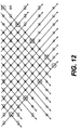
- Fig. 12 illustrates why the correlations determine which way the codes in every other row are shifting.
- the codes along the diagonal starting at A1 in the first position of the second row should have the same value in every other row along the diagonal, except for erasures and errors.
- the codes along the diagonal starting at B1 in the upper right corner should have the same value in every other row along the diagonal, except for erasures or errors. This is true for each value along the diagonal in the odd rows running respectively from B2, B3, ... in the top row.
- the strong correlations along the diagonals running down and to the left on the odd rows and the strong correlations along the diagonals running down and to the right on the even rows indicate that the codes in the even rows are shifting to the right, and the codes in the odd rows are shifting to the left.
- each BDM therefore, four correlation values are developed: 1) odd rows, right to left, 2) odd rows, left to right, 3) even rows, right to left and 4) even rows, left to right.
- the strongest correlation value for the even rows, and strongest correlation value for the odd rows is chosen, and these become C EVEN and C ODD for that BDM (steps 2216 and 2218).
- C EVEN and C ODD are then added to form a final C correlation value for that BDM.
- the BDM with the strongest correlation value is the BDM that is oriented at either 0° or 180° because of the relative orientation of the codes in the odd and even rows.
- step 2230 is performed to determine which direction the code in each line runs (as opposed to which way the code is staggered).
- the codes in the odd lines are staggered in one direction, and the codes in the even lines are staggered in the other. This staggering property of the code, in conjunction with knowing the respective codes that run in the odd lines and even lines, allows determination of the proper 0° orientation of the BDM.
- C1 is greater than C2 (step 2220)
- BDM1 is selected for further processing.
- C1 being greater than C2 indicates that the one-dimensional codes of BDM1 are most strongly correlated and are, therefore, oriented at either 0° or 180° (step 2222).
- C2 is greater than C1
- BDM2 is selected for further processing, because the higher correlation indicates that BDM2 is oriented at either 0° or 180° (step 2224).
- computer 1712 Before determining the address location of the captured image, however, computer 1712 must first determine whether the selected BDM is at 0° (i.e., oriented correctly), or rotated by 180°.
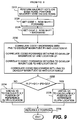
- Fig. 9 is a flowchart showing the steps of how computer 1712 determines the address of the captured area of the glyph carpet.
- bit positions along a diagonal in the BDM when the BDM is oriented at 0°, have the same value at every other row.
- the image capture process and interference from the visual indicia may result in errors and erasures in the BDM data.
- computer 1712 performs a majority vote along each diagonal of the odd rows in the direction the odd rows are staggered, and repeats the majority vote process for even rows along the each diagonal in the direction the even rows are staggered (step 2225). This results in a first code sequence for the odd rows and a second code sequence for the even rows.
- the first and second code sequences should match a subsequence of the original pseudo noise address sequence respectively corresponding to the odd or even set of rows.
- Computer 1712 then retrieves the original pseudo noise address code (Get Code 1) for rows staggered forward (step 2226), and retrieves the original pseudo noise address code for (Get Code 2) for rows staggered backward (step 2228). Using the original pseudo noise address code for each code set A and B, and the code from the majority voting, computer 1712 performs four cross correlations (step 2230) to establishes the best match of the glyph sequence with the PN sequence location for the odd and even rows.
- two adjacent rows of the BDM closest to the reference element chosen in step 2211 are correlated with the respective complete PN sequences that created the original address carpet.
- the PN sequences could be identical.
- a forward and backward correlation is performed for each row.
- the four correlations develop four pairs of peak correlation and position values:
- the calculated X, Y position is then returned (step 2238). Note that diagonals correspond to constant values of U and V, respectively, while rows and columns correspond to constant X and Y. Note also that U and V could be used directly as address parameters.
- an X, Y value associated with the reference point chosen in step 2211 has been determined.
- computer 1712 associates the X, Y coordinates with a logical reference, or a combination of a logical reference and a control signal (e.g., a button click), with a particular operation to be performed.
- the X, Y coordinates could be used as an index into a table of operations performable by computer 1712 or other device under direction of computer 1712.
- the X, Y coordinates could be associated with a file open command that opens a file associated with an icon located near the X, Y coordinates in the address space.
- Virtually any operation that can be performed by computer 1712 could be associated with a particular X, Y coordinate, or range of X, Y coordinates.
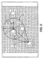
- Fig. 13 illustrates an embodiment of a user interface in which address carpet 12 is divided into hot zones having respective ranges of addresses corresponding to a graphic object which in turn corresponds to a system object or function.
- Computer 1712 utilizes a table that associates X, Y coordinates to one or more functions that are to be performed based on the X, Y coordinates.
- Activation could be signaled to computer 1712 by button 1714, such as a click or multiple click.
- activation could be signaled to computer 1712 by holding the image capture steady for a certain time.
- the precision of location selection is one glyph unit and the resolution of differentiated selection can be as fine as one glyph unit. Resolution can be extended to a fraction of a glyph unit provided the capture selection device can be referenced to the address carpet to within a fraction of a glyph interval. For example, a camera pixel is typically fraction of a glyph interval.
Abstract
Description
- This invention relates to the construction of multi-dimensional address spaces and, more particularly, to self-clocking and address carpet glyph instantiations of such address spaces and disambiguation techniques for address carpets.
- Glyphs are often encoded by respective elongated slash-like glyphs written on a two- dimensional, spatially periodic pattern of centers in accordance with a predetermined spatial formatting rule, with the individual glyphs being tilted to the left and right of vertical by approximately +45° and -45° for encoding logical "0's" and "1's", respectively. The mutual orthogonality of the glyph encodings for the two logical states of these single bit digital quanta enhances the discriminability of the code sufficiently to enable the embedded information to be recovered, even when the code pattern is written on a sufficiently fine grain pattern of center to cause the code pattern to have a generally uniform grayscale appearance.
- Prior proposals have dealt with the general subject of constructing address spaces in the image domain. For example, address spaces may be constructed by encoding cyclical pseudo-noise digital bit sequences (sometimes referred to as "PN sequences") and other types of maximal length-like digital bit sequences (i.e., sequences of length, L, in which every N-bit long subsequence is unique) in two dimensional spatially periodic self-clocking glyph code patterns. One of the unifying themes of these prior proposals is that they recommend constructing two dimensional address spaces by mapping at least two bit sequences of the foregoing type into such a code pattern so that these bit sequences are encoded to propagate in predetermined directions along respective non-parallel lines of glyphs.
- While it has been shown that the bit sequences need not be mapped into the code pattern in alignment with the principal axes thereof, it often is desirable to employ such mappings to reduce the computations that are required to determine the relative addresses of the glyphs in standard Cartesian coordinates (i.e., "x" and "y" parameters expressed in units of glyphs). Furthermore, it is known that the encodings of these bit sequences may completely or partially span the glyph code pattern, so it is to be understood that the addressing that is afforded by them is effective only within that portion of the glyph code pattern that projects onto both of the encodings. Moreover, the aforementioned bit sequences may be mapped into the glyphs on these non-parallel lines at unitary or fractional duty ratios, but it has been recognized that mappings preferably are spatially cyclical for applications in which it is desired to compute relative addresses for glyphs within the address space.
- Every bit in a maximal bit length sequence resides at a predetermined uniquely determinable logical position within the sequence. Accordingly, an ordered index of integers is commonly employed to distinguish those bits from each other on the basis of their respective ordinal logical positions within the sequence. These positionally dependent index numbers can, of course, be employed for selectively addressing the glyphs which encode the bits of such a sequence. However, addressing information in at least one additional dimension is required to uniquely identify the spatial locations of those glyphs or any other glyphs that are included within a two dimensional glyph code pattern. These unique identifiers of the individual glyphs are referred to as "absolute addresses" because they identify the unique locations at which the individual glyphs reside within the glyph code pattern.
- As is known, the spatial address (i.e., the absolute address) of almost any given glyph in an address space of the foregoing type is identifiable, at least to a first approximation, by a metric which specifies the offset distances (if any) between the nominal center of the given glyph and the non-parallel lines of glyphs that encode the respective maximal length bit sequences, where these offsets are measured parallel to the principal axes of the code pattern and are expressed in units of glyphs. In applications where the maximal length sequences are encoded by glyphs on orthogonal lines which align with the principal axes of a self-clocking glyph code pattern that is written on a regular rectangular lattice of centers, the above-described metric reduces to an x/y coordinate pair which identifies the spatial location of the given glyph with substantial precision in a standard Cartesian coordinate system. Unfortunately, however, the intersections of the lines on which these maximal bit length sequences are encoded tend to restrict the freedom of design choice if there are glyphs at any of these intersections.
- It has been shown that this unwanted limitation on the explicit spatial addressing of glyphs in self-clocking glyph code patterns can be avoided if the glyphs are written on a lattice of centers of predetermined width and/or height, so that there are a known or determinable fixed number of glyphs on every line of the code pattern along at least one of those dimensions. More particularly the solution that has been proposed for this special class of code patterns is to encode a maximal length bit sequence (or a combination of interleaved, relatively prime maximal length bit sequences) in the glyphs in a raster-like pattern which is selected to cause the logically ordered bits of the sequence to spatially propagate from side-to-side along a known dimension (say, the width) of the code pattern which more gradually propagating along the other (e.g., the height) of the code pattern in, say, top-to-bottom order. This raster encoding of the maximal length bit sequence effectively "folds" the bit sequence into the code pattern module a known or computable number of glyphs (i.e., the number of glyphs that the code pattern contains along its known dimension). Accordingly, the spatial address of any given glyph within the code pattern can be computed in x/y coordinate space from the sequence index number of the bit that is encoded by the glyph by dividing the sequence index number of the bit by the known glyph count/line modules.
- Unfortunately, this raster encoding style solution to the spatial addressing problem is not only limited to a constrained class of code patterns, but also tends to be computationally costly. The computational costs of this approach are elevated because the subsequence bit length, N, over which the maximal length bit sequence must be unique scales as a function of the square root of the address space that is being served. This scaling is an inherent consequence of the fact that the number of unique phases (or "bit index positions") of a maximal length bit sequence is given by N2 -1.
- Clearly, therefore, it would be desirable to have a more flexible technique for embedding logically ordered address information in some or all of the glyphs of self-clocking glyph code patterns for more computationally efficiently identifying the unique spatial locations of individual glyphs within such code patterns. Indeed, it would be desirable to parameterize such code patterns in N-dimensional space so that these address spaces, or fragments of them, can be used for hierarchically identifying two and three dimensional objects.
- Human interpretable textual, graphical or mixed textual and graphical representations of the files that are accessible via this user interface are spatially registered in superimposed or juxtaposed relationship with respective addresses in this address space. These spatial addresses, in turn, are logically registered in a lookup table or the like with computer recognizable descriptions of the respective file names and, if needed, paths to the directories for the named files.
- Fig. 1 illustrates a self-clocking glyph code pattern and a portion of its binary interpretation;
- Fig. 2 is a block diagram that shows an example of a user interface implemented using glyph address carpets;
- Fig. 3 is a block diagram of an image capture system that may be used to capture a user-selected portion of the glyph address carpet, and decode the glyphs in the captured portion;
- Fig. 4 shows an embodiment of a user interface implementing hot zones;
- Fig. 5 is a block diagram illustrating the selection process using
camera pen 1710; - Fig. 6 is a block diagram illustrating a second type of selection process that may be used to implement a graphical user interface consistent with the principles of the invention
- Fig. 7 illustrates an embodiment of the address codes encoded in the
glyph address carpet 1732; - Fig. 8 and Fig. 9 form a flow chart showing the disambiguation and address
decoding processes performed on the captured image area by
computer 1712; - Fig. 10 illustrates a binary data matrix 2310 formed from a glyph lattice
captured by
camera pen 1710; - Fig. 11 is a flowchart showing the process for performing correlation steps 2116 and 2118;
- Fig. 12 illustrates the analysis performed by
computer 1712 to determine the address encoded by the glyphs of the captured image; and - Fig. 13 illustrates how the
address carpet 1612 is divided into areas having respective ranges of addresses. -
- Turning now to the drawings, and at this point especially to Fig. 1, there is a more or less conventional self-clocking
glyph code pattern 21 which is composed of elongated slash-like marks or "glyphs" 22 and 23 that are written on a generally regular rectangular lattice of centers on asuitable recording medium 24. Suitably, theglyphs glyphs recording medium 24 to produce therectangular code pattern 21. The glyphs of these fine grain glyph code patterns are not easily resolved by the unaided human eye when the code patterns are viewed under standard lighting conditions and at normal reading distances, so thecode pattern 21 typically has a generally uniform gray scale appearance. Nevertheless, the glyph code is still capable of effectively communicating machine readable digital information. To carry out this function, theglyphs recording medium 24 to encode binary "1's" and "0's", respectively, as shown at 25. - In practice, the address space fragments 85-91 may be written directly on the objects 105-111, respectively, and/or on other substrates that are subsequently permanently or temporarily affixed to the objects. While a two dimensional address space can be employed for this application, more fully parameterized address spaces, such as the labeled address spaces AL1 ... ALn have the advantage of having a hierarchical organization which may be employed, as shown, to hierarchically organize object identifiers 85-91 by object type or any other desired classification.
- Fig. 2 is a block diagram that shows an example graphical user interface implemented using a glyph address carpet. The interface comprises two components: (1) sensory indicia and (2) a background which comprises a
glyph address carpet 1612. The address carpet may be visible or invisible. The sensory indicia in Fig. 2 are preferably visual indicia, and in particular graphic elements, such asicon 1610. Theglyph address carpet 1612 is used as the background wallpaper for the graphic elements. The glyph pattern that makes up the background is called an "address carpet" because the glyphs can be decoded to provide unique address information for each location. - The icons may, as shown in Fig. 2, be partially formed by glyphs that are part of the glyph address carpet. In the case of glyphtones (see, e.g., U.S. Patent No.5,315, 098 to Tow) and serpentones (see, e.g., U.S. Patent No. 5,706,099 to Curry), the indicia may be substantially composed of the glyphs themselves. Because the glyphs encode address information, a portion of the glyphs can be read optically and decoded to determine a unique address for a local position.
- The graphical user interface implemented using glyph address carpets can be implemented on any media capable of displaying the components of the interface. Thus, the interface could be implemented on hardcopy, such as paper, labels, physical objects, and photographic media; on dynamic displays such as a cathode ray tube (CRT) display or liquid crystal display (LCD); or on projected displays from fixed or dynamic media such as a slide projector, or television.
- Although the embodiment described herein utilizes glyphs, the glyphs can alternatively be replaced by any system, visible or invisible, that provides a data address code. Whereas the embodiment described herein utilizes visual indicia, the visual indicia can alternatively be replaced by any sensory indicia that could serve to guide a user or machine to select a location while the machine readable data address codes provide an address logical reference. The embodiment described herein utilizes a paper substrate, but the paper substrate can alternatively be replaced by any media in which the data address codes can be embedded and read by a machine.
- The sensory indicia may be embedded in the same media as the data address codes or may be embedded in other media. The sensory indicia can alternatively be projected onto glyphs, or glyphs can be projected onto sensory indicia.
- Fig. 3 is a block diagram of an image capture system that may be used to capture a user-selected portion of a graphical user interface, such as glyph address carpet 12, and decode the glyphs in the captured portion. In one embodiment,
computer system 1712 is a general purpose computer system, such as a conventional personal computer or laptop computer, that includesmain memory 1716, read only memory (ROM) 1718,storage device 1720,processor 1722, andcommunication interface 1724, all interconnected bybus 1726.Bus 1726 also connects to display 1730,cursor control 1714, andframe capture 1728. -
Image capture device 1710, which in this case is a camera pen, is connected to framecapture 1728 andmouse 1730.Camera pen 1710 transmits image information to framecapture 1728. In one embodiment,button 1714 ofcamera pen 1710 is wired tomouse 1730 so that when a user presses button 1714 a signal travels through the circuitry ofmouse 1728 tocursor control 1714. The signal causesprocessor 1722 to run a program that directsframe capture 1728 to capture the image fromcamera pen 1710. In another embodiment, both the image line and signal line fromcamera pen 1710 are input directly intoframe capture card 1728. The lines betweencamera pen 1710 andcomputer 1712 can be wired in any way that provides capture of the image fromcamera pen 1710. - The user makes a selection by placing
camera pen 1710 on or near visual indicia onglyph address carpet 1732, andpressing button 1714.Pressing button 1714 causescamera pen 1710 to capture the portion of the address carpet under the tip ofcamera pen 1710, and transmit the image tocomputer 1712, viaframe capture 1728, for analysis. The button or multiple buttons can be used for additional signaling, as in a double click, hold down. - Fig. 4 shows an embodiment of a user interface implementing hot zones. A hot zone is an area on or near the visual indica that defines selection locations that are equivalent to selecting the same visual indicia. In a preferred embodiment, the hot zone may encompass the visual indicia. For example, in Fig. 4, the icon David's DOC2 has a broken line area indicating a hot zone. If the user makes a selection within this hot zone, the icon "David's DOC2" will be selected. This allows the user to make a selection that is on or near the visual indicia. The selection is treated by the system as if the visual indicia was selected. The hot zone may be explicitly denoted by the visual indicia, including a visually distinct coloring in the address carpet, or may be implicit by appropriate proximity.
- Fig. 4 also illustrates a preferred embodiment for the glyph address carpet coding scheme. Each glyph is either a forward slash or a backward slash. The orientation and spacing of the rows and columns of glyphs is indicated by OGX and OGY, respectively. As denoted by the As and Bs in the drawing, an A code runs on every other line, and is interlaced with a B code. Along diagonals running down and to the right, every A value is preferably the same. Similarly, along diagonals running down and to the left, every B value is preferably the same.
- Fig. 5 is a block diagram illustrating the selection process using
camera pen 1710. Each icon has an effective selection area indicated by a broken linehot zone 1910. The tip ofcamera pen 1710 covers an area indicated by 1914. The orientation of the tip ofcamera pen 1710 is denoted by the YC axis and XC axis. To make a selection, the user places the tip ofcamera pen 1710 over the area to be selected. When the user pressesbutton 1714, the image withinarea 1914 is captured.Computer 1712 analyzes the captured image to determine the location of the center 1912 ofselection area 1914. After determining the location of center 1912, the location of center 1912 is used to look up a function corresponding to center 1912. - Fig. 6 is a block diagram illustrating a second type of selection process that may be used to implement a graphical user interface consistent with the principles of the invention. In this embodiment,
camera pen 1710 has a pointing device attached to the tip, thus making the image capture area of the pen offset from the location pointed at by the user. For example, in Fig. 6, a user selects the icon "David's DOC" by pointing to the icon, but thecamera pen 1710image capture area 2014, withcenter 2012, is offset from the icon. In this case,computer 1712 must determine the actual selection based on 1) theimage area 2014, and 2) the orientation of the selected area, and 3) the offset distance and direction from the image capture area fromcenter 2012. The offset calculation utilizes the glyph lattice parameters from the captured image decoding process described below. - Returning to Fig. 3, in one embodiment,
main memory 1716 is a random access memory (RAM) or a dynamic storage device that stores instructions executed byprocessor 1722.Main memory 1716 may also store information used in executing instructions.ROM 1718 is used for storing static information and instructions used byprocessor 1722.Storage device 1720, such as a magnetic or optical disk, also stores instructions and data used in the operation ofcomputer system 1712. -
Display 1730 may be a CRT or other type of display device.Cursor control 1714 controls cursor movement ondisplay 1730.Cursor control 1714 may be, for example, a mouse, a trackball or cursor direction keys. - The system shown in Fig. 3 can be used to implement the glyph address carpet capture and translation system described herein. The apparatus and methods described herein may be implemented by
computer system 1712 using hardware, software, or a combination of hardware and software. For example, the apparatus and methods described herein may be implemented as a program in any one or more ofmain memory 1716,ROM 1718, orstorage device 1720. In one embodiment,processor 1722 executes programs which analyze captured portions of a glyph address carpet to determine address information encoded in the glyphs. - Such programs may be read into
main memory 1716 from another computer-readable medium, such asstorage device 1720. Execution of sequences of instructions contained inmain memory 1716 causesprocessor 1722 to perform the process steps consistent with the present invention described herein. Execution of sequences of instructions contained inmain memory 1716 also causes processor to implement apparatus elements that perform the process steps. Hard-wired circuitry may be used in place of or in combination with software instructions to implement the invention. Thus, embodiments of the invention are not limited to any specific combination of hardware circuitry and software. - The term "computer-readable medium" as used herein refers to any medium that participates in providing instructions to
processor 1722 for execution. Such a medium may take many forms, including but not limited to, non-volatile memory media, volatile memory media, and transmission media. Non-volatile memory media includes, for example, optical or magnetic disks, such asstorage device 1720. Volatile memory media includes RAM, such asmain memory 1716. Transmission media includes coaxial cables, copper wire and fiber optics, including the wires that comprisebus 1726. Transmission media can also take the form of acoustic or light waves, such as those generated during radiowave and infrared data communications. - Common forms of computer-readable media include, for example, a floppy disk, a flexible disk, hard disk, magnetic tape, or any other magnetic storage medium, a CD-ROM, any other optical medium, punchcards, papertape, any other physical medium with patterns of holes, a RAM, a PROM, an EPROM, a FLASH-EPROM, any other memory chip or cartridge, a carrier wave as described hereinafter, or any other medium from which a computer can read and use.
- Various forms of computer readable media may be involved in carrying one or more sequences of instructions to
processor 1722 for execution. For example, the instructions may initially be carried on a magnetic disk or a remote computer. The remote computer can load the instructions into its dynamic memory and send the instructions over a telephone line using a modem. A modem local tocomputer system 1712 can receive the data on the telephone line and use an infrared transmitter to convert the data to an infrared signal. An infrared detector coupled to appropriate circuitry can receive the data carried in the infrared signal and place the data onbus 1726.Bus 1726 carries the data tomain memory 1716, from whichprocessor 1722 retrieves and executes the instructions. The instructions received bymain memory 1716 may optionally be stored onstorage device 1720 either before or after execution byprocessor 1722. -
Computer system 1712 also includes acommunication interface 1724 coupled tobus 1726.Communication interface 1724 provides two way communications to other systems. For example,communication interface 1724 may be an integrated services digital network (ISDN) card or a modem to provide a data communication connection to a corresponding type of telephone line. Communication may also be, for example, a local area network (LAN) card to provide communication to a LAN.Communication interface 1724 may also be a wireless card for implementing wireless communication betweencomputer system 1712 and wireless systems. In any such implementation,communication interface 1724 sends and receives electrical, electromagnetic or optical signals that carry data streams representing various types of information. - The link between
communication interface 1724 and external devices and systems typically provides data communication through one or more networks or other devices. For example, the link may provide a connection to a local network (not shown) to a host computer or to data equipment operated by an Internet Service Provider (ISP). An ISP provides data communication services through the world wide packet data communications network now commonly referred to as the "Internet". Local networks and the Internet both use electrical, electromagnetic or optical signals that carry digital data streams. The signals through the various networks and the signals between the networks andcommunication interface 1724, which carry the digital data to and fromcomputer system 1712, are exemplary forms of carrier waves transporting the information. -
Computer system 1712 can send messages and receive data, including program code, through the network(s) via the link betweencommunication interface 1724 and the external systems and devices. In the Internet, for example, a server might transmit a requested code for an application program through the Internet, an ISP, a local network, andcommunication interface 1724. - Program code received over the network may be executed by
processor 1722 as it is received, and/or stored in memory, such as instorage device 1720, for later execution. In this manner,computer system 1712 may obtain application code in the form of a carrier wave. - Fig. 7 illustrates an embodiment of the address codes encoded in the
glyph address carpet 1732. More particularly, Fig. 7 illustrates onesection 2110 of the glyph address carpet. The addresses are encoded by alternating rows of "A" address code sequences and "B" address code sequences. The position along each sequence in each row should be unambiguously determinable from a predetermined length subsequence. For example, an N-bit shift register maximal length code can be uniquely determined in position from an N-bit subsequence. Each address code sequence is a fifteen bit sequence, with the A sequence indexed running left to right, and the B sequence indexed running in a reverse direction, right to left. Each row of A code sequences is offset by two glyph positions relative to the previous and next row of A addresses. Similarly, each row of B code sequences is offset in the opposite direction by two positions. Thus, the encoding scheme has two key characteristics: parallel rows including two sets of one-dimensional unique address codes and relative offsets among members of the two sets so that the offset between each pair from the two sets is unique. This establishes two-dimensional unique address locations. -
Computer 1712 decodes address information encoded in the glyphs by analyzing the captured image area in two steps. Ideally, the user placescamera pen 1710 over a portion ofglyph address carpet 1732 and capture an image angularly aligned as shown in the pattern of bits shown in Fig. 7. In reality, however, the user variably orients thecamera pen 1710 over an area of interest, so the pattern could be oriented anywhere from 0° to 360°. Therefore, thecomputer 1712 must first determine the orientation of the image as part of decoding and interpreting the address information. - The orientation of the image is determined by analyzing the captured image. This process is called disambiguation. (See, e.g., U.S. Patent No. 5,521,372 to Hecht, et al.). After determining the proper orientation of the image,
computer 1712 decodes the address of the selected location in the address carpet. The disambiguation and address decoding processes performed bycomputer 1712 will now be described in greater detail. - Fig. 8 and Fig. 9 form a flow chart showing the disambiguation and address decoding processes performed by
computer 1712 on the captured image area.Computer 1712 begins the disambiguation process by image processing the captured portion of the address carpet to find a glyph seed. A glyph seed is a first-identified glyph having readable glyphs around it. Once a glyph seed has been found, the glyph lattice can be determined by processing neighbors of the glyph seed. (See Appendices A and B). The glyphs are then decoded as 1's or 0's, which are filled into a binary data matrix having rows and columns corresponding to the glyph lattice rows. The orientation may still be ambiguous with respect to 90° and 180° rotations. - Fig. 10 illustrates a binary data matrix (BDM) 2310 formed from a glyph lattice captured by
camera pen 1710. The BDM has locations corresponding to the glyph lattice. Thus the size of the BDM corresponds closely to the size of the glyph lattice. - Each location of the glyph lattice is analyzed to determine which value should be placed in the corresponding location of the BDM. Initially, the BDM is filled with a value, for example , which indicates that no attempt has been made to read the glyph. Once the glyph corresponding to a particular location has been analyzed, the is replaced by a value indicating the result of the glyph analysis.
- In Fig. 10, a B indicates a border location; an X indicates that no interpretable glyph was found at the corresponding location of the glyph lattice; an E indicates a glyph at the edge of the captured image portion; a 0 indicates a back slash glyph; and a 1 indicates a forward slash glyph. The area of the matrix corresponding the captured image is filled with 0's and 1's, the edge is bounded by Es, and the Xs correspond to locations that have no readable glyphs. In practice, however, although the BDM will generally have a similar pattern, the values will often not be as evenly distributed. For example, a glyph location within the captured image area might result in an X if the glyph has been obliterated. Several values have been drawn with circles and squares around them to illustrate the two separate code sequences that are staggered in opposite directions.
- When a user makes a selection, the user might orient the camera pen in virtually any direction on the user interface. The captured image could be oriented at any angle. Thus, even though
step 2210 allowscomputer 1712 to derive a BDM of 0's and 1's from the captured image, it is uncertain whether the BDM is oriented at 0° (i.e., correctly oriented), 90°, 180°, or 270° relative to the original code pattern in the glyph address carpet from which the image was captured. Until the orientation of the captured image is determined, it is not possible to derive the correct address code from the BDM. The orientation could be provided by auxiliary information such as physical system constraints. However, the orientation can be uniquely determined directly from the address codes. - After converting the glyphs to 0's and 1's, a reference glyph location is selected (step 2211). This location may be chosen in a variety of ways, but is typically a location which represents the selection. For example, the reference glyph location could be at the center of the BDM.
- After the image has been converted to a BDM, it is processed by computer 1712 (step 2212). The original BDM developed from the captured image is referred to as BDM1.
Computer 1712 makes a copy of BDM1 and rotates the copy clockwise 90° to form a second binary data matrix, BDM2 (step 2214). By rotating BDM1 by 90°, the rows of BDM1 become the columns of BDM2, and the columns of BDM1 become the rows of BDM2. Additionally, all bit values in BDM2 are flipped from 0 to 1, and 1 to 0, because a 45° slash glyph rotated 90° appears as the opposite state of the non-rotated glyph. -
Computer 1712 then performs a correlation separately on the odd and even rows of BDM1 (step 2216) to determine whether code in the rows are staggered forward or backward. The correlation is also performed for the odd and even rows of BDM2 (step 2218). The correlation is performed over all the rows of each BDM, and results in correlation value C1 for BDM1 and correlation value C2 for BDM2. - Fig. 11 is a flowchart showing an embodiment of
correlation steps -
Computer 1712 first inputs the BDM (step 2410), and then copies every other row to a temporary matrix (step 2412). Identical processes are then performed for diagonals to the right and to the left.Steps step 2416. Thus, after the process has correlated each adjacent row, the correlation value C_RIGHT indicates the strength of the correlation along the diagonals to the right. - The steps on the right of Fig. 11 are similar to
steps - The process steps of Fig. 11 are performed for the odd and even rows of BDM1 and the odd and even rows of BDM2. From this information, the correlation value C1 for BDM1 is set to C1EVEN + C1ODD (as determined by Fig. 11 for the rows of BDM1), and the correlation value C2 for BDM2 is set to C2EVEN + C2ODD (as determined by Fig. 11 for the rows of BDM1).
- Fig. 12 illustrates why the correlations determine which way the codes in every other row are shifting. For example, as indicated by the circled A1s along the diagonals running to the right, the codes along the diagonal starting at A1 in the first position of the second row should have the same value in every other row along the diagonal, except for erasures and errors. Similarly, as indicated by the boxed B1s, the codes along the diagonal starting at B1 in the upper right corner should have the same value in every other row along the diagonal, except for erasures or errors. This is true for each value along the diagonal in the odd rows running respectively from B2, B3, ... in the top row. Thus, the strong correlations along the diagonals running down and to the left on the odd rows, and the strong correlations along the diagonals running down and to the right on the even rows indicate that the codes in the even rows are shifting to the right, and the codes in the odd rows are shifting to the left.
- For each BDM, therefore, four correlation values are developed: 1) odd rows, right to left, 2) odd rows, left to right, 3) even rows, right to left and 4) even rows, left to right. From these correlation values, the strongest correlation value for the even rows, and strongest correlation value for the odd rows is chosen, and these become CEVEN and CODD for that BDM (
steps 2216 and 2218). CEVEN and CODD are then added to form a final C correlation value for that BDM. As discussed above with respect to step 2220, the BDM with the strongest correlation value is the BDM that is oriented at either 0° or 180° because of the relative orientation of the codes in the odd and even rows. Thus, two aspects of the chosen BDM are now established: which direction every other line of codes is staggered, and that the BDM is oriented horizontally, at either 0° or 180°. Another correlation process,step 2230 is performed to determine which direction the code in each line runs (as opposed to which way the code is staggered). - The codes in the odd lines are staggered in one direction, and the codes in the even lines are staggered in the other. This staggering property of the code, in conjunction with knowing the respective codes that run in the odd lines and even lines, allows determination of the proper 0° orientation of the BDM.
- Returning to Fig. 8, if C1 is greater than C2 (step 2220), then BDM1 is selected for further processing. C1 being greater than C2 indicates that the one-dimensional codes of BDM1 are most strongly correlated and are, therefore, oriented at either 0° or 180° (step 2222). If C2 is greater than C1, then BDM2 is selected for further processing, because the higher correlation indicates that BDM2 is oriented at either 0° or 180° (step 2224). Thus, the correct BDM has been found. Before determining the address location of the captured image, however,
computer 1712 must first determine whether the selected BDM is at 0° (i.e., oriented correctly), or rotated by 180°. - Fig. 9 is a flowchart showing the steps of how
computer 1712 determines the address of the captured area of the glyph carpet. Preferably, bit positions along a diagonal in the BDM, when the BDM is oriented at 0°, have the same value at every other row. The image capture process and interference from the visual indicia, however, may result in errors and erasures in the BDM data. To reduce the impact of these errors and erasures,computer 1712 performs a majority vote along each diagonal of the odd rows in the direction the odd rows are staggered, and repeats the majority vote process for even rows along the each diagonal in the direction the even rows are staggered (step 2225). This results in a first code sequence for the odd rows and a second code sequence for the even rows. To the extent the majority vote correctly determines each bit position, the first and second code sequences should match a subsequence of the original pseudo noise address sequence respectively corresponding to the odd or even set of rows. -
Computer 1712 then retrieves the original pseudo noise address code (Get Code 1) for rows staggered forward (step 2226), and retrieves the original pseudo noise address code for (Get Code 2) for rows staggered backward (step 2228). Using the original pseudo noise address code for each code set A and B, and the code from the majority voting,computer 1712 performs four cross correlations (step 2230) to establishes the best match of the glyph sequence with the PN sequence location for the odd and even rows. - More particularly, two adjacent rows of the BDM closest to the reference element chosen in
step 2211 are correlated with the respective complete PN sequences that created the original address carpet. The PN sequences could be identical. A forward and backward correlation is performed for each row. The four correlations develop four pairs of peak correlation and position values: - 1) P1, V1, respectively representing the peak correlation value and
corresponding position for
Code 1 correlated backwards with the complete PN sequence; - 2) Q1, U1, respectively representing the peak correlation value and
corresponding position for
Code 2 correlated forwards with the complete PN sequence; - 3) P2, V2, respectively representing the peak correlation value and
corresponding position for
Code 1 correlated forwards with the complete PN sequence; and - 4) Q2, U2, respectively representing the peak correlation value and
corresponding position for
Code 2 correlated backwards with the complete PN sequence. -
- The Ui and Vi, position values, where i = 1 or 2, corresponding to the peak magnitudes are used to determine the X and Y values corresponding to the reference element chosen in
step 2211. Thus, if (P1 + Q1) > (P2 + Q2) (step 2232), then Ul and V1 are used to calculate the X, Y position of the reference glyph location chosen in step 2211 (step 2236). If (P1 + Q1) <= (P2 + Q2) (step 2232), then U2 and V2 are used to calculate the X, Y position of the reference glyph location chosen in step 2211 (step 2234). The address information is determined in accordance with the following equations: - The calculated X, Y position is then returned (step 2238). Note that diagonals correspond to constant values of U and V, respectively, while rows and columns correspond to constant X and Y. Note also that U and V could be used directly as address parameters.
- Thus, an X, Y value associated with the reference point chosen in
step 2211 has been determined. Using this information,computer 1712 associates the X, Y coordinates with a logical reference, or a combination of a logical reference and a control signal (e.g., a button click), with a particular operation to be performed. For example, the X, Y coordinates could be used as an index into a table of operations performable bycomputer 1712 or other device under direction ofcomputer 1712. The X, Y coordinates could be associated with a file open command that opens a file associated with an icon located near the X, Y coordinates in the address space. Virtually any operation that can be performed bycomputer 1712 could be associated with a particular X, Y coordinate, or range of X, Y coordinates. - Fig. 13 illustrates an embodiment of a user interface in which address carpet 12 is divided into hot zones having respective ranges of addresses corresponding to a graphic object which in turn corresponds to a system object or function.
Computer 1712 uses the X,Y address determined from the image capture to determine which area of address carpet 12 was selected by the user. For example, if the address is X=1052 and Y=32, which is in the upper left area of address carpet 12, then the user has selected CloseWin.avi.Computer 1712 utilizes a table that associates X, Y coordinates to one or more functions that are to be performed based on the X, Y coordinates. For example, in the above example, X=1052 and Y=32 would be associated with the one or more functions to be performed when a user selects CloseWin.avi. Activation could be signaled tocomputer 1712 bybutton 1714, such as a click or multiple click. Alternatively, activation could be signaled tocomputer 1712 by holding the image capture steady for a certain time. The precision of location selection is one glyph unit and the resolution of differentiated selection can be as fine as one glyph unit. Resolution can be extended to a fraction of a glyph unit provided the capture selection device can be referenced to the address carpet to within a fraction of a glyph interval. For example, a camera pixel is typically fraction of a glyph interval. - Methods, systems and articles of manufacture consistent with the present invention therefore facilitate implementation of a graphical user interface using glyph address carpets. The foregoing description of an implementation of the invention has been presented for purposes of illustration and description. It is not exhaustive and does not limit the invention to the precise form disclosed. Modifications and variations are possible in light of the above teachings or may be acquired from practicing of the invention.
Claims (2)
- Apparatus for implementing a user interface, comprising:sensory indicia embodied in a media (1732);a two-dimensional embedded data address code (2110);a reader for reading a portion of the two-dimensional address code (1710); anda translator (1722) for translating the portion into a discrete pointer associated with the sensory indicia.
- A method for implementing a user interface using sensory indicia embedded in a media and a two-dimensional embedded data address code, comprising:reading a portion of the two-dimensional address code (2210); andtranslating the portion into a discrete pointer (2238).
Applications Claiming Priority (2)
| Application Number | Priority Date | Filing Date | Title |
|---|---|---|---|
| US144251 | 1988-01-15 | ||
| US09/144,251 US6327395B1 (en) | 1996-12-20 | 1998-08-31 | Glyph address carpet methods and apparatus for providing location information in a multidimensional address space |
Publications (3)
| Publication Number | Publication Date |
|---|---|
| EP0984390A2 true EP0984390A2 (en) | 2000-03-08 |
| EP0984390A3 EP0984390A3 (en) | 2001-01-10 |
| EP0984390B1 EP0984390B1 (en) | 2009-02-25 |
Family
ID=22507759
Family Applications (1)
| Application Number | Title | Priority Date | Filing Date |
|---|---|---|---|
| EP99306875A Expired - Lifetime EP0984390B1 (en) | 1998-08-31 | 1999-08-27 | Apparatus for providing location information in a multidimensional address space |
Country Status (4)
| Country | Link |
|---|---|
| US (1) | US6327395B1 (en) |
| EP (1) | EP0984390B1 (en) |
| JP (1) | JP4353591B2 (en) |
| DE (1) | DE69940454D1 (en) |
Cited By (12)
| Publication number | Priority date | Publication date | Assignee | Title |
|---|---|---|---|---|
| WO2001048678A1 (en) * | 1999-12-23 | 2001-07-05 | Anoto Ab | Distributed information management |
| WO2001095091A1 (en) * | 2000-06-07 | 2001-12-13 | Anoto Ab | Method and device for encrypting a message |
| WO2002015118A1 (en) * | 2000-08-16 | 2002-02-21 | Gavitec Ag | Method for automatically identifying a directed structure |
| WO2002021794A2 (en) * | 2000-09-08 | 2002-03-14 | Findthedot,Inc. | A method and system of connecting printed media to electronic information as a response to a request |
| EP1217579A2 (en) * | 2000-12-19 | 2002-06-26 | Xerox Corporation | Method and apparatus for implementing occlusion glyph code tilings |
| US6667695B2 (en) | 2001-06-25 | 2003-12-23 | Anoto Ab | Position code |
| US6958747B2 (en) | 2000-08-30 | 2005-10-25 | Anoto Ab | Method for making a product |
| US7175095B2 (en) | 2001-09-13 | 2007-02-13 | Anoto Ab | Coding pattern |
| US7457413B2 (en) | 2000-06-07 | 2008-11-25 | Anoto Ab | Method and device for encrypting a message |
| US7999798B2 (en) | 2001-10-29 | 2011-08-16 | Anoto Ab | Method and device for decoding a position-coding pattern |
| US8162220B2 (en) | 1999-10-01 | 2012-04-24 | Anoto Ab | Product provided with a coding pattern and apparatus and method for reading the pattern |
| WO2021119185A1 (en) * | 2019-12-10 | 2021-06-17 | Pony Ai Inc. | Dynamic memory address encoding |
Families Citing this family (55)
| Publication number | Priority date | Publication date | Assignee | Title |
|---|---|---|---|---|
| AUPQ131399A0 (en) * | 1999-06-30 | 1999-07-22 | Silverbrook Research Pty Ltd | A method and apparatus (NPAGE02) |
| US6650761B1 (en) | 1999-05-19 | 2003-11-18 | Digimarc Corporation | Watermarked business cards and methods |
| US6330976B1 (en) | 1998-04-01 | 2001-12-18 | Xerox Corporation | Marking medium area with encoded identifier for producing action through network |
| SE516522C2 (en) * | 1999-05-28 | 2002-01-22 | Anoto Ab | Position determining product for digitization of drawings or handwritten information, obtains displacement between symbol strings along symbol rows when symbol strings are repeated on symbol rows |
| US7176896B1 (en) * | 1999-08-30 | 2007-02-13 | Anoto Ab | Position code bearing notepad employing activation icons |
| US6935562B2 (en) | 1999-12-06 | 2005-08-30 | Xerox Corporation | Operations on images having glyph carpets |
| US6880755B2 (en) | 1999-12-06 | 2005-04-19 | Xerox Coporation | Method and apparatus for display of spatially registered information using embedded data |
| US6678425B1 (en) | 1999-12-06 | 2004-01-13 | Xerox Corporation | Method and apparatus for decoding angular orientation of lattice codes |
| EP2056233B1 (en) * | 1999-12-23 | 2011-10-19 | Anoto AB | Information management system |
| US20030061188A1 (en) * | 1999-12-23 | 2003-03-27 | Linus Wiebe | General information management system |
| US8418052B2 (en) | 2000-03-21 | 2013-04-09 | Anoto Aktiebolag (Anoto Ab) | Processing of documents |
| US6572025B1 (en) * | 2000-05-10 | 2003-06-03 | Japan Gain The Summit Co., Ltd. | Information code product, manufacturing device and method for manufacturing the same, information code reading device, authentication system, authentication terminal, authentication server, and authentication method |
| US6601772B1 (en) * | 2000-07-14 | 2003-08-05 | Intellidot Corporation | Compact matrix code and one-touch device and method for code reading |
| US7333947B2 (en) * | 2000-11-13 | 2008-02-19 | Anoto Ab | Network-based system |
| US8341194B2 (en) * | 2001-04-02 | 2012-12-25 | Accenture Global Services Limited | Matrix-based user interface and system for creating the same |
| US20040139100A1 (en) * | 2001-04-02 | 2004-07-15 | Gottsman Edward J. | Context-based display technique |
| US7185824B2 (en) * | 2001-04-13 | 2007-03-06 | The Code Corporation | System and method for associating pre-printed machine-readable graphical codes with electronically-accessible data |
| US6915281B2 (en) * | 2002-06-30 | 2005-07-05 | Pitney Bowes Inc. | Systems and methods using a digital pen for funds accounting devices and postage meters |
| US7417773B2 (en) * | 2002-09-30 | 2008-08-26 | Pitney Bowes Inc. | Method and system for creating and sending a facsimile using a digital pen |
| US7082444B2 (en) * | 2002-09-30 | 2006-07-25 | Pitney Bowes Inc. | Method and system for identifying a form version |
| US7167586B2 (en) * | 2002-09-30 | 2007-01-23 | Pitney Bowes Inc. | Method and system for remote form completion |
| US7343042B2 (en) * | 2002-09-30 | 2008-03-11 | Pitney Bowes Inc. | Method and system for identifying a paper form using a digital pen |
| US7133563B2 (en) | 2002-10-31 | 2006-11-07 | Microsoft Corporation | Passive embedded interaction code |
| US7121469B2 (en) * | 2002-11-26 | 2006-10-17 | International Business Machines Corporation | System and method for selective processing of digital images |
| US7648678B2 (en) | 2002-12-20 | 2010-01-19 | Dako Denmark A/S | Method and system for pretreatment of tissue slides |
| US7840492B2 (en) * | 2002-12-30 | 2010-11-23 | Pitney Bowes Inc. | Personal funds metering system and method |
| US7110576B2 (en) * | 2002-12-30 | 2006-09-19 | Pitney Bowes Inc. | System and method for authenticating a mailpiece sender |
| JP3635374B1 (en) | 2003-11-14 | 2005-04-06 | 有限会社Sires | Digital information carrier |
| US7111230B2 (en) * | 2003-12-22 | 2006-09-19 | Pitney Bowes Inc. | System and method for annotating documents |
| US7581171B2 (en) * | 2004-01-06 | 2009-08-25 | Microsoft Corporation | Positionally encoded document image analysis and labeling |
| US7263224B2 (en) | 2004-01-16 | 2007-08-28 | Microsoft Corporation | Strokes localization by m-array decoding and fast image matching |
| JP4606089B2 (en) * | 2004-01-16 | 2011-01-05 | パナソニック株式会社 | Article position detection method and RFID tag position calibration system |
| JP4041993B2 (en) * | 2004-06-01 | 2008-02-06 | ソニー株式会社 | Display device, light receiving device, communication system, and communication method |
| SE0401647D0 (en) | 2004-06-28 | 2004-06-28 | Anoto Ab | Coding and decoding of data |
| JP4487690B2 (en) * | 2004-08-27 | 2010-06-23 | ソニー株式会社 | Display device, communication system and method |
| US7607076B2 (en) | 2005-02-18 | 2009-10-20 | Microsoft Corporation | Embedded interaction code document |
| US7826074B1 (en) | 2005-02-25 | 2010-11-02 | Microsoft Corporation | Fast embedded interaction code printing with custom postscript commands |
| JP2006254299A (en) * | 2005-03-14 | 2006-09-21 | Fuji Xerox Co Ltd | Image generating device or image reader, method, program, and storage medium |
| US7421439B2 (en) | 2005-04-22 | 2008-09-02 | Microsoft Corporation | Global metadata embedding and decoding |
| US7400777B2 (en) | 2005-05-25 | 2008-07-15 | Microsoft Corporation | Preprocessing for information pattern analysis |
| US7729539B2 (en) | 2005-05-31 | 2010-06-01 | Microsoft Corporation | Fast error-correcting of embedded interaction codes |
| US7580576B2 (en) * | 2005-06-02 | 2009-08-25 | Microsoft Corporation | Stroke localization and binding to electronic document |
| EP1913526A4 (en) | 2005-06-17 | 2014-05-07 | Anoto Ab | Method and system for combining a position and information code |
| US7817816B2 (en) | 2005-08-17 | 2010-10-19 | Microsoft Corporation | Embedded interaction code enabled surface type identification |
| US7621442B2 (en) | 2005-09-19 | 2009-11-24 | Silverbrook Research Pty Ltd | Printing a subscription using a mobile device |
| US7469829B2 (en) * | 2005-09-19 | 2008-12-30 | Silverbrook Research Pty Ltd | Printing video information using a mobile device |
| US7756526B2 (en) | 2005-09-19 | 2010-07-13 | Silverbrook Research Pty Ltd | Retrieving a web page via a coded surface |
| US7855805B2 (en) | 2005-09-19 | 2010-12-21 | Silverbrook Research Pty Ltd | Printing a competition entry form using a mobile device |
| US7445160B2 (en) | 2006-06-14 | 2008-11-04 | Hewlett-Packard Development Company, L.P. | Position location using error correction |
| US7913920B2 (en) | 2006-12-20 | 2011-03-29 | Palo Alto Research Center Incorporated | Document processing devices, systems and methods thereof |
| US20090040563A1 (en) * | 2007-08-07 | 2009-02-12 | Xerox Corporation | Printing job control system and method |
| JP5557419B2 (en) * | 2007-10-17 | 2014-07-23 | スパンション エルエルシー | Semiconductor device |
| US7991153B1 (en) | 2008-08-26 | 2011-08-02 | Nanoglyph, LLC | Glyph encryption system and related methods |
| US8593697B2 (en) * | 2010-01-11 | 2013-11-26 | Hewlett-Packard Development Company, L.P. | Document processing |
| US8651389B2 (en) * | 2011-02-02 | 2014-02-18 | Infosys Limited | System and method for identifying and tracking shopping carts |
Citations (4)
| Publication number | Priority date | Publication date | Assignee | Title |
|---|---|---|---|---|
| US3891829A (en) * | 1973-08-29 | 1975-06-24 | Monarch Marking Systems Inc | Coded records, method of making same and method and an apparatus for reading coded records |
| US4260979A (en) * | 1979-12-31 | 1981-04-07 | International Business Machines Corporation | Apparatus for sensing non-coded images |
| EP0853271A1 (en) * | 1997-01-14 | 1998-07-15 | Seiko Instruments Information Devices Inc. | Method of starting function of an information processing unit and co-ordinate reading system |
| US5937110A (en) * | 1996-12-20 | 1999-08-10 | Xerox Corporation | Parallel propagating embedded binary sequences for characterizing objects in N-dimensional address space |
Family Cites Families (14)
| Publication number | Priority date | Publication date | Assignee | Title |
|---|---|---|---|---|
| US5168147A (en) | 1990-07-31 | 1992-12-01 | Xerox Corporation | Binary image processing for decoding self-clocking glyph shape codes |
| US5574804A (en) | 1990-12-21 | 1996-11-12 | Olschafskie; Francis | Hand-held scanner |
| US5301243A (en) | 1990-12-21 | 1994-04-05 | Francis Olschafskie | Hand-held character-oriented scanner with external view area |
| US5978552A (en) * | 1991-11-28 | 1999-11-02 | Sony Corporation | Ruled line generating apparatus and sheet for use therein |
| US5739814A (en) * | 1992-09-28 | 1998-04-14 | Sega Enterprises | Information storage system and book device for providing information in response to the user specification |
| US5453605A (en) * | 1993-12-22 | 1995-09-26 | Xerox Corporation | Global addressability for self-clocking glyph codes |
| US5449895A (en) | 1993-12-22 | 1995-09-12 | Xerox Corporation | Explicit synchronization for self-clocking glyph codes |
| FR2724237B1 (en) | 1994-09-06 | 1997-01-31 | Cherloc | OPTICAL DEVICE FOR READING PENCIL |
| US5572010A (en) | 1995-01-03 | 1996-11-05 | Xerox Corporation | Distributed type labeling for embedded data blocks |
| US5576532A (en) | 1995-01-03 | 1996-11-19 | Xerox Corporation | Interleaved and interlaced sync codes and address codes for self-clocking glyph codes |
| US5600121A (en) | 1995-03-20 | 1997-02-04 | Symbol Technologies, Inc. | Optical reader with independent triggering and graphical user interface |
| US5565669A (en) | 1995-09-06 | 1996-10-15 | Intermec Corporation | Orientation independent method for robust computing of X-dimensions in code one symbols |
| US5742041A (en) | 1996-05-29 | 1998-04-21 | Intermec Corporation | Method and apparatus for locating and decoding machine-readable symbols, including data matrix symbols |
| US6102505A (en) | 1997-12-18 | 2000-08-15 | Eastman Kodak Company | Recording audio and electronic images |
-
1998
- 1998-08-31 US US09/144,251 patent/US6327395B1/en not_active Expired - Lifetime
-
1999
- 1999-08-27 DE DE69940454T patent/DE69940454D1/en not_active Expired - Lifetime
- 1999-08-27 EP EP99306875A patent/EP0984390B1/en not_active Expired - Lifetime
- 1999-08-31 JP JP24653399A patent/JP4353591B2/en not_active Expired - Fee Related
Patent Citations (4)
| Publication number | Priority date | Publication date | Assignee | Title |
|---|---|---|---|---|
| US3891829A (en) * | 1973-08-29 | 1975-06-24 | Monarch Marking Systems Inc | Coded records, method of making same and method and an apparatus for reading coded records |
| US4260979A (en) * | 1979-12-31 | 1981-04-07 | International Business Machines Corporation | Apparatus for sensing non-coded images |
| US5937110A (en) * | 1996-12-20 | 1999-08-10 | Xerox Corporation | Parallel propagating embedded binary sequences for characterizing objects in N-dimensional address space |
| EP0853271A1 (en) * | 1997-01-14 | 1998-07-15 | Seiko Instruments Information Devices Inc. | Method of starting function of an information processing unit and co-ordinate reading system |
Cited By (18)
| Publication number | Priority date | Publication date | Assignee | Title |
|---|---|---|---|---|
| US8534566B2 (en) | 1999-10-01 | 2013-09-17 | Anoto Ab | Product provided with a coding pattern and apparatus and method for reading the pattern |
| US8162220B2 (en) | 1999-10-01 | 2012-04-24 | Anoto Ab | Product provided with a coding pattern and apparatus and method for reading the pattern |
| WO2001048678A1 (en) * | 1999-12-23 | 2001-07-05 | Anoto Ab | Distributed information management |
| US7457413B2 (en) | 2000-06-07 | 2008-11-25 | Anoto Ab | Method and device for encrypting a message |
| WO2001095091A1 (en) * | 2000-06-07 | 2001-12-13 | Anoto Ab | Method and device for encrypting a message |
| WO2002015118A1 (en) * | 2000-08-16 | 2002-02-21 | Gavitec Ag | Method for automatically identifying a directed structure |
| US7701446B2 (en) | 2000-08-30 | 2010-04-20 | Anoto Aktiebolag (Anoto Ab) | Method for making a product |
| US6958747B2 (en) | 2000-08-30 | 2005-10-25 | Anoto Ab | Method for making a product |
| WO2002021794A3 (en) * | 2000-09-08 | 2002-05-16 | Findthedot Inc | A method and system of connecting printed media to electronic information as a response to a request |
| WO2002021794A2 (en) * | 2000-09-08 | 2002-03-14 | Findthedot,Inc. | A method and system of connecting printed media to electronic information as a response to a request |
| US7079667B2 (en) | 2000-12-19 | 2006-07-18 | Xerox Corporation | Method and apparatus for implementing occlusion glyph code tilings |
| EP1217579A3 (en) * | 2000-12-19 | 2003-05-28 | Xerox Corporation | Method and apparatus for implementing occlusion glyph code tilings |
| EP1217579A2 (en) * | 2000-12-19 | 2002-06-26 | Xerox Corporation | Method and apparatus for implementing occlusion glyph code tilings |
| US6667695B2 (en) | 2001-06-25 | 2003-12-23 | Anoto Ab | Position code |
| US7175095B2 (en) | 2001-09-13 | 2007-02-13 | Anoto Ab | Coding pattern |
| US7999798B2 (en) | 2001-10-29 | 2011-08-16 | Anoto Ab | Method and device for decoding a position-coding pattern |
| WO2021119185A1 (en) * | 2019-12-10 | 2021-06-17 | Pony Ai Inc. | Dynamic memory address encoding |
| US11200167B2 (en) | 2019-12-10 | 2021-12-14 | Pony Ai Inc. | Dynamic memory address encoding |
Also Published As
| Publication number | Publication date |
|---|---|
| DE69940454D1 (en) | 2009-04-09 |
| EP0984390A3 (en) | 2001-01-10 |
| JP2000099257A (en) | 2000-04-07 |
| EP0984390B1 (en) | 2009-02-25 |
| JP4353591B2 (en) | 2009-10-28 |
| US6327395B1 (en) | 2001-12-04 |
Similar Documents
| Publication | Publication Date | Title |
|---|---|---|
| EP0984390B1 (en) | Apparatus for providing location information in a multidimensional address space | |
| US6208771B1 (en) | Methods and apparatus for robust decoding of glyph address carpets | |
| US6594406B1 (en) | Multi-level selection methods and apparatus using context identification for embedded data graphical user interfaces | |
| US6678425B1 (en) | Method and apparatus for decoding angular orientation of lattice codes | |
| US6935562B2 (en) | Operations on images having glyph carpets | |
| US6880755B2 (en) | Method and apparatus for display of spatially registered information using embedded data | |
| EP1553485B1 (en) | Positionally encoded document image analysis and labeling | |
| US7386191B2 (en) | Decoding and error correction in 2-D arrays | |
| US7580576B2 (en) | Stroke localization and binding to electronic document | |
| US20060242562A1 (en) | Embedded method for embedded interaction code array | |
| US20020021284A1 (en) | System and method for determining positional information | |
| JP2000099257A5 (en) | ||
| CA2491579C (en) | Enhanced approach of m-array decoding and error correction | |
| EP1915724A1 (en) | Embedded interaction code enabled surface type identification | |
| US5862271A (en) | Parallel propagating embedded binary sequences for characterizing and parameterizing two dimensional image domain code patterns in N-dimensional address space | |
| EP1553486B1 (en) | Global localization by fast image matching | |
| CN103098075B (en) | Using the absolute position of light pen and the point code pattern of other information, printing point coding method, read point coding method | |
| EP1557793B1 (en) | Method and apparatus for registering, displaying and decoding of information for spatial registration | |
| US5870510A (en) | Parallel propagating embedded binary sequences for parameterizing two dimensional image domain code patterns in N-dimensional address space |
Legal Events
| Date | Code | Title | Description |
|---|---|---|---|
| PUAI | Public reference made under article 153(3) epc to a published international application that has entered the european phase |
Free format text: ORIGINAL CODE: 0009012 |
|
| AK | Designated contracting states |
Kind code of ref document: A2 Designated state(s): DE FR GB |
|
| AX | Request for extension of the european patent |
Free format text: AL;LT;LV;MK;RO;SI |
|
| PUAL | Search report despatched |
Free format text: ORIGINAL CODE: 0009013 |
|
| AK | Designated contracting states |
Kind code of ref document: A3 Designated state(s): AT BE CH CY DE DK ES FI FR GB GR IE IT LI LU MC NL PT SE |
|
| AX | Request for extension of the european patent |
Free format text: AL;LT;LV;MK;RO;SI |
|
| RIC1 | Information provided on ipc code assigned before grant |
Free format text: 7G 06K 19/06 A, 7G 06K 11/08 B |
|
| 17P | Request for examination filed |
Effective date: 20010710 |
|
| AKX | Designation fees paid |
Free format text: DE FR GB |
|
| 17Q | First examination report despatched |
Effective date: 20061130 |
|
| GRAP | Despatch of communication of intention to grant a patent |
Free format text: ORIGINAL CODE: EPIDOSNIGR1 |
|
| RIC1 | Information provided on ipc code assigned before grant |
Ipc: G06K 19/06 20060101AFI20080908BHEP |
|
| GRAS | Grant fee paid |
Free format text: ORIGINAL CODE: EPIDOSNIGR3 |
|
| GRAA | (expected) grant |
Free format text: ORIGINAL CODE: 0009210 |
|
| AK | Designated contracting states |
Kind code of ref document: B1 Designated state(s): DE FR GB |
|
| REG | Reference to a national code |
Ref country code: GB Ref legal event code: FG4D |
|
| REF | Corresponds to: |
Ref document number: 69940454 Country of ref document: DE Date of ref document: 20090409 Kind code of ref document: P |
|
| PLBE | No opposition filed within time limit |
Free format text: ORIGINAL CODE: 0009261 |
|
| STAA | Information on the status of an ep patent application or granted ep patent |
Free format text: STATUS: NO OPPOSITION FILED WITHIN TIME LIMIT |
|
| 26N | No opposition filed |
Effective date: 20091126 |
|
| REG | Reference to a national code |
Ref country code: FR Ref legal event code: PLFP Year of fee payment: 18 |
|
| PGFP | Annual fee paid to national office [announced via postgrant information from national office to epo] |
Ref country code: DE Payment date: 20160721 Year of fee payment: 18 Ref country code: GB Payment date: 20160726 Year of fee payment: 18 |
|
| PGFP | Annual fee paid to national office [announced via postgrant information from national office to epo] |
Ref country code: FR Payment date: 20160720 Year of fee payment: 18 |
|
| REG | Reference to a national code |
Ref country code: DE Ref legal event code: R119 Ref document number: 69940454 Country of ref document: DE |
|
| GBPC | Gb: european patent ceased through non-payment of renewal fee |
Effective date: 20170827 |
|
| REG | Reference to a national code |
Ref country code: FR Ref legal event code: ST Effective date: 20180430 |
|
| PG25 | Lapsed in a contracting state [announced via postgrant information from national office to epo] |
Ref country code: GB Free format text: LAPSE BECAUSE OF NON-PAYMENT OF DUE FEES Effective date: 20170827 Ref country code: DE Free format text: LAPSE BECAUSE OF NON-PAYMENT OF DUE FEES Effective date: 20180301 |
|
| PG25 | Lapsed in a contracting state [announced via postgrant information from national office to epo] |
Ref country code: FR Free format text: LAPSE BECAUSE OF NON-PAYMENT OF DUE FEES Effective date: 20170831 |