EP0984540A2 - Rechargeable battery pack with identification circuit, real time clock and authentication capability - Google Patents
Rechargeable battery pack with identification circuit, real time clock and authentication capability Download PDFInfo
- Publication number
- EP0984540A2 EP0984540A2 EP99119971A EP99119971A EP0984540A2 EP 0984540 A2 EP0984540 A2 EP 0984540A2 EP 99119971 A EP99119971 A EP 99119971A EP 99119971 A EP99119971 A EP 99119971A EP 0984540 A2 EP0984540 A2 EP 0984540A2
- Authority
- EP
- European Patent Office
- Prior art keywords
- battery pack
- circuit
- battery
- recharging
- charging
- Prior art date
- Legal status (The legal status is an assumption and is not a legal conclusion. Google has not performed a legal analysis and makes no representation as to the accuracy of the status listed.)
- Granted
Links
Images


Classifications
-
- H—ELECTRICITY
- H02—GENERATION; CONVERSION OR DISTRIBUTION OF ELECTRIC POWER
- H02J—CIRCUIT ARRANGEMENTS OR SYSTEMS FOR SUPPLYING OR DISTRIBUTING ELECTRIC POWER; SYSTEMS FOR STORING ELECTRIC ENERGY
- H02J7/00—Circuit arrangements for charging or depolarising batteries or for supplying loads from batteries
- H02J7/02—Circuit arrangements for charging or depolarising batteries or for supplying loads from batteries for charging batteries from ac mains by converters
- H02J7/04—Regulation of charging current or voltage
-
- H—ELECTRICITY
- H02—GENERATION; CONVERSION OR DISTRIBUTION OF ELECTRIC POWER
- H02J—CIRCUIT ARRANGEMENTS OR SYSTEMS FOR SUPPLYING OR DISTRIBUTING ELECTRIC POWER; SYSTEMS FOR STORING ELECTRIC ENERGY
- H02J7/00—Circuit arrangements for charging or depolarising batteries or for supplying loads from batteries
- H02J7/00032—Circuit arrangements for charging or depolarising batteries or for supplying loads from batteries characterised by data exchange
- H02J7/00038—Circuit arrangements for charging or depolarising batteries or for supplying loads from batteries characterised by data exchange using passive battery identification means, e.g. resistors or capacitors
-
- H—ELECTRICITY
- H02—GENERATION; CONVERSION OR DISTRIBUTION OF ELECTRIC POWER
- H02J—CIRCUIT ARRANGEMENTS OR SYSTEMS FOR SUPPLYING OR DISTRIBUTING ELECTRIC POWER; SYSTEMS FOR STORING ELECTRIC ENERGY
- H02J7/00—Circuit arrangements for charging or depolarising batteries or for supplying loads from batteries
- H02J7/00032—Circuit arrangements for charging or depolarising batteries or for supplying loads from batteries characterised by data exchange
- H02J7/00036—Charger exchanging data with battery
-
- H—ELECTRICITY
- H02—GENERATION; CONVERSION OR DISTRIBUTION OF ELECTRIC POWER
- H02J—CIRCUIT ARRANGEMENTS OR SYSTEMS FOR SUPPLYING OR DISTRIBUTING ELECTRIC POWER; SYSTEMS FOR STORING ELECTRIC ENERGY
- H02J7/00—Circuit arrangements for charging or depolarising batteries or for supplying loads from batteries
- H02J7/00047—Circuit arrangements for charging or depolarising batteries or for supplying loads from batteries with provisions for charging different types of batteries
-
- Y—GENERAL TAGGING OF NEW TECHNOLOGICAL DEVELOPMENTS; GENERAL TAGGING OF CROSS-SECTIONAL TECHNOLOGIES SPANNING OVER SEVERAL SECTIONS OF THE IPC; TECHNICAL SUBJECTS COVERED BY FORMER USPC CROSS-REFERENCE ART COLLECTIONS [XRACs] AND DIGESTS
- Y10—TECHNICAL SUBJECTS COVERED BY FORMER USPC
- Y10S—TECHNICAL SUBJECTS COVERED BY FORMER USPC CROSS-REFERENCE ART COLLECTIONS [XRACs] AND DIGESTS
- Y10S320/00—Electricity: battery or capacitor charging or discharging
- Y10S320/18—Indicator or display
- Y10S320/21—State of charge of battery
Definitions
- the present invention is directed to a battery apparatus, and more particularly a battery apparatus having means for identifying individual batteries, a real-time clock, and means for authenticating batteries.
- Rechargeable batteries have some great advantages when compared with regular, disposable batteries. For example, rechargeable batteries have a lower lifetime cost for most applications.
- rechargeable batteries also have some disadvantages. For example, every time a rechargeable battery is used or recharged, a substantial transport of material takes place in the battery. In practice, it is impossible to design a battery so that the distribution of material involved will be unchanged over time, though such a design would be desirable. An increasing number of charging cycles will result in an uneven distribution of material inside the battery with a rising risk of malfunction, for example, an internal short-circuit of the battery, as a result thereof. It is of great importance to minimize the risk of malfunction of a battery, because every malfunction means a potential risk for people and material in vicinity of the battery.
- U.S. Patent No. 5,136,620 to Eaves discloses an electronic counting device for counting the charge cycles accumulated on a battery.
- the counting device consists of a display by which a counted value is output to the user. The user must know what the count means in terms of the battery life; there is no mechanism by which the application circuit or recharging device to which the battery is connected receives this information.
- U.S. Patent No. 4,593,409 to Miller discloses a warning and protection circuit arrangement suitable for use in conjunction with a two-way portable transceiver having a removable battery pack/antenna which includes a battery enclosure containing an antenna structure.
- a circuit is enclosed inside the battery enclosure for providing information indicative of certain predetermined parameters of the antenna or the battery. This information may be used by the transceiver to provide the user with an alert in the event an inappropriate battery pack/antenna is being used.
- this requires the provision of a separate circuit thus increasing the size and cost of the battery pack.
- a cellular telephone including a battery time monitor having a real time clock is disclosed in U.S. Patent No. 5,248,929 to Burke.
- This patent discloses use of the battery time monitor which provides a user with a visual feedback as to the amount of time remaining for operation of the cellular telephone so that the user may determine how long the next call can last before the battery is discharged.
- this requires a separate circuit within the cellular telephone to monitor the battery.
- the clock is provided in the cellular telephone circuit, if the battery becomes totally discharged, the real time clock may lose its ability to keep time accurately.
- the present invention overcomes the disadvantages noted above.
- the present invention relates to a battery pack which allows instant identification of the battery pack and the use of such identification for purposes for controlling the recharging of the battery.
- every battery pack is provided with a signature which is easy to produce and easy to recognize with a high degree of probability to make it possible for the charger and/or the battery powered apparatus to recognize a single individual battery.
- a real time clock is also provided within the battery pack.
- a battery identification system is provided which allows easy identification of counterfeit battery packs.
- an apparatus for identifying an individual battery pack, comprising at least one resistor having a particular resistance value, and a supervising unit for reading the particular resistance value of the at least one resistor to determine the individual identity of the battery pack.
- an apparatus for controlling recharging of an individual battery pack comprising means for identifying a particular battery pack, and supervising means for selectively allowing and preventing recharging of the individual battery pack responsive to the means for identifying.
- an apparatus for providing date and time information to an application circuit which uses a battery pack, the apparatus comprising a real-time clock provided in the battery pack, and means for providing real-time clock information from the real-time clock to the application circuit to which the battery pack is connected.
- an apparatus for controlling an operational state of an application circuit, the apparatus comprising means for verifying the authenticity of a battery pack which has been connected to an application circuit, the means for verifying comprising means for storing a predetermined mathematical formula provided in the battery pack and in the application circuit, means for generating a random number, means for calculating a first result of the mathematical formula in the battery pack using the random number, means for calculating a second result of the mathematical formula in the application circuit using the random number, and means for comparing the first result to the second result and outputting a verification signal, the apparatus further comprising means for placing the application circuit in an non-operational state responsive to the means for verifying when the verification signal indicates that the first result does not equal the second result.
- the supervising unit is provided in the charging apparatus (for example, a separate charger, not shown) or in the battery-powered equipment (for example, a cellular mobile phone, pager, or video cam corder, not shown).
- the supervising unit has the ability to identify individual batteries. Upon recognizing a particular battery individual, the charging apparatus or battery powered equipment will only accept recharging for a limited number of cycles. The number of available cycles is based on tests made by the manufacturer or an independent laboratory. A safety factor may also be incorporated in the number for each battery type, which safety factor can be chosen from the test data. The setting of the available cycles for the different battery types is believed to be within the skill of the ordinary artisan in possession of the instant disclosure.
- FIG. 1 The exemplary implementation of such a supervising circuit 12 is shown in Figure 1.
- N resistors are installed, N having a minimum value of one.
- the resistors are provided in the range of zero to ⁇ ohms.
- the resistors R1 and R2 are connected between connectors C 1 , C 2 and C 3 that can be reached on the surface of the battery unit 10.
- One or more of the connectors may be connected to more than one resistor or to any other part of the battery, for example, the "+" pole. In this way, the value or values of the resistor or resistors can be used as a fingerprint of the battery to recognize a particular individual battery, and can be used as a key to permit recharging of the particular battery pack.
- N a number of factors may be considered. These include what is practical and the needed probability that the owner of the battery powered apparatus does not get two or more batteries with each set of resistors.
- a preferred range for the value for each resistor is between 0 to 100 k ⁇ and an open circuit.
- supervising circuit 12 includes an analog to digital (A/D) converter 14 connected to the resistors and the terminal units or connectors C 1 , C 2 and C 3 of the battery unit.
- the A/D convener 14 output provides the digital equivalent of the resistance value to the central processing unit (CPU) 16.
- the CPU 16 is connected to a memory unit 18 for storing the recharging information associated with the particular individuals.
- the memory unit 18 may be a non-volatile memory or a volatile memory which is supplied with power either by the battery pack or from a separate external power source.
- the memory unit 18 is a volatile memory which requires a relatively small amount of current such that the battery pack itself can supply power to the memory unit regardless of the charging condition of the battery pack.
- Reference resistance value R ref and a reference current I ref are used to allow the supervising unit 12 to read the values of R 1 and R 2 to identify the battery individual.
- a current I ref is run through R ref , R 1 , and R 2 and the voltage potential across the resistors is measured by the A/D converter 14.
- the potential generated by R ref is entered into the A/D converter 14 for the purpose of allowing the supervising unit 12 to read the values of R 1 and R 2 regardless of the degree of energization of the battery.
- An alarm means 20 is connected to the CPU 16 to allow the user to be informed that the battery pack has reached the end of its useful life.
- the alarm means 20 may consist of an audio alarm, a display, an LED, a vibrating alarm, or any other suitable device.
- FIG. 2 illustrates a flow chart for implementing the present invention which program is executed by the CPU 16.
- the battery is inserted into the recharging apparatus or the battery powered equipment (step 201).
- the resistance values of R 1 and R 2 are measured using I ref (step 203) which produces a measurable potential difference (voltage drop) across R 1 of the series connected resistor pair R 1 , R 2 , and resistance R ref which acts as a voltage divider circuit.
- step 205 it is determined whether the individual identified by the resistors R 1 and R 2 is an earlier identified or known battery. If not, at step 206 the battery is registered and its identity is stored in the memory unit 18 and the memory 18 is incremented by one to count the number of charging cycles. Alternatively, the memory 18 can be used to track the total charging time experienced by the particular battery pack. If the individual battery is recognized at step 205, step 207 determines whether any more cycles are available to that individual battery. If so, one is added to the cycle count in the memory unit 18 associated with that individual battery (step 209). If no more cycles are available, step 208 sends an alarm or takes other action to inform the user that the life time of the individual battery is over.
- the memory 18 stores the charging status of the identified battery pack, either by keeping track of the number of charging cycles the battery pack has experienced, or the total charging time. Means are provided to signal the charging status to the memory. As noted above, the charging status can be monitored by counting the number of charging cycles experienced by the battery pack or by tracking the total charging time experienced by the battery pack.
- the signalling means 22 can be provided either in the supervising circuit of the battery pack, as shown in Figure 1, or in the battery charging circuit (not shown). If the signalling means is provided in the battery charging circuit, the signal may be transmitted either by a partially separate bus or on the ordinary discharging wires. The signalling means 22 signals a change in the charging status every time the battery pack is connected to the battery charging circuit.
- the signalling means 22 signals a change in the charging status as a function of the total charge which is given to the battery pack at every charge period.
- the total charging time times the current input into the battery is monitored each time the battery pack is charged up, and that total is sent to the memory 18, to be summed with the previous stored charging time.
- the total charging time reaches a predetermined maximum, further recharging is prohibited or the user is warned as described herein.
- a message is provided to the user in a display (not shown) that the lifetime of the battery is nearing an end and it should be disposed of due to safety reasons. This message may be given by light signal, on a display, by sound (buzzer or voice) or any other method that is normally used for messages.
- Another alternative is to refuse to accept the particular battery individual anymore and provide the user with the message to that effect as in the first alternative.
- a third alternative is that a circuit element in the battery pack may be destroyed so that the individual battery will be useless for future use. If desired, a message can be provided to the user to this effect.
- a transistor may be employed to create a short circuit between the "+" and "-" terminals of the battery which blows a fuse inside the battery pack. This embodiment is described in more detail below.
- FIG. 3A and 3B Another embodiment of the invention is shown in Figures 3A and 3B.
- a resistive ink may be printed in an individual pattern on the surface of the battery.
- Contact springs 30 may be provided on the outside of the battery pack 10 which touch the surface of the battery pack at specified points. A resistance between the springs will be used to identify and control the recharging of individual batteries according to the software program shown in Figure 2.
- a bar code or resistive bar code may be used to identify battery pack individuals.
- Another embodiment of the present invention is to have individual signatures, for example, a set of magnets, disposed close to the surface of the battery pack.
- the reading of the magnetic signature can be implemented using any magneto-sensitive arrangement such as, for example, Hall elements or an array of such elements which feeds the supervising circuit with the information required.
- "smart cards” that is, the family of small, more or less intelligent cards with a semiconductor chip, in a contact pattern, for example, the "SIM” card used in Ericsson cellular telephones, can be used to identify individual battery packs.
- at least two connectors, of which one can be the power connector, will be connected to a chip inside the battery pack.
- the chip will in the most simple version, be only a memory, preferably a non-volatile serial ROM or a RAM with a serial number inside.
- FIG. 4 Another embodiment of the present invention is shown in Figure 4 in which the battery pack 10' contains a circuit that will prohibit further charging of the battery pack when a predetermined number of charging cycles is approaching or has been reached or a predetermined total charging time is approaching or has been reached, or any other situation occurs such that no further charging is recommended due to safety or other reasons.
- such circuit consists of a charge detection circuit 43 for detecting the charging of the battery pack 10', a central processing unit (CPU) 47, a memory 44, and a back up battery or capacitor 46.
- the charge detection circuit 43 may be implemented as a Schmitt trigger or an analog to digital converter.
- the memory 44 can be either a volatile or a non-volatile memory.
- the back up battery/capacitor 46 may be omitted if the memory 44 is non-volatile memory.
- a switch 40 is connected between the charge detection circuit 43 and the battery 10'.
- the switch 40 for example, may be provided as an FET transistor 42 and a diode 41.
- the diode 41 can be omitted in an alternative embodiment.
- the circuitry will be able to point out these battery packs.
- the identification number provided by the resistors could be displayed to the user on the application display, or on a separate battery pack display.
- battery packs which have been stressed by heat may need to be replaced after a lower number of recharging cycles than battery packs that have been used under more suitable conditions.
- a temperature sensor may be provided in the battery pack to detect whether such a stress has been experienced and can so indicate to the CPU. The CPU can then consider this stress to control the number of available recharging cycles permissible for the particular individual battery.
- FIG. 5 Another embodiment of the present invention as shown in Figure 5 in which a real time clock is provided within the battery pack.
- the circuitry can be used to communicate the real time data to the application, that is, for example, a cellular telephone. This can be accomplished by having an extra pin on the battery pack and the application. If the battery pack is of a rechargeable type, it is possible that the battery may become totally discharged. This may cause the real time circuit to lose the real time information. In such a case, it will be possible to enter date and time information from the application.
- the cellular telephone or other applications includes a microprocessor 50 and a display 52 as well as a voltage regulator 54 providing a constant voltage source to the circuit elements.
- a crystal element provides a 32 kHz signal to the real time clock.
- the battery pack shown in Fig. 5 includes a real time clock 45, an alarm 58, a 32 kHz crystal, and an arithmetic and logic unit (ALU) 59.
- a microprocessor may be used instead of the ALU 59.
- the display 52 displays the time and data obtained from the real time clock 45 from the data line connected to the microprocessor 50 in the application circuit.
- the data line is connected to a first pin provided in the battery pack which is connected to a second pin provided in the application circuit (represented in Figure 5 by a °).
- the built-in-alarm 58 provided in the battery pack for example, a vibrator or a buzzer, may be activated at a predetermined time based on the real time clock information.
- the predetermined time may be set by a control panel 48 on the battery pack ( Figure 4) or the control panel 56 normally used in the battery charger or in the application ( Figure 5).
- the real time clock can also be used to activate or shut down the battery powered application in a predetermined manner.
- the predetermination of the shut down time can be done by a control panel on the battery pack or the control panel normally used with the application equipment.
- the microprocessor 50 in the application places the application circuit in a non-operational mode, that is, it shuts off the application, when the real time clock reaches the predetermined time.
- the real time clock may be used to control the recharging of the battery pack.
- the real time clock may provide the basis for counting the total charging time experienced by the battery pack as described above.
- An advantage achieved by the present invention occurs by adding the clock to the battery pack itself since the clock will always have the power to keep the tine correctly during charging and the back up battery or capacitor can be eliminated.
- the microprocessor in the application equipment can communicate with the clock circuit to inquire as to the current time, set an alarm and set the time. The connections would also enable the microprocessor to be woken up by the clock circuit in the event of an alarm.
- the memory and the CPU of the battery pack such as that shown in Figure 4 is used in conjunction with the memory and CPU in the application circuit (not shown) to make it possible for the battery powered application or the battery charger to distinguish a correct battery from a battery that is manufactured by somebody else.
- the memory unit 44 contains mathematical formula that is also known to the application circuit and stored in the memory thereof (not shown).
- the application When the application is powered up, it retrieves the stored mathematical formula from the application memory (step 60). At the same time, the battery pack 10' retrieves the stored mathematical formula from the battery memory unit 44. A random number is generated by the application equipment (step 62). This random number is used as the input to the mathematical formula stored in the battery pack as well as that stored in the application. The first result of the mathematical formula is calculated in the battery pack using the random number generated in step 62 (step 64). The second result of the mathematical formula is calculated in the application using the random number generated in step 62 (step 66). The result of both calculations are communicated to the application where they are compared at step 68.
- step 70 If the first result is not equal to the second result, this indicates that the battery pack is a counterfeit battery pack and the application is placed in an non-operational state (step 70). If the application is placed in the non-operational state, the reason therefor may be communicated to the user by a display or alarm. If the first result equals the second result, the application is permitted to operate at step 72. If the application is placed in the non-operational state, this reason therefore may be communicated to the user by a display or alarm.
- a modular-two addition to a number hidden in the battery pack may serve to determine whether the battery pack is counterfeit.
- the charger or application sends a number in serial form to the battery pack.
- the CPU in the battery pack adds a number with module-two addition and returns the results to the supervising unit, the battery charger or the application.
- the supervising unit checks whether or not the hidden number from the battery pack is a member of the accepted group of numbers.
Abstract
Description
- The present invention is directed to a battery apparatus, and more particularly a battery apparatus having means for identifying individual batteries, a real-time clock, and means for authenticating batteries.
- Rechargeable batteries have some great advantages when compared with regular, disposable batteries. For example, rechargeable batteries have a lower lifetime cost for most applications.
- However, rechargeable batteries also have some disadvantages. For example, every time a rechargeable battery is used or recharged, a substantial transport of material takes place in the battery. In practice, it is impossible to design a battery so that the distribution of material involved will be unchanged over time, though such a design would be desirable. An increasing number of charging cycles will result in an uneven distribution of material inside the battery with a rising risk of malfunction, for example, an internal short-circuit of the battery, as a result thereof. It is of great importance to minimize the risk of malfunction of a battery, because every malfunction means a potential risk for people and material in vicinity of the battery.
- Today, battery manufacturers try to minimize the risks by providing over-pressure vents, explosion-safe encapsulation, etc. One way to minimize the risk of malfunction is to allow only a limited number or charging cycles during the lifetime of a rechargeable battery. In other words, the life-time of the battery may be defined by a number of charging cycles or a maximum charging time. When using this type of battery, it would be of value if environmental factors as well, for example, heat, could be used for the calculation of the acceptable number of charging cycles.
- U.S. Patent No. 5,136,620 to Eaves discloses an electronic counting device for counting the charge cycles accumulated on a battery. However, the counting device consists of a display by which a counted value is output to the user. The user must know what the count means in terms of the battery life; there is no mechanism by which the application circuit or recharging device to which the battery is connected receives this information.
- Other prior art combinations of batteries and charging circuits have had either a simple way to identify a battery as a member of a certain class or family (U.S. Patent No. 5,184,059 to Patino et al. and U.S. Patent No. 5,200,686 to Lee), or a complex arrangement inside the battery pack to secure that this battery pack individual will be treated the best way (U.S. Patent No. 4,553,081 to Koenck, U.S. Patent No. 5,057,083 to Sokira, U.S. Patent No. 4,965,738 to Bauer et al., and U.S. Patent No. 4,289,836 to Lemelson). However, these devices do not provide a signature for every battery pack which is easy to produce and easy to recognize with a high degree of probability, to make it possible for the charger and/or the battery-powered apparatus to recognize a single individual battery.
- Another problem found in existing rechargeable batteries results from the marketing of batteries made by unauthorized manufacturers. In particular, manufacturers of portable equipment which is supplied with power by rechargeable batteries want to supply the market with their own batteries. This is a result of both commercial and technical considerations. If a customer buys a battery from an unauthorized manufacturer, there may be a safety risk because the batteries are not compatible with the original battery charger.
- For example, U.S. Patent No. 4,593,409 to Miller discloses a warning and protection circuit arrangement suitable for use in conjunction with a two-way portable transceiver having a removable battery pack/antenna which includes a battery enclosure containing an antenna structure. A circuit is enclosed inside the battery enclosure for providing information indicative of certain predetermined parameters of the antenna or the battery. This information may be used by the transceiver to provide the user with an alert in the event an inappropriate battery pack/antenna is being used. However, this requires the provision of a separate circuit thus increasing the size and cost of the battery pack.
- A cellular telephone including a battery time monitor having a real time clock is disclosed in U.S. Patent No. 5,248,929 to Burke. This patent discloses use of the battery time monitor which provides a user with a visual feedback as to the amount of time remaining for operation of the cellular telephone so that the user may determine how long the next call can last before the battery is discharged. However, this requires a separate circuit within the cellular telephone to monitor the battery. Additionally, because the clock is provided in the cellular telephone circuit, if the battery becomes totally discharged, the real time clock may lose its ability to keep time accurately.
- The present invention overcomes the disadvantages noted above.
- The present invention relates to a battery pack which allows instant identification of the battery pack and the use of such identification for purposes for controlling the recharging of the battery. According to the present invention, every battery pack is provided with a signature which is easy to produce and easy to recognize with a high degree of probability to make it possible for the charger and/or the battery powered apparatus to recognize a single individual battery. A real time clock is also provided within the battery pack. Further, according to the present invention, a battery identification system is provided which allows easy identification of counterfeit battery packs.
- According to one embodiment of the present invention, an apparatus is provided for identifying an individual battery pack, comprising at least one resistor having a particular resistance value, and a supervising unit for reading the particular resistance value of the at least one resistor to determine the individual identity of the battery pack.
- According to one embodiment of the present invention, an apparatus is provided for controlling recharging of an individual battery pack comprising means for identifying a particular battery pack, and supervising means for selectively allowing and preventing recharging of the individual battery pack responsive to the means for identifying.
- According to one embodiment of the present invention, an apparatus is provided for providing date and time information to an application circuit which uses a battery pack, the apparatus comprising a real-time clock provided in the battery pack, and means for providing real-time clock information from the real-time clock to the application circuit to which the battery pack is connected.
- According to one embodiment of the present invention, an apparatus is provided for controlling an operational state of an application circuit, the apparatus comprising means for verifying the authenticity of a battery pack which has been connected to an application circuit, the means for verifying comprising means for storing a predetermined mathematical formula provided in the battery pack and in the application circuit, means for generating a random number, means for calculating a first result of the mathematical formula in the battery pack using the random number, means for calculating a second result of the mathematical formula in the application circuit using the random number, and means for comparing the first result to the second result and outputting a verification signal, the apparatus further comprising means for placing the application circuit in an non-operational state responsive to the means for verifying when the verification signal indicates that the first result does not equal the second result.
- Still other objects, features and attendant advantages of the present invention will become apparent to those skilled in the art from a reading of the following detailed description of the embodiments constructed in accordance therewith, taken in conjunction with the accompanying drawings.
- The invention of the present application will now be described in more detail with reference to the preferred embodiments of the device, given only by way of example, and with reference to the accompanying drawings, in which:
- Figure 1 illustrates an exemplary configuration for the battery pack according to a preferred embodiment of the present invention;
- Figure 2 illustrates a flow chart for implementing an embodiment of the present invention;
- Figure 3A illustrates an implementation of another embodiment of the present invention;
- Figure 3B is a cross section along the line 3-3 of Figure 3A;
- Figure 4 is another embodiment of the present invention;
- Figure 5 is an illustration of another embodiment of the present invention; and
- Figure 6 is a flow chart for implementing a preferred embodiment of the present invention.
-
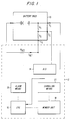
- According to the present invention, only a limited number of charging cycles are permitted during the lifetime of a rechargeable battery. According to a preferred embodiment of the present invention, as shown in Figure 1, the supervising unit is provided in the charging apparatus (for example, a separate charger, not shown) or in the battery-powered equipment (for example, a cellular mobile phone, pager, or video cam corder, not shown). The supervising unit has the ability to identify individual batteries. Upon recognizing a particular battery individual, the charging apparatus or battery powered equipment will only accept recharging for a limited number of cycles. The number of available cycles is based on tests made by the manufacturer or an independent laboratory. A safety factor may also be incorporated in the number for each battery type, which safety factor can be chosen from the test data. The setting of the available cycles for the different battery types is believed to be within the skill of the ordinary artisan in possession of the instant disclosure.
- The exemplary implementation of such a
supervising circuit 12 is shown in Figure 1. In everybattery pack 10, N resistors are installed, N having a minimum value of one. The resistors are provided in the range of zero to ∞ ohms. As shown in Figure 1, the resistors R1 and R2 are connected between connectors C1, C2 and C3 that can be reached on the surface of thebattery unit 10. One or more of the connectors may be connected to more than one resistor or to any other part of the battery, for example, the "+" pole. In this way, the value or values of the resistor or resistors can be used as a fingerprint of the battery to recognize a particular individual battery, and can be used as a key to permit recharging of the particular battery pack. - For example, by selecting two resistors in the E-12 series, 3,000 combinations having different resistance values are available. This would provide reasonable individuality to enable the charging circuit to identify individual batteries with little conflict.
- In choosing the number of resistors N, a number of factors may be considered. These include what is practical and the needed probability that the owner of the battery powered apparatus does not get two or more batteries with each set of resistors. A preferred range for the value for each resistor is between 0 to 100 kΩ and an open circuit.
- According to a preferred embodiment, supervising
circuit 12 includes an analog to digital (A/D)converter 14 connected to the resistors and the terminal units or connectors C1, C2 and C3 of the battery unit. The A/D convener 14 output provides the digital equivalent of the resistance value to the central processing unit (CPU) 16. TheCPU 16 is connected to amemory unit 18 for storing the recharging information associated with the particular individuals. Thememory unit 18 may be a non-volatile memory or a volatile memory which is supplied with power either by the battery pack or from a separate external power source. According to one embodiment, thememory unit 18 is a volatile memory which requires a relatively small amount of current such that the battery pack itself can supply power to the memory unit regardless of the charging condition of the battery pack. - Reference resistance value Rref and a reference current Iref are used to allow the supervising
unit 12 to read the values of R1 and R2 to identify the battery individual. In particular, a current Iref is run through Rref, R1, and R2 and the voltage potential across the resistors is measured by the A/D converter 14. The potential generated by Rref is entered into the A/D converter 14 for the purpose of allowing the supervisingunit 12 to read the values of R1 and R2 regardless of the degree of energization of the battery. - An alarm means 20 is connected to the
CPU 16 to allow the user to be informed that the battery pack has reached the end of its useful life. The alarm means 20 may consist of an audio alarm, a display, an LED, a vibrating alarm, or any other suitable device. - Figure 2 illustrates a flow chart for implementing the present invention which program is executed by the
CPU 16. In particular, the battery is inserted into the recharging apparatus or the battery powered equipment (step 201). The resistance values of R1 and R2 are measured using Iref (step 203) which produces a measurable potential difference (voltage drop) across R1 of the series connected resistor pair R1, R2, and resistance Rref which acts as a voltage divider circuit. - At
step 205, it is determined whether the individual identified by the resistors R1 and R2 is an earlier identified or known battery. If not, atstep 206 the battery is registered and its identity is stored in thememory unit 18 and thememory 18 is incremented by one to count the number of charging cycles. Alternatively, thememory 18 can be used to track the total charging time experienced by the particular battery pack. If the individual battery is recognized atstep 205,step 207 determines whether any more cycles are available to that individual battery. If so, one is added to the cycle count in thememory unit 18 associated with that individual battery (step 209). If no more cycles are available,step 208 sends an alarm or takes other action to inform the user that the life time of the individual battery is over. - Referring to Figure 1, the
memory 18 stores the charging status of the identified battery pack, either by keeping track of the number of charging cycles the battery pack has experienced, or the total charging time. Means are provided to signal the charging status to the memory. As noted above, the charging status can be monitored by counting the number of charging cycles experienced by the battery pack or by tracking the total charging time experienced by the battery pack. The signalling means 22 can be provided either in the supervising circuit of the battery pack, as shown in Figure 1, or in the battery charging circuit (not shown). If the signalling means is provided in the battery charging circuit, the signal may be transmitted either by a partially separate bus or on the ordinary discharging wires. The signalling means 22 signals a change in the charging status every time the battery pack is connected to the battery charging circuit. Alternatively, the signalling means 22 signals a change in the charging status as a function of the total charge which is given to the battery pack at every charge period. In particular, the total charging time times the current input into the battery is monitored each time the battery pack is charged up, and that total is sent to thememory 18, to be summed with the previous stored charging time. When the total charging time reaches a predetermined maximum, further recharging is prohibited or the user is warned as described herein. - According to preferred embodiments, there are a number of alternatives to be taken at
step 208 to indicate to the user that the useful life time of the battery is limited to a few remaining cycles or that the useful life of the battery pack is over. That is, when the battery has been discharged the predetermined number of cycles allowable for that battery pack or the total charging time for the battery pack has been is approaching or has been exceeded, one of a number of things may happen. One alternative is that a message is provided to the user in a display (not shown) that the lifetime of the battery is nearing an end and it should be disposed of due to safety reasons. This message may be given by light signal, on a display, by sound (buzzer or voice) or any other method that is normally used for messages. Another alternative is to refuse to accept the particular battery individual anymore and provide the user with the message to that effect as in the first alternative. A third alternative is that a circuit element in the battery pack may be destroyed so that the individual battery will be useless for future use. If desired, a message can be provided to the user to this effect. - According to the third alternative, a transistor may be employed to create a short circuit between the "+" and "-" terminals of the battery which blows a fuse inside the battery pack. This embodiment is described in more detail below.
- Another embodiment of the invention is shown in Figures 3A and 3B. In particular, rather than using resistors from the first embodiment, a resistive ink may be printed in an individual pattern on the surface of the battery. Contact springs 30 may be provided on the outside of the
battery pack 10 which touch the surface of the battery pack at specified points. A resistance between the springs will be used to identify and control the recharging of individual batteries according to the software program shown in Figure 2. According to another embodiment, a bar code or resistive bar code may be used to identify battery pack individuals. - Another embodiment of the present invention, not shown in the drawings, is to have individual signatures, for example, a set of magnets, disposed close to the surface of the battery pack. The reading of the magnetic signature can be implemented using any magneto-sensitive arrangement such as, for example, Hall elements or an array of such elements which feeds the supervising circuit with the information required.
- According to another embodiment of the present invention, "smart cards", that is, the family of small, more or less intelligent cards with a semiconductor chip, in a contact pattern, for example, the "SIM" card used in Ericsson cellular telephones, can be used to identify individual battery packs. In this embodiment, at least two connectors, of which one can be the power connector, will be connected to a chip inside the battery pack. The chip will in the most simple version, be only a memory, preferably a non-volatile serial ROM or a RAM with a serial number inside.
- Another embodiment of the present invention is shown in Figure 4 in which the battery pack 10' contains a circuit that will prohibit further charging of the battery pack when a predetermined number of charging cycles is approaching or has been reached or a predetermined total charging time is approaching or has been reached, or any other situation occurs such that no further charging is recommended due to safety or other reasons. As shown in Figure 4, such circuit consists of a
charge detection circuit 43 for detecting the charging of the battery pack 10', a central processing unit (CPU) 47, amemory 44, and a back up battery orcapacitor 46. Thecharge detection circuit 43 may be implemented as a Schmitt trigger or an analog to digital converter. Thememory 44 can be either a volatile or a non-volatile memory. The back up battery/capacitor 46 may be omitted if thememory 44 is non-volatile memory. Aswitch 40 is connected between thecharge detection circuit 43 and the battery 10'. Theswitch 40, for example, may be provided as anFET transistor 42 and adiode 41. Thediode 41 can be omitted in an alternative embodiment. When theCPU 47 determines that the individual battery has reached its charging capacity, it sends a signal to close theswitch 40, which short circuits the battery thus prohibiting further recharging. - It is understood that the above implementations may be made by logging the discharge conditions instead of the charging conditions of the battery. It is within the skill of an ordinary artisan to implement the present invention using a discharge control method and apparatus once in possession of the instant disclosure.
- According to the present invention, if it becomes necessary to keep track of the individual batteries, for example, if a manufacturing problem requires that all battery packs from a particular plant must be checked, the circuitry will be able to point out these battery packs. For example, the identification number provided by the resistors could be displayed to the user on the application display, or on a separate battery pack display.
- Further, according to another embodiment, battery packs which have been stressed by heat may need to be replaced after a lower number of recharging cycles than battery packs that have been used under more suitable conditions. A temperature sensor may be provided in the battery pack to detect whether such a stress has been experienced and can so indicate to the CPU. The CPU can then consider this stress to control the number of available recharging cycles permissible for the particular individual battery.
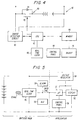
- Another embodiment of the present invention as shown in Figure 5 in which a real time clock is provided within the battery pack. The circuitry can be used to communicate the real time data to the application, that is, for example, a cellular telephone. This can be accomplished by having an extra pin on the battery pack and the application. If the battery pack is of a rechargeable type, it is possible that the battery may become totally discharged. This may cause the real time circuit to lose the real time information. In such a case, it will be possible to enter date and time information from the application.
- The cellular telephone or other applications includes a
microprocessor 50 and adisplay 52 as well as avoltage regulator 54 providing a constant voltage source to the circuit elements. A crystal element provides a 32 kHz signal to the real time clock. The battery pack shown in Fig. 5 includes areal time clock 45, analarm 58, a 32 kHz crystal, and an arithmetic and logic unit (ALU) 59. A microprocessor may be used instead of theALU 59. - The
display 52 displays the time and data obtained from thereal time clock 45 from the data line connected to themicroprocessor 50 in the application circuit. The data line is connected to a first pin provided in the battery pack which is connected to a second pin provided in the application circuit (represented in Figure 5 by a °). The built-in-alarm 58 provided in the battery pack, for example, a vibrator or a buzzer, may be activated at a predetermined time based on the real time clock information. The predetermined time may be set by acontrol panel 48 on the battery pack (Figure 4) or thecontrol panel 56 normally used in the battery charger or in the application (Figure 5). - The real time clock can also be used to activate or shut down the battery powered application in a predetermined manner. The predetermination of the shut down time can be done by a control panel on the battery pack or the control panel normally used with the application equipment. The
microprocessor 50 in the application places the application circuit in a non-operational mode, that is, it shuts off the application, when the real time clock reaches the predetermined time. - According to one embodiment, the real time clock may be used to control the recharging of the battery pack. In particular, the real time clock may provide the basis for counting the total charging time experienced by the battery pack as described above.
- An advantage achieved by the present invention occurs by adding the clock to the battery pack itself since the clock will always have the power to keep the tine correctly during charging and the back up battery or capacitor can be eliminated. By including one or more extra connections between the battery pack and the telephone or the application equipment, it is possible for the microprocessor in the application equipment to communicate with the clock circuit to inquire as to the current time, set an alarm and set the time. The connections would also enable the microprocessor to be woken up by the clock circuit in the event of an alarm.
- Another embodiment of the present invention is shown in the flow chart of Figure 6. According to this embodiment, the memory and the CPU of the battery pack, such as that shown in Figure 4, is used in conjunction with the memory and CPU in the application circuit (not shown) to make it possible for the battery powered application or the battery charger to distinguish a correct battery from a battery that is manufactured by somebody else. To prevent unauthorized manufacturers from copying this electronic circuit, the
memory unit 44 contains mathematical formula that is also known to the application circuit and stored in the memory thereof (not shown). - When the application is powered up, it retrieves the stored mathematical formula from the application memory (step 60). At the same time, the battery pack 10' retrieves the stored mathematical formula from the
battery memory unit 44. A random number is generated by the application equipment (step 62). This random number is used as the input to the mathematical formula stored in the battery pack as well as that stored in the application. The first result of the mathematical formula is calculated in the battery pack using the random number generated in step 62 (step 64). The second result of the mathematical formula is calculated in the application using the random number generated in step 62 (step 66). The result of both calculations are communicated to the application where they are compared atstep 68. If the first result is not equal to the second result, this indicates that the battery pack is a counterfeit battery pack and the application is placed in an non-operational state (step 70). If the application is placed in the non-operational state, the reason therefor may be communicated to the user by a display or alarm. If the first result equals the second result, the application is permitted to operate atstep 72. If the application is placed in the non-operational state, this reason therefore may be communicated to the user by a display or alarm. - According to another embodiment, a modular-two addition to a number hidden in the battery pack may serve to determine whether the battery pack is counterfeit. According to a preferred embodiment, the charger or application sends a number in serial form to the battery pack. The CPU in the battery pack adds a number with module-two addition and returns the results to the supervising unit, the battery charger or the application. After the new modular-two addition, the supervising unit checks whether or not the hidden number from the battery pack is a member of the accepted group of numbers.
- The foregoing description of the specific embodiments will so fully reveal the general nature of the invention that others can, by applying current knowledge, readily modify and/or adapt for various applications such specific embodiments without departing from the generic concept, and, therefore, such adaptations and modifications should and are intended to be comprehended within the meaning and range of equivalents of the disclosed embodiments. It is to be understood that the phraseology of terminology employed herein is for the purpose of description and not of limitation.
Claims (36)
- An apparatus for controlling recharging of an individual battery pack comprising:means for identifying a particular battery pack; andsupervising means for selectively allowing and preventing recharging of said individual battery pack responsive to said means for identifying.
- The apparatus according to claim 1, wherein said means for identifying comprises:at least one resistor having a particular resistance value; and
wherein said supervising means reads the particular resistance value of said at least one resistor to determine the identity of the battery pack and selectively allows or prevents recharging depending on said identity and remaining useful life of said identified battery pack. - The apparatus according to claim 1, wherein said means for identifying comprises:an individual pattern printed on a surface of said battery pack; and
wherein said supervising means reads the particular pattern printed on said battery pack to determine the identity of the battery pack and selectively allows or prevents recharging depending on said identity and remaining useful life of said identified battery pack. - The apparatus according to claim 3, wherein said pattern is printed using resistive ink.
- The apparatus according to claim 1, wherein said supervising means comprises means for determining remaining useful life of said battery pack depending on a number of charging cycles performed on said battery pack identified by said means for identifying and a level of discharging of said battery pack at each discharging cycle.
- The apparatus according to claim 5, further comprising means, responsive to said means for determining, for informing a user that the useful life of said battery pack is approaching an end or is over.
- The apparatus according to claim 6, wherein said means for informing comprises one of a light signal, a display, or an audio signal.
- The apparatus according to claim 5, further comprising means, responsive to said means for determining, for preventing further recharging cycles of the identified battery if the useful life of said battery pack is approaching an end or is over.
- The apparatus according to claim 5, further comprising:circuit means connected to said battery pack for allowing recharging of said battery pack; andmeans for short-circuiting said circuit means to prevent said battery pack from being recharged responsive to said means for determining.
- The apparatus according to claim 9, further comprising means for indicating to a user that the useful life of said battery pack is approaching an end or is over responsive to said circuit means being short-circuited.
- The apparatus according to claim 9, wherein said supervising means comprises:memory means for storing charging status of said battery pack;means for signalling said charging status to said memory means.
- The apparatus according to claim 11, wherein said means for signalling is provided in said battery pack.
- The apparatus according to claim 11, wherein said means for signalling is provided in a charging circuit.
- The apparatus according to claim 11, wherein said means for signalling signals a change in said charging status every time said battery pack is connected to a charging circuit.
- The apparatus according to claim 11, wherein said means for signalling signals a change in said charging status as a function of total charge which is given to said battery pack at every charge period.
- The apparatus according to claim 15, wherein said function is current times time.
- The apparatus according to claim 11, wherein said memory means comprises a non-volatile memory.
- The apparatus according to claim 11, wherein said memory means comprises a volatile memory requiring a small amount of current such that said battery pack can supply power to said memory means regardless of the charging condition of said battery pack.
- The apparatus according to claim 11, wherein said memory means comprises a volatile memory connected to an external power source.
- The apparatus according to claim 15, wherein said memory means comprises a volatile memory connected to an external power source.
- The apparatus according to claim 11, wherein said means for signalling signals a change in said charging status every time said battery pack is connected to a discharging circuit.
- The apparatus according to claim 1, further comprising:a real-time clock provided in said battery pack; andmeans for providing real-time clock information from said real-time clock to an application circuit to which said battery pack is connected.
- The apparatus according to claim 22, wherein said means for providing comprises:first pin means provided on said battery pack; andsecond pin means provided on said application circuit adapted to be connected to said first pin means.
- The apparatus according to claim 22, further comprising means for entering time and date information to said real-time clock.
- The apparatus according to claim 22, further comprising means provided in said application circuit for shutting off said application circuit responsive to said real-time clock.
- The apparatus according to claim 22, wherein said supervising means comprises means for controlling recharging of said battery pack using said real-time clock.
- The apparatus according to claim 22, further comprising a display provided on said battery pack for displaying time and date information.
- The apparatus according to claim 22, further comprising alarm circuit means provided in said battery pack for setting off an alarm at a predetermined time.
- The apparatus according to claim 22, further comprising a control panel for entering said predetermined time into said alarm circuit means.
- The apparatus according to claim 29, wherein said control panel is provided in said battery pack.
- The apparatus according to claim 29, wherein said control panel is provided in said application circuit.
- The apparatus according to claim 28, wherein said alarm circuit means is selected from one of an audio alarm, a vibrating alarm, and a visual alarm.
- The apparatus according to claim 1, further comprising:means for verifying the authenticity of a battery pack which has been connected to an application circuit; andmeans for placing said application circuit in an non-operational state responsive to said means for verifying.
- The apparatus according to claim 33, wherein said means for verifying comprises:means for storing a predetermined mathematical formula provided in said battery pack and in said application circuit;means for generating a random number;means for calculating a first result of said mathematical formula in said battery pack using said random number;means for calculating a second result of said mathematical formula in said application circuit using said random number;means for comparing said first result to said second result and outputting a verification signal; and
wherein said means for placing places said application circuit in the non-operational state when said verification signal indicates that said first result does not equal said second result. - The apparatus according to claim 34, further comprising means for indicating that said battery pack is not authentic when said verification signal indicates that said first result does not equal said second result.
- The apparatus according to claim 35, wherein said application circuit is a recharging circuit.
Applications Claiming Priority (3)
| Application Number | Priority Date | Filing Date | Title |
|---|---|---|---|
| US213703 | 1994-03-15 | ||
| US08/213,073 US5608306A (en) | 1994-03-15 | 1994-03-15 | Rechargeable battery pack with identification circuit, real time clock and authentication capability |
| EP95850057A EP0673103A1 (en) | 1994-03-15 | 1995-03-14 | Rechargeable battery pack with identification circuit, real time clock and authentication capability |
Related Parent Applications (1)
| Application Number | Title | Priority Date | Filing Date |
|---|---|---|---|
| EP95850057A Division EP0673103A1 (en) | 1994-03-15 | 1995-03-14 | Rechargeable battery pack with identification circuit, real time clock and authentication capability |
Publications (3)
| Publication Number | Publication Date |
|---|---|
| EP0984540A2 true EP0984540A2 (en) | 2000-03-08 |
| EP0984540A3 EP0984540A3 (en) | 2000-11-02 |
| EP0984540B1 EP0984540B1 (en) | 2004-08-18 |
Family
ID=22793644
Family Applications (4)
| Application Number | Title | Priority Date | Filing Date |
|---|---|---|---|
| EP99119973A Expired - Lifetime EP0984542B1 (en) | 1994-03-15 | 1995-03-14 | Rechargeable battery pack with identification circuit, real time clock and authentication capability |
| EP95850057A Ceased EP0673103A1 (en) | 1994-03-15 | 1995-03-14 | Rechargeable battery pack with identification circuit, real time clock and authentication capability |
| EP99119972A Expired - Lifetime EP0984541B1 (en) | 1994-03-15 | 1995-03-14 | Rechargeable battery pack with identification circuit, real time clock and authentication capability |
| EP99119971A Expired - Lifetime EP0984540B1 (en) | 1994-03-15 | 1995-03-14 | Rechargeable battery pack with identification circuit, real time clock and authentication capability |
Family Applications Before (3)
| Application Number | Title | Priority Date | Filing Date |
|---|---|---|---|
| EP99119973A Expired - Lifetime EP0984542B1 (en) | 1994-03-15 | 1995-03-14 | Rechargeable battery pack with identification circuit, real time clock and authentication capability |
| EP95850057A Ceased EP0673103A1 (en) | 1994-03-15 | 1995-03-14 | Rechargeable battery pack with identification circuit, real time clock and authentication capability |
| EP99119972A Expired - Lifetime EP0984541B1 (en) | 1994-03-15 | 1995-03-14 | Rechargeable battery pack with identification circuit, real time clock and authentication capability |
Country Status (13)
| Country | Link |
|---|---|
| US (1) | US5608306A (en) |
| EP (4) | EP0984542B1 (en) |
| JP (1) | JP3703835B2 (en) |
| KR (1) | KR100379587B1 (en) |
| CN (4) | CN1045697C (en) |
| AT (3) | ATE274251T1 (en) |
| AU (1) | AU687175B2 (en) |
| CA (1) | CA2162861C (en) |
| DE (3) | DE69533411D1 (en) |
| FI (1) | FI955481A (en) |
| HK (1) | HK1022523A1 (en) |
| WO (1) | WO1995025375A1 (en) |
| ZA (1) | ZA952123B (en) |
Cited By (3)
| Publication number | Priority date | Publication date | Assignee | Title |
|---|---|---|---|---|
| WO2004012294A2 (en) * | 2002-07-31 | 2004-02-05 | Rayovac Corporation | Method and apparatus for detecting the presence of rechargeable batteries |
| DE102004059006A1 (en) * | 2004-12-08 | 2006-06-14 | Audia Akustik Gmbh | Charging accumulator in hearing aid involves charge controller arranged in hearing aid which is charged in receiving bowl along with transmitter device having switching mechanism, which has no contact with accumulator |
| US8847556B2 (en) | 2006-08-31 | 2014-09-30 | Semiconductor Energy Laboratory Co., Ltd. | Power storage device and semiconductor device provided with the power storage device |
Families Citing this family (117)
| Publication number | Priority date | Publication date | Assignee | Title |
|---|---|---|---|---|
| US5825155A (en) * | 1993-08-09 | 1998-10-20 | Kabushiki Kaisha Toshiba | Battery set structure and charge/ discharge control apparatus for lithium-ion battery |
| US5792138A (en) * | 1996-02-22 | 1998-08-11 | Apollo Camera, Llc | Cordless bipolar electrocautery unit with automatic power control |
| US5867008A (en) * | 1996-06-05 | 1999-02-02 | Double-Time Battery Corporation | Overcharge protection circuitry for rechargeable battery pack |
| US6625477B1 (en) * | 1996-06-12 | 2003-09-23 | Ericsson Inc. | Apparatus and method for identifying and charging batteries of different types |
| KR0181164B1 (en) * | 1996-07-06 | 1999-05-15 | 삼성전자주식회사 | Charging apparatus for variable kinds of batteries and its control method |
| US5717307A (en) * | 1996-07-24 | 1998-02-10 | Motorola, Inc. | Apparatus and method for identifying the type and brand of a battery for a portable device |
| US5814969A (en) * | 1996-09-23 | 1998-09-29 | Ericsson Inc. | Apparatus for selectively activating a plurality of devices |
| JPH10108384A (en) * | 1996-10-01 | 1998-04-24 | Uniden Corp | Battery pack and charger |
| KR100281536B1 (en) * | 1997-01-06 | 2001-02-15 | 윤종용 | Computer with Battery Detection and Control |
| WO1999000863A2 (en) * | 1997-06-27 | 1999-01-07 | Motorola Inc. | Battery charging system having lock-out circuitry |
| JP4042813B2 (en) | 1997-10-09 | 2008-02-06 | 名糖産業株式会社 | Method for producing dextran with reduced boron content |
| SE520420C2 (en) * | 1997-10-28 | 2003-07-08 | Ericsson Telefon Ab L M | Device and method for identifying battery type and for measuring battery temperature |
| EP0926798A1 (en) * | 1997-12-24 | 1999-06-30 | Nokia Mobile Phones Ltd. | Battery type determination for a radio telephone or battery charger |
| US6218806B1 (en) * | 1998-06-03 | 2001-04-17 | Black & Decker Inc. | Method and apparatus for obtaining product use information |
| DE19828560C2 (en) * | 1998-06-26 | 2000-05-25 | Fraunhofer Ges Forschung | Device for checking autonomous solar systems |
| EP0993215A1 (en) | 1998-10-05 | 2000-04-12 | Sony International (Europe) GmbH | Transmission of random access bursts with at least one message part |
| US6249105B1 (en) * | 1998-11-13 | 2001-06-19 | Neal Andrews | System and method for detecting performance components of a battery pack |
| JP2001002488A (en) * | 1999-06-17 | 2001-01-09 | Daicel Chem Ind Ltd | Composition of gas generating agent for pretensionor |
| US6191551B1 (en) * | 1999-06-30 | 2001-02-20 | Research In Motion Limited | Automatic battery detection system and method for detecting a rechargeable battery with low remaining charge |
| EP1094530A1 (en) * | 1999-10-20 | 2001-04-25 | Sony International (Europe) GmbH | Rechargeable battery pack for a mobile terminal with unique identification and time reference |
| US6252378B1 (en) | 2000-01-10 | 2001-06-26 | Snap-On Technologies, Inc. | Usage counter for portable jump-starting battery unit |
| US8788092B2 (en) | 2000-01-24 | 2014-07-22 | Irobot Corporation | Obstacle following sensor scheme for a mobile robot |
| US8412377B2 (en) | 2000-01-24 | 2013-04-02 | Irobot Corporation | Obstacle following sensor scheme for a mobile robot |
| JP2001238356A (en) * | 2000-02-22 | 2001-08-31 | Internatl Business Mach Corp <Ibm> | Power supply device, power supply controller, method for controlling power supply and computer |
| US6956348B2 (en) | 2004-01-28 | 2005-10-18 | Irobot Corporation | Debris sensor for cleaning apparatus |
| US6789205B1 (en) * | 2000-05-19 | 2004-09-07 | Motorola, Inc. | System for determining intrinsic safety status of the combination of a communication device and a battery |
| EP1199783A1 (en) * | 2000-10-16 | 2002-04-24 | Sony International (Europe) GmbH | Battery management system |
| US6690134B1 (en) | 2001-01-24 | 2004-02-10 | Irobot Corporation | Method and system for robot localization and confinement |
| US7571511B2 (en) | 2002-01-03 | 2009-08-11 | Irobot Corporation | Autonomous floor-cleaning robot |
| EP1241767B1 (en) * | 2001-03-15 | 2015-07-08 | Sony Deutschland GmbH | Real time clock synchronisation for mobile devices with rechargeable battery using the charger |
| EP1255360A1 (en) * | 2001-05-03 | 2002-11-06 | Sony International (Europe) GmbH | Battery with oscillator for mobile terminal |
| US7663333B2 (en) | 2001-06-12 | 2010-02-16 | Irobot Corporation | Method and system for multi-mode coverage for an autonomous robot |
| US8396592B2 (en) | 2001-06-12 | 2013-03-12 | Irobot Corporation | Method and system for multi-mode coverage for an autonomous robot |
| JP3672248B2 (en) * | 2001-09-19 | 2005-07-20 | インターナショナル・ビジネス・マシーンズ・コーポレーション | Electrical apparatus, computer apparatus, intelligent battery, battery diagnosis method, battery state display method, and program |
| JP3625799B2 (en) * | 2001-11-30 | 2005-03-02 | 三洋電機株式会社 | Battery pack with authenticity detection circuit |
| US9128486B2 (en) | 2002-01-24 | 2015-09-08 | Irobot Corporation | Navigational control system for a robotic device |
| US8386081B2 (en) | 2002-09-13 | 2013-02-26 | Irobot Corporation | Navigational control system for a robotic device |
| US8428778B2 (en) | 2002-09-13 | 2013-04-23 | Irobot Corporation | Navigational control system for a robotic device |
| CN100420083C (en) * | 2002-12-20 | 2008-09-17 | 北京六合万通微电子技术有限公司 | Anti-fogery system of chargeable battery |
| US7129706B2 (en) * | 2003-06-11 | 2006-10-31 | Bright Solutions, Inc. | Part tester and method |
| JP2005012663A (en) * | 2003-06-20 | 2005-01-13 | Sanyo Electric Co Ltd | Authentication system and id generator |
| FI20031089A (en) * | 2003-07-17 | 2005-01-18 | Avantone Oy | Method for identifying objects and systems for examining the contents of a brand |
| JP2005073053A (en) * | 2003-08-26 | 2005-03-17 | Sanyo Electric Co Ltd | Id confirmation unit, id generation unit and authentication system |
| JP4097582B2 (en) | 2003-09-12 | 2008-06-11 | 三洋電機株式会社 | Pack battery, electric device connectable to pack battery, and pack battery type determination method |
| JP2005151368A (en) | 2003-11-19 | 2005-06-09 | Matsushita Electric Ind Co Ltd | Authentication system |
| US7332890B2 (en) | 2004-01-21 | 2008-02-19 | Irobot Corporation | Autonomous robot auto-docking and energy management systems and methods |
| WO2005098476A1 (en) | 2004-03-29 | 2005-10-20 | Evolution Robotics, Inc. | Method and apparatus for position estimation using reflected light sources |
| JP2008508572A (en) | 2004-06-24 | 2008-03-21 | アイロボット コーポレーション | Portable robot programming and diagnostic tools |
| US8972052B2 (en) | 2004-07-07 | 2015-03-03 | Irobot Corporation | Celestial navigation system for an autonomous vehicle |
| US7706917B1 (en) | 2004-07-07 | 2010-04-27 | Irobot Corporation | Celestial navigation system for an autonomous robot |
| KR100631578B1 (en) * | 2004-07-30 | 2006-10-09 | 엘지전자 주식회사 | Methods and apparatus of discrimination poor battery for mobile phone |
| US7545147B2 (en) * | 2004-08-31 | 2009-06-09 | Eaglepicher Technologies, Llc | System and method for nondestructive testing of thermal batteries |
| KR100690729B1 (en) * | 2004-10-04 | 2007-03-09 | 엘지전자 주식회사 | Apparatus and method for controling operation of mobile communication terminal by detecting kind of battery |
| JP3765544B1 (en) | 2004-11-26 | 2006-04-12 | 株式会社ソニー・コンピュータエンタテインメント | Battery and authentication request device |
| JP3833679B2 (en) * | 2004-12-02 | 2006-10-18 | ソニー株式会社 | Battery pack and charge control method |
| US20060178170A1 (en) * | 2005-02-08 | 2006-08-10 | Samsung Electronics Co., Ltd. | Wireless communication device having battery authentication, and associated method |
| US7620476B2 (en) | 2005-02-18 | 2009-11-17 | Irobot Corporation | Autonomous surface cleaning robot for dry cleaning |
| US8392021B2 (en) | 2005-02-18 | 2013-03-05 | Irobot Corporation | Autonomous surface cleaning robot for wet cleaning |
| WO2006089307A2 (en) * | 2005-02-18 | 2006-08-24 | Irobot Corporation | Autonomous surface cleaning robot for wet and dry cleaning |
| JP3838258B2 (en) * | 2005-03-10 | 2006-10-25 | ソニー株式会社 | Battery level display method |
| US8930023B2 (en) | 2009-11-06 | 2015-01-06 | Irobot Corporation | Localization by learning of wave-signal distributions |
| JP2006271697A (en) * | 2005-03-29 | 2006-10-12 | Fujinon Corp | Electronic endoscope |
| CN1862280B (en) * | 2005-05-10 | 2013-04-24 | 电池公司 | Battery management system and device with abnormity report function |
| DE102005024227A1 (en) * | 2005-05-25 | 2006-11-30 | Audia Akustik Gmbh | Method and device for inductive charging of hearing aids |
| KR100765234B1 (en) | 2005-06-09 | 2007-10-09 | 엘지전자 주식회사 | method for charging mobile phone using authentication code, and mobile phone thereof |
| US7250612B2 (en) | 2005-09-28 | 2007-07-31 | General Electric Company | Devices and methods capable of authenticating batteries |
| EP1938170B1 (en) * | 2005-10-14 | 2014-02-26 | BlackBerry Limited | Battery pack authentication for a mobile device |
| ATE489670T1 (en) * | 2005-10-14 | 2010-12-15 | Research In Motion Ltd | MOBILE COMMUNICATION DEVICE WITH AN INTELLIGENT BATTERY SYSTEM |
| CA2564021C (en) * | 2005-10-14 | 2010-12-07 | Research In Motion Limited | Mobile device with a smart battery |
| JP2007110853A (en) * | 2005-10-14 | 2007-04-26 | Mitsumi Electric Co Ltd | Ac adapter, electronic equipment, and power system |
| KR101318010B1 (en) | 2005-10-21 | 2013-10-14 | 스트리커 코포레이션 | Battery capable of recording data regarding the sterilization of the battery and method of monitoring the sterilization of a battery |
| ES2706727T3 (en) | 2005-12-02 | 2019-04-01 | Irobot Corp | Robot system |
| US8584305B2 (en) * | 2005-12-02 | 2013-11-19 | Irobot Corporation | Modular robot |
| KR101099808B1 (en) | 2005-12-02 | 2011-12-27 | 아이로보트 코퍼레이션 | Robot system |
| EP2816434A3 (en) | 2005-12-02 | 2015-01-28 | iRobot Corporation | Autonomous coverage robot |
| KR101300493B1 (en) | 2005-12-02 | 2013-09-02 | 아이로보트 코퍼레이션 | Coverage robot mobility |
| JP5064003B2 (en) * | 2005-12-20 | 2012-10-31 | パナソニック株式会社 | Authentication system and authentication device |
| US7554288B2 (en) * | 2006-03-10 | 2009-06-30 | Atmel Corporation | Random number generator in a battery pack |
| US8296565B2 (en) * | 2006-03-27 | 2012-10-23 | Kyocera Corporation | Communication protocol for device authentication |
| US8301888B2 (en) * | 2006-03-27 | 2012-10-30 | Kyocera Corporation | System and method for generating secured authentication image files for use in device authentication |
| ATE523131T1 (en) | 2006-05-19 | 2011-09-15 | Irobot Corp | WASTE REMOVAL FROM CLEANING ROBOTS |
| US8417383B2 (en) | 2006-05-31 | 2013-04-09 | Irobot Corporation | Detecting robot stasis |
| JP2008086192A (en) * | 2006-08-31 | 2008-04-10 | Semiconductor Energy Lab Co Ltd | Storage device and semiconductor device having the storage device |
| KR101414321B1 (en) | 2007-05-09 | 2014-07-01 | 아이로보트 코퍼레이션 | Autonomous coverage robot |
| DE102007029746A1 (en) * | 2007-06-27 | 2009-01-08 | Robert Bosch Gmbh | Rechargeable energy supply device with an identification device |
| JP5151506B2 (en) * | 2008-01-28 | 2013-02-27 | 日立工機株式会社 | Battery pack, charging device and charging system for charging the same |
| FI20085456L (en) * | 2008-05-15 | 2009-11-16 | Valtion Teknillinen | Method and apparatus for identifying an electronic code |
| US8650411B2 (en) * | 2008-09-07 | 2014-02-11 | Schweitzer Engineering Laboratories Inc. | Energy management for an electronic device |
| US8120363B2 (en) | 2008-11-24 | 2012-02-21 | Cummins Power Generation Ip, Inc. | Voltage drop compensation for an electric power storage device charging system |
| KR101000550B1 (en) * | 2009-11-30 | 2010-12-14 | 정윤이 | Battery pack and active cell balancing battery management system including the same |
| CN102027628B (en) * | 2009-11-30 | 2014-05-14 | 郑润珥 | Battery pack and active cell balancing battery management system including same |
| JP2011135740A (en) | 2009-12-25 | 2011-07-07 | Makita Corp | Battery pack for power tool and battery connection device |
| US8800107B2 (en) | 2010-02-16 | 2014-08-12 | Irobot Corporation | Vacuum brush |
| US8725330B2 (en) | 2010-06-02 | 2014-05-13 | Bryan Marc Failing | Increasing vehicle security |
| JP5549479B2 (en) * | 2010-08-27 | 2014-07-16 | 株式会社デンソー | Battery management device |
| CN102859837A (en) * | 2010-12-06 | 2013-01-02 | 科达汽车公司 | Electrochemical cell balancing circuits and methods |
| WO2012132376A2 (en) * | 2011-03-25 | 2012-10-04 | Hitachi Koki Co., Ltd. | Charger and power supply system |
| US9114181B2 (en) | 2011-03-30 | 2015-08-25 | Covidien Lp | Process of cooling surgical device battery before or during high temperature sterilization |
| US8912749B2 (en) | 2011-06-01 | 2014-12-16 | Htc Corporation | Electrical apparatus and verification method for battery module thereof |
| CN102820970B (en) * | 2011-06-08 | 2016-08-03 | 宏达国际电子股份有限公司 | Electronic installation and the authentication method of battery module thereof |
| WO2013018852A1 (en) * | 2011-08-02 | 2013-02-07 | 株式会社ソニー・コンピュータエンタテインメント | Electrical device |
| KR101872472B1 (en) * | 2011-11-04 | 2018-06-29 | 삼성에스디아이 주식회사 | Battery Pack, Battery protection circuit, and battery system |
| JP5404831B2 (en) * | 2012-02-17 | 2014-02-05 | 三菱電機株式会社 | Charging system |
| EP2822428B1 (en) * | 2012-03-09 | 2019-05-22 | Unovo, LLC | Cooking appliance |
| WO2015120300A1 (en) * | 2014-02-06 | 2015-08-13 | Dichiara E Ismael | Mobile multi-charger for mobile device external batteries |
| DE102015103193A1 (en) * | 2015-03-05 | 2016-09-08 | Dr. Ing. H.C. F. Porsche Aktiengesellschaft | Method and device for setting up an on-board charger in an electrically driven vehicle |
| US10498160B2 (en) | 2015-08-03 | 2019-12-03 | Massachusetts Institute Of Technology | Efficiency maximization for device-to-device wireless charging |
| US10177589B2 (en) | 2015-11-09 | 2019-01-08 | Johnson Industries, Inc. | Battery exercising device |
| US10886765B2 (en) | 2015-11-09 | 2021-01-05 | Johnson Industries, Inc. | Lighted connector for a battery cable |
| CN108432032B (en) | 2015-11-09 | 2021-02-26 | 约翰森工业公司 | Battery operating device |
| TWI811718B (en) | 2016-03-16 | 2023-08-11 | 澳門商創科(澳門離岸商業服務)有限公司 | Power tool battery pack with wireless communication |
| US11018526B2 (en) | 2018-02-08 | 2021-05-25 | Massachusetts Institute Of Technology | Detuning for a resonant wireless power transfer system including cooperative power sharing |
| US10651687B2 (en) | 2018-02-08 | 2020-05-12 | Massachusetts Institute Of Technology | Detuning for a resonant wireless power transfer system including cryptography |
| US10459025B1 (en) | 2018-04-04 | 2019-10-29 | Schweitzer Engineering Laboratories, Inc. | System to reduce start-up times in line-mounted fault detectors |
| US11397198B2 (en) | 2019-08-23 | 2022-07-26 | Schweitzer Engineering Laboratories, Inc. | Wireless current sensor |
| US11105834B2 (en) | 2019-09-19 | 2021-08-31 | Schweitzer Engineering Laboratories, Inc. | Line-powered current measurement device |
| US20220116103A1 (en) * | 2020-10-09 | 2022-04-14 | Schweitzer Engineering Laboratories, Inc. | Wireless radio repeater for electric power distribution system |
Citations (4)
| Publication number | Priority date | Publication date | Assignee | Title |
|---|---|---|---|---|
| EP0226360A2 (en) * | 1985-12-04 | 1987-06-24 | Powerplex Technologies, Inc. | A zener diode looping element for protecting a battery cell |
| EP0394074A2 (en) * | 1989-04-21 | 1990-10-24 | Motorola, Inc. | Method and apparatus for determining battery type and modifying operating characteristics |
| US5150031A (en) * | 1988-09-30 | 1992-09-22 | Motorola, Inc. | Battery charging system |
| US5200686A (en) * | 1991-10-10 | 1993-04-06 | Motorola, Inc. | Method and apparatus for determining battery type |
Family Cites Families (35)
| Publication number | Priority date | Publication date | Assignee | Title |
|---|---|---|---|---|
| US4289836A (en) * | 1980-03-05 | 1981-09-15 | Lemelson Jerome H | Rechargeable electric battery system |
| US4363407A (en) * | 1981-01-22 | 1982-12-14 | Polaroid Corporation | Method and system for testing and sorting batteries |
| US4961043A (en) * | 1988-03-15 | 1990-10-02 | Norand Corporation | Battery conditioning system having communication with battery parameter memory means in conjunction with battery conditioning |
| US4455523A (en) * | 1982-06-07 | 1984-06-19 | Norand Corporation | Portable battery powered system |
| US4716354A (en) * | 1985-11-12 | 1987-12-29 | Norand Corporation | Automatic voltage regulator means providing a dual low power responsive and output-voltage-controlling regulator signal particularly for a plural source battery powered system |
| US4553081A (en) * | 1982-06-07 | 1985-11-12 | Norand Corporation | Portable battery powered system |
| DE3331360A1 (en) * | 1983-08-31 | 1985-03-14 | Varta Batterie Ag, 3000 Hannover | Accumulator battery with an electronic module integrated into the housing cover for functional monitoring |
| US4593409A (en) * | 1984-04-04 | 1986-06-03 | Motorola, Inc. | Transceiver protection arrangement |
| US4638237A (en) * | 1985-01-03 | 1987-01-20 | Pulse Electronics, Inc. | Battery condition indicator |
| CN85202831U (en) * | 1985-07-11 | 1987-05-20 | 朱汉雄 | Printed electric resistance |
| US4680527A (en) * | 1986-08-06 | 1987-07-14 | Motorola, Inc. | Electrical battery including apparatus for current sensing |
| US4743831A (en) * | 1986-09-12 | 1988-05-10 | Troxler Electronic Laboratories, Inc. | Apparatus and method for indicating remaining battery life in a battery powered device |
| US4700375A (en) * | 1986-10-10 | 1987-10-13 | Motorola, Inc. | Battery charging, reset, and data transfer system |
| US4888702A (en) * | 1987-08-20 | 1989-12-19 | Integrated Power Corporation | Photovoltaic system controller |
| CN2044379U (en) * | 1988-03-28 | 1989-09-13 | 东北工学院 | Monitor for accumulator voltage |
| US4965738A (en) * | 1988-05-03 | 1990-10-23 | Anton/Bauer, Inc. | Intelligent battery system |
| DE3815001A1 (en) * | 1988-05-03 | 1989-11-16 | Ullmann Ulo Werk | DEVICE FOR CHARGING ACCUMULATORS |
| DE3823038C2 (en) * | 1988-07-07 | 1996-07-18 | Diehl Gmbh & Co | Procedure for monitoring the state of charge of a battery |
| JPH02294231A (en) * | 1989-05-01 | 1990-12-05 | Fujikura Ltd | Charging apparatus for interchangeable charging battery pack |
| US5029188A (en) * | 1989-11-03 | 1991-07-02 | Joyner Engineers And Trainers | Apparatus for monitoring operation cycles of an electrically actuated device |
| US5023591A (en) * | 1989-11-15 | 1991-06-11 | Allen V. Edwards | Anti-theft control apparatus |
| US5057383A (en) * | 1990-03-30 | 1991-10-15 | Anton/Bauer, Inc | Battery system |
| JPH0496627A (en) * | 1990-08-11 | 1992-03-30 | Canon Inc | Power supply circuit having charging function and printer |
| US5111128A (en) * | 1990-12-17 | 1992-05-05 | Motorola, Inc. | Battery identification apparatus |
| US5136620A (en) * | 1990-12-31 | 1992-08-04 | Eaves Stephen S | Battery charge cycle counter |
| JP3202761B2 (en) * | 1991-05-28 | 2001-08-27 | 松下電工株式会社 | Charge control device |
| US5206097A (en) * | 1991-06-05 | 1993-04-27 | Motorola, Inc. | Battery package having a communication window |
| US5184059A (en) * | 1991-09-16 | 1993-02-02 | Motorola, Inc. | Expanded battery capacity identification scheme and apparatus |
| JP3244737B2 (en) * | 1991-12-24 | 2002-01-07 | 松下電工株式会社 | Battery life notification device |
| JPH05198293A (en) * | 1992-01-20 | 1993-08-06 | Sanyo Electric Co Ltd | Battery pack |
| US5248929A (en) * | 1992-04-30 | 1993-09-28 | Murata Machinery, Ltd. | Battery time monitor for cellular telephone |
| JP3289320B2 (en) * | 1992-06-30 | 2002-06-04 | ソニー株式会社 | battery pack |
| JPH0646533A (en) * | 1992-07-23 | 1994-02-18 | Nec Corp | Charger for nickel cadmiun battery |
| US5349535A (en) * | 1992-10-20 | 1994-09-20 | Digicomp Research Corporation | Battery condition monitoring and recording system for electric vehicles |
| JPH06186310A (en) * | 1992-12-18 | 1994-07-08 | Fujitsu Ltd | Device for estimating residual quantity of battery |
-
1994
- 1994-03-15 US US08/213,073 patent/US5608306A/en not_active Expired - Lifetime
-
1995
- 1995-03-14 AT AT99119972T patent/ATE274251T1/en not_active IP Right Cessation
- 1995-03-14 DE DE69533411T patent/DE69533411D1/en not_active Expired - Lifetime
- 1995-03-14 EP EP99119973A patent/EP0984542B1/en not_active Expired - Lifetime
- 1995-03-14 DE DE69533410T patent/DE69533410T2/en not_active Expired - Lifetime
- 1995-03-14 EP EP95850057A patent/EP0673103A1/en not_active Ceased
- 1995-03-14 EP EP99119972A patent/EP0984541B1/en not_active Expired - Lifetime
- 1995-03-14 AT AT99119973T patent/ATE274252T1/en not_active IP Right Cessation
- 1995-03-14 AT AT99119971T patent/ATE274250T1/en not_active IP Right Cessation
- 1995-03-14 EP EP99119971A patent/EP0984540B1/en not_active Expired - Lifetime
- 1995-03-14 DE DE69533412T patent/DE69533412T2/en not_active Expired - Lifetime
- 1995-03-15 JP JP52414395A patent/JP3703835B2/en not_active Expired - Lifetime
- 1995-03-15 WO PCT/US1995/003185 patent/WO1995025375A1/en active Application Filing
- 1995-03-15 KR KR1019950705095A patent/KR100379587B1/en not_active IP Right Cessation
- 1995-03-15 CA CA002162861A patent/CA2162861C/en not_active Expired - Lifetime
- 1995-03-15 CN CN95190368A patent/CN1045697C/en not_active Expired - Lifetime
- 1995-03-15 AU AU19980/95A patent/AU687175B2/en not_active Expired
- 1995-03-15 ZA ZA952123A patent/ZA952123B/en unknown
- 1995-11-14 FI FI955481A patent/FI955481A/en not_active Application Discontinuation
-
1998
- 1998-09-01 CN CN98118887A patent/CN1216871A/en active Pending
- 1998-09-01 CN CN98118888A patent/CN1107988C/en not_active Expired - Lifetime
-
1999
- 1999-02-06 CN CN99102109A patent/CN1119668C/en not_active Expired - Lifetime
-
2000
- 2000-03-07 HK HK00101433A patent/HK1022523A1/en not_active IP Right Cessation
Patent Citations (4)
| Publication number | Priority date | Publication date | Assignee | Title |
|---|---|---|---|---|
| EP0226360A2 (en) * | 1985-12-04 | 1987-06-24 | Powerplex Technologies, Inc. | A zener diode looping element for protecting a battery cell |
| US5150031A (en) * | 1988-09-30 | 1992-09-22 | Motorola, Inc. | Battery charging system |
| EP0394074A2 (en) * | 1989-04-21 | 1990-10-24 | Motorola, Inc. | Method and apparatus for determining battery type and modifying operating characteristics |
| US5200686A (en) * | 1991-10-10 | 1993-04-06 | Motorola, Inc. | Method and apparatus for determining battery type |
Cited By (8)
| Publication number | Priority date | Publication date | Assignee | Title |
|---|---|---|---|---|
| WO2004012294A2 (en) * | 2002-07-31 | 2004-02-05 | Rayovac Corporation | Method and apparatus for detecting the presence of rechargeable batteries |
| WO2004012294A3 (en) * | 2002-07-31 | 2005-01-20 | Ray O Vac Corp | Method and apparatus for detecting the presence of rechargeable batteries |
| DE102004059006A1 (en) * | 2004-12-08 | 2006-06-14 | Audia Akustik Gmbh | Charging accumulator in hearing aid involves charge controller arranged in hearing aid which is charged in receiving bowl along with transmitter device having switching mechanism, which has no contact with accumulator |
| US8847556B2 (en) | 2006-08-31 | 2014-09-30 | Semiconductor Energy Laboratory Co., Ltd. | Power storage device and semiconductor device provided with the power storage device |
| US9270229B2 (en) | 2006-08-31 | 2016-02-23 | Semiconductor Energy Laboratory Co., Ltd. | Power storage device and semiconductor device provided with the power storage device |
| US9620988B2 (en) | 2006-08-31 | 2017-04-11 | Semiconductor Energy Laboratory Co., Ltd. | Power storage device and semiconductor device provided with the power storage device |
| US9985464B2 (en) | 2006-08-31 | 2018-05-29 | Semiconductor Energy Laboratory Co., Ltd. | Power storage device and semiconductor device provided with the power storage device |
| US10666093B2 (en) | 2006-08-31 | 2020-05-26 | Semiconductor Energy Laboratory Co., Ltd. | Power storage device and semiconductor device provided with the power storage device |
Also Published As
Similar Documents
| Publication | Publication Date | Title |
|---|---|---|
| US5608306A (en) | Rechargeable battery pack with identification circuit, real time clock and authentication capability | |
| AU750287B2 (en) | Battery protection circuit and battery pack including a protection circuit | |
| US7777612B2 (en) | Theft prevention device for automotive vehicle service centers | |
| US7498767B2 (en) | Centralized data storage of condition of a storage battery at its point of sale | |
| US20050225446A1 (en) | Theft prevention device for automotive vehicle service centers | |
| EP0546872A1 (en) | Improvements in or relating to batteries and battery systems | |
| US20060038572A1 (en) | System for automatically gathering battery information for use during battery testing/charging | |
| WO1999060683A1 (en) | Battery pack protection circuit | |
| EP0545747B1 (en) | Improvements in or relating to batteries and battery systems | |
| US20080079592A1 (en) | Battery voltage monitor | |
| JP3296624B2 (en) | Electrical equipment that determines the type of battery pack | |
| MXPA95004666A (en) | Rechargeable battery pack with deidentification circuit, real time clock and autenticac capacity | |
| WO1990001221A1 (en) | Monitoring device for electric storage battery and configuration therefor | |
| JP2003257497A (en) | Secondary battery and equipment using secondary battery as well as secondary battery charger | |
| CN209037417U (en) | Charging equipment resetting detection device and charging pile | |
| JP4196769B2 (en) | Electronic license plate system and electronic license plate | |
| JPH05288817A (en) | Alarm device for secondary battery | |
| JPH10243564A (en) | Unconnected terminal detecting circuit | |
| KR20050018147A (en) | Battery included secret identification code | |
| WO1990006564A1 (en) | Electric key apparatus |
Legal Events
| Date | Code | Title | Description |
|---|---|---|---|
| PUAI | Public reference made under article 153(3) epc to a published international application that has entered the european phase |
Free format text: ORIGINAL CODE: 0009012 |
|
| AC | Divisional application: reference to earlier application |
Ref document number: 673103 Country of ref document: EP |
|
| AK | Designated contracting states |
Kind code of ref document: A2 Designated state(s): AT BE CH DE DK ES FR GB GR IE IT LI LU NL PT SE |
|
| RIN1 | Information on inventor provided before grant (corrected) |
Inventor name: HOLMQUIST, BO PETER Inventor name: HANSSON, HANS MAGNUS Inventor name: RYDBECK, NILS RUTGER CARL |
|
| RIN1 | Information on inventor provided before grant (corrected) |
Inventor name: HOLMQVIST, BO PETER Inventor name: HANSSON, HANS MAGNUS Inventor name: RYDBECK, NILS RUTGER CARL |
|
| PUAL | Search report despatched |
Free format text: ORIGINAL CODE: 0009013 |
|
| AK | Designated contracting states |
Kind code of ref document: A3 Designated state(s): AT BE CH DE DK ES FR GB GR IE IT LI LU NL PT SE |
|
| RIC1 | Information provided on ipc code assigned before grant |
Free format text: 7H 02J 7/00 A, 7H 04Q 7/32 B |
|
| 17P | Request for examination filed |
Effective date: 20010423 |
|
| AKX | Designation fees paid |
Free format text: AT BE CH DE DK ES FR GB GR IE IT LI LU NL PT SE |
|
| 17Q | First examination report despatched |
Effective date: 20030701 |
|
| RAP1 | Party data changed (applicant data changed or rights of an application transferred) |
Owner name: ERICSSON INC. |
|
| GRAP | Despatch of communication of intention to grant a patent |
Free format text: ORIGINAL CODE: EPIDOSNIGR1 |
|
| GRAS | Grant fee paid |
Free format text: ORIGINAL CODE: EPIDOSNIGR3 |
|
| GRAA | (expected) grant |
Free format text: ORIGINAL CODE: 0009210 |
|
| AC | Divisional application: reference to earlier application |
Ref document number: 0673103 Country of ref document: EP Kind code of ref document: P |
|
| AK | Designated contracting states |
Kind code of ref document: B1 Designated state(s): AT BE CH DE DK ES FR GB GR IE IT LI LU NL PT SE |
|
| PG25 | Lapsed in a contracting state [announced via postgrant information from national office to epo] |
Ref country code: NL Free format text: LAPSE BECAUSE OF FAILURE TO SUBMIT A TRANSLATION OF THE DESCRIPTION OR TO PAY THE FEE WITHIN THE PRESCRIBED TIME-LIMIT Effective date: 20040818 Ref country code: LI Free format text: LAPSE BECAUSE OF FAILURE TO SUBMIT A TRANSLATION OF THE DESCRIPTION OR TO PAY THE FEE WITHIN THE PRESCRIBED TIME-LIMIT Effective date: 20040818 Ref country code: IT Free format text: LAPSE BECAUSE OF FAILURE TO SUBMIT A TRANSLATION OF THE DESCRIPTION OR TO PAY THE FEE WITHIN THE PRESCRIBED TIME-LIMIT;WARNING: LAPSES OF ITALIAN PATENTS WITH EFFECTIVE DATE BEFORE 2007 MAY HAVE OCCURRED AT ANY TIME BEFORE 2007. THE CORRECT EFFECTIVE DATE MAY BE DIFFERENT FROM THE ONE RECORDED. Effective date: 20040818 Ref country code: FR Free format text: LAPSE BECAUSE OF FAILURE TO SUBMIT A TRANSLATION OF THE DESCRIPTION OR TO PAY THE FEE WITHIN THE PRESCRIBED TIME-LIMIT Effective date: 20040818 Ref country code: CH Free format text: LAPSE BECAUSE OF FAILURE TO SUBMIT A TRANSLATION OF THE DESCRIPTION OR TO PAY THE FEE WITHIN THE PRESCRIBED TIME-LIMIT Effective date: 20040818 Ref country code: BE Free format text: LAPSE BECAUSE OF FAILURE TO SUBMIT A TRANSLATION OF THE DESCRIPTION OR TO PAY THE FEE WITHIN THE PRESCRIBED TIME-LIMIT Effective date: 20040818 Ref country code: AT Free format text: LAPSE BECAUSE OF FAILURE TO SUBMIT A TRANSLATION OF THE DESCRIPTION OR TO PAY THE FEE WITHIN THE PRESCRIBED TIME-LIMIT Effective date: 20040818 |
|
| REG | Reference to a national code |
Ref country code: GB Ref legal event code: FG4D |
|
| REG | Reference to a national code |
Ref country code: CH Ref legal event code: EP |
|
| REG | Reference to a national code |
Ref country code: IE Ref legal event code: FG4D |
|
| REF | Corresponds to: |
Ref document number: 69533410 Country of ref document: DE Date of ref document: 20040923 Kind code of ref document: P |
|
| PG25 | Lapsed in a contracting state [announced via postgrant information from national office to epo] |
Ref country code: SE Free format text: LAPSE BECAUSE OF FAILURE TO SUBMIT A TRANSLATION OF THE DESCRIPTION OR TO PAY THE FEE WITHIN THE PRESCRIBED TIME-LIMIT Effective date: 20041118 Ref country code: GR Free format text: LAPSE BECAUSE OF FAILURE TO SUBMIT A TRANSLATION OF THE DESCRIPTION OR TO PAY THE FEE WITHIN THE PRESCRIBED TIME-LIMIT Effective date: 20041118 Ref country code: DK Free format text: LAPSE BECAUSE OF FAILURE TO SUBMIT A TRANSLATION OF THE DESCRIPTION OR TO PAY THE FEE WITHIN THE PRESCRIBED TIME-LIMIT Effective date: 20041118 |
|
| PG25 | Lapsed in a contracting state [announced via postgrant information from national office to epo] |
Ref country code: ES Free format text: LAPSE BECAUSE OF FAILURE TO SUBMIT A TRANSLATION OF THE DESCRIPTION OR TO PAY THE FEE WITHIN THE PRESCRIBED TIME-LIMIT Effective date: 20041129 |
|
| NLV1 | Nl: lapsed or annulled due to failure to fulfill the requirements of art. 29p and 29m of the patents act | ||
| REG | Reference to a national code |
Ref country code: CH Ref legal event code: PL |
|
| PG25 | Lapsed in a contracting state [announced via postgrant information from national office to epo] |
Ref country code: LU Free format text: LAPSE BECAUSE OF NON-PAYMENT OF DUE FEES Effective date: 20050314 Ref country code: IE Free format text: LAPSE BECAUSE OF NON-PAYMENT OF DUE FEES Effective date: 20050314 Ref country code: GB Free format text: LAPSE BECAUSE OF NON-PAYMENT OF DUE FEES Effective date: 20050314 |
|
| PLBE | No opposition filed within time limit |
Free format text: ORIGINAL CODE: 0009261 |
|
| STAA | Information on the status of an ep patent application or granted ep patent |
Free format text: STATUS: NO OPPOSITION FILED WITHIN TIME LIMIT |
|
| 26N | No opposition filed |
Effective date: 20050519 |
|
| EN | Fr: translation not filed | ||
| GBPC | Gb: european patent ceased through non-payment of renewal fee |
Effective date: 20050314 |
|
| REG | Reference to a national code |
Ref country code: IE Ref legal event code: MM4A |
|
| PG25 | Lapsed in a contracting state [announced via postgrant information from national office to epo] |
Ref country code: PT Free format text: LAPSE BECAUSE OF NON-PAYMENT OF DUE FEES Effective date: 20050118 |
|
| PGFP | Annual fee paid to national office [announced via postgrant information from national office to epo] |
Ref country code: DE Payment date: 20140327 Year of fee payment: 20 |
|
| REG | Reference to a national code |
Ref country code: DE Ref legal event code: R071 Ref document number: 69533410 Country of ref document: DE |
|
| REG | Reference to a national code |
Ref country code: DE Ref legal event code: R071 Ref document number: 69533410 Country of ref document: DE |