EP0991124A2 - DRAM memory array with four cells per bit line contact - Google Patents
DRAM memory array with four cells per bit line contact Download PDFInfo
- Publication number
- EP0991124A2 EP0991124A2 EP99116439A EP99116439A EP0991124A2 EP 0991124 A2 EP0991124 A2 EP 0991124A2 EP 99116439 A EP99116439 A EP 99116439A EP 99116439 A EP99116439 A EP 99116439A EP 0991124 A2 EP0991124 A2 EP 0991124A2
- Authority
- EP
- European Patent Office
- Prior art keywords
- wordlines
- semiconductor memory
- recited
- cell
- capacitors
- Prior art date
- Legal status (The legal status is an assumption and is not a legal conclusion. Google has not performed a legal analysis and makes no representation as to the accuracy of the status listed.)
- Withdrawn
Links
Images


Classifications
-
- H—ELECTRICITY
- H01—ELECTRIC ELEMENTS
- H01L—SEMICONDUCTOR DEVICES NOT COVERED BY CLASS H10
- H01L27/00—Devices consisting of a plurality of semiconductor or other solid-state components formed in or on a common substrate
- H01L27/02—Devices consisting of a plurality of semiconductor or other solid-state components formed in or on a common substrate including semiconductor components specially adapted for rectifying, oscillating, amplifying or switching and having at least one potential-jump barrier or surface barrier; including integrated passive circuit elements with at least one potential-jump barrier or surface barrier
- H01L27/04—Devices consisting of a plurality of semiconductor or other solid-state components formed in or on a common substrate including semiconductor components specially adapted for rectifying, oscillating, amplifying or switching and having at least one potential-jump barrier or surface barrier; including integrated passive circuit elements with at least one potential-jump barrier or surface barrier the substrate being a semiconductor body
- H01L27/10—Devices consisting of a plurality of semiconductor or other solid-state components formed in or on a common substrate including semiconductor components specially adapted for rectifying, oscillating, amplifying or switching and having at least one potential-jump barrier or surface barrier; including integrated passive circuit elements with at least one potential-jump barrier or surface barrier the substrate being a semiconductor body including a plurality of individual components in a repetitive configuration
-
- H—ELECTRICITY
- H10—SEMICONDUCTOR DEVICES; ELECTRIC SOLID-STATE DEVICES NOT OTHERWISE PROVIDED FOR
- H10B—ELECTRONIC MEMORY DEVICES
- H10B12/00—Dynamic random access memory [DRAM] devices
-
- H—ELECTRICITY
- H10—SEMICONDUCTOR DEVICES; ELECTRIC SOLID-STATE DEVICES NOT OTHERWISE PROVIDED FOR
- H10B—ELECTRONIC MEMORY DEVICES
- H10B12/00—Dynamic random access memory [DRAM] devices
- H10B12/30—DRAM devices comprising one-transistor - one-capacitor [1T-1C] memory cells
-
- H—ELECTRICITY
- H10—SEMICONDUCTOR DEVICES; ELECTRIC SOLID-STATE DEVICES NOT OTHERWISE PROVIDED FOR
- H10B—ELECTRONIC MEMORY DEVICES
- H10B12/00—Dynamic random access memory [DRAM] devices
- H10B12/30—DRAM devices comprising one-transistor - one-capacitor [1T-1C] memory cells
- H10B12/34—DRAM devices comprising one-transistor - one-capacitor [1T-1C] memory cells the transistor being at least partially in a trench in the substrate
-
- H—ELECTRICITY
- H01—ELECTRIC ELEMENTS
- H01L—SEMICONDUCTOR DEVICES NOT COVERED BY CLASS H10
- H01L28/00—Passive two-terminal components without a potential-jump or surface barrier for integrated circuits; Details thereof; Multistep manufacturing processes therefor
- H01L28/20—Resistors
-
- H—ELECTRICITY
- H10—SEMICONDUCTOR DEVICES; ELECTRIC SOLID-STATE DEVICES NOT OTHERWISE PROVIDED FOR
- H10B—ELECTRONIC MEMORY DEVICES
- H10B12/00—Dynamic random access memory [DRAM] devices
- H10B12/30—DRAM devices comprising one-transistor - one-capacitor [1T-1C] memory cells
- H10B12/48—Data lines or contacts therefor
- H10B12/488—Word lines
-
- Y—GENERAL TAGGING OF NEW TECHNOLOGICAL DEVELOPMENTS; GENERAL TAGGING OF CROSS-SECTIONAL TECHNOLOGIES SPANNING OVER SEVERAL SECTIONS OF THE IPC; TECHNICAL SUBJECTS COVERED BY FORMER USPC CROSS-REFERENCE ART COLLECTIONS [XRACs] AND DIGESTS
- Y10—TECHNICAL SUBJECTS COVERED BY FORMER USPC
- Y10S—TECHNICAL SUBJECTS COVERED BY FORMER USPC CROSS-REFERENCE ART COLLECTIONS [XRACs] AND DIGESTS
- Y10S257/00—Active solid-state devices, e.g. transistors, solid-state diodes
- Y10S257/905—Plural dram cells share common contact or common trench
Abstract
Description
A silicon wafer is processed by a series of process steps beginning with the formation of a plurality of
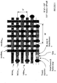
Next the first wordline level zero (wordline level 0) 11 or so called gate conductor (GC) stacks are depositioned as shown in figure 4 running directly over the
Claims (19)
- A semiconductor memory which comprises:a first plurality of wordlines and a second plurality of wordlines, said first plurality of wordlines extending mainly in a plane which is different from the plane in which said second plurality of wordlines mainly extend.
- A semiconductor memory as recited in claim 1 which includes a plurality of capacitors that can be selectively coupled to associated ones of said first and second plurality of wordlines, said capacitors consisting of trench capacitors, stacked capacitors, or a combination thereof.
- A semiconductor memory as recited in claim 1 wherein said first plurality of wordlines is orthogonal to said second plurality of wordlines.
- A semiconductor memory as recited in claim 1 wherein said field effect transistors consist of vertical or horizontal devices.
- A semiconductor memory as recited in claim 1 wherein the surface area occupied per cell is 6.25f2.
- A semiconductor memory which includes a cell-quadropole that comprises four transistor gates being disposed around the periphery of a bitline stud, each cell quadropole including four field effect transistors and four cell capacitors, a drain/source region of each field effect transistor being connected to an associated cell capacitor by a strap.
- A semiconductor memory as recited in claim 6 wherein said memory is implemented in a semiconductor substrate and said strap is buried within said semiconductor substrate.
- A semiconductor memory as recited in claim 6 wherein said memory is implemented in a semiconductor substrate and the field effect transistors are fabricated as horizontal or vertical devices or a combination thereof.
- A semiconductor memory as recited in claim 6 which further includes a plurality of first wordlines, and a plurality of second wordlines, said plurality of first wordlines extending mainly in a plane different from that in which said plurality of second wordlines extend.
- A semiconductor memory as recited in claim 9 wherein said plurality of first first wordlines is disposed substantially perpendicularly to said said plurality of second wordlines.
- A semiconductor memory as recited in claim 6 which further includes bitlines which extend mainly in a plane different from that in which said plurality of first and second wordlines lie and disposed orthogonally to said second plurality of wordlines.
- A semiconductor memory as recited in claim 6 wherein said cell capacitors consists of a one of a trench capacitor, a stacked capacitor, a trench/stacked capacitor or a combination thereof.
- A semiconductor memory as recited in claim 1 wherein the surface area occupied per cell is 6.25f2.
- A method of fabricating a semiconductor memory comprising:placing a gate oxide layer over a semiconductor substrate;placing a silicon nitride layer over said gate oxide layer;placing a BPSG fill layer over said silicon nitride layer; etching a plurality of holes in said BPSG fill layer, said silicon nitride serving as an etch stop;performing a silicon nitride strip so as to expose said gate oxide in said holes; andfilling said plurality of holes with polysilicon which is of a thickness substantially less than each hole.
- A method of fabricating a semiconductor memory as recited in claim 14 which further includes the step of metal layer creation using processing whcih consists of reactive ion etching techniques, Damascene techniques, or a combination thereof.
- A semiconductor memory which includes a first plurality of wordlines and a second plurality of wordlines , said first plurality of wordlines being disposed orthogonally to said second plurality of wordlines.
- A semiconductor memory as recited in claim 16 which further includes a plurality of cell capacitors which can be selectively coupled to ones of said first and second plurality of wordlines.
- A semiconductor memory as recited in claim 17 wherein each said cell capacitor forms at least a portion of a device fabricated as a stacked device.
- A semiconductor memory as recited in claim 17 wherein each said capacitor forms at least a portion of a device fabricated as a trench device.
Applications Claiming Priority (2)
| Application Number | Priority Date | Filing Date | Title |
|---|---|---|---|
| US163670 | 1988-03-03 | ||
| US09/163,670 US6188095B1 (en) | 1998-09-30 | 1998-09-30 | 6¼ f2 DRAM cell structure with four nodes per bitline-stud and two topological wordline levels |
Publications (2)
| Publication Number | Publication Date |
|---|---|
| EP0991124A2 true EP0991124A2 (en) | 2000-04-05 |
| EP0991124A3 EP0991124A3 (en) | 2005-12-14 |
Family
ID=22591060
Family Applications (1)
| Application Number | Title | Priority Date | Filing Date |
|---|---|---|---|
| EP99116439A Withdrawn EP0991124A3 (en) | 1998-09-30 | 1999-08-21 | DRAM memory array with four cells per bit line contact |
Country Status (6)
| Country | Link |
|---|---|
| US (1) | US6188095B1 (en) |
| EP (1) | EP0991124A3 (en) |
| JP (1) | JP2000114496A (en) |
| KR (1) | KR20000023521A (en) |
| CN (1) | CN1225027C (en) |
| TW (1) | TW464871B (en) |
Cited By (1)
| Publication number | Priority date | Publication date | Assignee | Title |
|---|---|---|---|---|
| DE102006048587A1 (en) * | 2006-09-22 | 2008-04-03 | Qimonda Ag | Memory array and method of fabricating a memory array |
Families Citing this family (14)
| Publication number | Priority date | Publication date | Assignee | Title |
|---|---|---|---|---|
| US6331733B1 (en) | 1999-08-10 | 2001-12-18 | Easic Corporation | Semiconductor device |
| US6667502B1 (en) * | 1999-08-31 | 2003-12-23 | Micron Technology, Inc. | Structurally-stabilized capacitors and method of making of same |
| US6570211B1 (en) * | 2002-06-26 | 2003-05-27 | Advanced Micro Devices, Inc. | 2Bit/cell architecture for floating gate flash memory product and associated method |
| KR100866710B1 (en) * | 2002-07-18 | 2008-11-03 | 주식회사 하이닉스반도체 | Method for forming a word line of semiconductor device |
| US6727540B2 (en) * | 2002-08-23 | 2004-04-27 | International Business Machines Corporation | Structure and method of fabricating embedded DRAM having a vertical device array and a bordered bitline contact |
| KR100539276B1 (en) | 2003-04-02 | 2005-12-27 | 삼성전자주식회사 | Semiconductor device having a gate line and Method of manufacturing the same |
| US7161226B2 (en) * | 2003-10-20 | 2007-01-09 | Industrial Technology Research Institute | Multi-layered complementary wire structure and manufacturing method thereof |
| JP2005285971A (en) * | 2004-03-29 | 2005-10-13 | Nec Electronics Corp | Semiconductor device |
| US7501676B2 (en) * | 2005-03-25 | 2009-03-10 | Micron Technology, Inc. | High density semiconductor memory |
| US8310859B2 (en) * | 2008-09-30 | 2012-11-13 | Samsung Electronics Co., Ltd. | Semiconductor memory device having balancing capacitors |
| JP5653001B2 (en) * | 2009-03-16 | 2015-01-14 | ピーエスフォー ルクスコ エスエイアールエルPS4 Luxco S.a.r.l. | Semiconductor device and method of arranging compensation capacitance of semiconductor device |
| US8872344B2 (en) * | 2010-06-09 | 2014-10-28 | Texas Instruments Incorporated | Conductive via structures for routing porosity and low via resistance, and processes of making |
| KR101119038B1 (en) * | 2011-06-01 | 2012-03-16 | 주식회사 오킨스전자 | Supporter having stacking structure for semiconductor package |
| US10834611B1 (en) * | 2019-09-05 | 2020-11-10 | International Business Machines Corporation | Network availability notification in predefined travel scenarios |
Citations (5)
| Publication number | Priority date | Publication date | Assignee | Title |
|---|---|---|---|---|
| US5250831A (en) * | 1990-03-28 | 1993-10-05 | Mitsubishi Denki Kabushiki Kaisha | DRAM device having a memory cell array of a divided bit line type |
| JPH07202022A (en) * | 1993-12-28 | 1995-08-04 | Nippon Steel Corp | Semiconductor storage device |
| US5600591A (en) * | 1992-04-24 | 1997-02-04 | Mitsubishi Denki Kabushiki Kaisha | Dynamic random access memory and manufacturing method thereof |
| US5770874A (en) * | 1994-11-14 | 1998-06-23 | Nippon Steel Corporation | High density semiconductor memory device |
| US5812443A (en) * | 1995-06-09 | 1998-09-22 | Hyundai Electronics Industries Co., Ltd. | Memory integrated circuit and methods for manufacturing the same |
Family Cites Families (4)
| Publication number | Priority date | Publication date | Assignee | Title |
|---|---|---|---|---|
| JPH03188668A (en) * | 1989-12-18 | 1991-08-16 | Mitsubishi Electric Corp | Semiconductor storage device |
| US5838038A (en) * | 1992-09-22 | 1998-11-17 | Kabushiki Kaisha Toshiba | Dynamic random access memory device with the combined open/folded bit-line pair arrangement |
| JPH08227982A (en) * | 1994-11-14 | 1996-09-03 | Nippon Steel Corp | High density semiconductor memory device |
| JP2950265B2 (en) * | 1996-07-30 | 1999-09-20 | 日本電気株式会社 | Semiconductor storage device |
-
1998
- 1998-09-30 US US09/163,670 patent/US6188095B1/en not_active Expired - Lifetime
-
1999
- 1999-08-21 EP EP99116439A patent/EP0991124A3/en not_active Withdrawn
- 1999-09-29 KR KR1019990041695A patent/KR20000023521A/en not_active Application Discontinuation
- 1999-09-29 TW TW088116719A patent/TW464871B/en not_active IP Right Cessation
- 1999-09-30 CN CNB991208501A patent/CN1225027C/en not_active Expired - Fee Related
- 1999-09-30 JP JP11280142A patent/JP2000114496A/en active Pending
Patent Citations (5)
| Publication number | Priority date | Publication date | Assignee | Title |
|---|---|---|---|---|
| US5250831A (en) * | 1990-03-28 | 1993-10-05 | Mitsubishi Denki Kabushiki Kaisha | DRAM device having a memory cell array of a divided bit line type |
| US5600591A (en) * | 1992-04-24 | 1997-02-04 | Mitsubishi Denki Kabushiki Kaisha | Dynamic random access memory and manufacturing method thereof |
| JPH07202022A (en) * | 1993-12-28 | 1995-08-04 | Nippon Steel Corp | Semiconductor storage device |
| US5770874A (en) * | 1994-11-14 | 1998-06-23 | Nippon Steel Corporation | High density semiconductor memory device |
| US5812443A (en) * | 1995-06-09 | 1998-09-22 | Hyundai Electronics Industries Co., Ltd. | Memory integrated circuit and methods for manufacturing the same |
Non-Patent Citations (1)
| Title |
|---|
| PATENT ABSTRACTS OF JAPAN vol. 1995, no. 11, 26 December 1995 (1995-12-26) -& JP 07 202022 A (NIPPON STEEL CORP), 4 August 1995 (1995-08-04) * |
Cited By (1)
| Publication number | Priority date | Publication date | Assignee | Title |
|---|---|---|---|---|
| DE102006048587A1 (en) * | 2006-09-22 | 2008-04-03 | Qimonda Ag | Memory array and method of fabricating a memory array |
Also Published As
| Publication number | Publication date |
|---|---|
| TW464871B (en) | 2001-11-21 |
| CN1225027C (en) | 2005-10-26 |
| KR20000023521A (en) | 2000-04-25 |
| EP0991124A3 (en) | 2005-12-14 |
| CN1267090A (en) | 2000-09-20 |
| US6188095B1 (en) | 2001-02-13 |
| JP2000114496A (en) | 2000-04-21 |
Similar Documents
| Publication | Publication Date | Title |
|---|---|---|
| US5497017A (en) | Dynamic random access memory array having a cross-point layout, tungsten digit lines buried in the substrate, and vertical access transistors | |
| US6426526B1 (en) | Single sided buried strap | |
| US6537870B1 (en) | Method of forming an integrated circuit comprising a self aligned trench | |
| US6184549B1 (en) | Trench storage dynamic random access memory cell with vertical transfer device | |
| KR100643425B1 (en) | Semiconductor device with vertical transistor and buried word line | |
| KR100641943B1 (en) | Vertical device formed adjacent to a wordline sidewall and method for semiconductor chips | |
| JP2002094027A (en) | Semiconductor memory device and its manufacturing method | |
| US6188095B1 (en) | 6¼ f2 DRAM cell structure with four nodes per bitline-stud and two topological wordline levels | |
| JP2003017585A (en) | Semiconductor memory and its manufacturing method | |
| JPH04212450A (en) | Semiconductor storage device and its manufacture | |
| KR20000006064A (en) | Semiconductor integrated circiut device and method of manufacturing the same | |
| JP2003031686A (en) | Semiconductor storage device and its manufacturing method | |
| US5714401A (en) | Semiconductor device capacitor manufactured by forming stack with multiple material layers without conductive layer therebetween | |
| JP2013168570A (en) | Semiconductor device and manufacturing method of the same | |
| US6181014B1 (en) | Integrated circuit memory devices having highly integrated SOI memory cells therein | |
| US6638812B2 (en) | Method for producing a memory cell for a semiconductor memory | |
| US6566219B2 (en) | Method of forming a self aligned trench in a semiconductor using a patterned sacrificial layer for defining the trench opening | |
| JP3305932B2 (en) | Semiconductor device and manufacturing method thereof | |
| US6753252B2 (en) | Contact plug formation for devices with stacked capacitors | |
| JP3147163B2 (en) | Semiconductor device and method of manufacturing the same | |
| JP3177038B2 (en) | Semiconductor memory device and method of manufacturing the same | |
| JPH1079490A (en) | Capacitor structure of semiconductor memory device | |
| KR100456313B1 (en) | Method for fabricating buried type bitline | |
| US6369418B1 (en) | Formation of a novel DRAM cell | |
| KR960014970B1 (en) | Semiconductor memory device and manufacturing method thereof |
Legal Events
| Date | Code | Title | Description |
|---|---|---|---|
| PUAI | Public reference made under article 153(3) epc to a published international application that has entered the european phase |
Free format text: ORIGINAL CODE: 0009012 |
|
| AK | Designated contracting states |
Kind code of ref document: A2 Designated state(s): AT BE CH CY DE DK ES FI FR GB GR IE IT LI LU MC NL PT SE |
|
| AX | Request for extension of the european patent |
Free format text: AL;LT;LV;MK;RO;SI |
|
| RAP1 | Party data changed (applicant data changed or rights of an application transferred) |
Owner name: INFINEON TECHNOLOGIES AG |
|
| PUAL | Search report despatched |
Free format text: ORIGINAL CODE: 0009013 |
|
| AK | Designated contracting states |
Kind code of ref document: A3 Designated state(s): AT BE CH CY DE DK ES FI FR GB GR IE IT LI LU MC NL PT SE |
|
| AX | Request for extension of the european patent |
Extension state: AL LT LV MK RO SI |
|
| 17P | Request for examination filed |
Effective date: 20060427 |
|
| AKX | Designation fees paid |
Designated state(s): DE FR GB IE IT |
|
| REG | Reference to a national code |
Ref country code: HK Ref legal event code: WD Ref document number: 1023650 Country of ref document: HK |
|
| 17Q | First examination report despatched |
Effective date: 20080806 |
|
| STAA | Information on the status of an ep patent application or granted ep patent |
Free format text: STATUS: THE APPLICATION IS DEEMED TO BE WITHDRAWN |
|
| 18D | Application deemed to be withdrawn |
Effective date: 20090217 |