EP0991969B1 - Ferrule container and assembly device for multiple optical fibers - Google Patents
Ferrule container and assembly device for multiple optical fibers Download PDFInfo
- Publication number
- EP0991969B1 EP0991969B1 EP98934833A EP98934833A EP0991969B1 EP 0991969 B1 EP0991969 B1 EP 0991969B1 EP 98934833 A EP98934833 A EP 98934833A EP 98934833 A EP98934833 A EP 98934833A EP 0991969 B1 EP0991969 B1 EP 0991969B1
- Authority
- EP
- European Patent Office
- Prior art keywords
- ferrule
- housing
- container
- locking means
- constructed
- Prior art date
- Legal status (The legal status is an assumption and is not a legal conclusion. Google has not performed a legal analysis and makes no representation as to the accuracy of the status listed.)
- Expired - Lifetime
Links
Images


Classifications
-
- G—PHYSICS
- G02—OPTICS
- G02B—OPTICAL ELEMENTS, SYSTEMS OR APPARATUS
- G02B6/00—Light guides; Structural details of arrangements comprising light guides and other optical elements, e.g. couplings
- G02B6/24—Coupling light guides
- G02B6/36—Mechanical coupling means
- G02B6/38—Mechanical coupling means having fibre to fibre mating means
- G02B6/3807—Dismountable connectors, i.e. comprising plugs
- G02B6/3873—Connectors using guide surfaces for aligning ferrule ends, e.g. tubes, sleeves, V-grooves, rods, pins, balls
- G02B6/3885—Multicore or multichannel optical connectors, i.e. one single ferrule containing more than one fibre, e.g. ribbon type
-
- G—PHYSICS
- G02—OPTICS
- G02B—OPTICAL ELEMENTS, SYSTEMS OR APPARATUS
- G02B6/00—Light guides; Structural details of arrangements comprising light guides and other optical elements, e.g. couplings
- G02B6/24—Coupling light guides
- G02B6/36—Mechanical coupling means
- G02B6/38—Mechanical coupling means having fibre to fibre mating means
- G02B6/3807—Dismountable connectors, i.e. comprising plugs
- G02B6/3873—Connectors using guide surfaces for aligning ferrule ends, e.g. tubes, sleeves, V-grooves, rods, pins, balls
- G02B6/3874—Connectors using guide surfaces for aligning ferrule ends, e.g. tubes, sleeves, V-grooves, rods, pins, balls using tubes, sleeves to align ferrules
- G02B6/3878—Connectors using guide surfaces for aligning ferrule ends, e.g. tubes, sleeves, V-grooves, rods, pins, balls using tubes, sleeves to align ferrules comprising a plurality of ferrules, branching and break-out means
- G02B6/3879—Linking of individual connector plugs to an overconnector, e.g. using clamps, clips, common housings comprising several individual connector plugs
-
- G—PHYSICS
- G02—OPTICS
- G02B—OPTICAL ELEMENTS, SYSTEMS OR APPARATUS
- G02B6/00—Light guides; Structural details of arrangements comprising light guides and other optical elements, e.g. couplings
- G02B6/24—Coupling light guides
- G02B6/36—Mechanical coupling means
- G02B6/38—Mechanical coupling means having fibre to fibre mating means
- G02B6/3807—Dismountable connectors, i.e. comprising plugs
- G02B6/3897—Connectors fixed to housings, casing, frames or circuit boards
Definitions
- the invention relates to a ferrule container for receiving an optical multiple fiber arranged in a ferrule.
- the invention further relates to a connection arrangement for connecting optical multiple fibers.
- connection arrangement which is particularly for modular electronic devices with several, in essentially parallel PCB slots can be used by a common carrier board or a so-called backplane board can be worn and over these visually and with each other and to the outside are optionally also electrically connectable.
- ferrule container solved according to claim 1 and with a connection arrangement according to claim 12.
- the ferrule container is designed that several each arranged in ferrules optical fibers are recordable. By this design lets achieve a high packing density because of the connection several optical multiple fibers already one Ferrule container is sufficient. Both are advantageous Ferrules with multiple fibers as well as ferrules with Single fibers together in the invention Ferrule container can be accommodated. Finally, it is also conceivably both optical and electrical connections to accommodate together in a ferrule container.
- the ferrule container according to the invention advantageously has Ferrule shafts extending parallel to one another to accommodate the ferrules, the Ferrule shafts each have at least one that can be actuated Ferrule holding device for fixing the ferrules exhibit.
- the ferrule holding device is divided into one Ferrule shaft mountable spring holder, in a compression spring as well as in spring retainer lugs provided in the receiving shaft, the spring holder locking lugs advantageously are designed to be actuated.
- a ferrule is particularly easy to use Fasten the ferrule container, by providing a a play compensation on the compression spring acting on the ferrule is guaranteed.
- the compression spring is so between the Ferrule and the spring holder arranged that the ferrule through the compression spring is pressed against a stop in the ferrule shaft becomes.
- the free front end of the ferrule comes with the free one Front end of the optical multiple fibers of another ferrule in contact, the ferrule can prevent the deformation of the Dodge the compression spring back into the ferrule container and compensate for positional inaccuracies in this way.
- the ferrule can be easily removed from the ferrule container be removed.
- the ferrule container designed in this way in a simple manner possible to mount a ferrule in the ferrule container.
- the ferrule container has locking elements on the outside, so are designed so that the ferrule container in one Board housing or in a connection housing in particular is releasably fixable. This can create a firm connection between the ferrule container and a board housing or a connection housing can be achieved. Especially with that Providing a junction box can be done so quickly detachable and reliable connections between optical Multiple fibers with an extremely high packing density to reach.
- the cross section have a rectangular inner shape, preferably two ferrule shafts are arranged so that they are in cross section one of their longer inner edges right next to each other come to rest, then there is a ferrule container with a particularly high packing density. Doing the ferrule container in cross-section essentially one square outer shape. This allows a standardized Execution of the ferrule container according to the invention achieve so that there are modular connection arrangements can be put together easily.
- Ferrule container coding elements on the outside of the ferrule container are provided, which are designed so that with them an insertion orientation of the ferrule container in in a board housing or in a connection housing is definable. This allows assembly errors from Avoid in a simple way beforehand, if already at the Designing a connection arrangement the right one Orientation is determined.
- the ferrule container can also be trained in cross-section have a rectangular outer shape. This will keep from a total of four possible positions of the ferrule container in there are only two orientations left for a connecting element, so that a particularly simple coding results.
- ferrule container on the Board side, on the side of the cable connector and / or especially on the side of the - if available - spring holder by providing appropriate coding elements to encode directionally.
- the ferrule container according to the invention in Area of one end face at least one guide hole, in which a guide pin can be inserted. In this way can have multiple ferrules through a single guide pin / guide hole pair aligned with each other.
- connection arrangement With this connection arrangement, a high Packing density with a large margin of tolerance produce. This is especially important for use cases where in a modular device with several PCB slots and a common carrier plate for the printed circuit boards with each other and externally visually and if necessary must also be electrically connectable.
- the expert denotes the level of the carrier plate of the individual Printed circuit boards as a "backplane” while the level of a PCB slots is referred to as a "board”.
- the Invention is based on the essential to the invention Recognition that a separation of the connection arrangement in the components "ferrule container", "board housing” and in that attached in the area of the backplane level “Feed-through housing" for such tolerance compensation is of great importance.
- connection arrangement according to the invention also for reliable and yet quickly releasable flying connection from Multiple optical fibers can be used.
- the connection arrangement Through the Separation of the connection arrangement into ferrule containers, Board cases and bushings can be easily Generated actuatable releasable connection assemblies become.
- connection arrangement is advantageous a releasable first locking device for in particular non-positive connection of the first ferrule container and board case as well as a detachable second Locking device for in particular non-positive Connection of the first ferrule container and Feed-through housing provided.
- “Solvable” here means that between a locked and a released state of the first ferrule container in the board housing or in the Bushing housing can be switched back and forth. At a locked state essentially results in one fixed connection between ferrule container and board housing or bushing housing, while one is detached Condition of the locking device of the ferrule containers inside the board housing or inside the Bushing can move essentially freely.
- connection arrangement there is when the board housing and Bushing the first locking device in released state and the second locking device in locked state while in separate Condition of board housing and bushing housing the first Locking device is in the locked state. In separate state of board housing and Grommet housing occurs the second Locking device not in action.
- the first locking device is advantageous trained so that by movement of the Board housing in the direction away from the bushing housing from can be brought into a locked state from a released state is, which is also automatically in the course of Movement of the board housing can take place. With a movement of the board housing in the direction of the bushing housing against it is the first locking device can advantageously be brought into a released state, wherein also this automatically due to the movement of the Board housing towards the bushing housing can be done.
- the second locking device it is these are preferably designed so that they are replaced by a Movement of the board housing towards Feed-through housing can be brought into a locked state and so that it is a firm connection between the first Ferrule container and lead-through housing created. It is provided that the second locking device automatically goes into a locked state when that Board housing moved towards the bushing housing becomes. In contrast, the second locking device when the board housing moves in the direction of Bushing housing removed in a released state. The above operations of the second locking device are particularly provided so that automatically when the board housing moves respectively.
- first locking device in Area of the snap hook ferrule container as well as in the area of the board housing board housing locking lugs provided. Furthermore, the first locking device in the area of the lead-through housing provided first ejector lugs exhibit. This enables automated actuation or an automated release of the first locking device favored.
- the second locking device in the area of the ferrule container provided snap hooks as well as on the part of the lead-through housing provided with lead-through housing locking lugs have, wherein to solve the second Locking device also in the area of Bushing housing second ejector lugs may be provided can.
- the invention described here enables the construction of a optical connector system with a very high Packing density. It is possible to both the invention run as a stand-alone solution as well as the invention to integrate into existing electrical systems. The Tolerances occurring in electrical connector systems are intercepted so that the for optical connections obligatory tolerances can be met. In addition, the invention offers through its modular and symmetrical structure the possibility of all in practice to be able to cover occurring applications.
- the solution according to the invention provides a connection arrangement ready to meet both the large axial tolerances of several Millimeters for electrical systems as well as the small ones axial tolerances of a few micrometers for optical Is able to ensure connections. This allows even deflections within the backplane compensated be, whereby an extremely high packing density is achieved.
- the invention is in the drawing based on a Embodiment described in more detail.
- Figure 1 shows an exploded perspective Representation of a connection arrangement according to the invention two ferrule containers according to the invention
- FIG. 2 shows a perspective view of the Ferrule container from Figure 1 in more detail
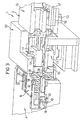
- Figure 3 shows a perspective view of the connection arrangement from Figure 1 in the unplugged state, the Components of the connection arrangement partially cut are shown
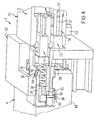
- Figure 4 shows the connection arrangement from Figure 3 in locked state
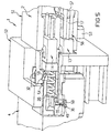
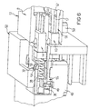
- Figure 5, Figure 6, Figure 7 and Figure 8 show the connection arrangement from Figure 3 in different positions between a released and a locked state.
- FIG. 1 shows a connection arrangement 1 according to the invention exploded perspective view.
- the connection arrangement 1 is divided into a bushing housing 2, which is arranged on a carrier plate 3, in a Board housing 4, which is arranged on a circuit board 5, as well as in a first ferrule container 6 and in one second ferrule container 7.
- the connection arrangement 1 serves for connecting a first multiple optical waveguide 11 with a second multiple optical waveguide 11 'and one third multiple optical fiber 12 with a fourth Multiple optical fibers 12 ', each by only one Line of symmetry are shown.
- the first ferrule container 6 is designed so that it first multiple optical fiber 11 and the third Multiple optical fiber 12 can accommodate.
- first multiple optical fiber 11 and the third Multiple optical fiber 12 are the single fibers at the end of the first multiple optical fiber 11 and at the end of the third multiple optical fiber 12 side by side in a first ferrule 13 and recorded in a second ferrule 14 such that the ends of the individual fibers with a first end face 15 of the first ferrule 13 or with a second end face 16 of the second ferrule 14 flush to lock.
- the first ferrule 13 has two guide pins 17 and wherein the second ferrule 14 also has two guide pins 17 having. Only one of the four is in the drawing Guide pins 17 designated by a reference number.
- the emerging ends of the individual fibers of the first multiple optical waveguide 11 and the third multiple optical fiber 12 are only thin in the drawing Points indicated that are located within the first ferrule 13 and within the second ferrule 14 between each Extend guide pins 17.
- the first ferrule 13 and the second ferrule 14 have in Cross section transverse to the extension of the first multiple optical waveguide 11 and the third multiple optical fiber 12 each have a rectangular cross section.
- the second Multiple optical fiber 11 'and the fourth multiple optical fiber 12 ' also have ferrules that but are not shown in this view.
- the first ferrule container 6 is used to hold the first Ferrule 13 and the second ferrule 14.
- the first Ferrule container 6 has a substantially cuboid shape External shape and has a lower ferrule shaft inside 20 and an upper ferrule shaft 21 as best can be seen in Figure 2.
- the lower ferrule shaft 20 and the upper ferrule shaft 21 extend one above the other in the longitudinal direction of the first ferrule container 6.
- the lower ferrule shaft 20 has a lower ferrule outlet opening 22, while the upper ferrule shaft 21 has an upper ferrule outlet opening 23.
- the function of the detent opening 25 is in connection with a spring holder 26 shown in Figure 1 can be seen.
- the spring holder 26 With an end face 27 each a compression spring 28 in the direction of the outlet openings 21 and 22.
- To fix the spring holder 26 in the first Ferrule containers 6 are two starting from the End face 27 legs 29 extending rearward in a U-shape provided that outward to the boundary wall of the first ferrule container 6 protruding spring holder locking lugs Have 30, of which only an upper in Figure 1 Spring holder latch 30 can be seen.
- the first shows Total ferrule container 6 on its longer outer edges four spring tongues 31, which extend in the longitudinal direction of the Ferrule containers 6 extend and their ends transverse to the Longitudinal directions of the ferrule container 6 are movable.
- snap hooks 32 are provided at the ends of the spring tongues 31, each one to the rear to the detent opening 25 have directed locking edge 33.
- the snap hooks 32 taper towards the front Exit openings 22 and 23 out.
- the snap hooks 32 are designed so that in the idle state shown in FIG is shown, with its outer edges over the outer Surfaces of the lateral boundary surfaces of the first Protruding ferrule containers 6. They are still like this formed that when the snap hook 32 transverse to the longitudinal direction of the first ferrule container 6 Spring tongue 31 yields, so that the snap hook 32 in one Edge opening 34 of the first ferrule container 6 engages.
- the first ferrule container 6 also has one lateral spring tongue 35 with a lateral snap hook 36 on.
- the side snap hook 36 has on its rear End of a side locking edge 37 and runs towards the front tapering.
- the side snap hook 36 protrudes the outer surface of a side boundary wall 38 of the first ferrule container 6 and can be under one of these acting force in one in the side Delimiting wall 38 provided lateral opening 39 be pushed in.
- the snap hooks have the same geometries and Dimensions, however, are on opposite sides appropriate.
- the second ferrule container 7 corresponds essentially to that first ferrule container 6. As shown in the illustration in Figure 2 sees best, the second ferrule container 7th but no lower or upper ferrule shaft, rather, a left ferrule shaft 40 and one right ferrule shaft 41.
- the left ferrule shaft 40 and the right ferrule shaft 41 correspond in terms of Dimensions of the lower ferrule shaft 20 and the upper Ferrule shaft 21, but they are in terms of their Alignment with the longitudinal axis of the second Ferrule container 7 by 90 ° with respect to the orientation of the lower ferrule shaft 20 and the upper ferrule shaft 21 rotated.
- the same components are the same Ferrule container 7 given the same reference numerals as the first ferrule container 6.
- the second one Ferrule container 7 has a lateral boundary wall 38, one side spring tongue with one side Snap hook and a side locking edge which the lateral spring tongue 35, the lateral snap hook 36 and the lateral locking edge 37 of the first ferrule container 6 in terms of location and orientation and dimensions correspond identically.
- the upper boundary wall 24 of the second ferrule container 7 has none Latch opening. This latch opening of the second Rather, ferrule container 7 is located on one corresponding position in the lateral boundary wall 38 as well as in the other boundary wall opposite of the second ferrule container 7. Because of the special Arrangement of the lateral spring tongues 35 in the first Ferrule container 6 and 7 in the second ferrule container whose orientation-based coding causes.
- the on-board housing 4 can best be seen in FIG. 1.
- the On-board housing 4 is an essentially cuboid housing formed the one upper wall 42 and two to each other has symmetrical side walls 43. At the bottom of one bottom wall 44 four plug pins 45 are formed with which the on-board housing 4 in corresponding openings in the Printed circuit board 5 is firmly pressed.
- the end walls of the Board housing 4 are open on both sides, the inside the on-board housing 4 and from the walls 42, 43 and 44 enclosed cavity by a central wall 46 into a first through channel 47 and into a second Through channel 48 is divided.
- the first through channel 47 and the second through channel 48 are of dimensions ago held so that the first ferrule container 6 in the first Through channel 47 is receivable, while the second Ferrule container 7 can be accommodated in the second through channel 48 is.
- lateral locking lug openings 49 provided, of which in the view in Figure 1 only lateral detent opening 49 of the first through-channel 47 you can see.
- the lateral locking lug openings 49 are designed such that them with the first and second state in place Ferrule containers 6 and 7 with the side snap hooks 36 work together.
- the on-board housing ejector structure 50 designed so that when inserted State of the first and second ferrule containers 6, 7 in the first through channel 47 and into the second through channel 48 cooperates with the snap hooks 32 located above.
- the bushing housing 2 is divided into a ferrule area 51 and in a board receiving area 52, each seen as a cuboid outer shape of different sizes.
- the ferrule area 51 for receiving the second multiple optical waveguide 11 'and the third multiple optical waveguide 12' is, in cross section transverse to the course of the multiple optical fibers 11 'and 12' kept smaller than the board receiving area 52.
- the carrier plate 3 has a substantially rectangular opening on, the outline of which essentially corresponds to the external dimensions of the Ferrule area 51 coincides. This is the passage of the ferrule region 51 through the carrier plate 3 guaranteed.
- this shows Feed-through housing 2 on the inside feed-through locking lugs 54 and three feed-through ejector structures 55 on, from which can only be seen in FIG. 3 because the symmetrically opposite other feed-through ejector structure is covered by other components. Between these outside lead-through ejector structures 55 there is still a central bushing ejector structure that for releasing the "inside" snap hooks Ferrule container ensures.
- the bushing locking lugs 54 act with appropriate snap hooks on the edges of the Ferrule containers 6, 7 together while the feed-through ejector structure 55 on the side snap hooks 36 of the Ferrule container 6, 7 acts.
- FIG. 3 In the illustration in figure 3 is a third ferrule 56 in the ferrule region 51 shown inserted, the third ferrule 56 also cut longitudinally in the area of a guide bore 57 is shown.
- the guide bore 57 takes when assembled State of the third ferrule 56 with the first Ferrule 13 has a guide pin 17 so that the front ends the third ferrule 56 and the first ferrule 13 exactly to each other are positioned, which results in a low insertion loss the optical connection of the individual fibers of the optical fibers 11 and 11 'guaranteed.
- FIG 3 shows the assembled system of the connection arrangement 1 from Figure 1 in a still unplugged state. There cuts have been introduced to illustrate the processes can.
- the ferrule container 6 is in this state with the side snap hooks 36 in the side Locking nose openings 49 of the board housing 4 locked.
- Feed-through ejector structures 55 straight in this state on the side snap hooks 36 of the ferrule container 6 on.
- the board housing ejector structures 50 lie in this State just on the snap hooks 32 of the ferrule container 6, 7, which, however, cannot be seen in FIG. 4.
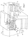
- FIG. 7 shows the case of a maximum further movement of the Board housing 4 in the direction of the bushing 2.
- the board housing 4 moves together with the circuit board 5 in a direction from Feed-through housing 2 away.
- the board housing ejector structures occur with in the area of the snap hooks 32 provided starting paragraphs 58 in contact so that the Snap hook 32 while bending the spring clip 31 inwards can be pressed, as best seen in Figure 8. As a result, the snap hooks 32 detach from the lead-through latches 54.
- the side snap hooks 36 lie with one forward section 59 on a corresponding wall the side locking lug opening 49, which prevents the ferrule container 6 when pulling out the board housing 4 from the bushing housing 2 in the bushing housing 2 remains. Rather, when pulling out the board case 4 in the state shown in Figure 8 due to the Interaction of paragraph 59 with the lateral Latch opening 49 of the ferrule container 6 with the Board housing 4 moved. After pulling out the Board housing 4 from the bushing 2 is located the connection arrangement 1 again in that shown in Figure 3 Status.
- connection arrangement 1 Another advantage of the connection arrangement 1 is in that the position of the ferrules 13, 14 and 56 after Lock regardless of the position of the circuit board 5 is held to each other with respect to the support plate 3. On in this way, the compression springs 28 Tolerance distance to be compensated to a defined maximum value set.
- connection arrangement 1 can be used achieve high packing densities.
Description
Die Erfindung betrifft einen Ferrulencontainer zur Aufnahme
einer in einer Ferrule angeordneten optischen Mehrfachfaser.
Die Erfindung betrifft weiterhin eine Verbindungsanordnung
zum Verbinden von optischen Mehrfachfasern.The invention relates to a ferrule container for receiving an optical multiple fiber arranged in a ferrule.
The invention further relates to a connection arrangement for connecting optical multiple fibers.
In der modernen Daten- und Telekommunikation werden zunehmend
steigende Datenraten und Übertragungsbandbreiten realisiert.
Hierbei sind heute schon die Grenzen der Leistungsfähigkeit
rein elektronischer Systeme erreicht worden. Um die in
Zukunft benötigten Datenraten bewältigen zu können, wird
vermehrt mit optischen Übertragungssystemen gearbeitet.
Bisher waren für diese Systeme Einzelfaserverbindungen der
vorherrschende Lösungsansatz, da die verwendeten Laser bisher
nur als Einzelkomponenten hergestellt werden konnten. Mit
modernen Lasern können kostengünstig sogenannte Laser-Arrays
hergestellt und getestet werden, so daß eine zunehmende
Verlagerung der optischen Übertragungssysteme von einer
seriellen Übertragung auf eine parallele Übertragung erfolgt.In modern data and telecommunications, increasing data rates and transmission bandwidths are increasingly being realized.
The limits of the performance of purely electronic systems have already been reached today. In order to be able to cope with the data rates required in the future, optical transmission systems are increasingly used.
So far, single fiber connections have been the predominant solution for these systems, since the lasers used could previously only be manufactured as individual components. So-called laser arrays can be produced and tested inexpensively with modern lasers, so that an increasing shift of the optical transmission systems from a serial transmission to a parallel transmission takes place.
Bei den bestehenden Ferrulencontainern und Verbindungsanordnungen zum Verbinden von optischen Mehrfachfasern ist von Nachteil, daß mit diesen nur eine geringe Packungsdichte erreicht werden kann (siehe z.B. EP 0 696 748A, EP 0 718 652A, WO 86/02740). Darüber hinaus können in die bestehenden Verbindungsanordnungen keine elektrischen Verbindersysteme integriert werden. Schließlich ist die Flexibilität der vorhandenen Verbindungsanordnungen begrenzt, was aufwendige Gestaltungen notwendig macht, um einen gleichzeitigen Anschluß von mit unterschiedlichen Orientierungen ankommenden Lichtwellenleitern zu ermöglichen.With the existing ferrule containers and connection arrangements for connecting multiple optical fibers is from Disadvantage that with these only a low packing density can be achieved (see e.g. EP 0 696 748A, EP 0 718 652A, WO 86/02740). In addition, in the existing connection arrangements no electrical Connector systems are integrated. After all, that is Limited flexibility of the existing connection arrangements, which requires elaborate designs to simultaneous connection of different To enable orientations incoming fiber optics.
Es ist daher Aufgabe der Erfindung, einen Ferrulencontainer sowie eine Verbindungsanordnung zum Verbinden von optischen Mehrfachfasern bereitzustellen, mit dem eine hohe Packungsdichte erreicht werden kann. Weiterhin soll eine hohe Flexibilität erreicht werden, wobei möglichst optische und elektrische Verbindungen in einem System bereitgestellt werden sollen. Weiterhin soll eine einfache Verbindung von optischen Mehrfachfasern gewährleistet sein, wobei die engen Toleranzen für optische Verbindungen eingehalten werden sollen.It is therefore an object of the invention to provide a ferrule container and a connection arrangement for connecting optical To provide multiple fibers with a high Packing density can be achieved. Furthermore, a high Flexibility can be achieved, with the greatest possible visual and electrical connections provided in a system should be. Furthermore, a simple connection of optical multiple fibers can be guaranteed, the narrow Tolerances for optical connections are observed should.
Schließlich ist es noch Aufgabe der Erfindung, eine Verbindungsanordnung bereitzustellen, die insbesondere für modulartig aufgebaute elektronische Geräte mit mehreren, im wesentlichen parallel ausgerichteten Leiterplatteneinschüben verwendet kann, die von einer gemeinsamen Trägerplatine oder einer sogenannten Backplane-Platine getragen werden und über diese untereinander und nach außen hin optisch und gegebenenfalls auch elektrisch verbindbar sind.Finally, it is still an object of the invention, a To provide connection arrangement, which is particularly for modular electronic devices with several, in essentially parallel PCB slots can be used by a common carrier board or a so-called backplane board can be worn and over these visually and with each other and to the outside are optionally also electrically connectable.
Gemäß der Erfindung wird dies mit einem Ferrulencontainer
gemäß Anspruch 1 und mit einer Verbindungsanordnung gemäß Anspruch 12 gelöst. Der Ferrulencontainer ist so ausgebildet,
daß mehrere jeweils in Ferrulen angeordnete
optische Fasern aufnehmbar sind. Durch diese Gestaltung läßt
sich eine hohe Packungsdichte erreichen, da zur Verbindung
mehrerer optischer Mehrfachfasern bereits ein einziger
Ferrulencontainer ausreicht. Vorteilhafterweise sind sowohl
Ferrulen mit Mehrfachfasern als auch Ferrulen mit
Einfachfasern zusammen in dem erfindungsgemäßen
Ferrulencontainer aufnehmbar. Schließlich ist es ferner auch
denkbar sowohl optische als auch elektrische Verbindungen
zusammen in einem Ferrulencontainer unterzubringen.According to the invention, this is done with a ferrule container
solved according to claim 1 and with a connection arrangement according to
Dabei weist der erfindungsgemäße Ferrulencontainer vorteilhafterweise sich zueinander parallel erstreckende Ferrulenschächte zur Aufnahme der Ferrulen auf, wobei die Ferrulenschächte wenigstens je eine insbesondere betätigbare Ferrulen-Halteeinrichtung zur Fixierung der Ferrulen aufweisen.The ferrule container according to the invention advantageously has Ferrule shafts extending parallel to one another to accommodate the ferrules, the Ferrule shafts each have at least one that can be actuated Ferrule holding device for fixing the ferrules exhibit.
Die Ferrulen-Halteeinrichtung gliedert sich in einen in einem Ferrulenschacht aufnehmbaren Federhalter, in eine Druckfeder sowie in im Aufnahmeschacht vorgesehene Federhalter-Rastnasen, wobei die Federhalter-Rastnasen vorteilhafterweise betätigbar ausgebildet sind. Mit einer solchen Ferrulen-Halteeinrichtung läßt sich eine Ferrule besonders einfach im Ferrulencontainer befestigen, wobei durch das Vorsehen einer auf die Ferrule einwirkenden Druckfeder ein Spielausgleich gewährleistet ist. Die Druckfeder ist nämlich so zwischen der Ferrule und dem Federhalter angeordnet, daß die Ferrule durch die Druckfeder an einen Anschlag im Ferrulenschacht gedrückt wird. Kommt das freie Stirnende der Ferrule mit dem freien Stirnende der optischen Mehrfachfasern einer weiteren Ferrule in Kontakt, kann die Ferrule gegen die Verformung der Druckfeder nach hinten in den Ferrulencontainer ausweichen und auf diese Weise Lageungenauigkeiten ausgleichen.The ferrule holding device is divided into one Ferrule shaft mountable spring holder, in a compression spring as well as in spring retainer lugs provided in the receiving shaft, the spring holder locking lugs advantageously are designed to be actuated. With such a ferrule holding device a ferrule is particularly easy to use Fasten the ferrule container, by providing a a play compensation on the compression spring acting on the ferrule is guaranteed. The compression spring is so between the Ferrule and the spring holder arranged that the ferrule through the compression spring is pressed against a stop in the ferrule shaft becomes. The free front end of the ferrule comes with the free one Front end of the optical multiple fibers of another ferrule in contact, the ferrule can prevent the deformation of the Dodge the compression spring back into the ferrule container and compensate for positional inaccuracies in this way.
Wenn die Federhalter-Rastnasen betätigbar ausgebildet sind, dann kann die Ferrule auf einfache Weise aus dem Ferrulencontainer entnommen werden. Auf der anderen Seite ist es mit dem so ausgebildeten Ferrulencontainer auf einfache Weise möglich, eine Ferrule im Ferrulencontainer zu montieren. If the spring holder locking lugs are designed to be actuatable, then the ferrule can be easily removed from the ferrule container be removed. On the other hand, it is with the ferrule container designed in this way in a simple manner possible to mount a ferrule in the ferrule container.
Besonders vorteilhaft ist es, wenn der Ferrulencontainer außenseitig Verriegelungselemente aufweist, die so ausgebildet sind, daß der Ferrulencontainer in einem Boardgehäuse oder in einem Verbindungsgehäuse insbesondere lösbar fixierbar ist. Dadurch kann eine feste Verbindung zwischen dem Ferrulencontainer und einem Boardgehäuse oder einem Verbindungsgehäuse erzielt werden. Gerade bei dem Vorsehen eines Verbindungsgehäuses lassen sich so schnell lösbare und zuverlässige Verbindungen zwischen optischen Mehrfachfasern mit einer überaus hohen Packungsdichte erreichen.It is particularly advantageous if the ferrule container has locking elements on the outside, so are designed so that the ferrule container in one Board housing or in a connection housing in particular is releasably fixable. This can create a firm connection between the ferrule container and a board housing or a connection housing can be achieved. Especially with that Providing a junction box can be done so quickly detachable and reliable connections between optical Multiple fibers with an extremely high packing density to reach.
Wenn mehrere Ferrulenschächte vorgesehen sind, die im Querschnitt eine rechteckige Innenform haben, wobei vorzugsweise je zwei Ferrulenschächte so angeordnet sind, daß sie im Querschnitt einer ihrer längeren Innenkanten unmittelbar nebeneinander zu liegen kommen, dann ergibt sich ein Ferrulencontainer mit einer besonders hohen Packungsdichte. Dabei hat der Ferrulencontainer im Querschnitt eine im wesentlichen quadratische Außenform. Dadurch läßt sich eine standardisierte Ausführung des erfindungsgemäßen Ferrulencontainers erreichen, so daß sich baukastenartige Verbindungsanordnungen auf einfache Weise zusammenstellen lassen.If several ferrule shafts are provided, the cross section have a rectangular inner shape, preferably two ferrule shafts are arranged so that they are in cross section one of their longer inner edges right next to each other come to rest, then there is a ferrule container with a particularly high packing density. Doing the ferrule container in cross-section essentially one square outer shape. This allows a standardized Execution of the ferrule container according to the invention achieve so that there are modular connection arrangements can be put together easily.
Gerade bei einem Ferrulencontainer mit einem im wesentlichen quadratischen Querschnitt ist es von Vorteil, wenn außenseitig am Ferrulencontainer Ferrulencontainer-Kodierelemente vorgesehen sind, die so ausgebildet sind, daß mit ihnen eine Einschuborientierung des Ferrulencontainers in einem Boardgehäuse oder in einem Verbindungsgehäuse festlegbar ist. Dadurch lassen sich Montagefehler von vornherein auf einfache Weise vermeiden, wenn bereits bei der Auslegung einer Verbindungsanordnung die richtige Orientierung festgelegt wird.Especially with a ferrule container with one square cross section, it is advantageous if Ferrule container coding elements on the outside of the ferrule container are provided, which are designed so that with them an insertion orientation of the ferrule container in in a board housing or in a connection housing is definable. This allows assembly errors from Avoid in a simple way beforehand, if already at the Designing a connection arrangement the right one Orientation is determined.
Abweichend davon oder zusätzlich zu der vorstehenden Ausbildung kann der Ferrulencontainer im Querschnitt auch eine rechteckige Außenform haben. Dadurch bleiben von insgesamt vier möglichen Positionen des Ferrulencontainers in einem Verbindungselement nur noch zwei Orientierungen übrig, so daß sich eine besonders einfache Kodierung ergibt.Notwithstanding this or in addition to the above The ferrule container can also be trained in cross-section have a rectangular outer shape. This will keep from a total of four possible positions of the ferrule container in there are only two orientations left for a connecting element, so that a particularly simple coding results.
Im übrigen ist es auch möglich, den Ferrulencontainer auf der Boardseite, auf der Seite des Kabelsteckers und/oder insbesondere auch auf der Seite des - soweit vorhanden-Federhalters durch Vorsehen entsprechender Kodierelemente richtungsmäßig zu kodieren.Otherwise, it is also possible to place the ferrule container on the Board side, on the side of the cable connector and / or especially on the side of the - if available - spring holder by providing appropriate coding elements to encode directionally.
Schließlich ist noch vorgesehen, daß im Bereich des Einschubschachts bzw. der Einschubschächte und/oder im Bereich der Außenseite des Ferrulencontainers eine Abschirmung gegen elektromagnetische Einflüsse vorgesehen ist. Gerade bei kombiniertem Vorsehen von elektrischen und optischen Verbindungen wird hierbei für die elektrischen Verbindungen eine zuverlässige Abschirmung und ein störungsfreier Betrieb des Ferrulencontainers gewährleistet.Finally, it is provided that in the area of the slot or the insertion slots and / or in the area a shield against the outside of the ferrule container electromagnetic influences is provided. Especially with combined provision of electrical and optical connections becomes a for the electrical connections reliable shielding and trouble-free operation of the Ferrule containers guaranteed.
Schließlich weist der erfindungsgemäße Ferrulencontainer im Bereich einer Stirnseite wenigsten eine Führungsbohrung auf, in die ein Führungsstift einsetzbar ist. Auf diese Weise können mehrere Ferrulen über ein einziges Führungsstift/Führungsbohrungspaar zueinander ausgerichtet werden.Finally, the ferrule container according to the invention in Area of one end face at least one guide hole, in which a guide pin can be inserted. In this way can have multiple ferrules through a single guide pin / guide hole pair aligned with each other.
Bei einer besonderen Ausführung können bis zu zwei Mehrfaserferrulen in einen Ferrulencontainer eingebaut werden. Dabei ist es besonders vorteilhaft, daß für ein einwandfreies Funktionieren einer Verbindungsanordnung mit zwei aneinander zu koppelnden Ferrulen jeweils nur ein Ferrulenschacht der dafür notwendigen zwei Ferrulencontainer bestückt sein muß. Auf diese Weise wird eine maximale Packungsdichte der Lichtwellenleiter mit einer maximalen Flexibilität hinsichtlich der Verwendung der erfindungsgemäßen Ferrulencontainer kombiniert.In a special version, up to two Multi-fiber ferrules built into a ferrule container become. It is particularly advantageous that for a proper functioning of a connection arrangement with two ferrules to be coupled to each other only one Ferrule shaft of the two ferrule containers required for this must be equipped. This way a maximum Packing density of the optical fibers with a maximum Flexibility in using the ferrule container according to the invention combined.
Die Aufgabe der Erfindung wird weiterhin durch eine Verbindungsanordnung zum Verbinden von optischen Mehrfachfasern gelöst, die die folgenden Merkmale aufweist:
- wenigstens einen ersten Ferrulencontainer zur Aufnahme wenigstens einer in einer ersten Ferrule angeordneten ersten optischen Mehrfachfaser,
- wenigstens ein insbesondere auf einer Platine anbringbares Boardgehäuse zur Aufnahme des ersten Ferrulencontainers,
- wenigsten ein insbesondere an einer Backplane anbringbares Duchführungsgehäuse zur Aufnahme wenigstens einer in einer zweiten Ferrule angeordneten zweiten optischen Mehrfachfaser,
- at least one first ferrule container for receiving at least one first optical multiple fiber arranged in a first ferrule,
- at least one board housing, which can be attached in particular to a circuit board, for receiving the first ferrule container,
- at least one lead-through housing, which can be attached in particular to a backplane, for accommodating at least one second optical multiple fiber arranged in a second ferrule,
Mit dieser Verbindungsanordnung läßt sich eine hohe Packungsdichte bei gleichzeitig großem Toleranzspielraum erzeugen. Dies ist besonders bei Anwendungsfällen wichtig, bei denen in einem modulartig aufgebauten Gerät mit mehreren Leiterplatteneinschüben und einer gemeinsamen Trägerplatte für die Leiterplatteneinschübe die Leiterplatten untereinander und nach außen hin optisch und gegebenenfalls auch elektrisch verbindbar sein müssen. Der Fachmann bezeichnet die Ebene der Trägerplatte der einzelnen Leiterplatten als "Backplane", während die Ebene eines Leiterplatteneinschubs als "Board" bezeichnet wird. Die Erfindung beruht dabei auf der erfindungswesendlichen Erkenntnis, daß eine Auftrennung der Verbindungsanordnung in die Bestandteile "Ferrulencontainer", "Boardgehäuse" und in das im Bereich der Backplaneebene angebrachte "Durchführungsgehäuse" für einen solchen Toleranzausgleich von großer Bedeutung ist. Durch eine solche Auftrennung der Einzelteile läßt sich nämlich erreichen, daß während des Transports eines Leiterplatteneinschubs eine feste Verbindung zwischen einem Ferrulencontainer und der Leiterplatte besteht, indem der Ferrulencontainer mit dem Boardgehäuse in Verbindung steht. Beim Einbringen des Leiterplatteneinschubs auf die Trägerplatte mit dem auf dieser vorgesehenen Durchführungsgehäuse kann dann eine feste Verbindung zwischen dem Ferrulencontainer und dem Duchführungsgehäuse erzeugt werden, während die Verbindung zwischen Ferrulencontainer und Boardgehäuse aufgehoben wird. Dadurch kann sich die Leiterplatte in großem Maße bezüglich der Trägerplatte verlagern, ohne daß dies negative, Auswirkung auf eine Verbindung zwischen einer Ferrule auf der Boardseite und einer gegenseitigen Ferrule hat.With this connection arrangement, a high Packing density with a large margin of tolerance produce. This is especially important for use cases where in a modular device with several PCB slots and a common carrier plate for the printed circuit boards with each other and externally visually and if necessary must also be electrically connectable. The expert denotes the level of the carrier plate of the individual Printed circuit boards as a "backplane" while the level of a PCB slots is referred to as a "board". The Invention is based on the essential to the invention Recognition that a separation of the connection arrangement in the components "ferrule container", "board housing" and in that attached in the area of the backplane level "Feed-through housing" for such tolerance compensation is of great importance. By such a separation of the Items can be achieved that during the Transport of a PCB insert a firm connection between a ferrule container and the circuit board consists of the ferrule container with the board housing in Connection is established. When inserting the PCB insert onto the carrier plate with that provided on it Bushing housing can then have a firm connection between the ferrule container and the lead-through housing be while the connection between ferrule container and Board housing is lifted. As a result, the PCB to a large extent with respect to the carrier board relocate without this having a negative impact on a Connection between a ferrule on the board side and a mutual ferrule.
Abweichend von der vorstehend ausgeführten Anwendung kann die erfindungsgemäße Verbindungsanordnung auch zur zuverlässigen und dennoch schnell lösbaren fliegenden Verbindung von Mehrfach-Lichtwellenleitern verwendet werden. Durch die Auftrennung der Verbindungsanordnung in Ferrulencontainer, Boardgehäuse und Durchführungsgehäuse können auf einfache Weise betätigbare lösbare Verbindungsanordnungen erzeugt werden. Hierzu ist insbesondere vorgesehen, daß die Verbindung zwischen einem in einem Boardgehäuse angeordneten Ferrulencontainer und einem in dem Durchgangsgehäuse angeordneten Ferrulencontainer dadurch hergestellt und wieder aufgelöst wird, daß das Boardgehäuse innerhalb des Durchführungsgehäuses bewegt wird, um die beiden Ferrulencontainer miteinander zu verriegeln.Deviating from the application outlined above, the Connection arrangement according to the invention also for reliable and yet quickly releasable flying connection from Multiple optical fibers can be used. Through the Separation of the connection arrangement into ferrule containers, Board cases and bushings can be easily Generated actuatable releasable connection assemblies become. For this purpose, it is particularly provided that the Connection between one arranged in a board housing Ferrule container and one in the passage housing arranged ferrule container manufactured thereby and again resolved that the board housing within the Bushing is moved to the two Lock ferrule containers together.
Vorteilhafterweise ist bei der erfindungsgemäßen Verbindungsanordnung eine lösbare erste Verriegelungseinrichtung zur insbesondere kraftschlüssigen Verbindung von erstem Ferrulencontainer und Boardgehäuse sowie eine lösbare zweite Verriegelungseinrichtung zur insbesondere kraftschlüssigen Verbindung von erstem Ferrulencontainer und Durchführungsgehäuse vorgesehen. "Lösbar" bedeutet hierbei, daß zwischen einem verriegelten und einem gelösten Zustand des ersten Ferrulencontainers in dem Boardgehäuse bzw. in dem Durchführungsgehäuse hin- und hergeschaltet werden kann. Bei einem verriegelten Zustand ergibt sich eine im wesentlichen feste Verbindung zwischen Ferrulencontainer und Boardgehäuse bzw. Durchführungsgehäuse, während sich bei einem gelösten Zustand der Verriegelungseinrichtung der Ferrulencontainer innerhalb des Boardgehäuses bzw. innerhalb des Durchführungsgehäuses im wesentlichen frei bewegen kann.The connection arrangement according to the invention is advantageous a releasable first locking device for in particular non-positive connection of the first ferrule container and board case as well as a detachable second Locking device for in particular non-positive Connection of the first ferrule container and Feed-through housing provided. "Solvable" here means that between a locked and a released state of the first ferrule container in the board housing or in the Bushing housing can be switched back and forth. At a locked state essentially results in one fixed connection between ferrule container and board housing or bushing housing, while one is detached Condition of the locking device of the ferrule containers inside the board housing or inside the Bushing can move essentially freely.
Bei der erfindungsgemäßen Verbindungsanordnung befindet sich im zusammengesteckten Zustand von Boardgehäuse und Durchführungsgehäuse die erste Verriegelungseinrichtung in gelöstem Zustand und die zweite Verriegelungseinrichtung in gesperrtem Zustand, während sich in voneinander getrenntem Zustand von Boardgehäuse und Durchführungsgehäuse die erste Verriegelungseinrichtung in gesperrtem Zustand befindet. In voneinander getrenntem Zustand von Boardgehäuse und Durchführungsgehäuse tritt die zweite Verriegelungseinrichtung nicht in Aktion.In the connection arrangement according to the invention there is when the board housing and Bushing the first locking device in released state and the second locking device in locked state while in separate Condition of board housing and bushing housing the first Locking device is in the locked state. In separate state of board housing and Grommet housing occurs the second Locking device not in action.
Dabei ist vorteilhafterweise die erste Verriegelungseinrichtung so ausgebildet, daß sie durch einen Bewegung des Boardgehäuses in Richtung weg vom Durchführungsgehäuse von einem gelösten Zustand in einen gesperrten Zustand bringbar ist, wobei dies insbesondere auch automatisch im Zuge der Bewegung des Boardgehäuses erfolgen kann. Bei einer Bewegung des Boardgehäuses in Richtung zum Durchführungsgehäuse hin dagegen ist die erste Verriegelungseinrichtung vorteilhafterweise in einen gelösten Zustand bringbar, wobei auch dies automatisch alleine aufgrund der Bewegung des Boardgehäuses in Richtung zum Durchführungsgehäuse hin erfolgen kann. Durch diese Ausgestaltungen ist gewährleistet, daß sich die erste Verriegelungseinrichtung in getrenntem Zustand von Boardgehäuse und Durchführungsgehäuse in gesperrtem Zustand befindet, während bei zusammengestecktem Zustand von Boardgehäuse und Durchführungsgehäuse die erste Verriegelungseinrichtung in gelöstem Zustand befindlich ist.The first locking device is advantageous trained so that by movement of the Board housing in the direction away from the bushing housing from can be brought into a locked state from a released state is, which is also automatically in the course of Movement of the board housing can take place. With a movement of the board housing in the direction of the bushing housing against it is the first locking device can advantageously be brought into a released state, wherein also this automatically due to the movement of the Board housing towards the bushing housing can be done. These configurations ensure that the first locking device in separate Condition of board housing and bushing housing in locked state while while plugged together Condition of board housing and bushing housing the first Locking device is in the released state.
Was die zweite Verriegelungseinrichtung betrifft, so ist diese vorzugsweise so ausgebildet, daß sie durch eine Bewegung des Boardgehäuses in Richtung zum Durchführungsgehäuse hin in einen gesperrten Zustand bringbar ist, und so, daß sie eine feste Verbindung zwischen erstem Ferrulencontainer und Duchführungsgehäuse erzeugt. Dabei ist vorgesehen, daß die zweite Verriegelungseinrichtung automatisch in einen gesperrten Zustand übergeht, wenn das Boardgehäuse in Richtung zum Durchführungsgehäuse hin bewegt wird. Demgegenüber wird die zweite Verriegelungseinrichtung bei einer Bewegung des Boardgehäuses in Richtung vom Durchführungsgehäuse weg in einen gelösten Zustand gebracht. Die vorstehenden Betätigungen der zweiten Verriegelungseinrichtung sind dabei insbesondere so vorgesehen, daß sie bei einer Bewegung des Boardgehäuses automatisch erfolgen.As for the second locking device, it is these are preferably designed so that they are replaced by a Movement of the board housing towards Feed-through housing can be brought into a locked state and so that it is a firm connection between the first Ferrule container and lead-through housing created. It is provided that the second locking device automatically goes into a locked state when that Board housing moved towards the bushing housing becomes. In contrast, the second locking device when the board housing moves in the direction of Bushing housing removed in a released state. The above operations of the second locking device are particularly provided so that automatically when the board housing moves respectively.
Zum Verrasten der ersten Verriegelungseinrichtung sind im Bereich des Ferrulencontainers Schnapphaken sowie im Bereich des Boardgehäuses Boardgehäuse-Rastnasen vorgesehen. Weiterhin kann die erste Verriegelungseinrichtung im Bereich des Durchführungsgehäuses vorgesehene erste Auswerfernasen aufweisen. Dadurch wird eine automatisierte Betätigung bzw. ein automatisiertes Lösen der ersten Verriegelungseinrichtung begünstigt.To lock the first locking device in Area of the snap hook ferrule container as well as in the area of the board housing board housing locking lugs provided. Furthermore, the first locking device in the area of the lead-through housing provided first ejector lugs exhibit. This enables automated actuation or an automated release of the first locking device favored.
Ebenso kann die zweite Verriegelungseinrichtung im Bereich des Ferrulencontainers vorgesehene Schnapphaken sowie seitens des Durchführungsgehäuses vorgesehene Duchführungsgehäuse-Rastnasen aufweisen, wobei zum Lösen der zweiten Verriegelungsvorrichtung auch im Bereich des Durchführungsgehäuses zweite Auswerfernasen vorgesehen sein können.Likewise, the second locking device in the area of the ferrule container provided snap hooks as well as on the part of the lead-through housing provided with lead-through housing locking lugs have, wherein to solve the second Locking device also in the area of Bushing housing second ejector lugs may be provided can.
Durch die vorstehende Ausbildung ist eine automatisierte Betätigung der zweiten Verriegelungseinrichtung gewährleistet. Dabei ergibt sich eine besonders einfache Verbindungsanordnung dann, wenn die Schnapphaken der zweiten Verriegelungseinrichtung und die Anlaufabsätze durch dieselben Strukturen gebildet sind. The above training is automated Actuation of the second locking device guaranteed. This results in a particularly simple one Connection arrangement when the snap hooks of the second Locking device and the starting paragraphs through the same structures are formed.
Die hier beschriebene Erfindung ermöglicht den Aufbau eines optischen Verbindersystems mit einer sehr hohen Packungsdichte. Dabei ist es möglich, die Erfindung sowohl als alleinstehende Lösung auszuführen als auch die Erfindung in bereits bestehende elektrische Systeme zu integrieren. Die in elektrischen Verbindersystemen auftretenden Toleranzen werden so abgefangen, daß die für optische Verbindungen verpflichtenden Toleranzen eingehalten werden können. Zusätzlich bietet die Erfindung durch ihren modularen und symmetrischen Aufbau die Möglichkeit, alle in der Praxis auftretenden Anwendungsfälle abdecken zu können. Die erfindungsgemäße Lösung stellt eine Verbindungsanordnung bereit, die sowohl die großen axialen Toleranzen von mehreren Millimetern für elektrische Systeme als auch die geringen axialen Toleranzen von wenigen Mikrometern für optische Verbindungen zu gewährleisten in der Lage ist. Dadurch können sogar Durchbiegungen innerhalb der Backplane ausgeglichen werden, wobei eine überaus hohe Packungsdichte erreicht wird.The invention described here enables the construction of a optical connector system with a very high Packing density. It is possible to both the invention run as a stand-alone solution as well as the invention to integrate into existing electrical systems. The Tolerances occurring in electrical connector systems are intercepted so that the for optical connections obligatory tolerances can be met. In addition, the invention offers through its modular and symmetrical structure the possibility of all in practice to be able to cover occurring applications. The solution according to the invention provides a connection arrangement ready to meet both the large axial tolerances of several Millimeters for electrical systems as well as the small ones axial tolerances of a few micrometers for optical Is able to ensure connections. This allows even deflections within the backplane compensated be, whereby an extremely high packing density is achieved.
Die Erfindung ist in der Zeichnung anhand eines Ausführungsbeispiels näher beschrieben.The invention is in the drawing based on a Embodiment described in more detail.
Figur 1 zeigt eine explosionsartige perspektivische Darstellung einer erfindungsgemäßen Verbindungsanordnung mit zwei erfindunsgemäßen Ferrulencontainern,Figure 1 shows an exploded perspective Representation of a connection arrangement according to the invention two ferrule containers according to the invention,
Figur 2 zeigt eine perspektivische Darstellung der Ferrulencontainer aus Figur 1 in näherem Detail,Figure 2 shows a perspective view of the Ferrule container from Figure 1 in more detail,
Figur 3 zeigt eine perspektivische Darstellung der Verbindungsanordnung aus Figur 1 in ungestecktem Zustand, wobei die Bauteile der Verbindungsanordnung teilweise geschnitten dargestellt sind, Figure 3 shows a perspective view of the connection arrangement from Figure 1 in the unplugged state, the Components of the connection arrangement partially cut are shown
Figur 4 zeigt die Verbindungsanordung aus Figur 3 in verrastetem Zustand,Figure 4 shows the connection arrangement from Figure 3 in locked state,
Figur 5, Figur 6, Figur 7 und Figur 8 zeigen die Verbindungsanordnung aus Figur 3 in verschiedenen Stellungen zwischen einem gelösten und einem verrasteten Zustand.Figure 5, Figure 6, Figure 7 and Figure 8 show the connection arrangement from Figure 3 in different positions between a released and a locked state.
Figur 1 zeigt eine erfindungsgemäße Verbindungsanordnung 1 in
explosionsartiger perspektivischer Darstellung. Die Verbindungsanordung
1 gliedert sich in ein Durchführungsgehäuse 2,
das auf einer Trägerplatte 3 angeordnet ist, in ein
Boardgehäuse 4, das auf einer Leiterplatte 5 angeordnet ist,
sowie in- einen ersten Ferrulencontainer 6 und in einen
zweiten Ferrulencontainer 7. Die Verbindungsanordnung 1 dient
zum Verbinden eines ersten Mehrfach-Lichtwellenleiters 11 mit
einem zweiten Mehrfach-Lichtwellenleiter 11' sowie eines
dritten Mehrfach-Lichtwellenleiters 12 mit einem vierten
Mehrfach-Lichtwellenleiter 12', die jeweils nur durch eine
Symmetrielinie dargestellt sind.FIG. 1 shows a connection arrangement 1 according to the invention
exploded perspective view. The connection arrangement
1 is divided into a
Der erste Ferrulencontainer 6 ist so ausgebildet, daß er den
ersten Mehrfach-Lichtwellenleiter 11 und den dritten
Mehrfach-Lichtwellenleiter 12 aufnehmen kann. Dabei sind die
einzelnen Fasern am Ende des ersten Mehrfach-Lichtwellenleiters
11 und am Ende des dritten Mehrfach-Lichtwellenleiters
12 nebeneinander in einer ersten Ferrule
13 und in einer zweiten Ferrule 14 aufgenommen, und zwar
derart, daß die Stirnenden der einzelnen Fasern mit einem
ersten Stirnende 15 der ersten Ferrule 13 bzw. mit einem
zweiten Stirnende 16 der zweiten Ferrule 14 bündig
abschließen. Im ersten Stirnende 15 und im zweiten Stirnende
16 sind weiterhin Führungsstifte 17 vorgesehen, wobei die
erste Ferrule 13 zwei Führungsstifte 17 aufweist und wobei
die zweite Ferrule 14 ebenfalls zwei Führungsstifte 17
aufweist. In der Zeichnung ist nur einer der vier
Führungsstifte 17 mit einer Bezugsziffer bezeichnet. Die
austretenden Enden der Einzelfasern des ersten Mehrfach-Lichtwellenleiters
11 und des dritten Mehrfach-Lichtwellenleiters
12 sind in der Zeichnung nur als dünne
Punkte angedeutet, die sich innerhalb der ersten Ferrule 13
und innerhalb der zweiten Ferrule 14 jeweils zwischen den
Führungsstiften 17 erstrecken.The
Die erste Ferrule 13 und die zweite Ferrule 14 haben im
Querschnitt quer zur Erstreckung des ersten Mehrfach-Lichtwellenleiters
11 und des dritten Mehrfach-Lichtwellenleiters
12 jeweils einen rechteckigen Querschnitt. Der zweite
Mehrfach-Lichtwellenleiters 11' und der vierte Mehrfach-Lichtwellenleiter
12' weisen ebenfalls Ferrulen auf, die
jedoch in dieser Ansicht nicht dargestellt sind.The
Der erste Ferrulencontainer 6 dient zur Aufnahme der ersten
Ferrule 13 und der zweiten Ferrule 14. Der erste
Ferrulencontainer 6 hat eine im wesentlichen quaderförmige
Außenform und weist im Inneren einen unteren Ferrulenschacht
20 sowie einen oberen Ferrulenschacht 21 auf, wie am besten
in Figur 2 zu sehen ist. Der untere Ferrulenschacht 20 und
der obere Ferrulenschacht 21 erstrecken sich übereinanderliegend
in Längsrichtung des ersten Ferrulencontainers 6.
Dabei hat der untere Ferrulenschacht 20 eine untere Ferrulen-Austrittsöffnung
22, während der obere Ferrulenschacht 21
eine obere Ferrulen-Austrittsöffnung 23 aufweist. Bei
eingesetztem Zustand der ersten Ferrule 13 in den unteren
Ferrulenschacht 20 ragt das erste Stirnende 15 aus der
unteren Ferrulen-Austrittsöffnung 22, während bei
eingesetztem Zustand der zweiten Ferrule 14 in den oberen
Ferrulenschacht 21 das zweite Stirnende 16 aus der oberen
Ferrulen-Austrittsöffnung 23 ragt. Im Bereich einer oberen
Begrenzungswand 24 ist am von der oberen Ferrulen-Austrittsöffnung
23 abgewandten Ende des ersten Ferrulencontainers
6 eine Rastnasenöffnung 25 mit quadratischen Umriß
eingebracht. Eine ebensolche Rastnasenöffnung - in dieser
Darstellung nicht zu erkennen - befindet sich in der unteren
Begrenzungswand des unteren Ferrulenschachts 20, und zwar
genau gegenüberliegend von der Rastnasenöffnung 25.The
Die Funktion der Rastnasenöffnung 25 wird im Zusammenhang mit
einem in Figur 1 dargestellten Federhalter 26 ersichtlich.
Bei eingesetztem Zustand der ersten Ferrule 13 und der
zweiten Ferrule 14 in den ersten Ferrulencontainer 6 drückt
der Federhalter 26 diese mit einer Stirnfläche 27 über je
eine Druckfeder 28 in Richtung der Austrittsöffnungen 21 und
22. Zur Fixierung des Federhalters 26 im ersten
Ferrulencontainer 6 sind zwei sich ausgehend von der
Stirnfläche 27 U-förmig nach hinten erstreckende Schenkel 29
vorgesehen, die nach außen hin zu der Begrenzungswand des
ersten Ferrulencontainers 6 hin abstehende Federhalter-Rastnasen
30 aufweisen, von denen in Figur 1 nur eine obere
Federhalter-Rastnase 30 zu sehen ist. In vollständig
eingeführtem Zustand des Federhalters 26 in den ersten
Ferrulencontainer 6 rasten die Federhalter-Rastnasen 30 in
den Rastnasenöffnungen 25 ein. Dabei werden die Druckfedern
28 zusammengedrückt, so daß die erste Ferrule 13 und die
zweite Ferrule 14 unter einer Vorspannung in den
Austrittsöffnungen 22 und 23 gehalten werden. Bei der
Demontage des ersten Ferrulencontainers 6 werden die
Federhalter-Rastnasen 30 mit einem Werkzeug aus den
Rastnasenöffnungen 25 gedrückt, worauf der Federhalter 26 aus
dem ersten Ferrulencontainer 6 entnommen werden kann.The function of the
Wie in Figur 2 am besten zu sehen ist, weist der erste
Ferrulencontainer 6 an seinen längeren Außenkanten insgesamt
vier Federzungen 31 auf, die sich in Längsrichtung des
Ferrulencontainers 6 erstrecken und deren Enden quer zu den
Längsrichtungen des Ferrulencontainers 6 beweglich sind. An
den Enden der Federzungen 31 sind Schnapphaken 32 vorgesehen,
die jeweils eine nach hinten zu der Rastnasenöffnung 25
gerichtete Rastkante 33 aufweisen. Die Schnapphaken 32
verjüngen sich nach vorne in Richtung auf die
Austrittsöffnungen 22 und 23 hin. Die Schnapphaken 32 sind
dabei so ausgebildet, daß sie im Ruhezustand, der in Figur 2
gezeigt ist, mit ihren Außenkanten über die äußeren
Oberflächen der seitlichen Begrenzungsflächen des ersten
Ferrulencontainers 6 hinausragen. Sie sind weiterhin so
ausgebildet, daß bei einer Beaufschlagung der Schnapphaken 32
quer zu der Längsrichtung des ersten Ferrulencontainers 6 die
Federzunge 31 nachgiebt, so daß der Schnapphaken 32 in eine
Kantenöffnung 34 des ersten Ferrulencontainers 6 einrückt.As can best be seen in Figure 2, the first shows
Schließlich weist der erste Ferrulencontainer 6 noch eine
seitliche Federzunge 35 mit einem seitlichen Schnapphaken 36
auf. Der seitliche Schnapphaken 36 hat an seinem hinteren
Ende eine seitliche Rastkante 37 und läuft nach vorne hin
sich verjüngend zu. Der seitliche Schnapphaken 36 steht über
die äußere Oberfläche einer seitlichen Begrenzungswand 38 des
ersten Ferrulencontainers 6 ab und kann unter einer diesen
beaufschlagenden Kraft in eine in der seitlichen
Begrenzungswand 38 vorgesehene seitliche Öffnung 39
eingedrückt werden. Dabei ist noch eine weitere, in dieser
Ansicht nicht dargestellte seitliche Federzunge mit einem
seitlichen Schnapphaken vorgesehen, die im wesentlichen der
seitlichen Federzunge 35 mit dem seitlichen Schnapphaken 36
entspricht. Die Schnapphaken haben die selben Geometrien und
Abmessungen, sind jedoch an jeweils gegenüberliegenden Seiten
angebracht.Finally, the
Der zweite Ferrulencontainer 7 entspricht im wesentlichen dem
ersten Ferrulencontainer 6. Wie man in der Darstellung in
Figur 2 am besten sieht, weist der zweite Ferrulencontainer 7
jedoch keinen unteren bzw. oberen Ferrulenschacht auf,
sondern vielmehr einen linken Ferrulenschacht 40 sowie einen
rechten Ferrulenschacht 41. Der linke Ferrulenschacht 40 und
der rechte Ferrulenschacht 41 entsprechen hinsichtlich der
Abmessungen dem unteren Ferrulenschacht 20 und dem oberen
Ferrulenschacht 21, sie sind jedoch hinsichtlich ihrer
Ausrichtung bezüglich der Längsachse des zweiten
Ferrulencontainers 7 um 90° gegenüber der Ausrichtung des
unteren Ferrulenschachts 20 und des oberen Ferrulenschachts
21 gedreht.The second ferrule container 7 corresponds essentially to that
Im übrigen sind gleichen Bestandteilen des gleichen
Ferrulencontainers 7 die gleichen Bezugsziffern gegeben, wie
dem ersten Ferrulencontainer 6. Insbesondere weist der zweite
Ferrulencontainer 7 eine seitliche Begrenzungswand 38 auf,
die eine seitliche Federzunge mit einem seitlichen
Schnapphaken und einer seitlichen Rastkante aufweist, die der
seitlichen Federzunge 35, dem seitlichen Schnapphaken 36 und
der seitlichen Rastkante 37 des ersten Ferrulencontainers 6
hinsichtlich der Lage und der Ausrichtung und den Dimensionen
identisch entsprechen. Diese Bauteile sind in Figur 2 und
Figur 1 nicht dargestellt. Die obere Begrenzungswand 24 des
zweiten Ferrulencontainers 7 hat jedoch keine
Rastnasenöffnung. Diese Rastnasenöffnung des zweiten
Ferrulencontainers 7 befindet sich vielmehr an einer
entsprechenden Stelle in der seitlichen Begrenzungswand 38
sowie in der dazu gegenüberliegenden anderen Begrenzungswand
des zweiten Ferrulencontainers 7. Durch die besondere
Anordnung der seitlichen Federzungen 35 im ersten
Ferrulencontainer 6 und im zweiten Ferrulencontainer 7 wird
deren orientierungsmäßige Kodierung bewirkt.Otherwise, the same components are the same
Ferrule container 7 given the same reference numerals as
the
Das Bordgehäuse 4 ist am besten in Figur 1 zu sehen. Das
Bordgehäuse 4 ist als im wesentlichen quaderförmiges Gehäuse
ausgebildet, das eine obere Wand 42 und zwei zueinander
symmetrische Seitenwände 43 aufweist. An der Unterseite einer
unteren Wand 44 sind vier Steckzapfen 45 ausgebildet, mit
denen das Bordgehäuse 4 in entsprechenden Öffnungen in der
Leiterplatte 5 fest eingepreßt ist. Die Stirnwände des
Bordgehäuses 4 sind nach beiden Seiten hin offen, wobei der
im Inneren des Bordgehäuses 4 befindliche und von den Wänden
42, 43 und 44 umschlossene Hohlraum durch eine Mittelwand 46
in einen ersten Durchgangskanal 47 und in einen zweiten
Durchgangskanal 48 aufgeteilt ist. Der erste Durchgangskanal
47 und der zweite Durchgangskanal 48 sind von den Abmessungen
her so gehalten, daß der erste Ferrulencontainer 6 im ersten
Durchgangskanal 47 aufnehmbar ist, während der zweite
Ferrulencontainer 7 im zweiten Durchgangskanal 48 aufnehmbar
ist.The on-
In den Seitenwänden 43 und in der Mittelwand des
Boardgehäuses 4 sind seitliche Rastnasenöffnungen 49
vorgesehen, von denen in der Ansicht in Figur 1 nur die
seitliche Rastnasenöffnung 49 des ersten Durchgangskanals 47
zu sehen ist. An der Oberseite des Bordgehäuses 4 und an
Innenkanten des ersten und zweiten Durchgangskanals 47, 48
sind feststehende Bordgehäuse-Auswerferstrukturen 50
ausgeführt.In the
Die seitlichen Rastnasenöffnungen 49 sind so ausgebildet, daß
sie bei eingeführtem Zustand der ersten und zweiten
Ferrulencontainer 6 und 7 mit den seitlichen Schnapphaken 36
zusammenwirken. Demgegenüber ist die Bordgehäuse-Auswerferstruktur
50 so ausgebildet, daß sie bei eingeschobenem
Zustand der ersten und zweiten Ferrulencontainer 6, 7 in den
ersten Durchgangskanal 47 und in den zweiten Durchgangskanal
48 mit den oben liegenden Schnapphaken 32 zusammenwirkt.The lateral locking
Das Durchführungsgehäuse 2 gliedert sich in einen Ferrulenbereich
51 und in einen Board-Aufnahmebereich 52, die jeweils
für sich gesehen eine quaderförmige Außenform
unterschiedlicher Größe haben. Dabei ist der Ferrulenbereich
51, der zur Aufnahme des zweiten Mehrfach-Lichtwellenleiters
11' und des dritten Mehrfach-Lichtwellenleiters 12' bestimmt
ist, im Querschnitt quer zum Verlauf der Mehrfach-Lichtwellenleiter
11' und 12' kleiner gehalten als der Board-Aufnahmebereich
52. Im Übergangsbereich zwischen dem
Ferrulenbereich 51 und dem Board-Aufnahmebereich 52 weist das
Durchführungsgehäuse 2 einen Steckzapfen 53 auf, der in eine
entsprechende, hier nicht dargestellte Öffnung in der
Trägerplatte 3 eingepreßt ist. Diagonal versetzt zum
Steckzapfen 53 ist ein weiterer, hier nicht sichtbarer
Steckzapfen am Durchführungsgehäuse 2 vorgesehen. Dabei weist
die Trägerplatte 3 eine im wesentlichen rechteckige Öffnung
auf, deren Umriß im wesentlichen mit den Außenmaßen des
Ferrulenbereichs 51 übereinstimmt. Dadurch ist der Durchtritt
des Ferrulenbereichs 51 durch die Trägerplatte 3
gewährleistet. The
Der Aufbau des Boardgehäuses 4 und des Durchführungsgehäuses
2 sowie das Zusammenwirken von Ferrulencontainer 6, 7 und
Boardgehäuse 4 und Durchführungsgehäuse 2 ist noch besser in
den Figuren 3 bis 8 nachzuvollziehen, die einen Ein- und
Aussteckvorgang der im Boardgehäuse 4 geführten Ferrulencontainer
6 und 7 in das Durchführungsgehäuse 2
veranschaulichen.The structure of the
Wie in Figur 3 am besten zu sehen ist, weist das
Durchführungsgehäuse 2 innenseitig Durchführungs-Rastnasen 54
sowie drei Durchführungs-Auswerferstrukturen 55 auf, von
denen in Figur 3 nur eine einzige zu sehen ist, weil die
symmetrisch gegenüberliegende andere Durchführungs-Auswerferstruktur
durch andere Bauteile verdeckt ist. Zwischen
diesen außenseitigen Durchführungs-Auswerferstrukturen 55
liegt noch eine mittige Durchführungs-Auswerferstruktur, die
für das Freigeben der nach "innen" liegenden Schnapphaken der
Ferrulencontainer sorgt. Die Durchführungs-Rastnasen 54
wirken mit entsprechenden Schnapphaken an den Kanten der
Ferrulencontainer 6, 7 zusammen, während die Durchführungs-Auswerferstruktur
55 auf die seitlichen Schnapphaken 36 der
Ferrulencontainer 6, 7 einwirkt. In der Darstellung in Figur
3 ist eine dritte Ferrule 56 in den Ferrulenbereich 51
eingeschoben dargestellt, wobei die dritte Ferrule 56 zudem
im Bereich einer Führungsbohrung 57 längsgeschnitten
dargestellt ist. Die Führungsbohrung 57 nimmt bei zusammengefügtem
Zustand der dritten Ferrule 56 mit der ersten
Ferrule 13 einen Führungsstift 17 auf, so daß die Stirnenden
der dritten Ferrule 56 und der ersten Ferrule 13 genau zueinander
positioniert sind, was eine geringe Einfügedämpfung bei
der optischen Verbindung der Einzelfasern der Lichtwellenleiter
11 und 11' gewährleistet. As best seen in Figure 3, this shows
Feed-through
Figur 3 zeigt das zusammengebaute System der Verbindungsanordnung
1 aus Figur 1 in noch ungestecktem Zustand. Dabei
sind Schnitte eingeführt, um die Vorgänge verdeutlichen zu
können. Der Ferrulencontainer 6 ist in diesem Zustand mit den
seitlichen Schnapphaken 36 in den seitlichen
Rastnasenöffnungen 49 des Boardgehäuses 4 verrastet.Figure 3 shows the assembled system of the connection arrangement
1 from Figure 1 in a still unplugged state. there
cuts have been introduced to illustrate the processes
can. The
Beim Einführen des mit den Ferrulencontainern 6, 7 bestückten
Boardgehäuses 4 in das Durchführungsgehäuse 2 rasten die
Schnapphaken 32 der Ferrulencontainer 6, 7 in den Rastnasen
54 in dem Durchführungsgehäuse 2 ein. Dieser verrastete
Zustand ist in Figur 4 dargestellt.When inserting the one equipped with the
Wie in Figur 4 besonders gut zu sehen ist, liegen die
Durchführungs-Auswerferstrukturen 55 in diesem Zustand gerade
an den seitlichen Schnapphaken 36 des Ferrulencontainers 6
an. Die Boardgehäuse-Auswerferstrukturen 50 liegen in diesem
Zustand gerade an den Schnapphaken 32 der Ferrulencontainer
6, 7 an, was in Figur 4 jedoch nicht zu sehen ist.As can be seen particularly well in FIG
Feed-through
Wird der ausgehend von Figur 3 über den Zustand von Figur 4
vorgenommene Steckvorgang nun weiter ausgeführt, indem das
Boardgehäuse 4 noch weiter in Richtung Durchgangsgehäuse 2
geschoben wird, so werden die seitlichen Schnapphaken 36 der
Ferrulencontainer 6, 7 durch die im Durchführungsgehäuse 2
vorhandenen Auswerferstrukturen 55 nach innen gedrückt, bis
sie aus den seitlichen Rastnasenöffnungen 49 ausrücken, wie
in Figur 5 besonders gut zu sehen ist.Starting from FIG. 3, the state of FIG
performed plugging process now carried out by the
Durch die beim Einschieben des Boardgehäuses 4 in das
Durchführungsgehäuse 2 wirkenden Längskräfte insbesondere der
dritten Ferrule 56 auf die erste Ferrule 13 werden die
Ferrulencontainer 6, 7 daraufhin zurückgedrückt, bis die
Schnapphaken 32 an den Durchführungs-Rastnasen 54 anliegen.
Dieser Zustand ist am besten in Figur 6 zu sehen. Die
seitlichen Schnapphaken 36 bleiben durch die Wirkung der
Seitenwand 43 in einer zurückgedrückten Position, wobei sich
die Ferrulencontainer 6, 7 frei bezüglich des Boardgehäuses 4
bewegen können.By pushing the
Daher kann sich das Boardgehäuse 4 zusammen mit der
Leiterplatte 5 frei bezüglich der Trägerplatte 3 bewegen,
ohne daß die definierte Position der Mehrfach-Lichtwellenleiter
11, 11', 12, 12' zueinander verändert wird.Therefore, the
Figur 7 zeigt den Fall einer maximalen weiteren Bewegung des
Boardgehäuses 4 in Richtung auf das Durchführungsgehäuse 2.FIG. 7 shows the case of a maximum further movement of the
Solange die Ferrulencontainer 6, 7 in dem Durchführungsgehäuse
2 verrastet sind, ragen die oberen Enden der
Schnapphaken 32 durch Schlitze im Bereich der Boardgehäuse-Auswerferstrukturen
50 hindurch. Dieser Zustand ist am besten
in Figur 4 zu sehen, in der sich die Federzungen 31 in einem
geraden Zustand befinden.As long as the
Wird in dem Zustand gemäß Figur 4 die Leiterplatte 5 von der
Trägerplatte 3 abgezogen, so bewegt sich das Boardgehäuse 4
zusammen mit der Leiterplatte 5 in einer Richtung vom
Durchführungsgehäuse 2 weg. Dabei treten die Boardgehäuse-Auswerferstrukturen
mit im Bereich der Schnapphaken 32
vorgesehenen Anlaufabsätzen 58 in Kontakt, so daß die
Schnapphaken 32 unter Verbiegung der Federbügel 31 nach innen
gedrückt werden, wie am besten in Figur 8 zu sehen ist.
Dadurch lösen sich die Schnapphaken 32 von den Durchführungs-Rastnasen
54. If the circuit board 5 of the
When the
Gleichzeitig liegen die seitlichen Schnapphaken 36 mit einem
nach vorne gerichteten Absatz 59 an einer entsprechenden Wand
der seitlichen Rastnasenöffnung 49 an, was verhindert, daß
der Ferrulencontainer 6 beim Herausziehen des Boardgehäuses 4
aus dem Durchführungsgehäuse 2 im Durchführungsgehäuse 2
verbleibt. Vielmehr wird beim Herausziehen des Boardgehäuses
4 in dem in Figur 8 gezeigten Zustand aufgrund des
Zusammenwirkens des Absatzes 59 mit der seitlichen
Rastnasenöffnung 49 der Ferrulencontainer 6 mit dem
Boardgehäuse 4 mitbewegt. Nach dem Herausziehen des
Boardgehäuses 4 aus dem Durchführungsgehäuse 2 befindet sich
die Verbindungsanordnung 1 wieder in dem in Figur 3 gezeigten
Zustand.At the same time, the side snap hooks 36 lie with one
Durch den vorstehend beschriebenen Verrastmechanismus ist die
Position der Ferrulen 13, 14 und 56 zueinander im eingesteckten
Zustand entkoppelt von einem Umgehäuse wie dem
Boardgehäuse. Dadurch wird ein großer Toleranzausgleich unter
Beibehaltung der für die optische Verbindung zwingenden
Toleranzen ermöglicht. Dies macht es möglich, zusammen neben
optischen Verbindungen auch elektrische Verbindungen im
Bereich der Verbindungsanordnung 1 vorzusehen, deren Vorsehen
die größeren Toleranzen erfordert.Due to the locking mechanism described above, the
Position of the
Ein weiterer Vorteil der Verbindungsanordnung 1 besteht
darin, daß die Position der Ferrulen 13, 14 und 56 nach dem
Verrasten unabhängig von der Lage der Leiterplatte 5
bezüglich der Trägerplatte 3 zueinander gehalten wird. Auf
diese Art und Weise wird die durch die Druckfedern 28
auszugleichende Toleranzstrecke auf einen definierten
maximalen Wert festgesetzt. Another advantage of the connection arrangement 1 is
in that the position of the
Weiterhin lassen sich mit der Verbindungsanordnung 1 überaus hohe Packungsdichten erreichen.Furthermore, the connection arrangement 1 can be used achieve high packing densities.
Claims (24)
- A ferrule container (6, 7) for receiving a plurality of multiple optical fibres (11, 12) each arranged in ferrules (13, 14),in which mutually parallel ferrule shafts (20, 21; 40, 41) are provided for receiving the ferrules (13, 14),in which the ferrule shafts (20, 21; 40, 41) have at least one respective and in particular actuable ferrule holding means (25, 26, 28, 30) for fixing the ferrules (13, 14),and in which the ferrule holding means is divided into: a spring holder (26) which is capable of being received in a ferrule shaft (20, 21; 40, 41); a pressure spring (28); and spring holder latching lugs (30), provided in the ferrule shaft or on the spring holder (26), which engage in latching lug openings (25) provided in the ferrule shaft (20, 21; 40, 41) or on the spring holder, in which the spring holder may be constructed in a manner which is encodable in relation to direction in particular by the arrangement of latching lug openings (25) and spring holder latching lugs (30).
- A ferrule container according to Claim 1, characterised in that the spring holder latching lugs (30) are constructed to be actuable.
- A ferrule container according to one of the preceding claims, characterised in that on the outside locking elements (32, 36) are provided which are constructed such that the ferrule container (6, 7) is fixable in a board housing (4) or in a connection housing (2).
- A ferrule container according to Claim 3, characterised in that the locking elements (32, 36) are constructed such that the ferrule container (6, 7) is fixable in detachable manner.
- A ferrule container according to one of the preceding claims, characterised by the following features:a plurality of ferrule shafts (20, 21; 40, 41) is provided,the ferrule shafts (20, 21; 40, 41) have a substantially rectangular internal shape in cross-section.
- A ferrule container according to Claim 5, characterised in that in each case two ferrule shafts (20, 21; 40, 41) are arranged such that in cross-section each has one of its longer internal edges lying directly next to a respective one of the other.
- A ferrule container according to one of Claims 1 to 6, characterised in that the ferrule container has a substantially square external shape in cross-section.
- A ferrule container according to Claim 7, characterised in that ferrule container encoding elements are provided on the outside of the ferrule container and are constructed such that they enable an orientation of pushing the ferrule container into a board housing or into a connection housing to be determined.
- A ferrule container according to one of Claims 1 to 8, characterised in that the ferrule container has a rectangular external shape in cross-section.
- A ferrule container according to one of the preceding claims, characterised in that in the region of the ferrule shafts and/or the outside of the ferrule container a screen to protect against electromagnetic influences is provided.
- A ferrule container according to one of the preceding claims, characterised in that in the region of an end face of the ferrule container at least one guide bore into which a guide pin may be inserted is provided.
- A connection arrangement for connecting optical fibres, which has the following features:at least a first ferrule container (6, 7) according to Claim 1 for receiving at least a first multiple optical fibre (11, 12) arranged in a first ferrule (13, 14),at least one board housing (4) which is in particular capable of being mounted on a circuit board (5), for receiving the first ferrule container (6, 7),at least one bushing housing (2) which is in particular capable of being mounted on a back plane (3), for receiving at least a second multiple optical fibre (11') arranged in a second ferrule (56),in which the board housing (4) and the bushing housing (2) are constructed so that they may be pushed together in such a way that an end face (15, 16) of the first ferrule (13, 14) abuts against an end face of the second ferrule (56), with the first ferrule container (6, 7), the board housing (4) and the bushing housing (2) furthermore being constructed in such a way that in the pushed-together condition of the board housing (4) and the bushing housing (2) there is a connection between the first ferrule (13, 14) and the second ferrule (56),in which a detachable first locking means (36, 49) for connecting the first ferrule container (6, 7) and the board housing (4) and a detachable second locking means (32, 54) for connecting the first ferrule container (6, 7) and the bushing housing (2) are provided,in which furthermore the first locking means is constructed such that in the pushed-together condition of the board housing (4) and the bushing housing (2) the first locking means (36, 49) is in the detached condition and the second locking means (32, 54) is in the blocked condition,and/or the first locking means (36, 49) is in the blocked condition when the board housing (4) and the bushing housing (2) are in the condition separated from one another.
- A connection arrangement according to Claim 12, characterised in that the first locking means (36, 49) is constructed such that it may be brought from a detached condition into a blocked condition as a result of a movement of the board housing (4) in the direction away from the bushing housing (2).
- A connection arrangement according to Claim 13, characterised in that the first locking means (36, 49) is constructed such that it automatically moves over to a blocked condition during the course of a movement of the board housing (4) in the direction away from the bushing housing (2).
- A connection arrangement according to one of Claims 12 to 14, characterised in that the first locking means (36, 49) is constructed such that it may be brought into a detached condition during the course of a movement of the board housing (4) in the direction towards the bushing housing (2).
- A connection arrangement according to Claim 15, characterised in that the first locking means (36, 49) is constructed such that it automatically moves over to a detached condition during the course of a movement of the board housing (4) in the direction towards the bushing housing (2).
- A connection arrangement according to one of Claims 12 to 16, characterised in that the second locking means (32, 54) is constructed such that it may be brought into a blocked condition as a result of a movement of the board housing (4) in the direction towards the bushing housing (2).
- A connection arrangement according to Claim 17, characterised in that the second locking means (32, 54) is constructed such that it automatically moves over to a blocked condition on a movement of the board housing (4) in the direction towards the bushing housing (2).
- A connection arrangement according to one of Claims 12 to 18, characterised in that the second locking means (32, 54) is constructed such that it may be brought into a detached condition on a movement of the board housing (4) in the direction away from the bushing housing (2).
- A connection arrangement according to Claim 19, characterised in that the first locking means (36, 49) is constructed such that it automatically moves over to a detached condition on a movement of the board housing (4) away from the bushing housing (2).
- A connection arrangement according to one of Claims 12 to 20, characterised in that the first locking means has click-in hooks (36) provided in the region of the ferrule container (6, 7) and board housing latching lugs (49) in the region of the board housing (4).
- A connection arrangement according to Claim 21, characterised in that the first locking means has first ejector lugs (55) provided in the region of the bushing housing (2).
- A connection arrangement according to one of Claims 12 to 22, characterised in that the second locking means has click-in hooks (32) provided in the region of the ferrule container (6, 7) and bushing housing latching lugs (54) provided in the region of the bushing housing (2).
- A connection arrangement according to Claim 23, characterised in that the second locking means has second ejector lugs (50) provided in the region of the board housing (4).
Applications Claiming Priority (3)
| Application Number | Priority Date | Filing Date | Title |
|---|---|---|---|
| DE19726854 | 1997-06-24 | ||
| DE19726854 | 1997-06-24 | ||
| PCT/DE1998/001479 WO1998059271A1 (en) | 1997-06-24 | 1998-05-29 | Ferrule container and assembly device for multiple optical fibers |
Publications (2)
| Publication Number | Publication Date |
|---|---|
| EP0991969A1 EP0991969A1 (en) | 2000-04-12 |
| EP0991969B1 true EP0991969B1 (en) | 2001-08-01 |
Family
ID=7833532
Family Applications (1)
| Application Number | Title | Priority Date | Filing Date |
|---|---|---|---|
| EP98934833A Expired - Lifetime EP0991969B1 (en) | 1997-06-24 | 1998-05-29 | Ferrule container and assembly device for multiple optical fibers |
Country Status (6)
| Country | Link |
|---|---|
| US (1) | US6513989B1 (en) |
| EP (1) | EP0991969B1 (en) |
| JP (1) | JP2002505016A (en) |
| CA (1) | CA2294930A1 (en) |
| DE (1) | DE59801132D1 (en) |
| WO (1) | WO1998059271A1 (en) |
Families Citing this family (27)
| Publication number | Priority date | Publication date | Assignee | Title |
|---|---|---|---|---|
| US6240228B1 (en) * | 1998-10-15 | 2001-05-29 | Molex Incorporated | Duplex fiber optic connector system and method of fabrication |
| DE60016688T2 (en) * | 1999-10-06 | 2005-05-19 | Nortel Networks Ltd., St. Laurent | Coupling field for optical signals |
| US6789950B1 (en) | 1999-12-01 | 2004-09-14 | 3M Innovative Properties Company | Optical fiber connector system |
| US7076144B2 (en) | 1999-12-01 | 2006-07-11 | 3M Innovative Properties Company | Apparatus and method for controlling the bend radius of an optical fiber cable |
| US6419399B1 (en) * | 1999-12-01 | 2002-07-16 | 3M Innovative Properties Company | Optical fiber connector system |
| US6698937B2 (en) | 2001-07-11 | 2004-03-02 | Lucent Technologies Inc. | Optical connector mechanism |
| US6830382B1 (en) * | 2001-12-20 | 2004-12-14 | National Semiconductor Corporation | Miniature form-factor connecter for fiber optic modules |
| US6712521B1 (en) * | 2002-12-20 | 2004-03-30 | Japan Aviation Electronics Industry, Limited | Optical connector enabling multicore structure by efficiently utilizing space |
| US20040189321A1 (en) * | 2003-03-26 | 2004-09-30 | Drexler Gregory M. | Fiber optic MT ferrule connector |
| US6986607B2 (en) * | 2003-09-26 | 2006-01-17 | Roth Richard F | Protective covers for fiber optic connector to modular protective covers for fiber optic connector assembly |
| US7963704B2 (en) * | 2005-02-08 | 2011-06-21 | Molex Incorporated | Hermaphroditic fibre optical connector system |
| JP4639315B2 (en) * | 2006-09-06 | 2011-02-23 | 日本電信電話株式会社 | Optical connector |
| US7534050B2 (en) * | 2007-04-13 | 2009-05-19 | Adc Telecommunications, Inc. | Field terminatable fiber optic connector assembly |
| US7676134B2 (en) | 2007-04-13 | 2010-03-09 | Adc Telecommunications, Inc. | Field termination kit |
| DE102007033246A1 (en) * | 2007-07-17 | 2009-01-22 | Euromicron Werkzeuge Gmbh | Plug for terminating optical transmission media |
| WO2009073500A1 (en) * | 2007-11-30 | 2009-06-11 | Adc Telecommunications, Inc. | Hybrid fiber/copper connector system and method |
| US8636425B2 (en) | 2011-03-15 | 2014-01-28 | Adc Telecommunications, Inc. | Fiber optic connector |
| CN104081239A (en) * | 2012-01-31 | 2014-10-01 | 惠普发展公司,有限责任合伙企业 | Connector detection |
| EP2812741A2 (en) | 2012-02-07 | 2014-12-17 | Tyco Electronics Raychem BVBA | Cable termination assembly and method for connectors |
| US9176285B2 (en) | 2012-05-03 | 2015-11-03 | Adc Telecommunications, Inc. | Fiber optic connector |
| US9229177B1 (en) * | 2014-07-16 | 2016-01-05 | Sanwa Denki Kogyo Co., Ltd. | Backlash prevention mechanism of adapter for optical connector |
| US10359579B2 (en) * | 2017-04-13 | 2019-07-23 | Te Connectivity Corporation | Multi-ferrule connector |
| US10168488B1 (en) * | 2017-08-30 | 2019-01-01 | Te Connectivity Corporation | Tool-less ferrule retainer |
| WO2019126337A1 (en) * | 2017-12-19 | 2019-06-27 | US Conec, Ltd | Mini duplex connector with push-pull polarity mechanism and carrier |
| WO2020160254A1 (en) * | 2019-01-30 | 2020-08-06 | US Conec, Ltd | Small form factor connector and adapter |
| CN116520503A (en) * | 2019-09-17 | 2023-08-01 | 美国康涅克有限公司 | Card sleeve push |
| AU2021257751A1 (en) | 2020-04-15 | 2022-12-01 | Corning Research & Development Corporation | An interconnect system and methods of installing the same |
Family Cites Families (14)
| Publication number | Priority date | Publication date | Assignee | Title |
|---|---|---|---|---|
| US4725120A (en) * | 1984-10-25 | 1988-02-16 | American Telephone And Telegraph Company, At&T Bell Laboratories | Connector apparatus |
| GB9106183D0 (en) | 1991-03-22 | 1991-05-08 | Bicc Plc | Optical guide connection |
| GB9307488D0 (en) * | 1993-04-08 | 1993-06-02 | Amp Holland | Optical fibre connector latching mechanism |
| US5600747A (en) | 1994-08-12 | 1997-02-04 | The Furukawa Electric Co., Ltd. | Method of collectively connecting multiple optical connectors and aligning and positioning jig for multiple optical connectors used in the method |
| CH690867A5 (en) * | 1994-12-23 | 2001-02-15 | Diamond Sa | Connector housing for an optical connector pair. |
| US5588079A (en) | 1995-02-17 | 1996-12-24 | Nec Corporation | Optical connector |
| GB9515607D0 (en) | 1995-07-29 | 1995-09-27 | Smiths Industries Plc | Connectors and assemblies |
| DE59709994D1 (en) * | 1996-03-12 | 2003-06-05 | Diamond Sa | Plug connection with a plurality of optical fibers arranged in parallel |
| US5796896A (en) * | 1996-03-14 | 1998-08-18 | Minnesota Mining And Manufacturing Company | Multi-ferrule fiber optic connector for high density backplane applications |
| EP0805366A1 (en) * | 1996-05-02 | 1997-11-05 | Harting KGaA | Connector |
| NL1003147C2 (en) * | 1996-05-17 | 1997-11-18 | Framatome Connectors Belgium | Backpanel connector system. |
| US5712938A (en) * | 1996-05-30 | 1998-01-27 | Tai Jin Mold Mfg. Co. | Optical fiber connector |
| US5689598A (en) * | 1996-06-11 | 1997-11-18 | Siecor Corporation | Connector block and method for simultaneously mating a plurality of optical fiber connector pairs |
| JP3535952B2 (en) * | 1997-05-08 | 2004-06-07 | 古河電気工業株式会社 | Back panel connector |
-
1998
- 1998-05-29 DE DE59801132T patent/DE59801132D1/en not_active Expired - Fee Related
- 1998-05-29 CA CA002294930A patent/CA2294930A1/en not_active Abandoned
- 1998-05-29 WO PCT/DE1998/001479 patent/WO1998059271A1/en active IP Right Grant
- 1998-05-29 JP JP50353599A patent/JP2002505016A/en active Pending
- 1998-05-29 EP EP98934833A patent/EP0991969B1/en not_active Expired - Lifetime
-
1999
- 1999-12-27 US US09/472,219 patent/US6513989B1/en not_active Expired - Fee Related
Also Published As
| Publication number | Publication date |
|---|---|
| CA2294930A1 (en) | 1998-12-30 |
| DE59801132D1 (en) | 2001-09-06 |
| US6513989B1 (en) | 2003-02-04 |
| JP2002505016A (en) | 2002-02-12 |
| EP0991969A1 (en) | 2000-04-12 |
| WO1998059271A1 (en) | 1998-12-30 |
Similar Documents
| Publication | Publication Date | Title |
|---|---|---|
| EP0991969B1 (en) | Ferrule container and assembly device for multiple optical fibers | |
| EP0681708B1 (en) | Optical connector | |
| DE60114279T2 (en) | Floating plug arrangement | |
| DE69724011T2 (en) | OPTICAL CONNECTOR | |
| DE60131723T2 (en) | Floating mounted connector assembly | |
| DE60102615T2 (en) | Adapter plug connection | |
| DE19533295C1 (en) | Hybrid connector with modular electrical and fiber optic connectors | |
| EP1151338B1 (en) | Optical connector | |
| DE102013216589B4 (en) | Methods and systems for blind mating of multi-optical fiber connector modules | |
| EP0886798B1 (en) | Device for connection in pairs of optical fibre cables with a plurality of parallelly arranged optical fibres | |
| EP0805366A1 (en) | Connector | |
| DE4205568A1 (en) | OPTICAL CONNECTOR | |
| DE60224877T2 (en) | An optical connector for coupling connectors to a multi-ported device | |
| DE102015101395A1 (en) | Methods, apparatus and systems for blind plugging multi-fiber optical fiber modules | |
| DE4235835C2 (en) | Connector | |
| DE60131714T2 (en) | Plug or adapter for optical cable | |
| DE19857622C2 (en) | Optical plug connection | |
| DE10005310C2 (en) | Connectors | |
| DE19539549C1 (en) | Optical connector arrangement for electronic devices | |
| EP1247125A2 (en) | Multichannel optical coupling system | |
| EP0638967A2 (en) | Press-fit right angle connector | |
| EP3598188B1 (en) | Adapter for forming an optical connection | |
| EP1034445A1 (en) | Optical connection system | |
| EP1450186B1 (en) | Miniature multiple connector for optical fibres | |
| DE3123503A1 (en) | "DETACHABLE OPTICAL CONNECTOR" |
Legal Events
| Date | Code | Title | Description |
|---|---|---|---|
| PUAI | Public reference made under article 153(3) epc to a published international application that has entered the european phase |
Free format text: ORIGINAL CODE: 0009012 |
|
| 17P | Request for examination filed |
Effective date: 19991217 |
|
| AK | Designated contracting states |
Kind code of ref document: A1 Designated state(s): BE DE FR GB IE IT SE |
|
| GRAG | Despatch of communication of intention to grant |
Free format text: ORIGINAL CODE: EPIDOS AGRA |
|
| RAP1 | Party data changed (applicant data changed or rights of an application transferred) |
Owner name: TYCO ELECTRONICS LOGISTICS AG |
|
| 17Q | First examination report despatched |
Effective date: 20000929 |
|
| GRAG | Despatch of communication of intention to grant |
Free format text: ORIGINAL CODE: EPIDOS AGRA |
|
| GRAH | Despatch of communication of intention to grant a patent |
Free format text: ORIGINAL CODE: EPIDOS IGRA |
|
| GRAH | Despatch of communication of intention to grant a patent |
Free format text: ORIGINAL CODE: EPIDOS IGRA |
|
| GRAA | (expected) grant |
Free format text: ORIGINAL CODE: 0009210 |
|
| AK | Designated contracting states |
Kind code of ref document: B1 Designated state(s): BE DE FR GB IE IT SE |
|
| PG25 | Lapsed in a contracting state [announced via postgrant information from national office to epo] |
Ref country code: IT Free format text: LAPSE BECAUSE OF FAILURE TO SUBMIT A TRANSLATION OF THE DESCRIPTION OR TO PAY THE FEE WITHIN THE PRESCRIBED TIME-LIMIT;WARNING: LAPSES OF ITALIAN PATENTS WITH EFFECTIVE DATE BEFORE 2007 MAY HAVE OCCURRED AT ANY TIME BEFORE 2007. THE CORRECT EFFECTIVE DATE MAY BE DIFFERENT FROM THE ONE RECORDED. Effective date: 20010801 Ref country code: IE Free format text: LAPSE BECAUSE OF FAILURE TO SUBMIT A TRANSLATION OF THE DESCRIPTION OR TO PAY THE FEE WITHIN THE PRESCRIBED TIME-LIMIT Effective date: 20010801 |
|
| REG | Reference to a national code |
Ref country code: IE Ref legal event code: FG4D Free format text: GERMAN |
|
| REF | Corresponds to: |
Ref document number: 59801132 Country of ref document: DE Date of ref document: 20010906 |
|
| GBT | Gb: translation of ep patent filed (gb section 77(6)(a)/1977) |
Effective date: 20010918 |
|
| ET | Fr: translation filed | ||
| REG | Reference to a national code |
Ref country code: GB Ref legal event code: IF02 |
|
| PLBE | No opposition filed within time limit |
Free format text: ORIGINAL CODE: 0009261 |
|
| STAA | Information on the status of an ep patent application or granted ep patent |
Free format text: STATUS: NO OPPOSITION FILED WITHIN TIME LIMIT |
|
| 26N | No opposition filed | ||
| PGFP | Annual fee paid to national office [announced via postgrant information from national office to epo] |
Ref country code: DE Payment date: 20040528 Year of fee payment: 7 |
|
| PGFP | Annual fee paid to national office [announced via postgrant information from national office to epo] |
Ref country code: FR Payment date: 20050517 Year of fee payment: 8 |
|
| PGFP | Annual fee paid to national office [announced via postgrant information from national office to epo] |
Ref country code: SE Payment date: 20050519 Year of fee payment: 8 |
|
| PGFP | Annual fee paid to national office [announced via postgrant information from national office to epo] |
Ref country code: GB Payment date: 20050525 Year of fee payment: 8 |
|
| PGFP | Annual fee paid to national office [announced via postgrant information from national office to epo] |
Ref country code: BE Payment date: 20050624 Year of fee payment: 8 |
|
| PG25 | Lapsed in a contracting state [announced via postgrant information from national office to epo] |
Ref country code: DE Free format text: LAPSE BECAUSE OF NON-PAYMENT OF DUE FEES Effective date: 20051201 |
|
| PG25 | Lapsed in a contracting state [announced via postgrant information from national office to epo] |
Ref country code: GB Free format text: LAPSE BECAUSE OF NON-PAYMENT OF DUE FEES Effective date: 20060529 |
|
| PG25 | Lapsed in a contracting state [announced via postgrant information from national office to epo] |
Ref country code: SE Free format text: LAPSE BECAUSE OF NON-PAYMENT OF DUE FEES Effective date: 20060530 |
|
| PG25 | Lapsed in a contracting state [announced via postgrant information from national office to epo] |
Ref country code: BE Free format text: LAPSE BECAUSE OF NON-PAYMENT OF DUE FEES Effective date: 20060531 |
|
| EUG | Se: european patent has lapsed | ||
| GBPC | Gb: european patent ceased through non-payment of renewal fee |
Effective date: 20060529 |
|
| REG | Reference to a national code |
Ref country code: FR Ref legal event code: ST Effective date: 20070131 |
|
| BERE | Be: lapsed |
Owner name: *TYCO ELECTRONICS LOGISTICS A.G. Effective date: 20060531 |
|
| PG25 | Lapsed in a contracting state [announced via postgrant information from national office to epo] |
Ref country code: FR Free format text: LAPSE BECAUSE OF NON-PAYMENT OF DUE FEES Effective date: 20060531 |