EP0997865A2 - A high-rise building having a large scale display device - Google Patents
A high-rise building having a large scale display device Download PDFInfo
- Publication number
- EP0997865A2 EP0997865A2 EP99308485A EP99308485A EP0997865A2 EP 0997865 A2 EP0997865 A2 EP 0997865A2 EP 99308485 A EP99308485 A EP 99308485A EP 99308485 A EP99308485 A EP 99308485A EP 0997865 A2 EP0997865 A2 EP 0997865A2
- Authority
- EP
- European Patent Office
- Prior art keywords
- modules
- light emitting
- building
- beams
- louver
- Prior art date
- Legal status (The legal status is an assumption and is not a legal conclusion. Google has not performed a legal analysis and makes no representation as to the accuracy of the status listed.)
- Granted
Links
Images


Classifications
-
- G—PHYSICS
- G09—EDUCATION; CRYPTOGRAPHY; DISPLAY; ADVERTISING; SEALS
- G09F—DISPLAYING; ADVERTISING; SIGNS; LABELS OR NAME-PLATES; SEALS
- G09F9/00—Indicating arrangements for variable information in which the information is built-up on a support by selection or combination of individual elements
- G09F9/30—Indicating arrangements for variable information in which the information is built-up on a support by selection or combination of individual elements in which the desired character or characters are formed by combining individual elements
- G09F9/33—Indicating arrangements for variable information in which the information is built-up on a support by selection or combination of individual elements in which the desired character or characters are formed by combining individual elements being semiconductor devices, e.g. diodes
-
- G—PHYSICS
- G09—EDUCATION; CRYPTOGRAPHY; DISPLAY; ADVERTISING; SEALS
- G09F—DISPLAYING; ADVERTISING; SIGNS; LABELS OR NAME-PLATES; SEALS
- G09F13/00—Illuminated signs; Luminous advertising
- G09F13/20—Illuminated signs; Luminous advertising with luminescent surfaces or parts
- G09F13/22—Illuminated signs; Luminous advertising with luminescent surfaces or parts electroluminescent
-
- G—PHYSICS
- G09—EDUCATION; CRYPTOGRAPHY; DISPLAY; ADVERTISING; SEALS
- G09F—DISPLAYING; ADVERTISING; SIGNS; LABELS OR NAME-PLATES; SEALS
- G09F19/00—Advertising or display means not otherwise provided for
- G09F19/22—Advertising or display means on roads, walls or similar surfaces, e.g. illuminated
- G09F19/226—External wall display means; Facade advertising means
-
- G—PHYSICS
- G09—EDUCATION; CRYPTOGRAPHY; DISPLAY; ADVERTISING; SEALS
- G09F—DISPLAYING; ADVERTISING; SIGNS; LABELS OR NAME-PLATES; SEALS
- G09F19/00—Advertising or display means not otherwise provided for
- G09F19/22—Advertising or display means on roads, walls or similar surfaces, e.g. illuminated
- G09F19/227—Advertising or display means on roads, walls or similar surfaces, e.g. illuminated on windows
-
- G—PHYSICS
- G09—EDUCATION; CRYPTOGRAPHY; DISPLAY; ADVERTISING; SEALS
- G09F—DISPLAYING; ADVERTISING; SIGNS; LABELS OR NAME-PLATES; SEALS
- G09F13/00—Illuminated signs; Luminous advertising
- G09F13/20—Illuminated signs; Luminous advertising with luminescent surfaces or parts
- G09F13/22—Illuminated signs; Luminous advertising with luminescent surfaces or parts electroluminescent
- G09F2013/222—Illuminated signs; Luminous advertising with luminescent surfaces or parts electroluminescent with LEDs
Definitions
- the present invention relates to a high-rise building with a large scale dot-matrix display device.
- the present applicants proposed a transparent display device which can be divided into panels which can satisfy the above needs, in the Japanese patent application No.9-68457 (dated on March 21, 1997). That panel can be applied to middle and large scale buildings and the disclosure about the method of controlling the whole display in the above application can be utilized to the present application. But if the display device is very large and the building on which the device is mounted is very high, it is difficult to construct and maintain the device.
- a large scale display device can be constructed inside the transparent glass exterior by installing multiple modules in rows and columns.
- Each module has a louver structure, wherein the multiple beams are laid across the plural posts.
- Each beam has multiple LED lamps installed in its front panel at substantially uniform intervals.
- the modules can be transparent through the gaps between the beams, allowing to maintain good visibility through the display device as well as to let in the natural light from outside.
- the horizontal beams will not obstruct the line of sight like an ordinary window shade.
- the posts of modules and the mullions adjacent thereto offer only modest interference with a horizontal line of sight. Those vertical obstacles can be removed by proper choice of positioning and the orientation of the viewers face. Accordingly, the transparent display device can maintain comfortable living space inside the building and create an appealing, wide variety of images shown on a large scale display area provided thereby.
- the relatively small modules are easier to carry, and constructing the whole display device as well as connecting cables and maintaining the device is also simplified.
- To improve the performance of the device all that is needed is to replace the modules.
- Fig. 1 shows an external view of a building 10 as one embodiment of the present invention.
- Fig. 2 shows an outline of the internal structure.
- the building has a curtain wall structure as its façade and is eleven stories high.
- the seventh floor is twice as high as any other floor, for it is to have a movie theater therein.
- the front facade is formed of a transparent outer glass wall 12.
- a large scale display device is installed within said display space, extending from the top of the third floor to the bottom of the eighth.
- the display device 16 has a size of 25m by 19m.
- the display incorporates a 400 by 304 dot pattern, which means that the dots have a pitch of a little more than 6cm in both directions.
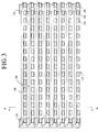
- This display device comprises a number of louver structured modules 22, one of which is shown in Fig. 3.
- the module is approximately 50cm high and 97cm wide.
- the modules are arranged in 50 columns and 19 rows per column to form a large-scale 25x19-meter display which thus includes 950 modules in total.
- the louver structured module is an integrally formed structure comprising left and right posts 24 and eight horizontally parallel, uniformly spaced beams 26 connected thereto.
- Each beam has 16 LED lamps 28 mounted on its front panel 30 and corresponding drive circuits for each of the lamps.
- the lamps have uniform horizontal pitches, which are almost the same as those between the vertically adjacent beams.
- the spaces between the adjacent beams are 32mm wide, so that the visibility through the module are maintained when seen from apart.
- Figs. 6A and 6B show the structure of a beam with LED lamps.
- Each LED combination lamp comprises 20 diodes including red (R), green (G) and blue (B) ones. This combination of 20 LEDs form one pixel of the display system.
- the combination of lamps are so arranged as to form a substantially rectangular shape, which can be maintained when lighted in any one color of the lamps.
- the number of R, G and B lamp is decided properly in consideration of the balance when displaying white color, respectively.
- Each combination of LEDs has a corresponding drive circuit board 32.
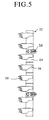
- a front panel 30 of the beam 26 pivots about the axis 34 which connects the front panel 30 and the bottom side of the beam 26 by means of a hinge structure, allowing to adjust the direction of the axis of the lamp's light.
- the beam 26 is an almost hollow-body item and contains such parts as drive circuits inside.
- a forwardly extending curvature (first curvature) portion 36 is formed in the upper front part of the beam 26, which corresponds to another curvature (second curvature) portion 38 formed in the upper part of the front panel 30, so that the second curvature can slide along over the first curvature.
- the second curvature portion 38 has slits 40 for bolts 42.
- the first curvature 36 has nut portions 44 formed at the front end thereof.
- the front panel 30 can be fixed at a proper angle by bolting the second curvature 38 to the first curvature 36.
- the angle of light emitting direction (i.e. "light axis") can he adjusted, in this embodiment, from zero to 30 degrees below the horizontal line.
- Another method for adjusting the axis' angle is to choose the appropriate panel from various ones with different axis' angles.
- the angle of the light axis can be adjusted according to the vertical level where the modules are located.
- the light axis of the module in the middle-height is directed at 15 degrees below.
- the light axes are so directed that the lower their locations are, the higher they are directed, and vise versa.
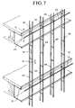
- Fig. 7 shows a schematic external view of the void space for constructing the display, with the modules being uninstalled yet.
- Support members 46 are provided extending forwardly from the front surface of the vertical guide members 44.
- the support members 46 support vertical mullions 48 at their front ends.
- These guides and mullions are, for example, rail-shaped extrusions of aluminum.
- horizontal lintels 50 are extended at predetermined vertical intervals.
- a panel of rectangular glass is installed within a set of adjacent two mullions and corresponding two lintels, being fixed by means of sash structure. Installing multiples of these glass panels will form the transparent glass wall.
- the void space between the inner surface of the glass wall and the slabs 20 forms the display space.
- the module is so installed inside the glass wall that the both horizontal sides are supported by the vertical guides 44.
- vertical channels 52 are provided in both lateral sides of the guide.
- a latch structure 54 provided on both posts 24 of the module, comprises an arm 54a, a sliding member 54b, and fixing screws 54c.
- the modules can be carried in the building and constructed from inside of the floors. First one module is set between the guides 44 by means of engaging the sliding members 54b of the latches 54 into the vertical channels 52, so that the module is fixed in a horizontal direction, but a vertical slide motion thereof is still permitted. Then the module is hooked by wire 56 using a proper stopper, hanged from a pulley placed on a higher floor, and lifted up.
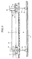
- the hollow portion has openings 24a at both vertical ends thereof.
- power and control cables which are not shown, along the hollow portion in the post 24 and they are connected, around the openings 24a, to the cables from vertically adjacent modules. Every bottom ends of the cables arranged in the respective module posts 24 is properly terminated. Every top ends of cables in the module posts 24 is connected to the corresponding power and control unit (not shown) installed upon the eighth floor's slab.
- the inner transparent glass wall is constructed on each floor separately. As shown in Fig.9, H beams 58 are provided behind every other vertical guides 44. Each H beam 58 extends from the floor to the ceiling at every floor level. A sash 60 is installed between the adjacent II beams 58. A pair of horizontally sliding windows 62 with transparent glass panel is installed in the sash 60. All the sashes and glass windows will form the whole inner glass wall.
- the building may have a structure that the outer glass wall is constructed without lintels.
- the method of establishing communication between the modules may be achieved by wireless, like an infrared communication, by means of providing the optical communication units in every module.
- the unit may be installed inside the beam 26, or preferably inside both ends of the post 24, where the modules are mechanically connected or come closest to each other. This wireless communication makes it very easy and simple to link the respective terminals of the control cables while installing the modules.
- the power cables may be prepared as long, integrally formed cables which is as long as the height of a module post 24.
- the cable may be installed along the vertical guide 44 while or after the guide 44 is constructed.
- Each module may be connected to this power cable at corresponding connecting points.
- Vertically sliding windows may be used as means of the inner glass wall, instead of horizontally sliding windows used in the above embodiment.
- Casement windows may also be chosen, if not be used for all of the window spaces, in consideration of the conditions of construction.
Abstract
Description
- The present invention relates to a high-rise building with a large scale dot-matrix display device.
- Today numerous types and designs of display apparatus can be seen along city streets and buildings, and are utilized for various advertisement of goods and services or for delivering news. As a display screen becomes larger, it conveys more information and becomes more appealing. Taking this relationship into consideration, it would be sufficient to equip a large sign-board with lamps for delivering static information such as a picture or photograph with characters. However, for communicating variable and changing information a dot matrix CRT display is preferred since it is capable of displaying changing characters and moving images.
- Large and small display panels with a number of high-intensity LEDs arranged vertically and horizontally are used widely. These types of display panels, whether small or large, have a substantially thick and solid structure. They include electronic circuits mounted on the back side of the panels to drive the LEDs arranged on the front side. Typically, with displays such as these, one side cannot be seen from another through the panel or lights located beyond the display cannot be seen from outside.
- However, in today's planning and designing of commercial buildings and event halls with various types of facades such as a curtain wall, there is a need for a super-large scale dot matrix display device maintaining visibility through the display device as well as the facade. Obviously the above conventional display devices with a solid panel structure cannot be employed for this use.
- The present applicants proposed a transparent display device which can be divided into panels which can satisfy the above needs, in the Japanese patent application No.9-68457 (dated on March 21, 1997). That panel can be applied to middle and large scale buildings and the disclosure about the method of controlling the whole display in the above application can be utilized to the present application. But if the display device is very large and the building on which the device is mounted is very high, it is difficult to construct and maintain the device.
- According to the present invention, a large scale display device can be constructed inside the transparent glass exterior by installing multiple modules in rows and columns. Each module has a louver structure, wherein the multiple beams are laid across the plural posts. Each beam has multiple LED lamps installed in its front panel at substantially uniform intervals. Thus, the modules can be transparent through the gaps between the beams, allowing to maintain good visibility through the display device as well as to let in the natural light from outside. In particular, when someone wants to see the outside from within the building, the horizontal beams will not obstruct the line of sight like an ordinary window shade. The posts of modules and the mullions adjacent thereto offer only modest interference with a horizontal line of sight. Those vertical obstacles can be removed by proper choice of positioning and the orientation of the viewers face. Accordingly, the transparent display device can maintain comfortable living space inside the building and create an appealing, wide variety of images shown on a large scale display area provided thereby.
- Moreover, the relatively small modules are easier to carry, and constructing the whole display device as well as connecting cables and maintaining the device is also simplified. To improve the performance of the device all that is needed is to replace the modules. In particular, there is no need to carry around and replace the other members of the building like the glass wall, the mullions and the vertical guides. Thus, it is possible to save natural resources and construction costs, and to reduce the construction time.
- Examples of the present invention will now be described in detail with reference to the accompanying drawings, in which:
- Fig. 1 is an external view of a façade of a high-rise building in accordance with the present invention;
- Fig. 2 is a detailed horizontal section view of the right half of the building around the outer wall shown in Fig. 1;
- Fig. 3 is a schematic representation of one louver module of a display device to be installed on the building;
- Fig. 4 is a front view of the module shown in Fig.3;
- Fig. 5 is a section view taken along the line A-A shown in Fig.3;
- Fig. 6A is a section view of the beam of the module;
- Fig.6B is an enlarged perspective view of the Fig 6A section;
- Fig. 7 is a schematic view of the void before the modules are installed;
- Fig. 8 is a schematic representation of installing the modules along the vertical guide; and,
- Fig. 9 is a detailed horizontal section view between the outer and the inner glass walls.
-
- Fig. 1 shows an external view of a
building 10 as one embodiment of the present invention. Fig. 2 shows an outline of the internal structure. The building has a curtain wall structure as its façade and is eleven stories high. The seventh floor is twice as high as any other floor, for it is to have a movie theater therein. The front facade is formed of a transparentouter glass wall 12. There is a void space (display space) 14 for installing adisplay device 16 inside the outer wall, extending from the third floor to the seventh. On the third to seventh floor'sslabs 20, there constructed innertransparent glass walls 18 further inside of the display space. A large scale display device is installed within said display space, extending from the top of the third floor to the bottom of the eighth. - The
display device 16 has a size of 25m by 19m. The display incorporates a 400 by 304 dot pattern, which means that the dots have a pitch of a little more than 6cm in both directions. This display device comprises a number of louver structuredmodules 22, one of which is shown in Fig. 3. The module is approximately 50cm high and 97cm wide. The modules are arranged in 50 columns and 19 rows per column to form a large-scale 25x19-meter display which thus includes 950 modules in total. - As shown in Fig. 3 to Fig. 5, the louver structured module is an integrally formed structure comprising left and
right posts 24 and eight horizontally parallel, uniformly spacedbeams 26 connected thereto. Each beam has 16LED lamps 28 mounted on itsfront panel 30 and corresponding drive circuits for each of the lamps. The lamps have uniform horizontal pitches, which are almost the same as those between the vertically adjacent beams. In this way, a louver structured module has 128 (= 8x16 ) LEDs at uniform pitches both on the vertical and horizontal axes. The spaces between the adjacent beams are 32mm wide, so that the visibility through the module are maintained when seen from apart. - Figs. 6A and 6B show the structure of a beam with LED lamps. Each LED combination lamp comprises 20 diodes including red (R), green (G) and blue (B) ones. This combination of 20 LEDs form one pixel of the display system. The combination of lamps are so arranged as to form a substantially rectangular shape, which can be maintained when lighted in any one color of the lamps. The number of R, G and B lamp is decided properly in consideration of the balance when displaying white color, respectively. Each combination of LEDs has a corresponding
drive circuit board 32. - A
front panel 30 of thebeam 26 pivots about theaxis 34 which connects thefront panel 30 and the bottom side of thebeam 26 by means of a hinge structure, allowing to adjust the direction of the axis of the lamp's light. Thebeam 26 is an almost hollow-body item and contains such parts as drive circuits inside. A forwardly extending curvature (first curvature)portion 36 is formed in the upper front part of thebeam 26, which corresponds to another curvature (second curvature)portion 38 formed in the upper part of thefront panel 30, so that the second curvature can slide along over the first curvature. Thesecond curvature portion 38 hasslits 40 forbolts 42. Thefirst curvature 36 hasnut portions 44 formed at the front end thereof. Thefront panel 30 can be fixed at a proper angle by bolting thesecond curvature 38 to thefirst curvature 36. - The angle of light emitting direction (i.e. "light axis") can he adjusted, in this embodiment, from zero to 30 degrees below the horizontal line. Another method for adjusting the axis' angle is to choose the appropriate panel from various ones with different axis' angles.
- The angle of the light axis can be adjusted according to the vertical level where the modules are located. In one example, the light axis of the module in the middle-height is directed at 15 degrees below. For the modules positioned lower, the light axes are so directed that the lower their locations are, the higher they are directed, and vise versa.
- Fig. 7 shows a schematic external view of the void space for constructing the display, with the modules being uninstalled yet. There installed
vertical guide members 44 along an end portion of eachslab 20 of the respective level at about one-meter intervals.Support members 46 are provided extending forwardly from the front surface of thevertical guide members 44. Thesupport members 46 supportvertical mullions 48 at their front ends. These guides and mullions are, for example, rail-shaped extrusions of aluminum. Between theadjacent mullions 48,horizontal lintels 50 are extended at predetermined vertical intervals. A panel of rectangular glass is installed within a set of adjacent two mullions and corresponding two lintels, being fixed by means of sash structure. Installing multiples of these glass panels will form the transparent glass wall. The void space between the inner surface of the glass wall and theslabs 20 forms the display space. - As shown in Fig. 8 and Fig. 9. the module is so installed inside the glass wall that the both horizontal sides are supported by the vertical guides 44. In both lateral sides of the guide,
vertical channels 52 are provided. Alatch structure 54, provided on bothposts 24 of the module, comprises anarm 54a, a slidingmember 54b, and fixingscrews 54c. The modules can be carried in the building and constructed from inside of the floors. First one module is set between theguides 44 by means of engaging the slidingmembers 54b of thelatches 54 into thevertical channels 52, so that the module is fixed in a horizontal direction, but a vertical slide motion thereof is still permitted. Then the module is hooked bywire 56 using a proper stopper, hanged from a pulley placed on a higher floor, and lifted up. Then another module is set directly below the first one, where the first one was located before lifted, again by means of engaging thelatches 54 into thevertical channels 52. After repeating these steps urtil all of the modules for a certain floor are installed, the pulley is removed and the wire remains to support the modules. For further secure support of the modules, holder members, not shown in the figures, are provided extending forwardly from the vertical guide at proper intervals so that each holder can support right amounts of modules. - There is a hollow space extending vertically within the
post 24 of the module. The hollow portion hasopenings 24a at both vertical ends thereof. There are provided power and control cables, which are not shown, along the hollow portion in thepost 24 and they are connected, around theopenings 24a, to the cables from vertically adjacent modules. Every bottom ends of the cables arranged in the respective module posts 24 is properly terminated. Every top ends of cables in the module posts 24 is connected to the corresponding power and control unit (not shown) installed upon the eighth floor's slab. - The inner transparent glass wall is constructed on each floor separately. As shown in Fig.9, H beams 58 are provided behind every other
vertical guides 44. EachH beam 58 extends from the floor to the ceiling at every floor level. Asash 60 is installed between the adjacent II beams 58. A pair of horizontally slidingwindows 62 with transparent glass panel is installed in thesash 60. All the sashes and glass windows will form the whole inner glass wall. - As is publicity known, the building may have a structure that the outer glass wall is constructed without lintels.
- When the horizontal dimension of the louver structured module is rather large so as to degrade the rigidity of the beam is rather low, the beam is liable to bend around the center. Several additional posts for supporting the beams may be provided at proper pitches to avoid the above drawback.
- The method of establishing communication between the modules may be achieved by wireless, like an infrared communication, by means of providing the optical communication units in every module. The unit may be installed inside the
beam 26, or preferably inside both ends of thepost 24, where the modules are mechanically connected or come closest to each other. This wireless communication makes it very easy and simple to link the respective terminals of the control cables while installing the modules. - The power cables may be prepared as long, integrally formed cables which is as long as the height of a
module post 24. The cable may be installed along thevertical guide 44 while or after theguide 44 is constructed. Each module may be connected to this power cable at corresponding connecting points. - Vertically sliding windows may be used as means of the inner glass wall, instead of horizontally sliding windows used in the above embodiment. Casement windows may also be chosen, if not be used for all of the window spaces, in consideration of the conditions of construction.
Claims (17)
- A high-rise building (10) with a large scale dot-matrix display device (16) comprising:a plurality of glass panels arranged in rows and columns to form a curtain wall structured transparent outer wall (12) extending over an exterior of the building, each of said panels being installed apart from end portions of floor slabs (20) of the building to form a void space (14) therebetween;a plurality of louver structured modules (22) arranged within said void space in rows and columns to form a large scale display area, each of said modules (22) having a louver-like structure formed of a plurality of posts (24) arranged in substantially parallel relationship and a plurality of parallel, uniformly spaced beams (26) connecting said adjacent posts (24);a plurality of light emitting means (28) mounted on each of said beams (26) at uniform and generally the same pitches as those between said adjacent beams to form said large-scale dot-matrix display;a plurality of drive circuits (32) for driving the respective light emitting means (28) installed in each of said beams;a plurality of vertical guide members (44) fixed to said end portions of the floor slabs (20), said vertical guide members (44) being arranged substantially in parallel relationship so that said modules (22) are supported between said adjacent guides at the both lateral sides thereof; and,a plurality of vertical mullion members (48) fixed to said vertical guide members (44) as spaced apart from each of said vertical guides (44), so that said glass panels are supported therebetween.
- A high-rise building according to claim 1, wherein a transparent inner glass wall (18) is disposed at an inner proximity of said void space (14), said louver structured modules (22) being disposed within said void space defined between said inner (18) and exterior (12) glass walls.
- A high-rise building according to claim 1 or 2, wherein axes of light emission of said light emitting means (28) are shifted downward as said louver structured modules (22) are positioned at higher levels of the building.
- A high-rise building according to any preceding claim, wherein said light emitting means (28) comprises a plurality of LEDs.
- A high-rise building according to any preceding claim, wherein a plurality of support members (46) are provided extending forwardly from the front surface of said vertical guide members (44) for supporting said mullion members (48).
- A high-rise building with a large scale dot-matrix display device comprising:a plurality of transparent panels arranged in rows and columns to form a curtain wall structured transparent outer wall (12) extending over an exterior of the building (10), each of said panels being installed apart from end portions of floor slabs (20) of the building to form a void space (14) therebetween;a plurality of louver structured modules (22) disposed within said void space and arranged in rows and columns to form said large scale display device, each of said modules (22) having a louver-like structure formed of a plurality of vertical posts and a plurality of horizontal beams (26) connecting said vertical posts (24);a plurality of light emitting means (28) mounted on each of said horizontal beams (26) at predetermined pitches so as to form said large-scale dot-matrix display area;a plurality of drive circuits (32) disposed in each of said beams (26) for driving the respective light emitting means (28) mounted on said beams (26); and,means for holding said modules within said void space.
- A high-rise building with a large scale dot-matrix display device according to claim 6, wherein a transparent inner wall (18) is provided at an inner proximity of said void space (14) and said louver structured modules (22) are disposed within said void space (14) defined between said inner and outer walls.
- A high-rise building with a large scale dot-matrix display device according to claim 6 or 7, wherein axes of light emission of said light emitting means (28) are shifted downward as said louver structured modules (22) are positioned at higher levels of the building.
- A high-rise building with a large scale dot-matrix display device according to any of claims 6 to 8, wherein said light emitting means (28) comprises a plurality of LEDs.
- A louver structured module (12) for use in a high-rise building according to any preceding claim.
- A high-rise building with a large scale dot-matrix display device comprising:a transparent exterior wall arranged as spaced apart from end portions of floor slabs of the building;a plurality of louver-like structured modules disposed between said transparent exterior wall (12) and the end portions of the floor slabs (20) of the building arranged in rows and columns to form a large scale display device inside the transparent exterior walls (12), each of said modules (22) formed of a plurality of vertical posts (24) and a plurality of horizontal beams (26) connecting said vertical posts (24), each of said louver-like structured modules (22) having a plurality of light emitting means (28) mounted on each of said horizontal beams (26) thereof at predetermined pitches so as to form said large-scale dot-matrix display;a plurality of drive circuits (32) disposed in each of said beams (26) for driving the respective light emitting means (28) mounted on said beams (26); and,means for holding said modules between said transparent exterior wall (12) and the end portions of the floor slabs (20) of the building.
- A high-rise building with a large scale dot-matrix display device according to claim 11, wherein a transparent inner wall (18) is positioned at said end portions of the floor slabs (20) of the building and said louver structured modules (22) are disposed within a void space defined between said inner (18) and exterior (12) walls.
- A high-rise building with a large scale dot-matrix display device according to claim 11 or 12, wherein axes of light emission of said light emitting means are shifted downward as said louver structured modules are positioned at higher levels of the building.
- A high-rise building according to any of claims 11 to 13, wherein said light emitting means (28) comprises a plurality of LEDs.
- A louver structured display module comprising:a plurality of vertical posts (24) arranged in substantially parallel relationship to each other;a plurality of horizontal beams (26) connecting said adjacent vertical posts (24), the adjacent horizontal beams being spaced apart at predetermined intervals;a plurality of light emitting means (28) mounted on each of said horizontal beams (26) at predetermined pitches so as to form a dot-matrix display; and,a plurality of drive circuits (32) disposed in each of said beams for driving the respective light emitting means mounted on said beams.
- A louver structured display module according to claim 15, wherein each light emitting means (28) is disposed on the horizontal beam in rotatable manner around a longitudinal axis of the beam so that an axis of light emission of said light emitting means (28) is changeable in an up-and-down direction.
- A louver structured display module according to claim 15 or 16, wherein said light emitting means (28) comprises a plurality of LEDs.
Applications Claiming Priority (4)
| Application Number | Priority Date | Filing Date | Title |
|---|---|---|---|
| JP30565898 | 1998-10-27 | ||
| JP30565898A JP4176209B2 (en) | 1998-10-27 | 1998-10-27 | A high-rise building equipped with a huge screen display facing outside inside the transparent glass outer wall |
| JP00138299A JP4744658B2 (en) | 1999-01-06 | 1999-01-06 | Louver structure module constituting a huge screen display |
| JP138299 | 1999-01-06 |
Publications (3)
| Publication Number | Publication Date |
|---|---|
| EP0997865A2 true EP0997865A2 (en) | 2000-05-03 |
| EP0997865A3 EP0997865A3 (en) | 2000-11-02 |
| EP0997865B1 EP0997865B1 (en) | 2006-06-21 |
Family
ID=26334591
Family Applications (1)
| Application Number | Title | Priority Date | Filing Date |
|---|---|---|---|
| EP99308485A Expired - Lifetime EP0997865B1 (en) | 1998-10-27 | 1999-10-27 | A high-rise building having a large scale display device |
Country Status (13)
| Country | Link |
|---|---|
| US (1) | US6237290B1 (en) |
| EP (1) | EP0997865B1 (en) |
| KR (1) | KR100641513B1 (en) |
| CN (1) | CN1178187C (en) |
| AT (1) | ATE331272T1 (en) |
| AU (1) | AU775399B2 (en) |
| BR (1) | BR9904946A (en) |
| CA (1) | CA2287439C (en) |
| DE (1) | DE69932014T2 (en) |
| ES (1) | ES2267230T3 (en) |
| HK (1) | HK1027655A1 (en) |
| RU (2) | RU2325495C2 (en) |
| TW (1) | TW425533B (en) |
Cited By (9)
| Publication number | Priority date | Publication date | Assignee | Title |
|---|---|---|---|---|
| WO2001022394A1 (en) * | 1999-09-22 | 2001-03-29 | Lighthouse Communications Gmbh | Method and device for generating a high-resolution large image |
| WO2002029771A1 (en) * | 2000-10-05 | 2002-04-11 | Takenaka Corporation | Prefixed advertisement structure integrated with glass sash wall of building |
| EP1293955A3 (en) * | 2001-09-14 | 2003-09-17 | Kast Co., Ltd. | Display apparatus |
| EP1594109A1 (en) * | 2004-05-03 | 2005-11-09 | LUMINO Licht Elektronik GmbH | Display device |
| WO2006023228A1 (en) * | 2004-08-20 | 2006-03-02 | Wynn Resorts Holding, Llc | Display and method of operation |
| US8021020B2 (en) | 2007-07-16 | 2011-09-20 | Cambridge International Inc. | Lighted architectural mesh |
| US8081145B2 (en) | 2005-11-01 | 2011-12-20 | Lumino Licht Elektronik Gmbh | Display device |
| US8317352B2 (en) | 2008-12-11 | 2012-11-27 | Robert Saccomanno | Non-invasive injection of light into a transparent substrate, such as a window pane through its face |
| WO2023235874A1 (en) * | 2022-06-03 | 2023-12-07 | Daktronics, Inc. | Adjustable mounting frame for an electronic display |
Families Citing this family (64)
| Publication number | Priority date | Publication date | Assignee | Title |
|---|---|---|---|---|
| US6720745B2 (en) * | 1997-08-26 | 2004-04-13 | Color Kinetics, Incorporated | Data delivery track |
| US7132804B2 (en) * | 1997-12-17 | 2006-11-07 | Color Kinetics Incorporated | Data delivery track |
| US7303300B2 (en) | 2000-09-27 | 2007-12-04 | Color Kinetics Incorporated | Methods and systems for illuminating household products |
| KR100432201B1 (en) * | 2000-12-30 | 2004-05-20 | 김시환 | An advertisement apparatus for using a light swiching device |
| US7358929B2 (en) * | 2001-09-17 | 2008-04-15 | Philips Solid-State Lighting Solutions, Inc. | Tile lighting methods and systems |
| EP1620676A4 (en) | 2003-05-05 | 2011-03-23 | Philips Solid State Lighting | Lighting methods and systems |
| KR200337156Y1 (en) * | 2003-06-03 | 2003-12-31 | 김석배 | Construction tile-type material using light source |
| US7477140B1 (en) | 2003-12-26 | 2009-01-13 | Booth Kenneth C | See-through lighted information display |
| KR100605137B1 (en) | 2004-08-11 | 2006-07-28 | 주식회사 한국싸인 | Combination structure of a LED module |
| US7543956B2 (en) * | 2005-02-28 | 2009-06-09 | Philips Solid-State Lighting Solutions, Inc. | Configurations and methods for embedding electronics or light emitters in manufactured materials |
| GB2441921B (en) * | 2005-05-17 | 2010-09-22 | Nervecorp Ltd | Building structures having electrically functional architectural surfaces |
| US7877910B2 (en) * | 2006-01-11 | 2011-02-01 | Barco, Inc. | Display system |
| US20070182666A1 (en) * | 2006-02-01 | 2007-08-09 | Element Labs, Inc. | Curtain display unit for light emitting elements |
| US7777699B2 (en) | 2006-05-01 | 2010-08-17 | Barco, Inc. | Display system having pixels |
| DE102006037878A1 (en) * | 2006-08-11 | 2008-02-14 | Haver & Boecker Ohg | Illuminated fabric and method for its production |
| US20080043003A1 (en) * | 2006-08-17 | 2008-02-21 | Vogsland Robin O | Smart display pixel |
| US20100103662A1 (en) * | 2006-12-01 | 2010-04-29 | Element Labs, Inc. | Pixel Support System |
| US8152324B2 (en) * | 2007-01-12 | 2012-04-10 | Barco, Inc. | Rod assembly connector for mounting light emitting display apparatuses |
| US20100090927A1 (en) * | 2007-03-08 | 2010-04-15 | Element Labs, Inc. | Ladder Display System |
| US7665874B2 (en) * | 2007-03-30 | 2010-02-23 | Chadwell Thomas J | Method and apparatus for delivering visual information |
| US20080244943A1 (en) * | 2007-04-06 | 2008-10-09 | Element Labs, Inc. | Variable Baffle for Low Resolution Displays |
| DE102008009775A1 (en) * | 2007-07-03 | 2009-01-08 | Döppner Bauelemente GmbH & Co. KG | Large-area display device i.e. transparent multimedia facade, for building, has transparent elements with substrate on which lighting elements i.e. LEDs, are arranged, where power supply of LEDs takes place over conducting paths |
| EP2179632B1 (en) * | 2007-07-03 | 2010-11-17 | Schott AG | Substrate comprising a highly conductive layer |
| EP2081172A1 (en) | 2008-01-18 | 2009-07-22 | G-LEC Europe GmbH | Display panel and display system |
| FR2932307B1 (en) * | 2008-06-09 | 2011-10-28 | Citiled | DEVICE FOR DISPLAYING A VIDEO IMAGE ON AN EDIFICE |
| US20100017735A1 (en) * | 2008-07-15 | 2010-01-21 | Unisys Corporation | Decentralized hardware partitioning within a multiprocessing computing system |
| US20100071282A1 (en) * | 2008-09-23 | 2010-03-25 | Mark Tofflemire | Unitized Building Integrated Photovoltaic Conversion Module Adapted With Electrical Conduits |
| US8070310B2 (en) * | 2009-02-18 | 2011-12-06 | Ronald Paul Harwood | Window lighting system |
| US9898240B2 (en) * | 2010-01-25 | 2018-02-20 | Prismview, Llc | Systems, devices, and methods relating to an electronic display |
| WO2012077103A1 (en) * | 2010-12-08 | 2012-06-14 | Nervecorp Limited | Electrically operated building facade display system |
| KR101142287B1 (en) | 2012-02-17 | 2012-05-07 | 주식회사 포스코아이씨티 | Motorized variable display louvre apparatus |
| BE1019935A3 (en) * | 2012-03-08 | 2013-02-05 | Tait Technologies Bvba | SYSTEM FOR VIDEO VIEWING. |
| DK2841844T3 (en) * | 2012-04-27 | 2017-11-06 | Schreder | IMPROVEMENTS OR RELATING TO MULTI-COLOR LIGHT SOURCES |
| CN102637392B (en) * | 2012-05-03 | 2014-05-28 | 温州大学 | LED (light emitting diode) glass curtain wall |
| KR101178275B1 (en) | 2012-05-22 | 2012-08-29 | (주)하이브시스템 | Screen apparatus of display wall |
| KR101390222B1 (en) * | 2012-08-10 | 2014-04-30 | 주식회사 엘이디 에비뉴 | Display apparatus |
| KR20150052056A (en) * | 2012-09-03 | 2015-05-13 | 미라이 키카쿠 가부시키가이샤 | Window structure body |
| CN105247150B (en) | 2013-02-19 | 2018-01-09 | 梦光控股公司 | Entertain venue and the system/method of correlation |
| WO2014130459A1 (en) | 2013-02-19 | 2014-08-28 | Dreamlight Holdings Inc., Formerly Known As A Thousand Miles Llc | Rotating performance stage |
| WO2014130461A1 (en) | 2013-02-19 | 2014-08-28 | Dreamlight Holdings Inc., Formerly Known As A Thousand Miles Llc | Immersive sound system |
| US8944609B2 (en) | 2013-02-19 | 2015-02-03 | DreamLight Holdings Inc. | Compositing screen |
| EP2974305A2 (en) * | 2013-03-11 | 2016-01-20 | Koninklijke Philips N.V. | Transparent autostereoscopic display |
| US10210778B2 (en) | 2013-03-16 | 2019-02-19 | Adti Media Llc | Sign construction with sectional sign assemblies and installation kit and method of using same |
| US9047791B2 (en) | 2013-03-16 | 2015-06-02 | Adti Media, Llc. | Sign construction with sectional sign assemblies and installation kit and method of using same |
| US8929083B2 (en) | 2013-03-16 | 2015-01-06 | ADIT Media, LLC | Compound structural frame and method of using same for efficient retrofitting |
| US9761157B2 (en) | 2013-03-16 | 2017-09-12 | Adti Media Llc | Customized sectional sign assembly kit and method of using kit for construction and installation of same |
| US8824125B1 (en) | 2013-03-16 | 2014-09-02 | ADTI Media, LLC | Modular installation and conversion kit for electronic sign structure and method of using same |
| US9852666B2 (en) | 2013-03-16 | 2017-12-26 | Adti Media Llc | Full height sectional sign assembly and installation kit and method of using same |
| US9582237B2 (en) | 2013-12-31 | 2017-02-28 | Ultravision Technologies, Llc | Modular display panels with different pitches |
| US20150187237A1 (en) | 2013-12-31 | 2015-07-02 | Ultravision Holdings, Llc | System and Method for a Modular Multi-Panel Display |
| US9207904B2 (en) | 2013-12-31 | 2015-12-08 | Ultravision Technologies, Llc | Multi-panel display with hot swappable display panels and methods of servicing thereof |
| US9195281B2 (en) | 2013-12-31 | 2015-11-24 | Ultravision Technologies, Llc | System and method for a modular multi-panel display |
| US9416551B2 (en) | 2013-12-31 | 2016-08-16 | Ultravision Technologies, Llc | Preassembled display systems and methods of installation thereof |
| US9311847B2 (en) | 2014-07-16 | 2016-04-12 | Ultravision Technologies, Llc | Display system having monitoring circuit and methods thereof |
| KR20160016413A (en) | 2014-08-05 | 2016-02-15 | 삼성전자주식회사 | Display system and control method of the same |
| KR101703272B1 (en) * | 2015-02-09 | 2017-02-06 | 주식회사 대한전광 | Display louvre apparatus |
| US9279573B1 (en) | 2015-02-09 | 2016-03-08 | Nanolumens Acquisition, Inc. | Front serviceable mounting apparatus and methods |
| IL243064B (en) * | 2015-12-14 | 2019-12-31 | Carmel Aviv | Low drag outdoor media facade display |
| CN105683659B (en) * | 2016-01-17 | 2019-04-05 | 新昌县以琳环保科技有限公司 | External wall display device and heat supply display methods with solar energy unit |
| DE102016216381A1 (en) * | 2016-08-31 | 2018-03-01 | Robert Bosch Gmbh | Display unit, display device comprising at least one display unit and use of the display unit and the display device |
| ES1215126Y (en) * | 2018-05-07 | 2018-09-26 | De Miguel Raul Martinez | TRANSPARENT LIGHT SECURITY CLOSURE |
| EP3821099A1 (en) * | 2018-07-10 | 2021-05-19 | Prof. Michael Lange Ingenieurgesellschaft Mbh | Building envelope comprising a multi-functional glass element |
| US11536043B2 (en) * | 2018-08-06 | 2022-12-27 | Jeffrey J. Konczak | Modular mini building system for parking lots |
| CN112177204B (en) * | 2020-08-21 | 2021-08-31 | 中铁工程设计咨询集团有限公司 | Reverse installation type glass curtain wall and high-speed rail station comprising same |
Citations (4)
| Publication number | Priority date | Publication date | Assignee | Title |
|---|---|---|---|---|
| DE2149469A1 (en) * | 1971-10-04 | 1973-05-17 | Ritter Aluminium Gmbh | LIGHT SIGN SYSTEM FOR BUILDING FACADES |
| US4447995A (en) * | 1982-04-21 | 1984-05-15 | Neal J. Mosely | Building with illuminated sign |
| US5191748A (en) * | 1991-12-12 | 1993-03-09 | Baughman Daniel G | Illuminated display |
| EP0869468A2 (en) * | 1997-03-21 | 1998-10-07 | Avix Inc. | A method of displaying a high-density dot-matrix image data and system therefor |
Family Cites Families (25)
| Publication number | Priority date | Publication date | Assignee | Title |
|---|---|---|---|---|
| US4365245A (en) | 1978-06-05 | 1982-12-21 | Colmenero Gustavo T | Display module for traveling pattern signs |
| US4970502A (en) | 1979-08-27 | 1990-11-13 | Sharp Kabushiki Kaisha | Running character display |
| US4358761A (en) | 1979-09-28 | 1982-11-09 | Sanyo Electric Co. Ltd. | Dot matrix display apparatus |
| US4386351A (en) | 1980-12-20 | 1983-05-31 | Timex Corporation | Method and system for two-dimensional traveling display and driver circuits therefor |
| US4460142A (en) | 1982-02-04 | 1984-07-17 | Rorke Blondale O | Bracket for supporting a sign to a cylindrical post |
| US4447998A (en) * | 1982-03-05 | 1984-05-15 | Griffin Kary A | Floor panel |
| US4791744A (en) * | 1983-04-29 | 1988-12-20 | Thomas A. Schutz & Co. | Adjustable price display |
| FR2566934B1 (en) | 1984-06-29 | 1987-05-07 | Giraud Daniel | METHOD FOR DISPLAYING INFORMATION SUCH AS FOR EXAMPLE ADVERTISING MESSAGES ON A NUMBER OF PANELS WITH DISPLAY ELEMENTS PLACED IN A PLACE OF SPORTS EVENTS AND SYSTEM FOR CARRYING OUT SUCH A METHOD |
| US4750130A (en) | 1985-03-20 | 1988-06-07 | Tokyo Tatsuno Co., Ltd. | Fuel delivery display and control system |
| US5239798A (en) * | 1987-10-30 | 1993-08-31 | Kajima Corporation | External wall panel and mounting structure thereof |
| GB8908322D0 (en) | 1989-04-13 | 1989-06-01 | Stellar Communicat Ltd | Display |
| DE4022441C1 (en) * | 1990-07-14 | 1991-10-17 | Alco-Systeme Gmbh, 4400 Muenster, De | |
| US5162696A (en) | 1990-11-07 | 1992-11-10 | Goodrich Frederick S | Flexible incasements for LED display panels |
| AU1998192A (en) * | 1991-05-20 | 1992-12-30 | Big Unlimited | Method and apparatus for creating design insulated glass |
| JP2818984B2 (en) * | 1992-03-04 | 1998-10-30 | 株式会社 ケー・シー・シー・商会 | Illuminated display for mosaic panels |
| US5641141A (en) | 1994-10-06 | 1997-06-24 | At&T Wireless Services, Inc. | Antenna mounting system |
| JP2802049B2 (en) | 1994-10-25 | 1998-09-21 | アビックス株式会社 | Scroll display |
| JPH0916107A (en) * | 1995-04-28 | 1997-01-17 | Copal Co Ltd | Illuminated display unit |
| US5650794A (en) | 1995-05-19 | 1997-07-22 | Walsh; William F. | Repeat electronic display device |
| US6028582A (en) * | 1995-12-18 | 2000-02-22 | Reader Vision, Inc. | Solenoid for scanned flip-disk sign improvements |
| US5900850A (en) | 1996-08-28 | 1999-05-04 | Bailey; James Tam | Portable large scale image display system |
| JP3756615B2 (en) | 1997-03-21 | 2006-03-15 | アビックス株式会社 | Lattice module for constructing a large-screen perspective display panel by connecting multiple modules |
| KR100257099B1 (en) * | 1997-05-09 | 2000-05-15 | 도요따로 도끼모도 | Method for presenting large scrolling display along window of building and apparatus therefor |
| US6000812A (en) * | 1997-11-17 | 1999-12-14 | Mark Iv Industries Limited | Writable disk sign |
| US5996263A (en) * | 1998-01-16 | 1999-12-07 | Readervision, Inc. | Internally illuminated matrix sign |
-
1999
- 1999-10-25 TW TW088118411A patent/TW425533B/en not_active IP Right Cessation
- 1999-10-25 AU AU56055/99A patent/AU775399B2/en not_active Ceased
- 1999-10-26 RU RU2004123677/03A patent/RU2325495C2/en not_active IP Right Cessation
- 1999-10-26 RU RU99122609/03A patent/RU2243342C2/en not_active IP Right Cessation
- 1999-10-26 KR KR1019990046537A patent/KR100641513B1/en not_active IP Right Cessation
- 1999-10-26 BR BR9904946-5A patent/BR9904946A/en not_active Application Discontinuation
- 1999-10-26 CA CA002287439A patent/CA2287439C/en not_active Expired - Fee Related
- 1999-10-27 US US09/428,328 patent/US6237290B1/en not_active Expired - Lifetime
- 1999-10-27 EP EP99308485A patent/EP0997865B1/en not_active Expired - Lifetime
- 1999-10-27 ES ES99308485T patent/ES2267230T3/en not_active Expired - Lifetime
- 1999-10-27 AT AT99308485T patent/ATE331272T1/en not_active IP Right Cessation
- 1999-10-27 DE DE69932014T patent/DE69932014T2/en not_active Expired - Fee Related
- 1999-10-27 CN CNB991231732A patent/CN1178187C/en not_active Expired - Fee Related
-
2000
- 2000-10-19 HK HK00106653A patent/HK1027655A1/en not_active IP Right Cessation
Patent Citations (4)
| Publication number | Priority date | Publication date | Assignee | Title |
|---|---|---|---|---|
| DE2149469A1 (en) * | 1971-10-04 | 1973-05-17 | Ritter Aluminium Gmbh | LIGHT SIGN SYSTEM FOR BUILDING FACADES |
| US4447995A (en) * | 1982-04-21 | 1984-05-15 | Neal J. Mosely | Building with illuminated sign |
| US5191748A (en) * | 1991-12-12 | 1993-03-09 | Baughman Daniel G | Illuminated display |
| EP0869468A2 (en) * | 1997-03-21 | 1998-10-07 | Avix Inc. | A method of displaying a high-density dot-matrix image data and system therefor |
Cited By (17)
| Publication number | Priority date | Publication date | Assignee | Title |
|---|---|---|---|---|
| WO2001022394A1 (en) * | 1999-09-22 | 2001-03-29 | Lighthouse Communications Gmbh | Method and device for generating a high-resolution large image |
| US7254923B2 (en) | 2000-10-05 | 2007-08-14 | Takenaka Corporation | Prefixed advertisement structure integrated with glass sash wall of building |
| WO2002029771A1 (en) * | 2000-10-05 | 2002-04-11 | Takenaka Corporation | Prefixed advertisement structure integrated with glass sash wall of building |
| GB2383887A (en) * | 2000-10-05 | 2003-07-09 | Takenaka Corp | Prefixed advertisement structure integrated with glass sash wall of building |
| GB2383887B (en) * | 2000-10-05 | 2004-05-05 | Takenaka Corp | Prefixed advertisement structure integrated with glass sash wall of building |
| EP1293955A3 (en) * | 2001-09-14 | 2003-09-17 | Kast Co., Ltd. | Display apparatus |
| EP1594109A1 (en) * | 2004-05-03 | 2005-11-09 | LUMINO Licht Elektronik GmbH | Display device |
| US7525510B2 (en) | 2004-08-20 | 2009-04-28 | Wynn Resorts Holdings, Llc | Display and method of operation |
| WO2006023228A1 (en) * | 2004-08-20 | 2006-03-02 | Wynn Resorts Holding, Llc | Display and method of operation |
| US8081145B2 (en) | 2005-11-01 | 2011-12-20 | Lumino Licht Elektronik Gmbh | Display device |
| US8021020B2 (en) | 2007-07-16 | 2011-09-20 | Cambridge International Inc. | Lighted architectural mesh |
| US8360610B2 (en) | 2007-07-16 | 2013-01-29 | Cambridge International Inc. | Lighted architectural mesh |
| US8317352B2 (en) | 2008-12-11 | 2012-11-27 | Robert Saccomanno | Non-invasive injection of light into a transparent substrate, such as a window pane through its face |
| US8727581B2 (en) | 2008-12-11 | 2014-05-20 | Robert Saccomanno | Optics for axially-transverse light emission |
| US9377178B2 (en) | 2008-12-11 | 2016-06-28 | Robert Saccomanno | Optics for axially-transverse light emission |
| US10048424B2 (en) | 2008-12-11 | 2018-08-14 | Luminated Glazings, Llc | Substrate with indicia configured for optical coupling |
| WO2023235874A1 (en) * | 2022-06-03 | 2023-12-07 | Daktronics, Inc. | Adjustable mounting frame for an electronic display |
Also Published As
| Publication number | Publication date |
|---|---|
| CA2287439C (en) | 2007-06-12 |
| EP0997865B1 (en) | 2006-06-21 |
| HK1027655A1 (en) | 2001-01-19 |
| KR100641513B1 (en) | 2006-10-31 |
| DE69932014T2 (en) | 2007-01-04 |
| KR20000029310A (en) | 2000-05-25 |
| EP0997865A3 (en) | 2000-11-02 |
| RU2325495C2 (en) | 2008-05-27 |
| DE69932014D1 (en) | 2006-08-03 |
| AU775399B2 (en) | 2004-07-29 |
| CN1178187C (en) | 2004-12-01 |
| ES2267230T3 (en) | 2007-03-01 |
| RU2004123677A (en) | 2006-01-20 |
| TW425533B (en) | 2001-03-11 |
| BR9904946A (en) | 2000-09-05 |
| AU5605599A (en) | 2000-05-11 |
| CN1281205A (en) | 2001-01-24 |
| RU2243342C2 (en) | 2004-12-27 |
| CA2287439A1 (en) | 2000-04-27 |
| US6237290B1 (en) | 2001-05-29 |
| ATE331272T1 (en) | 2006-07-15 |
Similar Documents
| Publication | Publication Date | Title |
|---|---|---|
| EP0997865B1 (en) | A high-rise building having a large scale display device | |
| US9851079B2 (en) | System and technique for tensioned wall of individual LED tiles | |
| US8106923B2 (en) | Flexible pixel hardware and method | |
| US20060139917A1 (en) | Light emitting diode (LED) picture element | |
| US5066947A (en) | Very large size display screen | |
| US20070218751A1 (en) | Mounting system for light tiles attached to tensioned cables | |
| JP3977837B2 (en) | Blind type display device using LED | |
| US20070176854A1 (en) | Irregular screen format for led and oled systems | |
| KR102023871B1 (en) | Fabricable display frame module | |
| JP4176209B2 (en) | A high-rise building equipped with a huge screen display facing outside inside the transparent glass outer wall | |
| JP4439901B2 (en) | Wall display device for curtain wall skyscraper | |
| KR100501951B1 (en) | Display device of used LED | |
| JP2000200054A (en) | Louver structure module constituting huge screen display | |
| KR100607666B1 (en) | Display apparatus for adjusting display direction of dot line units | |
| KR200358464Y1 (en) | Display apparatus for adjusting display direction of dot line units |
Legal Events
| Date | Code | Title | Description |
|---|---|---|---|
| PUAI | Public reference made under article 153(3) epc to a published international application that has entered the european phase |
Free format text: ORIGINAL CODE: 0009012 |
|
| AK | Designated contracting states |
Kind code of ref document: A2 Designated state(s): AT BE CH CY DE DK ES FI FR GB GR IE IT LI LU MC NL PT SE |
|
| AX | Request for extension of the european patent |
Free format text: AL;LT;LV;MK;RO;SI |
|
| PUAL | Search report despatched |
Free format text: ORIGINAL CODE: 0009013 |
|
| AK | Designated contracting states |
Kind code of ref document: A3 Designated state(s): AT BE CH CY DE DK ES FI FR GB GR IE IT LI LU MC NL PT SE |
|
| AX | Request for extension of the european patent |
Free format text: AL;LT;LV;MK;RO;SI |
|
| 17P | Request for examination filed |
Effective date: 20001206 |
|
| RAP1 | Party data changed (applicant data changed or rights of an application transferred) |
Owner name: QFRONT CO., LTD. Owner name: AVIX INC. |
|
| AKX | Designation fees paid |
Free format text: AT BE CH CY DE DK ES FI FR GB GR IE IT LI LU MC NL PT SE |
|
| 17Q | First examination report despatched |
Effective date: 20041201 |
|
| GRAP | Despatch of communication of intention to grant a patent |
Free format text: ORIGINAL CODE: EPIDOSNIGR1 |
|
| GRAS | Grant fee paid |
Free format text: ORIGINAL CODE: EPIDOSNIGR3 |
|
| GRAA | (expected) grant |
Free format text: ORIGINAL CODE: 0009210 |
|
| AK | Designated contracting states |
Kind code of ref document: B1 Designated state(s): AT BE CH CY DE DK ES FI FR GB GR IE IT LI LU MC NL PT SE |
|
| PG25 | Lapsed in a contracting state [announced via postgrant information from national office to epo] |
Ref country code: NL Free format text: LAPSE BECAUSE OF FAILURE TO SUBMIT A TRANSLATION OF THE DESCRIPTION OR TO PAY THE FEE WITHIN THE PRESCRIBED TIME-LIMIT Effective date: 20060621 Ref country code: LI Free format text: LAPSE BECAUSE OF FAILURE TO SUBMIT A TRANSLATION OF THE DESCRIPTION OR TO PAY THE FEE WITHIN THE PRESCRIBED TIME-LIMIT Effective date: 20060621 Ref country code: IT Free format text: LAPSE BECAUSE OF FAILURE TO SUBMIT A TRANSLATION OF THE DESCRIPTION OR TO PAY THE FEE WITHIN THE PRESCRIBED TIME-LIMIT;WARNING: LAPSES OF ITALIAN PATENTS WITH EFFECTIVE DATE BEFORE 2007 MAY HAVE OCCURRED AT ANY TIME BEFORE 2007. THE CORRECT EFFECTIVE DATE MAY BE DIFFERENT FROM THE ONE RECORDED. Effective date: 20060621 Ref country code: FI Free format text: LAPSE BECAUSE OF FAILURE TO SUBMIT A TRANSLATION OF THE DESCRIPTION OR TO PAY THE FEE WITHIN THE PRESCRIBED TIME-LIMIT Effective date: 20060621 Ref country code: CH Free format text: LAPSE BECAUSE OF FAILURE TO SUBMIT A TRANSLATION OF THE DESCRIPTION OR TO PAY THE FEE WITHIN THE PRESCRIBED TIME-LIMIT Effective date: 20060621 Ref country code: AT Free format text: LAPSE BECAUSE OF FAILURE TO SUBMIT A TRANSLATION OF THE DESCRIPTION OR TO PAY THE FEE WITHIN THE PRESCRIBED TIME-LIMIT Effective date: 20060621 |
|
| REG | Reference to a national code |
Ref country code: GB Ref legal event code: FG4D |
|
| REG | Reference to a national code |
Ref country code: CH Ref legal event code: EP |
|
| REG | Reference to a national code |
Ref country code: IE Ref legal event code: FG4D |
|
| REF | Corresponds to: |
Ref document number: 69932014 Country of ref document: DE Date of ref document: 20060803 Kind code of ref document: P |
|
| PG25 | Lapsed in a contracting state [announced via postgrant information from national office to epo] |
Ref country code: SE Free format text: LAPSE BECAUSE OF FAILURE TO SUBMIT A TRANSLATION OF THE DESCRIPTION OR TO PAY THE FEE WITHIN THE PRESCRIBED TIME-LIMIT Effective date: 20060921 Ref country code: DK Free format text: LAPSE BECAUSE OF FAILURE TO SUBMIT A TRANSLATION OF THE DESCRIPTION OR TO PAY THE FEE WITHIN THE PRESCRIBED TIME-LIMIT Effective date: 20060921 |
|
| PG25 | Lapsed in a contracting state [announced via postgrant information from national office to epo] |
Ref country code: IE Free format text: LAPSE BECAUSE OF NON-PAYMENT OF DUE FEES Effective date: 20061027 |
|
| REG | Reference to a national code |
Ref country code: HK Ref legal event code: GR Ref document number: 1027655 Country of ref document: HK |
|
| PG25 | Lapsed in a contracting state [announced via postgrant information from national office to epo] |
Ref country code: MC Free format text: LAPSE BECAUSE OF NON-PAYMENT OF DUE FEES Effective date: 20061031 |
|
| PG25 | Lapsed in a contracting state [announced via postgrant information from national office to epo] |
Ref country code: PT Free format text: LAPSE BECAUSE OF FAILURE TO SUBMIT A TRANSLATION OF THE DESCRIPTION OR TO PAY THE FEE WITHIN THE PRESCRIBED TIME-LIMIT Effective date: 20061121 |
|
| NLV1 | Nl: lapsed or annulled due to failure to fulfill the requirements of art. 29p and 29m of the patents act | ||
| REG | Reference to a national code |
Ref country code: CH Ref legal event code: PL |
|
| ET | Fr: translation filed | ||
| REG | Reference to a national code |
Ref country code: ES Ref legal event code: FG2A Ref document number: 2267230 Country of ref document: ES Kind code of ref document: T3 |
|
| PLBE | No opposition filed within time limit |
Free format text: ORIGINAL CODE: 0009261 |
|
| STAA | Information on the status of an ep patent application or granted ep patent |
Free format text: STATUS: NO OPPOSITION FILED WITHIN TIME LIMIT |
|
| 26N | No opposition filed |
Effective date: 20070322 |
|
| PGFP | Annual fee paid to national office [announced via postgrant information from national office to epo] |
Ref country code: ES Payment date: 20071120 Year of fee payment: 9 Ref country code: DE Payment date: 20071025 Year of fee payment: 9 |
|
| PGFP | Annual fee paid to national office [announced via postgrant information from national office to epo] |
Ref country code: IT Payment date: 20071026 Year of fee payment: 9 |
|
| PGFP | Annual fee paid to national office [announced via postgrant information from national office to epo] |
Ref country code: BE Payment date: 20071213 Year of fee payment: 9 |
|
| PG25 | Lapsed in a contracting state [announced via postgrant information from national office to epo] |
Ref country code: GR Free format text: LAPSE BECAUSE OF FAILURE TO SUBMIT A TRANSLATION OF THE DESCRIPTION OR TO PAY THE FEE WITHIN THE PRESCRIBED TIME-LIMIT Effective date: 20060922 |
|
| PGFP | Annual fee paid to national office [announced via postgrant information from national office to epo] |
Ref country code: GB Payment date: 20071024 Year of fee payment: 9 Ref country code: FR Payment date: 20071009 Year of fee payment: 9 |
|
| PG25 | Lapsed in a contracting state [announced via postgrant information from national office to epo] |
Ref country code: LU Free format text: LAPSE BECAUSE OF NON-PAYMENT OF DUE FEES Effective date: 20061027 |
|
| PG25 | Lapsed in a contracting state [announced via postgrant information from national office to epo] |
Ref country code: CY Free format text: LAPSE BECAUSE OF FAILURE TO SUBMIT A TRANSLATION OF THE DESCRIPTION OR TO PAY THE FEE WITHIN THE PRESCRIBED TIME-LIMIT Effective date: 20060621 |
|
| BERE | Be: lapsed |
Owner name: *QFRONT CO. LTD Effective date: 20081031 Owner name: *AVIX INC. Effective date: 20081031 |
|
| GBPC | Gb: european patent ceased through non-payment of renewal fee |
Effective date: 20081027 |
|
| REG | Reference to a national code |
Ref country code: FR Ref legal event code: ST Effective date: 20090630 |
|
| PG25 | Lapsed in a contracting state [announced via postgrant information from national office to epo] |
Ref country code: IT Free format text: LAPSE BECAUSE OF NON-PAYMENT OF DUE FEES Effective date: 20081027 Ref country code: DE Free format text: LAPSE BECAUSE OF NON-PAYMENT OF DUE FEES Effective date: 20090501 |
|
| PG25 | Lapsed in a contracting state [announced via postgrant information from national office to epo] |
Ref country code: BE Free format text: LAPSE BECAUSE OF NON-PAYMENT OF DUE FEES Effective date: 20081031 |
|
| PG25 | Lapsed in a contracting state [announced via postgrant information from national office to epo] |
Ref country code: FR Free format text: LAPSE BECAUSE OF NON-PAYMENT OF DUE FEES Effective date: 20081031 |
|
| PG25 | Lapsed in a contracting state [announced via postgrant information from national office to epo] |
Ref country code: GB Free format text: LAPSE BECAUSE OF NON-PAYMENT OF DUE FEES Effective date: 20081027 |
|
| REG | Reference to a national code |
Ref country code: ES Ref legal event code: FD2A Effective date: 20081028 |
|
| PG25 | Lapsed in a contracting state [announced via postgrant information from national office to epo] |
Ref country code: ES Free format text: LAPSE BECAUSE OF NON-PAYMENT OF DUE FEES Effective date: 20081028 |