EP1004711A2 - Abdeck-Rosette - Google Patents
Abdeck-Rosette Download PDFInfo
- Publication number
- EP1004711A2 EP1004711A2 EP99118763A EP99118763A EP1004711A2 EP 1004711 A2 EP1004711 A2 EP 1004711A2 EP 99118763 A EP99118763 A EP 99118763A EP 99118763 A EP99118763 A EP 99118763A EP 1004711 A2 EP1004711 A2 EP 1004711A2
- Authority
- EP
- European Patent Office
- Prior art keywords
- decorative
- cover
- cover plate
- hood
- clamping ring
- Prior art date
- Legal status (The legal status is an assumption and is not a legal conclusion. Google has not performed a legal analysis and makes no representation as to the accuracy of the status listed.)
- Granted
Links
Images


Classifications
-
- E—FIXED CONSTRUCTIONS
- E03—WATER SUPPLY; SEWERAGE
- E03C—DOMESTIC PLUMBING INSTALLATIONS FOR FRESH WATER OR WASTE WATER; SINKS
- E03C1/00—Domestic plumbing installations for fresh water or waste water; Sinks
- E03C1/02—Plumbing installations for fresh water
- E03C1/04—Water-basin installations specially adapted to wash-basins or baths
- E03C1/042—Arrangements on taps for wash-basins or baths for connecting to the wall
-
- E—FIXED CONSTRUCTIONS
- E03—WATER SUPPLY; SEWERAGE
- E03C—DOMESTIC PLUMBING INSTALLATIONS FOR FRESH WATER OR WASTE WATER; SINKS
- E03C2201/00—Details, devices or methods not otherwise provided for
- E03C2201/50—Constructional features of escutcheons for domestic plumbing installations
-
- Y—GENERAL TAGGING OF NEW TECHNOLOGICAL DEVELOPMENTS; GENERAL TAGGING OF CROSS-SECTIONAL TECHNOLOGIES SPANNING OVER SEVERAL SECTIONS OF THE IPC; TECHNICAL SUBJECTS COVERED BY FORMER USPC CROSS-REFERENCE ART COLLECTIONS [XRACs] AND DIGESTS
- Y10—TECHNICAL SUBJECTS COVERED BY FORMER USPC
- Y10T—TECHNICAL SUBJECTS COVERED BY FORMER US CLASSIFICATION
- Y10T137/00—Fluid handling
- Y10T137/6851—With casing, support, protector or static constructional installations
- Y10T137/6966—Static constructional installations
- Y10T137/6969—Buildings
- Y10T137/6977—Escutcheon type support
-
- Y—GENERAL TAGGING OF NEW TECHNOLOGICAL DEVELOPMENTS; GENERAL TAGGING OF CROSS-SECTIONAL TECHNOLOGIES SPANNING OVER SEVERAL SECTIONS OF THE IPC; TECHNICAL SUBJECTS COVERED BY FORMER USPC CROSS-REFERENCE ART COLLECTIONS [XRACs] AND DIGESTS
- Y10—TECHNICAL SUBJECTS COVERED BY FORMER USPC
- Y10T—TECHNICAL SUBJECTS COVERED BY FORMER US CLASSIFICATION
- Y10T137/00—Fluid handling
- Y10T137/6851—With casing, support, protector or static constructional installations
- Y10T137/6966—Static constructional installations
- Y10T137/6969—Buildings
- Y10T137/698—Wall
Definitions
- the invention relates to a cover rosette for a sanitary concealed fitting with one on the concealed fitting attachable cover plate and one detachable decorative hood attached to the cover plate, cover plate and decorative hood coaxial through openings for an area of the concealed fitting a decorative cap can be pushed on from the outside.
- Cover rosettes of this type serve to protect the concealed fitting against splashing water and at the same time the transition area between that emerging from the wall Area of the concealed fitting and this to cover the adjacent wall section in a visually appealing manner.
- a cover rosette of the type mentioned is out known from EP 0 485 842 B1. It includes a cover plate those for attachment to the concealed fitting is screwed, as well as a decorative hood.
- the decorative hood has molded push-button-like pins with which them in openings in the cover plate for detachable fastening snaps into place.
- the purpose of this type of attachment is that Lanyard with which the decorative hood on the cover plate is fixed to the gaze of the beholder revoke.
- the object of the present invention is to provide a cover rosette of the type mentioned at the beginning, that the decorative hood on the one hand with very little effort fixable on the cover plate and again from this is solvable, but on the other hand the danger of an unintentional Loosen the decorative hood from the cover plate is excluded.
- a spring clip is provided, the axis of which Through openings of the cover plate and decorative hood facing Boundary surface in a relaxed state on one there is a concentric circle to the through openings, whose diameter is equal to or less than the outer diameter which is on a sliding decorative cap, and the on the one pointing away from the axis of the through openings Boundary surface has a locking device with a complementary locking device on each other Part (decorative hood or cover plate) interacts in such a way that the locking devices when the decorative cap is pushed on do not let them separate.
- the basic idea of the invention is as follows: Will one of the two cover rosette parts (i.e. either the cover plate or the decorative hood) with a spring clip provided with their outward-facing boundary surface on the other part (decorative hood or cover plate) can be locked, then this can Only release the catch by moving the spring tab radially inwards, in the direction of the axis of the through openings of cover plate and decorative hood, bent.
- the invention recognizes that this is for induction or release the required degree of freedom with certain concealed fittings in the following way can be blocked or released:
- the questionable Flush-mounted fittings have a decorative cap, which at Final assembly of the valve in a final step as an optical decorative part from the outside over those Fitting parts that are pushed out of the wall and extend through the openings of the cover rosette.
- the spring tab in the invention Designed and dimensioned in such a way, the Spring tab with inserted decorative cap to bring about and releasing the locking required compensation movement do not perform.
- With the decorative cap pushed in is the latching between the decorative hood and cover cap, that leads over the spring tab, "locked”.
- the cover is therefore pulled off the cover plate no longer removable. Should the decorative hood from the cover plate to be solved, it is necessary to previously Remove the decorative cap of the concealed fitting. But then the cover can be easily removed from the cover plate lose weight.
- That embodiment of the is particularly preferred Invention in which the axis of the through holes facing boundary surface of the spring tab lies in a relaxed state on a circle whose Diameter smaller than the outer diameter of the ones to be pushed on Decorative cap is, this boundary surface is spherical. In this configuration protrudes so the spring tab in the way of the deferment movement the decorative cap. It is only when it is postponed this decorative cap in the final position, in which the latching is "fixed”. This "push back" the spring tab in the radial direction due to the spherical design of the neighboring cap Boundary surface of the spring tab relieved. At this dimensioning of the spring tab can be achieved be that the interacting in a relaxed state Do not interlock locking devices. This means that the decorative hood is pushed onto the Cover plate or the removal of the decorative hood from the Cover plate with the decorative cap of the concealed fitting removed is practically possible without effort.
- the interacting locking devices are advantageous by a plurality of on a cylindrical Formed surface lying grooves. This means, that the decorative hood on the cover plate in different Distances can be fixed, which Dimensional inaccuracies on the cover plate and / or the Decorative hood and unevenness in the mounting wall can be compensated are.
- That embodiment is the invention particularly simple, in which the decorative hood is flanged to the clamping ring.
- the decorative hood it is generally a metallic one Part, while the clamping ring is usually made of plastic consists.
- the flanging is a particularly cheap one Procedure, a connection between these from different Materials to effect existing parts.
- Each spring tab can have a curved transition area have, which at one end to the ring body of the clamping ring is formed and at the other end with a locking area connected, which is relative to the axis of the Through openings facing and from the axis of the Through-openings bearing boundary surface.
- This curved transition area facilitates the in radial direction (related to the through openings "compensating movement" taking place from cover plate and decorative hood), which the spring tabs when locking and when releasing the cooperating locking devices have to perform.
- a groove can be made in the inner surface of the clamping ring be formed in which an O-ring lies.
- This O-ring not only serves to prevent water from entering between the decorative cap and the cover rosette in the to prevent space behind; it forms at the same time a "friction brake", which the decorative cap of the Flush-mounted fitting holds within the cover rosette.
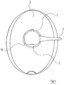
- FIG. 1 This shows in plan view the visible parts protruding from the wall a sanitary wall fitting, in the present case one Concealed thermostatic valves, namely a decorative cap 1, a volume control handle 2 and a temperature adjustment handle 3.
- the decorative cap 1 surrounds one in the drawing not shown neck area of the wall fitting. she penetrates a cover rosette, the total with the Reference numeral 4 marked and from that in Figure 1 only a decorative hood 5 can be seen.
- the cover rosette 4 is used in a known manner, the installation space for the Cover the wall fitting in the mounting wall on the outside.
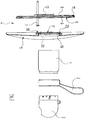
- FIG 2 shows an exploded view of the cover rosette 4 and the various elements of the wall fitting, which are visible in Figure 1.
- This figure 2 is closed remove that the cover rosette 4 except for the already mentioned hood 5 includes a cover plate 6.
- This Cover plate 6 is in a known manner on the outer surface the mounting wall spans the installation space for the parts of the wall fitting under plaster and is with screws 7 on the located in the installation space Attached housing area of the wall fitting.
- the decorative hood 5 is detachable in a manner on the cover plate 6 attached, where no fasteners visible are (Figure 1) and the following based on the figures 3 to 12 is described.
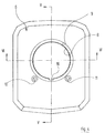
- the cover plate 6 is closer in Figures 4 to 6 shown. It has a through opening 8, whose diameter is larger by a certain amount than the outer diameter of the decorative hood 1. On the the side facing away from the mounting wall has the through opening 8 an enlarged area 9.
- a cylindrical collar 12 is formed on the side facing the mounting wall, i.e. in figure 5 on the right and in FIG. 6 on the upper side, is on the cover plate 6 coaxial to the through hole 8 .
- a circumferential groove 14 is also formed in the edge area, which the inclusion of an O-ring 15 (compare Figure 2) is used. The O-ring 15 seals in the assembly position the cover plate 6 against the outer surface of the Assembly wall from.
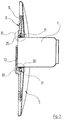
- FIG. 7 shows the decorative hood 5 in vertical section the cover rosette 4 and one attached to the decorative hood 5 Clamping ring 17, which in turn is the releasable Assembly of the decorative hood 5 and the clamping ring 17 Unit on the cover plate 6 is used.
- the decorative hood 5 also has a through opening 18, through which in the shown in Figure 3 Installation position extends the decorative cap 1 of the wall fitting.
- the diameter of this through hole 18 corresponds to the outer diameter of the decorative cap 1.
- Die Through opening 18 is of a cylindrical shape limited to the mounting wall extending neck 30. At angular intervals from each other are on the outer edge of the neck 30 formed several tabs 31, which in of the crimping with the Clamping ring 17 serve.
- the inner diameter of the clamping ring 17 is slight larger than the outer diameter of the decorative cap 1.
- a groove 20 molded, which the receiving an O-ring 21st (compare Figures 3, 11 and 12).
- O-ring 21st (compare Figures 3, 11 and 12).
- the Decorative hood 5 facing side has the through opening 18 of the clamping ring 17 enlarged an area 22 Diameter, which is the outer diameter of the neck 30 corresponds to the decorative hood 5.
- At certain angular intervals from each other are in the inner surface 19 of the clamping ring 17 also formed mounting recesses 23. These are in their upper, the decorative hood 5 facing Area provided with conical flanging surfaces 24, the with increasing distance from the axis of the clamping ring back away.
- molded elastic spring tabs 25 are also at certain angular intervals molded elastic spring tabs 25, the one in the direction of the decorative hood 5 pointing connection. section 25a and a wall thickness increased Have latching section 25b.
- the dimensioning of the spring tabs 25 is such that in the relaxed, in the figures 8 to 10 shown state the radially inner boundary surfaces 25c of the locking areas 25b on a circle lie, which is smaller than the outer diameter of the decorative cap 1 of the sanitary fitting is.
- the radially outer boundary surfaces 25d of the spring tabs 25 are also as locking surfaces trained and wear a variety parallel grooves. The bumps between these grooves have a diameter that is the diameter of between the grooves of the locking surface 13 of the cover plate 6 lying Corresponds to surveys.
- a positioning projection 26 is formed, which also away from the decorative hood 5, ie in the assembly position shows in the direction of the cover plate 6.
- the clamping ring 17 with the decorative hood is already factory-made 5 connected to the unit shown in FIG. 7, by the tabs 31 of the decorative hood 5 in the mounting recesses 23 of the clamping ring 27 inserted and there outwards via the inclined flanging surfaces 24 be pressed (compare in particular FIG. 12).
- the assembly of the cover rose 4 and the viewing elements 1, 2, 3 of the wall fitting on the mounting wall as follows (compare in particular Figures 2 and 3): First, the cover plate 6 using the screws 7 on the inside of the installation opening in the mounting wall screwed on the lying area of the valve body; the cover plate 6 then lies over this installation opening. Then the existing of decorative hood 5 and clamping ring 17 Unit pushed onto the cover plate 6.
- the positioning advantage 26 penetrates into the groove 16 of the Cover plate 6 and ensures that the angular orientation the decorative hood 5 opposite the cover plate 6 correct is.
- the volume control handle 2 and the temperature adjustment handle 3 the corresponding parts of the wall fitting are attached, which extend through the decorative cap 1 and are not specifically shown in the drawing.
- the cover rosette 4 should be removed from the mounting wall be, for example, to access the in the installation space part of the wall fitting located on the mounting wall to win, so are the handles in reverse order 3 and 2 to be removed from the wall fitting. Then will the decorative cap 1 axially from the clamping ring 17 and the decorative hood 5 pulled out. Feather due to its elasticity the spring tabs 25 of the clamping ring 17 back in their position shown in FIGS. 9 and 10, in which their locking structures on surface 25d are not more in engagement with the locking structures on the surface 13 of the cover plate 6 are.
- the spring tabs can this radial movement do not carry out internally, so that also in this If the decorative cap is inserted, the clamping ring and thus the hood can no longer be detached from the cover plate.
Abstract
Description
- Figur 1
- die Draufsicht auf eine Abdeck-Rosette mit den Sichtteilen der Wandarmatur in montiertem Zustand;
- Figur 2
- eine Explosionsansicht der Abdeck-Rosette von Figur 1 sowie der Sichtteile der Wandarmatur;
- Figur 3
- einen senkrechten Schnitt durch die Abdeck-Rosette von Figur 1 sowie die Zierkappe der Wandarmatur;
- Figur 4
- die Vorderansicht einer Abdeckplatte, die Teil der Abdeck-Rosette von Figur 1 ist;
- Figur 5
- einen Schnitt durch die Abdeckplatte von Figur 4 gemäß der dortigen Linie V-V;
- Figur 6
- einen Schnitt durch die Abdeckplatte von Figur 4 gemäß der dortigen Linie VI-VI;
- Figur 7
- einen vertikalen Schnitt durch die Zierhaube, die Teil der Abdeck-Rosette von Figur 1 ist, mit einem an dieser Zierhaube befestigten Klemmring;
- Figur 8
- in größerem Maßstab die Draufsicht auf den Klemmring von Figur 7;
- Figur 9
- einen Schnitt durch den Klemmring von Figur 8 gemäß der dortigen Linie IX-IX;
- Figur 10
- einen Schnitt durch den Klemmring von Figur 8 gemäß der dortigen Linie X-X ;
- Figur 11
- eine Ausschnittvergrößerung aus Figur 3 im Bereich des dortigen Kreises XI;
- Figur 12
- eine Ausschnittvergrößerung aus Figur 3 im Bereich des dortigen Kreises XII.
Claims (8)
- Abdeck-Rosette für eine sanitäre Unterputzarmatur mit einer an der Unterputzarmatur befestigbaren Abdeckplatte und einer lösbar an der Abdeckplatte befestigten Zierhaube, wobei Abdeckplatte und Zierhaube koaxiale Durchgangsöffnungen für einen Bereich der Unterputzarmatur aufweisen, auf den von außen her eine Zierkappe aufschiebbar ist,
dadurch gekennzeichnet, daß
an der Abdeckplatte (6) und/oder der Zierhaube (5) mindestens eine Federlasche (25) vorgesehen ist, deren zur Achse der Durchgangsöffnungen (8, 19) von Abdeckplatte (6) und Zierhaube (5) weisende Begrenzungsfläche (25c) in entspanntem Zustand auf einem zu den Durchgangsöffnungen (8, 19) konzentrischen Kreis liegt, dessen Durchmesser gleich dem oder kleiner als der Außendurchmesser der aufschiebbaren Zierkappe (1) ist, und die an der von der Achse der Durchgangsöffnung (8, 19) wegweisenden Begrenzungsfläche (25d) eine Rasteinrichtung aufweist, die mit einer komplementären Rasteinrichtung (30) am jeweils anderen Teil (Zierhaube (5) oder Abdeckplatte (6)) derart zusammenwirkt, daß sich bei aufgeschobener Zierkappe (1) die Rasteinrichtungen (25d, 30) nicht voneinander lösen lassen. - Abdeck-Rosette nach Anspruch 1, dadurch gekennzeichnet, daß die zur Achse der Durchgangsöffnungen (8, 19) weisende Begrenzungsfläche (25c) der Federlasche (25) in entspanntem Zustand auf einem Kreis liegt, dessen Durchmesser kleiner als der Außendurchmesser der aufzuschiebenden Zierkappe (1) ist, und daß diese Begrenzungsfläche (25c) ballig ausgebildet ist.
- Abdeck-Rosette nach Anspruch 1 oder 2, dadurch gekennzeichnet, daß die zur Achse der Durchgangsöffnungen (8, 19) weisende Begrenzungsfläche (25c) der Federlasche (25) in entspanntem Zustand auf einem Kreis liegt, dessen Durchmesser kleiner als der Außendurchmesser der Zierkappe (1) ist, und daß in entspanntem Zustand die zusammenwirkenden Rasteinrichtungen (25d, 30) nicht ineinander eingreifen.
- Abdeck-Rosette nach einem der vorhergehenden Ansprüche, dadurch gekennzeichnet, daß die zusammenwirkenden Rasteinrichtungen (25d, 30) durch eine Mehrzahl von auf einer zylindrischen Mantelfläche liegenden Rillen gebildet sind.
- Abdeck-Rosette nach einem der Ansprüche 1 bis 4, dadurch gekennzeichnet, daß eine Mehrzahl von Federlaschen (25) einstückig mit einem Klemmring (17) ausgebildet ist, die an der Abdeckplatte (6) oder der Zierhaube (5) befestigt ist.
- Abdeck-Rosette nach Anspruch 5, dadurch gekennzeichnet, daß die Zierhaube (5) an dem Klemmring (17) angebördelt ist.
- Abdeck-Rosette nach Anspruch 5 oder 6, dadurch gekennzeichnet, daß jede Federlasche (25) einen gekrümmten Übergangsbereich (25a) aufweist, der an seinem einen Ende an den Ringkörper des Klemmrings (17) angeformt ist und am anderen Ende mit einem Rastbereich (25) verbunden ist, der die relativ zur Achse der Durchgangsöffnungen (8, 19) weisende und die von der Achse der Durchgangsöffnungen (8, 19) weg weisende Begrenzungsfläche (25c, 25d) trägt.
- Abdeck-Rosette nach einem der Ansprüche 5 bis 7, dadurch gekennzeichnet, daß an der Innenmantelfläche des Klemmrings (17) eine Nut (20) ausgebildet ist, in welcher ein O-Ring (21) einliegt.
Applications Claiming Priority (2)
| Application Number | Priority Date | Filing Date | Title |
|---|---|---|---|
| DE19853950 | 1998-11-23 | ||
| DE19853950A DE19853950B4 (de) | 1998-11-23 | 1998-11-23 | Abdeck-Rosette |
Publications (3)
| Publication Number | Publication Date |
|---|---|
| EP1004711A2 true EP1004711A2 (de) | 2000-05-31 |
| EP1004711A3 EP1004711A3 (de) | 2000-08-23 |
| EP1004711B1 EP1004711B1 (de) | 2004-05-26 |
Family
ID=7888696
Family Applications (1)
| Application Number | Title | Priority Date | Filing Date |
|---|---|---|---|
| EP99118763A Expired - Lifetime EP1004711B1 (de) | 1998-11-23 | 1999-09-23 | Abdeck-Rosette |
Country Status (8)
| Country | Link |
|---|---|
| US (1) | US6178993B1 (de) |
| EP (1) | EP1004711B1 (de) |
| AT (1) | ATE267925T1 (de) |
| AU (1) | AU752476B2 (de) |
| CZ (1) | CZ296977B6 (de) |
| DE (2) | DE19853950B4 (de) |
| ES (1) | ES2221281T3 (de) |
| PL (1) | PL193692B1 (de) |
Cited By (3)
| Publication number | Priority date | Publication date | Assignee | Title |
|---|---|---|---|---|
| DE10219471B4 (de) * | 2002-04-30 | 2006-03-23 | Grohe Water Technology Ag & Co. Kg | Rosette |
| AT11547U3 (de) * | 2010-08-10 | 2011-04-15 | Josef Hoedl | Abdeckrosette |
| EP3162970A1 (de) * | 2015-10-28 | 2017-05-03 | Oras Oy | Abdeckrosette für eine sanitäre unterputzarmatur |
Families Citing this family (5)
| Publication number | Priority date | Publication date | Assignee | Title |
|---|---|---|---|---|
| DE19853951C2 (de) * | 1998-11-23 | 2002-09-05 | Hansa Metallwerke Ag | Abdeck-Rosette |
| US8261766B1 (en) * | 2009-10-25 | 2012-09-11 | Crescent Plumbing, Inc. | Positioning structure for assembly of a water faucet plaquette |
| US9534703B2 (en) * | 2014-02-18 | 2017-01-03 | Larry Holmes | Sink and shower handle restraint |
| PL126463U1 (pl) * | 2017-07-03 | 2019-01-14 | Przemysław Saczuk | Rozetka kostki WC |
| US11933417B2 (en) | 2019-09-27 | 2024-03-19 | Rain Bird Corporation | Irrigation sprinkler service valve |
Citations (1)
| Publication number | Priority date | Publication date | Assignee | Title |
|---|---|---|---|---|
| EP0485842B1 (de) | 1990-11-12 | 1995-09-27 | Friedrich Grohe Aktiengesellschaft | Rosette für Unterputz-Wasserarmaturen |
Family Cites Families (8)
| Publication number | Priority date | Publication date | Assignee | Title |
|---|---|---|---|---|
| JPS595152Y2 (ja) * | 1978-07-25 | 1984-02-16 | アイシン精機株式会社 | 集積型バルブセツト装置 |
| CH645706A5 (en) * | 1980-04-15 | 1984-10-15 | Similor Sa | Device for the connection between a sanitary unit and a water pipeline |
| DE3907587A1 (de) * | 1989-03-09 | 1990-09-13 | Grohe Armaturen Friedrich | Anschlussvorrichtung fuer wasserarmaturen |
| DE4034898C2 (de) * | 1990-11-02 | 1994-03-17 | Ideal Standard | Abdeckrosette für sanitäre Wasserarmaturen, insbesondere für Unterputzarmaturen |
| EP0593508B1 (de) * | 1991-07-05 | 1997-05-02 | Ideal-Standard Gmbh | Putzschablone für eine unterputzarmatur |
| US5263853A (en) * | 1991-12-04 | 1993-11-23 | Beth Pall | Safety device for a shower valve |
| JP2604717Y2 (ja) * | 1993-04-23 | 2000-06-05 | 千住スプリンクラー株式会社 | スプリンクラーヘッド用シーリングプレート |
| DE19702356A1 (de) * | 1997-01-23 | 1998-07-30 | Grohe Kg Hans | Sanitärarmatur mit einer Rosette |
-
1998
- 1998-11-23 DE DE19853950A patent/DE19853950B4/de not_active Expired - Fee Related
-
1999
- 1999-09-23 EP EP99118763A patent/EP1004711B1/de not_active Expired - Lifetime
- 1999-09-23 AT AT99118763T patent/ATE267925T1/de not_active IP Right Cessation
- 1999-09-23 ES ES99118763T patent/ES2221281T3/es not_active Expired - Lifetime
- 1999-09-23 DE DE59909576T patent/DE59909576D1/de not_active Expired - Lifetime
- 1999-11-11 AU AU59352/99A patent/AU752476B2/en not_active Ceased
- 1999-11-18 CZ CZ0409399A patent/CZ296977B6/cs not_active IP Right Cessation
- 1999-11-19 PL PL336652A patent/PL193692B1/pl not_active IP Right Cessation
- 1999-11-23 US US09/447,906 patent/US6178993B1/en not_active Expired - Fee Related
Patent Citations (1)
| Publication number | Priority date | Publication date | Assignee | Title |
|---|---|---|---|---|
| EP0485842B1 (de) | 1990-11-12 | 1995-09-27 | Friedrich Grohe Aktiengesellschaft | Rosette für Unterputz-Wasserarmaturen |
Cited By (3)
| Publication number | Priority date | Publication date | Assignee | Title |
|---|---|---|---|---|
| DE10219471B4 (de) * | 2002-04-30 | 2006-03-23 | Grohe Water Technology Ag & Co. Kg | Rosette |
| AT11547U3 (de) * | 2010-08-10 | 2011-04-15 | Josef Hoedl | Abdeckrosette |
| EP3162970A1 (de) * | 2015-10-28 | 2017-05-03 | Oras Oy | Abdeckrosette für eine sanitäre unterputzarmatur |
Also Published As
| Publication number | Publication date |
|---|---|
| EP1004711B1 (de) | 2004-05-26 |
| AU752476B2 (en) | 2002-09-19 |
| AU5935299A (en) | 2000-05-25 |
| CZ409399A3 (cs) | 2000-07-12 |
| US6178993B1 (en) | 2001-01-30 |
| PL193692B1 (pl) | 2007-03-30 |
| ATE267925T1 (de) | 2004-06-15 |
| DE59909576D1 (de) | 2004-07-01 |
| DE19853950B4 (de) | 2004-05-19 |
| CZ296977B6 (cs) | 2006-08-16 |
| EP1004711A3 (de) | 2000-08-23 |
| PL336652A1 (en) | 2000-06-05 |
| DE19853950A1 (de) | 2000-05-31 |
| ES2221281T3 (es) | 2004-12-16 |
Similar Documents
| Publication | Publication Date | Title |
|---|---|---|
| EP0485842B2 (de) | Rosette für Unterputz-Wasserarmaturen | |
| EP1845208B1 (de) | Installationseinrichtung für Sanitärelemente | |
| DE3843095C2 (de) | Befestigungseinrichtung für Verkleidungen | |
| EP2636803B1 (de) | Unterputzkasten mit Putzdickenausgleich | |
| CH697752B1 (de) | Zeitmesser. | |
| DE102008013736A1 (de) | Einbaukasten zum variablen Einbau von Sanitärarmaturen | |
| EP1004711B1 (de) | Abdeck-Rosette | |
| DE102013003823B4 (de) | Sanitärarmatur mit einer Rosette | |
| EP1004712B1 (de) | Abdeck-Rosette für den Anschlussbereich einer sanitären Wandarmatur | |
| DE19853951C2 (de) | Abdeck-Rosette | |
| EP0754827A2 (de) | Vorrichtung zur axial unverschieblichen, lösbaren Befestigung einer Handhabe an einem Lagerteil, insbesondere für Türdrücker, Fenstergriffe oder dgl. | |
| DE2920836A1 (de) | Halterung fuer lautsprecher in kraftfahrzeugen | |
| EP2369215A1 (de) | Steckverbindung | |
| DE4307776C1 (de) | Sanitäre Armatur | |
| DE4217529C2 (de) | Unterputzkasten für eine Sanitärarmatur | |
| DE3628473C2 (de) | Wandanschlußstück | |
| EP3045617B1 (de) | Rosette und anordnung eines tür- oder fensterdrückers und einer rosette an einer aufnahmeöffnung eines türblatts, eines fensterblatts oder dergleichen | |
| EP2853643A1 (de) | Anschlusskörper für eine sanitäre Unterputzarmatur | |
| DE3506121C2 (de) | ||
| AT412790B (de) | Abdeckrosette für eine sanitäre unterputzarmatur | |
| EP0730911A1 (de) | Handbrause | |
| EP0733746A2 (de) | Halter | |
| DE19602161A1 (de) | Sanitärarmatur | |
| DE8507823U1 (de) | Sanitärarmatur | |
| DE3509520A1 (de) | Sanitaerarmatur |
Legal Events
| Date | Code | Title | Description |
|---|---|---|---|
| PUAI | Public reference made under article 153(3) epc to a published international application that has entered the european phase |
Free format text: ORIGINAL CODE: 0009012 |
|
| AK | Designated contracting states |
Kind code of ref document: A2 Designated state(s): AT BE CH CY DE DK ES FI FR GB GR IE IT LI LU MC NL PT SE |
|
| AX | Request for extension of the european patent |
Free format text: AL;LT;LV;MK;RO;SI |
|
| PUAL | Search report despatched |
Free format text: ORIGINAL CODE: 0009013 |
|
| AK | Designated contracting states |
Kind code of ref document: A3 Designated state(s): AT BE CH CY DE DK ES FI FR GB GR IE IT LI LU MC NL PT SE |
|
| AX | Request for extension of the european patent |
Free format text: AL;LT;LV;MK;RO;SI |
|
| 17P | Request for examination filed |
Effective date: 20010130 |
|
| AKX | Designation fees paid |
Free format text: AT BE CH CY DE DK ES FI FR GB GR IE IT LI LU MC NL PT SE |
|
| GRAP | Despatch of communication of intention to grant a patent |
Free format text: ORIGINAL CODE: EPIDOSNIGR1 |
|
| GRAS | Grant fee paid |
Free format text: ORIGINAL CODE: EPIDOSNIGR3 |
|
| GRAA | (expected) grant |
Free format text: ORIGINAL CODE: 0009210 |
|
| AK | Designated contracting states |
Kind code of ref document: B1 Designated state(s): AT BE CH CY DE DK ES FI FR GB GR IE IT LI LU MC NL PT SE |
|
| PG25 | Lapsed in a contracting state [announced via postgrant information from national office to epo] |
Ref country code: IT Free format text: LAPSE BECAUSE OF FAILURE TO SUBMIT A TRANSLATION OF THE DESCRIPTION OR TO PAY THE FEE WITHIN THE PRESCRIBED TIME-LIMIT;WARNING: LAPSES OF ITALIAN PATENTS WITH EFFECTIVE DATE BEFORE 2007 MAY HAVE OCCURRED AT ANY TIME BEFORE 2007. THE CORRECT EFFECTIVE DATE MAY BE DIFFERENT FROM THE ONE RECORDED. Effective date: 20040526 Ref country code: IE Free format text: LAPSE BECAUSE OF FAILURE TO SUBMIT A TRANSLATION OF THE DESCRIPTION OR TO PAY THE FEE WITHIN THE PRESCRIBED TIME-LIMIT Effective date: 20040526 Ref country code: GB Free format text: LAPSE BECAUSE OF FAILURE TO SUBMIT A TRANSLATION OF THE DESCRIPTION OR TO PAY THE FEE WITHIN THE PRESCRIBED TIME-LIMIT Effective date: 20040526 Ref country code: FI Free format text: LAPSE BECAUSE OF FAILURE TO SUBMIT A TRANSLATION OF THE DESCRIPTION OR TO PAY THE FEE WITHIN THE PRESCRIBED TIME-LIMIT Effective date: 20040526 Ref country code: CY Free format text: LAPSE BECAUSE OF FAILURE TO SUBMIT A TRANSLATION OF THE DESCRIPTION OR TO PAY THE FEE WITHIN THE PRESCRIBED TIME-LIMIT Effective date: 20040526 |
|
| REG | Reference to a national code |
Ref country code: GB Ref legal event code: FG4D Free format text: NOT ENGLISH |
|
| REG | Reference to a national code |
Ref country code: CH Ref legal event code: EP |
|
| REG | Reference to a national code |
Ref country code: CH Ref legal event code: NV Representative=s name: FREI PATENTANWALTSBUERO Ref country code: IE Ref legal event code: FG4D Free format text: GERMAN |
|
| REF | Corresponds to: |
Ref document number: 59909576 Country of ref document: DE Date of ref document: 20040701 Kind code of ref document: P |
|
| PG25 | Lapsed in a contracting state [announced via postgrant information from national office to epo] |
Ref country code: SE Free format text: LAPSE BECAUSE OF FAILURE TO SUBMIT A TRANSLATION OF THE DESCRIPTION OR TO PAY THE FEE WITHIN THE PRESCRIBED TIME-LIMIT Effective date: 20040826 Ref country code: GR Free format text: LAPSE BECAUSE OF FAILURE TO SUBMIT A TRANSLATION OF THE DESCRIPTION OR TO PAY THE FEE WITHIN THE PRESCRIBED TIME-LIMIT Effective date: 20040826 Ref country code: DK Free format text: LAPSE BECAUSE OF FAILURE TO SUBMIT A TRANSLATION OF THE DESCRIPTION OR TO PAY THE FEE WITHIN THE PRESCRIBED TIME-LIMIT Effective date: 20040826 |
|
| PG25 | Lapsed in a contracting state [announced via postgrant information from national office to epo] |
Ref country code: LU Free format text: LAPSE BECAUSE OF NON-PAYMENT OF DUE FEES Effective date: 20040923 |
|
| PG25 | Lapsed in a contracting state [announced via postgrant information from national office to epo] |
Ref country code: MC Free format text: LAPSE BECAUSE OF NON-PAYMENT OF DUE FEES Effective date: 20040930 Ref country code: BE Free format text: LAPSE BECAUSE OF NON-PAYMENT OF DUE FEES Effective date: 20040930 |
|
| GBV | Gb: ep patent (uk) treated as always having been void in accordance with gb section 77(7)/1977 [no translation filed] |
Effective date: 20040526 |
|
| REG | Reference to a national code |
Ref country code: ES Ref legal event code: FG2A Ref document number: 2221281 Country of ref document: ES Kind code of ref document: T3 |
|
| REG | Reference to a national code |
Ref country code: IE Ref legal event code: FD4D |
|
| ET | Fr: translation filed | ||
| BERE | Be: lapsed |
Owner name: HANSA METALLWERKE A.G. Effective date: 20040930 |
|
| PLBE | No opposition filed within time limit |
Free format text: ORIGINAL CODE: 0009261 |
|
| STAA | Information on the status of an ep patent application or granted ep patent |
Free format text: STATUS: NO OPPOSITION FILED WITHIN TIME LIMIT |
|
| 26N | No opposition filed |
Effective date: 20050301 |
|
| BERE | Be: lapsed |
Owner name: *HANSA METALLWERKE A.G. Effective date: 20040930 |
|
| PG25 | Lapsed in a contracting state [announced via postgrant information from national office to epo] |
Ref country code: PT Free format text: LAPSE BECAUSE OF NON-PAYMENT OF DUE FEES Effective date: 20041026 |
|
| PGFP | Annual fee paid to national office [announced via postgrant information from national office to epo] |
Ref country code: ES Payment date: 20100329 Year of fee payment: 11 Ref country code: CH Payment date: 20100330 Year of fee payment: 11 |
|
| PGFP | Annual fee paid to national office [announced via postgrant information from national office to epo] |
Ref country code: AT Payment date: 20100331 Year of fee payment: 11 |
|
| PGFP | Annual fee paid to national office [announced via postgrant information from national office to epo] |
Ref country code: FR Payment date: 20100415 Year of fee payment: 11 |
|
| PGFP | Annual fee paid to national office [announced via postgrant information from national office to epo] |
Ref country code: NL Payment date: 20100330 Year of fee payment: 11 Ref country code: DE Payment date: 20100326 Year of fee payment: 11 |
|
| REG | Reference to a national code |
Ref country code: NL Ref legal event code: V1 Effective date: 20110401 |
|
| REG | Reference to a national code |
Ref country code: CH Ref legal event code: PL |
|
| REG | Reference to a national code |
Ref country code: FR Ref legal event code: ST Effective date: 20110531 |
|
| REG | Reference to a national code |
Ref country code: DE Ref legal event code: R119 Ref document number: 59909576 Country of ref document: DE Effective date: 20110401 |
|
| PG25 | Lapsed in a contracting state [announced via postgrant information from national office to epo] |
Ref country code: LI Free format text: LAPSE BECAUSE OF NON-PAYMENT OF DUE FEES Effective date: 20100930 Ref country code: FR Free format text: LAPSE BECAUSE OF NON-PAYMENT OF DUE FEES Effective date: 20100930 Ref country code: DE Free format text: LAPSE BECAUSE OF NON-PAYMENT OF DUE FEES Effective date: 20110401 Ref country code: CH Free format text: LAPSE BECAUSE OF NON-PAYMENT OF DUE FEES Effective date: 20100930 |
|
| PG25 | Lapsed in a contracting state [announced via postgrant information from national office to epo] |
Ref country code: NL Free format text: LAPSE BECAUSE OF NON-PAYMENT OF DUE FEES Effective date: 20110401 Ref country code: AT Free format text: LAPSE BECAUSE OF NON-PAYMENT OF DUE FEES Effective date: 20100923 |
|
| REG | Reference to a national code |
Ref country code: ES Ref legal event code: FD2A Effective date: 20111019 |
|
| PG25 | Lapsed in a contracting state [announced via postgrant information from national office to epo] |
Ref country code: ES Free format text: LAPSE BECAUSE OF NON-PAYMENT OF DUE FEES Effective date: 20100924 |