EP1005223A2 - A method for adjusting image detail to compensate for an applied tone scale - Google Patents
A method for adjusting image detail to compensate for an applied tone scale Download PDFInfo
- Publication number
- EP1005223A2 EP1005223A2 EP99203810A EP99203810A EP1005223A2 EP 1005223 A2 EP1005223 A2 EP 1005223A2 EP 99203810 A EP99203810 A EP 99203810A EP 99203810 A EP99203810 A EP 99203810A EP 1005223 A2 EP1005223 A2 EP 1005223A2
- Authority
- EP
- European Patent Office
- Prior art keywords
- tone scale
- signal
- image
- scale function
- detail
- Prior art date
- Legal status (The legal status is an assumption and is not a legal conclusion. Google has not performed a legal analysis and makes no representation as to the accuracy of the status listed.)
- Withdrawn
Links
Images


Classifications
-
- H—ELECTRICITY
- H04—ELECTRIC COMMUNICATION TECHNIQUE
- H04N—PICTORIAL COMMUNICATION, e.g. TELEVISION
- H04N1/00—Scanning, transmission or reproduction of documents or the like, e.g. facsimile transmission; Details thereof
- H04N1/46—Colour picture communication systems
- H04N1/56—Processing of colour picture signals
- H04N1/58—Edge or detail enhancement; Noise or error suppression, e.g. colour misregistration correction
-
- H—ELECTRICITY
- H04—ELECTRIC COMMUNICATION TECHNIQUE
- H04N—PICTORIAL COMMUNICATION, e.g. TELEVISION
- H04N1/00—Scanning, transmission or reproduction of documents or the like, e.g. facsimile transmission; Details thereof
- H04N1/40—Picture signal circuits
- H04N1/409—Edge or detail enhancement; Noise or error suppression
Definitions
- the invention relates generally to the field of digital image processing and, more particularly, to a method for modifying image detail to compensate for an applied tone scale or for the tonal characteristics of an output device.
- tone scale function modifies the amplitudes of high frequency detail information. This phenomenon occurs when the tone scale function is applied to each of the color channels independently, or when the tone scale function is applied to the luminance channel of a luminance-chrominance transformed digital image.
- the resultant image detail will also be adversely modified with respect to the original image.
- the tonal characteristics of an output device such as a display monitor and a digital printer, can have the same affect on image detail as an applied tone scale function.
- any spatial filtering operations designed to compensate for the device characteristics must be applied before the image is passed to the device.
- the prior art contains several examples which address the problem of detail distortion by tone scale application. Many of these examples utilize frequency decomposition methods in the application of the tone scale function.
- the present invention is directed to overcoming one or more of the problems set forth above.
- the invention resides in a method for modifying the spatial frequency detail of a digital image channel, the method comprising: (a) receiving a digital image channel; (b) providing a tone scale function; and (c) modifying the spatial frequency detail of the digital image channel based on the characteristics of the tone scale function.
- the present invention has the advantage of modifying the spatial frequency detail of a digital image to compensate for the effects of the application of a tone scale function.
- the tone scale function may be applied to the digital image either before or after the application of the present invention in an image processing chain. As a result of the application of the present invention, the digital image displayed on the final output medium will appear more natural than a similar image processed without the present invention.
- a digital image which is typically a two-dimensional array of red, green, and blue pixel values, or a single monochrome pixel value corresponding to light intensities.
- a digital representation of an image typically in RGB color space consisting of separate red, green, and blue image channels, is transformed to a luminance-chrominance color space by a color space matrix transformation resulting in a luminance image channel and two chrominance image channels.
- the present invention operates on only the luminance channel or individually on each chrominance channel, for example red, green and blue. This transformation into a luminance-chrominance is well known in the art.
- a digital image channel is input into a tone scale sensitive sharpener 10 where the image is divided into two portions by a pedestal splitter 30 ⁇ a pedestal signal and a texture signal, as will be described in detail below.
- the texture signal includes image high frequency information excluding the high frequency component of sharp edges, and the pedestal signal is the slowly varying signal except in the neighborhood of sharp edges.
- the texture multiplier generator 40 receives a user-defined tone scale function, and as illustrated in Fig. 3, calculates the local slope of the tone scale function evaluated at the value of the received pedestal signal.
- the tone scale function shown in Fig. 3 may be a tone scale function that is digitally applied, or may be the characteristic response of an input or output device.
- the texture multiplier generator 40 then transforms the calculated local slope into a texture multiplier value, as will be described in detail hereinbelow.
- the texture signal is an example of a spatial frequency detail signal.
- Another example of a spatial frequency detail signal that is simpler to compute is the highpass image signal.
- the multiplier 50 receives the texture signal and the texture multiplier value from the texture multiplier generator 40, and generates the product of the two signals. Multiplication of one signal by another signal is well known in the art, and will not be further discussed.
- the adder 60 receives the pedestal signal from the pedestal splitter 30 and the signal output of the multiplier 50, and adds the two signals for forming a transformed image channel. Addition of two signals is well known in the art and will not be further discussed.
- the signal output from the adder 60 is the transformed digital image channel.
- the transformed digital image channel is input into the tone scale applicator 20 that applies the tone scale function, such that the application of the expected tone scale will not significantly alter the detail of the image as compared with the original image.
- the digital image channel input into the pedestal splitter 30 is split into a highpass signal and a lowpass signal by spatial filtering procedure performed by a frequency splitter 70.
- the frequency splitter 70 uses well-known convolution to convolve the digital image channel with a digital filter, as will be described below.
- the convolved signal is the lowpass signal.
- the frequency splitter 70 then creates the highpass signal by subtracting the lowpass signal from the original image channel.
- the digital filter is a Gaussian filter with a standard deviation (sigma) of 2.5 pixels. The preferred value of the standard deviation of the Gaussian filter may vary with image size.
- the pedestal generator 100 receives the original image channel and the texture signal and subtracts the texture signal from the original image channel, which produces a pedestal signal.
- Anon-linear spatial filter herein described shall be defined as a spatial filter which can not be described by the linear spatial filter equation.
- the output of applying a generalized control signal to an input signal bears a multiplicative relationship to the input signal.
- y ij a ij x ij , where the x ij values represent the input signal ij th pixel values and the a ij values represent the ij th pixel values of the control signal.
- the result of applying a control signal to an input signal falls into the general category of a non-linear spatial filter if the control signal is derived from a spatial filtered version of the input signal.
- the avoidance signal a ( x ) is an example of a control signal created from a spatially filtered version of the digital image channel.
- the texture signal q ( x ) described in the preferred embodiment is an example of a non-liner spatial filter produced with the application of a control signal to the highpass signal.
- the avoidance signal generator 80 there is illustrated an exploded block diagram of the avoidance signal generator 80.
- the low pass signal is input into a non-directional squared gradient calculator 110 for producing a non-directional gradient signal.
- This calculation is performed by first calculating the difference between the pixel and its upper vertical neighbor, as well as the difference between the pixel and its horizontal neighbor to the right.
- the non-directional squared gradient is the sum of the squares of these two differences.
- the non-directional squared gradient signal is then mapped by an artifact avoidance function applicator 120 to produce an artifact avoidance signal as the output of the avoidance signal generator 80.
- This output signal of the avoidance signal generator 80 will from now on be referred to as a ( x ).
- this mapping function is performed by passing the non-directional squared gradient signal, ndg ( x ), through an artifact avoidance function av () formed in the following manner.
- the preferred values for C o and C 1 will vary according to the range of the input data.
- the input data range in the images used in the development of this preferred embodiment ranged from 0 to 4095.
- the preferred value for C o is 148
- the preferred value for C 1 is 1300.
- av ( y ) 1 - sqrt (( y - C o ) /( C 1 - C o ))
- av ( y ) 1 for y ⁇ C o
- av ( y ) 0 for y > C 1 .
- the artifact avoidance function is most efficiently implemented as a look-up-table (LUT).
- Fig. 6 therein is illustrated an exploded view of the texture multiplier generator 40.
- the user-defined tone scale function f ( x ) and the pedestal signal p ( x ) are applied to the inputs of the slope calculator 130.
- the slope calculator 130 evaluates the slope of the tone scale function at the value of the pedestal signal.
- the slope calculator 130 may then index into such a LUT with the value of the pedestal signal in order to derive the local slope of the tone scale function.
- the value of the slope output from the slope calculator 130 is input to the texture factor calculator 140.
- the texture factor calculator 140 converts the slope from the slope calculator 130 into the texture multiplier factor by which the texture signal will be scaled with the multiplier 50 in Fig. 2.
- the digital image signal is passed through a frequency splitter 70, creating a lowpass signal and a highpass signal from the original digital image channel.
- the lowpass signal is then passed though the avoidance signal generator 80 in order to generate the artifact avoidance signal.
- the lowpass signal and tone scale function f ( x ) are passed into the slope multiplier generator 40b, which performs substantially the same operation as the texture multiplier generator 40 previously described hereinabove.
- the slope calculator 130 evaluates the slope at the value of the lowpass signal rather than the pedestal signal value.
- the texture signal output from the slope multiplier generator 40b then is multiplied by a multiplier 50c with the product of the multiplier 50a of the avoidance signal and the highpass signal.
- the product so formed is applied to the input of the adder 60.
- the lowpass signal is also applied to the input of the adder 60 as well as the output of multiplier 50b which formed the product of the highpass signal and (1 - a ( x )).
- the output of the adder 60 is a processed image channel in which texture content has been adjusted to compensate for the application of a tone scale function to the processed image.
- the output of the adder 60 is very similar to the output of the preferred embodiment of the present invention.
- the input to the tone scale sensitive sharpener 10 is the tone scaled image channel that was output from the tone scale function applicator 20.
- a mathematical analysis of the present invention may be used to show the operation of the present invention in regions of the image where the a ( x ) signal is 1, and regions of the image where the a ( x ) is 0.
- the present invention is shown to be nearly equivalent in each case. Those skilled in the art will realize that there exist many possible embodiments that result in equivalent operation to the present invention when analyzed by the following method.
- the artifact avoidance signal a ( x ) is 1 for pixels in regions of the image which are generally flat.
- the signal a ( x ) becomes 0 for pixels in regions of the image that contain high transition edges.
- the signal a ( x ) may take on any value within the range of 0.0 to 1.0 depending upon the structure of the local region of the image.
- the processed pixel will be bounded by f ( x ) and f ( g ( x )) + h ( x ).
- the method of the current invention allows an image to be preprocessed in anticipation of a specific tone scale function.
- the image is sharpened with a gain factor related to the inverse of the local slope of the tone scale function, except in those regions of the image where sharpening of the detail would produce unnatural artifacts.
- the tone scale function is applied to the processed image, the detail of the resultant image will be similar to the detail of the original image.
- t ( x ) g ( x ) + [1 - a ( x )] h ( x ) + a ( x )( h ( x ))/ f '( g ( x )).
- the digital image is preferably transformed back into RGB color space by an inverse color space matrix transformation for permitting printing a hardcopy or displaying on an output device.
Abstract
Description
- The invention relates generally to the field of digital image processing and, more particularly, to a method for modifying image detail to compensate for an applied tone scale or for the tonal characteristics of an output device.
- Traditional methods of applying a tone scale function to a digital image modify the apparent sharpness of the image because the tone scale modifies the amplitudes of high frequency detail information. This phenomenon occurs when the tone scale function is applied to each of the color channels independently, or when the tone scale function is applied to the luminance channel of a luminance-chrominance transformed digital image.
- For systems in which the spatial filtering step must precede the application of a tone scale function, the resultant image detail will also be adversely modified with respect to the original image. The tonal characteristics of an output device, such as a display monitor and a digital printer, can have the same affect on image detail as an applied tone scale function. For these applications, any spatial filtering operations designed to compensate for the device characteristics must be applied before the image is passed to the device.
- The prior art contains several examples which address the problem of detail distortion by tone scale application. Many of these examples utilize frequency decomposition methods in the application of the tone scale function.
- For example, to apply a tone scale function to a digital image without distorting the detail information, in U.S. Patent No. 5,012,333, Lee et al. proposed separating the image into a high frequency and a low frequency image by using FIR filters. The tone scale function is then applied to only the low frequency image, and the high frequency image is added back to the tone scaled low frequency image. Also, in U.S. Patent No. 5,454,044 Nakajima suggests modifying the image contrast by the formula
- In addition, methods exist in the prior art to improve the detail of a digital image. These methods often utilize unsharp masking, which is well known in the art. Examples exist in the prior art that modify parameters of the unsharp masking adaptively while processing the digital image. For example, in U.S. Patent No. 5,081,692, Kwon et al describes a method of modifying the gain of an unsharp mask based upon a local center weighted variance. However, none of the prior art methods of sharpening a digital image compensate specifically for the degradation to the image detail that is induced by an applied tone scale function.
- In addition, it is well know in the art that various sharpening algorithms may be used to compensate for the loss of spatial detail due to blurring when printing or displaying an image on an output device. This method includes tailoring the sharpening to the spatial characteristics of the output device. However, it would also be beneficial to tailor the level of sharpening to the tonal response of the device as well.
- All methods described in the prior art designed to modify the spatial detail in relation to a tone scale function are methods of tone scale function application. As such, the detail of the original image input to the tone scale function application algorithm has not yet been undesirably altered. The goal of these methods is the application of a tone scale function without damaging image detail. For applications in which a tone scale function has already been applied to an image the image detail has likewise already been modified. Thus the methods described in the prior art are not applicable to overcoming this shortcoming.
- Consequently, a need exists for overcoming the above-described drawbacks. More specifically, a need exists for a method of restoring image spatial detail in an image processing step occurring after the application of a tone scale function. Also, a need exists for a method of modifying the image spatial detail in preparation for the anticipated application of a tone scale function.
- The present invention is directed to overcoming one or more of the problems set forth above. Briefly summarized, according to one aspect of the present invention, the invention resides in a method for modifying the spatial frequency detail of a digital image channel, the method comprising: (a) receiving a digital image channel; (b) providing a tone scale function; and (c) modifying the spatial frequency detail of the digital image channel based on the characteristics of the tone scale function.
- These and other aspects, objects, features and advantages of the present invention will be more clearly understood and appreciated from a review of the following detailed description of the preferred embodiments and appended claims, and by reference to the accompanying drawings.
- The present invention has the advantage of modifying the spatial frequency detail of a digital image to compensate for the effects of the application of a tone scale function. The tone scale function may be applied to the digital image either before or after the application of the present invention in an image processing chain. As a result of the application of the present invention, the digital image displayed on the final output medium will appear more natural than a similar image processed without the present invention.
-
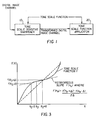
- Fig. 1 is a block diagram illustrating an overview of the present invention;
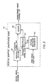
- Fig. 2 is an exploded view of the tone scale sensitive sharpener of Fig. 1;
- Fig. 3 is an illustration of a typical tone scale function;
- Fig. 4 is an exploded view of the pedestal splitter of Fig. 2;
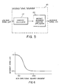
- Fig. 5 is an exploded view of the avoidance signal generator of Fig. 4;
- Fig. 6 is an illustration of an artifact avoidance function;
- Fig. 7 is an exploded view of the texture multiplier generator of Fig. 2;
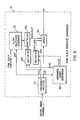
- Fig. 8 is an alternative embodiment of the present invention; and,
- Fig. 9 is an alternative embodiment of Fig. 1.
-
- In the following description, the present invention will be described in the preferred embodiment as a software program. Those skilled in the art will readily recognize that the equivalent of such software may also be constructed in hardware.
- Referring to Fig. 1, there is illustrated an overview of the present invention. Before discussing Fig. 1, it is instructive to note that the present invention utilizes a digital image which is typically a two-dimensional array of red, green, and blue pixel values, or a single monochrome pixel value corresponding to light intensities. In this regard, a digital representation of an image, typically in RGB color space consisting of separate red, green, and blue image channels, is transformed to a luminance-chrominance color space by a color space matrix transformation resulting in a luminance image channel and two chrominance image channels. It facilitates understanding to note that the present invention operates on only the luminance channel or individually on each chrominance channel, for example red, green and blue. This transformation into a luminance-chrominance is well known in the art.
- Referring to Figs. 1 and 2, a digital image channel is input into a tone scale sensitive sharpener 10 where the image is divided into two portions by a pedestal splitter 30 ― a pedestal signal and a texture signal, as will be described in detail below. The texture signal includes image high frequency information excluding the high frequency component of sharp edges, and the pedestal signal is the slowly varying signal except in the neighborhood of sharp edges. The texture multiplier generator 40 receives a user-defined tone scale function, and as illustrated in Fig. 3, calculates the local slope of the tone scale function evaluated at the value of the received pedestal signal. The tone scale function. shown in Fig. 3 may be a tone scale function that is digitally applied, or may be the characteristic response of an input or output device. The texture multiplier generator 40 then transforms the calculated local slope into a texture multiplier value, as will be described in detail hereinbelow.
- The texture signal is an example of a spatial frequency detail signal. Another example of a spatial frequency detail signal that is simpler to compute is the highpass image signal.
- Referring back to Figs. 1 and 2, the multiplier 50 receives the texture signal and the texture multiplier value from the texture multiplier generator 40, and generates the product of the two signals. Multiplication of one signal by another signal is well known in the art, and will not be further discussed. The adder 60 receives the pedestal signal from the pedestal splitter 30 and the signal output of the multiplier 50, and adds the two signals for forming a transformed image channel. Addition of two signals is well known in the art and will not be further discussed.
- The signal output from the adder 60 is the transformed digital image channel. As shown in Fig. 1, the transformed digital image channel is input into the tone scale applicator 20 that applies the tone scale function, such that the application of the expected tone scale will not significantly alter the detail of the image as compared with the original image.
- Referring to Fig. 4, an exploded diagram of the pedestal splitter is shown. The digital image channel input into the pedestal splitter 30 is split into a highpass signal and a lowpass signal by spatial filtering procedure performed by a frequency splitter 70. The frequency splitter 70 uses well-known convolution to convolve the digital image channel with a digital filter, as will be described below. The convolved signal is the lowpass signal. The frequency splitter 70 then creates the highpass signal by subtracting the lowpass signal from the original image channel. Preferably, the digital filter is a Gaussian filter with a standard deviation (sigma) of 2.5 pixels. The preferred value of the standard deviation of the Gaussian filter may vary with image size. The value of 2.5 pixels for the sigma value was derived by optimizing the present invention with 1024 by 1536 pixel size images. This Gaussian filter is a two dimensional circularly symmetric low-pass filter whose filter coefficients may be derived by the following formula which is well known in the art:
- G(i, j) = the Gaussian filter coefficient at the (i, j) th pixel
- Sigma = the standard deviation of the Gaussian filter (2.5)
- π = the constant approximately 3.1415. . . The lowpass signal is input into an avoidance signal generator 80 for forming an avoidance signal, as will be described in detail below. A texture signal generator 90 receives both the highpass signal and the avoidance signal and both signals are multiplied therein for producing a texture signal.
-
- The pedestal generator 100 receives the original image channel and the texture signal and subtracts the texture signal from the original image channel, which produces a pedestal signal.
- A generalized linear spatial filter is described by the equation
- Referring to Fig. 5, there is illustrated an exploded block diagram of the avoidance signal generator 80. In this regard, the low pass signal is input into a non-directional squared gradient calculator 110 for producing a non-directional gradient signal. This calculation is performed by first calculating the difference between the pixel and its upper vertical neighbor, as well as the difference between the pixel and its horizontal neighbor to the right. The non-directional squared gradient is the sum of the squares of these two differences. The non-directional squared gradient signal is then mapped by an artifact avoidance function applicator 120 to produce an artifact avoidance signal as the output of the avoidance signal generator 80. This output signal of the avoidance signal generator 80 will from now on be referred to as a(x).
- Referring to Fig. 6, this mapping function is performed by passing the non-directional squared gradient signal, ndg(x), through an artifact avoidance function av() formed in the following manner. The preferred embodiment of the present invention utilizes an artifact avoidance function defined by:
- The preferred values for Co and C 1 will vary according to the range of the input data. The input data range in the images used in the development of this preferred embodiment ranged from 0 to 4095. In this case, the preferred value for Co is 148, and the preferred value for C 1 is 1300. As an alternate method for constructing the artifact avoidance function is described in the following equation:
- Those skilled in the art will realize that the artifact avoidance function av(x) may realize many forms. Performance of the present invention does not depend upon a specific equation for av(x).
- Still referring to Fig. 5, the artifact avoidance signal, a(x), is generated by the artifact avoidance function applicator 120. This is accomplished by applying the artifact avoidance function av(x), to the non-directional gradient signal ndg(x). The mathematical result is described by the equation:
- Referring to Fig. 6, therein is illustrated an exploded view of the texture multiplier generator 40. The user-defined tone scale function f(x) and the pedestal signal p(x) are applied to the inputs of the slope calculator 130. The slope calculator 130 evaluates the slope of the tone scale function at the value of the pedestal signal. The slope of the tone scale may be calculated with the following equation:
- Again referring to Fig. 7, the value of the slope output from the slope calculator 130 is input to the texture factor calculator 140. The texture factor calculator 140 converts the slope from the slope calculator 130 into the texture multiplier factor by which the texture signal will be scaled with the multiplier 50 in Fig. 2. The general form of the equation used to convert the slope to the texture factor is:
- tf(x) = texture factor
- B = normalization factor
- f'() = local slope of tone scale function output from slope calculator 130 The B variable is typically set to 1.0, however values other than one may be used in cases where the desire is to either decrease or increase the overall gain to the detail signal of the image after the application of the tone scale function.
-
- Referring to Fig. 8, there is illustrated an alternative configuration of the present invention. In this configuration, the digital image signal is passed through a frequency splitter 70, creating a lowpass signal and a highpass signal from the original digital image channel. In this regard, the lowpass signal is then passed though the avoidance signal generator 80 in order to generate the artifact avoidance signal. The lowpass signal and tone scale function f(x) are passed into the slope multiplier generator 40b, which performs substantially the same operation as the texture multiplier generator 40 previously described hereinabove. In this case, the exception is that the slope calculator 130 evaluates the slope at the value of the lowpass signal rather than the pedestal signal value. The texture signal output from the slope multiplier generator 40b then is multiplied by a multiplier 50c with the product of the multiplier 50a of the avoidance signal and the highpass signal. The product so formed is applied to the input of the adder 60. Also applied to the input of the adder 60 is the lowpass signal as well as the output of multiplier 50b which formed the product of the highpass signal and (1 - a(x)). The output of the adder 60 is a processed image channel in which texture content has been adjusted to compensate for the application of a tone scale function to the processed image. The output of the adder 60 is very similar to the output of the preferred embodiment of the present invention.
- Referring to Fig. 9, there is illustrated an alternative embodiment of the present invention. In this embodiment, the input to the tone scale sensitive sharpener 10 is the tone scaled image channel that was output from the tone scale function applicator 20.
- The final processed pixel of the preferred embodiment may also be represented in functional form:
- x = the input image channel
- t(x) = transformed digital image channel
- g(x) = a low-pass filtered version of x
- h(x) = a high-pass filtered version of x . i.e.
- f'(x) = slope of the tone scale function, evaluated at x
- a(x) = the artifact avoidance signal (the control signal)
-
- A mathematical analysis of the present invention may be used to show the operation of the present invention in regions of the image where the a(x) signal is 1, and regions of the image where the a(x) is 0. By analyzing the preferred embodiment and the alternative embodiment, the present invention is shown to be nearly equivalent in each case. Those skilled in the art will realize that there exist many possible embodiments that result in equivalent operation to the present invention when analyzed by the following method.
- The artifact avoidance signal a(x) is 1 for pixels in regions of the image which are generally flat. The signal a(x) becomes 0 for pixels in regions of the image that contain high transition edges. The signal a(x) may take on any value within the range of 0.0 to 1.0 depending upon the structure of the local region of the image.
- At this point, it becomes useful to make several approximations. The first is that with the nearly liner tone scale functions which are common to image processing,
- Secondly, in the case where a tone scale f(x) is applied to a signal x, the result is approximately:
- The third approximation follows directly from the first and second approximations.
- Thus, if the equation summarizing the preferred embodiment is evaluated with the three approximations, the resulting approximation for the output pixel value in relatively flat regions (
- For pixels with an intermediate a(x), (0 < a(x) < 1), the processed pixel will be bounded by f(x) and f(g(x)) + h(x).
- In summary, the method of the current invention allows an image to be preprocessed in anticipation of a specific tone scale function. The image is sharpened with a gain factor related to the inverse of the local slope of the tone scale function, except in those regions of the image where sharpening of the detail would produce unnatural artifacts. When the tone scale function is applied to the processed image, the detail of the resultant image will be similar to the detail of the original image.
- Many other flow diagrams may be constructed which will produce a result that, when evaluated with the three approximations, will be:
- For example, the alternative embodiment shown in Fig. 8 may be written algebraically from the flow diagram as:
- After the present invention performs its operations, the digital image is preferably transformed back into RGB color space by an inverse color space matrix transformation for permitting printing a hardcopy or displaying on an output device.
- Other aspects of the invention include:
- 1. The method wherein the step of modifying the spatial frequency detail of the digital image channel based on the characteristics of the tone scale function includes using a control signal to modify the spatial frequency detail.
- 2. The method wherein the step of modifying the spatial frequency detail of the digital image channel based on the characteristics of the tone scale function includes using a control signal to modify the spatial frequency detail.
- 3. The method further comprising extracting the spatial frequency detail from the digital image, channel.
- 4. The method further comprising extracting the spatial frequency detail from the digital image channel.
- 5. The method wherein the modification of the spatial frequency detail is proportional to the inverse of the slope of the tone scale function.
- 6. The method wherein the modification of the spatial frequency detail is proportional to the inverse of the slope of the tone scale function.
- 7. The method wherein the modification of the spatial frequency detail is proportional to the inverse of the slope of the tone scale function.
- 8. The method wherein the modification of the spatial frequency detail is proportional to the inverse of the slope of the tone scale function.
- 9. The method wherein the modification of the spatial frequency detail is proportional to the inverse of the slope of the tone scale function.
- 10. The method wherein the modification of the spatial frequency detail is proportional to the inverse of the slope of the tone scale function.
- 11. The method wherein the modification of the spatial frequency detail is proportional to the inverse of the slope of the tone scale function.
- 12. The method wherein the modification of the spatial frequency detail is proportional to the inverse of the slope of the tone scale function.
-
Claims (10)
- A method for modifying the spatial frequency detail of a digital image channel, the method comprising:(a) receiving a digital image channel;(b) providing a tone scale function; and,(c) modifying the spatial frequency detail of the digital image channel based on the characteristics of the tone scale function.
- The method as in claim 1, wherein step (a) includes receiving the digital image channel having the tone scale function applied to the digital image channel.
- The method as in claim 1 further comprising the step of applying the tone scale function after step (c).
- The method as in claim 3 further comprising the step of applying a tone scale function approximating the characteristic tonal response of a device.
- The method as in claim 1, wherein step (c) includes using a control signal to modify the spatial frequency detail.
- The method as in claim 2, wherein step (c) includes using a control signal to modify the spatial frequency detail.
- The method as in claim 6 further comprising extracting the spatial frequency detail from the digital image channel.
- The method as in claim 1, wherein the step of modifying of the spatial frequency detail is proportional to the inverse of the slope of the tone scale function.
- The method as in claim 2 wherein the modification of the spatial frequency detail is proportional to the inverse of the slope of the tone scale function.
- The method as in claim 3 wherein the modification of the spatial frequency detail is proportional to the inverse of the slope of the tone scale function.
Applications Claiming Priority (2)
| Application Number | Priority Date | Filing Date | Title |
|---|---|---|---|
| US199510 | 1988-05-27 | ||
| US09/199,510 US6167165A (en) | 1998-11-25 | 1998-11-25 | Method for adjusting image detail to compensate for an applied tone scale |
Publications (2)
| Publication Number | Publication Date |
|---|---|
| EP1005223A2 true EP1005223A2 (en) | 2000-05-31 |
| EP1005223A3 EP1005223A3 (en) | 2002-10-09 |
Family
ID=22737837
Family Applications (1)
| Application Number | Title | Priority Date | Filing Date |
|---|---|---|---|
| EP99203810A Withdrawn EP1005223A3 (en) | 1998-11-25 | 1999-11-15 | A method for adjusting image detail to compensate for an applied tone scale |
Country Status (3)
| Country | Link |
|---|---|
| US (1) | US6167165A (en) |
| EP (1) | EP1005223A3 (en) |
| JP (1) | JP2000187728A (en) |
Cited By (3)
| Publication number | Priority date | Publication date | Assignee | Title |
|---|---|---|---|---|
| EP1413985A2 (en) * | 2002-10-25 | 2004-04-28 | Eastman Kodak Company | Enhancing the tonal, spatial, and color characteristics of digital images using expansive and compressive tone scale functions |
| US7076111B2 (en) | 2000-11-30 | 2006-07-11 | Canon Kabushiki Kaisha | Image processing apparatus, image processing method, storage medium, and program |
| US7079700B2 (en) | 2000-11-30 | 2006-07-18 | Canon Kabushiki Kaisha | Image processing apparatus, image processing method, storage medium, and program |
Families Citing this family (21)
| Publication number | Priority date | Publication date | Assignee | Title |
|---|---|---|---|---|
| US6438264B1 (en) * | 1998-12-31 | 2002-08-20 | Eastman Kodak Company | Method for compensating image color when adjusting the contrast of a digital color image |
| US6549678B1 (en) * | 1999-01-29 | 2003-04-15 | Eastman Kodak Company | Method for preserving spatial detail when applying a multidimensional tonal transform to a digital color image |
| US6580835B1 (en) * | 1999-06-02 | 2003-06-17 | Eastman Kodak Company | Method for enhancing the edge contrast of a digital image |
| EP1374560A2 (en) * | 2001-03-30 | 2004-01-02 | Kodak Polychrome Graphics | Automated sharpening of images for soft proofing |
| ATE491984T1 (en) * | 2002-02-06 | 2011-01-15 | Soundtouch Ltd | METHOD FOR A TOUCH PAD |
| FR2841022B1 (en) * | 2002-06-12 | 2004-08-27 | Centre Nat Rech Scient | METHOD FOR LOCATING AN IMPACT ON A SURFACE AND DEVICE FOR IMPLEMENTING SAID METHOD |
| US7228004B2 (en) * | 2002-09-05 | 2007-06-05 | Eastman Kodak Company | Method for sharpening a digital image |
| US7043090B2 (en) | 2002-10-02 | 2006-05-09 | Eastman Kodak Company | Enhancing the tonal characteristics of digital images using expansive and compressive tone scale functions |
| US7130485B2 (en) * | 2002-10-02 | 2006-10-31 | Eastman Kodak Company | Enhancing the tonal and color characteristics of digital images using expansive and compressive tone scale functions |
| US7116838B2 (en) * | 2002-10-25 | 2006-10-03 | Eastman Kodak Company | Enhancing the tonal and spatial characteristics of digital images using selective spatial filters |
| US7280703B2 (en) * | 2002-11-14 | 2007-10-09 | Eastman Kodak Company | Method of spatially filtering a digital image using chrominance information |
| US7266229B2 (en) * | 2003-07-24 | 2007-09-04 | Carestream Health, Inc. | Method for rendering digital radiographic images for display based on independent control of fundamental image quality parameters |
| US7245781B2 (en) * | 2003-10-23 | 2007-07-17 | Eastman Kodak Companny | Applying a tone scale function to a digital image |
| US7269300B2 (en) * | 2003-10-24 | 2007-09-11 | Eastman Kodak Company | Sharpening a digital image in accordance with magnification values |
| US7558433B1 (en) | 2003-12-30 | 2009-07-07 | Adobe Systems Incorporated | Healing by texture synthesis in differential space |
| JP4538358B2 (en) * | 2005-03-30 | 2010-09-08 | パイオニア株式会社 | Image processing device |
| TW201001334A (en) * | 2008-06-20 | 2010-01-01 | Altek Corp | Adjustment method of color tone for digital image and electronic apparatus thereof |
| CN101621608B (en) * | 2008-07-04 | 2012-09-19 | 华晶科技股份有限公司 | Hue adjusting method of digital image and electronic device thereof |
| US20100002145A1 (en) * | 2008-07-07 | 2010-01-07 | Spence John P | Adaptive optimization of a video signal |
| US9129388B2 (en) | 2012-11-21 | 2015-09-08 | Apple Inc. | Global approximation to spatially varying tone mapping operators |
| US9646366B2 (en) * | 2012-11-30 | 2017-05-09 | Change Healthcare Llc | Method and apparatus for enhancing medical images |
Citations (6)
| Publication number | Priority date | Publication date | Assignee | Title |
|---|---|---|---|---|
| US5012333A (en) * | 1989-01-05 | 1991-04-30 | Eastman Kodak Company | Interactive dynamic range adjustment system for printing digital images |
| US5081692A (en) * | 1991-04-04 | 1992-01-14 | Eastman Kodak Company | Unsharp masking using center weighted local variance for image sharpening and noise suppression |
| DE4126751A1 (en) * | 1991-08-13 | 1993-02-04 | Agfa Gevaert Ag | Automatic image density correction for copier - using high pass signal derived from luminance signal to generate statistical frequency distribution for control of copy density signals |
| JPH07245709A (en) * | 1994-01-14 | 1995-09-19 | Ricoh Co Ltd | Method and device for processing picture signal |
| US5550888A (en) * | 1994-05-06 | 1996-08-27 | U.S. Philips Corporation | Method of displaying notably a digital X-ray image as a visible image, and device for carrying out the method |
| EP0849940A2 (en) * | 1996-12-18 | 1998-06-24 | Fujitsu Limited | An apparatus for converting gray levels of an image, a method thereof, a program storage device thereof, and an infrared camera |
Family Cites Families (3)
| Publication number | Priority date | Publication date | Assignee | Title |
|---|---|---|---|---|
| JP2663189B2 (en) * | 1990-01-29 | 1997-10-15 | 富士写真フイルム株式会社 | Image dynamic range compression processing method |
| US5341228A (en) * | 1990-12-04 | 1994-08-23 | Research Corporation Technologies | Method and apparatus for halftone rendering of a gray scale image using a blue noise mask |
| JP3359390B2 (en) * | 1993-09-27 | 2002-12-24 | 株式会社リコー | Spatial filter device |
-
1998
- 1998-11-25 US US09/199,510 patent/US6167165A/en not_active Expired - Lifetime
-
1999
- 1999-11-15 EP EP99203810A patent/EP1005223A3/en not_active Withdrawn
- 1999-11-24 JP JP11333359A patent/JP2000187728A/en active Pending
Patent Citations (6)
| Publication number | Priority date | Publication date | Assignee | Title |
|---|---|---|---|---|
| US5012333A (en) * | 1989-01-05 | 1991-04-30 | Eastman Kodak Company | Interactive dynamic range adjustment system for printing digital images |
| US5081692A (en) * | 1991-04-04 | 1992-01-14 | Eastman Kodak Company | Unsharp masking using center weighted local variance for image sharpening and noise suppression |
| DE4126751A1 (en) * | 1991-08-13 | 1993-02-04 | Agfa Gevaert Ag | Automatic image density correction for copier - using high pass signal derived from luminance signal to generate statistical frequency distribution for control of copy density signals |
| JPH07245709A (en) * | 1994-01-14 | 1995-09-19 | Ricoh Co Ltd | Method and device for processing picture signal |
| US5550888A (en) * | 1994-05-06 | 1996-08-27 | U.S. Philips Corporation | Method of displaying notably a digital X-ray image as a visible image, and device for carrying out the method |
| EP0849940A2 (en) * | 1996-12-18 | 1998-06-24 | Fujitsu Limited | An apparatus for converting gray levels of an image, a method thereof, a program storage device thereof, and an infrared camera |
Non-Patent Citations (1)
| Title |
|---|
| PATENT ABSTRACTS OF JAPAN vol. 1996, no. 01, 31 January 1996 (1996-01-31) & JP 07 245709 A (RICOH CO LTD), 19 September 1995 (1995-09-19) -& US 5 886 797 A (SHIMURA HIROSHI) 23 March 1999 (1999-03-23) * |
Cited By (9)
| Publication number | Priority date | Publication date | Assignee | Title |
|---|---|---|---|---|
| US7076111B2 (en) | 2000-11-30 | 2006-07-11 | Canon Kabushiki Kaisha | Image processing apparatus, image processing method, storage medium, and program |
| US7079700B2 (en) | 2000-11-30 | 2006-07-18 | Canon Kabushiki Kaisha | Image processing apparatus, image processing method, storage medium, and program |
| US7248748B2 (en) | 2000-11-30 | 2007-07-24 | Canon Kabushiki Kaisha | Image processing apparatus, image processing method, storage medium, and program |
| US7447376B2 (en) | 2000-11-30 | 2008-11-04 | Canon Kabushiki Kaisha | Image processing apparatus, image processing method, storage medium, and program |
| US7558434B2 (en) | 2000-11-30 | 2009-07-07 | Canon Kabushiki Kaisha | Image processing apparatus, image processing method, storage medium, and program |
| US7561750B2 (en) | 2000-11-30 | 2009-07-14 | Canon Kabushiki Kaisha | Image processing apparatus, image processing method, storage medium, and program |
| EP1413985A2 (en) * | 2002-10-25 | 2004-04-28 | Eastman Kodak Company | Enhancing the tonal, spatial, and color characteristics of digital images using expansive and compressive tone scale functions |
| EP1413985A3 (en) * | 2002-10-25 | 2004-10-13 | Eastman Kodak Company | Enhancing the tonal, spatial, and color characteristics of digital images using expansive and compressive tone scale functions |
| US7058234B2 (en) | 2002-10-25 | 2006-06-06 | Eastman Kodak Company | Enhancing the tonal, spatial, and color characteristics of digital images using expansive and compressive tone scale functions |
Also Published As
| Publication number | Publication date |
|---|---|
| US6167165A (en) | 2000-12-26 |
| JP2000187728A (en) | 2000-07-04 |
| EP1005223A3 (en) | 2002-10-09 |
Similar Documents
| Publication | Publication Date | Title |
|---|---|---|
| EP0971314B1 (en) | A method for preserving image detail when adjusting the contrast of a digital image | |
| US6167165A (en) | Method for adjusting image detail to compensate for an applied tone scale | |
| EP1111907B1 (en) | A method for enhancing a digital image with noise-dependent control of texture | |
| JP4210577B2 (en) | Method for enhancing gradation and spatial characteristics of digital images using selective spatial filters | |
| US5793885A (en) | Computationally efficient low-artifact system for spatially filtering digital color images | |
| US7529425B2 (en) | Denoising method, apparatus, and program | |
| US5818975A (en) | Method and apparatus for area selective exposure adjustment | |
| EP1412920B1 (en) | A general purpose image enhancement algorithm which augments the visual perception of detail in digital images | |
| US7280703B2 (en) | Method of spatially filtering a digital image using chrominance information | |
| EP1209621A2 (en) | A method for enhancing a digital image based upon pixel color | |
| US6731823B1 (en) | Method for enhancing the edge contrast of a digital image independently from the texture | |
| JP2004129265A (en) | Method of enhancing tonal characteristic of digital image by using expansive tone scale function and compressive tone scale function | |
| EP1017229B1 (en) | A method for preserving spatial detail and color content when adjusting the tone scale of a digital color image | |
| US20070086650A1 (en) | Method and Device for Color Saturation and Sharpness Enhancement | |
| US6275605B1 (en) | Method for adjusting the tone scale of a digital image | |
| JP2004129266A (en) | Method of enhancing tonal characteristic and color characteristic of digital image by using expansive tone scale function and compressive tone scale function | |
| JP2003264699A (en) | Method for adjusting color, brightness and tone scale of rendered digital image | |
| US7133157B2 (en) | Image processing method and apparatus | |
| WO2005043462A1 (en) | Adjusting images based on previous modifications | |
| EP1024454B1 (en) | A method for preserving spatial detail when applying a multidimensional tonal transform to a digital color image | |
| EP2472850B1 (en) | Image processing apparatus | |
| EP1017228A2 (en) | A method for preserving image detail when adjusting the tone scale of a digital color image | |
| US7760957B2 (en) | Sharpness enhancement | |
| US20040012799A1 (en) | Method for making an exposure adjustment on a rendered image | |
| Guarnieri et al. | Color rendering in high dynamic range images |
Legal Events
| Date | Code | Title | Description |
|---|---|---|---|
| PUAI | Public reference made under article 153(3) epc to a published international application that has entered the european phase |
Free format text: ORIGINAL CODE: 0009012 |
|
| AK | Designated contracting states |
Kind code of ref document: A2 Designated state(s): AT BE CH CY DE DK ES FI FR GB GR IE IT LI LU MC NL PT SE |
|
| AX | Request for extension of the european patent |
Free format text: AL;LT;LV;MK;RO;SI |
|
| PUAL | Search report despatched |
Free format text: ORIGINAL CODE: 0009013 |
|
| AK | Designated contracting states |
Kind code of ref document: A3 Designated state(s): AT BE CH CY DE DK ES FI FR GB GR IE IT LI LU MC NL PT SE |
|
| AX | Request for extension of the european patent |
Free format text: AL;LT;LV;MK;RO;SI |
|
| RIC1 | Information provided on ipc code assigned before grant |
Free format text: 7H 04N 1/58 A, 7H 04N 1/409 B, 7G 06T 5/20 B |
|
| 17P | Request for examination filed |
Effective date: 20030313 |
|
| 17Q | First examination report despatched |
Effective date: 20030424 |
|
| AKX | Designation fees paid |
Designated state(s): CH DE FR GB LI |
|
| STAA | Information on the status of an ep patent application or granted ep patent |
Free format text: STATUS: THE APPLICATION IS DEEMED TO BE WITHDRAWN |
|
| 18D | Application deemed to be withdrawn |
Effective date: 20030907 |