EP1008823A2 - Dual mixed refrigerant cycle for gas liquefaction - Google Patents
Dual mixed refrigerant cycle for gas liquefaction Download PDFInfo
- Publication number
- EP1008823A2 EP1008823A2 EP99309813A EP99309813A EP1008823A2 EP 1008823 A2 EP1008823 A2 EP 1008823A2 EP 99309813 A EP99309813 A EP 99309813A EP 99309813 A EP99309813 A EP 99309813A EP 1008823 A2 EP1008823 A2 EP 1008823A2
- Authority
- EP
- European Patent Office
- Prior art keywords
- mixed refrigerant
- refrigerant
- heat exchange
- interstage
- stream
- Prior art date
- Legal status (The legal status is an assumption and is not a legal conclusion. Google has not performed a legal analysis and makes no representation as to the accuracy of the status listed.)
- Granted
Links
- 239000003507 refrigerant Substances 0.000 title claims abstract description 329
- 230000009977 dual effect Effects 0.000 title description 13
- VNWKTOKETHGBQD-UHFFFAOYSA-N methane Chemical compound C VNWKTOKETHGBQD-UHFFFAOYSA-N 0.000 claims abstract description 122
- 239000007789 gas Substances 0.000 claims abstract description 66
- 239000007788 liquid Substances 0.000 claims abstract description 61
- 238000000034 method Methods 0.000 claims abstract description 60
- 229930195733 hydrocarbon Natural products 0.000 claims abstract description 44
- 150000002430 hydrocarbons Chemical class 0.000 claims abstract description 44
- 239000003345 natural gas Substances 0.000 claims abstract description 22
- 238000004821 distillation Methods 0.000 claims abstract description 18
- 125000004432 carbon atom Chemical group C* 0.000 claims abstract description 17
- 238000001816 cooling Methods 0.000 claims description 82
- 238000007906 compression Methods 0.000 claims description 44
- 230000006835 compression Effects 0.000 claims description 44
- 238000005057 refrigeration Methods 0.000 claims description 36
- 239000004215 Carbon black (E152) Substances 0.000 claims description 34
- QSHDDOUJBYECFT-UHFFFAOYSA-N mercury Chemical compound [Hg] QSHDDOUJBYECFT-UHFFFAOYSA-N 0.000 claims description 7
- 229910052753 mercury Inorganic materials 0.000 claims description 7
- 238000012546 transfer Methods 0.000 claims description 7
- CURLTUGMZLYLDI-UHFFFAOYSA-N Carbon dioxide Chemical compound O=C=O CURLTUGMZLYLDI-UHFFFAOYSA-N 0.000 claims description 6
- 239000012263 liquid product Substances 0.000 claims description 6
- 150000001875 compounds Chemical class 0.000 claims description 5
- 239000000356 contaminant Substances 0.000 claims description 5
- 238000010992 reflux Methods 0.000 claims description 5
- 229910002092 carbon dioxide Inorganic materials 0.000 claims description 4
- 238000000926 separation method Methods 0.000 claims description 4
- NINIDFKCEFEMDL-UHFFFAOYSA-N Sulfur Chemical compound [S] NINIDFKCEFEMDL-UHFFFAOYSA-N 0.000 claims description 2
- 239000005864 Sulphur Substances 0.000 claims description 2
- 239000001569 carbon dioxide Substances 0.000 claims description 2
- XLYOFNOQVPJJNP-UHFFFAOYSA-N water Substances O XLYOFNOQVPJJNP-UHFFFAOYSA-N 0.000 claims description 2
- 238000005194 fractionation Methods 0.000 abstract description 4
- 238000009434 installation Methods 0.000 abstract description 3
- ATUOYWHBWRKTHZ-UHFFFAOYSA-N Propane Chemical compound CCC ATUOYWHBWRKTHZ-UHFFFAOYSA-N 0.000 description 38
- 239000003949 liquefied natural gas Substances 0.000 description 23
- 239000001294 propane Substances 0.000 description 19
- 239000000047 product Substances 0.000 description 16
- OFBQJSOFQDEBGM-UHFFFAOYSA-N n-pentane Natural products CCCCC OFBQJSOFQDEBGM-UHFFFAOYSA-N 0.000 description 13
- IJGRMHOSHXDMSA-UHFFFAOYSA-N Atomic nitrogen Chemical compound N#N IJGRMHOSHXDMSA-UHFFFAOYSA-N 0.000 description 12
- NNPPMTNAJDCUHE-UHFFFAOYSA-N isobutane Chemical compound CC(C)C NNPPMTNAJDCUHE-UHFFFAOYSA-N 0.000 description 10
- 239000000203 mixture Substances 0.000 description 9
- 239000001273 butane Substances 0.000 description 7
- IJDNQMDRQITEOD-UHFFFAOYSA-N n-butane Chemical compound CCCC IJDNQMDRQITEOD-UHFFFAOYSA-N 0.000 description 7
- OTMSDBZUPAUEDD-UHFFFAOYSA-N Ethane Chemical compound CC OTMSDBZUPAUEDD-UHFFFAOYSA-N 0.000 description 6
- 238000002156 mixing Methods 0.000 description 6
- 229910052757 nitrogen Inorganic materials 0.000 description 6
- 238000009834 vaporization Methods 0.000 description 6
- 238000004519 manufacturing process Methods 0.000 description 5
- 239000012530 fluid Substances 0.000 description 4
- QWTDNUCVQCZILF-UHFFFAOYSA-N iso-pentane Natural products CCC(C)C QWTDNUCVQCZILF-UHFFFAOYSA-N 0.000 description 4
- 238000010792 warming Methods 0.000 description 4
- UHOVQNZJYSORNB-UHFFFAOYSA-N Benzene Chemical compound C1=CC=CC=C1 UHOVQNZJYSORNB-UHFFFAOYSA-N 0.000 description 3
- 238000013459 approach Methods 0.000 description 3
- 238000013461 design Methods 0.000 description 3
- VLKZOEOYAKHREP-UHFFFAOYSA-N n-Hexane Chemical compound CCCCCC VLKZOEOYAKHREP-UHFFFAOYSA-N 0.000 description 3
- VGGSQFUCUMXWEO-UHFFFAOYSA-N Ethene Chemical compound C=C VGGSQFUCUMXWEO-UHFFFAOYSA-N 0.000 description 2
- 239000005977 Ethylene Substances 0.000 description 2
- 239000002253 acid Substances 0.000 description 2
- 150000008280 chlorinated hydrocarbons Chemical class 0.000 description 2
- 239000012809 cooling fluid Substances 0.000 description 2
- 239000000498 cooling water Substances 0.000 description 2
- 230000003247 decreasing effect Effects 0.000 description 2
- QQONPFPTGQHPMA-UHFFFAOYSA-N propylene Natural products CC=C QQONPFPTGQHPMA-UHFFFAOYSA-N 0.000 description 2
- 125000004805 propylene group Chemical group [H]C([H])([H])C([H])([*:1])C([H])([H])[*:2] 0.000 description 2
- 238000011084 recovery Methods 0.000 description 2
- 230000009286 beneficial effect Effects 0.000 description 1
- 238000004364 calculation method Methods 0.000 description 1
- KYKAJFCTULSVSH-UHFFFAOYSA-N chloro(fluoro)methane Chemical compound F[C]Cl KYKAJFCTULSVSH-UHFFFAOYSA-N 0.000 description 1
- 230000007423 decrease Effects 0.000 description 1
- 238000005265 energy consumption Methods 0.000 description 1
- 239000002737 fuel gas Substances 0.000 description 1
- 238000010438 heat treatment Methods 0.000 description 1
- 239000000463 material Substances 0.000 description 1
- 238000012986 modification Methods 0.000 description 1
- 230000004048 modification Effects 0.000 description 1
- 238000003032 molecular docking Methods 0.000 description 1
- 238000005086 pumping Methods 0.000 description 1
Images


Classifications
-
- F—MECHANICAL ENGINEERING; LIGHTING; HEATING; WEAPONS; BLASTING
- F25—REFRIGERATION OR COOLING; COMBINED HEATING AND REFRIGERATION SYSTEMS; HEAT PUMP SYSTEMS; MANUFACTURE OR STORAGE OF ICE; LIQUEFACTION SOLIDIFICATION OF GASES
- F25J—LIQUEFACTION, SOLIDIFICATION OR SEPARATION OF GASES OR GASEOUS OR LIQUEFIED GASEOUS MIXTURES BY PRESSURE AND COLD TREATMENT OR BY BRINGING THEM INTO THE SUPERCRITICAL STATE
- F25J5/00—Arrangements of cold exchangers or cold accumulators in separation or liquefaction plants
-
- F—MECHANICAL ENGINEERING; LIGHTING; HEATING; WEAPONS; BLASTING
- F25—REFRIGERATION OR COOLING; COMBINED HEATING AND REFRIGERATION SYSTEMS; HEAT PUMP SYSTEMS; MANUFACTURE OR STORAGE OF ICE; LIQUEFACTION SOLIDIFICATION OF GASES
- F25J—LIQUEFACTION, SOLIDIFICATION OR SEPARATION OF GASES OR GASEOUS OR LIQUEFIED GASEOUS MIXTURES BY PRESSURE AND COLD TREATMENT OR BY BRINGING THEM INTO THE SUPERCRITICAL STATE
- F25J1/00—Processes or apparatus for liquefying or solidifying gases or gaseous mixtures
- F25J1/0002—Processes or apparatus for liquefying or solidifying gases or gaseous mixtures characterised by the fluid to be liquefied
- F25J1/0022—Hydrocarbons, e.g. natural gas
-
- F—MECHANICAL ENGINEERING; LIGHTING; HEATING; WEAPONS; BLASTING
- F25—REFRIGERATION OR COOLING; COMBINED HEATING AND REFRIGERATION SYSTEMS; HEAT PUMP SYSTEMS; MANUFACTURE OR STORAGE OF ICE; LIQUEFACTION SOLIDIFICATION OF GASES
- F25J—LIQUEFACTION, SOLIDIFICATION OR SEPARATION OF GASES OR GASEOUS OR LIQUEFIED GASEOUS MIXTURES BY PRESSURE AND COLD TREATMENT OR BY BRINGING THEM INTO THE SUPERCRITICAL STATE
- F25J1/00—Processes or apparatus for liquefying or solidifying gases or gaseous mixtures
- F25J1/003—Processes or apparatus for liquefying or solidifying gases or gaseous mixtures characterised by the kind of cold generation within the liquefaction unit for compensating heat leaks and liquid production
- F25J1/0047—Processes or apparatus for liquefying or solidifying gases or gaseous mixtures characterised by the kind of cold generation within the liquefaction unit for compensating heat leaks and liquid production using an "external" refrigerant stream in a closed vapor compression cycle
- F25J1/0052—Processes or apparatus for liquefying or solidifying gases or gaseous mixtures characterised by the kind of cold generation within the liquefaction unit for compensating heat leaks and liquid production using an "external" refrigerant stream in a closed vapor compression cycle by vaporising a liquid refrigerant stream
- F25J1/0055—Processes or apparatus for liquefying or solidifying gases or gaseous mixtures characterised by the kind of cold generation within the liquefaction unit for compensating heat leaks and liquid production using an "external" refrigerant stream in a closed vapor compression cycle by vaporising a liquid refrigerant stream originating from an incorporated cascade
-
- F—MECHANICAL ENGINEERING; LIGHTING; HEATING; WEAPONS; BLASTING
- F25—REFRIGERATION OR COOLING; COMBINED HEATING AND REFRIGERATION SYSTEMS; HEAT PUMP SYSTEMS; MANUFACTURE OR STORAGE OF ICE; LIQUEFACTION SOLIDIFICATION OF GASES
- F25J—LIQUEFACTION, SOLIDIFICATION OR SEPARATION OF GASES OR GASEOUS OR LIQUEFIED GASEOUS MIXTURES BY PRESSURE AND COLD TREATMENT OR BY BRINGING THEM INTO THE SUPERCRITICAL STATE
- F25J1/00—Processes or apparatus for liquefying or solidifying gases or gaseous mixtures
- F25J1/006—Processes or apparatus for liquefying or solidifying gases or gaseous mixtures characterised by the refrigerant fluid used
- F25J1/0097—Others, e.g. F-, Cl-, HF-, HClF-, HCl-hydrocarbons etc. or mixtures thereof
-
- F—MECHANICAL ENGINEERING; LIGHTING; HEATING; WEAPONS; BLASTING
- F25—REFRIGERATION OR COOLING; COMBINED HEATING AND REFRIGERATION SYSTEMS; HEAT PUMP SYSTEMS; MANUFACTURE OR STORAGE OF ICE; LIQUEFACTION SOLIDIFICATION OF GASES
- F25J—LIQUEFACTION, SOLIDIFICATION OR SEPARATION OF GASES OR GASEOUS OR LIQUEFIED GASEOUS MIXTURES BY PRESSURE AND COLD TREATMENT OR BY BRINGING THEM INTO THE SUPERCRITICAL STATE
- F25J1/00—Processes or apparatus for liquefying or solidifying gases or gaseous mixtures
- F25J1/02—Processes or apparatus for liquefying or solidifying gases or gaseous mixtures requiring the use of refrigeration, e.g. of helium or hydrogen ; Details and kind of the refrigeration system used; Integration with other units or processes; Controlling aspects of the process
- F25J1/0211—Processes or apparatus for liquefying or solidifying gases or gaseous mixtures requiring the use of refrigeration, e.g. of helium or hydrogen ; Details and kind of the refrigeration system used; Integration with other units or processes; Controlling aspects of the process using a multi-component refrigerant [MCR] fluid in a closed vapor compression cycle
- F25J1/0214—Processes or apparatus for liquefying or solidifying gases or gaseous mixtures requiring the use of refrigeration, e.g. of helium or hydrogen ; Details and kind of the refrigeration system used; Integration with other units or processes; Controlling aspects of the process using a multi-component refrigerant [MCR] fluid in a closed vapor compression cycle as a dual level refrigeration cascade with at least one MCR cycle
-
- F—MECHANICAL ENGINEERING; LIGHTING; HEATING; WEAPONS; BLASTING
- F25—REFRIGERATION OR COOLING; COMBINED HEATING AND REFRIGERATION SYSTEMS; HEAT PUMP SYSTEMS; MANUFACTURE OR STORAGE OF ICE; LIQUEFACTION SOLIDIFICATION OF GASES
- F25J—LIQUEFACTION, SOLIDIFICATION OR SEPARATION OF GASES OR GASEOUS OR LIQUEFIED GASEOUS MIXTURES BY PRESSURE AND COLD TREATMENT OR BY BRINGING THEM INTO THE SUPERCRITICAL STATE
- F25J1/00—Processes or apparatus for liquefying or solidifying gases or gaseous mixtures
- F25J1/02—Processes or apparatus for liquefying or solidifying gases or gaseous mixtures requiring the use of refrigeration, e.g. of helium or hydrogen ; Details and kind of the refrigeration system used; Integration with other units or processes; Controlling aspects of the process
- F25J1/0228—Coupling of the liquefaction unit to other units or processes, so-called integrated processes
- F25J1/0229—Integration with a unit for using hydrocarbons, e.g. consuming hydrocarbons as feed stock
- F25J1/0231—Integration with a unit for using hydrocarbons, e.g. consuming hydrocarbons as feed stock for the working-up of the hydrocarbon feed, e.g. reinjection of heavier hydrocarbons into the liquefied gas
-
- F—MECHANICAL ENGINEERING; LIGHTING; HEATING; WEAPONS; BLASTING
- F25—REFRIGERATION OR COOLING; COMBINED HEATING AND REFRIGERATION SYSTEMS; HEAT PUMP SYSTEMS; MANUFACTURE OR STORAGE OF ICE; LIQUEFACTION SOLIDIFICATION OF GASES
- F25J—LIQUEFACTION, SOLIDIFICATION OR SEPARATION OF GASES OR GASEOUS OR LIQUEFIED GASEOUS MIXTURES BY PRESSURE AND COLD TREATMENT OR BY BRINGING THEM INTO THE SUPERCRITICAL STATE
- F25J1/00—Processes or apparatus for liquefying or solidifying gases or gaseous mixtures
- F25J1/02—Processes or apparatus for liquefying or solidifying gases or gaseous mixtures requiring the use of refrigeration, e.g. of helium or hydrogen ; Details and kind of the refrigeration system used; Integration with other units or processes; Controlling aspects of the process
- F25J1/0243—Start-up or control of the process; Details of the apparatus used; Details of the refrigerant compression system used
- F25J1/0257—Construction and layout of liquefaction equipments, e.g. valves, machines
- F25J1/0262—Details of the cold heat exchange system
- F25J1/0264—Arrangement of heat exchanger cores in parallel with different functions, e.g. different cooling streams
- F25J1/0265—Arrangement of heat exchanger cores in parallel with different functions, e.g. different cooling streams comprising cores associated exclusively with the cooling of a refrigerant stream, e.g. for auto-refrigeration or economizer
- F25J1/0267—Arrangement of heat exchanger cores in parallel with different functions, e.g. different cooling streams comprising cores associated exclusively with the cooling of a refrigerant stream, e.g. for auto-refrigeration or economizer using flash gas as heat sink
-
- F—MECHANICAL ENGINEERING; LIGHTING; HEATING; WEAPONS; BLASTING
- F25—REFRIGERATION OR COOLING; COMBINED HEATING AND REFRIGERATION SYSTEMS; HEAT PUMP SYSTEMS; MANUFACTURE OR STORAGE OF ICE; LIQUEFACTION SOLIDIFICATION OF GASES
- F25J—LIQUEFACTION, SOLIDIFICATION OR SEPARATION OF GASES OR GASEOUS OR LIQUEFIED GASEOUS MIXTURES BY PRESSURE AND COLD TREATMENT OR BY BRINGING THEM INTO THE SUPERCRITICAL STATE
- F25J1/00—Processes or apparatus for liquefying or solidifying gases or gaseous mixtures
- F25J1/02—Processes or apparatus for liquefying or solidifying gases or gaseous mixtures requiring the use of refrigeration, e.g. of helium or hydrogen ; Details and kind of the refrigeration system used; Integration with other units or processes; Controlling aspects of the process
- F25J1/0243—Start-up or control of the process; Details of the apparatus used; Details of the refrigerant compression system used
- F25J1/0257—Construction and layout of liquefaction equipments, e.g. valves, machines
- F25J1/0275—Construction and layout of liquefaction equipments, e.g. valves, machines adapted for special use of the liquefaction unit, e.g. portable or transportable devices
- F25J1/0277—Offshore use, e.g. during shipping
- F25J1/0278—Unit being stationary, e.g. on floating barge or fixed platform
-
- F—MECHANICAL ENGINEERING; LIGHTING; HEATING; WEAPONS; BLASTING
- F25—REFRIGERATION OR COOLING; COMBINED HEATING AND REFRIGERATION SYSTEMS; HEAT PUMP SYSTEMS; MANUFACTURE OR STORAGE OF ICE; LIQUEFACTION SOLIDIFICATION OF GASES
- F25J—LIQUEFACTION, SOLIDIFICATION OR SEPARATION OF GASES OR GASEOUS OR LIQUEFIED GASEOUS MIXTURES BY PRESSURE AND COLD TREATMENT OR BY BRINGING THEM INTO THE SUPERCRITICAL STATE
- F25J1/00—Processes or apparatus for liquefying or solidifying gases or gaseous mixtures
- F25J1/02—Processes or apparatus for liquefying or solidifying gases or gaseous mixtures requiring the use of refrigeration, e.g. of helium or hydrogen ; Details and kind of the refrigeration system used; Integration with other units or processes; Controlling aspects of the process
- F25J1/0243—Start-up or control of the process; Details of the apparatus used; Details of the refrigerant compression system used
- F25J1/0279—Compression of refrigerant or internal recycle fluid, e.g. kind of compressor, accumulator, suction drum etc.
- F25J1/0291—Refrigerant compression by combined gas compression and liquid pumping
-
- F—MECHANICAL ENGINEERING; LIGHTING; HEATING; WEAPONS; BLASTING
- F25—REFRIGERATION OR COOLING; COMBINED HEATING AND REFRIGERATION SYSTEMS; HEAT PUMP SYSTEMS; MANUFACTURE OR STORAGE OF ICE; LIQUEFACTION SOLIDIFICATION OF GASES
- F25J—LIQUEFACTION, SOLIDIFICATION OR SEPARATION OF GASES OR GASEOUS OR LIQUEFIED GASEOUS MIXTURES BY PRESSURE AND COLD TREATMENT OR BY BRINGING THEM INTO THE SUPERCRITICAL STATE
- F25J1/00—Processes or apparatus for liquefying or solidifying gases or gaseous mixtures
- F25J1/02—Processes or apparatus for liquefying or solidifying gases or gaseous mixtures requiring the use of refrigeration, e.g. of helium or hydrogen ; Details and kind of the refrigeration system used; Integration with other units or processes; Controlling aspects of the process
- F25J1/0243—Start-up or control of the process; Details of the apparatus used; Details of the refrigerant compression system used
- F25J1/0279—Compression of refrigerant or internal recycle fluid, e.g. kind of compressor, accumulator, suction drum etc.
- F25J1/0292—Refrigerant compression by cold or cryogenic suction of the refrigerant gas
-
- F—MECHANICAL ENGINEERING; LIGHTING; HEATING; WEAPONS; BLASTING
- F25—REFRIGERATION OR COOLING; COMBINED HEATING AND REFRIGERATION SYSTEMS; HEAT PUMP SYSTEMS; MANUFACTURE OR STORAGE OF ICE; LIQUEFACTION SOLIDIFICATION OF GASES
- F25J—LIQUEFACTION, SOLIDIFICATION OR SEPARATION OF GASES OR GASEOUS OR LIQUEFIED GASEOUS MIXTURES BY PRESSURE AND COLD TREATMENT OR BY BRINGING THEM INTO THE SUPERCRITICAL STATE
- F25J2220/00—Processes or apparatus involving steps for the removal of impurities
- F25J2220/60—Separating impurities from natural gas, e.g. mercury, cyclic hydrocarbons
- F25J2220/62—Separating low boiling components, e.g. He, H2, N2, Air
-
- F—MECHANICAL ENGINEERING; LIGHTING; HEATING; WEAPONS; BLASTING
- F25—REFRIGERATION OR COOLING; COMBINED HEATING AND REFRIGERATION SYSTEMS; HEAT PUMP SYSTEMS; MANUFACTURE OR STORAGE OF ICE; LIQUEFACTION SOLIDIFICATION OF GASES
- F25J—LIQUEFACTION, SOLIDIFICATION OR SEPARATION OF GASES OR GASEOUS OR LIQUEFIED GASEOUS MIXTURES BY PRESSURE AND COLD TREATMENT OR BY BRINGING THEM INTO THE SUPERCRITICAL STATE
- F25J2220/00—Processes or apparatus involving steps for the removal of impurities
- F25J2220/60—Separating impurities from natural gas, e.g. mercury, cyclic hydrocarbons
- F25J2220/64—Separating heavy hydrocarbons, e.g. NGL, LPG, C4+ hydrocarbons or heavy condensates in general
-
- F—MECHANICAL ENGINEERING; LIGHTING; HEATING; WEAPONS; BLASTING
- F25—REFRIGERATION OR COOLING; COMBINED HEATING AND REFRIGERATION SYSTEMS; HEAT PUMP SYSTEMS; MANUFACTURE OR STORAGE OF ICE; LIQUEFACTION SOLIDIFICATION OF GASES
- F25J—LIQUEFACTION, SOLIDIFICATION OR SEPARATION OF GASES OR GASEOUS OR LIQUEFIED GASEOUS MIXTURES BY PRESSURE AND COLD TREATMENT OR BY BRINGING THEM INTO THE SUPERCRITICAL STATE
- F25J2240/00—Processes or apparatus involving steps for expanding of process streams
- F25J2240/40—Expansion without extracting work, i.e. isenthalpic throttling, e.g. JT valve, regulating valve or venturi, or isentropic nozzle, e.g. Laval
-
- F—MECHANICAL ENGINEERING; LIGHTING; HEATING; WEAPONS; BLASTING
- F25—REFRIGERATION OR COOLING; COMBINED HEATING AND REFRIGERATION SYSTEMS; HEAT PUMP SYSTEMS; MANUFACTURE OR STORAGE OF ICE; LIQUEFACTION SOLIDIFICATION OF GASES
- F25J—LIQUEFACTION, SOLIDIFICATION OR SEPARATION OF GASES OR GASEOUS OR LIQUEFIED GASEOUS MIXTURES BY PRESSURE AND COLD TREATMENT OR BY BRINGING THEM INTO THE SUPERCRITICAL STATE
- F25J2245/00—Processes or apparatus involving steps for recycling of process streams
- F25J2245/02—Recycle of a stream in general, e.g. a by-pass stream
-
- Y—GENERAL TAGGING OF NEW TECHNOLOGICAL DEVELOPMENTS; GENERAL TAGGING OF CROSS-SECTIONAL TECHNOLOGIES SPANNING OVER SEVERAL SECTIONS OF THE IPC; TECHNICAL SUBJECTS COVERED BY FORMER USPC CROSS-REFERENCE ART COLLECTIONS [XRACs] AND DIGESTS
- Y02—TECHNOLOGIES OR APPLICATIONS FOR MITIGATION OR ADAPTATION AGAINST CLIMATE CHANGE
- Y02C—CAPTURE, STORAGE, SEQUESTRATION OR DISPOSAL OF GREENHOUSE GASES [GHG]
- Y02C20/00—Capture or disposal of greenhouse gases
- Y02C20/40—Capture or disposal of greenhouse gases of CO2
Definitions
- LNG production sites are usually located on land at remote sites having docking facilities for large LNG tankers which transport the LNG to end users.
- Such cycles typically utilise combinations of single-component refrigeration systems using propane or single chlorofluorocarbon refrigerants operated in combination with one or more mixed refrigerant (MR) systems.
- MR mixed refrigerant
- Well-known mixed refrigerants typically comprise light hydrocarbons and optionally nitrogen and utilise compositions tailored to the temperature and pressure levels of specific process steps.
- MR mixed refrigerant
- LNG cycles generally use a first refrigerant which vaporises at a higher temperature (i.e., the warm or high level MR) in a first heat exchanger (i.e., the warm or high level exchanger) and a second refrigerant which vaporises at a lower temperature (i.e., the cold or low level MR) in a second heat exchanger (i.e., the cold or low level exchanger).
- US-A-4,274,849 describes a dual mixed refrigerant process in which feed gas is first cooled in a separate exchanger using the refrigerant fluid exiting the cold or low level MR heat exchanger.
- the precooled feed is then further cooled and liquefied in the cold MR exchanger.
- the vaporised low level refrigerant after compression is cooled against the warm or high level refrigerant in the warm or high level MR exchanger.
- a disadvantage of this process is that an extra heat exchanger is required for feed precooling.
- US-A-4,112,700 discloses a dual MR process in which the high level MR is boiled at three different pressure levels with interstage compression. This requires the use of multiple heat exchangers or multiple heat exchange zones, which requires multiple return streams to the compressor. Such multiple heat exchange/compression stages have a disadvantage from a thermodynamic perspective, since non-equilibrium streams of differing compositions are mixed interstage in the warm mixed refrigerant compression train. The mixing of streams causes a thermodynamic irreversibility which will result in reduced cycle efficiency.
- US-A-4,545,795 discloses a dual MR process wherein the high level MR is boiled at three different pressure levels. This requires the use of multiple heat exchangers or heat exchange zones in the high level MR heat exchanger. In this process, the feed is first cooled using the fluid exiting the low level MR exchanger, and this requires an additional heat exchanger as in US-A-4,274,849 cited above.
- This flowsheet also has a disadvantage from a thermodynamic perspective, since non-equilibrium streams are mixed interstage in the high level MR compression train which causes thermodynamic irreversibility as earlier discussed.
- a dual mixed refrigerant process is described in US-A-4,539,028 in which the high level MR is boiled at three different pressure levels, which requires the use of multiple heat exchangers or heat exchange zones.
- the low level mixed MR is boiled at two different pressure levels, which also requires the use of multiple heat exchangers or heat exchange zones.
- the feed is first cooled using the low level MR, which requires an extra heat exchanger, a disadvantage shared by several of the processes cited above.
- This cycle also has a disadvantage from a thermodynamic perspective, since non-equilibrium streams are mixed interstage in the mixed refrigerant compression train. This mixing causes a thermodynamic irreversibility which will result in reduced cycle efficiency.
- US-A-4,911,741 discloses a dual MR process in which the high level MR is boiled at three different pressure levels. This requires the use of multiple heat exchangers or heat exchange zones and also has a disadvantage from a thermodynamic perspective as earlier discussed, since streams which are potentially at different temperatures are mixed interstage in the high level mixed refrigerant compression train. This mixing of streams causes thermodynamic irreversibility which will result in reduced cycle efficiency.
- US-A-4,094,655 describes a dual MR process where the low level MR is boiled at two different pressure levels, which requires the use of multiple heat exchangers or heat exchange zones.
- the high level MR is first cooled using the fluid from the low level MR exchangers, rather than being cooled by the high level mixed refrigerant loop itself.
- the disadvantage of this approach is that an extra heat exchanger is required.
- this process has a thermodynamic disadvantage since non-equilibrium streams are mixed interstage in the high level MR compression train. The mixing of streams into the main flow causes thermodynamic irreversibility which will result in reduced cycle efficiency.
- the present invention addresses the need for a natural gas liquefaction process having a minimum plot plan area which is suitable for offshore applications and which can operate at high efficiency without propane precooling in a cycle which is both compact and cost effective.
- a natural gas liquefaction process and system to meet these objectives is described below and defined in the claims which follow.
- the present invention is an efficient process and apparatus for gas liquefaction which is particularly useful for the liquefaction of natural gas on a ship or offshore platform where space is at a premium.
- the invention minimises both the size and number of required equipment items.
- a process for liquefying a pressurised feed gas which comprises:
- dual mixed component refrigerants are used to provide the refrigeration to the process, and no propane or other single hydrocarbon precooling systems are required.
- High level or warmer refrigeration can be provided in an optimum temperature range for removal of heavier hydrocarbons from the feed by distillation, and the refrigeration is provided at a single vaporising pressure for simultaneously precooling the natural gas feed and cooling the low level or cold mixed refrigerant.
- the low level mixed refrigerant provides refrigeration at a single vaporising pressure to achieve final cooling and liquefaction of the feed.
- the low level mixed refrigerant vapour preferably is compressed cold at approximately the minimum temperature provided by the high level mixed refrigerant.
- the high level refrigeration is provided using a mixed component circuit in which a high level mixed component stream is compressed and then cooled using an external cooling fluid such as air or cooling water.
- An external cooling fluid such as air or cooling water.
- a portion of the mixed refrigerant may be liquefied by external cooling between compression stages. In an efficient embodiment of the invention this liquid is pumped, mixed with the gas exiting the final stage of compression, and cooled using external cooling. A portion of the compressed high level mixed refrigerant stream is liquefied after the external cooling.
- At least a portion of the compressed and cooled mixed refrigerant stream is further cooled and then reduced in pressure and vaporised by heat exchange while cooling the feed gas and low level mixed refrigerant.
- the evaporated and warmed mixed refrigerant steam is compressed and recirculated.
- the high level mixed refrigerant circuit suitably provides refrigeration at temperature levels from -20 °C to -70 °C as a fraction of the total refrigeration needed for natural gas liquefaction.
- the low level refrigeration is provided using a mixed component circuit in which a mixed component stream is compressed and cooled using an external cooling fluid such as air or cooling water. At least a portion of the compressed and cooled mixed refrigerant stream is further cooled in a heat exchanger using the high level mixed refrigerant, and after further cooling is reduced in pressure (flashed) and vaporised by heat exchange against the cooling and condensing feed gas stream.
- the evaporated and warmed mixed refrigerant steam is compressed cold without further heat exchange and recirculated.
- the compressing of the first mixed refrigerant vapour in (c) can be carried out as required in at least two stages of compression which generates at least one interstage two-phase refrigerant stream; the interstage two-phase refrigerant stream is separated into an interstage refrigerant vapour and an interstage refrigerant liquid; the interstage refrigerant vapour is compressed to yield a further compressed refrigerant; the interstage liquid refrigerant is pumped to yield a further pressurised liquid refrigerant; the further compressed refrigerant and the further pressurised liquid refrigerant is combined; and the resulting combined first mixed refrigerant is cooled, condensed, optionally subcooled, and flashed to provide the first vaporising mixed refrigerant in
- compressing of the first mixed refrigerant vapour in (c) above can be carried out if required in at least two stages of compression which generates an interstage compressed refrigerant; the interstage compressed refrigerant is cooled, partially condensed, and separated into an interstage refrigerant vapour and an interstage refrigerant liquid; the interstage refrigerant vapour is compressed to yield a further compressed refrigerant which is cooled, condensed, optionally subcooled, and flashed to provide the first vaporising mixed refrigerant in (a) above; and the interstage liquid refrigerant is subcooled and flashed at the first essentially constant pressure to yield additional refrigeration in the first heat exchange zone.
- At least a portion of the refrigeration for the cooling and condensing of the first mixed refrigerant vapour after compression can be provided by indirect heat exchange in the first heat exchange zone with the first vaporising liquid mixed refrigerant.
- the first mixed refrigerant vapour normally comprises two or more components selected from nitrogen, methane, ethane, ethylene, propane, propylene, i-butane, butane, i-pentane, chlorinated hydrocarbons, and fluorinated hydrocarbons.
- the second mixed refrigerant vapour normally comprises two or more components selected from nitrogen, methane, ethane, ethylene, propane, propylene, i-butane, butane, i-pentane, chlorinated hydrocarbons, and fluorinated hydrocarbons.
- the pressurised feed gas is provided by treating a pressurised stream of natural gas to remove contaminants selected from water, carbon dioxide, sulphur-containing compounds, mercury, and mercury-containing compounds. If required, hydrocarbons heavier than methane can be removed from the pressurised feed gas by
- the process of the invention may comprise removing hydrocarbons heavier than methane from the pressurised feed gas prior to further cooling and condensing by indirect heat exchange in the second heat exchange zone in (b) by
- a portion of the pressurised feed gas can be introduced into the distillation column at a second location which is below the first location.
- the liquid product of (b) can be a methane-rich liquid, and the methane-rich liquid product can be flashed and separated to yield a further enriched liquid methane product and an offgas stream comprising components lighter than methane.
- a portion of the refrigeration for the cooling and condensing of the second mixed refrigerant vapour after compression can be provided at least in part by indirect heat exchange in a third heat exchange zone with the offgas stream comprising components lighter than methane.
- a portion of the refrigeration for the cooling and condensing of the second mixed refrigerant vapour after compression can be provided at least in part by indirect heat exchange in the second heat exchange zone with the second vaporising mixed refrigerant.
- the second mixed refrigerant vapour after compression can be cooled by indirect heat exchange in the first heat exchange zone and withdrawn therefrom at a first temperature; the resulting cooled second mixed refrigerant stream introduced into the second heat exchange zone and further cooled therein by indirect heat exchange; the second mixed refrigerant vapour withdrawn from the second heat exchange zone at a second temperature which is lower than the first temperature; and the resulting further cooled second mixed refrigerant vapour is compressed directly without preheating.
- cooling and condensing of the second mixed refrigerant vapour following compression can be effected by indirect heat exchange in the first heat exchange zone to yield a partially condensed second mixed refrigerant stream containing intermediate second mixed refrigerant vapour and intermediate second mixed refrigerant liquid;
- the invention includes an apparatus for liquefying a pressurised feed gas by the process of the invention, which apparatus comprises:
- the apparatus comprises:
- the first compression means can comprise, if required,
- the first compression means can comprise
- the apparatus can also include
- the apparatus may further comprise
- the apparatus may comprise
- the apparatus further comprises piping means for introducing a portion of the pressurised feed gas into the distillation means at a location which is below the location at which the cooled pressurised feed gas is introduced.
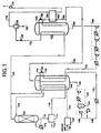
- Feed gas 90 typically a methane-containing gas and preferably natural gas, at a pressure up to 300 bar absolute (all pressures reported herein are absolute pressures) is dried and cleaned by known methods in pretreatment section 100 for the removal of acid gases such as CO 2 and H 2 S along with other contaminants such as mercury or mercury-containing compounds.
- Pretreated gas 102 enters the first heat exchanger or heat exchange zone 104 and is cooled therein to an intermediate temperature of -20°C to -70°C.
- the actual temperature level of this cooling step depends on the feed composition and desired LNG product specification (e.g. heating value), and sometimes is dictated by a desire to achieve a certain power split between compression services.
- Cooling in heat exchanger 104 is effected by the warming and vaporisation of high level mixed refrigerant stream 110, which typically contains one or more hydrocarbons selected from methane, ethane, propane, i-butane, butane, and possibly i-pentane, and may contain other components such as nitrogen.
- Cooled feed stream 108 is introduced into reboiled stripper or scrub column 106 for the removal of hydrocarbons heavier than methane.
- Bottoms product stream 112 enters fractionation section 114 in which pentane and heavier components are separated and recovered in stream 116.
- a portion of the bottoms stream from scrub column 106 is vaporised in heater 172 to provide boilup or stripping gas to the column.
- Butane and lighter components are recovered as stream 118, which is cooled in heat exchanger 104 and combined with the overhead product of scrub column 106 to yield precooled feed stream 120.
- fractionation may be carried out such that stream 118 contains propane and lighter components.
- Precooled feed stream 120 is further cooled and liquefied in heat exchanger 122 by indirect heat exchange by warming and vaporising low level mixed refrigerant stream 124.
- the resulting liquefied product stream 121 typically liquefied natural gas (LNG)
- LNG liquefied natural gas
- the pressure of liquefied product stream 121 may be reduced by work expansion across a turboexpander.
- the reduced pressure LNG product stream is introduced into storage tank 128, from which final liquefied product stream 130 is withdrawn.
- a significant quantity of light gas 132 can be evolved after the flashing across valve 126. Flash gas stream 132 typically is warmed, for example in heat exchanger 162, and compressed in offgas compressor 134 for use as fuel gas.
- Refrigeration to cool the natural gas feed from ambient temperature to a temperature of -20 °C to -70 °C is provided by a high level multi-component refrigeration loop as mentioned above.
- Stream 136 is the high level mixed refrigerant after compression and cooling, and typically contains some condensed liquid.
- the stream enters heat exchanger 104 at ambient temperature and an elevated pressure typically above 3 bar absolute, and is condensed, cooled, and optionally subcooled to a temperature of -20 °C to -70°C exiting as stream 138.
- Stream 138 is flashed adiabatically to a low pressure in the range of one to 30 bar absolute across throttling valve 150 and reduced pressure stream 110 is introduced to the cold end of heat exchanger 104.
- the pressure of cooled refrigerant stream 138 can be reduced by work expansion across a turboexpander.
- the flashing step which is defined as either isenthalpic or essentially isentropic pressure reduction, can include cooling or vaporisation and can be achieved either by throttling across a pressure reducing valve or by work expansion in a turboexpander or expansion engine.
- Flashed high level refrigerant stream 110 is warmed and vaporised in heat exchanger 104, and leaves the exchanger as vapour refrigerant stream 140, preferably at a temperature below the temperature of compressed refrigerant stream 136 returning to heat exchanger 104.
- Vapour refrigerant stream 140 is compressed in multi-staged intercooled compressor 142 to a pressure above 3 bar absolute.
- Liquid 144 can be formed in the intercooler(s) of staged compressor 142, and if so is preferably pumped and combined with compressed refrigerant vapour 146 from the final stage of compressor 142.
- Combined refrigerant stream 148 is cooled to near ambient temperature to provide high level mixed refrigerant stream 136 as earlier described. More than two stages of compression may be used as desired.
- Final cooling of gas feed stream 120 from -20 °C to -70 °C to the final liquefaction temperature is accomplished using a low level mixed refrigerant loop containing refrigerant components as earlier described.
- Compressed low level mixed refrigerant stream 152 at about ambient temperature and a pressure greater than 3 bar absolute enters exchanger 104 and is cooled therein by indirect heat exchange to a temperature of -20 °C to -70 °C, exiting as cooled low level mixed refrigerant stream 154.
- Refrigerant stream 154 is further cooled and optionally subcooled in heat exchanger 122 to a final temperature below -125°C, and the cooled stream 158 is flashed isenthalpically across throttling valve 156 to a pressure of about 3.3 bar absolute.
- the pressure of cooled stream 158 can be reduced by work expansion across a turboexpander or reciprocating expansion engine.
- a small portion of refrigerant stream 154, as stream 160, can be cooled in heat exchanger 162 by flash gas stream 132.
- Flashed low level mixed refrigerant stream 124 is introduced into the cold end of heat exchanger 122, where it vaporises to provide refrigeration therein.
- Vaporised low level mixed refrigerant stream 164 leaves heat exchanger 122 at a temperature below the temperature of cooled refrigerant stream 154 returning to heat exchanger 122.
- Vaporised refrigerant stream 164 then is compressed directly in multi-stage intercooled compressor 166 to greater than 5 bar absolute to provide low level mixed refrigerant stream 152.
- Vaporised low level mixed refrigerant stream 164 is not used to precool feed gas or other process streams, and therefore passes directly to compression without preheating.
- Heat exchangers 104 and 122 can utilise any suitable heat exchange devices such as wound coil, shell and tube, or plate-fin exchangers known in the art. Wound coil exchangers are preferred for their compact dimensions and efficient heat transfer performance.
- stream 118 containing butane and lighter components is recycled to exchanger 104, cooled therein, and divided into two portions 268 and 270.
- Portion 268 is used to as reflux in scrub column 106 for the removal of heavy components such as benzene to very low levels.
- Remaining portion 270 is combined with the overhead product of scrub column 106 to yield precooled feed stream 120.
- the relative flows of streams 268 and 270 will depend upon the feed composition and the required degree of contaminant removal from the feed stream.
- the system can be operated such that stream 118 contains predominantly propane and lighter components.
- FIG. 3 A second alternative embodiment of the present invention is shown in Fig. 3 wherein a small portion 374 of warm natural gas feed 102 is fed directly to scrub column 106 below the top location of feed stream 108 rather than being cooled in exchanger 104.
- This alternative reduces the amount of external heat required in reboiler exchanger 172 of scrub column 106 to generate stripping vapour.
- This alternative also decreases the refrigeration load in exchanger 104, and is beneficial when feed 102 contains high levels of heavier hydrocarbons and when the liquid fraction of stream 108 is high.
- FIG. 4 A third alternative embodiment of the present invention is shown in Figure 4.
- high level liquid refrigerant 144 condensing interstage in compressor 142 is fed directly to exchanger 404 rather than being pumped and combined with the compressor discharge as in Fig. 1.
- the compressed vapour refrigerant 146 is cooled and fed as stream 436 to exchanger 404, in which it is cooled and optionally subcooled to a temperature of -30 °C to -70 °C to provide stream 438, flashed across throttling valve 450, and fed to exchanger 404 as stream 410.
- Interstage refrigerant liquid stream 144 is fed to exchanger 404, cooled and optionally subcooled therein to a temperature warmer than stream 438, flashed across throttling valve 468, and introduced to exchanger 404 at an intermediate position in exchanger 404. Pressure drops across each of the throttling valves 450 and 468 are chosen such that the flashed fluids vaporise at essentially the same pressure.
- the term "essentially the same pressure" as used here means that the pressure of the vaporising refrigerant varies within an exchanger only by the small hydraulic or pneumatic pressure drops or variations caused by flowing liquid or vapour.
- the refrigerant is not vaporised in separate heat exchange conduits or zones at different pressures as described in many of the prior art processes earlier described.
- Fig. 4 can be operated at 3% - 4% higher efficiency than the embodiment of Fig. 1 but at higher capital cost. Also, heat exchanger 404 will be taller for a given surface area, potentially decreasing the attractiveness for shipboard applications.
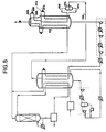
- FIG. 5 A fourth alternative embodiment of the invention is illustrated in Figure 5 wherein cooled low level mixed refrigerant stream 154 is a two-phase stream which is separated into vapour stream 568 and liquid stream 570 in drum 576. These refrigerant streams are introduced separately into heat exchanger 522. Vapour refrigerant stream 568 is liquefied and optionally subcooled to a low temperature to provide stream 558 and is flashed isenthalpically across throttling valve 556 to yield refrigerant stream 524, which is introduced into the cold end of heat exchanger 522 where it is vaporised to provide a portion of the refrigeration for product liquefaction.
- Liquid refrigerant stream 570 is subcooled in heat exchanger 522 to a temperature warmer than stream 558 and is flashed adiabatically across throttling valve 572 to low pressure refrigerant stream 574, which is introduced at an intermediate point into heat exchanger 522, where it is vaporised to provide the remaining portion of the refrigeration for product liquefaction.
- the vaporisation pressure of the two refrigerant streams in the heat exchanger is typically in the range of one to 30 bar absolute.
- Fig. 5 exhibits approximately 4% higher efficiency than the embodiment of Fig. 1, but will have a higher capital cost. Also, heat exchanger 522 will be taller for a given plot area, potentially decreasing the attractiveness for shipboard applications.
- Natural gas feed 90 is first cleaned and dried in pretreatment section 100 for the removal of acid gases such as CO 2 and H 2 S along with other contaminants such as mercury.
- Pretreated feed gas 102 at a flow rate of 17,470 kg-mole/h, a pressure of 52 bar absolute, and a temperature of 38 °C has a molar composition as given in Table 1 below.
- Pretreated feed gas 102 is precooled in heat exchanger 104 to a temperature of -36 °C and precooled feed stream 108 enters scrub column 106.
- the cooling in heat exchanger 104 is effected by the warming and vaporisation of high level mixed refrigerant stream 110 at a flow of 25,433 kg-mole/h.
- the composition of refrigerant stream 110 is as follows (in mole fractions): methane, 0.01; ethane, 0.47; propane, 0.06; i-butane, 0.16; and butane, 0.30.
- Pentane and heavier components of the feed are removed in scrub column 106. Bottoms product 112 of scrub column 106 enter fractionation section 114 in which components heavier than propane are recovered as stream 116. Propane and lighter components are recovered as stream 118 which is cooled to -36°C in heat exchanger 104 and recombined with the overhead product of the scrub column to form precooled feed stream 120 at a flow rate of 17,315 kg-mole/h.
- Precooled feed stream 120 is further cooled and liquefied in heat exchanger 122 to a temperature of -162 °C by indirect heat exchange with warming and vaporising low level mixed refrigerant stream 124, which enters heat exchanger 122 at a molar flow rate of 28,553 kg-mole/h, a temperature of -164 °C, a pressure of 3.35 bar absolute.
- the composition of refrigerant stream 120 is as follows (in mole fractions): nitrogen, 0.14; methane, 0.35; ethane, 0.41; and propane, 0.10.
- the resulting liquefied natural gas (LNG) stream (121) is then flashed adiabatically across throttling valve 126 to its bubble point pressure of 1.05 bar absolute.
- the flashed LNG stream enters tank 128 from which final LNG product stream 130 is withdrawn.
- no light gas 132 is evolved after flashing across valve 126, so that heat exchanger 162 and compressor 134 are not required.
- Refrigeration to cool the natural gas feed 102 from ambient temperature to a temperature of -36 °C is provided by a high level multi-component refrigeration loop as described earlier.
- High level mixed refrigerant stream 136 enters heat exchanger 104 at a temperature of 38 °C and a pressure of 24 bar absolute. It is cooled to a temperature of -36 °C in heat exchanger 104 then flashed across throttling valve 150 to yield reduced pressure refrigerant stream 110 at a temperature of -38 °C.
- Stream 110 is warmed and vaporised in heat exchanger 104, and exits therefrom at 34 °C and 3.8 bar absolute as refrigerant vapour stream 140.
- This low pressure refrigerant vapour is compressed in 2-stage intercooled compressor 142 to a final pressure of 24 bar absolute.
- Liquid 144 formed in the intercooler of the compressor is pumped and recombined with the compressed refrigerant 146 from the final compressor stage.
- the liquid flow of combined refrigerant stream 148 is 12,870 kg-mole/h.
- Final cooling of the natural gas feed from -36 °C to -162 °C in heat exchanger 122 is provided by a low level multi-component refrigeration loop as mentioned above.
- Compressed low level mixed refrigerant stream 152 enters heat exchanger 104 at a temperature of 38 °C and a pressure of 55 bar absolute, where it is cooled to a temperature of -36 °C as stream 154.
- This precooled low level refrigerant is further cooled to a temperature of -162 °C in heat exchanger 122 to yield stream 158, which is flashed across throttling valve 156.
- Reduced pressure refrigerant stream 124 is then warmed and vaporised in exchanger 122, finally exiting the exchanger 122 at -39 °C and 3.25 bar absolute as stream 164.
- This low pressure vapour refrigerant stream is then compressed in 3-stage intercooled compressor 166 to the final pressure of 55 bar absolute.
- the present invention provides for the liquefaction of feed gas using a minimum number of heat exchangers and utilises mixed refrigerants, wherein each refrigerant is vaporised at an essentially constant pressure in each of the exchangers.
- These characteristics reduce the process complexity and required plant plot plan area compared with known liquefaction processes.
- Each of the earlier described prior art processes utilises at least two refrigerant vaporisation pressure levels in at least one of the heat exchangers in low level and high level cooling service.
- the process and apparatus of the invention are especially well-suited for installation on ships and offshore platforms by virtue of simplified process features and minimum plot plan area requirements.
- the present invention includes the feature wherein feed precooling, low level refrigerant precooling, and high level refrigerant cooling are effected in a single heat exchanger against high level refrigerant vaporising at a single essentially constant pressure.
- the process does not require a separate feed precooling heat exchanger, since feed precooling is achieved in combination with low level refrigerant precooling and high level liquid refrigerant cooling.
- Low level mixed refrigerant is not used to precool the feed gas and therefore passes directly to compression without preheating. This results in a compressor which requires fewer intercoolers for a given overall pressure ratio, since the pressure ratio in the first stage can be quite high.
Abstract
Description
- The liquefaction of natural gas at remote sites, transportation of the liquefied natural gas (LNG) to population centres, and storage and vaporisation of LNG for local consumption have been successfully practised for many years around the world. LNG production sites are usually located on land at remote sites having docking facilities for large LNG tankers which transport the LNG to end users.
- Numerous process cycles have been developed for LNG production to provide the large refrigeration requirements for liquefaction. Such cycles typically utilise combinations of single-component refrigeration systems using propane or single chlorofluorocarbon refrigerants operated in combination with one or more mixed refrigerant (MR) systems. Well-known mixed refrigerants typically comprise light hydrocarbons and optionally nitrogen and utilise compositions tailored to the temperature and pressure levels of specific process steps.
- The objectives in the design and operation of current LNG process cycles and equipment have been to minimise energy consumption and maximise LNG production while operating at changing product demand rates and varying ambient temperature conditions. Since LNG production facilities are typically land-based in remote locations, the land area required for plant battery limits has not been a critical factor in plant design and layout.
- Numerous mixed refrigerant (MR) LNG cycles have been disclosed in the art. These cycles generally use a first refrigerant which vaporises at a higher temperature (i.e., the warm or high level MR) in a first heat exchanger (i.e., the warm or high level exchanger) and a second refrigerant which vaporises at a lower temperature (i.e., the cold or low level MR) in a second heat exchanger (i.e., the cold or low level exchanger). US-A-4,274,849 describes a dual mixed refrigerant process in which feed gas is first cooled in a separate exchanger using the refrigerant fluid exiting the cold or low level MR heat exchanger. The precooled feed is then further cooled and liquefied in the cold MR exchanger. The vaporised low level refrigerant after compression is cooled against the warm or high level refrigerant in the warm or high level MR exchanger. A disadvantage of this process is that an extra heat exchanger is required for feed precooling.
- US-A-4,112,700 discloses a dual MR process in which the high level MR is boiled at three different pressure levels with interstage compression. This requires the use of multiple heat exchangers or multiple heat exchange zones, which requires multiple return streams to the compressor. Such multiple heat exchange/compression stages have a disadvantage from a thermodynamic perspective, since non-equilibrium streams of differing compositions are mixed interstage in the warm mixed refrigerant compression train. The mixing of streams causes a thermodynamic irreversibility which will result in reduced cycle efficiency.
- A dual mixed refrigerant process is described in US-A-4,525,185 wherein the high level MR is boiled at three different pressure levels. This requires the use of multiple heat exchangers or heat exchange zones, and leads to multiple vessels, valves, and piping associated with the interstage feeds to the high level MR compressor, and increases the area required for the plant. In this process, the feed is first cooled using low level MR exiting the low level MR heat exchanger. The disadvantage of this approach is that an extra heat exchanger is required as in US-A-4,274,849 cited above. In this process cycle, non-equilibrium streams are mixed interstage in the high level mixed refrigerant compression train, which causes thermodynamic irreversibility and reduces cycle efficiency.
- US-A-4,545,795 discloses a dual MR process wherein the high level MR is boiled at three different pressure levels. This requires the use of multiple heat exchangers or heat exchange zones in the high level MR heat exchanger. In this process, the feed is first cooled using the fluid exiting the low level MR exchanger, and this requires an additional heat exchanger as in US-A-4,274,849 cited above. This flowsheet also has a disadvantage from a thermodynamic perspective, since non-equilibrium streams are mixed interstage in the high level MR compression train which causes thermodynamic irreversibility as earlier discussed.
- A dual mixed refrigerant process is described in US-A-4,539,028 in which the high level MR is boiled at three different pressure levels, which requires the use of multiple heat exchangers or heat exchange zones. The low level mixed MR is boiled at two different pressure levels, which also requires the use of multiple heat exchangers or heat exchange zones. In this process, the feed is first cooled using the low level MR, which requires an extra heat exchanger, a disadvantage shared by several of the processes cited above. This cycle also has a disadvantage from a thermodynamic perspective, since non-equilibrium streams are mixed interstage in the mixed refrigerant compression train. This mixing causes a thermodynamic irreversibility which will result in reduced cycle efficiency.
- A paper entitled "Liquefaction of Associated Gases" by H. Paradowski et al presented at the 7th International Conference on LNG, May 15-19, 1983 describes a dual MR process in which the high level mixed refrigerant is boiled at three different pressure levels. This requires the use of multiple heat exchangers or heat exchange zones. In addition, the feed is first cooled using the low level MR exiting the low level MR exchanger, and this requires an extra heat exchanger. This process also has a disadvantage from a thermodynamic perspective, since high level MR streams are generally not in thermal equilibrium with the interstage stream before the high level and interstage MR streams are mixed in the refrigerant compression train. This mixing of streams into the main flow of the compressor causes a thermodynamic irreversibility which will result in reduced cycle efficiency.
- US-A-4,911,741 discloses a dual MR process in which the high level MR is boiled at three different pressure levels. This requires the use of multiple heat exchangers or heat exchange zones and also has a disadvantage from a thermodynamic perspective as earlier discussed, since streams which are potentially at different temperatures are mixed interstage in the high level mixed refrigerant compression train. This mixing of streams causes thermodynamic irreversibility which will result in reduced cycle efficiency.
- A dual MR process is described in US-A-4,339,253 in which the high level MR is boiled at two different pressure levels. In addition, an interstage liquid stream from the high level MR is boiled at a third pressure. This requires the use of multiple heat exchangers or heat exchange zones. In this process, the feed is initially cooled before heavier hydrocarbon removal by heat exchange with the low level MR vapour exiting warm end of the low level MR exchanger. The disadvantage of this approach is that an extra heat exchanger is required. This heat exchange also increases the pressure drop of the low level MR stream before compression. As in several of the processes described above, this process has a thermodynamic disadvantage since non-equilibrium streams are mixed interstage in the high level MR compression train. The mixing of streams into the main flow causes thermodynamic irreversibility which will result in reduced cycle efficiency.
- US-A-4,094,655 describes a dual MR process where the low level MR is boiled at two different pressure levels, which requires the use of multiple heat exchangers or heat exchange zones. In this process, the high level MR is first cooled using the fluid from the low level MR exchangers, rather than being cooled by the high level mixed refrigerant loop itself. The disadvantage of this approach is that an extra heat exchanger is required. As in several of the processes described above, this process has a thermodynamic disadvantage since non-equilibrium streams are mixed interstage in the high level MR compression train. The mixing of streams into the main flow causes thermodynamic irreversibility which will result in reduced cycle efficiency.
- Additional dual MR processes in which the high level MR is boiled at several different pressure levels are described in US-A-4,504,296; US-A-4,525,185; US-A-4,755,200; and US-A-4,809,154.
- The LNG processes described above typically are utilised at land-based locations, and the land area required for the plant battery limits generally is not a critical factor in plant design and layout. Recently, commercial interest has been increasing in the potential recovery of gas reserves not amenable to land-based liquefaction processes as described above. Such reserves are found in offshore locations, and the recovery of these reserves has generated a growing need for gas liquefaction systems amenable to installation on ships (including barges) and offshore platforms.
- Most large LNG production plants employ a propane refrigerant cycle to precool the feed gas prior to further cooling and liquefaction by means of multicomponent or mixed refrigerant (MR) cycles. The propane pre-cooled cycle, while very efficient and cost effective in land-based plants, has certain disadvantages for shipboard (including barge mounted) applications. The necessity of maintaining fairly large quantities of propane presents potential safety concerns, and the numerous propane evaporators consume scarce plot plan area. Several examples of dual mixed refrigerant cycles as described above reduce propane inventory in propane precooling systems, but require numerous heat exchangers and vessels which increase the required plot plan area, and therefore are not suitable for offshore applications.
- The present invention addresses the need for a natural gas liquefaction process having a minimum plot plan area which is suitable for offshore applications and which can operate at high efficiency without propane precooling in a cycle which is both compact and cost effective. A natural gas liquefaction process and system to meet these objectives is described below and defined in the claims which follow.
- The present invention is an efficient process and apparatus for gas liquefaction which is particularly useful for the liquefaction of natural gas on a ship or offshore platform where space is at a premium. The invention minimises both the size and number of required equipment items.
- According to one aspect of the present invention, there is provided a process for liquefying a pressurised feed gas which comprises:
- (a) cooling the pressurised feed gas by indirect heat exchange in a first heat exchange zone with a first vaporising mixed refrigerant which is vaporised at a first essentially constant pressure to yield a cooled feed gas and a first mixed refrigerant vapour;
- (b) further cooling and condensing the cooled feed gas by indirect heat exchange in a second heat exchange zone with a second vaporising mixed refrigerant which is vaporised at a second essentially constant pressure to yield a liquid product and a second mixed refrigerant vapour;
- (c) compressing the first mixed refrigerant vapour; and cooling, condensing, and flashing the resulting compressed first mixed refrigerant vapour to provide the first vaporising mixed refrigerant; and
- (d) compressing the second mixed refrigerant vapour; and cooling, condensing, and flashing the resulting compressed second mixed refrigerant vapour to provide the second vaporising mixed refrigerant, wherein at least a portion of the refrigeration for the cooling and condensing of the second mixed refrigerant vapour is provided by indirect heat exchange in the first heat exchange zone with the first vaporising liquid mixed refrigerant.
-
- According to the invention, dual mixed component refrigerants are used to provide the refrigeration to the process, and no propane or other single hydrocarbon precooling systems are required. High level or warmer refrigeration can be provided in an optimum temperature range for removal of heavier hydrocarbons from the feed by distillation, and the refrigeration is provided at a single vaporising pressure for simultaneously precooling the natural gas feed and cooling the low level or cold mixed refrigerant.
- The low level mixed refrigerant provides refrigeration at a single vaporising pressure to achieve final cooling and liquefaction of the feed. The low level mixed refrigerant vapour preferably is compressed cold at approximately the minimum temperature provided by the high level mixed refrigerant.
- The high level refrigeration is provided using a mixed component circuit in which a high level mixed component stream is compressed and then cooled using an external cooling fluid such as air or cooling water. A portion of the mixed refrigerant may be liquefied by external cooling between compression stages. In an efficient embodiment of the invention this liquid is pumped, mixed with the gas exiting the final stage of compression, and cooled using external cooling. A portion of the compressed high level mixed refrigerant stream is liquefied after the external cooling.
- At least a portion of the compressed and cooled mixed refrigerant stream is further cooled and then reduced in pressure and vaporised by heat exchange while cooling the feed gas and low level mixed refrigerant. The evaporated and warmed mixed refrigerant steam is compressed and recirculated. The high level mixed refrigerant circuit suitably provides refrigeration at temperature levels from -20 °C to -70 °C as a fraction of the total refrigeration needed for natural gas liquefaction.
- The low level refrigeration is provided using a mixed component circuit in which a mixed component stream is compressed and cooled using an external cooling fluid such as air or cooling water. At least a portion of the compressed and cooled mixed refrigerant stream is further cooled in a heat exchanger using the high level mixed refrigerant, and after further cooling is reduced in pressure (flashed) and vaporised by heat exchange against the cooling and condensing feed gas stream. The evaporated and warmed mixed refrigerant steam is compressed cold without further heat exchange and recirculated.
- As indicated above, the compressing of the first mixed refrigerant vapour in (c) can be carried out as required in at least two stages of compression which generates at least one interstage two-phase refrigerant stream; the interstage two-phase refrigerant stream is separated into an interstage refrigerant vapour and an interstage refrigerant liquid; the interstage refrigerant vapour is compressed to yield a further compressed refrigerant; the interstage liquid refrigerant is pumped to yield a further pressurised liquid refrigerant; the further compressed refrigerant and the further pressurised liquid refrigerant is combined; and the resulting combined first mixed refrigerant is cooled, condensed, optionally subcooled, and flashed to provide the first vaporising mixed refrigerant in
- Alternatively, compressing of the first mixed refrigerant vapour in (c) above can be carried out if required in at least two stages of compression which generates an interstage compressed refrigerant; the interstage compressed refrigerant is cooled, partially condensed, and separated into an interstage refrigerant vapour and an interstage refrigerant liquid; the interstage refrigerant vapour is compressed to yield a further compressed refrigerant which is cooled, condensed, optionally subcooled, and flashed to provide the first vaporising mixed refrigerant in (a) above; and the interstage liquid refrigerant is subcooled and flashed at the first essentially constant pressure to yield additional refrigeration in the first heat exchange zone.
- At least a portion of the refrigeration for the cooling and condensing of the first mixed refrigerant vapour after compression can be provided by indirect heat exchange in the first heat exchange zone with the first vaporising liquid mixed refrigerant. Typically, the first vaporising mixed refrigerant is vaporised in a pressure range of one to 30 bar absolute (1 bar = 102kPa) and the second vaporising mixed refrigerant is vaporised in a pressure range of one to 15 bar absolute.
- The first mixed refrigerant vapour normally comprises two or more components selected from nitrogen, methane, ethane, ethylene, propane, propylene, i-butane, butane, i-pentane, chlorinated hydrocarbons, and fluorinated hydrocarbons. The second mixed refrigerant vapour normally comprises two or more components selected from nitrogen, methane, ethane, ethylene, propane, propylene, i-butane, butane, i-pentane, chlorinated hydrocarbons, and fluorinated hydrocarbons.
- Preferably the pressurised feed gas is provided by treating a pressurised stream of natural gas to remove contaminants selected from water, carbon dioxide, sulphur-containing compounds, mercury, and mercury-containing compounds. If required, hydrocarbons heavier than methane can be removed from the pressurised feed gas by
- (1) introducing the cooled feed gas into a distillation column at a first location, and withdrawing therefrom a methane-rich overhead stream and a bottoms stream of components heavier than methane; and
- (2) separating the bottoms stream to obtain a first hydrocarbon stream
comprising components with up to three or up to four carbon atoms and a second
hydrocarbon stream comprising components with more than three or four carbon atoms
respectively.
Usually, this process further comprises - (3) cooling at least a portion of the first hydrocarbon stream by indirect heat exchange in the first heat exchange zone; and
- (4) combining the resulting cooled hydrocarbon stream with the methane-rich overhead stream prior to the further cooling and condensing by indirect heat exchange in a second heat exchange zone in (b).
-
- The process of the invention may comprise removing hydrocarbons heavier than methane from the pressurised feed gas prior to further cooling and condensing by indirect heat exchange in the second heat exchange zone in (b) by
- (1) cooling the pressurised feed gas and introducing the resulting cooled feed gas into a distillation column at a first location and withdrawing therefrom a methane-rich overhead stream and a bottoms stream comprising components heavier than methane;
- (2) separating the bottoms stream to obtain a first hydrocarbon stream comprising components with up to three or up to four carbon atoms and a second hydrocarbon stream comprising components with greater than three or four carbon atoms respectively;
- (3) cooling at least a portion of the first hydrocarbon stream by indirect heat exchange in the first heat exchange zone; and
- (4) utilising at least a portion of the resulting cooled hydrocarbon stream of (3) as reflux for the distillation column of (1).
-
- Optionally, a portion of the pressurised feed gas can be introduced into the distillation column at a second location which is below the first location.
- The liquid product of (b) can be a methane-rich liquid, and the methane-rich liquid product can be flashed and separated to yield a further enriched liquid methane product and an offgas stream comprising components lighter than methane. A portion of the refrigeration for the cooling and condensing of the second mixed refrigerant vapour after compression can be provided at least in part by indirect heat exchange in a third heat exchange zone with the offgas stream comprising components lighter than methane.
- A portion of the refrigeration for the cooling and condensing of the second mixed refrigerant vapour after compression can be provided at least in part by indirect heat exchange in the second heat exchange zone with the second vaporising mixed refrigerant.
- The second mixed refrigerant vapour after compression can be cooled by indirect heat exchange in the first heat exchange zone and withdrawn therefrom at a first temperature; the resulting cooled second mixed refrigerant stream introduced into the second heat exchange zone and further cooled therein by indirect heat exchange; the second mixed refrigerant vapour withdrawn from the second heat exchange zone at a second temperature which is lower than the first temperature; and the resulting further cooled second mixed refrigerant vapour is compressed directly without preheating.
- Additionally or alternatively, the cooling and condensing of the second mixed refrigerant vapour following compression can be effected by indirect heat exchange in the first heat exchange zone to yield a partially condensed second mixed refrigerant stream containing intermediate second mixed refrigerant vapour and intermediate second mixed refrigerant liquid;
- (1) the partially condensed second mixed refrigerant stream separated to yield an intermediate second mixed refrigerant vapour and an intermediate second mixed refrigerant liquid;
- (2) the intermediate second mixed refrigerant vapour cooled, condensed, optionally subcooled, and flashed to provide the second vaporising mixed refrigerant of (c); and
- (3) the intermediate second mixed refrigerant liquid subcooled and flashed at the second essentially constant pressure to yield additional refrigeration in the second heat exchange zone.
-
- The invention includes an apparatus for liquefying a pressurised feed gas by the process of the invention, which apparatus comprises:
- (i) first heat exchange means for cooling pressurised feed gas and compressed second mixed refrigerant, wherein cooling is effected at least in part by indirect heat exchange with a first mixed refrigerant which is vaporised at a first essentially constant pressure;
- (ii) means for compressing, cooling and condensing the first mixed refrigerant vapour to provide condensed first mixed refrigerant;
- (iii) pressure reduction means for flashing the condensed first mixed refrigerant to provide the first vaporising mixed refrigerant;
- (iv) second heat exchange means for further cooling and condensing the cooled feed gas, wherein cooling is effected at least in part by indirect heat exchange with a second mixed refrigerant which is vaporised at a second essentially constant pressure;
- (v) means for compressing, cooling and condensing the second mixed refrigerant vapour to provide condensed second mixed refrigerant; and
- (vi) pressure reduction means for flashing the condensed second mixed refrigerant to provide the second vaporising mixed refrigerant.
-
- In a preferred embodiment, the apparatus comprises:
- (a) first heat exchange means for cooling pressurised feed gas, compressed first mixed refrigerant, and compressed second mixed refrigerant, wherein cooling is effected at least in part by indirect heat exchange with a first mixed refrigerant which is vaporised at a first essentially constant pressure;
- (b) first compression means for compressing the first mixed refrigerant vapour to provide the compressed first mixed refrigerant;
- (c) pressure reduction means for flashing the condensed first mixed refrigerant to provide the first vaporising mixed refrigerant;
- (d) second heat exchange means for further cooling and condensing the cooled feed gas and for further cooling and condensing the cooled second compressed mixed refrigerant, wherein cooling is effected at least in part by indirect heat exchange with a second mixed refrigerant which is vaporised at a second essentially constant pressure;
- (e) second compression means for compressing the second mixed refrigerant vapour to provide the compressed second mixed refrigerant; and
- (f) pressure reduction means for flashing the liquefied second mixed refrigerant to provide the second vaporising mixed refrigerant.
-
- The first compression means can comprise, if required,
- at least two compressor stages, one stage of which generates an interstage compressed refrigerant,
- an interstage cooler in which the interstage compressed refrigerant is cooled and partially condensed thereby yielding a two-phase interstage refrigerant,
- a separator in which the two-phase interstage refrigerant is separated into an interstage refrigerant vapour and an interstage refrigerant liquid; a further compressor stage in which the interstage refrigerant vapour is compressed to yield a further compressed refrigerant,
- pump means for pressurising the interstage refrigerant liquid, and
- piping means for combining the resulting pressurised interstage refrigerant liquid and the further compressed refrigerant to yield the compressed first mixed refrigerant of (a).
-
- Alternatively, the first compression means can comprise
- at least two compressor stages, one stage of which generates an interstage compressed refrigerant,
- an interstage cooler in which the interstage compressed refrigerant is cooled and partially condensed thereby yielding a two-phase interstage refrigerant,
- a separator in which the two-phase interstage refrigerant is separated into an interstage refrigerant vapour and an interstage refrigerant liquid, and
- a further compressor stage in which the interstage refrigerant vapour is compressed to yield a further compressed refrigerant, and wherein the apparatus further comprises
- piping means to provide the further compressed refrigerant as the compressed first mixed refrigerant for cooling, condensing, and flashing to provide the first vaporising mixed refrigerant,
- piping means to transfer the interstage refrigerant liquid to the first heat exchange means,
- heat transfer means within the first heat exchange means for cooling the interstage refrigerant liquid,
- pressure reduction means to flash the resulting cooled interstage refrigerant liquid to provide additional vaporising mixed refrigerant at the first essentially constant pressure, and
- piping means to introduce the additional vaporising mixed refrigerant into the first heat exchange means to provide refrigeration therein.
-
- The apparatus can also include
- (1) a separator for separating the cooled second compressed mixed refrigerant, when the cooled second compressed mixed refrigerant is partially condensed, to yield an intermediate second mixed refrigerant vapour and an intermediate second mixed refrigerant liquid;
- (2) heat transfer means within the second heat exchange means to cool the intermediate second mixed refrigerant liquid;
- (3) pressure reduction means to flash the resulting subcooled intermediate second mixed refrigerant liquid to provide additional vaporising mixed refrigerant at the second essentially constant pressure, and
- (4) piping means to introduce the additional vaporising mixed refrigerant into the second heat exchange means to provide refrigeration therein.
-
- The apparatus may further comprise
- (1) distillation for separating cooled pressurised methane-rich feed gas obtained from natural gas, into an overhead stream further enriched in methane and a bottoms stream comprising components heavier than methane;
- (2) separation means for separating the bottoms stream into a light hydrocarbon stream comprising components having up to three or up to four carbon atoms and a heavy hydrocarbon stream comprising components having more than three or four carbon atoms respectively;
- (3) cooling means within the first heat exchange means for cooling the light hydrocarbon stream; and
- (4) piping means for combining the resulting cooled light hydrocarbon stream of (3) with the overhead stream of (1) prior to the further cooling and condensing by indirect heat exchange in the second heat exchange means.
-
- Additionally or alternatively, the apparatus may comprise
- (1) distillation means for separating cooled pressurised methane-rich feed gas obtained from natural gas into an overhead stream of further enriched in methane and a bottoms stream of components heavier than methane;
- (2) separation means for separating the bottoms stream into a light hydrocarbon stream containing components having three or less or four or less carbon atoms and a heavy hydrocarbon stream comprising components having a more than three or more than four carbon atoms respectively;
- (3) cooling means within the first heat exchange means for cooling the light hydrocarbon stream; and
- (4) piping means for introducing a portion of the resulting cooled hydrocarbon stream of (3) as reflux for the distillation means.
-
- Optionally, the apparatus further comprises piping means for introducing a portion of the pressurised feed gas into the distillation means at a location which is below the location at which the cooled pressurised feed gas is introduced.
- The following is a description by way of example only and with reference to the accompanying drawings of presently preferred embodiments of the invention. In the drawings:-
- Fig. 1 is a schematic flowsheet of one preferred embodiment of the present invention;
- Fig. 2 is a schematic flowsheet of a first alternative embodiment of the present invention;
- Fig. 3 is a schematic flowsheet of a second alternative embodiment of the present invention;
- Fig. 4 is a schematic flowsheet of a third alternative embodiment of the present invention; and
- Fig. 5 is a schematic flowsheet of a fourth alternative embodiment of the present invention.
-
- The main embodiment of the invention is illustrated in Fig. 1.
Feed gas 90, typically a methane-containing gas and preferably natural gas, at a pressure up to 300 bar absolute (all pressures reported herein are absolute pressures) is dried and cleaned by known methods inpretreatment section 100 for the removal of acid gases such as CO2 and H2S along with other contaminants such as mercury or mercury-containing compounds. -
Pretreated gas 102 enters the first heat exchanger orheat exchange zone 104 and is cooled therein to an intermediate temperature of -20°C to -70°C. The actual temperature level of this cooling step depends on the feed composition and desired LNG product specification (e.g. heating value), and sometimes is dictated by a desire to achieve a certain power split between compression services. Cooling inheat exchanger 104 is effected by the warming and vaporisation of high level mixedrefrigerant stream 110, which typically contains one or more hydrocarbons selected from methane, ethane, propane, i-butane, butane, and possibly i-pentane, and may contain other components such as nitrogen. - Cooled
feed stream 108 is introduced into reboiled stripper orscrub column 106 for the removal of hydrocarbons heavier than methane.Bottoms product stream 112 entersfractionation section 114 in which pentane and heavier components are separated and recovered instream 116. A portion of the bottoms stream fromscrub column 106 is vaporised inheater 172 to provide boilup or stripping gas to the column. Butane and lighter components are recovered asstream 118, which is cooled inheat exchanger 104 and combined with the overhead product ofscrub column 106 to yieldprecooled feed stream 120. Alternatively, depending on LNG product specifications, fractionation may be carried out such thatstream 118 contains propane and lighter components. -
Precooled feed stream 120 is further cooled and liquefied inheat exchanger 122 by indirect heat exchange by warming and vaporising low level mixedrefrigerant stream 124. The resulting liquefiedproduct stream 121, typically liquefied natural gas (LNG), is flashed by adiabatic pressure reduction to a low pressure across throttlingvalve 126. Alternatively, the pressure of liquefiedproduct stream 121 may be reduced by work expansion across a turboexpander. - The reduced pressure LNG product stream is introduced into
storage tank 128, from which finalliquefied product stream 130 is withdrawn. In some cases, depending on the natural gas feed composition and the temperature ofstream 121 fromheat exchanger 122, a significant quantity oflight gas 132 can be evolved after the flashing acrossvalve 126.Flash gas stream 132 typically is warmed, for example inheat exchanger 162, and compressed inoffgas compressor 134 for use as fuel gas. - Refrigeration to cool the natural gas feed from ambient temperature to a temperature of -20 °C to -70 °C is provided by a high level multi-component refrigeration loop as mentioned above.
Stream 136 is the high level mixed refrigerant after compression and cooling, and typically contains some condensed liquid. The stream entersheat exchanger 104 at ambient temperature and an elevated pressure typically above 3 bar absolute, and is condensed, cooled, and optionally subcooled to a temperature of -20 °C to -70°C exiting as stream 138. Stream 138 is flashed adiabatically to a low pressure in the range of one to 30 bar absolute across throttling valve 150 and reducedpressure stream 110 is introduced to the cold end ofheat exchanger 104. Alternatively, the pressure of cooled refrigerant stream 138 can be reduced by work expansion across a turboexpander. The flashing step, which is defined as either isenthalpic or essentially isentropic pressure reduction, can include cooling or vaporisation and can be achieved either by throttling across a pressure reducing valve or by work expansion in a turboexpander or expansion engine. - Flashed high level
refrigerant stream 110 is warmed and vaporised inheat exchanger 104, and leaves the exchanger asvapour refrigerant stream 140, preferably at a temperature below the temperature of compressedrefrigerant stream 136 returning toheat exchanger 104. Vapourrefrigerant stream 140 is compressed in multi-stagedintercooled compressor 142 to a pressure above 3 bar absolute. Liquid 144 can be formed in the intercooler(s) of stagedcompressor 142, and if so is preferably pumped and combined with compressedrefrigerant vapour 146 from the final stage ofcompressor 142. Combinedrefrigerant stream 148 is cooled to near ambient temperature to provide high level mixedrefrigerant stream 136 as earlier described. More than two stages of compression may be used as desired. - The combined steps of condensing liquid between compression stages, pumping the condensed liquid to the pressure of the following compression stage vapour discharge, combining the vapour and liquid streams, and cooling the combined stream increases the efficiency of the overall gas liquefaction cycle. This is realised by a reduction in the mass flow of gas compressed by the following compression stage and a reduced refrigeration duty in
heat exchanger 104. - Final cooling of
gas feed stream 120 from -20 °C to -70 °C to the final liquefaction temperature is accomplished using a low level mixed refrigerant loop containing refrigerant components as earlier described. Compressed low level mixedrefrigerant stream 152 at about ambient temperature and a pressure greater than 3 bar absolute entersexchanger 104 and is cooled therein by indirect heat exchange to a temperature of -20 °C to -70 °C, exiting as cooled low level mixedrefrigerant stream 154. -
Refrigerant stream 154 is further cooled and optionally subcooled inheat exchanger 122 to a final temperature below -125°C, and the cooledstream 158 is flashed isenthalpically across throttlingvalve 156 to a pressure of about 3.3 bar absolute. Alternatively, the pressure of cooledstream 158 can be reduced by work expansion across a turboexpander or reciprocating expansion engine. A small portion ofrefrigerant stream 154, asstream 160, can be cooled inheat exchanger 162 byflash gas stream 132. - Flashed low level mixed
refrigerant stream 124 is introduced into the cold end ofheat exchanger 122, where it vaporises to provide refrigeration therein. Vaporised low level mixedrefrigerant stream 164 leavesheat exchanger 122 at a temperature below the temperature of cooledrefrigerant stream 154 returning toheat exchanger 122. Vaporisedrefrigerant stream 164 then is compressed directly in multi-stageintercooled compressor 166 to greater than 5 bar absolute to provide low level mixedrefrigerant stream 152. Vaporised low level mixedrefrigerant stream 164 is not used to precool feed gas or other process streams, and therefore passes directly to compression without preheating. -
Heat exchangers - An alternative embodiment of the present invention is shown in Figure 2. In this embodiment,
stream 118 containing butane and lighter components is recycled toexchanger 104, cooled therein, and divided into twoportions Portion 268 is used to as reflux inscrub column 106 for the removal of heavy components such as benzene to very low levels. Remainingportion 270 is combined with the overhead product ofscrub column 106 to yieldprecooled feed stream 120. The relative flows ofstreams stream 118 contains predominantly propane and lighter components. - A second alternative embodiment of the present invention is shown in Fig. 3 wherein a
small portion 374 of warmnatural gas feed 102 is fed directly to scrubcolumn 106 below the top location offeed stream 108 rather than being cooled inexchanger 104. This alternative reduces the amount of external heat required inreboiler exchanger 172 ofscrub column 106 to generate stripping vapour. This alternative also decreases the refrigeration load inexchanger 104, and is beneficial when feed 102 contains high levels of heavier hydrocarbons and when the liquid fraction ofstream 108 is high. - A third alternative embodiment of the present invention is shown in Figure 4. In this embodiment, high level
liquid refrigerant 144 condensing interstage incompressor 142 is fed directly toexchanger 404 rather than being pumped and combined with the compressor discharge as in Fig. 1. Thecompressed vapour refrigerant 146 is cooled and fed asstream 436 toexchanger 404, in which it is cooled and optionally subcooled to a temperature of -30 °C to -70 °C to providestream 438, flashed across throttlingvalve 450, and fed to exchanger 404 asstream 410. Interstage refrigerantliquid stream 144 is fed toexchanger 404, cooled and optionally subcooled therein to a temperature warmer thanstream 438, flashed across throttlingvalve 468, and introduced to exchanger 404 at an intermediate position inexchanger 404. Pressure drops across each of the throttlingvalves - The term "essentially the same pressure" as used here means that the pressure of the vaporising refrigerant varies within an exchanger only by the small hydraulic or pneumatic pressure drops or variations caused by flowing liquid or vapour. The refrigerant is not vaporised in separate heat exchange conduits or zones at different pressures as described in many of the prior art processes earlier described.
- The embodiment of Fig. 4 can be operated at 3% - 4% higher efficiency than the embodiment of Fig. 1 but at higher capital cost. Also,
heat exchanger 404 will be taller for a given surface area, potentially decreasing the attractiveness for shipboard applications. - A fourth alternative embodiment of the invention is illustrated in Figure 5 wherein cooled low level mixed
refrigerant stream 154 is a two-phase stream which is separated intovapour stream 568 andliquid stream 570 indrum 576. These refrigerant streams are introduced separately intoheat exchanger 522. Vapourrefrigerant stream 568 is liquefied and optionally subcooled to a low temperature to provide stream 558 and is flashed isenthalpically across throttling valve 556 to yieldrefrigerant stream 524, which is introduced into the cold end ofheat exchanger 522 where it is vaporised to provide a portion of the refrigeration for product liquefaction. Liquidrefrigerant stream 570 is subcooled inheat exchanger 522 to a temperature warmer than stream 558 and is flashed adiabatically across throttlingvalve 572 to low pressure refrigerant stream 574, which is introduced at an intermediate point intoheat exchanger 522, where it is vaporised to provide the remaining portion of the refrigeration for product liquefaction. The vaporisation pressure of the two refrigerant streams in the heat exchanger is typically in the range of one to 30 bar absolute. - The embodiment of Fig. 5 exhibits approximately 4% higher efficiency than the embodiment of Fig. 1, but will have a higher capital cost. Also,
heat exchanger 522 will be taller for a given plot area, potentially decreasing the attractiveness for shipboard applications. - A natural gas liquefaction process according to Fig. 1 was simulated in heat and material balance calculations to illustrate the present invention. Natural gas feed 90 is first cleaned and dried in
pretreatment section 100 for the removal of acid gases such as CO2 and H2S along with other contaminants such as mercury.Pretreated feed gas 102 at a flow rate of 17,470 kg-mole/h, a pressure of 52 bar absolute, and a temperature of 38 °C has a molar composition as given in Table 1 below.Feed Gas Composition for Fxample Component Mole Fraction Nitrogen 0.005 Methane 0.8738 Ethane 0.067 Propane 0.035 i-Butane 0.006 Butane 0.009 i-Pentane 0.003 Pentane 0.002 Hexane 0.001 -
Pretreated feed gas 102 is precooled inheat exchanger 104 to a temperature of -36 °C andprecooled feed stream 108 entersscrub column 106. The cooling inheat exchanger 104 is effected by the warming and vaporisation of high level mixedrefrigerant stream 110 at a flow of 25,433 kg-mole/h. The composition ofrefrigerant stream 110 is as follows (in mole fractions): methane, 0.01; ethane, 0.47; propane, 0.06; i-butane, 0.16; and butane, 0.30. - Pentane and heavier components of the feed are removed in
scrub column 106.Bottoms product 112 ofscrub column 106enter fractionation section 114 in which components heavier than propane are recovered asstream 116. Propane and lighter components are recovered asstream 118 which is cooled to -36°C inheat exchanger 104 and recombined with the overhead product of the scrub column to form precooledfeed stream 120 at a flow rate of 17,315 kg-mole/h. -
Precooled feed stream 120 is further cooled and liquefied inheat exchanger 122 to a temperature of -162 °C by indirect heat exchange with warming and vaporising low level mixedrefrigerant stream 124, which entersheat exchanger 122 at a molar flow rate of 28,553 kg-mole/h, a temperature of -164 °C, a pressure of 3.35 bar absolute. The composition ofrefrigerant stream 120 is as follows (in mole fractions): nitrogen, 0.14; methane, 0.35; ethane, 0.41; and propane, 0.10. - The resulting liquefied natural gas (LNG) stream (121) is then flashed adiabatically across throttling
valve 126 to its bubble point pressure of 1.05 bar absolute. The flashed LNG stream enterstank 128 from which finalLNG product stream 130 is withdrawn. In this Example, nolight gas 132 is evolved after flashing acrossvalve 126, so thatheat exchanger 162 andcompressor 134 are not required. - Refrigeration to cool the
natural gas feed 102 from ambient temperature to a temperature of -36 °C is provided by a high level multi-component refrigeration loop as described earlier. High level mixedrefrigerant stream 136 entersheat exchanger 104 at a temperature of 38 °C and a pressure of 24 bar absolute. It is cooled to a temperature of -36 °C inheat exchanger 104 then flashed across throttling valve 150 to yield reduced pressurerefrigerant stream 110 at a temperature of -38 °C. Stream 110 is warmed and vaporised inheat exchanger 104, and exits therefrom at 34 °C and 3.8 bar absolute asrefrigerant vapour stream 140. This low pressure refrigerant vapour is compressed in 2-stage intercooled compressor 142 to a final pressure of 24 bar absolute.Liquid 144 formed in the intercooler of the compressor is pumped and recombined with the compressed refrigerant 146 from the final compressor stage. The liquid flow of combinedrefrigerant stream 148 is 12,870 kg-mole/h. - Final cooling of the natural gas feed from -36 °C to -162 °C in
heat exchanger 122 is provided by a low level multi-component refrigeration loop as mentioned above. Compressed low level mixedrefrigerant stream 152 entersheat exchanger 104 at a temperature of 38 °C and a pressure of 55 bar absolute, where it is cooled to a temperature of -36 °C asstream 154. This precooled low level refrigerant is further cooled to a temperature of -162 °C inheat exchanger 122 to yieldstream 158, which is flashed across throttlingvalve 156. Reduced pressurerefrigerant stream 124 is then warmed and vaporised inexchanger 122, finally exiting theexchanger 122 at -39 °C and 3.25 bar absolute asstream 164. This low pressure vapour refrigerant stream is then compressed in 3-stage intercooled compressor 166 to the final pressure of 55 bar absolute. - Thus the present invention provides for the liquefaction of feed gas using a minimum number of heat exchangers and utilises mixed refrigerants, wherein each refrigerant is vaporised at an essentially constant pressure in each of the exchangers. These characteristics reduce the process complexity and required plant plot plan area compared with known liquefaction processes. Each of the earlier described prior art processes utilises at least two refrigerant vaporisation pressure levels in at least one of the heat exchangers in low level and high level cooling service. The process and apparatus of the invention are especially well-suited for installation on ships and offshore platforms by virtue of simplified process features and minimum plot plan area requirements.
- The present invention includes the feature wherein feed precooling, low level refrigerant precooling, and high level refrigerant cooling are effected in a single heat exchanger against high level refrigerant vaporising at a single essentially constant pressure. In addition, the process does not require a separate feed precooling heat exchanger, since feed precooling is achieved in combination with low level refrigerant precooling and high level liquid refrigerant cooling. Low level mixed refrigerant is not used to precool the feed gas and therefore passes directly to compression without preheating. This results in a compressor which requires fewer intercoolers for a given overall pressure ratio, since the pressure ratio in the first stage can be quite high.
- The essential characteristics of the present invention are described completely in the foregoing disclosure. One skilled in the art can understand the invention and make various modifications without departing from the scope of the claims which follow.
Claims (20)
- A process for liquefying a pressurised feed gas which comprises:(a) cooling the pressurised feed gas by indirect heat exchange in a first heat exchange zone with a first vaporising mixed refrigerant which is vaporised at a first essentially constant pressure to yield a cooled feed gas and a first mixed refrigerant vapour;(b) further cooling and condensing the cooled feed gas by indirect heat exchange in a second heat exchange zone with a second vaporising mixed refrigerant which is vaporised at a second essentially constant pressure to yield a liquid product and a second mixed refrigerant vapour;(c) compressing, cooling and condensing the first mixed refrigerant vapour; and flashing the resulting condensed first mixed refrigerant to provide the first vaporising mixed refrigerant; and(d) compressing, cooling and condensing the second mixed refrigerant vapour; and flashing the resulting condensed second mixed refrigerant to provide the second vaporising mixed refrigerant, wherein at least a portion of the refrigeration for the cooling and condensing of the second mixed refrigerant vapour is provided by indirect heat exchange in the first heat exchange zone with the first vaporising liquid mixed refrigerant.
- A process as claimed in Claim 1, wherein the compressing of the first mixed refrigerant vapour in (c) is carried out in at least two stages of compression which generates at least one interstage two-phase refrigerant stream; the interstage two-phase refrigerant stream is separated into an interstage refrigerant vapour and an interstage refrigerant liquid; the interstage refrigerant vapour is compressed to yield a further compressed refrigerant; the interstage liquid refrigerant is pumped to yield a further pressurised liquid refrigerant; the further compressed refrigerant and the further pressurised liquid refrigerant are combined; and the resulting combined first mixed refrigerant is cooled, condensed, optionally subcooled, and flashed to provide the first vaporising mixed refrigerant in (a).
- A process as claimed in Claim 1, wherein the compressing of the first mixed refrigerant vapour in (c) is carried out in at least two stages of compression which generates an interstage compressed refrigerant; the interstage compressed refrigerant is cooled, partially condensed, and separated into an interstage refrigerant vapour and an interstage refrigerant liquid; the interstage refrigerant vapour is compressed to yield a further compressed refrigerant which is cooled, condensed, optionally subcooled, and flashed to provide the first vaporising mixed refrigerant in (a); and the interstage liquid refrigerant is subcooled and flashed at the first essentially constant pressure to yield additional refrigeration in the first heat exchange zone.
- A process as claimed in any one of the preceding claims, wherein at least a portion of the refrigeration for the cooling and condensing of the first mixed refrigerant vapour after compression is provided by indirect heat exchange in the first heat exchange zone with the first vaporising liquid mixed refrigerant.
- A process as claimed in any one of the preceding claims, wherein the pressurised feed gas is provided by treating a pressurised stream of natural gas to remove contaminants selected from water, carbon dioxide, sulphur-containing compounds, mercury, and mercury-containing compounds.
- A process as claimed in Claim 5, which further comprises(1) introducing the cooled feed gas into a distillation column at a first location, and withdrawing therefrom a methane-rich overhead stream and a bottoms stream of components heavier than methane;(2) separating the bottoms stream to obtain a first hydrocarbon stream comprising components with up to three or up to four carbon atoms and a second hydrocarbon stream comprising components with more than three or more than four carbon atoms respectively;(3) cooling at least a portion of the first hydrocarbon stream by indirect heat exchange in the first heat exchange zone; and(4) combining at least part of the resulting cooled hydrocarbon stream with the methane-rich overhead stream prior to the further cooling and condensing by indirect heat exchange in the second heat exchange zone in (b).
- A process as claimed in Claim 5 or Claim 6, which further comprises(1) introducing the cooled feed gas into a distillation column at a first location and withdrawing therefrom a methane-rich overhead stream and a bottoms stream comprising components heavier than methane;(2) separating the bottoms stream to obtain a first hydrocarbon stream comprising components with up to three or up to four carbon atoms and a second hydrocarbon stream comprising components with more than three or more than four carbon atoms respectively;(3) cooling at least a portion the first hydrocarbon stream by indirect heat exchange in the first heat exchange zone; and(4) utilising at least a portion of the resulting cooled hydrocarbon stream of (3) as reflux for the distillation column of (1).
- A process as claimed in Claim 6 or Claim 7, which further comprises introducing a portion of the pressurised feed gas into the distillation column at a second location which is below said first location.
- A process as claimed in any one of Claims 5 to 8, wherein the liquid product of (b) is flashed to provide a further methane-enriched liquid product and an offgas stream comprising components lighter than methane and wherein a portion of the refrigeration for the cooling and condensing of the second mixed refrigerant vapour after compression is provided in part by indirect heat exchange in a third heat exchange zone with said offgas stream.
- A process as claimed in any one of the preceding claims, wherein a portion of the refrigeration for the cooling and condensing of the second mixed refrigerant vapour after compression is provided at least in part by indirect heat exchange in the second heat exchange zone with the second vaporising mixed refrigerant.
- A process as claimed in any one of the preceding claims, whereinthe second mixed refrigerant vapour after compression is cooled by indirect heat exchange in the first heat exchange zone and is withdrawn therefrom at a first temperature,the resulting cooled second mixed refrigerant stream is introduced into the second heat exchange zone and is further cooled therein by indirect heat exchange,the second mixed refrigerant vapour is withdrawn from the second heat exchange zone at a second temperature which is lower than the first temperature, andthe resulting further cooled second mixed refrigerant vapour is compressed directly without preheating.
- A process as claimed in any one of the preceding claims, wherein the cooling and condensing of the second mixed refrigerant vapour following compression is effected by indirect heat exchange in the first heat exchange zone to yield a partially condensed second mixed refrigerant stream containing intermediate second mixed refrigerant vapour and intermediate second mixed refrigerant liquid, and further wherein(1) the partially condensed second mixed refrigerant stream is separated to yield an intermediate second mixed refrigerant vapour and an intermediate second mixed refrigerant liquid;(2) the intermediate second mixed refrigerant vapour is cooled, condensed, optionally subcooled, and flashed to provide the second vaporising mixed refrigerant of (c); and(3) the intermediate second mixed refrigerant liquid is subcooled and flashed at the second essentially constant pressure to yield additional refrigeration in the second heat exchange zone.
- An apparatus for liquefying a pressurised feed gas by a process as defined in Claim 1, which apparatus comprises:(i) first heat exchange means (104) for cooling pressurised feed gas (102) and compressed second mixed refrigerant (152), wherein cooling is effected at least in part by indirect heat exchange with a first mixed refrigerant (110) which is vaporised at a first essentially constant pressure;(ii) means (142, 140) for compressing, cooling and condensing the first mixed refrigerant vapour (140) to provide condensed first mixed refrigerant (138);(iii) pressure reduction means (150) for flashing the condensed first mixed refrigerant (138) to provide the first vaporising mixed refrigerant (110);(iv) second heat exchange means (122) for further cooling and condensing the cooled feed gas (120), wherein cooling is effected at least in part by indirect heat exchange with a second mixed refrigerant (124) which is vaporised at a second essentially constant pressure;(v) means (166, 104) for compressing, cooling and condensing the second mixed refrigerant vapour (164) to provide condensed second mixed refrigerant (158); and(vi) pressure reduction means (156) for flashing the condensed second mixed refrigerant (158) to provide the second vaporising mixed refrigerant (124).
- A apparatus as claimed in Claim 13, which comprises:(a) first heat exchange means (104) for cooling pressurised feed gas (102), compressed first mixed refrigerant (148), and compressed second mixed refrigerant (152), wherein cooling is effected at least in part by indirect heat exchange with a first mixed refrigerant (110) which is vaporised at a first essentially constant pressure;(b) first compression means (142) for compressing the first mixed refrigerant vapour (140) to provide the compressed first mixed refrigerant (148);(c) pressure reduction means (150) for flashing the condensed first mixed refrigerant to provide the first vaporising mixed refrigerant (110);(d) second heat exchange means (122) for further cooling and condensing the cooled feed gas (120) and for further cooling and condensing the cooled second compressed mixed refrigerant (154), wherein cooling is effected at least in part by indirect heat exchange with a second mixed refrigerant (124) which is vaporised at a second essentially constant pressure;(e) second compression means (166) for compressing the second mixed refrigerant vapour (164) to provide the compressed second mixed refrigerant (152); and(f) pressure reduction means (156) for flashing the condensed second mixed refrigerant (158) to provide the second vaporising mixed refrigerant (124).
- An apparatus as claimed in Claim 14, wherein the first compression means (142) comprisesat least two compressor stages, one stage of which generates an interstage compressed refrigerant,an interstage cooler in which the interstage compressed refrigerant is cooled and partially condensed thereby yielding a two-phase interstage refrigerant,a separator in which the two-phase interstage refrigerant is separated into an interstage refrigerant vapour and an interstage refrigerant liquid (144);a further compressor stage in which the interstage refrigerant vapour is compressed to yield a further compressed refrigerant (146),pump means for pressurising the interstage refrigerant liquid (144), andpiping means for combining the resulting pressurised interstage refrigerant liquid and the further compressed refrigerant to yield the compressed first mixed refrigerant.
- An apparatus as claimed in Claim 14, wherein the first compression means (142) comprisesat least two compressor stages, one stage of which generates an interstage compressed refrigerant,an interstage cooler in which the interstage compressed refrigerant is cooled and partially condensed thereby yielding a two-phase interstage refrigerant,a separator in which the two-phase interstage refrigerant is separated into an interstage refrigerant vapour and an interstage refrigerant liquid, anda further compressor stage in which the interstage refrigerant vapour is compressed to yield a further compressed refrigerant, and wherein the apparatus further comprisespiping means to provide the further compressed refrigerant as the compressed first mixed refrigerant for cooling, condensing, and flashing to provide the first vaporising mixed refrigerant in (a),piping means transfer the interstage refrigerant liquid to the first heat exchange means (104),heat transfer means within the first heat exchange means (104) for cooling the interstage refrigerant liquid,pressure reduction means to flash the resulting cooled interstage refrigerant liquid to provide additional vaporising mixed refrigerant at the first essentially constant pressure, andpiping means to introduce the additional vaporising mixed refrigerant into the first heat exchange means (104) to provide refrigeration therein.
- An apparatus as claimed in any one of Claims 13 to 16, which further comprises(1) distillation means (106) for separating cooled pressurised methane-rich feed gas (108) obtained from natural gas into an overhead stream further enriched in methane and a bottoms stream (112) comprising components heavier than methane;(2) separation means (114) for separating the bottoms stream (112) into a light hydrocarbon stream (118) comprising components having three or less or four or less carbon atoms and a heavy hydrocarbon stream (116) comprising components having more than three or more than four carbon atoms respectively;(3) cooling means within the first heat exchange means (104) for cooling the light hydrocarbon stream (118); and(4) piping means for combining the resulting cooled light hydrocarbon stream of (3) with the overhead stream of (1) prior to the further cooling and condensing by indirect heat exchange in the second heat exchange means (122).
- An apparatus as claimed in any one of Claims 13 to 16, which comprises(1) distillation means (106) for separating cooled pressurised methane-rich feed gas (108) obtained from natural gas into an overhead stream of further enriched in methane and a bottoms stream (112) of components heavier than methane;(2) separation means (114) for separating the bottoms stream (112) into a light hydrocarbon stream (118) containing components having three or less or four or less carbon atoms and a heavy hydrocarbon stream (116) comprising components having more than three or more than four carbon atoms respectively;(3) cooling means within the first heat exchange means (104) for cooling the light hydrocarbon stream (118); and(4) piping means (268) for introducing a portion of the resulting cooled hydrocarbon stream of (3) as reflux for the distillation means (106).
- An apparatus as claimed in Claim 17 or Claim 18, which further comprises piping means for introducing a portion (374) of the pressurised feed gas (102) into the distillation means (106) at a location which is below the location at which the cooled pressurised feed gas (108) is introduced.
- An apparatus as claimed in any one of Claims 13 to 19, which further comprises(1) a separator (576) for separating the cooled second compressed mixed refrigerant (154), when the cooled second compressed mixed refrigerant (154) is partially condensed, to yield an intermediate second mixed refrigerant vapour (568) and an intermediate second mixed refrigerant liquid (570);(2) heat transfer means within the second heat exchange means (522) to cool the intermediate second mixed refrigerant liquid (570);(3) pressure reduction means (572) to flash the resulting subcooled intermediate second mixed refrigerant liquid to provide additional vaporising mixed refrigerant at the second essentially constant pressure, and(4) piping means (574) to introduce the additional vaporising mixed refrigerant into the second heat exchange means (522) to provide refrigeration therein.
Priority Applications (1)
| Application Number | Priority Date | Filing Date | Title |
|---|---|---|---|
| EP03007634A EP1323994B1 (en) | 1998-12-09 | 1999-12-07 | Dual mixed refrigerant cycle for gas liquefaction |
Applications Claiming Priority (2)
| Application Number | Priority Date | Filing Date | Title |
|---|---|---|---|
| US208562 | 1998-12-09 | ||
| US09/208,562 US6119479A (en) | 1998-12-09 | 1998-12-09 | Dual mixed refrigerant cycle for gas liquefaction |
Related Child Applications (1)
| Application Number | Title | Priority Date | Filing Date |
|---|---|---|---|
| EP03007634A Division EP1323994B1 (en) | 1998-12-09 | 1999-12-07 | Dual mixed refrigerant cycle for gas liquefaction |
Publications (3)
| Publication Number | Publication Date |
|---|---|
| EP1008823A2 true EP1008823A2 (en) | 2000-06-14 |
| EP1008823A3 EP1008823A3 (en) | 2000-11-15 |
| EP1008823B1 EP1008823B1 (en) | 2004-09-15 |
Family
ID=22775052
Family Applications (2)
| Application Number | Title | Priority Date | Filing Date |
|---|---|---|---|
| EP03007634A Expired - Lifetime EP1323994B1 (en) | 1998-12-09 | 1999-12-07 | Dual mixed refrigerant cycle for gas liquefaction |
| EP99309813A Expired - Lifetime EP1008823B1 (en) | 1998-12-09 | 1999-12-07 | Dual mixed refrigerant cycle for gas liquefaction |
Family Applications Before (1)
| Application Number | Title | Priority Date | Filing Date |
|---|---|---|---|
| EP03007634A Expired - Lifetime EP1323994B1 (en) | 1998-12-09 | 1999-12-07 | Dual mixed refrigerant cycle for gas liquefaction |
Country Status (15)
| Country | Link |
|---|---|
| US (2) | US6119479A (en) |
| EP (2) | EP1323994B1 (en) |
| JP (1) | JP3466977B2 (en) |
| KR (1) | KR100350934B1 (en) |
| CN (1) | CN1256392A (en) |
| AT (2) | ATE276498T1 (en) |
| AU (1) | AU736518B2 (en) |
| BR (1) | BR9905789A (en) |
| CA (1) | CA2291415C (en) |
| DE (2) | DE69920147T2 (en) |
| ES (1) | ES2246028T3 (en) |
| ID (1) | ID24002A (en) |
| MY (1) | MY117202A (en) |
| NO (1) | NO315534B1 (en) |
| TW (1) | TW421703B (en) |
Cited By (6)
| Publication number | Priority date | Publication date | Assignee | Title |
|---|---|---|---|---|
| FR2957407A1 (en) * | 2010-03-15 | 2011-09-16 | Inst Francais Du Petrole | METHOD FOR LIQUEFACTING A NATURAL GAS WITH REFRIGERANT MIXTURES CONTAINING AT LEAST ONE UNSATURATED HYDROCARBON |
| US8578734B2 (en) | 2006-05-15 | 2013-11-12 | Shell Oil Company | Method and apparatus for liquefying a hydrocarbon stream |
| EP2251625A3 (en) * | 2009-05-05 | 2014-11-26 | Air Products And Chemicals, Inc. | Pre-cooled liquefaction process of natural gas |
| US10539363B2 (en) | 2008-02-14 | 2020-01-21 | Shell Oil Company | Method and apparatus for cooling a hydrocarbon stream |
| US10852060B2 (en) | 2011-04-08 | 2020-12-01 | Pilot Energy Solutions, Llc | Single-unit gas separation process having expanded, post-separation vent stream |
| CZ308591B6 (en) * | 2019-10-04 | 2020-12-16 | Siad Macchine Impianti S.P.A. | Natural gas processing equipment |
Families Citing this family (85)
| Publication number | Priority date | Publication date | Assignee | Title |
|---|---|---|---|---|
| US6119479A (en) * | 1998-12-09 | 2000-09-19 | Air Products And Chemicals, Inc. | Dual mixed refrigerant cycle for gas liquefaction |
| US6742358B2 (en) * | 2001-06-08 | 2004-06-01 | Elkcorp | Natural gas liquefaction |
| FR2829569B1 (en) * | 2001-09-13 | 2006-06-23 | Technip Cie | METHOD FOR LIQUEFACTING NATURAL GAS, USING TWO REFRIGERATION CYCLES |
| US6427483B1 (en) | 2001-11-09 | 2002-08-06 | Praxair Technology, Inc. | Cryogenic industrial gas refrigeration system |
| EP1367350B2 (en) | 2002-05-27 | 2012-10-24 | Air Products And Chemicals, Inc. | Coil wound heat exchanger |
| US6666046B1 (en) * | 2002-09-30 | 2003-12-23 | Praxair Technology, Inc. | Dual section refrigeration system |
| US6945075B2 (en) * | 2002-10-23 | 2005-09-20 | Elkcorp | Natural gas liquefaction |
| MXPA05008280A (en) * | 2003-02-25 | 2006-03-21 | Ortloff Engineers Ltd | Hydrocarbon gas processing. |
| US6889523B2 (en) | 2003-03-07 | 2005-05-10 | Elkcorp | LNG production in cryogenic natural gas processing plants |
| US6742357B1 (en) | 2003-03-18 | 2004-06-01 | Air Products And Chemicals, Inc. | Integrated multiple-loop refrigeration process for gas liquefaction |
| MXPA05009889A (en) | 2003-03-18 | 2005-12-05 | Air Prod & Chem | Integrated multiple-loop refrigeration process for gas liquefaction. |
| US6662589B1 (en) | 2003-04-16 | 2003-12-16 | Air Products And Chemicals, Inc. | Integrated high pressure NGL recovery in the production of liquefied natural gas |
| US7155931B2 (en) * | 2003-09-30 | 2007-01-02 | Ortloff Engineers, Ltd. | Liquefied natural gas processing |
| JP4912564B2 (en) * | 2003-11-18 | 2012-04-11 | 日揮株式会社 | Gas liquefaction plant |
| DE102004011483A1 (en) * | 2004-03-09 | 2005-09-29 | Linde Ag | Process for liquefying a hydrocarbon-rich stream |
| US7204100B2 (en) * | 2004-05-04 | 2007-04-17 | Ortloff Engineers, Ltd. | Natural gas liquefaction |
| US7866184B2 (en) * | 2004-06-16 | 2011-01-11 | Conocophillips Company | Semi-closed loop LNG process |
| ES2284429T1 (en) * | 2004-07-01 | 2007-11-16 | Ortloff Engineers, Ltd | LICUATED NATURAL GAS PROCESSING. |
| JP2008509374A (en) * | 2004-08-06 | 2008-03-27 | ビーピー・コーポレーション・ノース・アメリカ・インコーポレーテッド | Natural gas liquefaction method |
| PE20060989A1 (en) * | 2004-12-08 | 2006-11-06 | Shell Int Research | METHOD AND DEVICE FOR PRODUCING A LIQUID NATURAL GAS CURRENT |
| US20070107464A1 (en) * | 2005-11-14 | 2007-05-17 | Ransbarger Weldon L | LNG system with high pressure pre-cooling cycle |
| US20070204649A1 (en) * | 2006-03-06 | 2007-09-06 | Sander Kaart | Refrigerant circuit |
| KR101407771B1 (en) * | 2006-06-02 | 2014-06-16 | 오르트로프 엔지니어스, 리미티드 | Liquefied natural gas processing |
| EP2044376A2 (en) * | 2006-07-21 | 2009-04-08 | Shell Internationale Research Maatschappij B.V. | Method and apparatus for liquefying a hydrocarbon stream |
| RU2443952C2 (en) * | 2006-09-22 | 2012-02-27 | Шелл Интернэшнл Рисерч Маатсхаппий Б.В. | Method and device for liquefaction of hydrocarbons flow |
| US20080078205A1 (en) * | 2006-09-28 | 2008-04-03 | Ortloff Engineers, Ltd. | Hydrocarbon Gas Processing |
| US8250883B2 (en) * | 2006-12-26 | 2012-08-28 | Repsol Ypf, S.A. | Process to obtain liquefied natural gas |
| US8590340B2 (en) * | 2007-02-09 | 2013-11-26 | Ortoff Engineers, Ltd. | Hydrocarbon gas processing |
| RU2458296C2 (en) * | 2007-05-03 | 2012-08-10 | Эксонмобил Апстрим Рисерч Компани | Natural gas liquefaction method |
| US9869510B2 (en) * | 2007-05-17 | 2018-01-16 | Ortloff Engineers, Ltd. | Liquefied natural gas processing |
| BRPI0813637B1 (en) * | 2007-07-09 | 2019-07-09 | Lng Technology Pty Ltd | PROCESS AND SYSTEM FOR PRODUCTION OF LIQUID NATURAL GAS |
| US8919148B2 (en) * | 2007-10-18 | 2014-12-30 | Ortloff Engineers, Ltd. | Hydrocarbon gas processing |
| US8511103B2 (en) * | 2007-12-28 | 2013-08-20 | Johnson Controls Technology Company | Vapor compression system |
| US20090282865A1 (en) | 2008-05-16 | 2009-11-19 | Ortloff Engineers, Ltd. | Liquefied Natural Gas and Hydrocarbon Gas Processing |
| DE102009018248A1 (en) * | 2009-04-21 | 2010-10-28 | Linde Aktiengesellschaft | Process for liquefying a hydrocarbon-rich fraction |
| US20100287982A1 (en) * | 2009-05-15 | 2010-11-18 | Ortloff Engineers, Ltd. | Liquefied Natural Gas and Hydrocarbon Gas Processing |
| US8434325B2 (en) | 2009-05-15 | 2013-05-07 | Ortloff Engineers, Ltd. | Liquefied natural gas and hydrocarbon gas processing |
| NO333898B1 (en) * | 2009-12-22 | 2013-10-14 | Waertsilae Oil & Gas Systems As | Hot cargo loading method and system |
| CN102115683A (en) * | 2009-12-30 | 2011-07-06 | 中国科学院理化技术研究所 | Method for producing liquefied natural gas |
| KR101266675B1 (en) * | 2009-12-31 | 2013-05-28 | 엘지전자 주식회사 | Water circulation system associated with refrigerant cycle |
| US9021832B2 (en) * | 2010-01-14 | 2015-05-05 | Ortloff Engineers, Ltd. | Hydrocarbon gas processing |
| US9441877B2 (en) | 2010-03-17 | 2016-09-13 | Chart Inc. | Integrated pre-cooled mixed refrigerant system and method |
| KR101009892B1 (en) * | 2010-04-30 | 2011-01-20 | 한국가스공사연구개발원 | Natural gas liquefaction process |
| CN102933273B (en) | 2010-06-03 | 2015-05-13 | 奥特洛夫工程有限公司 | Hydrocarbon gas processing |
| CA2803468C (en) * | 2010-06-30 | 2018-07-24 | Shell Internationale Research Maatschappij B.V. | Method of treating a hydrocarbon stream comprising methane, and an apparatus therefor |
| KR101628841B1 (en) * | 2010-07-08 | 2016-06-10 | 대우조선해양 주식회사 | Method and apparatus for liquefying natural gas |
| DE102011015433A1 (en) * | 2011-03-29 | 2012-10-04 | Linde Ag | heat exchanger system |
| CN102954668A (en) * | 2011-08-19 | 2013-03-06 | 李志远 | Method for producing liquefied natural gas by multi-component refrigerant double-stage compression |
| AP2014007704A0 (en) * | 2011-12-20 | 2014-06-30 | Conocophillips Co | Internal baffle for suppressing slosh in a core-in-shell heat exchanger |
| CN102564059A (en) * | 2012-02-19 | 2012-07-11 | 中国石油集团工程设计有限责任公司 | Twin-stage multi-component mixed refrigerant refrigeration natural gas liquefaction system and method |
| US20130269386A1 (en) | 2012-04-11 | 2013-10-17 | Air Products And Chemicals, Inc. | Natural Gas Liquefaction With Feed Water Removal |
| CN102706024B (en) * | 2012-06-04 | 2015-06-17 | 上海森鑫新能源科技有限公司 | Stepped refrigerating system and method for recovering oil gas and defrosting method |
| FR2993350B1 (en) * | 2012-07-13 | 2018-06-15 | Air Liquide | METHOD AND APPARATUS FOR COOLING A FLOW CONTAINING AT LEAST 35% CARBON DIOXIDE AND MERCURY |
| FR2993643B1 (en) * | 2012-07-17 | 2014-08-22 | Saipem Sa | NATURAL GAS LIQUEFACTION PROCESS WITH PHASE CHANGE |
| AU2013356460B2 (en) * | 2012-12-04 | 2018-04-05 | Conocophillips Company | Use of low global-warming potential, low ozone depletion potential, low combustibility hydrofluoro-olefin, xenon or iodo compound refrigerants in LNG processing |
| US20140157822A1 (en) * | 2012-12-06 | 2014-06-12 | L'air Liquide Societe Anonyme Pour L'etude Et L'exploitation Des Procedes Georges Claude | Thermal performing refrigeration cycle |
| US11408673B2 (en) | 2013-03-15 | 2022-08-09 | Chart Energy & Chemicals, Inc. | Mixed refrigerant system and method |
| US11428463B2 (en) | 2013-03-15 | 2022-08-30 | Chart Energy & Chemicals, Inc. | Mixed refrigerant system and method |
| CA2907444C (en) | 2013-03-15 | 2022-01-18 | Douglas A. Ducote, Jr. | Mixed refrigerant system and method |
| US10436505B2 (en) | 2014-02-17 | 2019-10-08 | Black & Veatch Holding Company | LNG recovery from syngas using a mixed refrigerant |
| US10443930B2 (en) | 2014-06-30 | 2019-10-15 | Black & Veatch Holding Company | Process and system for removing nitrogen from LNG |
| CN104457137B (en) * | 2014-11-19 | 2015-07-15 | 杰瑞石油天然气工程有限公司 | System and method for liquefying natural gas through multi-component refrigerant cycle refrigeration |
| US10161675B2 (en) | 2014-12-09 | 2018-12-25 | Chiyoda Corporation | Natural gas liquefaction system |
| US20160187057A1 (en) * | 2014-12-23 | 2016-06-30 | Aspen Engineering Services, Llc | Liquefied natural gas from rich natural gas |
| KR102297865B1 (en) * | 2015-01-26 | 2021-09-03 | 대우조선해양 주식회사 | Boil-off gas management system of the lng-fpso and the lng-fpso with the same |
| AR105277A1 (en) | 2015-07-08 | 2017-09-20 | Chart Energy & Chemicals Inc | MIXED REFRIGERATION SYSTEM AND METHOD |
| US10443927B2 (en) | 2015-09-09 | 2019-10-15 | Black & Veatch Holding Company | Mixed refrigerant distributed chilling scheme |
| KR20180064471A (en) * | 2015-10-06 | 2018-06-14 | 엑손모빌 업스트림 리서치 캄파니 | Integrated Cooling and Liquefaction Modules in Hydrocarbon Processing Plants |
| AU2017249441B2 (en) * | 2016-04-11 | 2021-05-27 | Geoff Rowe | A system and method for liquefying production gas from a gas source |
| US10533794B2 (en) | 2016-08-26 | 2020-01-14 | Ortloff Engineers, Ltd. | Hydrocarbon gas processing |
| US10551118B2 (en) | 2016-08-26 | 2020-02-04 | Ortloff Engineers, Ltd. | Hydrocarbon gas processing |
| US10551119B2 (en) | 2016-08-26 | 2020-02-04 | Ortloff Engineers, Ltd. | Hydrocarbon gas processing |
| US10323880B2 (en) * | 2016-09-27 | 2019-06-18 | Air Products And Chemicals, Inc. | Mixed refrigerant cooling process and system |
| US10663220B2 (en) * | 2016-10-07 | 2020-05-26 | Air Products And Chemicals, Inc. | Multiple pressure mixed refrigerant cooling process and system |
| US11543180B2 (en) | 2017-06-01 | 2023-01-03 | Uop Llc | Hydrocarbon gas processing |
| US11428465B2 (en) | 2017-06-01 | 2022-08-30 | Uop Llc | Hydrocarbon gas processing |
| US10852059B2 (en) * | 2017-09-28 | 2020-12-01 | Air Products And Chemicals, Inc. | Multiple pressure mixed refrigerant cooling system |
| US10753676B2 (en) | 2017-09-28 | 2020-08-25 | Air Products And Chemicals, Inc. | Multiple pressure mixed refrigerant cooling process |
| US11248840B2 (en) | 2017-12-15 | 2022-02-15 | Saudi Arabian Oil Company | Process integration for natural gas liquid recovery |
| CN109181799B (en) * | 2018-07-30 | 2020-12-25 | 杜宏鹏 | Low-temperature removal of water and CO in natural gas2In a device |
| TWI746977B (en) * | 2019-01-22 | 2021-11-21 | 法商液態空氣喬治斯克勞帝方法研究開發股份有限公司 | Gas liquefaction method and gas liquefaction device |
| CN114008396A (en) | 2019-08-02 | 2022-02-01 | 林德有限责任公司 | Method and plant for producing liquefied natural gas |
| RU2725305C1 (en) * | 2019-11-21 | 2020-06-30 | Игорь Анатольевич Мнушкин | System for supplying heat to rectification column (embodiments) |
| DE102020004821A1 (en) | 2020-08-07 | 2022-02-10 | Linde Gmbh | Process and plant for the production of a liquefied natural gas product |
| CN113154796B (en) * | 2021-03-23 | 2022-12-09 | 金川集团股份有限公司 | Variable multi-cycle oxygen-nitrogen cold energy utilization device and method for recycling oxygen-nitrogen resources |
Citations (5)
| Publication number | Priority date | Publication date | Assignee | Title |
|---|---|---|---|---|
| US3964891A (en) * | 1972-09-01 | 1976-06-22 | Heinrich Krieger | Process and arrangement for cooling fluids |
| US4504296A (en) * | 1983-07-18 | 1985-03-12 | Air Products And Chemicals, Inc. | Double mixed refrigerant liquefaction process for natural gas |
| US4541852A (en) * | 1984-02-13 | 1985-09-17 | Air Products And Chemicals, Inc. | Deep flash LNG cycle |
| US4911741A (en) * | 1988-09-23 | 1990-03-27 | Davis Robert N | Natural gas liquefaction process using low level high level and absorption refrigeration cycles |
| WO1999060316A1 (en) * | 1998-05-21 | 1999-11-25 | Shell Internationale Research Maatschappij B.V. | Liquefying a stream enriched in methane |
Family Cites Families (12)
| Publication number | Priority date | Publication date | Assignee | Title |
|---|---|---|---|---|
| US3763358A (en) * | 1971-10-21 | 1973-10-02 | D Cargille | Interweaved matrix updating coordinate converter |
| US4094655A (en) | 1973-08-29 | 1978-06-13 | Heinrich Krieger | Arrangement for cooling fluids |
| DE2438443C2 (en) * | 1974-08-09 | 1984-01-26 | Linde Ag, 6200 Wiesbaden | Process for liquefying natural gas |
| FR2292203A1 (en) * | 1974-11-21 | 1976-06-18 | Technip Cie | METHOD AND INSTALLATION FOR LIQUEFACTION OF A LOW BOILING POINT GAS |
| FR2471566B1 (en) | 1979-12-12 | 1986-09-05 | Technip Cie | METHOD AND SYSTEM FOR LIQUEFACTION OF A LOW-BOILING GAS |
| FR2545589B1 (en) | 1983-05-06 | 1985-08-30 | Technip Cie | METHOD AND APPARATUS FOR COOLING AND LIQUEFACTING AT LEAST ONE GAS WITH LOW BOILING POINT, SUCH AS NATURAL GAS |
| US4525185A (en) | 1983-10-25 | 1985-06-25 | Air Products And Chemicals, Inc. | Dual mixed refrigerant natural gas liquefaction with staged compression |
| US4545795A (en) | 1983-10-25 | 1985-10-08 | Air Products And Chemicals, Inc. | Dual mixed refrigerant natural gas liquefaction |
| US4809154A (en) | 1986-07-10 | 1989-02-28 | Air Products And Chemicals, Inc. | Automated control system for a multicomponent refrigeration system |
| US4755200A (en) | 1987-02-27 | 1988-07-05 | Air Products And Chemicals, Inc. | Feed gas drier precooling in mixed refrigerant natural gas liquefaction processes |
| FR2751059B1 (en) * | 1996-07-12 | 1998-09-25 | Gaz De France | IMPROVED COOLING PROCESS AND INSTALLATION, PARTICULARLY FOR LIQUEFACTION OF NATURAL GAS |
| US6119479A (en) * | 1998-12-09 | 2000-09-19 | Air Products And Chemicals, Inc. | Dual mixed refrigerant cycle for gas liquefaction |
-
1998
- 1998-12-09 US US09/208,562 patent/US6119479A/en not_active Expired - Lifetime
-
1999
- 1999-12-02 CA CA002291415A patent/CA2291415C/en not_active Expired - Lifetime
- 1999-12-03 TW TW088121232A patent/TW421703B/en not_active IP Right Cessation
- 1999-12-03 BR BR9905789-1A patent/BR9905789A/en not_active IP Right Cessation
- 1999-12-06 MY MYPI99005299A patent/MY117202A/en unknown
- 1999-12-07 AT AT99309813T patent/ATE276498T1/en not_active IP Right Cessation
- 1999-12-07 DE DE69920147T patent/DE69920147T2/en not_active Expired - Lifetime
- 1999-12-07 NO NO19996007A patent/NO315534B1/en not_active IP Right Cessation
- 1999-12-07 ES ES03007634T patent/ES2246028T3/en not_active Expired - Lifetime
- 1999-12-07 DE DE69927620T patent/DE69927620T2/en not_active Expired - Lifetime
- 1999-12-07 ID IDP991124D patent/ID24002A/en unknown
- 1999-12-07 EP EP03007634A patent/EP1323994B1/en not_active Expired - Lifetime
- 1999-12-07 AT AT03007634T patent/ATE306061T1/en not_active IP Right Cessation
- 1999-12-07 EP EP99309813A patent/EP1008823B1/en not_active Expired - Lifetime
- 1999-12-08 KR KR1019990055674A patent/KR100350934B1/en active IP Right Grant
- 1999-12-09 JP JP35025399A patent/JP3466977B2/en not_active Expired - Lifetime
- 1999-12-09 CN CN99126718A patent/CN1256392A/en active Pending
- 1999-12-09 AU AU64410/99A patent/AU736518B2/en not_active Expired
-
2000
- 2000-08-07 US US09/633,794 patent/US6269655B1/en not_active Expired - Lifetime
Patent Citations (5)
| Publication number | Priority date | Publication date | Assignee | Title |
|---|---|---|---|---|
| US3964891A (en) * | 1972-09-01 | 1976-06-22 | Heinrich Krieger | Process and arrangement for cooling fluids |
| US4504296A (en) * | 1983-07-18 | 1985-03-12 | Air Products And Chemicals, Inc. | Double mixed refrigerant liquefaction process for natural gas |
| US4541852A (en) * | 1984-02-13 | 1985-09-17 | Air Products And Chemicals, Inc. | Deep flash LNG cycle |
| US4911741A (en) * | 1988-09-23 | 1990-03-27 | Davis Robert N | Natural gas liquefaction process using low level high level and absorption refrigeration cycles |
| WO1999060316A1 (en) * | 1998-05-21 | 1999-11-25 | Shell Internationale Research Maatschappij B.V. | Liquefying a stream enriched in methane |
Non-Patent Citations (1)
| Title |
|---|
| KIKKAWA Y ET AL: "DEVELOPMENT OF LIQUEFACTION PROCESS FOR NATURAL GAS" , JOURNAL OF CHEMICAL ENGINEERING OF JAPAN,JP,SOCIETY OF CHEMICAL ENGINEERS. TOKYO, VOL. 30, NR. 4, PAGE(S) 625-630 XP000727566 ISSN: 0021-9592 * the whole document * * |
Cited By (8)
| Publication number | Priority date | Publication date | Assignee | Title |
|---|---|---|---|---|
| US8578734B2 (en) | 2006-05-15 | 2013-11-12 | Shell Oil Company | Method and apparatus for liquefying a hydrocarbon stream |
| US10539363B2 (en) | 2008-02-14 | 2020-01-21 | Shell Oil Company | Method and apparatus for cooling a hydrocarbon stream |
| EP2251625A3 (en) * | 2009-05-05 | 2014-11-26 | Air Products And Chemicals, Inc. | Pre-cooled liquefaction process of natural gas |
| FR2957407A1 (en) * | 2010-03-15 | 2011-09-16 | Inst Francais Du Petrole | METHOD FOR LIQUEFACTING A NATURAL GAS WITH REFRIGERANT MIXTURES CONTAINING AT LEAST ONE UNSATURATED HYDROCARBON |
| WO2011114012A3 (en) * | 2010-03-15 | 2015-06-04 | IFP Energies Nouvelles | Process for liquefying a natural gas with refrigerant mixtures containing at least one unsaturated hydrocarbon |
| RU2556731C2 (en) * | 2010-03-15 | 2015-07-20 | Ифп Энержи Нувелль | Method to liquefy natural gas by cooling mixtures, containing at least one non-saturated hydrocarbon |
| US10852060B2 (en) | 2011-04-08 | 2020-12-01 | Pilot Energy Solutions, Llc | Single-unit gas separation process having expanded, post-separation vent stream |
| CZ308591B6 (en) * | 2019-10-04 | 2020-12-16 | Siad Macchine Impianti S.P.A. | Natural gas processing equipment |
Also Published As
| Publication number | Publication date |
|---|---|
| ATE306061T1 (en) | 2005-10-15 |
| JP2000180048A (en) | 2000-06-30 |
| NO315534B1 (en) | 2003-09-15 |
| CA2291415A1 (en) | 2000-06-09 |
| EP1323994A2 (en) | 2003-07-02 |
| EP1008823B1 (en) | 2004-09-15 |
| EP1323994A3 (en) | 2003-11-26 |
| ES2246028T3 (en) | 2006-02-01 |
| KR100350934B1 (en) | 2002-08-30 |
| US6269655B1 (en) | 2001-08-07 |
| DE69927620D1 (en) | 2006-02-16 |
| MY117202A (en) | 2004-05-31 |
| CA2291415C (en) | 2003-10-28 |
| AU736518B2 (en) | 2001-07-26 |
| TW421703B (en) | 2001-02-11 |
| EP1008823A3 (en) | 2000-11-15 |
| ATE276498T1 (en) | 2004-10-15 |
| KR20000052434A (en) | 2000-08-25 |
| AU6441099A (en) | 2000-08-17 |
| ID24002A (en) | 2000-06-14 |
| DE69927620T2 (en) | 2006-05-11 |
| US6119479A (en) | 2000-09-19 |
| NO996007D0 (en) | 1999-12-07 |
| NO996007L (en) | 2000-06-13 |
| DE69920147T2 (en) | 2005-10-20 |
| DE69920147D1 (en) | 2004-10-21 |
| JP3466977B2 (en) | 2003-11-17 |
| BR9905789A (en) | 2000-08-08 |
| EP1323994B1 (en) | 2005-10-05 |
| CN1256392A (en) | 2000-06-14 |
Similar Documents
| Publication | Publication Date | Title |
|---|---|---|
| EP1008823B1 (en) | Dual mixed refrigerant cycle for gas liquefaction | |
| AU736738B2 (en) | Gas liquefaction process with partial condensation of mixed refrigerant at intermediate temperatures | |
| US6250105B1 (en) | Dual multi-component refrigeration cycles for liquefaction of natural gas | |
| EP1613910B1 (en) | Integrated multiple-loop refrigeration process for gas liquefaction | |
| KR101568763B1 (en) | Method and system for producing lng | |
| EP1092933B1 (en) | Gas liquifaction process using a single mixed refrigerant circuit | |
| US4545795A (en) | Dual mixed refrigerant natural gas liquefaction | |
| AU744040B2 (en) | Hybrid cycle for liquefied natural gas | |
| US6253574B1 (en) | Method for liquefying a stream rich in hydrocarbons | |
| CA2519212C (en) | Integrated multiple-loop refrigeration process for gas liquefaction | |
| EP1939564A1 (en) | Process to obtain liquefied natural gas | |
| WO1998059206A1 (en) | Improved multi-component refrigeration process for liquefaction of natural gas | |
| AU2007286291A1 (en) | Method and apparatus for cooling a hydrocarbon stream | |
| MXPA99011424A (en) | Improved multi-component refrigeration process for liquefaction of natural gas |
Legal Events
| Date | Code | Title | Description |
|---|---|---|---|
| PUAI | Public reference made under article 153(3) epc to a published international application that has entered the european phase |
Free format text: ORIGINAL CODE: 0009012 |
|
| AK | Designated contracting states |
Kind code of ref document: A2 Designated state(s): AT BE CH CY DE DK ES FI FR GB GR IE IT LI LU MC NL PT SE |
|
| AX | Request for extension of the european patent |
Free format text: AL;LT;LV;MK;RO;SI |
|
| PUAL | Search report despatched |
Free format text: ORIGINAL CODE: 0009013 |
|
| AK | Designated contracting states |
Kind code of ref document: A3 Designated state(s): AT BE CH CY DE DK ES FI FR GB GR IE IT LI LU MC NL PT SE |
|
| AX | Request for extension of the european patent |
Free format text: AL;LT;LV;MK;RO;SI |
|
| RIC1 | Information provided on ipc code assigned before grant |
Free format text: 7F 25J 1/02 A, 7F 25J 3/02 B, 7F 25J 3/06 B, 7F 25J 3/08 B |
|
| 17P | Request for examination filed |
Effective date: 20001223 |
|
| AKX | Designation fees paid |
Free format text: AT BE CH CY DE DK ES FI FR GB GR IE IT LI LU MC NL PT SE |
|
| 17Q | First examination report despatched |
Effective date: 20021001 |
|
| GRAP | Despatch of communication of intention to grant a patent |
Free format text: ORIGINAL CODE: EPIDOSNIGR1 |
|
| GRAS | Grant fee paid |
Free format text: ORIGINAL CODE: EPIDOSNIGR3 |
|
| GRAA | (expected) grant |
Free format text: ORIGINAL CODE: 0009210 |
|
| AK | Designated contracting states |
Kind code of ref document: B1 Designated state(s): AT BE CH CY DE DK ES FI FR GB GR IE IT LI LU MC NL PT SE |
|
| PG25 | Lapsed in a contracting state [announced via postgrant information from national office to epo] |
Ref country code: LI Free format text: LAPSE BECAUSE OF FAILURE TO SUBMIT A TRANSLATION OF THE DESCRIPTION OR TO PAY THE FEE WITHIN THE PRESCRIBED TIME-LIMIT Effective date: 20040915 Ref country code: FI Free format text: LAPSE BECAUSE OF FAILURE TO SUBMIT A TRANSLATION OF THE DESCRIPTION OR TO PAY THE FEE WITHIN THE PRESCRIBED TIME-LIMIT Effective date: 20040915 Ref country code: CY Free format text: LAPSE BECAUSE OF FAILURE TO SUBMIT A TRANSLATION OF THE DESCRIPTION OR TO PAY THE FEE WITHIN THE PRESCRIBED TIME-LIMIT Effective date: 20040915 Ref country code: CH Free format text: LAPSE BECAUSE OF FAILURE TO SUBMIT A TRANSLATION OF THE DESCRIPTION OR TO PAY THE FEE WITHIN THE PRESCRIBED TIME-LIMIT Effective date: 20040915 Ref country code: AT Free format text: LAPSE BECAUSE OF FAILURE TO SUBMIT A TRANSLATION OF THE DESCRIPTION OR TO PAY THE FEE WITHIN THE PRESCRIBED TIME-LIMIT Effective date: 20040915 |
|
| REG | Reference to a national code |
Ref country code: GB Ref legal event code: FG4D Ref country code: CH Ref legal event code: EP |
|
| REG | Reference to a national code |
Ref country code: IE Ref legal event code: FG4D |
|
| REF | Corresponds to: |
Ref document number: 69920147 Country of ref document: DE Date of ref document: 20041021 Kind code of ref document: P |
|
| PG25 | Lapsed in a contracting state [announced via postgrant information from national office to epo] |
Ref country code: LU Free format text: LAPSE BECAUSE OF NON-PAYMENT OF DUE FEES Effective date: 20041207 Ref country code: IE Free format text: LAPSE BECAUSE OF NON-PAYMENT OF DUE FEES Effective date: 20041207 |
|
| PG25 | Lapsed in a contracting state [announced via postgrant information from national office to epo] |
Ref country code: SE Free format text: LAPSE BECAUSE OF FAILURE TO SUBMIT A TRANSLATION OF THE DESCRIPTION OR TO PAY THE FEE WITHIN THE PRESCRIBED TIME-LIMIT Effective date: 20041215 Ref country code: GR Free format text: LAPSE BECAUSE OF FAILURE TO SUBMIT A TRANSLATION OF THE DESCRIPTION OR TO PAY THE FEE WITHIN THE PRESCRIBED TIME-LIMIT Effective date: 20041215 Ref country code: DK Free format text: LAPSE BECAUSE OF FAILURE TO SUBMIT A TRANSLATION OF THE DESCRIPTION OR TO PAY THE FEE WITHIN THE PRESCRIBED TIME-LIMIT Effective date: 20041215 |
|
| PG25 | Lapsed in a contracting state [announced via postgrant information from national office to epo] |
Ref country code: ES Free format text: LAPSE BECAUSE OF FAILURE TO SUBMIT A TRANSLATION OF THE DESCRIPTION OR TO PAY THE FEE WITHIN THE PRESCRIBED TIME-LIMIT Effective date: 20041226 |
|
| PG25 | Lapsed in a contracting state [announced via postgrant information from national office to epo] |
Ref country code: MC Free format text: LAPSE BECAUSE OF NON-PAYMENT OF DUE FEES Effective date: 20041231 |
|
| REG | Reference to a national code |
Ref country code: CH Ref legal event code: PL |
|
| ET | Fr: translation filed | ||
| PLBE | No opposition filed within time limit |
Free format text: ORIGINAL CODE: 0009261 |
|
| STAA | Information on the status of an ep patent application or granted ep patent |
Free format text: STATUS: NO OPPOSITION FILED WITHIN TIME LIMIT |
|
| 26N | No opposition filed |
Effective date: 20050616 |
|
| REG | Reference to a national code |
Ref country code: IE Ref legal event code: MM4A |
|
| PG25 | Lapsed in a contracting state [announced via postgrant information from national office to epo] |
Ref country code: PT Free format text: LAPSE BECAUSE OF NON-PAYMENT OF DUE FEES Effective date: 20050215 |
|
| REG | Reference to a national code |
Ref country code: FR Ref legal event code: PLFP Year of fee payment: 17 |
|
| REG | Reference to a national code |
Ref country code: FR Ref legal event code: PLFP Year of fee payment: 18 |
|
| REG | Reference to a national code |
Ref country code: FR Ref legal event code: PLFP Year of fee payment: 19 |
|
| PGFP | Annual fee paid to national office [announced via postgrant information from national office to epo] |
Ref country code: NL Payment date: 20181203 Year of fee payment: 20 Ref country code: DE Payment date: 20181114 Year of fee payment: 20 |
|
| PGFP | Annual fee paid to national office [announced via postgrant information from national office to epo] |
Ref country code: FR Payment date: 20181119 Year of fee payment: 20 Ref country code: GB Payment date: 20181129 Year of fee payment: 20 Ref country code: BE Payment date: 20181213 Year of fee payment: 20 Ref country code: IT Payment date: 20181212 Year of fee payment: 20 |
|
| REG | Reference to a national code |
Ref country code: DE Ref legal event code: R071 Ref document number: 69920147 Country of ref document: DE |
|
| REG | Reference to a national code |
Ref country code: NL Ref legal event code: MK Effective date: 20191206 |
|
| REG | Reference to a national code |
Ref country code: GB Ref legal event code: PE20 Expiry date: 20191206 |
|
| REG | Reference to a national code |
Ref country code: BE Ref legal event code: MK Effective date: 20191207 |
|
| PG25 | Lapsed in a contracting state [announced via postgrant information from national office to epo] |
Ref country code: GB Free format text: LAPSE BECAUSE OF EXPIRATION OF PROTECTION Effective date: 20191206 |