EP1018865B9 - A method and device for trapping rats, mice and the like - Google Patents
A method and device for trapping rats, mice and the like Download PDFInfo
- Publication number
- EP1018865B9 EP1018865B9 EP98919083A EP98919083A EP1018865B9 EP 1018865 B9 EP1018865 B9 EP 1018865B9 EP 98919083 A EP98919083 A EP 98919083A EP 98919083 A EP98919083 A EP 98919083A EP 1018865 B9 EP1018865 B9 EP 1018865B9
- Authority
- EP
- European Patent Office
- Prior art keywords
- animals
- chamber
- killing
- trap
- entrance
- Prior art date
- Legal status (The legal status is an assumption and is not a legal conclusion. Google has not performed a legal analysis and makes no representation as to the accuracy of the status listed.)
- Expired - Lifetime
Links
Images


Classifications
-
- A—HUMAN NECESSITIES
- A01—AGRICULTURE; FORESTRY; ANIMAL HUSBANDRY; HUNTING; TRAPPING; FISHING
- A01M—CATCHING, TRAPPING OR SCARING OF ANIMALS; APPARATUS FOR THE DESTRUCTION OF NOXIOUS ANIMALS OR NOXIOUS PLANTS
- A01M23/00—Traps for animals
- A01M23/38—Electric traps
-
- A—HUMAN NECESSITIES
- A01—AGRICULTURE; FORESTRY; ANIMAL HUSBANDRY; HUNTING; TRAPPING; FISHING
- A01M—CATCHING, TRAPPING OR SCARING OF ANIMALS; APPARATUS FOR THE DESTRUCTION OF NOXIOUS ANIMALS OR NOXIOUS PLANTS
- A01M23/00—Traps for animals
- A01M23/02—Collecting-traps
-
- A—HUMAN NECESSITIES
- A01—AGRICULTURE; FORESTRY; ANIMAL HUSBANDRY; HUNTING; TRAPPING; FISHING
- A01M—CATCHING, TRAPPING OR SCARING OF ANIMALS; APPARATUS FOR THE DESTRUCTION OF NOXIOUS ANIMALS OR NOXIOUS PLANTS
- A01M23/00—Traps for animals
- A01M23/02—Collecting-traps
- A01M23/12—Collecting-traps with devices for throwing the animal to a collecting chamber
Definitions
- the present invention relates a method and a device for use in the extermination of particularly rats, mice and similar animals in a trap of the type wherein the animals are caught in a separate chamber and optionally killed by a gas, preferably carbon dioxide, and wherein the animals are guided into the chamber via an entrance device connected with an activation mechanism which may be released by an animal via a detection unit.
- a gas preferably carbon dioxide
- Extermination of rats typically takes place by putting down poison or by trapping, the putting down of poison being the most widely used method.
- the use of poisonous substances is problematic per se, and the direct drawbacks of the use are well-known per se. This may be injuries in humans, e.g. in that children unintentionally eat some of the poison, or in livestock and pets, e.g. pigs, cows, cats and dogs, in that these eat some of the poison deposits put down.
- livestock and pets e.g. pigs, cows, cats and dogs
- residues of the poison deposits which are gradually spread to the detriment of the environment.
- one of the greatest problems is considered to be a rapid development of resistency in rats to even the most recent types of poison.
- US-A 4 741 121 and US-A 4 566 218 disclose traps in which the rats are killed by carbon dioxide.
- the construction of these traps is rather complex, but it is more essential that the traps may make the rats uncertain and scared as well as give them the opportunity to communicate this to fellow creatures inter alia by leaving odour traces.
- Document EP 0 395 135 A1 discloses a system for combating pests, such as mice and rats.
- the system consists of an electronic registration unit, luring boxes each provided with an entrance aperture, a movement detector, a suction tube and a suction unit.
- a rat enters a luring box it is registered and at the same time the suction unit is trigged. The rat is sucked threw the tube into the suction unit and is killed by the impact.
- the invention is based on the finding that traps having the most lenient function are the most effective ones. Accordingly, the object of the invention is to provide an extermination of the animals which is both effective and gentle.
- a number of animals are allowed, in a trap of the type defined in the introductory portion of the claim, to pass the detection unit of the trap before the entrance device to the chamber is activated, whereby the animals gain a certain familiarity with the trap.
- Some of the individuals are thus given the opportunity to visit the trap a couple of times before they are caught. They are hereby allowed to return to the group and communicate the positive experience they have gained with the trap.
- the animals can be made additionally confident vis-à-vis the trap in that, in contrast to the use of bait, actual feeding of the animals takes place in connection with the entrance device.
- the experience of the animals is that they can freely come and go in the trap as they want, and that they are fed. That an animal disappears from to time to time is just regarded as a natural thing by fellow creatures.
- a trap for use in the performance of the method is defined in claim 3, and is characterized in that the detection unit and/or the activation mechanism is released after a number of passages of the detection unit. It is noted in this connection that the detection unit may form part of the activation mechanism.
- the trap By selection of material, construction, design and feed the trap may be made inviting and plausible for the animals.
- the possibilities of the vermins getting negative experiences in and by the trap are eliminated, e.g. by avoiding repulsive shapes, surfaces, sounds, smells, etc., and by making the trapping and killing functions lenient, gentle, quick and comparatively noiseless, so that no pain or fear are caused at all in the animals when they are caught and killed, or generally when they are present in and around the trap.
- the trap may be constructed so that this and thereby the vermins may be left undisturbed for extended periods of time. This is made possible by automatic recharging of gas as well as capacity for collecting a large number of killed individuals. This also reduces the need for frequent inspection and emptying of the trap.
- the trap may be provided with an adjustable limiter device which is to ensure that the maximum number of vermins that can be caught between two emptyings is the number which the trap can hold.
- the maximum limiter may be based on electronic or mechanical counting and is to eliminate the possibility of overfilling with the consequent risk that the trap is totally or partially open and thereby allows the animals to communicate negatively with the fellow creatures.
- the entrance device to the killing chamber is constructed as a self-closing drop door
- a very gentle treatment of the vermins is obtained.
- a drop door moreover eliminates the risk of the animals communicating negatively with the surroundings. The drop door will disappear below the animal, without any possibility of the animal leaving warning odour tracks on the door.
- the invention in a simple form, may be embodied in the form of a closed box with the drop door mounted on the top.
- a special embodiment of the drop door has a curved cross-section and is suspended rotatably about a longitudinal axis so that the door rotates when an animal stands on it.
- the embodiment is particularly suitable for use in traps with a tunnel into which the animals can crawl.
- the animals will thus drop directly down into an atmosphere of poisonous gas, which contributes to quick killing, which in turn means that the animals will not have time to communicate negatively with their fellow creatures.
- the actual fall down through the drop door will not in itself cause the air to be knocked out of the animal, but will after all cause extra deep breaths which promote quick anaesthetization.
- the animals will tend to land on their back or side, which in turn has a positive influence on quick killing.
- the killing chamber may be provided with a drawer into which the animals fall and are killed.
- the drawer may be lined with a bag in which the animals are collected.
- the chamber may be constructed such that the bag may be suspended directly in it. The use of a gas-tight plastics bag additionally reduces the diffusion of the gas.
- a structure of the trap is composed of two units, viz. a catching unit with drop door and containing the vital mechanical/electronic parts in general and intended for mounting on top of the killing chamber as the other unit. This facilitates the construction and operation of the trap.
- at least the gas bottle is arranged in a separate compartment in connection with the killing chamber, preferably at the side of it, which provides good tilting stability as the gas bottle is relatively heavy in relation to the trap in general.
- the functions of the trap may expediently be controlled by a microprocessor by means of which information on the number of animal visits may be collected and processed. Of course, it may be the same animals which pass the detector unit several times.
- the use of a microprocessor also permits easy adjustment of the visiting frequency for releasing the trap, which may even be made self-adjusting in dependence on the frequency of the visits. If the visits are quite frequent, indicating that many animals are present, the visiting frequency may be increased, and conversely be reduced if the visiting frequency is small, indicating that there are only few animals.
- the control of the visiting frequency may also be designed purely mechanically of course, e.g. with a mechanical counter unit.
- the trap may be provided with a switch for the killing device, so that the trap may also be used for just catching living animals.
- the device itself may substantially correspond to the trap without chamber, drop door and killing device.
- the recording device may be constructed as a detachable part of the trap, which may then be used separately. In the event that vermins are observed, the device may be coupled to the rest of the trap which is then set.
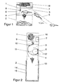
- the rattrap may be divided into two parts, viz. a catching unit 1 and an underlying killing unit 2.
- the catching unit 1 is formed with a longitudinal tunnel-shaped compartment 3 defined by the walls of the catching unit and a drop door 4 of curved cross-section. Entrance into the tunnel 3 is obtained via an entrance pipe 5 detachably connected on the end of the catching unit 1.
- a feed dispenser 6 with bait for the rats is provided opposite the entrance opening of the tunnel.
- the length of the tunnel is adapted so that only one rat at a time can be present in it. It is likewise ensured that the rats do not nest in the entrance pipe in that this is provided with side openings.
- the floor is rough, while the passages in general have smooth and/or soft shapes and faces to facilitate the comings and goings of the rats.
- the various functions of the trap are controlled by an electronic control unit 7 which is battery-powered.
- a photoelectric sensor unit recording the presence of a rat is positioned immediately in front of the feed dispenser in the ceiling of the tunnel.
- the sensor unit communicates with the control unit, which is moreover connected to an activator 8 in the form of a small air cylinder, alternatively an electromagnet which is activated by an electronically controlled air valve.
- This air valve operates a hold and release latch 9 for the drop door 4 which is rotatably suspended in the catching unit by a suspension at both ends.
- the activator is driven by compressed air from a carbon dioxide bottle, which is used for killing the rats, as will be explained later.
- the weight of the drop door and its offset suspension axis relative to the centre of gravity are partly adapted so that the drop door, solely by the weight of a rat, rotates instantaneously when the door is released so that the rat falls, or rather is "poured" down into the underlying killing unit 2, and partly so that the door, by its own weight, returns to the starting position likewise instantaneously.
- shock absorbers e.g. rubber mouldings, are provided on the points of impact.
- the collection and killing unit 2 consists of a box 11 with an opening at the top defined by the drop door 4 and a box- or drawer-shaped insert 12 for the falling rats.
- the insert 12 may be pulled out from one end of the killing unit and may be lined with a plastics bag 13 for collecting the dead rats so that these may be collected and discharged in a packaged state. Thus, direct contact with the animals is avoided.
- the insert is shown here as a pull-out drawer, but may also be constructed as a tilting drawer.
- the drawer may be totally superfluous.
- the catching unit is pivotally connected with the killing unit or may be lifted off, the actual killing unit may be provided with a collection bag or other form of disposable insert.
- Carbon dioxide from a pressure bottle 16 with liquid carbon dioxide is used for killing the rats.
- the carbon dioxide bottle 16 is arranged in the catching unit, from which a pipe leads down into the killing unit via a reduction and control valve and terminates at a distance above the bottom in the insert 12. Since carbon dioxide is heavier than atmospheric air, it will settle on the bottom of the insert that is filled about 70%, which has been found sufficient by experience to anaesthetize a rat within quite few seconds and subsequently kill it. As the rat falls down, the carbon dioxide will be stirred up in the entire chamber below the drop door, which promotes quick anaesthetization of the rat.
- the electronic control unit 7, which operates the control valve, may be set by a timer to replenish the insert at regular intervals. One replenishment per 24 hours has been found to be sufficient.
- the rattrap shown in fig. 3 of the drawing is constructed in basically the same manner as the trap described previously, the difference being the structure of the drop door which is here constructed as two downwardly pivotable flaps 17, each hinged at the outer side.
- the same reference numerals as above are used for the same parts.
- the door may be constructed as a sliding door which is pulled aside.
- Figs. 4 and 5 of the drawing show an embodiment of the trap of the invention which differs from the two preceding ones in that a separate chamber 18 is provided at the side of the killing chamber 13, said separate chamber being capable of accommodating gas bottle, valve and electronics.
- the upper part 1 has a drop door 4, feed dispenser and sensor unit in the same manner as in the example shown in figs. 1 and 2.
- the upper part 1 is hinged 19 to the lower part 2 at the opposite end of the entrance, so that it can tilt forwardly, and a closing buckle 20 for locking to the lower part 2 is arranged at the other end.
- Bowl-shaped carrier handles 21 facilitating the handling of the trap are secured in recesses in the sides.
- the outer wall 22 of the "technical equipment room” 18 is hinged 23 at the underside about a longitudinal axis so that the wall may be pivoted down. In the closed position, the wall is kept in position in that the roof part has an upright flap which grips behind the outer wall 25 of the upper part 1. To allow opening, the upper part 1 must thus first be pivoted forwards to release the outer wall 22.
- the drop door 4 opens, this may be equipped with an opening mechanism, as shown in fig. 6.
- the underside of the door mounts a block 27 capable of cooperating with a release pawl 28.
- the mutual engagement faces are toothed or are otherwise provided with a frictional surface, so that the pawl holds the drop door in the starting position with certainty, as shown in the drawing.
- An air cylinder 29 connected with the gas bottle serves to release the pawl. Activation of the cylinder causes its piston 30 to affect the pawl on the underside of its protruding nose portion 31 so that the pawl pivots upwards.
- the end of the pawl is connected by a pull wire 21 with the underside of the drop door so that the drop door is activated positively for rotation when the pawl is released.
- a stop 33 is arranged to limit the movement of the pawl. The stop is arranged so that the pawl automatically falls back to the starting position, and relatively quickly, in which it engages the engagement face on the block.
- the pivot point of the pawl is arranged above its centre of gravity, just as the point of attack of the pull wire is arranged on the other side of the pivot point of the drop door.
- a device for watching whether rats or mice are present in a given area may be formed by the upper part 1 of the trap where the activation of the drop door is disconnected.
- a special device may be made for the purpose, i.e. with an entrance chamber, a feed device and an electronic unit, including sensor unit and indicator.
- the carbon dioxide bottle is placed in the catching unit, alternatively it may be placed in the killing unit as shown in the last example, where the lower position inter alia contributes to greater standing stability of the trap.
- the invention thus provides an effective trap with an animal ethical killing form owing to its lenient treatment of the vermins.
Abstract
Description
Claims (13)
- A method in connection with the extermination of particularly rats, mice and similar animals by catching and optionally subsequent killing of these in a trap of the type wherein the animals are caught in a separate chamber (2, 13) and wherein the animals are guided into the chamber via an entrance device (4; 17) connected with an activation mechanism (7, 9, 10) which may be released by an animal via a detection unit (8) when the animal is present on the entrance device, characterized in that a number of animals are allowed to pass the detection unit (9) before the entrance device (4; 17) is activated.
- A method according to claim 1, characterized by comprising killing the animals trapped in the chamber by means of gas, preferably carbon dioxide.
- A method according to claim 1 or 2, characterized in that the animals are fed in the device, preferably at the entrance.
- A device for use in connection with the extermination of particularly rats, mice and similar animals and of the type comprising a separate chamber (2, 13) in which the animals are caught and, in the entrance passages for the animals in the trap, an entrance device (4; 17) through which the animals may be guided into the chamber, an activation mechanism (7, 9, 10) for activating the entrance device, a detection unit (8) for recording animals in the trap, said detection unit communicating with the activation mechanism to release the entrance device, characterized in that the detection unit and/or the activation mechanism (8-10) is arranged such that the entrance device (4; 17) is released after a number of animals have passed the detection device (8).
- A device according to claim 4, characterized in that it comprises means for killing the animals by gas, preferably carbon dioxide.
- A device according to claim 4 or 5, characterized in that an animal feed site (6), where they can eat, is provided after the passage of the animals of the detection unit.
- A device according to claims 4 and 6, characterized in that the feed site is arranged in association with the drop door (4; 17) so that, standing on the drop door, they can eat the feed.
- A device according to claim 4 or 5, characterized in that the detection unit is a touchfree, passive detection unit (8), e.g. an optoelectric sensor.
- A device according to claim 4, characterized in that the entrance device is constructed as a self-closing drop door (4; 17).
- A device according to claim 9, characterized in that the drop door (4) is formed with a curved cross-section and is suspended (11) rotatably about a longitudinal axis so that the door, when activated, can rotate, preferably solely by the weight of an animal, in that the axis of rotation of the drop door is offset relatively to the centre of gravity of the door, so that an animal present on the door falls down into the chamber for storage and optional killing.
- A device according to claim 4, wherein the animals are killed by a gas heavier than air, preferably carbon dioxide, characterized in that, in the use of the trap, the killing chamber (2, 13) is constantly, at least partly, filled with the gas in a sufficient concentration to kill the animals and also preferably arranged such that the killing chamber (2, 13) is replenished with gas at regular intervals.
- A device according to claim 11, characterized in that the killing chamber (2) is lined with a preferably gas-tight plastics bag (13), said chamber being preferably provided with a drawer in which the bag is placed.
- A device according to one of claims 4 to 12, characterized in that it is constructed as two interconnected main parts, viz. a catching unit (1) with a drop door (4; 17) and containing the vital mechanical/electronic parts in general and a unit consisting of the chamber (2) for storage and optional killing.
Priority Applications (1)
| Application Number | Priority Date | Filing Date | Title |
|---|---|---|---|
| SI9830524T SI1018865T1 (en) | 1997-04-29 | 1998-04-29 | A method and device for trapping rats, mice and the like |
Applications Claiming Priority (3)
| Application Number | Priority Date | Filing Date | Title |
|---|---|---|---|
| DK47697 | 1997-04-29 | ||
| DK47697 | 1997-04-29 | ||
| PCT/DK1998/000168 WO1998048620A1 (en) | 1997-04-29 | 1998-04-29 | A method and device for trapping rats, mice and the like |
Publications (3)
| Publication Number | Publication Date |
|---|---|
| EP1018865A1 EP1018865A1 (en) | 2000-07-19 |
| EP1018865B1 EP1018865B1 (en) | 2003-07-09 |
| EP1018865B9 true EP1018865B9 (en) | 2004-08-11 |
Family
ID=8093986
Family Applications (1)
| Application Number | Title | Priority Date | Filing Date |
|---|---|---|---|
| EP98919083A Expired - Lifetime EP1018865B9 (en) | 1997-04-29 | 1998-04-29 | A method and device for trapping rats, mice and the like |
Country Status (10)
| Country | Link |
|---|---|
| US (1) | US6088948A (en) |
| EP (1) | EP1018865B9 (en) |
| JP (1) | JP3963486B2 (en) |
| AT (1) | ATE244503T1 (en) |
| AU (1) | AU7205598A (en) |
| DE (1) | DE69816314T2 (en) |
| DK (1) | DK1018865T3 (en) |
| ES (1) | ES2202842T3 (en) |
| PT (1) | PT1018865E (en) |
| WO (1) | WO1998048620A1 (en) |
Families Citing this family (52)
| Publication number | Priority date | Publication date | Assignee | Title |
|---|---|---|---|---|
| US6344745B1 (en) * | 1998-11-25 | 2002-02-05 | Medrad, Inc. | Tapered birdcage resonator for improved homogeneity in MRI |
| US6718688B2 (en) * | 2000-10-30 | 2004-04-13 | John E. Garretson | Automatic roach trap having disposable container therein |
| US7530195B2 (en) * | 2002-10-02 | 2009-05-12 | Ratco Aps | Electrocution animal trap with a sender |
| US6836999B2 (en) * | 2003-05-05 | 2005-01-04 | Woodstream Corporation | CPU-controlled, rearming, high voltage output circuit for electronic animal trap |
| US6938368B2 (en) * | 2003-10-21 | 2005-09-06 | Gary D. Guidry | Weight adjustable rodent trap |
| US6865843B1 (en) * | 2003-10-23 | 2005-03-15 | Charles Jordan, Sr. | Portable electrical mouse trap |
| US20050235553A1 (en) * | 2004-04-27 | 2005-10-27 | Rail Kenneth D | Rodent elimination system |
| US20060026893A1 (en) * | 2004-08-03 | 2006-02-09 | Sears Richard B | Rodent trap |
| US20060032110A1 (en) * | 2004-08-16 | 2006-02-16 | Keng-Ming Yang | Trapping device |
| CN100350837C (en) * | 2004-11-23 | 2007-11-28 | 徐会林 | Long effective successional method for catching mouse |
| US20060156615A1 (en) * | 2005-01-18 | 2006-07-20 | Brian Hale | Snap trap enclosure for trapping and killing rodents |
| CN101442906A (en) * | 2005-01-23 | 2009-05-27 | 哈梅林有限公司 | Device for managing rodent |
| US20070245617A1 (en) * | 2006-04-21 | 2007-10-25 | Deibert Ronald H | Electronic multiple-use vermin trap and method |
| CN101516184B (en) * | 2006-09-22 | 2014-10-22 | 埃科莱布有限公司 | Versatile pest station with interchangeable inserts |
| DK177937B1 (en) * | 2006-10-19 | 2015-01-19 | Paf Holding Aps | rat trap |
| US20100170074A1 (en) * | 2007-02-26 | 2010-07-08 | PAF Holdings ApS | Rat trap |
| US20080236023A1 (en) * | 2007-03-28 | 2008-10-02 | Ecolab Inc. | Automated pest-trapping device |
| NZ554311A (en) * | 2007-04-02 | 2009-10-30 | Contimo Ltd | A pest control device |
| HUE026990T2 (en) * | 2008-02-06 | 2016-08-29 | Wisecon As | A rat trap |
| CA2621101C (en) * | 2008-03-05 | 2009-10-27 | Animal Deterrent Systems Ltd. | Multiple-use vermin electrocution trap and method |
| NZ591817A (en) * | 2008-09-22 | 2012-08-31 | Basf Corp | Live trap for trapping rodents with two interchangeable trap mechanisms |
| GB0904836D0 (en) * | 2009-03-20 | 2009-05-06 | Biotronics Ltd | Vertebrate trap |
| US7913447B1 (en) * | 2009-03-23 | 2011-03-29 | Jabro Bahjat S | Smart and multiple mouse trap |
| US8695274B2 (en) * | 2009-09-24 | 2014-04-15 | Woodstream Corporation | Single use hermetically sealing mousetrap with internal carbon dioxide killing mechanism |
| US8291637B2 (en) * | 2009-09-25 | 2012-10-23 | B&G Equipment Company | Rodent trap including presence indicator mechanism |
| KR100943838B1 (en) * | 2009-10-22 | 2010-02-23 | 주식회사 엠피코씨엠 | Electrical sharing box of underground transmission line having a device for capturing a mouse |
| US9101126B2 (en) * | 2010-01-11 | 2015-08-11 | Jager Pro, Llc | Remote control gate release for trap enclosure |
| US10070642B2 (en) * | 2011-03-02 | 2018-09-11 | Woodstream Corporation | Mousetrap with disposable, hermetically sealing cartridge and internal high-voltage killing mechanism |
| EP2852281A4 (en) * | 2012-05-21 | 2016-02-24 | Daryl Pinder | A self resetting pest trap |
| WO2013177652A1 (en) * | 2012-05-29 | 2013-12-05 | Animal Deterrent Systems Ltd. | Multiple-use vermin trap apparatus, method and system |
| WO2014183014A2 (en) * | 2013-05-09 | 2014-11-13 | Aviantronics, Llc | Species specific extermination device |
| US20150033614A1 (en) * | 2013-07-31 | 2015-02-05 | James Allen Allbright, JR. | Rat Trap Wheel Chock |
| GB2521399B (en) * | 2013-12-18 | 2016-11-16 | Rentokil Initial Plc | Bait station for pest control |
| US20150201628A1 (en) * | 2014-01-21 | 2015-07-23 | Pulse Needlefree Systems, Inc. | System and method to restrain and provide an inhalant agent to an animal |
| US20160066557A1 (en) * | 2014-09-05 | 2016-03-10 | Ap&G Co., Inc. | Rodent trap having improved apparatus to trap rodents |
| WO2016097993A1 (en) | 2014-12-16 | 2016-06-23 | Apice Srl | An electro-mechanical ecological device, for continuous, even multiple, capture of harmful rodents |
| NL2014626B1 (en) * | 2015-04-13 | 2017-01-25 | Bergwerff Frederik | Device and method for removing mice and rats from food. |
| US10015453B2 (en) * | 2015-08-03 | 2018-07-03 | Michael T. Hobbs | Tunnel camera system |
| US20180317475A1 (en) * | 2015-11-05 | 2018-11-08 | John Michael Redmayne | A trap |
| US10512258B2 (en) * | 2016-01-20 | 2019-12-24 | Joseph Baxter | Animal trap with animal entrance encouraging means |
| SE1650107A1 (en) * | 2016-01-29 | 2017-05-02 | Envac Ab | Rodent trapping and removal method and arrangement |
| DK201600097U4 (en) * | 2016-09-01 | 2017-12-22 | Camro Aps | Børne- og kæledyrssikret giftfri gnaverfælde |
| US10842145B2 (en) | 2017-03-02 | 2020-11-24 | Woodstream Corporation | Self-arming electronic rodent trap and system and method for use thereof |
| CN107372450A (en) * | 2017-08-28 | 2017-11-24 | 徐会林 | Multi-functional continuous mouse catching, hunt device |
| US10085439B1 (en) * | 2018-02-07 | 2018-10-02 | Matthew J. Uhlik | Casino mentality hog trap |
| CN108496947B (en) * | 2018-03-05 | 2021-06-29 | 李先登 | Machine for restraining and trapping multiple mice |
| WO2022104476A1 (en) * | 2020-11-20 | 2022-05-27 | Catch Data Ltd. | Method and apparatus for controlling pest animals |
| KR102533700B1 (en) * | 2021-02-03 | 2023-05-17 | 주식회사 녹인 | Amphibious monitoring devices using decoy lamps |
| NL2027856B1 (en) * | 2021-03-29 | 2022-10-12 | Mega Des Plaagdierbeheersing B V | Animal trap and method of operating the animal trap |
| CN113519495A (en) * | 2021-06-27 | 2021-10-22 | 刘修 | Novel mouse trapping device |
| KR102605648B1 (en) * | 2021-07-20 | 2023-11-22 | 국립생태원 | Manchurian weasel trap |
| US11730160B1 (en) | 2022-04-29 | 2023-08-22 | Nick Suteerawanit | Electric multi-catch rodent trap |
Family Cites Families (9)
| Publication number | Priority date | Publication date | Assignee | Title |
|---|---|---|---|---|
| US4641456A (en) * | 1985-01-14 | 1987-02-10 | Robert Boharski | Mouse trap |
| US4741121A (en) * | 1986-03-13 | 1988-05-03 | Andrew J. Pratscher | Gas chamber animal trap |
| CH670709A5 (en) * | 1986-04-24 | 1989-06-30 | Univ Moskovsk | |
| CH672709A5 (en) * | 1987-06-12 | 1989-12-29 | Paul Degen Kunz | Mouse trap with capacitive sensor - uses sensor to control release electromagnet for hinged plate above smooth-side container |
| US4890415A (en) * | 1988-12-19 | 1990-01-02 | Fressola Alfred A | Timing device for live animal traps |
| NL8901035A (en) * | 1989-04-25 | 1990-11-16 | Ecotronics Bv | SYSTEM FOR THE REGISTRATION AND / OR CONTROL OF RODENTS SUCH AS MICE AND RATS. |
| US5265371A (en) * | 1992-06-22 | 1993-11-30 | Mccuistion Iii Alvin J | Box shaped rat trap |
| DE19537851C2 (en) * | 1995-10-11 | 1997-07-17 | Franz J Gschwind | Device for catching and killing small rodents, especially rats |
| US5815982A (en) * | 1996-11-14 | 1998-10-06 | Garretson; John E. | Automatic insect trap using infrared beam of radiation |
-
1998
- 1998-04-29 AU AU72055/98A patent/AU7205598A/en not_active Abandoned
- 1998-04-29 JP JP54651198A patent/JP3963486B2/en not_active Expired - Fee Related
- 1998-04-29 DE DE69816314T patent/DE69816314T2/en not_active Expired - Fee Related
- 1998-04-29 WO PCT/DK1998/000168 patent/WO1998048620A1/en active IP Right Grant
- 1998-04-29 PT PT98919083T patent/PT1018865E/en unknown
- 1998-04-29 AT AT98919083T patent/ATE244503T1/en not_active IP Right Cessation
- 1998-04-29 ES ES98919083T patent/ES2202842T3/en not_active Expired - Lifetime
- 1998-04-29 DK DK98919083T patent/DK1018865T3/en active
- 1998-04-29 EP EP98919083A patent/EP1018865B9/en not_active Expired - Lifetime
-
1999
- 1999-10-28 US US09/428,653 patent/US6088948A/en not_active Expired - Fee Related
Also Published As
| Publication number | Publication date |
|---|---|
| ES2202842T3 (en) | 2004-04-01 |
| DE69816314T2 (en) | 2004-05-13 |
| EP1018865A1 (en) | 2000-07-19 |
| JP2001523100A (en) | 2001-11-20 |
| US6088948A (en) | 2000-07-18 |
| DK1018865T3 (en) | 2003-10-13 |
| ATE244503T1 (en) | 2003-07-15 |
| JP3963486B2 (en) | 2007-08-22 |
| AU7205598A (en) | 1998-11-24 |
| WO1998048620A1 (en) | 1998-11-05 |
| PT1018865E (en) | 2003-11-28 |
| EP1018865B1 (en) | 2003-07-09 |
| DE69816314D1 (en) | 2003-08-14 |
Similar Documents
| Publication | Publication Date | Title |
|---|---|---|
| EP1018865B1 (en) | A method and device for trapping rats, mice and the like | |
| US7540109B2 (en) | Humane trap for small animals | |
| US20220330539A1 (en) | Rodent traps | |
| US20170265451A1 (en) | Self Resetting Pest Trap | |
| US4144667A (en) | Self-locking disposable rodent trap | |
| US4578892A (en) | Rodent trap | |
| US20100115826A1 (en) | Pest control device | |
| WO2007121554A1 (en) | Multiple-use vermin trap and method | |
| US4706407A (en) | Animal trap | |
| AU2012366780A1 (en) | Improved animal trap | |
| US20050279015A1 (en) | Awesome rat & mouse trap | |
| US20170112119A1 (en) | Baited Animal Trap | |
| US20200288696A1 (en) | Rodent Trap | |
| CA1260268A (en) | Rodent trap | |
| US3688432A (en) | Animal trap | |
| US5502918A (en) | Mousetrap for catching mice live | |
| US3828460A (en) | Rodent trap | |
| US4379374A (en) | Rodent trap | |
| US11678654B1 (en) | Trap door multi-catch rodent trap | |
| JPH0560285U (en) | Animal capture device | |
| NZ510131A (en) | Apparatus for treating or killing animals | |
| SI20406A (en) | Trap for rodents |
Legal Events
| Date | Code | Title | Description |
|---|---|---|---|
| PUAI | Public reference made under article 153(3) epc to a published international application that has entered the european phase |
Free format text: ORIGINAL CODE: 0009012 |
|
| 17P | Request for examination filed |
Effective date: 19991011 |
|
| AK | Designated contracting states |
Kind code of ref document: A1 Designated state(s): AT BE CH CY DE DK ES FI FR GB GR IE IT LI LU MC NL PT SE |
|
| AX | Request for extension of the european patent |
Free format text: AL PAYMENT 19991011;LT PAYMENT 19991011;LV PAYMENT 19991011;MK PAYMENT 19991011;RO PAYMENT 19991011;SI PAYMENT 19991011 |
|
| 17Q | First examination report despatched |
Effective date: 20020129 |
|
| GRAH | Despatch of communication of intention to grant a patent |
Free format text: ORIGINAL CODE: EPIDOS IGRA |
|
| GRAH | Despatch of communication of intention to grant a patent |
Free format text: ORIGINAL CODE: EPIDOS IGRA |
|
| GRAA | (expected) grant |
Free format text: ORIGINAL CODE: 0009210 |
|
| AK | Designated contracting states |
Designated state(s): AT BE CH CY DE DK ES FI FR GB GR IE IT LI LU MC NL PT SE |
|
| AX | Request for extension of the european patent |
Extension state: AL LT LV MK RO SI |
|
| PG25 | Lapsed in a contracting state [announced via postgrant information from national office to epo] |
Ref country code: CY Free format text: LAPSE BECAUSE OF FAILURE TO SUBMIT A TRANSLATION OF THE DESCRIPTION OR TO PAY THE FEE WITHIN THE PRESCRIBED TIME-LIMIT Effective date: 20030709 |
|
| REG | Reference to a national code |
Ref country code: GB Ref legal event code: FG4D |
|
| REG | Reference to a national code |
Ref country code: CH Ref legal event code: EP |
|
| REF | Corresponds to: |
Ref document number: 69816314 Country of ref document: DE Date of ref document: 20030814 Kind code of ref document: P |
|
| REG | Reference to a national code |
Ref country code: IE Ref legal event code: FG4D |
|
| REG | Reference to a national code |
Ref country code: SE Ref legal event code: TRGR |
|
| REG | Reference to a national code |
Ref country code: CH Ref legal event code: NV Representative=s name: KELLER & PARTNER PATENTANWAELTE AG |
|
| REG | Reference to a national code |
Ref country code: GR Ref legal event code: EP Ref document number: 20030404065 Country of ref document: GR |
|
| LTIE | Lt: invalidation of european patent or patent extension |
Effective date: 20030709 |
|
| REG | Reference to a national code |
Ref country code: ES Ref legal event code: FG2A Ref document number: 2202842 Country of ref document: ES Kind code of ref document: T3 |
|
| PG25 | Lapsed in a contracting state [announced via postgrant information from national office to epo] |
Ref country code: LU Free format text: LAPSE BECAUSE OF NON-PAYMENT OF DUE FEES Effective date: 20040429 |
|
| PG25 | Lapsed in a contracting state [announced via postgrant information from national office to epo] |
Ref country code: MC Free format text: LAPSE BECAUSE OF NON-PAYMENT OF DUE FEES Effective date: 20040430 |
|
| PLBE | No opposition filed within time limit |
Free format text: ORIGINAL CODE: 0009261 |
|
| STAA | Information on the status of an ep patent application or granted ep patent |
Free format text: STATUS: NO OPPOSITION FILED WITHIN TIME LIMIT |
|
| ET | Fr: translation filed | ||
| 26N | No opposition filed |
Effective date: 20040414 |
|
| REG | Reference to a national code |
Ref country code: SI Ref legal event code: IF |
|
| PGFP | Annual fee paid to national office [announced via postgrant information from national office to epo] |
Ref country code: IE Payment date: 20070417 Year of fee payment: 10 |
|
| PGFP | Annual fee paid to national office [announced via postgrant information from national office to epo] |
Ref country code: PT Payment date: 20070418 Year of fee payment: 10 |
|
| PGFP | Annual fee paid to national office [announced via postgrant information from national office to epo] |
Ref country code: CH Payment date: 20070419 Year of fee payment: 10 |
|
| PGFP | Annual fee paid to national office [announced via postgrant information from national office to epo] |
Ref country code: AT Payment date: 20070420 Year of fee payment: 10 |
|
| PGFP | Annual fee paid to national office [announced via postgrant information from national office to epo] |
Ref country code: SE Payment date: 20070424 Year of fee payment: 10 |
|
| PGFP | Annual fee paid to national office [announced via postgrant information from national office to epo] |
Ref country code: FI Payment date: 20070426 Year of fee payment: 10 Ref country code: ES Payment date: 20070426 Year of fee payment: 10 Ref country code: NL Payment date: 20070426 Year of fee payment: 10 |
|
| PGFP | Annual fee paid to national office [announced via postgrant information from national office to epo] |
Ref country code: DK Payment date: 20070427 Year of fee payment: 10 |
|
| PGFP | Annual fee paid to national office [announced via postgrant information from national office to epo] |
Ref country code: DE Payment date: 20070516 Year of fee payment: 10 |
|
| PGFP | Annual fee paid to national office [announced via postgrant information from national office to epo] |
Ref country code: GB Payment date: 20070423 Year of fee payment: 10 |
|
| PGFP | Annual fee paid to national office [announced via postgrant information from national office to epo] |
Ref country code: IT Payment date: 20070622 Year of fee payment: 10 Ref country code: BE Payment date: 20070424 Year of fee payment: 10 |
|
| PGFP | Annual fee paid to national office [announced via postgrant information from national office to epo] |
Ref country code: FR Payment date: 20070425 Year of fee payment: 10 |
|
| PGFP | Annual fee paid to national office [announced via postgrant information from national office to epo] |
Ref country code: GR Payment date: 20070404 Year of fee payment: 10 |
|
| BERE | Be: lapsed |
Owner name: *RONNAU PER Effective date: 20080430 |
|
| REG | Reference to a national code |
Ref country code: PT Ref legal event code: MM4A Free format text: LAPSE DUE TO NON-PAYMENT OF FEES Effective date: 20081029 |
|
| REG | Reference to a national code |
Ref country code: CH Ref legal event code: PL |
|
| REG | Reference to a national code |
Ref country code: DK Ref legal event code: EBP |
|
| EUG | Se: european patent has lapsed | ||
| GBPC | Gb: european patent ceased through non-payment of renewal fee |
Effective date: 20080429 |
|
| NLV4 | Nl: lapsed or anulled due to non-payment of the annual fee |
Effective date: 20081101 |
|
| PG25 | Lapsed in a contracting state [announced via postgrant information from national office to epo] |
Ref country code: PT Free format text: LAPSE BECAUSE OF NON-PAYMENT OF DUE FEES Effective date: 20081029 Ref country code: NL Free format text: LAPSE BECAUSE OF NON-PAYMENT OF DUE FEES Effective date: 20081101 Ref country code: LI Free format text: LAPSE BECAUSE OF NON-PAYMENT OF DUE FEES Effective date: 20080430 Ref country code: DE Free format text: LAPSE BECAUSE OF NON-PAYMENT OF DUE FEES Effective date: 20081101 Ref country code: CH Free format text: LAPSE BECAUSE OF NON-PAYMENT OF DUE FEES Effective date: 20080430 |
|
| REG | Reference to a national code |
Ref country code: FR Ref legal event code: ST Effective date: 20081231 |
|
| REG | Reference to a national code |
Ref country code: IE Ref legal event code: MM4A |
|
| PG25 | Lapsed in a contracting state [announced via postgrant information from national office to epo] |
Ref country code: FI Free format text: LAPSE BECAUSE OF NON-PAYMENT OF DUE FEES Effective date: 20080429 Ref country code: AT Free format text: LAPSE BECAUSE OF NON-PAYMENT OF DUE FEES Effective date: 20080429 |
|
| REG | Reference to a national code |
Ref country code: SI Ref legal event code: KO00 Effective date: 20090108 |
|
| PG25 | Lapsed in a contracting state [announced via postgrant information from national office to epo] |
Ref country code: BE Free format text: LAPSE BECAUSE OF NON-PAYMENT OF DUE FEES Effective date: 20080430 |
|
| PG25 | Lapsed in a contracting state [announced via postgrant information from national office to epo] |
Ref country code: IE Free format text: LAPSE BECAUSE OF NON-PAYMENT OF DUE FEES Effective date: 20080429 Ref country code: FR Free format text: LAPSE BECAUSE OF NON-PAYMENT OF DUE FEES Effective date: 20080430 Ref country code: DK Free format text: LAPSE BECAUSE OF NON-PAYMENT OF DUE FEES Effective date: 20080430 |
|
| REG | Reference to a national code |
Ref country code: ES Ref legal event code: FD2A Effective date: 20080430 |
|
| PG25 | Lapsed in a contracting state [announced via postgrant information from national office to epo] |
Ref country code: GR Free format text: LAPSE BECAUSE OF NON-PAYMENT OF DUE FEES Effective date: 20081104 Ref country code: GB Free format text: LAPSE BECAUSE OF NON-PAYMENT OF DUE FEES Effective date: 20080429 |
|
| PG25 | Lapsed in a contracting state [announced via postgrant information from national office to epo] |
Ref country code: ES Free format text: LAPSE BECAUSE OF NON-PAYMENT OF DUE FEES Effective date: 20080430 |
|
| PG25 | Lapsed in a contracting state [announced via postgrant information from national office to epo] |
Ref country code: IT Free format text: LAPSE BECAUSE OF NON-PAYMENT OF DUE FEES Effective date: 20080429 |
|
| PG25 | Lapsed in a contracting state [announced via postgrant information from national office to epo] |
Ref country code: SE Free format text: LAPSE BECAUSE OF NON-PAYMENT OF DUE FEES Effective date: 20080430 |