EP1042054B1 - Apparatus for electrophoresis - Google Patents
Apparatus for electrophoresis Download PDFInfo
- Publication number
- EP1042054B1 EP1042054B1 EP98960923A EP98960923A EP1042054B1 EP 1042054 B1 EP1042054 B1 EP 1042054B1 EP 98960923 A EP98960923 A EP 98960923A EP 98960923 A EP98960923 A EP 98960923A EP 1042054 B1 EP1042054 B1 EP 1042054B1
- Authority
- EP
- European Patent Office
- Prior art keywords
- tray
- troughs
- electrodes
- electrophoresis apparatus
- electrophoresis
- Prior art date
- Legal status (The legal status is an assumption and is not a legal conclusion. Google has not performed a legal analysis and makes no representation as to the accuracy of the status listed.)
- Expired - Lifetime
Links
Images


Classifications
-
- B—PERFORMING OPERATIONS; TRANSPORTING
- B01—PHYSICAL OR CHEMICAL PROCESSES OR APPARATUS IN GENERAL
- B01D—SEPARATION
- B01D57/00—Separation, other than separation of solids, not fully covered by a single other group or subclass, e.g. B03C
- B01D57/02—Separation, other than separation of solids, not fully covered by a single other group or subclass, e.g. B03C by electrophoresis
-
- G—PHYSICS
- G01—MEASURING; TESTING
- G01N—INVESTIGATING OR ANALYSING MATERIALS BY DETERMINING THEIR CHEMICAL OR PHYSICAL PROPERTIES
- G01N27/00—Investigating or analysing materials by the use of electric, electrochemical, or magnetic means
- G01N27/26—Investigating or analysing materials by the use of electric, electrochemical, or magnetic means by investigating electrochemical variables; by using electrolysis or electrophoresis
- G01N27/416—Systems
- G01N27/447—Systems using electrophoresis
- G01N27/44704—Details; Accessories
-
- G—PHYSICS
- G01—MEASURING; TESTING
- G01N—INVESTIGATING OR ANALYSING MATERIALS BY DETERMINING THEIR CHEMICAL OR PHYSICAL PROPERTIES
- G01N27/00—Investigating or analysing materials by the use of electric, electrochemical, or magnetic means
- G01N27/26—Investigating or analysing materials by the use of electric, electrochemical, or magnetic means by investigating electrochemical variables; by using electrolysis or electrophoresis
- G01N27/416—Systems
- G01N27/447—Systems using electrophoresis
- G01N27/44756—Apparatus specially adapted therefor
- G01N27/44782—Apparatus specially adapted therefor of a plurality of samples
Definitions
- the invention relates to apparatus for the separation of macromolecules by electrophoresis, particularly by isoelectric focusing.
- Two-dimensional (2D) electrophoresis is a useful and well-known separation technique for purifying macromolecules and separating complex macromolecule mixtures, often providing a much higher resolving power than typical electrophoretic separation in one dimension or direction.
- separation is performed under two different conditions or according to two different separation parameters, one in a first direction and the other in a second direction which is usually perpendicular to the first.
- the first dimension of the separation is typically performed in an elongate rod-shaped or strip-shaped gel with migration and separation of macromolecules occurring along the length of the gel.
- the gel is placed along one edge of a slab gel and the electric current is imposed across the both gels in a direction perpendicular or otherwise transverse to the first (elongate) gel. This causes the migration of the macromolecules from each zone of the elongate gel into the slab gel, and the separation of macromolecules within each zone.
- first and second dimension separations can be used for the first and second dimension separations. Separation based on charge or pI can be followed by separation based on molecular weight, for example. Likewise, separation in a gel of one concentration can be followed by separation in a gel of the same material but of another concentration.
- Two-dimensional separations have also been used to create a stepwise change in pH to separate first in a homogeneous gel and then in a pore-gradient gel, to separate in media containing first one protein solubiliser and then another, or in media containing a protein solubiliser first at one concentration and then at another concentration, to separate first in a discontinuous buffer system and then in a continuous buffer system, and to separate first by isoelectric focusing and then by homogeneous or pore gradient electrophoresis.
- Combinations such as these can be used to separate many kinds of macromolecules, including serum or cell proteins, bacterial proteins, non-histone chromatin proteins, ribosomal proteins, mixtures of ribonucleo-proteins and ribosomal proteins, glycoproteins, and nucleic acids.
- US 4,151,065 discloses an electrophoresis apparatus having a removable tray.
- the apparatus is for use with horizontal gel electrophoresis, and is not suitable for running IPGs.
- EP 457526 discloses an electrophoresis apparatus including a removable tray, buffer wells located either end of the tray, and removable electrodes holders.
- the present invention consists in an electrophoresis apparatus for the simultaneous electrophoretic separation of a plurality of component mixtures, the apparatus comprising:
- the tray is provided with the electrodes positioned in the troughs and having electrical terminals positioned at one end of the leads.
- the terminals connect to plugs positioned therein thus allowing the imposing of an electric potential between the leads.
- a principal advantage of the present invention is that it allows the tray to be disposable although trays could be provided for multiple use, if desired.
- any suitable conductive material compatible with electrophoresis could be used as the electrode although clearly cheaper electrodes such s graphite would be preferable to platinum if the tray is to be thrown away after use.
- the tray is fabricated of a heat-transmissive material to permit temperature control of the troughs through the tray.
- the tray comprises 3 to 24, preferably 6 to 18, substantially parallel troughs.
- the troughs are preferably of equal length and each from 6 cm to 20 cm in length. It will be appreciated, however, that the tray may have any number of troughs, and the troughs be any suitable length and depth.
- the apparatus according to the first aspect of the present invention also allows the possibility to stack a plurality of trays and carry out multiple separations simultaneously.
- the trays are removable for loading etc, and then would simply plug in to a suitable frame adapted to receive a number of trays stacked horizontally.
- one power supply could be used for a number of trays.
- each elongate strip of isoelectric focusing medium placed in a trough will be subjected to the electric potential.
- the electrically conductive connecting means may be electrical leads attachable to the electrodes for connecting the electrodes to a suitable power source.
- the present invention consists in an electrophoresis apparatus for the simultaneous electrophoretic separation of a plurality of component mixtures, the apparatus comprising:
- each of the support members has an axis of rotation that is transverse to the parallel troughs.
- the apparatus may further include a means for biasing each the support member into the first position.
- the support members in addition to being rotatably mounted to the frame, may also be movably mounted thereto at a variable distance from each other.
- the tray is fabricated of a heat-transmissive material to permit temperature control of the troughs through the tray.
- the tray comprises 3 to 24, preferably 6 to 18, substantially parallel troughs.
- the troughs are preferably of equal length and each from 6 cm to 20 cm in length.
- the electrically conductive connecting means may be electrical leads attachable to the electrodes for connecting the electrodes to a suitable power source.
- the present invention consists in a method of separating a macromolecule comprising subjecting the macromolecule to electrophoresis in an apparatus according to the first or second aspects of the present invention.
- the tray 11 is shown, held inside a frame 12 by retaining blocks 13.
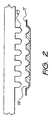
- the tray is shown in transverse cross section in Fig. 2, and contains an array of parallel troughs 14, which are visible from above in Fig. 1 and in profile in Fig. 2.
- Each trough extends almost the entire length of the tray 11, and is long enough to contain a single rod- or strip-shaped gel that will be used as the first dimension separation in two-dimensional electrophoresis.
- the length is otherwise not critical and can vary to accommodate gel strips or rods of various sizes.
- An appropriate length for most applications of this invention will generally range from about 6 cm to about 20 cm.
- the troughs will generally be of equal length.
- each trough is also not critical and can vary.
- An appropriate depth for most applications will generally range from about 0.3 cm to about 3.0 cm, and appropriate width likewise from about 0.3 cm to about 3.0 cm, and appropriate center-to-center spacing from about 0.5 cm to about 3.5 cm. While a curved profile is shown in Fig. 2, other profiles such as a rectangular profile can also be used.
- the tray depicted in the drawings contains six troughs, but the invention extends to trays with any plurality of troughs. For most applications, the appropriate number of troughs will range from 3 to 24, and preferably from 6 to 18.
- the tray 11 is designed as a disposable item intended for a single use.
- the tray also serves as a heat-transfer element to allow temperature control of the gel strips and liquids that are placed in the troughs.
- the tray can thus, for example, be a thermoformed plastic component whose walls are thin enough to permit heat transfer to and from each trough to a temperature control device such as a heating element or heat sink contacting the underside of the tray.
- the temperature control device although not shown in the drawings, can be incorporated into the structure of the frame 12.
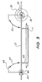
- pair of rails 21, 22, spanning the length of the frame interior and running parallel to each other and to the troughs of the tray 11.
- Each rail is electrically conductive and is electrically connected to banana plugs 23, 24 or other electrical connectors on the frame exterior.
- a pair of transverse support members 25, 26 are mounted across the two rails 21, 22 in both a longitudinally slidable and axially rotatable manner.
- Each support member is longitudinally and independently slidable in the directions of the arrows 27, 28 of Fig. 1, and is rotatable about its axis in the directions of the arrows 29, 30 shown in Fig. 3.
- Set screws 33, 34, 35, 36 can be tightened to fix the support members in any selected location along the rails 21, 22 without inhibiting the axial rotation of the support members 25, 26. Rotation of each support member is facilitated by knobs 37, 38 for manual rotation by the operator. Each support member is also equipped with a spring (one of which 39 is shown in Fig. 3) to bias the support member toward the inward position.
- each rotatable support member Attached to each rotatable support member is a smaller frame 41, 42, each of these smaller frames rotating with the rotation of its respective support member. Extending from each of these smaller frames is a series of electrodes 43 (the electrodes of one frame are visible in Fig. 2) in an array corresponding to the troughs 14 of the tray 11. When the tray 11 is in place in the outer frame 12 and the smaller frames 41, 42 are rotated inward such that electrodes 43 are lowered, the electrodes are aligned with the troughs. The widths of the electrodes and the spacings between them are selected so that one lead will extend into each trough and contact the gel or IPG strip contained in that trough. The electrodes 43 and the support bar 44 from which they extend can thus be shaped like the teeth of a comb.
- each of the two arrays of electrodes is separately supplied by one of the two exterior plugs 23, 24.
- This can be accomplished in any of various ways.
- the rails 21, 22, the rotatable support arms 25, 26, the smaller frames 41, 42, and the electrodes 43 (the teeth of the comb) are all electrically conductive.
- the sliding blocks 46, 47, 48, 49 that join the rotatable support arms 25, 26 to the rails 21, 22 are non-conductors.
- Affixed to two of the sliding blocks 33, 36 are movable fittings 50, 51 that are of electrically conductive material. Each of these fittings is slidable in the direction indicated by the arrows 52, 53.
- Biasing of the electrodes into the troughs to insure proper and uniform electrical contact is as described above achieved by spring loading the rotatable arms.
- An alternative to the use of springs or similar devices is the use a gravitational force by using a biased weight distribution in the rotatable arm.
- the smaller frames 41, 42 to which the electrodes are mounted can also support sample receptacles, one aligned with each trough to supply sample mixtures to the troughs.
- the apparatus can also contain a lid or cover to protect the gels and liquids contained in the troughs and to prevent operator contact with exposed electric leads.
- the tray 11 can be inserted into the outer frame from above or slid into position by side entry into the outer frame.
- the retaining blocks 13 can be replaced by any structure affixed to the outer frame or any shape of the frame that will accomplish a similar purpose of stabilising the position of the tray relative to the rotatable support arms.
- the troughs can contain removable pins or other barriers to ensure proper positioning of the gels, particularly when the gels are shorter than the troughs.
- the apparatus of this invention can be used for any type of gel strip, the invention is particularly useful for gels with immobilised functional groups distributed along its length for isoelectric focusing.
- the immobilised groups form a pH gradient by virtue of a charge distribution already present in the groups or the capability of being charged to form a pH gradient.
- the pH gradient can be formed by carrier ampholytes that are not immobilised in the strip matrix.
- the matrix may be a solid support material such as a granule or fibrous, or membrane material, or it may be a gel.
- matrix materials are polyacrylamide, cellulose, agarose, dextran, polyvinylalcohol, starch, silicon gel, acryloyl amino ethoxyl ethanol (AAEE), and polymers of styrene divinyl benzene, as well as combinations of these materials.
- Examples of positively charged or chargeable groups are amino groups and other nitrogen containing groups.
- Examples of negatively charged or chargeable groups are carboxylic acid groups, sulphonic acid groups, boronic acid groups, and phosphonic or phosphoric acid groups, as well as esters of these acids.
- Immobilisation of the groups on the matrix can be achieved by covalent bonding or any other means that will secure the positions of the groups and prevent their migration under the influence of an electric field or due to the movement of fluids or solutes through the matrix.
- a preferred means of incorporating charged groups into a polymeric gel matrix is by copolymerising charged monomers or charged crossing agents with the gel monomers.
- the concentration of the groups will preferably vary in a monotonically increasing or decreasing manner to form an immobilised pH gradient suitable for isoelectric focusing.
- IPG strips that are made of gels often contain a backing to secure the dimensional integrity of the gel.
- the backing is generally fluid-impermeable and electrically nonconductive.
- the IPG strip is generally supplied in dry form and requires rehydration prior to use. This is conveniently achieved by placing the strip in contact with the sample solution which serves as the rehydrating agent. Rehydration can be performed in the apparatus of this invention in the troughs themselves, while the electrical electrodes are raised above the troughs.
- IPG strips with backing are best rehydrated with the gel side facing down (i.e., the backing facing up).
- the troughs of the tray are preferably sufficiently deep that each IPG strip can be rehydrated with a different sample solution without risking cross contamination from adjacent sample solutions. Once rehydrated, the strips can be separated from the trays and stored frozen until ready for use.
- the strip is preferably turned over to expose its gel side for contact with the electrodes.
- the need to turn the strips over can be eliminated by providing an auxiliary means for electrical contact between the gel and the electrode, recognising that the electric potential will not extend through the backing.
- One means of achieving this is to provide each strip with a hole at each end and to place a wick, in the form of a piece of soft paper or similar absorbent material soaked with a conductive liquid, on top of the strip over the hole. The hole in the strip will fill with conductive liquid, and the wick will ensure electrical contact between the electrode and the liquid occupying the hole (and hence the gel on the underside of the strip).
- the remaining space in the troughs above the gel strips can be filled with paraffin oil or a similar electrically nonconductive liquid, to prevent the evaporation of moisture from the gel during electrophoresis.
- the electric potential is applied to the leads, and each solute migrates to a position along the length of the gel where the gel pH is equal to the isoelectric point of the solute.
- the solutes are separated in this the electric potential is removed, and the support arms supporting the electrodes are rotated away from the troughs.
- the tray is then removed from the frame, the protective paraffin oil is poured out, and the gel strips are removed from the troughs.
- the gel strips can be equilibrated in the troughs for the second stage of the two-dimensional separation.
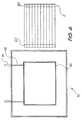
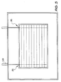
- FIG 4 shows a variant of the invention in which permanent electrodes 60 are incorporated in the disposable tray 11.
- the apparatus generally indicated at 70 includes a frame or holder 80 for receiving the tray 11 and the electrode connections 82 connect to the electrodes 60 at contact points 86 as is best seen in Figure 5.
- the electrode connections are connected to plugs 84 for connection to a power supply.
- Figure 6 shows a yet further embodiment in which the apparatus provides a stack of cells 90 supported on frames 92 one above the other. Each cell 90 is removable from the stack for loading and simply plugs into an electrode connection 94 allowing a single power supply to be used for a number of units.
- the apparatus of this invention lends itself well to automation, with such actions as the insertion of the tray, the addition of the paraffin oil, the lowering of the electrodes, the imposition of the electric potential for a preselected period of time, the raising of the electrodes, and the release of the tray, all controlled by a programmed sequence.
Description
Claims (11)
- An electrophoresis apparatus for the simultaneous electrophoretic separation of a plurality of component mixtures, the apparatus comprising:a tray (11) which is detatchable from and removable from the apparatus, the tray (11) defining a plurality of troughs (14), each trough (14) being shaped to retain an elongate strip of isoelectric focusing medium and sufficient liquid to immerse the elongate strip;a frame (12) to retain the tray (10) in a predetermined position;a pair of support bars (44) adapted to be positioned at or near each and of the tray, each support bar (44) supporting a plurality of depending electrodes (43) arranged such that each electrode (43) is aligned with and locates in each trough (14) of the tray when the tray is in the predetermined position, the electrodes (43) being located near the respective ends of the tray (11); andelectrically conductive connection means for connecting to a means for imposing an electric potential between the electrodes on one support bar and the electrodes on the other support bar.
- An electrophoresis apparatus as claimed in claim 1 characterised in that the tray (11) is provided with the electrodes positioned in the troughs (14) and having electrical terminals positioned at one end of the leads whereby when the tray is placed in the frame, the terminals connect to plugs (23, 24) positioned therein thus allowing the imposing of an electric potential between the leads.
- An electrophoresis apparatus as claimed in any preceding claim characterised in that the tray (11) is fabricated of a beat-transmissive material to permit temperature control of the troughs through the tray.
- An electrophoresis apparatus as claimed in any preceding claim characterised in that the tray (11) comprises 3 to 24, substantially parallel troughs (14).
- An electrophoresis apparatus as claimed in any preceding claim characterised in that the troughs (14) are of substantially equal length and from 6 cm to 20 cm in length.
- An electrophoresis apparatus according to any preceding claim:wherein each support bar (44) is rotatably mounted to the frame via a support member (25, 26) such that when the tray is retained therein each support member spans the plurality of troughs; andwherein means (37, 38) are provided for rotating each support member (25, 26) between a first position in which all electrodes (43) thereon extend into the troughs and a second position in which all electrodes thereon are clear of the troughs.
- An electrophoresis apparatus as claimed in claim 6 characterised in that each of the support members (25, 26) has an axis of rotation that is transverse to the parallel troughs (14).
- An electrophoresis apparatus as claimed in claim 6 or claim 7 characterised in that the apparatus further includes a means for biasing (39) each support member into the first position.
- An electrophoresis apparatus as claimed in any one of claims 6 to 8 characterised in that the support members (25, 26) are rotatably mounted to the frame and are also movably mounted thereto at a variable distance from each other.
- A method of separating a macromolecule comprising subjecting the macromolecule to electrophoresis in an apparatus according to any of the preceding claims.
- An electrophoresis apparatus as claimed in claims 1-9 characterised in that the tray (11) comprises 6 to 18, substantially parallel troughs (14).
Applications Claiming Priority (3)
| Application Number | Priority Date | Filing Date | Title |
|---|---|---|---|
| AUPP108697 | 1997-12-23 | ||
| AUPP1086A AUPP108697A0 (en) | 1997-12-23 | 1997-12-23 | Apparatus for electrophoresis |
| PCT/AU1998/001066 WO1999033550A1 (en) | 1997-12-23 | 1998-12-22 | Apparatus for electrophoresis |
Publications (3)
| Publication Number | Publication Date |
|---|---|
| EP1042054A1 EP1042054A1 (en) | 2000-10-11 |
| EP1042054A4 EP1042054A4 (en) | 2001-10-10 |
| EP1042054B1 true EP1042054B1 (en) | 2003-07-23 |
Family
ID=3805368
Family Applications (1)
| Application Number | Title | Priority Date | Filing Date |
|---|---|---|---|
| EP98960923A Expired - Lifetime EP1042054B1 (en) | 1997-12-23 | 1998-12-22 | Apparatus for electrophoresis |
Country Status (7)
| Country | Link |
|---|---|
| US (1) | US6558522B1 (en) |
| EP (1) | EP1042054B1 (en) |
| JP (1) | JP4362011B2 (en) |
| AU (1) | AUPP108697A0 (en) |
| CA (1) | CA2315757C (en) |
| DE (2) | DE1042054T1 (en) |
| WO (1) | WO1999033550A1 (en) |
Families Citing this family (18)
| Publication number | Priority date | Publication date | Assignee | Title |
|---|---|---|---|---|
| US6582392B1 (en) | 1998-05-01 | 2003-06-24 | Ekos Corporation | Ultrasound assembly for use with a catheter |
| US6156182A (en) * | 1998-11-19 | 2000-12-05 | Bio-Rad Laboratories, Inc. | Encapsulated IPG Strips |
| US7517442B1 (en) * | 1999-08-09 | 2009-04-14 | Life Technologies Corporation | Facile method and apparatus for the analysis of biological macromolecules in two dimensions using common and familiar electrophoresis formats |
| AUPQ276099A0 (en) * | 1999-09-10 | 1999-10-07 | Proteome Systems Ltd | Electrophoresis apparatus and a method of using the same |
| AU768741B2 (en) * | 1999-09-10 | 2004-01-08 | Proteome Systems Ltd | Electrophoresis apparatus and a method of using the same |
| FR2805175B1 (en) * | 2000-02-22 | 2002-05-10 | Sebia Sa | COMPOSITIONS FOR USE IN HYDRATION OF ELECTROPHORESIS SUPPORT, FOR IMPROVING ZONE ELECTROPHORESIS |
| ATE445454T1 (en) | 2001-05-10 | 2009-10-15 | Life Technologies Corp | METHOD AND DEVICES FOR ELECTROPHORESIS OF PRE-POURED, HYDRATIZABLE SEPARATION MEDIA |
| US7601251B2 (en) * | 2001-05-10 | 2009-10-13 | Life Technologies Corporation | Methods and apparatus for low resistance electrophoresis of prior-cast, hydratable separation media |
| AU2002359576A1 (en) | 2001-12-03 | 2003-06-17 | Ekos Corporation | Catheter with multiple ultrasound radiating members |
| CA2476493A1 (en) * | 2002-02-19 | 2003-08-28 | Genome Institute Of Singapore | Device for isoelectric focussing |
| US8226629B1 (en) | 2002-04-01 | 2012-07-24 | Ekos Corporation | Ultrasonic catheter power control |
| EP1742046B1 (en) * | 2005-07-07 | 2007-12-12 | Agilent Technologies, Inc. | Lockable electrode for gel electrophoresis device |
| US10182833B2 (en) | 2007-01-08 | 2019-01-22 | Ekos Corporation | Power parameters for ultrasonic catheter |
| US9044568B2 (en) | 2007-06-22 | 2015-06-02 | Ekos Corporation | Method and apparatus for treatment of intracranial hemorrhages |
| US8282803B2 (en) * | 2009-03-25 | 2012-10-09 | Bio-Rad Laboratories, Inc. | Isoelectric focusing tray and electrode assembly for alternate gel strip orientations |
| PL2448636T3 (en) | 2009-07-03 | 2014-11-28 | Ekos Corp | Power parameters for ultrasonic catheter |
| US10888657B2 (en) | 2010-08-27 | 2021-01-12 | Ekos Corporation | Method and apparatus for treatment of intracranial hemorrhages |
| EP3307388B1 (en) | 2015-06-10 | 2022-06-22 | Ekos Corporation | Ultrasound catheter |
Family Cites Families (11)
| Publication number | Priority date | Publication date | Assignee | Title |
|---|---|---|---|---|
| US4151065A (en) * | 1978-01-30 | 1979-04-24 | The Regents Of The University Of California | Horizontal slab gel electrophoresis |
| DE2929478A1 (en) * | 1979-07-20 | 1981-02-05 | Max Planck Gesellschaft | METHOD AND DEVICE FOR CARRYING OUT A ONE AND TWO DIMENSIONAL MICROELECTROPHORESIS |
| US5116483A (en) | 1989-11-06 | 1992-05-26 | Massachusetts Institute Of Technology | Comb for affinity co-electrophoresis |
| US5750015A (en) * | 1990-02-28 | 1998-05-12 | Soane Biosciences | Method and device for moving molecules by the application of a plurality of electrical fields |
| US5104512A (en) | 1990-05-14 | 1992-04-14 | Labintelligence, Inc. | Gel electrophoresis system |
| US5399255A (en) * | 1993-06-21 | 1995-03-21 | Helena Laboratories Corporation | Platform for conducting electrophoresis, and electrophoresis plate for use with the platform |
| GB2284494B (en) | 1993-11-26 | 1998-09-09 | Hitachi Ltd | Distributed shared memory management system |
| JP3190347B2 (en) | 1993-11-29 | 2001-07-23 | 株式会社東レリサーチセンター | Electrophoretic separation device |
| GB2284484B (en) * | 1993-12-03 | 1997-09-17 | Univ London | Gel-matrix electrophoresis |
| US5773645A (en) | 1997-05-05 | 1998-06-30 | Bio-Rad Laboratories, Inc. | Two-dimensional electrophoresis device |
| US5989400A (en) * | 1997-06-09 | 1999-11-23 | Hoefer Pharmacia Biotech, Inc. | Device and method for applying power to gel electrophoresis modules |
-
1997
- 1997-12-23 AU AUPP1086A patent/AUPP108697A0/en not_active Abandoned
-
1998
- 1998-12-22 DE DE1042054T patent/DE1042054T1/en active Pending
- 1998-12-22 US US09/582,260 patent/US6558522B1/en not_active Expired - Lifetime
- 1998-12-22 JP JP2000526288A patent/JP4362011B2/en not_active Expired - Lifetime
- 1998-12-22 EP EP98960923A patent/EP1042054B1/en not_active Expired - Lifetime
- 1998-12-22 DE DE69816661T patent/DE69816661T2/en not_active Expired - Lifetime
- 1998-12-22 WO PCT/AU1998/001066 patent/WO1999033550A1/en active IP Right Grant
- 1998-12-22 CA CA002315757A patent/CA2315757C/en not_active Expired - Lifetime
Also Published As
| Publication number | Publication date |
|---|---|
| AUPP108697A0 (en) | 1998-01-22 |
| JP2002502018A (en) | 2002-01-22 |
| WO1999033550A1 (en) | 1999-07-08 |
| DE69816661D1 (en) | 2003-08-28 |
| CA2315757A1 (en) | 1999-07-08 |
| DE1042054T1 (en) | 2001-06-07 |
| CA2315757C (en) | 2006-05-09 |
| US6558522B1 (en) | 2003-05-06 |
| EP1042054A4 (en) | 2001-10-10 |
| JP4362011B2 (en) | 2009-11-11 |
| EP1042054A1 (en) | 2000-10-11 |
| DE69816661T2 (en) | 2004-04-15 |
Similar Documents
| Publication | Publication Date | Title |
|---|---|---|
| EP1042054B1 (en) | Apparatus for electrophoresis | |
| US5773645A (en) | Two-dimensional electrophoresis device | |
| US4151065A (en) | Horizontal slab gel electrophoresis | |
| US4234400A (en) | Horizontal slab gel electrophoresis | |
| US5972188A (en) | Membrane loader for gel electrophoresis | |
| AU591399B2 (en) | Field-inversion gel electrophoresis | |
| US4889606A (en) | Electrophoresis and transfer for | |
| US4415418A (en) | Gel electrophoresis device and method | |
| US3674678A (en) | Electrophoretic apparatus | |
| US4049534A (en) | Electrophorectic apparatus for elution from preparative gels | |
| US3719580A (en) | Electrophoretic apparatus | |
| US5968331A (en) | Sample holding device for electrophoresis apparatus and sample injection method | |
| EP0614528A1 (en) | Gel electrophoresis sample applicator/retriever | |
| US4622124A (en) | Device for horizontal electroblotting | |
| US20050072678A1 (en) | Apparatus for electrophoresis | |
| US6139709A (en) | Apparatus for producing electrophoresis gels | |
| AU736903B2 (en) | Apparatus for electrophoresis | |
| WO1992008969A1 (en) | Apparatus and method for submerged gel electrophoresis | |
| US4234404A (en) | Horizontal electrophoresis or isoelectric focusing apparatus | |
| US4289596A (en) | Horizontal electrophoresis or isoelectric focusing apparatus and method of using same | |
| WO1996027787A1 (en) | Membrane loader for gel electrophoresis | |
| US3962058A (en) | Flat bed isoelectric focusing device | |
| WO1991010901A1 (en) | Analysis of biological molecule samples | |
| JP2010503869A (en) | Compositions and devices for electrofiltration of molecules | |
| AU2002331457A1 (en) | Apparatus for electrophoresis |
Legal Events
| Date | Code | Title | Description |
|---|---|---|---|
| PUAI | Public reference made under article 153(3) epc to a published international application that has entered the european phase |
Free format text: ORIGINAL CODE: 0009012 |
|
| 17P | Request for examination filed |
Effective date: 20000614 |
|
| AK | Designated contracting states |
Kind code of ref document: A1 Designated state(s): DE FR GB IT |
|
| EL | Fr: translation of claims filed | ||
| DET | De: translation of patent claims | ||
| A4 | Supplementary search report drawn up and despatched |
Effective date: 20010824 |
|
| AK | Designated contracting states |
Kind code of ref document: A4 Designated state(s): DE FR GB IT |
|
| RIC1 | Information provided on ipc code assigned before grant |
Free format text: 7B 01D 57/02 A, 7C 25B 9/00 B, 7G 01N 27/447 B |
|
| 17Q | First examination report despatched |
Effective date: 20020207 |
|
| GRAH | Despatch of communication of intention to grant a patent |
Free format text: ORIGINAL CODE: EPIDOS IGRA |
|
| GRAH | Despatch of communication of intention to grant a patent |
Free format text: ORIGINAL CODE: EPIDOS IGRA |
|
| GRAA | (expected) grant |
Free format text: ORIGINAL CODE: 0009210 |
|
| AK | Designated contracting states |
Designated state(s): DE FR GB IT |
|
| REG | Reference to a national code |
Ref country code: GB Ref legal event code: FG4D |
|
| REF | Corresponds to: |
Ref document number: 69816661 Country of ref document: DE Date of ref document: 20030828 Kind code of ref document: P |
|
| ET | Fr: translation filed | ||
| PLBE | No opposition filed within time limit |
Free format text: ORIGINAL CODE: 0009261 |
|
| STAA | Information on the status of an ep patent application or granted ep patent |
Free format text: STATUS: NO OPPOSITION FILED WITHIN TIME LIMIT |
|
| 26N | No opposition filed |
Effective date: 20040426 |
|
| REG | Reference to a national code |
Ref country code: FR Ref legal event code: PLFP Year of fee payment: 18 |
|
| REG | Reference to a national code |
Ref country code: FR Ref legal event code: PLFP Year of fee payment: 19 |
|
| REG | Reference to a national code |
Ref country code: DE Ref legal event code: R082 Ref document number: 69816661 Country of ref document: DE Representative=s name: KLUNKER IP PATENTANWAELTE PARTG MBB, DE |
|
| REG | Reference to a national code |
Ref country code: FR Ref legal event code: PLFP Year of fee payment: 20 |
|
| PGFP | Annual fee paid to national office [announced via postgrant information from national office to epo] |
Ref country code: DE Payment date: 20171211 Year of fee payment: 20 Ref country code: FR Payment date: 20171221 Year of fee payment: 20 |
|
| PGFP | Annual fee paid to national office [announced via postgrant information from national office to epo] |
Ref country code: GB Payment date: 20171221 Year of fee payment: 20 |
|
| PGFP | Annual fee paid to national office [announced via postgrant information from national office to epo] |
Ref country code: IT Payment date: 20171221 Year of fee payment: 20 |
|
| REG | Reference to a national code |
Ref country code: DE Ref legal event code: R071 Ref document number: 69816661 Country of ref document: DE |
|
| REG | Reference to a national code |
Ref country code: GB Ref legal event code: PE20 Expiry date: 20181221 |
|
| PG25 | Lapsed in a contracting state [announced via postgrant information from national office to epo] |
Ref country code: GB Free format text: LAPSE BECAUSE OF EXPIRATION OF PROTECTION Effective date: 20181221 |