EP1048271A2 - Apparatus and method for percutaneous implant of a paddle style lead - Google Patents
Apparatus and method for percutaneous implant of a paddle style lead Download PDFInfo
- Publication number
- EP1048271A2 EP1048271A2 EP00109071A EP00109071A EP1048271A2 EP 1048271 A2 EP1048271 A2 EP 1048271A2 EP 00109071 A EP00109071 A EP 00109071A EP 00109071 A EP00109071 A EP 00109071A EP 1048271 A2 EP1048271 A2 EP 1048271A2
- Authority
- EP
- European Patent Office
- Prior art keywords
- lead
- stiffening member
- paddle style
- needle
- paddle
- Prior art date
- Legal status (The legal status is an assumption and is not a legal conclusion. Google has not performed a legal analysis and makes no representation as to the accuracy of the status listed.)
- Granted
Links
Images


Classifications
-
- A—HUMAN NECESSITIES
- A61—MEDICAL OR VETERINARY SCIENCE; HYGIENE
- A61B—DIAGNOSIS; SURGERY; IDENTIFICATION
- A61B17/00—Surgical instruments, devices or methods, e.g. tourniquets
- A61B17/34—Trocars; Puncturing needles
- A61B17/3468—Trocars; Puncturing needles for implanting or removing devices, e.g. prostheses, implants, seeds, wires
-
- A—HUMAN NECESSITIES
- A61—MEDICAL OR VETERINARY SCIENCE; HYGIENE
- A61N—ELECTROTHERAPY; MAGNETOTHERAPY; RADIATION THERAPY; ULTRASOUND THERAPY
- A61N1/00—Electrotherapy; Circuits therefor
- A61N1/02—Details
- A61N1/04—Electrodes
- A61N1/05—Electrodes for implantation or insertion into the body, e.g. heart electrode
- A61N1/0551—Spinal or peripheral nerve electrodes
- A61N1/0553—Paddle shaped electrodes, e.g. for laminotomy
-
- A—HUMAN NECESSITIES
- A61—MEDICAL OR VETERINARY SCIENCE; HYGIENE
- A61B—DIAGNOSIS; SURGERY; IDENTIFICATION
- A61B17/00—Surgical instruments, devices or methods, e.g. tourniquets
- A61B17/34—Trocars; Puncturing needles
- A61B17/3401—Puncturing needles for the peridural or subarachnoid space or the plexus, e.g. for anaesthesia
-
- A—HUMAN NECESSITIES
- A61—MEDICAL OR VETERINARY SCIENCE; HYGIENE
- A61M—DEVICES FOR INTRODUCING MEDIA INTO, OR ONTO, THE BODY; DEVICES FOR TRANSDUCING BODY MEDIA OR FOR TAKING MEDIA FROM THE BODY; DEVICES FOR PRODUCING OR ENDING SLEEP OR STUPOR
- A61M25/00—Catheters; Hollow probes
- A61M25/01—Introducing, guiding, advancing, emplacing or holding catheters
- A61M25/06—Body-piercing guide needles or the like
- A61M25/065—Guide needles
Definitions
- This invention relates generally to an apparatus for the percutaneous introduction of a paddle style lead into the space near the spinal cord of a patient. Moreover, this invention relates particularly, but not exclusively, to the percutaneous introduction of the paddle style lead into the spinal column area through a needle with an oblong cross section.
- Spinal cord stimulation is used to treat a multitude of disorders including multiple sclerosis, spinal cord injury, cerebral palsy, amyotrophic lateral sclerosis, dystonia, torticollis and other neurological disorders. Spinal cord stimulation is also useful for treating pain including intractable malignant and nonmalignant pain.
- Neural stimulation electrodes and leads implanted in the epidural space of the spinal cord of a patient stimulate selected locations of the spinal cord for treatment of pain and various conditions.
- Surgically implantable paddle style leads, or flat leads, and percutaneous insertable wire leads for the spinal cord have been in use for some time. These paddle style, or flat leads, and wire leads are used for electrical stimulation of neurons in the spinal cord. Two types of leads are generally used for spinal cord stimulation: 1) wire and 2) paddle.
- a wire lead is introduced into the spinal column using a needle and a stylet assembly.
- the needle and stylet are inserted into the spinal column area between adjacent vertebrae until the tip of the needle and stylet are advanced into the epidural space of the spinal column area.
- the stylet is withdrawn and a wire lead is inserted through the open area or lumen of the needle and into the epidural space to a selected location adjacent to the spinal cord.
- Some needle and stylet assemblies have a curved distal tip to facilitate introduction of the lead at an angle to the axis of the lumen portion of the needle.
- the needle typically has a side opening or orifice at its distal end for insertion of the lead into the selected location of the spinal cord.
- the stylet may fill the entire lumen cavity including the side opening of the needle to prevent the collection of tissue in the lumen cavity during insertion of the needle.
- the stylet can also provide rigidity to the needle body for use during insertion.
- the paddle style or flat leads are generally rectangular shaped flat paddles that must be surgically implanted.
- the paddle lead To introduce a paddle style lead into the epidural space percutaneously using needle insertion, the paddle lead must be rolled to a circular shape to slide through the typical circular cross section needle.
- the method of rolling the paddle lead and inserting through a needle and unrolling the paddle style lead has not been perfected for use.
- the only way to insert a paddle style lead is by a surgical procedure known as a laminotomy, a laminectomy, or similar surgical procedure. Because the paddle style lead must be surgically implanted, anesthesiologists may not perform the procedure.
- the present invention recognizes and provides a solution to the problems associated with the percutaneous introduction of paddle style leads.
- the invention provides a unique needle for percutaneous insertion of a paddle style lead into the spinal column area and, in particular provides
- an object of the present invention is to provide a non-surgical apparatus for percutaneous insertion of paddle style leads that may be utilized by both surgeons and anesthesiologists.
- Current needles used for introduction of leads for electrical stimulation have a round cross section.
- Paddle style leads cannot be inserted through these needles.
- the paddle style lead must be inserted by a surgeon performing a laminotomy, a laminectomy or similar surgical procedure where the surgeon cuts open the tissue and then slides the lead into the proper position.
- This novel invention uses a needle having a lumen with an oblong cross section.
- a flat, paddle style lead based on current lead technology is passed through the oblong cross section of the lumen in this needle for introduction into the spinal column area. This invention allows for percutaneous insertion through a needle without performing the above mentioned surgical procedures.
- Another object of this invention is to enable a less traumatic procedure for patients during the implantation of paddle style leads for treatment.
- Surgical introduction of leads for electrical stimulation is traumatic for patients.
- Insertion of leads for electrical stimulation utilizing an oblong needle that is inserted near the spinal column is less traumatic for patients than surgery where the surgeon must cut the tissue open and then slide the lead into the proper position.
- Yet another object of this invention is to provide an apparatus for a paddle style lead with a stiffening member to facilitate insertion through the oblong cross section of the lumen of the needle.
- a stiffening stylet can be used to stiffen the paddle style lead.
- Another alternative is to use a continuous ribbon style lead such that the cross section of the lead body is the same as the cross section of the paddle. This procedure and apparatus is not limited to use with any specific paddle style or flat lead and can be used for introduction of leads into other areas.
- a further object of this invention is to provide a paddle style lead that remains relatively stiff during implantation and positioning and becomes relatively flaccid once inserted.
- Lead paddles that are stiff during implantation and flaccid while implanted can be a substantial benefit during the introduction of longer lead paddles and as an improvement to current insertion procedures.
- a stylet, or any other suitable, temporary stiffening method, that may be reversed after implant, will aid the physician in steering the paddle to the desired location and avoid buckling should the physician need to advance the paddle lead from one spinal segment to the next.
- Yet another embodiment of this invention is to provide for stiffening the paddle style lead using temperature controlled materials.
- the lead is composed of at least one temperature controlled material and the temperature controlled material remains relatively stiff when at temperatures below a persons body temperature and the same lead becomes relatively flaccid after heating to at least body temperature after insertion.
- a relatively stiff paddle improves insertability while a flaccid lead is desired once inserted.
- FIGS. 3-6 illustrate a preferred embodiment of a needle 15 and stylet 45 for use in the procedure for introducing a paddle style lead 55 within the spinal column area 13 as depicted in FIG. 2.
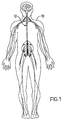
- the partial cross section of the outline of a human body 10 showing the nervous system including the spinal column 12 is depicted in FIG. 1.
- the apparatus of this invention can be used for the introduction of a paddle style lead 55 into the spinal column area 13 of the nervous system.
- Needle assembly 14 is inserted into the spinal column area 13 in a fashion generally known in the art.
- lumen 25 of the needle 15 has an oblong cross section sized to insert a paddle style lead and has a curve at the distal end 35 of the needle 15.
- the needle 15 comprises a body 30 having a proximal end 40 and a distal end 35 and an inside lumen 25.
- the lumen 25 has an oblong cross section.
- the oblong cross section of the lumen 25 is adapted to receive a stylet 45 and a paddle style lead 55.
- the cross section of the lumen 25 is such that the width is greater than the height.
- a typical width for the lumen 25 cavity to receive a paddle style lead 55 is 2.5 mm to 12 mm (0.1" to 0.5") with a height of 1.4 mm to 2.0 mm (0.055" to 0.079").
- the needle 15 is preferably made of stainless steel or other suitable materials.
- the needle 15 may also be adapted to insert multiple wire leads.
- the present invention allows a paddle lead to be inserted percutaneously without requiring the lead to be rolled/contorted to fit the geometry of the needle lumen.
- the needle 15 is further defined by an introducer portion 35 at the body 30 distal end.
- the introducer portion 35 having a top side and a bottom side is shaped to allow for penetration of a patient's skin and other tissue.
- an epidural, Tuohy or modified Tuohy needle may be used.
- the top side of the introducer portion 35 has an orifice 37 to allow the paddle style lead 55 to exit the lumen 25 of the needle 15 within the spinal column area 13 after insertion of the needle 15.
- the preferred embodiment of the needle 15 has an introducer 35 with a curvature.
- the curvature extends from the bottom side of the introducer 35 to the top side of the introducer 35 to facilitate and guide the paddle style lead 55 during insertion.
- the radius of curvature for the introducer 35 is approximately 22.5 mm (0.9"). Those skilled in the art will appreciate that any other curvature may be implanted and still be considered within the scope of the present invention.
- the body 30 proximal end is comprised of a hub 40.
- the hub 40 is affixed to the proximal end of the body 30 and allows the needle 15 to be grasped. Additionally, the hub 40 provides an interface between the needle 15 and the stylet 45 during insertion.
- an alternative embodiment of the hub 40 comprises a Luer lock 105 to allow for extracting or inserting fluids or for allowing the physician to use the loss of resistance method for identifying the epidural space.
- an alternative embodiment of the Luer lock 106 is depicted.
- FIG. 6 it illustrates a perspective view of the stylet 45 having a proximal end that is adapted to mate with the needle hub 40.
- the stylet 45 may be constructed of stainless steel having a length nearly equivalent to the length of the body 30 of the needle 15.
- the stylet 45 has a distal tip 47 shaped for matching with the orifice 37 of the introducer 35 of the needle 15.
- a handle end 48 is affixed to a proximal end of the stylet 45.
- the stylet 45 fills the entire orifice 37 of the introducer 35 to prevent any skin or other tissue from entering the lumen 25 during insertion within the patient.
- FIG. 7 illustrates a top view of a paddle style lead 55 for electrical stimulation.
- the paddle style lead 55 is sized such that the width of the paddle style lead 55 is less than the width of the lumen 25 and such that the height of the paddle style lead 55 is less than the height of the lumen 25.
- the paddle style lead 55 has a lead body 60 and transition area 65. Once inserted in the spinal column area 13, the paddle style lead 55 remains in position and wire leads extend out of the spinal cord typically to a signal generator. The described sizing allows the paddle style lead 55 to be inserted through the lumen 25 into the spinal column area 13 after the needle 15 is inserted in a predetermined position.
- Some paddle style leads require stiffening to facilitate insertion into the spinal cord area.
- the paddle style lead is adapted to accept a stiffening means.
- the stiffening means provides stiffness to the paddle style lead body during implantation and once implanted the paddle style lead becomes relatively flexible.
- the stiffening means is only required with the use of a relatively flexible paddle style lead to facilitate insertion into the spinal column area. Any number of techniques can be used to stiffen the paddle style lead, of which the following are examples.
- FIGS. 8 and 13 illustrate one embodiment of the stiffening means assembly.
- a paddle style lead 70 is adapted on a first side to accept a stiffening member 85 made of formed wire.
- the paddle style lead 70 may be a single or a double lead body.
- a through hole 75 is affixed at a proximal end of the paddle style lead 70 and allows the stiffening member 85 to pass through and continue toward a distal end of the paddle style lead 70.
- the through hole 75 may be constructed of the same material as the paddle style lead 70 or any other suitable material in the form of a strip.
- the preferred embodiment is constructed of the same material as the paddle style lead, typically silicone but polyurethane may be used.
- the strip is shaped to allow the stiffening member 85 to pass into and out of and affix to the paddle style lead 70 on at least two sides.
- a blind hole 80 is affixed at the distal end of the paddle style lead 70 arranged to allow the stiffening member 85 to pass through the through hole 75 and terminate within the blind hole 80.
- the paddle style lead 70 remains relatively stiff while the stiffening member 85 is within the through hole 75 and the blind hole 80.
- the stiffening member 85 is then used to guide the paddle style lead 70 into a predetermined position within the spinal column area 13. After the paddle style lead 70 is in a desired position, the stiffening member 85 is moved in a direction from the distal end to the proximal end of the paddle style lead 70. The stiffening member 85 is not restrained in this direction relative to the movement of the paddle style lead 70. The stiffening member 85 is removeable from the needle 15 while leaving the paddle style lead 70 in the desired position.
- the paddle style lead 70 is relatively flexible after the stiffening member 85 is removed.
- a formed wire is the preferred embodiment for use as the stiffening member 85 for insertion of the paddle style lead 70.
- the stiffening member may also be shaped as a flat strip.
- FIG. 10 depicts yet another embodiment of the stiffening means, a passing elevator 90.
- the passing elevator 90 is constructed of a non-round, elongated length of plastic, typically acetal resin.
- the passing elevator 90 typically has a generally rectangular cross section.
- a handle 92 is attached a curved distal end 95.
- the curved distal end 95 fits within a slot version of the paddle style lead 82 of FIG. 8 as shown in FIG. 9.
- the blind hole 83 and the through hole 84 are shaped to receive the curved distal end 95 of the passing elevator 90.
- the passing elevator 90 is restrained in a direction from the proximal end to the distal end of the paddle style lead 82.
- FIGS. 11 and 12 utilizes a blind hole pocket 98 that extends the length of the pocket paddle style lead 93.
- a stiffener strip 91 with a continuous cross section is inserted within the pocket 98.
- the stiffener strip 91 is long and flat and may have a square or rounded end.
- a continuous ribbon lead 100 for use with the improved needle for percutaneous insertion is depicted.
- the continuous ribbon lead 100 may be constructed of silicone that runs the entire length of the lead.
- the continuous ribbon lead 100 has a continuous cross section with no transition area.
- the continuous ribbon lead 100 is inserted through the needle 15 of FIG. 2, and the continuous ribbon lead 100 exits the spinal cord to typically a signal generator.
- the continuous ribbon lead 100 may also be adapted with the stiffening means shown in FIGS. 8, 9 and 11.
- the description of the apparatus of this invention is not intended to be limiting but is merely illustrative of the preferred embodiment of this invention.
- Those of ordinary skill in the art will recognize that modifications can be made to the needle and paddle style leads described herein.
- the strip of the through hole 75 and blind hole 80 on the paddle style lead 70 may be of alternative shapes to allow for various shaped stiffening members 85.
Abstract
Description
- This invention relates generally to an apparatus for the percutaneous introduction of a paddle style lead into the space near the spinal cord of a patient. Moreover, this invention relates particularly, but not exclusively, to the percutaneous introduction of the paddle style lead into the spinal column area through a needle with an oblong cross section.
- Spinal cord stimulation is used to treat a multitude of disorders including multiple sclerosis, spinal cord injury, cerebral palsy, amyotrophic lateral sclerosis, dystonia, torticollis and other neurological disorders. Spinal cord stimulation is also useful for treating pain including intractable malignant and nonmalignant pain. Neural stimulation electrodes and leads implanted in the epidural space of the spinal cord of a patient stimulate selected locations of the spinal cord for treatment of pain and various conditions.
- Surgically implantable paddle style leads, or flat leads, and percutaneous insertable wire leads for the spinal cord have been in use for some time. These paddle style, or flat leads, and wire leads are used for electrical stimulation of neurons in the spinal cord. Two types of leads are generally used for spinal cord stimulation: 1) wire and 2) paddle.
- Typically, a wire lead is introduced into the spinal column using a needle and a stylet assembly. The needle and stylet are inserted into the spinal column area between adjacent vertebrae until the tip of the needle and stylet are advanced into the epidural space of the spinal column area. The stylet is withdrawn and a wire lead is inserted through the open area or lumen of the needle and into the epidural space to a selected location adjacent to the spinal cord. Some needle and stylet assemblies have a curved distal tip to facilitate introduction of the lead at an angle to the axis of the lumen portion of the needle. The needle typically has a side opening or orifice at its distal end for insertion of the lead into the selected location of the spinal cord. In some assemblies, the stylet may fill the entire lumen cavity including the side opening of the needle to prevent the collection of tissue in the lumen cavity during insertion of the needle. The stylet can also provide rigidity to the needle body for use during insertion.
- Current needle technology requires that all leads be of a circular cross section in order to be placed through the lumen portion of the needle into the epidural space. Needles used for insertion of the wire leads typically have a circular cross section between 14 and 18 gauge.
- The paddle style or flat leads are generally rectangular shaped flat paddles that must be surgically implanted. To introduce a paddle style lead into the epidural space percutaneously using needle insertion, the paddle lead must be rolled to a circular shape to slide through the typical circular cross section needle. The method of rolling the paddle lead and inserting through a needle and unrolling the paddle style lead has not been perfected for use. The only way to insert a paddle style lead is by a surgical procedure known as a laminotomy, a laminectomy, or similar surgical procedure. Because the paddle style lead must be surgically implanted, anesthesiologists may not perform the procedure.
- Accordingly, there remains a need in the art for a non-surgical method of inserting a paddle style or flat lead into the spinal cord area.
- The present invention recognizes and provides a solution to the problems associated with the percutaneous introduction of paddle style leads. The invention provides a unique needle for percutaneous insertion of a paddle style lead into the spinal column area and, in particular provides
- a needle assembly for introduction of a paddle style lead near a spinal column of a patient, comprising:
- a body having a proximal end and a distal end, and a lumen having a continuous oblong cross section, the distal end having an introducer portion; the introducer portion having an orifice to allow for protrusion of the paddle style lead from the lumen; and
- a hub affixed to the proximal end of the body adapted to receive a stylet;
- a stylet having a handle end at a proximal end and adapted to be insertable within the lumen; and
- a paddle style lead having a lead body and wires connected at a transition area adapted to be inserted through the oblong cross section of the lumen, the lead body adaptable to accept a stiffening member. Additionally, the invention preferably includes means for stiffening the paddle style lead to facilitate insertion of the lead in the spinal column area.
-
- Accordingly, an object of the present invention is to provide a non-surgical apparatus for percutaneous insertion of paddle style leads that may be utilized by both surgeons and anesthesiologists. Current needles used for introduction of leads for electrical stimulation have a round cross section. Paddle style leads cannot be inserted through these needles. The paddle style lead must be inserted by a surgeon performing a laminotomy, a laminectomy or similar surgical procedure where the surgeon cuts open the tissue and then slides the lead into the proper position. This novel invention uses a needle having a lumen with an oblong cross section. A flat, paddle style lead based on current lead technology is passed through the oblong cross section of the lumen in this needle for introduction into the spinal column area. This invention allows for percutaneous insertion through a needle without performing the above mentioned surgical procedures.
- Another object of this invention is to enable a less traumatic procedure for patients during the implantation of paddle style leads for treatment. Surgical introduction of leads for electrical stimulation is traumatic for patients. Insertion of leads for electrical stimulation utilizing an oblong needle that is inserted near the spinal column is less traumatic for patients than surgery where the surgeon must cut the tissue open and then slide the lead into the proper position.
- Yet another object of this invention is to provide an apparatus for a paddle style lead with a stiffening member to facilitate insertion through the oblong cross section of the lumen of the needle. A stiffening stylet can be used to stiffen the paddle style lead. Another alternative is to use a continuous ribbon style lead such that the cross section of the lead body is the same as the cross section of the paddle. This procedure and apparatus is not limited to use with any specific paddle style or flat lead and can be used for introduction of leads into other areas.
- A further object of this invention is to provide a paddle style lead that remains relatively stiff during implantation and positioning and becomes relatively flaccid once inserted. Lead paddles that are stiff during implantation and flaccid while implanted can be a substantial benefit during the introduction of longer lead paddles and as an improvement to current insertion procedures. A stylet, or any other suitable, temporary stiffening method, that may be reversed after implant, will aid the physician in steering the paddle to the desired location and avoid buckling should the physician need to advance the paddle lead from one spinal segment to the next.
- Yet another embodiment of this invention is to provide for stiffening the paddle style lead using temperature controlled materials. The lead is composed of at least one temperature controlled material and the temperature controlled material remains relatively stiff when at temperatures below a persons body temperature and the same lead becomes relatively flaccid after heating to at least body temperature after insertion. A relatively stiff paddle improves insertability while a flaccid lead is desired once inserted.
- The full range of objects, advantages, and features of the invention are only appreciated by a full reading of this specification and a full understanding of the invention. Therefore, to complete this specification, a detailed description of the invention and the preferred embodiments follow, (by way of example only), after a brief description of the drawings wherein additional objects, advantages and features of the invention are disclosed.
- A preferred embodiment of the invention is illustrated in the drawings, wherein like reference numerals refer to like elements in the various views, and wherein:
- Figure 1 is a perspective representation in partial cross section of the human body nervous system.
- Figure 2 is a perspective representation in partial cross section of the introduction of the assembled needle within the spinal area.
- Figure 3 is a perspective view of the preferred needle of the present invention.
- Figure 4 is a perspective view of the preferred curved tip of the introducer portion of the needle of the present invention.
- Figure 5 is a perspective view of the preferred hub of the needle of the present invention.
- Figure 6 is a perspective view of the preferred stylet of the present invention.
- Figure 7 is a top view of a paddle style lead.
- Figure 8 is a perspective view of an improved paddle lead adaptable to receive a stiffening member during insertion.
- Figure 9 is a perspective view of an improved paddle lead adaptable to receive a stiffener strip.
- Figure 10 is a perspective view of a passing elevator stiffening member.
- Figure 11 is a perspective view of a pocket lead with stiffener strip.
- Figure 12 is a cross section view of the pocket lead.
- Figure 13 is a perspective view of a stiffening member.
- Figure 14 is a perspective view of a continuous ribbon style paddle lead.
- Figure 15 is a partial cross section perspective view of a Luer lock.
- Figure 16 is a perspective view of an alternative Luer lock.
-
- In the drawings, FIGS. 3-6 illustrate a preferred embodiment of a
needle 15 andstylet 45 for use in the procedure for introducing apaddle style lead 55 within thespinal column area 13 as depicted in FIG. 2. The partial cross section of the outline of ahuman body 10 showing the nervous system including thespinal column 12 is depicted in FIG. 1. The apparatus of this invention can be used for the introduction of apaddle style lead 55 into thespinal column area 13 of the nervous system. - Referring to Figure 2, the assembled needle and
stylet 14 are further depicted in relation to thespinal area 13.Needle assembly 14 is inserted into thespinal column area 13 in a fashion generally known in the art. In accordance with the novel improvement of the present invention,lumen 25 of theneedle 15 has an oblong cross section sized to insert a paddle style lead and has a curve at thedistal end 35 of theneedle 15. - Turning now to FIG. 3, a preferred embodiment of the
needle 15 for percutaneous implant of a paddle style lead is depicted in perspective view. Theneedle 15 comprises abody 30 having aproximal end 40 and adistal end 35 and aninside lumen 25. Thelumen 25 has an oblong cross section. The oblong cross section of thelumen 25 is adapted to receive astylet 45 and apaddle style lead 55. The cross section of thelumen 25 is such that the width is greater than the height. A typical width for thelumen 25 cavity to receive apaddle style lead 55 is 2.5 mm to 12 mm (0.1" to 0.5") with a height of 1.4 mm to 2.0 mm (0.055" to 0.079"). Theneedle 15 is preferably made of stainless steel or other suitable materials. Theneedle 15 may also be adapted to insert multiple wire leads. Advantageously, the present invention allows a paddle lead to be inserted percutaneously without requiring the lead to be rolled/contorted to fit the geometry of the needle lumen. - The
needle 15 is further defined by anintroducer portion 35 at thebody 30 distal end. Referring to FIG. 4, theintroducer portion 35 having a top side and a bottom side is shaped to allow for penetration of a patient's skin and other tissue. Typically, an epidural, Tuohy or modified Tuohy needle may be used. The top side of theintroducer portion 35 has anorifice 37 to allow thepaddle style lead 55 to exit thelumen 25 of theneedle 15 within thespinal column area 13 after insertion of theneedle 15. The preferred embodiment of theneedle 15 has anintroducer 35 with a curvature. The curvature extends from the bottom side of theintroducer 35 to the top side of theintroducer 35 to facilitate and guide thepaddle style lead 55 during insertion. As preferred, the radius of curvature for theintroducer 35 is approximately 22.5 mm (0.9"). Those skilled in the art will appreciate that any other curvature may be implanted and still be considered within the scope of the present invention. - Referring to FIG. 5, the
body 30 proximal end is comprised of ahub 40. Thehub 40 is affixed to the proximal end of thebody 30 and allows theneedle 15 to be grasped. Additionally, thehub 40 provides an interface between theneedle 15 and thestylet 45 during insertion. Referring to FIG. 15, an alternative embodiment of thehub 40 comprises aLuer lock 105 to allow for extracting or inserting fluids or for allowing the physician to use the loss of resistance method for identifying the epidural space. Referring to FIG. 16, an alternative embodiment of theLuer lock 106 is depicted. - Turning to now to FIG. 6, it illustrates a perspective view of the
stylet 45 having a proximal end that is adapted to mate with theneedle hub 40. Thestylet 45 may be constructed of stainless steel having a length nearly equivalent to the length of thebody 30 of theneedle 15. Thestylet 45 has adistal tip 47 shaped for matching with theorifice 37 of theintroducer 35 of theneedle 15. Ahandle end 48 is affixed to a proximal end of thestylet 45. In the preferred embodiment, thestylet 45 fills theentire orifice 37 of theintroducer 35 to prevent any skin or other tissue from entering thelumen 25 during insertion within the patient. - FIG. 7 illustrates a top view of a
paddle style lead 55 for electrical stimulation. Thepaddle style lead 55 is sized such that the width of thepaddle style lead 55 is less than the width of thelumen 25 and such that the height of thepaddle style lead 55 is less than the height of thelumen 25. Thepaddle style lead 55 has alead body 60 andtransition area 65. Once inserted in thespinal column area 13, thepaddle style lead 55 remains in position and wire leads extend out of the spinal cord typically to a signal generator. The described sizing allows thepaddle style lead 55 to be inserted through thelumen 25 into thespinal column area 13 after theneedle 15 is inserted in a predetermined position. - Some paddle style leads require stiffening to facilitate insertion into the spinal cord area. The paddle style lead is adapted to accept a stiffening means. The stiffening means provides stiffness to the paddle style lead body during implantation and once implanted the paddle style lead becomes relatively flexible. The stiffening means is only required with the use of a relatively flexible paddle style lead to facilitate insertion into the spinal column area. Any number of techniques can be used to stiffen the paddle style lead, of which the following are examples.
- FIGS. 8 and 13 illustrate one embodiment of the stiffening means assembly. A
paddle style lead 70 is adapted on a first side to accept a stiffening member 85 made of formed wire. Thepaddle style lead 70 may be a single or a double lead body. A throughhole 75 is affixed at a proximal end of thepaddle style lead 70 and allows the stiffening member 85 to pass through and continue toward a distal end of thepaddle style lead 70. The throughhole 75 may be constructed of the same material as thepaddle style lead 70 or any other suitable material in the form of a strip. The preferred embodiment is constructed of the same material as the paddle style lead, typically silicone but polyurethane may be used. The strip is shaped to allow the stiffening member 85 to pass into and out of and affix to thepaddle style lead 70 on at least two sides. Ablind hole 80 is affixed at the distal end of thepaddle style lead 70 arranged to allow the stiffening member 85 to pass through the throughhole 75 and terminate within theblind hole 80. When fully inserted into theblind hole 80, any further movement of the stiffening member 85 in a direction from the proximal end to the distal end of thepaddle style lead 70 pushes thepaddle style lead 70 with the stiffening member 85. Once the stiffening member 85 terminates at theblind hole 80, the stiffening member 85 pushes against theblind hole 80 to guide thepaddle style lead 70 into a desired position within thespinal column area 13. Thepaddle style lead 70 remains relatively stiff while the stiffening member 85 is within the throughhole 75 and theblind hole 80. The stiffening member 85 is then used to guide thepaddle style lead 70 into a predetermined position within thespinal column area 13. After thepaddle style lead 70 is in a desired position, the stiffening member 85 is moved in a direction from the distal end to the proximal end of thepaddle style lead 70. The stiffening member 85 is not restrained in this direction relative to the movement of thepaddle style lead 70. The stiffening member 85 is removeable from theneedle 15 while leaving thepaddle style lead 70 in the desired position. Thepaddle style lead 70 is relatively flexible after the stiffening member 85 is removed. A formed wire is the preferred embodiment for use as the stiffening member 85 for insertion of thepaddle style lead 70. The stiffening member may also be shaped as a flat strip. - FIG. 10 depicts yet another embodiment of the stiffening means, a passing
elevator 90. The passingelevator 90 is constructed of a non-round, elongated length of plastic, typically acetal resin. The passingelevator 90 typically has a generally rectangular cross section. Ahandle 92 is attached a curveddistal end 95. The curveddistal end 95 fits within a slot version of thepaddle style lead 82 of FIG. 8 as shown in FIG. 9. Theblind hole 83 and the throughhole 84 are shaped to receive the curveddistal end 95 of the passingelevator 90. The passingelevator 90 is restrained in a direction from the proximal end to the distal end of thepaddle style lead 82. Once the passingelevator 90 is fully inserted in the slotblind hole 83 of thepaddle style lead 82, thepaddle style lead 82 moves in conjunction with the passingelevator 90 and allows thepaddle style lead 82 to be pulled into a desired position. The passingelevator 90 is not restrained in the opposite direction, allowing the passingelevator 90 to be removed from the patient's body while leaving thepaddle style lead 82 in the desired position. An alternative embodiment for stiffening means shown in FIGS. 11 and 12 utilizes ablind hole pocket 98 that extends the length of the pocketpaddle style lead 93. Astiffener strip 91 with a continuous cross section is inserted within thepocket 98. Thestiffener strip 91 is long and flat and may have a square or rounded end. - Referring to FIG. 14, a
continuous ribbon lead 100 for use with the improved needle for percutaneous insertion is depicted. Thecontinuous ribbon lead 100 may be constructed of silicone that runs the entire length of the lead. Thecontinuous ribbon lead 100 has a continuous cross section with no transition area. Thecontinuous ribbon lead 100 is inserted through theneedle 15 of FIG. 2, and thecontinuous ribbon lead 100 exits the spinal cord to typically a signal generator. Thecontinuous ribbon lead 100 may also be adapted with the stiffening means shown in FIGS. 8, 9 and 11. - The description of the apparatus of this invention is not intended to be limiting but is merely illustrative of the preferred embodiment of this invention. Those of ordinary skill in the art will recognize that modifications can be made to the needle and paddle style leads described herein. For example, the strip of the through
hole 75 andblind hole 80 on thepaddle style lead 70 may be of alternative shapes to allow for various shaped stiffening members 85.
Claims (20)
- A needle assembly for introduction of a paddle style lead near a spinal column of a patient, comprising:a body having a proximal end and a distal end, and a lumen having a continuous oblong cross section, the distal end having an introducer portion; the introducer portion having an orifice to allow for protrusion of the paddle style lead from the lumen; anda hub affixed to the proximal end of the body adapted to receive a stylet;a stylet having a handle end at a proximal end and adapted to be insertable within the lumen; anda paddle style lead having a lead body and wires connected at a transition area adapted to be inserted through the oblong cross section of the lumen, the lead body adaptable to accept a stiffening member.
- The needle assembly of claim 1, wherein the lead body has a first side and a second side, the first side having a blind hole at a distal end adapted to receive a stiffening member from the proximal end terminating at the blind hole.
- The needle assembly of claim 1, wherein the lead body has a first side and a second side, the first side having a blind hole at a distal end and a through hole at a proximal end, the blind hole adapted to receive a stiffening member through the through hole terminating at the blind hole.
- The needle assembly of claim 1, wherein the lead body has an acceptor means affixed to the lead body to allow a stiffening means to mate with the lead body.
- The needle assembly of claim 1, wherein the lead body has a continuous cross section extending from the lead body to a position outside a patient's body after implantation or to the implanted extension.
- The needle assembly of claim 1, wherein the lead body is made of at least one temperature controlled material, the at least one temperature controlled material being relatively stiff at a first temperature below a body temperature and relatively flexible at a second temperature at least at the body temperature.
- The needle assembly of claim 1, wherein the lead body has a first side and a second side, the first side having a pocket substantially the entire length of the paddle style lead adapted to receive a stiffening member.
- The needle assembly of claim 1, wherein the stiffening member is a passing elevator.
- The needle assembly of claim 2, wherein the stiffening member is a passing elevator.
- The needle assembly of claim 7, wherein the stiffening member is a passing elevator.
- The needle of claim 3, wherein the stiffening member is a formed wire.
- The needle of claim 3, wherein the stiffening member is a flat strip.
- The needle of claim 7, wherein the stiffening member is a flat strip.
- The needle assembly of claim 1, wherein the introducer has a curvature extending from the bottom side toward the top side at the distal end to provide a guide for introduction of the paddle style lead near the spinal column.
- The needle assembly of claim 1, wherein the hub is a Luer lock.
- A paddle style lead, comprising, in combination:a paddle lead having a first side and a second side, the first side having a blind hole at a distal end and a through hole at a proximal end adapted to receive a stiffening member;a stiffening member received through the through hole and terminating at the blind hole.
- The paddle style lead of claim 16, wherein the stiffening member is a formed wire.
- The paddle style lead of claim 16, wherein the stiffening member is a passing elevator.
- The paddle style lead of claim 16, wherein the stiffening member is a flat strip.
- A paddle style lead, comprising a paddle lead made of at least one temperature controlled material, the at least one temperature controlled material being relatively stiff at a first temperature below a body temperature and relatively flexible at a second temperature at least at the body temperature.
Applications Claiming Priority (2)
| Application Number | Priority Date | Filing Date | Title |
|---|---|---|---|
| US09/303,045 US6249707B1 (en) | 1999-04-30 | 1999-04-30 | Apparatus and method for percutaneous implant of a paddle style lead |
| US303045 | 1999-04-30 |
Publications (3)
| Publication Number | Publication Date |
|---|---|
| EP1048271A2 true EP1048271A2 (en) | 2000-11-02 |
| EP1048271A3 EP1048271A3 (en) | 2000-12-13 |
| EP1048271B1 EP1048271B1 (en) | 2006-11-29 |
Family
ID=23170309
Family Applications (1)
| Application Number | Title | Priority Date | Filing Date |
|---|---|---|---|
| EP00109071A Expired - Lifetime EP1048271B1 (en) | 1999-04-30 | 2000-05-02 | Apparatus and method for percutaneous implant of a paddle style lead |
Country Status (3)
| Country | Link |
|---|---|
| US (1) | US6249707B1 (en) |
| EP (1) | EP1048271B1 (en) |
| DE (1) | DE60032052T2 (en) |
Cited By (19)
| Publication number | Priority date | Publication date | Assignee | Title |
|---|---|---|---|---|
| WO2003013650A1 (en) | 2001-08-10 | 2003-02-20 | Advanced Neuromodulation Systems, Inc. | Stimulation/sensing lead adapted for percutaneous insertion |
| US6658302B1 (en) * | 1998-02-10 | 2003-12-02 | Advanced Bionics Corporation | Insertion needle for use with implantable, expandable, multicontact electrodes |
| WO2005032650A1 (en) * | 2003-10-03 | 2005-04-14 | Medtronic, Inc. | Kit for implantation of therapy elements |
| US7437197B2 (en) | 2003-10-23 | 2008-10-14 | Medtronic, Inc. | Medical lead and manufacturing method therefor |
| EP2004280A2 (en) * | 2006-03-16 | 2008-12-24 | John M. Swoyer | High efficiency neurostimulation lead |
| US7499755B2 (en) | 2002-10-23 | 2009-03-03 | Medtronic, Inc. | Paddle-style medical lead and method |
| US7763034B2 (en) | 2006-01-24 | 2010-07-27 | Medtronic, Inc. | Transobturator lead implantation for pelvic floor stimulation |
| US7792591B2 (en) | 2005-06-09 | 2010-09-07 | Medtronic, Inc. | Introducer for therapy delivery elements |
| US7797057B2 (en) | 2002-10-23 | 2010-09-14 | Medtronic, Inc. | Medical paddle lead and method for spinal cord stimulation |
| US8340779B2 (en) | 2003-08-29 | 2012-12-25 | Medtronic, Inc. | Percutaneous flat lead introducer |
| US8954162B2 (en) | 2007-04-25 | 2015-02-10 | Medtronic, Inc. | Medical device implantation |
| US9192409B2 (en) | 2008-01-23 | 2015-11-24 | Boston Scientific Neuromodulation Corporation | Steerable stylet handle assembly |
| US9393416B2 (en) | 2005-06-09 | 2016-07-19 | Medtronic, Inc. | Peripheral nerve field stimulation and spinal cord stimulation |
| US9399130B2 (en) | 2007-04-25 | 2016-07-26 | Medtronic, Inc. | Cannula configured to deliver test stimulation |
| US9492655B2 (en) | 2008-04-25 | 2016-11-15 | Boston Scientific Neuromodulation Corporation | Stimulation system with percutaneously deliverable paddle lead and methods of making and using |
| US9561053B2 (en) | 2007-04-25 | 2017-02-07 | Medtronic, Inc. | Implant tool to facilitate medical device implantation |
| US10300273B2 (en) | 2005-06-09 | 2019-05-28 | Medtronic, Inc. | Combination therapy including peripheral nerve field stimulation |
| US10328271B2 (en) | 2015-11-12 | 2019-06-25 | Medtronic, Inc. | Implantable electrical stimulator with deflecting tip lead |
| US11547424B2 (en) | 2018-03-21 | 2023-01-10 | Joimax Gmbh | Instrument set for spinal operations |
Families Citing this family (64)
| Publication number | Priority date | Publication date | Assignee | Title |
|---|---|---|---|---|
| US6309401B1 (en) * | 1999-04-30 | 2001-10-30 | Vladimir Redko | Apparatus and method for percutaneous implant of a paddle style lead |
| US20020035379A1 (en) * | 2000-09-18 | 2002-03-21 | Bardy Gust H. | Subcutaneous electrode for transthoracic conduction with improved installation characteristics |
| US6754528B2 (en) | 2001-11-21 | 2004-06-22 | Cameraon Health, Inc. | Apparatus and method of arrhythmia detection in a subcutaneous implantable cardioverter/defibrillator |
| US20020035381A1 (en) * | 2000-09-18 | 2002-03-21 | Cameron Health, Inc. | Subcutaneous electrode with improved contact shape for transthoracic conduction |
| US7069080B2 (en) | 2000-09-18 | 2006-06-27 | Cameron Health, Inc. | Active housing and subcutaneous electrode cardioversion/defibrillating system |
| US7146212B2 (en) | 2000-09-18 | 2006-12-05 | Cameron Health, Inc. | Anti-bradycardia pacing for a subcutaneous implantable cardioverter-defibrillator |
| US6721597B1 (en) | 2000-09-18 | 2004-04-13 | Cameron Health, Inc. | Subcutaneous only implantable cardioverter defibrillator and optional pacer |
| US20020035377A1 (en) * | 2000-09-18 | 2002-03-21 | Cameron Health, Inc. | Subcutaneous electrode for transthoracic conduction with insertion tool |
| US8060211B2 (en) * | 2001-02-13 | 2011-11-15 | Second Sight Medical Products, Inc. | Method of reducing retinal stress caused by an implantable retinal electrode array |
| DE60207216T2 (en) * | 2001-03-08 | 2006-07-06 | Medtronic, Inc., Minneapolis | CABLE WITH ANGLE AND SPACE POSITION ADJUSTABLE BETWEEN ELECTRODES |
| US7072719B2 (en) * | 2001-09-20 | 2006-07-04 | Medtronic, Inc. | Implantable percutaneous stimulation lead with interlocking elements |
| US7697995B2 (en) * | 2002-04-25 | 2010-04-13 | Medtronic, Inc. | Surgical lead paddle |
| US20050033393A1 (en) * | 2003-08-08 | 2005-02-10 | Advanced Neuromodulation Systems, Inc. | Apparatus and method for implanting an electrical stimulation system and a paddle style electrical stimulation lead |
| US7359755B2 (en) * | 2003-08-08 | 2008-04-15 | Advanced Neuromodulation Systems, Inc. | Method and apparatus for implanting an electrical stimulation lead using a flexible introducer |
| US20050288758A1 (en) * | 2003-08-08 | 2005-12-29 | Jones Timothy S | Methods and apparatuses for implanting and removing an electrical stimulation lead |
| US20050049663A1 (en) * | 2003-08-29 | 2005-03-03 | Harris Charmaine K. | Percutaneous flat lead introducer |
| US20050075707A1 (en) * | 2003-09-16 | 2005-04-07 | Meadows Paul M. | Axial to planar lead conversion device and method |
| US8060207B2 (en) | 2003-12-22 | 2011-11-15 | Boston Scientific Scimed, Inc. | Method of intravascularly delivering stimulation leads into direct contact with tissue |
| US20050137646A1 (en) * | 2003-12-22 | 2005-06-23 | Scimed Life Systems, Inc. | Method of intravascularly delivering stimulation leads into brain |
| US7295875B2 (en) * | 2004-02-20 | 2007-11-13 | Boston Scientific Scimed, Inc. | Method of stimulating/sensing brain with combination of intravascularly and non-vascularly delivered leads |
| US7590454B2 (en) | 2004-03-12 | 2009-09-15 | Boston Scientific Neuromodulation Corporation | Modular stimulation lead network |
| US20050203600A1 (en) * | 2004-03-12 | 2005-09-15 | Scimed Life Systems, Inc. | Collapsible/expandable tubular electrode leads |
| US7177702B2 (en) * | 2004-03-12 | 2007-02-13 | Scimed Life Systems, Inc. | Collapsible/expandable electrode leads |
| US8224459B1 (en) | 2004-04-30 | 2012-07-17 | Boston Scientific Neuromodulation Corporation | Insertion tool for paddle-style electrode |
| US8706259B2 (en) * | 2004-04-30 | 2014-04-22 | Boston Scientific Neuromodulation Corporation | Insertion tool for paddle-style electrode |
| US8412348B2 (en) | 2004-05-06 | 2013-04-02 | Boston Scientific Neuromodulation Corporation | Intravascular self-anchoring integrated tubular electrode body |
| US7286879B2 (en) | 2004-07-16 | 2007-10-23 | Boston Scientific Scimed, Inc. | Method of stimulating fastigium nucleus to treat neurological disorders |
| US7937160B2 (en) * | 2004-12-10 | 2011-05-03 | Boston Scientific Neuromodulation Corporation | Methods for delivering cortical electrode leads into patient's head |
| EP1904154B1 (en) * | 2005-06-09 | 2011-01-26 | Medtronic, Inc. | Implantable medical lead |
| WO2006133444A2 (en) * | 2005-06-09 | 2006-12-14 | Medtronic, Inc. | Implantable medical device with electrodes on multiple housing surfaces |
| US8244379B2 (en) | 2006-04-26 | 2012-08-14 | Medtronic, Inc. | Pericardium fixation concepts of epicardium pacing leads and tools |
| US9339643B1 (en) * | 2007-03-30 | 2016-05-17 | Boston Scientific Neuromodulation Corporation | Acutely stiff implantable electrodes |
| US9008782B2 (en) * | 2007-10-26 | 2015-04-14 | Medtronic, Inc. | Occipital nerve stimulation |
| IL194805A0 (en) * | 2007-10-29 | 2009-08-03 | Lifescan Inc | Medical device flexible conduit and method of manufacture |
| CA2641701C (en) * | 2007-10-30 | 2015-12-08 | Lifescan, Inc. | Integrated conduit insertion medical device |
| US8147465B2 (en) * | 2008-02-26 | 2012-04-03 | Medtronic, Inc. | Delivery needle apparatus with sleeve |
| US20110071540A1 (en) * | 2008-06-03 | 2011-03-24 | Medtronic, Inc | Lead with distal engagement feature to facilitate lead placement |
| WO2009148938A1 (en) * | 2008-06-03 | 2009-12-10 | Medtronic, Inc. | Lead with distal engagement element to facilitate lead placement |
| US20100030227A1 (en) * | 2008-07-31 | 2010-02-04 | Medtronic, Inc. | Medical lead implantation |
| US9486628B2 (en) | 2009-03-31 | 2016-11-08 | Inspire Medical Systems, Inc. | Percutaneous access for systems and methods of treating sleep apnea |
| US11045221B2 (en) * | 2009-10-30 | 2021-06-29 | Medtronic, Inc. | Steerable percutaneous paddle stimulation lead |
| US8588936B2 (en) | 2010-07-28 | 2013-11-19 | University Of Utah Research Foundation | Spinal cord stimulation system and methods of using same |
| WO2012112428A1 (en) * | 2011-02-16 | 2012-08-23 | Boston Scientific Neuromodulation Corporation | Systems and methods for implanting paddle lead assemblies of electrical stimulation systems |
| US8543223B2 (en) | 2011-03-11 | 2013-09-24 | Greatbach Ltd. | Implantable lead with braided conductors |
| WO2012141960A1 (en) * | 2011-04-11 | 2012-10-18 | Boston Scientific Neuromodulation Corporation | Systems and methods for enhancing paddle lead placement |
| WO2013154757A1 (en) * | 2012-04-10 | 2013-10-17 | NeuroAccess Technologies | Electrical lead with coupling features |
| WO2013154756A1 (en) * | 2012-04-10 | 2013-10-17 | NeuroAccess Technologies | Electrical lead placement system |
| US9308022B2 (en) | 2012-12-10 | 2016-04-12 | Nevro Corporation | Lead insertion devices and associated systems and methods |
| US9872997B2 (en) | 2013-03-15 | 2018-01-23 | Globus Medical, Inc. | Spinal cord stimulator system |
| US9878170B2 (en) | 2013-03-15 | 2018-01-30 | Globus Medical, Inc. | Spinal cord stimulator system |
| US9265524B2 (en) | 2013-03-15 | 2016-02-23 | The Cleveland Clinic Foundation | Devices and methods for tissue graft delivery |
| US10413730B2 (en) | 2013-03-15 | 2019-09-17 | Cirtec Medical Corp. | Implantable pulse generator that generates spinal cord stimulation signals for a human body |
| US10080896B2 (en) | 2013-03-15 | 2018-09-25 | Cirtec Medical Corp. | Implantable pulse generator that generates spinal cord stimulation signals for a human body |
| US10016604B2 (en) | 2013-03-15 | 2018-07-10 | Globus Medical, Inc. | Implantable pulse generator that generates spinal cord stimulation signals for a human body |
| US9440076B2 (en) | 2013-03-15 | 2016-09-13 | Globus Medical, Inc. | Spinal cord stimulator system |
| US10226628B2 (en) | 2013-03-15 | 2019-03-12 | Cirtec Medical Corp. | Implantable pulse generator that generates spinal cord stimulation signals for a human body |
| US9887574B2 (en) | 2013-03-15 | 2018-02-06 | Globus Medical, Inc. | Spinal cord stimulator system |
| US9867981B2 (en) | 2013-12-04 | 2018-01-16 | Boston Scientific Neuromodulation Corporation | Insertion tool for implanting a paddle lead and methods and systems utilizing the tool |
| US9643003B2 (en) | 2014-11-10 | 2017-05-09 | Steven Sounyoung Yu | Craniofacial neurostimulation for treatment of pain conditions |
| WO2016114923A1 (en) | 2015-01-13 | 2016-07-21 | Boston Scientific Neuromodulation Corporation | Insertion tool for implanting a paddle lead and methods and systems utilizing the tool |
| US11179562B1 (en) * | 2015-06-18 | 2021-11-23 | Jan ECKERMANN | Spinal cord stimulator paddle applicator, neurostimulation lead, and steering mechanism |
| US20160367797A1 (en) * | 2015-06-18 | 2016-12-22 | Jan ECKERMANN | Spinal cord stimulator paddle applicator, neurostimulation lead, and steering mechanism |
| WO2018222698A1 (en) * | 2017-05-30 | 2018-12-06 | Ramadi Khalil | Method and apparatus for precise measurement and dispensing of liquids |
| USD933214S1 (en) | 2020-04-08 | 2021-10-12 | Paul Charles Garell | Passing elevator |
Citations (10)
| Publication number | Priority date | Publication date | Assignee | Title |
|---|---|---|---|---|
| US4141365A (en) * | 1977-02-24 | 1979-02-27 | The Johns Hopkins University | Epidural lead electrode and insertion needle |
| US4285347A (en) * | 1979-07-25 | 1981-08-25 | Cordis Corporation | Stabilized directional neural electrode lead |
| US4379462A (en) * | 1980-10-29 | 1983-04-12 | Neuromed, Inc. | Multi-electrode catheter assembly for spinal cord stimulation |
| US4519403A (en) * | 1983-04-29 | 1985-05-28 | Medtronic, Inc. | Balloon lead and inflator |
| US4588398A (en) * | 1984-09-12 | 1986-05-13 | Warner-Lambert Company | Catheter tip configuration |
| US5255691A (en) * | 1991-11-13 | 1993-10-26 | Medtronic, Inc. | Percutaneous epidural lead introducing system and method |
| WO1997028844A1 (en) * | 1996-02-08 | 1997-08-14 | Heartport, Inc. | Thoracoscopic defibrillation system and method |
| US5669882A (en) * | 1996-04-23 | 1997-09-23 | Pyles; Stephen | Curved epidural needle system |
| WO1997037720A1 (en) * | 1996-04-04 | 1997-10-16 | Medtronic, Inc. | Living tissue stimulation and recording techniques |
| WO2000009177A1 (en) * | 1998-08-17 | 2000-02-24 | Edwards Lifesciences Corporation | Medical devices having improved antimicrobial/antithrombogenic properties |
Family Cites Families (4)
| Publication number | Priority date | Publication date | Assignee | Title |
|---|---|---|---|---|
| US4270549A (en) * | 1979-04-30 | 1981-06-02 | Mieczyslaw Mirowski | Method for implanting cardiac electrodes |
| US5762629A (en) | 1991-10-30 | 1998-06-09 | Smith & Nephew, Inc. | Oval cannula assembly and method of use |
| FR2688407A1 (en) | 1992-03-12 | 1993-09-17 | Sallerin Thierry | Needle for percutaneous puncture of double-chamber venous arteries (trunks) |
| US5464447A (en) * | 1994-01-28 | 1995-11-07 | Sony Corporation | Implantable defibrillator electrodes |
-
1999
- 1999-04-30 US US09/303,045 patent/US6249707B1/en not_active Expired - Fee Related
-
2000
- 2000-05-02 DE DE60032052T patent/DE60032052T2/en not_active Expired - Lifetime
- 2000-05-02 EP EP00109071A patent/EP1048271B1/en not_active Expired - Lifetime
Patent Citations (10)
| Publication number | Priority date | Publication date | Assignee | Title |
|---|---|---|---|---|
| US4141365A (en) * | 1977-02-24 | 1979-02-27 | The Johns Hopkins University | Epidural lead electrode and insertion needle |
| US4285347A (en) * | 1979-07-25 | 1981-08-25 | Cordis Corporation | Stabilized directional neural electrode lead |
| US4379462A (en) * | 1980-10-29 | 1983-04-12 | Neuromed, Inc. | Multi-electrode catheter assembly for spinal cord stimulation |
| US4519403A (en) * | 1983-04-29 | 1985-05-28 | Medtronic, Inc. | Balloon lead and inflator |
| US4588398A (en) * | 1984-09-12 | 1986-05-13 | Warner-Lambert Company | Catheter tip configuration |
| US5255691A (en) * | 1991-11-13 | 1993-10-26 | Medtronic, Inc. | Percutaneous epidural lead introducing system and method |
| WO1997028844A1 (en) * | 1996-02-08 | 1997-08-14 | Heartport, Inc. | Thoracoscopic defibrillation system and method |
| WO1997037720A1 (en) * | 1996-04-04 | 1997-10-16 | Medtronic, Inc. | Living tissue stimulation and recording techniques |
| US5669882A (en) * | 1996-04-23 | 1997-09-23 | Pyles; Stephen | Curved epidural needle system |
| WO2000009177A1 (en) * | 1998-08-17 | 2000-02-24 | Edwards Lifesciences Corporation | Medical devices having improved antimicrobial/antithrombogenic properties |
Cited By (32)
| Publication number | Priority date | Publication date | Assignee | Title |
|---|---|---|---|---|
| US6658302B1 (en) * | 1998-02-10 | 2003-12-02 | Advanced Bionics Corporation | Insertion needle for use with implantable, expandable, multicontact electrodes |
| US8340784B2 (en) | 2000-08-10 | 2012-12-25 | Advanced Neuromodulation Systems, Inc. | Stimulation/sensing lead adapted for percutaneous insertion |
| US6895283B2 (en) | 2000-08-10 | 2005-05-17 | Advanced Neuromodulation Systems, Inc. | Stimulation/sensing lead adapted for percutaneous insertion |
| WO2003013650A1 (en) | 2001-08-10 | 2003-02-20 | Advanced Neuromodulation Systems, Inc. | Stimulation/sensing lead adapted for percutaneous insertion |
| EP2327446A1 (en) * | 2001-08-10 | 2011-06-01 | Advanced Neuromodulation Systems, Inc. | Stimulation/sensing lead adapted for percutaneous insertion |
| US7499755B2 (en) | 2002-10-23 | 2009-03-03 | Medtronic, Inc. | Paddle-style medical lead and method |
| US7797057B2 (en) | 2002-10-23 | 2010-09-14 | Medtronic, Inc. | Medical paddle lead and method for spinal cord stimulation |
| US8386052B2 (en) | 2003-08-29 | 2013-02-26 | Medtronic, Inc. | Percutaneous flat lead introducer |
| US9687637B2 (en) | 2003-08-29 | 2017-06-27 | Medtronic, Inc. | Percutaneous flat lead introducer |
| US10173040B2 (en) | 2003-08-29 | 2019-01-08 | Medtronic, Inc. | Percutaneous flat lead introducer |
| US8909353B2 (en) | 2003-08-29 | 2014-12-09 | Medtronic, Inc. | Percutaneous lead introducer |
| US8340779B2 (en) | 2003-08-29 | 2012-12-25 | Medtronic, Inc. | Percutaneous flat lead introducer |
| WO2005032650A1 (en) * | 2003-10-03 | 2005-04-14 | Medtronic, Inc. | Kit for implantation of therapy elements |
| US7437197B2 (en) | 2003-10-23 | 2008-10-14 | Medtronic, Inc. | Medical lead and manufacturing method therefor |
| US7792591B2 (en) | 2005-06-09 | 2010-09-07 | Medtronic, Inc. | Introducer for therapy delivery elements |
| US9393416B2 (en) | 2005-06-09 | 2016-07-19 | Medtronic, Inc. | Peripheral nerve field stimulation and spinal cord stimulation |
| US11154709B2 (en) | 2005-06-09 | 2021-10-26 | Medtronic, Inc. | Combination therapy including peripheral nerve field stimulation |
| US10300273B2 (en) | 2005-06-09 | 2019-05-28 | Medtronic, Inc. | Combination therapy including peripheral nerve field stimulation |
| US7763034B2 (en) | 2006-01-24 | 2010-07-27 | Medtronic, Inc. | Transobturator lead implantation for pelvic floor stimulation |
| US9173678B2 (en) | 2006-01-24 | 2015-11-03 | Medtronic, Inc. | Transobturator lead implantation for pelvic floor stimulation |
| EP2004280A4 (en) * | 2006-03-16 | 2010-12-15 | Greatbatch Ltd | High efficiency neurostimulation lead |
| EP2004280A2 (en) * | 2006-03-16 | 2008-12-24 | John M. Swoyer | High efficiency neurostimulation lead |
| US9561053B2 (en) | 2007-04-25 | 2017-02-07 | Medtronic, Inc. | Implant tool to facilitate medical device implantation |
| US9399130B2 (en) | 2007-04-25 | 2016-07-26 | Medtronic, Inc. | Cannula configured to deliver test stimulation |
| US10413736B2 (en) | 2007-04-25 | 2019-09-17 | Medtronic, Inc. | Cannula configured to deliver test stimulation |
| US8954162B2 (en) | 2007-04-25 | 2015-02-10 | Medtronic, Inc. | Medical device implantation |
| US11534200B2 (en) | 2007-04-25 | 2022-12-27 | Medtronic, Inc. | Cannula configured to deliver test stimulation |
| US9192409B2 (en) | 2008-01-23 | 2015-11-24 | Boston Scientific Neuromodulation Corporation | Steerable stylet handle assembly |
| US9492655B2 (en) | 2008-04-25 | 2016-11-15 | Boston Scientific Neuromodulation Corporation | Stimulation system with percutaneously deliverable paddle lead and methods of making and using |
| US10328271B2 (en) | 2015-11-12 | 2019-06-25 | Medtronic, Inc. | Implantable electrical stimulator with deflecting tip lead |
| US11110282B2 (en) | 2015-11-12 | 2021-09-07 | Medtronic, Inc. | Implantable electrical stimulator with deflecting tip lead |
| US11547424B2 (en) | 2018-03-21 | 2023-01-10 | Joimax Gmbh | Instrument set for spinal operations |
Also Published As
| Publication number | Publication date |
|---|---|
| EP1048271B1 (en) | 2006-11-29 |
| US6249707B1 (en) | 2001-06-19 |
| DE60032052D1 (en) | 2007-01-11 |
| EP1048271A3 (en) | 2000-12-13 |
| DE60032052T2 (en) | 2007-07-05 |
Similar Documents
| Publication | Publication Date | Title |
|---|---|---|
| EP1048271B1 (en) | Apparatus and method for percutaneous implant of a paddle style lead | |
| US6309401B1 (en) | Apparatus and method for percutaneous implant of a paddle style lead | |
| US10173040B2 (en) | Percutaneous flat lead introducer | |
| US5255691A (en) | Percutaneous epidural lead introducing system and method | |
| EP2396072B1 (en) | Stimulation lead delivery system | |
| US6277094B1 (en) | Apparatus and method for dilating ligaments and tissue by the alternating insertion of expandable tubes | |
| US7747334B2 (en) | Left ventricular lead shapes | |
| US6847849B2 (en) | Minimally invasive apparatus for implanting a sacral stimulation lead | |
| US20050049663A1 (en) | Percutaneous flat lead introducer | |
| US20080132933A1 (en) | Flexible introducer | |
| US20140257240A1 (en) | Articulable introducer sheath | |
| US20170312499A1 (en) | Stimulation leads, delivery systems and methods of use | |
| WO2022236067A1 (en) | Implantable medical lead and related devices and methods |
Legal Events
| Date | Code | Title | Description |
|---|---|---|---|
| PUAI | Public reference made under article 153(3) epc to a published international application that has entered the european phase |
Free format text: ORIGINAL CODE: 0009012 |
|
| PUAL | Search report despatched |
Free format text: ORIGINAL CODE: 0009013 |
|
| AK | Designated contracting states |
Kind code of ref document: A2 Designated state(s): CH DE FR LI |
|
| AX | Request for extension of the european patent |
Free format text: AL;LT;LV;MK;RO;SI |
|
| AK | Designated contracting states |
Kind code of ref document: A3 Designated state(s): AT BE CH CY DE DK ES FI FR GB GR IE IT LI LU MC NL PT SE |
|
| AX | Request for extension of the european patent |
Free format text: AL;LT;LV;MK;RO;SI |
|
| 17P | Request for examination filed |
Effective date: 20010516 |
|
| AKX | Designation fees paid |
Free format text: CH DE FR LI |
|
| RAP1 | Party data changed (applicant data changed or rights of an application transferred) |
Owner name: MEDTRONIC, INC. |
|
| GRAP | Despatch of communication of intention to grant a patent |
Free format text: ORIGINAL CODE: EPIDOSNIGR1 |
|
| GRAS | Grant fee paid |
Free format text: ORIGINAL CODE: EPIDOSNIGR3 |
|
| GRAA | (expected) grant |
Free format text: ORIGINAL CODE: 0009210 |
|
| AK | Designated contracting states |
Kind code of ref document: B1 Designated state(s): CH DE FR LI |
|
| PG25 | Lapsed in a contracting state [announced via postgrant information from national office to epo] |
Ref country code: CH Free format text: LAPSE BECAUSE OF FAILURE TO SUBMIT A TRANSLATION OF THE DESCRIPTION OR TO PAY THE FEE WITHIN THE PRESCRIBED TIME-LIMIT Effective date: 20061129 Ref country code: LI Free format text: LAPSE BECAUSE OF FAILURE TO SUBMIT A TRANSLATION OF THE DESCRIPTION OR TO PAY THE FEE WITHIN THE PRESCRIBED TIME-LIMIT Effective date: 20061129 |
|
| REG | Reference to a national code |
Ref country code: CH Ref legal event code: EP |
|
| REF | Corresponds to: |
Ref document number: 60032052 Country of ref document: DE Date of ref document: 20070111 Kind code of ref document: P |
|
| REG | Reference to a national code |
Ref country code: CH Ref legal event code: PL |
|
| EN | Fr: translation not filed | ||
| PLBE | No opposition filed within time limit |
Free format text: ORIGINAL CODE: 0009261 |
|
| STAA | Information on the status of an ep patent application or granted ep patent |
Free format text: STATUS: NO OPPOSITION FILED WITHIN TIME LIMIT |
|
| 26N | No opposition filed |
Effective date: 20070830 |
|
| PG25 | Lapsed in a contracting state [announced via postgrant information from national office to epo] |
Ref country code: FR Free format text: LAPSE BECAUSE OF FAILURE TO SUBMIT A TRANSLATION OF THE DESCRIPTION OR TO PAY THE FEE WITHIN THE PRESCRIBED TIME-LIMIT Effective date: 20070720 |
|
| PG25 | Lapsed in a contracting state [announced via postgrant information from national office to epo] |
Ref country code: FR Free format text: LAPSE BECAUSE OF FAILURE TO SUBMIT A TRANSLATION OF THE DESCRIPTION OR TO PAY THE FEE WITHIN THE PRESCRIBED TIME-LIMIT Effective date: 20061129 |
|
| PGFP | Annual fee paid to national office [announced via postgrant information from national office to epo] |
Ref country code: DE Payment date: 20110531 Year of fee payment: 12 |
|
| REG | Reference to a national code |
Ref country code: DE Ref legal event code: R119 Ref document number: 60032052 Country of ref document: DE Effective date: 20121201 |
|
| PG25 | Lapsed in a contracting state [announced via postgrant information from national office to epo] |
Ref country code: DE Free format text: LAPSE BECAUSE OF NON-PAYMENT OF DUE FEES Effective date: 20121201 |