EP1056624B2 - Adaptive output inflator - Google Patents
Adaptive output inflator Download PDFInfo
- Publication number
- EP1056624B2 EP1056624B2 EP99934270.2A EP99934270A EP1056624B2 EP 1056624 B2 EP1056624 B2 EP 1056624B2 EP 99934270 A EP99934270 A EP 99934270A EP 1056624 B2 EP1056624 B2 EP 1056624B2
- Authority
- EP
- European Patent Office
- Prior art keywords
- chamber
- inflator
- gas generant
- igniter
- combustion products
- Prior art date
- Legal status (The legal status is an assumption and is not a legal conclusion. Google has not performed a legal analysis and makes no representation as to the accuracy of the status listed.)
- Expired - Lifetime
Links
Images

Classifications
-
- B—PERFORMING OPERATIONS; TRANSPORTING
- B60—VEHICLES IN GENERAL
- B60R—VEHICLES, VEHICLE FITTINGS, OR VEHICLE PARTS, NOT OTHERWISE PROVIDED FOR
- B60R21/00—Arrangements or fittings on vehicles for protecting or preventing injuries to occupants or pedestrians in case of accidents or other traffic risks
- B60R21/02—Occupant safety arrangements or fittings, e.g. crash pads
- B60R21/16—Inflatable occupant restraints or confinements designed to inflate upon impact or impending impact, e.g. air bags
- B60R21/26—Inflatable occupant restraints or confinements designed to inflate upon impact or impending impact, e.g. air bags characterised by the inflation fluid source or means to control inflation fluid flow
- B60R21/264—Inflatable occupant restraints or confinements designed to inflate upon impact or impending impact, e.g. air bags characterised by the inflation fluid source or means to control inflation fluid flow using instantaneous generation of gas, e.g. pyrotechnic
- B60R21/2644—Inflatable occupant restraints or confinements designed to inflate upon impact or impending impact, e.g. air bags characterised by the inflation fluid source or means to control inflation fluid flow using instantaneous generation of gas, e.g. pyrotechnic using only solid reacting substances, e.g. pellets, powder
-
- B—PERFORMING OPERATIONS; TRANSPORTING
- B60—VEHICLES IN GENERAL
- B60R—VEHICLES, VEHICLE FITTINGS, OR VEHICLE PARTS, NOT OTHERWISE PROVIDED FOR
- B60R21/00—Arrangements or fittings on vehicles for protecting or preventing injuries to occupants or pedestrians in case of accidents or other traffic risks
- B60R21/02—Occupant safety arrangements or fittings, e.g. crash pads
- B60R21/16—Inflatable occupant restraints or confinements designed to inflate upon impact or impending impact, e.g. air bags
- B60R21/26—Inflatable occupant restraints or confinements designed to inflate upon impact or impending impact, e.g. air bags characterised by the inflation fluid source or means to control inflation fluid flow
- B60R21/263—Inflatable occupant restraints or confinements designed to inflate upon impact or impending impact, e.g. air bags characterised by the inflation fluid source or means to control inflation fluid flow using a variable source, e.g. plural stage or controlled output
- B60R2021/2633—Inflatable occupant restraints or confinements designed to inflate upon impact or impending impact, e.g. air bags characterised by the inflation fluid source or means to control inflation fluid flow using a variable source, e.g. plural stage or controlled output with a plurality of inflation levels
-
- B—PERFORMING OPERATIONS; TRANSPORTING
- B60—VEHICLES IN GENERAL
- B60R—VEHICLES, VEHICLE FITTINGS, OR VEHICLE PARTS, NOT OTHERWISE PROVIDED FOR
- B60R21/00—Arrangements or fittings on vehicles for protecting or preventing injuries to occupants or pedestrians in case of accidents or other traffic risks
- B60R21/02—Occupant safety arrangements or fittings, e.g. crash pads
- B60R21/16—Inflatable occupant restraints or confinements designed to inflate upon impact or impending impact, e.g. air bags
- B60R21/26—Inflatable occupant restraints or confinements designed to inflate upon impact or impending impact, e.g. air bags characterised by the inflation fluid source or means to control inflation fluid flow
- B60R21/264—Inflatable occupant restraints or confinements designed to inflate upon impact or impending impact, e.g. air bags characterised by the inflation fluid source or means to control inflation fluid flow using instantaneous generation of gas, e.g. pyrotechnic
- B60R21/2644—Inflatable occupant restraints or confinements designed to inflate upon impact or impending impact, e.g. air bags characterised by the inflation fluid source or means to control inflation fluid flow using instantaneous generation of gas, e.g. pyrotechnic using only solid reacting substances, e.g. pellets, powder
- B60R2021/2648—Inflatable occupant restraints or confinements designed to inflate upon impact or impending impact, e.g. air bags characterised by the inflation fluid source or means to control inflation fluid flow using instantaneous generation of gas, e.g. pyrotechnic using only solid reacting substances, e.g. pellets, powder comprising a plurality of combustion chambers or sub-chambers
Definitions
- This invention relates generally to inflators for use in inflating inflatable restraint airbag cushions, such as used to provide impact protection to occupants of motor vehicles. More particularly, the invention relates to inflators having multiple or plural stages or levels of inflation gas output and as such may be used to provide an inflation gas output which is adaptive to factors such as one or more crash and occupant conditions.
- an airbag that is inflated or expanded with gas when the vehicle encounters sudden deceleration, such as in a collision.
- the airbag cushion is normally housed in an uninflated and folded condition to minimize space requirements.
- the cushion Upon actuation of the system, the cushion begins being inflated in a matter of no more than a few milliseconds with gas produced or supplied by a device commonly referred to as "an inflator.”
- inflator devices have been disclosed in the art for the inflation of an airbag such as used in inflatable restraint systems.
- One type of known inflator device derives inflation gas from a combustible pyrotechnic gas generating material which, upon ignition, generates a quantity of gas sufficient to inflate the airbag.
- Such inflator devices commonly include or incorporate various component parts including: a pressure vessel wherein the pyrotechnic gas generating material is burned; various filter or inflation medium treatment devices to properly condition the inflation medium prior to passage into the associated airbag cushion and a diffuser to assist in the proper directing of the inflation medium into the associated airbag cushion.
- an adaptive inflator device output parameters such as the quantity, supply, and rate of supply of inflation gas, for example, can be selectively and appropriately varied dependent on selected operating conditions such as ambient temperature, occupant presence, seat belt usage and rate of deceleration of the motor vehicle, for example.
- DE 196 20 758 A1 which is considered as the closest prior art, shows an example of such an inflater with features according to the preamble of claims 1 and 10.
- a general object of the invention is to provide an improved inflator, inflatable restraint system and associated or corresponding methods of operation.
- a more specific objective of the invention is to overcome one or more of the problems described above.
- the general object of the invention can be attained, at least in part, through an airbag inflator which includes a housing that defines a first chamber which in an at rest state contains a quantity of a first gas generant material ignitable to produce first combustion products.
- the first chamber also contains a second chamber which in an at rest state contains a quantity of a second gas generant material ignitable to produce second combustion products.
- the second chamber includes an exit orifice adapted to open to place the second combustion products in fluid communication with the contents of the first chamber.
- the airbag inflator also includes a first igniter device operatively associated with the first chamber and a second igniter device operatively associated with the second chamber.
- the prior art fails to provide an as simple as desired design for an inflator adapted to provide multiple levels of output performance. More particularly, the prior art fails to provide an adaptive output inflator and associated inflatable restraint system, particularly an inflator for a driver side inflatable restraint system installation, wherein the inflator utilizes a common set of components such as a pressure vessel, filter, and associated seals for each of two or more operating stages and can thus avoid the need for the inclusion of separate such components for each such inflator stage.
- the invention further comprehends an adaptive pyrotechnic airbag inflator as claimed in claim 1.
- the inflator includes first and second chambers, an insulator, and first and second igniter devices. More specifically, the first and second chambers of inflator each contain a quantity of pyrotechnic material ignitable to produce combustion products.
- the second chamber includes an exit orifice adapted to open whereby combustion products produced by combustion of pyrotechnic material contained in the second chamber are placed in fluid communication with the contents of the first chamber. The exit opening is normally closed to prevent passage of material into the second chamber.
- the insulator is disposed about the second chamber effective to avoid autoignition of the pyrotechnic material contained within the second chamber upon thermal contact there with by the combustion products formed upon ignition of the pyrotechnic material contained within the first chamber.
- the first igniter device is operatively associated with the first chamber and the second igniter device is operatively associated with the second chamber.
- the invention still further comprehends a method of operating an airbag inflator as claimed in claim 10.
- the inflator includes a housing defining a first chamber which in an at rest state contains a quantity of a first gas generant material ignitable to produce first combustion products.
- the first chamber also contains a second chamber which in an at rest state contains a quantity of a second gas generant material ignitable to produce second combustion products.
- the second chamber includes an exit orifice adapted to open to place the second combustion products in fluid communication with the contents of the first chamber.
- the inflator further includes a first igniter device operatively associated with the first chamber and a second igniter device operatively associated with the second chamber.
- the method of the invention includes the step of actuating at least one of the first and second igniter devices.
- references to the detection or sensing of "occupant presence” are to be understood to referto and include detection and sensing of size, weight, and/or positions of the particular occupant under consideration.
- references to inflator or inflation gas “output” are to be understood to refer to inflator performance output parameters such as the quantity, supply, and rate of supply of inflation gas.
- ⁇ the inflator output is generally dependent on selected operating conditions such as ambient temperature, occupant presence, seat belt usage and rate of deceleration of the motor vehicle, for example.
- FIGS. 1 and 2 illustrate an adaptive output driver side inflator assembly in accordance with a one embodiment of the invention and generally designated with the reference numeral 10. While the invention will be described hereinafter with particular reference to a driver side airbag inflatable restraint system installation, it will be understood that the invention has general applicability to other types or kinds of airbag assemblies including, for example, passenger side, and side impact airbag assemblies such as for automotive vehicles including vans, pick-up trucks, and particularly automobiles.
- the inflator assembly 10 has a generally cylindrical external outline and includes a housing construction 12 such as formed of two structural components, i.e., a lower shell or base portion 14 and an upper shell or diffuser cap portion 16, such as may desirably be made of aluminum and appropriately joined or fastened together such as by application of an inertia welding operation.
- the housing 12 is illustrated in the general form of a flattened, disk-shaped circular cylinder typically or generally having a length (denominated "L") to diameter (denominated "D”) ratio of about 0.5 or less. It will be appreciated that such a sized and shaped housing may most conveniently correspond to the shape of the vehicle steering wheel and can therefore facilitate assembly in an aesthetically pleasing manner.
- the diffusercap portion 16 is in the general form of an inverted bowl and includes a top wall 20 and a cylindrical sidewall 22.
- the sidewall 22 includes a plurality of spaced, preferably, generally uniformly spaced gas exit ports 24.
- the base portion 14 includes first and second mounting openings, designated by the reference numerals 26 and 30, respectively, the use of which will be discussed in greater detail below.
- the base portion 14 also includes a peripheral bracket 32 that extends radially outward from the housing 12 and serves to form an interface attachment which is used to attach the inflator assembly 10 to a vehicle the occupants of which are to be protected from injury tending to result from the impact of a collision.
- the housing 12 is configured to define a central, generally cylindrical first chamber 34.
- the first chamber 34 contains or houses a supply of a first gas generant material 36, typically in the form of a pyrotechnic, such as known for use in airbag inflators, such as composed of a transition metal amine nitrate with oxidizer and binder, for example.
- a filter assembly 40 such as includes a combustion screen or filter 42 such as formed of multiple layers or wraps of metal screen and a filter damper pad 44.
- the inflator assembly 10 Surrounding the filter 42 and generally adjacent the Inner surface of the sidewall 22 is an adhesive-backed foil seal 46 which preferably hermetically seals the gas generant material 36 within the inflator 10, thereby protecting the gas generant material from ambient conditions, such as including moisture.
- the inflator assembly 10 also includes a retainer 50 and an annular base damper pad 52 serving as construction expedients retaining the inflator assembly components in proper relative arrangement and preventing undesired flow passage through the assembly.
- a first igniter assembly is mounted to the housing 12 in a location within the first chamber 34 via the first mounting opening 26.
- the first igniter assembly 54 may take the form of a known pyrotechnic initiator device such as includes, as are known in the art, an igniter cup 56 wherein is housed an igniter material 60, a first igniter device or squib 62, a squib adapter or holder 64 whereby the igniter assembly 54 is mounted to or is mated with the housing 12 and a squib seal 66, sealing the squib 62 with the adapter 64.
- the igniter cup 56 can take the form of a generally concave member with a cap 70 and a cylindrical sidewall 72 forming an interior 74.
- the igniter cup 56 can be formed of a gas-impermeable material, such as metal, with the cylindrical sidewall 72 including a plurality of spaced, preferably, generally uniformly spaced gas exit orifices 76.
- the gas exit orifices 76 are normally (e.g., when the inflator is in a pre-actuation state) covered and the passage of material therethrough prevented by means of a pressure sensitive covering or barrier 80, such as by means of an adhesive-backed foil seal wrap or the like as is well known in the art.
- the covering 80 can be selected to open or rupture upon the application of a pre-determined pressure thereagainst from the interior of the igniter cup 56.
- ignition of the igniter material 60 customarily results in an increase in pressure within the cup interior 74 with the subsequent predetermined rupturing or opening of the covering 80 to permit passage of ignition products produced by the combustion of the igniter material 60 through the exit orifices 76, from the igniter assembly 54 to the gas generant material 36 contained within the first chamber 34.
- the resulting contact by or between the ignition products and the gas generant material results in the ignition and reaction of the gas generant material, with gases so produced passing through the filter 42, rupturing the foil seal 46 and passing through the gas exit ports 24 (as signified by the arrows A) and out from the inflator assembly 10 into an associated airbag cushion (not shown).
- the contact of ignition products with the gas generant material can appropriately be, either or both, thermal or physical in nature.
- the igniter assembly 54 can be formed by placing the igniter cup 56 containing the igniter material 60 over the igniter device 62 and the holder 64 and placed at the mounting opening 26. The igniter assembly 54 may then be joined to the housing 12 such as by welding the holder 64 to the base portion 14 at the mounting opening 26.
- the first chamber 34 also houses or contains a second chamber 82.
- the second chamber 82 includes a generant cup 84 wherein is housed a gas generant material, herein designated as the second gas generant material 86, a second igniterdevice or squib 90, a second squib adapter 92 whereby the second chamber 82 is mounted to or mates with the housing 12 and a second squib seal 94, sealing the squib 90 with the adapter 92.
- the generant cup 84 can take the form of a generally concave member with a cap 96 and a cylindrical sidewall 100 forming an interior 102.
- the second gas generant material 86 is typically in the form of a pyrotechnic material and may either be the same or different in composition, shape, size or form, as compared to the first gas generant material 36.
- the generant cup 84 can be formed of a gas-impermeable material, such as metal, with the cylindrical sidewall 100 including a plurality of spaced, preferably, generally uniformly spaced gas exit orifices 104.
- the exterior side of the cylindrical sidewall 100 is covered or wrap with a pressure sensitive insulator barrier material 106.
- a pressure sensitive insulator barrier material 106 can serve one or more of several functions.
- the insulator barrier material 106 can serve to insulate the second chamber 82 and the contents thereof, e.g., the second gas generant material 86, from at least some of the effects of actuation of the first igniter assembly 54 and combustion of the first gas generant material 36 contained within the first chamber 34.
- actuation of the first igniter assembly 54 and reaction of the first gas generant material 36 will generally result in or produce an increase in temperature.
- the second chamber 82 is housed or contained within the first chamber 34 and, in order to minimize space requirements, it is generally preferable that the second chamber 82 be in close proximity with the igniter assembly 54.
- the inclusion of the insulator barrier material 106 can serve to minimize or avoid the undesired and possibly detrimental impact of such temperature increase with respect to the second chamber 82 such as by preventing or avoiding the second chamber 82 from reaching or achieving the autoignition temperature of the gas generant material stored or housed therewithin as a result of contact with the reaction products of the first chamber 34.
- the insulator barrier material 106 can serve to normally (e.g., when the inflator 10 is in a preactuation state) cover the gas exit orifices 104 and prevent the passage of material therethrough.
- the insulator barrier material 106 will generally be selected to open or rupture upon the application of a pre-determined pressure thereagainst from the inside of the second chamber 82.
- the insulator barrier material can take various forms such as fiberglass-containing adhesive-backed foil tape. Further, it will be appreciated that if desired separate materials can be used to fulfill, supply or provide the various functions of such an insulator barrier material.
- the invention can be practiced with an insulator barrier material composed of one or more materials for insulating properties or benefits and an additional one or more materials to effect normal closure or coverage of the gas exit orifices.
- an inflator assembly in accordance with the invention can provide operation performance in accordance with selected operating conditions as may be required or desired for particular inflatable restraint system installations and applications. More specifically, an inflator assembly of the invention can be actuated in a manner such that either or both the quantity or rate of inflation gas production can be appropriately varied, such as at the time of a vehicle crash or collision incident, to take into account one or more conditions of occupant presence, as described above.
- Such inflator performance adaptability results from the subject inflator having two discrete and ballistically isolated chambers of gas generant materials. The subject inflator permits several distinct inflation performance scenarios:
- such an inflator assembly can be operated to have a first stage discharge whereby the first igniter charge 60 is ignited to produce combustion products which are passed to the first gas generant chamber 34 to ignite the first gas generant material 36, such as described above, to produce inflation gas at a first output level without actuating or firing the second igniter device 90 or reacting or activating the gas generant material 86 contained in the second chamber 82.
- such operation may be desired to provide a minimized or reduced inflator output such as may be desired in an instance of a low speed collision, for example.
- an inflator assembly in accordance with the invention can be operated such that both the first and second igniter devices, 62 and 90, respectively, are actuated.
- first and second igniter devices and first and second gas generant materials can involve the simultaneous or near simultaneous actuation and firing of the first and second Igniter devices (such as may be desired in orderto provide a very rapid inflation and deployment of an associated airbag cushion, as may be desired in response to a high speed or severe vehicle collision) or the sequential actuation and firing of the first and second igniter devices (such as may be desired upon the occurrence of amoderately severe vehicle collision).
- the time lag or delay between the actuation and firing of the first and second squibs and, in turn, the ignition of the first and second gas generant materials can be tailored to meet the specific requirements for a particular inflatable restraint system installation, as will be appreciated by those skilled in the art.
- inflator assemblies are particularly suited for application as adaptive output inflators such as can be made generally dependent on one or more selected operating conditions such as ambient temperature, occupant presence, seat belt usage and rate of deceleration of the motor vehicle, for example.
- the igniter device 90 With actuation of the igniter device 90, the igniter device 90 releases ignition products which ignite the gas generant 86 to produce reaction products which result in an increase in pressure within the cup interior 102 with the subsequent predetermined rupturing or opening of the insulator barrier material 106 to permit passage of the reaction products through the exit orifices 104 (as signified by the arrows B) and subsequently out through the gas exit ports 24 from the inflator assembly 10 into the associated airbag cushion (not shown).
- the inflator assembly 10 rather than relying on separate filter assemblies for each chamber or stage of the inflator, as Is common with various prior art dual stage inflator devices, employs or utilizes a single filter assembly 40 for the filtration or treatment, e.g., cooling, of the inflation products produces from both the first and second chambers. Further, such use of a single filter assembly rather the use of two or more filter assemblies can serve to reduce or eliminate the need for the inclusion of multiple filter assembly seals. Still further, the inflator assembly 10 includes a single diffuserratherthan requiring separate diffusers for each chamber or stage contained therein.
- reductions in the number of parts in an inflator assembly can simplify inflator design, reduce manufacturing and production costs, reduce assembly weight and result in an assembly requiring a smaller volume of space within a vehicle.
- the use of a single filter or filter assembly for the filtration of the inflation products of the inflation discharge of both the first and second chambers can simplifying system design and result in better utilization of space within the inflator assembly.
- the invention in its broader application is not limited to the use of particular or specific gas generants.
- the invention can be practiced using a wide variety of gas generant materials which meet flame temperature, stability, filterability, toxicity, corrosivity, and gas generation requirements.
- the invention is believed to be particularly suited for practice in conjunction with the use of pyrotechnic gas generant materials, as are known in the art including, for example, a pyrotechnic composed of a transition metal amine nitrate with oxidizer and binder, as is known in the art.
- gas generant materials e.g., pyrotechnics
- useful in the practice of the invention can take various appropriate desired forms, including, for example, various extruded forms as well as granulated materials.
- the invention in its broader practice, is not limited to particular or specific forms of gas generant materials.
- an inflator assembly in accordance with the invention may utilize a gas generant material of the same composition and physical form or parameters as both the first and second gas generant materials
- the broader practice of the invention is not so limited.
- the first gas generant material be relatively slow burning so as to result in or provide a slower or gentler onset of inflation of the associated airbag cushion and that the second gas generant material be relatively quick burning to provide a quicker or faster inflation rate for the associated airbag and such as may be desired in the occurrence of the associated vehicle being involved in a relatively severe collision or crash.
- Such difference in performance can be realized through the use of gas generant materials of different composition as the first and second gas generant materials.
- the first and second gas generant materials can be in different physical form or have different physical parameters, e.g., shape and size.
- the first and second gas generant materials can be in different physical form or have different physical parameters, e.g., shape and size.
- shape and size e.g., to provide a faster or more rapid burning material it may be desirable to employ a form of the material having an increased or greater surface area.
- the test inflator was of a height of 36.4 mm and a diameter of 80 mm.
- the first chamber contained 43 grams and the second chamber contained 6 grams of a pyrotechnic gas generant material composed of transition metal amine nitrate with oxidizer and binder in the form of a plurality of annular shaped cylinders called "extrudlets.” That is, an extrudlet has the form of a cylinder with a hole longitudinally extending therethrough.
- the pyrotechnic gas generant material extrudlets used in the example had a length and diameter of 0.125 inch and inside diameter of 0.042 inch.
- the igniter cup of the first chamber contained 2.6 grams of granulated igniter material.
- the test inflator apparatus included a steel mesh filter.
- the gas which evolved from the pyrotechnic was passed through the filter and out from the inflator assembly through the gas exit ports radially located about the inflator in the diffuser portion sidewall.
- the test inflator was attached to a 60 liter closed tank, which was also equipped a pressure transducer to measure changes in tank gas pressure produced by the inflator.
- the portion of the inflator that vents the evolving gas was wholly contained within the tank so that the volume of the tank was complete closed off from the outside atmosphere.
- An electronic firing line was connected to each of the squibs of the test inflator so that the different compartments of the test inflator could be appropriately fired either separately, simultaneously or with a selected time delay between the firing of each.
- the test inflator was operated in a mannerin which: A) only the first chamber was fired and B) both the first and second chambers were fired substantially simultaneously and the tank pressure as a function of time performance realized for by the test inflator assembly are shown in FIG. 4 .
- the line A corresponds to the results obtained when only the first chamber was fired, while the line B corresponds to the results obtained when both the first and second chambers were fired substantially simultaneously.
- the simultaneous firing of both the first and second chambers resulted in both a more rapid increase in pressure within the closed tank and also a higher maximum tank pressure, as compared to operation wherein only the first chamber was fired.
- the gentler or more gradual onset of airbag cushion deployment as realized when only the first chamber was fired, may be better suited for particular deployment situations such as a relatively low severity collision or in connection with the protection of occupants of smaller size.
- the rapid pressure increase realized with the simultaneous firing of both chambers may be better suited for alternative applications such as a high speed collision in which the occupant is seated in the proper position to be properly cushioned by the airbag, for example.
- both the rise rate and maximum pressure realized by the firing of the one or both of the chambers of the inflator can be selected or varied such as by appropriately altering the amount, size, shape and type of pyrotechnic material contained in the fired chamber(s) as well by selectively altering other design parameters.
- the pressure versus time performance for the inflator can be tuned to the requirements or needs for a particular airbag system installation to appropriately reduce occupant injury and optimize occupant protection.
- an inflator adapted to provide multiple levels of output performance and which inflator is of a significantly simpler design than inflators previously available.
- an adaptive output inflator particularly for application as an inflator for a driver side inflatable restraint system installation is provided which utilizes a common set of components such as a pressure vessel, filter, and associated seals for each of two or more operating stages and can thus avoid the need for the inclusion of separate such components for each such inflator stage.
- simplifying system design and resulting in better utilization of space within an inflator assembly Consequently, facilitating the design of an adaptive inflator assembly to be generally housed within the envelope typically or usually sized and provided for system installations, particularly for driver side inflatable restraint systems, such as sized to be housed within or at a steering wheel column or hub.
Description
- This invention relates generally to inflators for use in inflating inflatable restraint airbag cushions, such as used to provide impact protection to occupants of motor vehicles. More particularly, the invention relates to inflators having multiple or plural stages or levels of inflation gas output and as such may be used to provide an inflation gas output which is adaptive to factors such as one or more crash and occupant conditions.
- It is well known to protect a vehicle occupant using a cushion or bag, e.g., an "airbag," that is inflated or expanded with gas when the vehicle encounters sudden deceleration, such as in a collision. In such systems, the airbag cushion is normally housed in an uninflated and folded condition to minimize space requirements. Upon actuation of the system, the cushion begins being inflated in a matter of no more than a few milliseconds with gas produced or supplied by a device commonly referred to as "an inflator."
- Various types of inflator devices have been disclosed in the art for the inflation of an airbag such as used in inflatable restraint systems. One type of known inflator device derives inflation gas from a combustible pyrotechnic gas generating material which, upon ignition, generates a quantity of gas sufficient to inflate the airbag.
- Such inflator devices commonly include or incorporate various component parts including: a pressure vessel wherein the pyrotechnic gas generating material is burned; various filter or inflation medium treatment devices to properly condition the inflation medium prior to passage into the associated airbag cushion and a diffuser to assist in the proper directing of the inflation medium into the associated airbag cushion.
- In view of possibly varying operating conditions and, in turn, possibly varying desired performance characteristics, there is a need and a desire to provide what has been termed an "adaptive" inflator device and corresponding inflatable restraint system. With an adaptive inflator device, output parameters such as the quantity, supply, and rate of supply of inflation gas, for example, can be selectively and appropriately varied dependent on selected operating conditions such as ambient temperature, occupant presence, seat belt usage and rate of deceleration of the motor vehicle, for example.
DE 196 20 758 A1 , which is considered as the closest prior art, shows an example of such an inflater with features according to the preamble ofclaims - While such adaptive systems are desirable, they typically require the inclusion of additional components as a part of the associated inflator device, thus undesirably increasing one or more of the size, cost and weight of the inflator device. For example, various proposed or currently available dual stage inflator devices appear based on the principal of packaging together two separate inflators. As a result, such inflator combinations commonly include two distinct pressure vessels, two sets of filter or inflation gas treatment components, one for the output of each of the pressure vessels, and two distinct diffusers, again one for the output of each of the pressure vessels. Thus, it has been difficult to provide an adaptive inflator which will satisfactorily meet the size, cost and weight limitations associated with modern vehicle design, particularly as it pertains to driver side applications.
- Thus, there remains a need for an adaptive inflatordevice of simple design and construction and which will meet the size requirements for vehicles, especially for driver side applications.
- A general object of the invention is to provide an improved inflator, inflatable restraint system and associated or corresponding methods of operation.
- A more specific objective of the invention is to overcome one or more of the problems described above.
- The general object of the invention can be attained, at least in part, through an airbag inflator which includes a housing that defines a first chamber which in an at rest state contains a quantity of a first gas generant material ignitable to produce first combustion products. The first chamber also contains a second chamber which in an at rest state contains a quantity of a second gas generant material ignitable to produce second combustion products. The second chamber includes an exit orifice adapted to open to place the second combustion products in fluid communication with the contents of the first chamber. The airbag inflator also includes a first igniter device operatively associated with the first chamber and a second igniter device operatively associated with the second chamber.
- The prior art fails to provide an as simple as desired design for an inflator adapted to provide multiple levels of output performance. More particularly, the prior art fails to provide an adaptive output inflator and associated inflatable restraint system, particularly an inflator for a driver side inflatable restraint system installation, wherein the inflator utilizes a common set of components such as a pressure vessel, filter, and associated seals for each of two or more operating stages and can thus avoid the need for the inclusion of separate such components for each such inflator stage.
- The invention further comprehends an adaptive pyrotechnic airbag inflator as claimed in
claim 1. The inflator includes first and second chambers, an insulator, and first and second igniter devices. More specifically, the first and second chambers of inflator each contain a quantity of pyrotechnic material ignitable to produce combustion products. The second chamber includes an exit orifice adapted to open whereby combustion products produced by combustion of pyrotechnic material contained in the second chamber are placed in fluid communication with the contents of the first chamber. The exit opening is normally closed to prevent passage of material into the second chamber. The insulator is disposed about the second chamber effective to avoid autoignition of the pyrotechnic material contained within the second chamber upon thermal contact there with by the combustion products formed upon ignition of the pyrotechnic material contained within the first chamber. The first igniter device is operatively associated with the first chamber and the second igniter device is operatively associated with the second chamber. - The invention still further comprehends a method of operating an airbag inflator as claimed in
claim 10. The inflator includes a housing defining a first chamber which in an at rest state contains a quantity of a first gas generant material ignitable to produce first combustion products. The first chamber also contains a second chamber which in an at rest state contains a quantity of a second gas generant material ignitable to produce second combustion products. The second chamber includes an exit orifice adapted to open to place the second combustion products in fluid communication with the contents of the first chamber. The inflator further includes a first igniter device operatively associated with the first chamber and a second igniter device operatively associated with the second chamber. The method of the invention includes the step of actuating at least one of the first and second igniter devices. - As used herein, references to the detection or sensing of "occupant presence" are to be understood to referto and include detection and sensing of size, weight, and/or positions of the particular occupant under consideration.
- References to inflator or inflation gas "output" are to be understood to refer to inflator performance output parameters such as the quantity, supply, and rate of supply of inflation gas. With □adaptive output inflators, □ the inflator output is generally dependent on selected operating conditions such as ambient temperature, occupant presence, seat belt usage and rate of deceleration of the motor vehicle, for example.
- Other objects and advantages will be apparent to those skilled in the art from the following detailed description taken in conjunction with the appended claims and drawings.
-
-
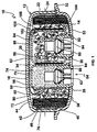
FIG. 1 is a partial cross-sectional side view of an airbag inflator in accordance with one embodiment of the invention. -
FIG. 2 is a partial cross-sectional side view of the airbag inflator ofFIG. 1 but now simplified by not showing gas generant, igniter materials and certain seals, for example. -
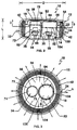
FIG. 3 is a view of the airbag inflator illustrated in -
FIG. 2 taken substantially along the line 3-3 ofFIG. 2 and viewed in the direction of the arrows. -
FIG. 4 is a graphical depiction of tank pressure as a function of time performance realized for the inflator assembly utilized in the Example. -
FIGS. 1 and2 illustrate an adaptive output driver side inflator assembly in accordance with a one embodiment of the invention and generally designated with thereference numeral 10. While the invention will be described hereinafter with particular reference to a driver side airbag inflatable restraint system installation, it will be understood that the invention has general applicability to other types or kinds of airbag assemblies including, for example, passenger side, and side impact airbag assemblies such as for automotive vehicles including vans, pick-up trucks, and particularly automobiles. - The
inflator assembly 10 has a generally cylindrical external outline and includes ahousing construction 12 such as formed of two structural components, i.e., a lower shell orbase portion 14 and an upper shell ordiffuser cap portion 16, such as may desirably be made of aluminum and appropriately joined or fastened together such as by application of an inertia welding operation. Thehousing 12 is illustrated in the general form of a flattened, disk-shaped circular cylinder typically or generally having a length (denominated "L") to diameter (denominated "D") ratio of about 0.5 or less. It will be appreciated that such a sized and shaped housing may most conveniently correspond to the shape of the vehicle steering wheel and can therefore facilitate assembly in an aesthetically pleasing manner. - The
diffusercap portion 16 is in the general form of an inverted bowl and includes atop wall 20 and acylindrical sidewall 22. Thesidewall 22 includes a plurality of spaced, preferably, generally uniformly spacedgas exit ports 24. Thebase portion 14 includes first and second mounting openings, designated by thereference numerals base portion 14 also includes aperipheral bracket 32 that extends radially outward from thehousing 12 and serves to form an interface attachment which is used to attach theinflator assembly 10 to a vehicle the occupants of which are to be protected from injury tending to result from the impact of a collision. - The
housing 12 is configured to define a central, generally cylindricalfirst chamber 34. Thefirst chamber 34 contains or houses a supply of a first gasgenerant material 36, typically in the form of a pyrotechnic, such as known for use in airbag inflators, such as composed of a transition metal amine nitrate with oxidizer and binder, for example. Surrounding the first gasgenerant material 36 is afilter assembly 40 such as includes a combustion screen orfilter 42 such as formed of multiple layers or wraps of metal screen and afilter damper pad 44. Surrounding thefilter 42 and generally adjacent the Inner surface of thesidewall 22 is an adhesive-backedfoil seal 46 which preferably hermetically seals the gasgenerant material 36 within theinflator 10, thereby protecting the gas generant material from ambient conditions, such as including moisture. Theinflator assembly 10 also includes aretainer 50 and an annularbase damper pad 52 serving as construction expedients retaining the inflator assembly components in proper relative arrangement and preventing undesired flow passage through the assembly. - A first igniter assembly, generally designated by the
reference numeral 54, is mounted to thehousing 12 in a location within thefirst chamber 34 via the first mountingopening 26. Thefirst igniter assembly 54 may take the form of a known pyrotechnic initiator device such as includes, as are known in the art, anigniter cup 56 wherein is housed anigniter material 60, a first igniter device orsquib 62, a squib adapter orholder 64 whereby theigniter assembly 54 is mounted to or is mated with thehousing 12 and asquib seal 66, sealing thesquib 62 with theadapter 64. As shown, theigniter cup 56 can take the form of a generally concave member with acap 70 and acylindrical sidewall 72 forming an interior 74. Theigniter cup 56 can be formed of a gas-impermeable material, such as metal, with thecylindrical sidewall 72 including a plurality of spaced, preferably, generally uniformly spaced gas exit orifices 76. Thegas exit orifices 76 are normally (e.g., when the inflator is in a pre-actuation state) covered and the passage of material therethrough prevented by means of a pressure sensitive covering orbarrier 80, such as by means of an adhesive-backed foil seal wrap or the like as is well known in the art. As is known, the covering 80 can be selected to open or rupture upon the application of a pre-determined pressure thereagainst from the interior of theigniter cup 56. - When actuated, ignition of the
igniter material 60 customarily results in an increase in pressure within thecup interior 74 with the subsequent predetermined rupturing or opening of the covering 80 to permit passage of ignition products produced by the combustion of theigniter material 60 through the exit orifices 76, from theigniter assembly 54 to thegas generant material 36 contained within thefirst chamber 34. The resulting contact by or between the ignition products and the gas generant material results in the ignition and reaction of the gas generant material, with gases so produced passing through thefilter 42, rupturing thefoil seal 46 and passing through the gas exit ports 24 (as signified by the arrows A) and out from theinflator assembly 10 into an associated airbag cushion (not shown). As will be appreciated, the contact of ignition products with the gas generant material can appropriately be, either or both, thermal or physical in nature. - In practice, the
igniter assembly 54 can be formed by placing theigniter cup 56 containing theigniter material 60 over theigniter device 62 and theholder 64 and placed at the mountingopening 26. Theigniter assembly 54 may then be joined to thehousing 12 such as by welding theholder 64 to thebase portion 14 at the mountingopening 26. - The
first chamber 34 also houses or contains asecond chamber 82. Thesecond chamber 82 includes agenerant cup 84 wherein is housed a gas generant material, herein designated as the secondgas generant material 86, a second igniterdevice orsquib 90, asecond squib adapter 92 whereby thesecond chamber 82 is mounted to or mates with thehousing 12 and asecond squib seal 94, sealing thesquib 90 with theadapter 92. As shown, thegenerant cup 84 can take the form of a generally concave member with acap 96 and acylindrical sidewall 100 forming an interior 102. - The second
gas generant material 86 is typically in the form of a pyrotechnic material and may either be the same or different in composition, shape, size or form, as compared to the firstgas generant material 36. Thegenerant cup 84 can be formed of a gas-impermeable material, such as metal, with thecylindrical sidewall 100 including a plurality of spaced, preferably, generally uniformly spaced gas exit orifices 104. - The exterior side of the
cylindrical sidewall 100 is covered or wrap with a pressure sensitiveinsulator barrier material 106. Desirably, such aninsulator barrier material 106 can serve one or more of several functions. First, theinsulator barrier material 106 can serve to insulate thesecond chamber 82 and the contents thereof, e.g., the secondgas generant material 86, from at least some of the effects of actuation of thefirst igniter assembly 54 and combustion of the firstgas generant material 36 contained within thefirst chamber 34. As will be appreciated, actuation of thefirst igniter assembly 54 and reaction of the firstgas generant material 36 will generally result in or produce an increase in temperature. - As described above, the
second chamber 82 is housed or contained within thefirst chamber 34 and, in order to minimize space requirements, it is generally preferable that thesecond chamber 82 be in close proximity with theigniter assembly 54. Thus, the inclusion of theinsulator barrier material 106 can serve to minimize or avoid the undesired and possibly detrimental impact of such temperature increase with respect to thesecond chamber 82 such as by preventing or avoiding thesecond chamber 82 from reaching or achieving the autoignition temperature of the gas generant material stored or housed therewithin as a result of contact with the reaction products of thefirst chamber 34. - Further, the
insulator barrier material 106 can serve to normally (e.g., when the inflator 10 is in a preactuation state) cover thegas exit orifices 104 and prevent the passage of material therethrough. Theinsulator barrier material 106 will generally be selected to open or rupture upon the application of a pre-determined pressure thereagainst from the inside of thesecond chamber 82. - As will be appreciated, the insulator barrier material can take various forms such as fiberglass-containing adhesive-backed foil tape. Further, it will be appreciated that if desired separate materials can be used to fulfill, supply or provide the various functions of such an insulator barrier material. For example, the invention can be practiced with an insulator barrier material composed of one or more materials for insulating properties or benefits and an additional one or more materials to effect normal closure or coverage of the gas exit orifices.
- It will be appreciated that an inflator assembly in accordance with the invention can provide operation performance in accordance with selected operating conditions as may be required or desired for particular inflatable restraint system installations and applications. More specifically, an inflator assembly of the invention can be actuated in a manner such that either or both the quantity or rate of inflation gas production can be appropriately varied, such as at the time of a vehicle crash or collision incident, to take into account one or more conditions of occupant presence, as described above. Such inflator performance adaptability results from the subject inflator having two discrete and ballistically isolated chambers of gas generant materials. The subject inflator permits several distinct inflation performance scenarios:
- For example, such an inflator assembly can be operated to have a first stage discharge whereby the
first igniter charge 60 is ignited to produce combustion products which are passed to the firstgas generant chamber 34 to ignite the firstgas generant material 36, such as described above, to produce inflation gas at a first output level without actuating or firing thesecond igniter device 90 or reacting or activating thegas generant material 86 contained in thesecond chamber 82. As will be appreciated, such operation may be desired to provide a minimized or reduced inflator output such as may be desired in an instance of a low speed collision, for example. Alternatively, an inflator assembly in accordance with the invention can be operated such that both the first and second igniter devices, 62 and 90, respectively, are actuated. - As will be appreciated, such operation and ignition of both the first and second igniter devices and first and second gas generant materials can involve the simultaneous or near simultaneous actuation and firing of the first and second Igniter devices (such as may be desired in orderto provide a very rapid inflation and deployment of an associated airbag cushion, as may be desired in response to a high speed or severe vehicle collision) or the sequential actuation and firing of the first and second igniter devices (such as may be desired upon the occurrence of amoderately severe vehicle collision). Further, with such sequential actuation and firing, the time lag or delay between the actuation and firing of the first and second squibs and, in turn, the ignition of the first and second gas generant materials can be tailored to meet the specific requirements for a particular inflatable restraint system installation, as will be appreciated by those skilled in the art. Thus, such inflator assemblies are particularly suited for application as adaptive output inflators such as can be made generally dependent on one or more selected operating conditions such as ambient temperature, occupant presence, seat belt usage and rate of deceleration of the motor vehicle, for example.
- With actuation of the
igniter device 90, theigniter device 90 releases ignition products which ignite thegas generant 86 to produce reaction products which result in an increase in pressure within thecup interior 102 with the subsequent predetermined rupturing or opening of theinsulator barrier material 106 to permit passage of the reaction products through the exit orifices 104 (as signified by the arrows B) and subsequently out through thegas exit ports 24 from theinflator assembly 10 into the associated airbag cushion (not shown). - The
inflator assembly 10, rather than relying on separate filter assemblies for each chamber or stage of the inflator, as Is common with various prior art dual stage inflator devices, employs or utilizes asingle filter assembly 40 for the filtration or treatment, e.g., cooling, of the inflation products produces from both the first and second chambers. Further, such use of a single filter assembly rather the use of two or more filter assemblies can serve to reduce or eliminate the need for the inclusion of multiple filter assembly seals. Still further, theinflator assembly 10 includes a single diffuserratherthan requiring separate diffusers for each chamber or stage contained therein. - As will be appreciated, reductions in the number of parts in an inflator assembly can simplify inflator design, reduce manufacturing and production costs, reduce assembly weight and result in an assembly requiring a smaller volume of space within a vehicle. For example, the use of a single filter or filter assembly for the filtration of the inflation products of the inflation discharge of both the first and second chambers can simplifying system design and result in better utilization of space within the inflator assembly. Thus, facilitating the design of an adaptive inflator assembly to be generally housed within the envelope typically or usually sized and provided for system installations, particularly for driver side inflatable restraint systems, such as sized to be housed within or at a steering wheel column or hub.
- The invention in its broader application is not limited to the use of particular or specific gas generants. As those skilled in the art will appreciate, the invention can be practiced using a wide variety of gas generant materials which meet flame temperature, stability, filterability, toxicity, corrosivity, and gas generation requirements. The invention is believed to be particularly suited for practice in conjunction with the use of pyrotechnic gas generant materials, as are known in the art including, for example, a pyrotechnic composed of a transition metal amine nitrate with oxidizer and binder, as is known in the art.
- As will be appreciated, gas generant materials, e.g., pyrotechnics, useful in the practice of the invention can take various appropriate desired forms, including, for example, various extruded forms as well as granulated materials. The invention, in its broader practice, is not limited to particular or specific forms of gas generant materials.
- Further, it is to be appreciated that while an inflator assembly in accordance with the invention may utilize a gas generant material of the same composition and physical form or parameters as both the first and second gas generant materials, the broader practice of the invention is not so limited. For example, it specifically may be desired that the first gas generant material be relatively slow burning so as to result in or provide a slower or gentler onset of inflation of the associated airbag cushion and that the second gas generant material be relatively quick burning to provide a quicker or faster inflation rate for the associated airbag and such as may be desired in the occurrence of the associated vehicle being involved in a relatively severe collision or crash. Such difference in performance can be realized through the use of gas generant materials of different composition as the first and second gas generant materials. Alternatively or additionally, the first and second gas generant materials can be in different physical form or have different physical parameters, e.g., shape and size. For example, to provide a faster or more rapid burning material it may be desirable to employ a form of the material having an increased or greater surface area.
- The present invention is described in further detail in connection with the following example which illustrates or simulates various aspects involved in the practice of the invention. It is to be understood that all changes that come within the spirit of the invention are desired to be protected and thus the invention is notto be construed as limited by this example.
- Operation of the subject adaptive output inflator was experimentally verified using a steel housing airbag inflator assembly generally similar to the
inflator assembly 10, described above. The test inflator was of a height of 36.4 mm and a diameter of 80 mm. The first chamber contained 43 grams and the second chamber contained 6 grams of a pyrotechnic gas generant material composed of transition metal amine nitrate with oxidizer and binder in the form of a plurality of annular shaped cylinders called "extrudlets." That is, an extrudlet has the form of a cylinder with a hole longitudinally extending therethrough. The pyrotechnic gas generant material extrudlets used in the example had a length and diameter of 0.125 inch and inside diameter of 0.042 inch. The igniter cup of the first chamber contained 2.6 grams of granulated igniter material. - The test inflator apparatus included a steel mesh filter. The gas which evolved from the pyrotechnic was passed through the filter and out from the inflator assembly through the gas exit ports radially located about the inflator in the diffuser portion sidewall.
- The test inflator was attached to a 60 liter closed tank, which was also equipped a pressure transducer to measure changes in tank gas pressure produced by the inflator. The portion of the inflator that vents the evolving gas was wholly contained within the tank so that the volume of the tank was complete closed off from the outside atmosphere. An electronic firing line was connected to each of the squibs of the test inflator so that the different compartments of the test inflator could be appropriately fired either separately, simultaneously or with a selected time delay between the firing of each. The test inflator was operated in a mannerin which: A) only the first chamber was fired and B) both the first and second chambers were fired substantially simultaneously and the tank pressure as a function of time performance realized for by the test inflator assembly are shown in
FIG. 4 . The line A corresponds to the results obtained when only the first chamber was fired, while the line B corresponds to the results obtained when both the first and second chambers were fired substantially simultaneously. - In the Example, the simultaneous firing of both the first and second chambers resulted in both a more rapid increase in pressure within the closed tank and also a higher maximum tank pressure, as compared to operation wherein only the first chamber was fired. As will be appreciated, the gentler or more gradual onset of airbag cushion deployment, as realized when only the first chamber was fired, may be better suited for particular deployment situations such as a relatively low severity collision or in connection with the protection of occupants of smaller size. In contrast, the rapid pressure increase realized with the simultaneous firing of both chambers may be better suited for alternative applications such as a high speed collision in which the occupant is seated in the proper position to be properly cushioned by the airbag, for example.
- As will be appreciated, both the rise rate and maximum pressure realized by the firing of the one or both of the chambers of the inflator can be selected or varied such as by appropriately altering the amount, size, shape and type of pyrotechnic material contained in the fired chamber(s) as well by selectively altering other design parameters. Further, the pressure versus time performance for the inflator can be tuned to the requirements or needs for a particular airbag system installation to appropriately reduce occupant injury and optimize occupant protection.
- The invention illustratively disclosed herein suitably may be practiced in the absence of any element, part, step, component, or ingredient which is not specifically disclosed herein.
- Thus, the invention provides an inflator adapted to provide multiple levels of output performance and which inflator is of a significantly simpler design than inflators previously available. In accordance with at least one embodiment of the invention, an adaptive output inflator particularly for application as an inflator for a driver side inflatable restraint system installation is provided which utilizes a common set of components such as a pressure vessel, filter, and associated seals for each of two or more operating stages and can thus avoid the need for the inclusion of separate such components for each such inflator stage. Thus, simplifying system design and resulting in better utilization of space within an inflator assembly. Consequently, facilitating the design of an adaptive inflator assembly to be generally housed within the envelope typically or usually sized and provided for system installations, particularly for driver side inflatable restraint systems, such as sized to be housed within or at a steering wheel column or hub.
- The invention illustratively disclosed herein suitably may be practiced in the absence of any element, part, step, component, or ingredient which is not specifically disclosed herein.
- While in the foregoing detailed description this invention has been described in relation to certain preferred embodiments thereof, and many details have been set forth for purposes of illustration, it will be apparent to those skilled in the art that the invention is susceptible to additional embodiments and that certain of the details described herein can be varied considerably without departing from the basic principles of the invention.
Claims (13)
- An airbag inflator (10) comprising:a housing (12) having a flattened, disc-shaped circular cylinder form and defining a first chamber (34) which in an at rest state contains a quantity of a first gas generant material (36) ignitable to produce first combustion products, said inflator (10) also including a second chamber (82) which in an at rest state contains a quantity of a second gas generant material (86) ignitable to produce second combustion products, said second chamber (82) including an exit orifice (104) adapted to open to place the second combustion products in fluid communication with the contents of the first chamber (34);a first igniter device (62) operatively associated with the first chamber (34);a second igniter device (90) operatively associated with the second chamber (82), anda single filter assembly (42) for the filtration of inflation products of the first and second chambers (34, 82),characterised in that the second chamber (82) is housed within the first chamber (34) and an auto-ignition insulator barrier (106) covers the exit orifice (104) and is disposed about the second chamber (82) to avoid auto-ignition of the second gas generant material (86) contained within the second chamber (82) upon thermal contact therewith by the first combustion products.
- The airbag Inflator (10) of claim 1 wherein the first gas generant material (36) is a pyrotechnic material.
- The airbag Inflator (10) of claim 1 or 2 wherein the second gas generant material (86) is a pyrotechnic material.
- The airbag Inflator (10) of claims 2 and 3 wherein the pyrotechnic material (36, 86) contained in each of the first and second chambers (34, 82) Is of the same composition.
- The airbag inflator of claim 1, 2 or 3 wherein the first and second gas generant materials (36, 86) differ in one or more of the following aspects:composition, shape, form and size.
- The airbag inflator (10) of claim 2 and 3 wherein the pyrotechnic material (36, 86) contained in each of the first and second chambers (34,82) Is of different composition.
- The airbag inflator of any preceding claim wherein the first igniter device (62) is independently operable from the second igniter device (90).
- The airbag inflator (10) of any preceding claim shaped and sized for driver side placement within a vehicle at the vehicle steering wheel.
- A method of operating an airbag inflator (10) which includes:a housing (12) having a flattened, disc-shaped circular cylinder form and defining a first chamber (34) which in an at rest state contains a quantity of a first gas generant material (36) ignitable to produce first combustion products, said inflator (10) also including a second chamber (82) which in an at rest state contains a quantity of a second gas generant material (86) ignitable to produce second combustion products, said second chamber (82) including an exit orifice (104) adapted to open to place the second combustion products in fluid communication with the contents of the first chamber (34);a first igniter device (62) operatively associated with the first chamber (34); anda second igniter device (90) operatively associated with the second chamber (82);a single filter assembly (42) for the filtration of inflation products of the first and second chambers (34, 82),characterised in that the second chamber (82) is housed within the first chamber (34) and the method includes the step of preventing auto-ignition of the second gas generant material (86) contained within the second chamber (82) upon thermal contact therewith by the first combustion products by means of an auto-ignition insulator barrier (106) disposed about the second chamber (82) and covering the exit orifice (104).
- The method of claim 9 wherein both the first and second Igniter devices (62, 90) are actuated.
- The method of claim 10 wherein the first and second igniter devices (62, 90) are actuated substantially simultaneously.
- The method of claim 10 wherein the second igniter device (90) Is only actuated at a selected time interval subsequent to actuation of the first Igniter device (62).
- The method of claim 9 wherein only the first igniter device (62) is actuated.
Priority Applications (1)
| Application Number | Priority Date | Filing Date | Title |
|---|---|---|---|
| DE69934673.8T DE69934673T3 (en) | 1998-02-18 | 1999-02-10 | INFLATING DEVICE WITH ADAPTIVE GAS FLOW |
Applications Claiming Priority (3)
| Application Number | Priority Date | Filing Date | Title |
|---|---|---|---|
| US27114 | 1998-02-18 | ||
| US09027114 US6032979C1 (en) | 1998-02-18 | 1998-02-18 | Adaptive output inflator |
| PCT/US1999/002772 WO1999042339A1 (en) | 1998-02-18 | 1999-02-10 | Adaptive output inflator |
Publications (4)
| Publication Number | Publication Date |
|---|---|
| EP1056624A1 EP1056624A1 (en) | 2000-12-06 |
| EP1056624A4 EP1056624A4 (en) | 2005-01-19 |
| EP1056624B1 EP1056624B1 (en) | 2007-01-03 |
| EP1056624B2 true EP1056624B2 (en) | 2016-09-28 |
Family
ID=21835773
Family Applications (1)
| Application Number | Title | Priority Date | Filing Date |
|---|---|---|---|
| EP99934270.2A Expired - Lifetime EP1056624B2 (en) | 1998-02-18 | 1999-02-10 | Adaptive output inflator |
Country Status (8)
| Country | Link |
|---|---|
| US (1) | US6032979C1 (en) |
| EP (1) | EP1056624B2 (en) |
| JP (2) | JP2002503584A (en) |
| CN (1) | CN1132751C (en) |
| AU (1) | AU3288199A (en) |
| BR (1) | BR9907942B1 (en) |
| DE (1) | DE69934673T3 (en) |
| WO (1) | WO1999042339A1 (en) |
Families Citing this family (125)
| Publication number | Priority date | Publication date | Assignee | Title |
|---|---|---|---|---|
| US6412017B1 (en) * | 1996-07-01 | 2002-06-25 | Microsoft Corporation | Urgent replication facility |
| WO1998021073A1 (en) * | 1996-11-14 | 1998-05-22 | Nippon Kayaku Kabushiki-Kaisha | Gas generator for air bag |
| DE19654315A1 (en) * | 1996-12-24 | 1998-06-25 | Dynamit Nobel Ag | Hybrid gas generator |
| US6474684B1 (en) * | 1997-04-24 | 2002-11-05 | Talley Defense Systems, Inc. | Dual stage inflator |
| JP3875382B2 (en) * | 1997-12-05 | 2007-01-31 | 本田技研工業株式会社 | Airbag deployment method in airbag device |
| JP2000016226A (en) * | 1998-06-26 | 2000-01-18 | Daicel Chem Ind Ltd | Air bag gas generator and air bag device |
| AU5761099A (en) | 1998-09-28 | 2000-04-17 | Daicel Chemical Industries Ltd. | Gas generator for air bag and air bag device |
| US6412815B1 (en) | 1998-09-28 | 2002-07-02 | Daicel Chemical Industries, Ltd. | Gas generator for air bag and air bag device |
| JP3220443B2 (en) * | 1998-11-30 | 2001-10-22 | ダイセル化学工業株式会社 | Gas generator for airbag and airbag device |
| CZ298910B6 (en) * | 1999-02-05 | 2008-03-12 | Nippon Kayaku Kabushiki-Kaisha | Gas generator |
| DE60035624T2 (en) * | 1999-02-16 | 2007-11-22 | Daicel Chemical Industries, Ltd., Sakai | Multi-stage gas generator for an airbag and airbag device |
| US6547277B1 (en) * | 1999-02-26 | 2003-04-15 | Automotive Systems Laboratory, Inc. | Two chamber gas generator |
| US6290256B1 (en) * | 1999-03-04 | 2001-09-18 | Trw Inc. | Air bag inflator with pressure regulation |
| US6227565B1 (en) | 1999-03-04 | 2001-05-08 | Trw Inc. | Air bag inflator with pressure regulation |
| US6257617B1 (en) | 1999-03-04 | 2001-07-10 | Trw Inc. | Air bag inflator with pressure regulation |
| US6315322B1 (en) | 1999-03-05 | 2001-11-13 | Trw Inc. | Air bag inflator |
| US6701849B2 (en) | 1999-03-05 | 2004-03-09 | Trw Inc. | Dual stage air bag inflator with secondary propellant cap |
| DE10006522B4 (en) | 1999-03-05 | 2018-02-01 | Trw Vehicle Safety Systems Inc. | Inflator for a two-stage airbag |
| US6485051B1 (en) * | 1999-04-28 | 2002-11-26 | Nippon Kayaku Kabushiki-Kaisha | Gas generator |
| WO2000068043A1 (en) | 1999-05-11 | 2000-11-16 | Automotive Systems Laboratory, Inc. | Dual chamber inflator |
| US6364353B2 (en) | 1999-06-07 | 2002-04-02 | Trw Inc. | Dual stage air bag inflator |
| US6237950B1 (en) * | 1999-07-26 | 2001-05-29 | Trw Vehicle Safety Systems Inc. | Staged air bag inflator |
| EP1205363B1 (en) * | 1999-07-28 | 2007-10-10 | Nippon Kayaku Kabushiki Kaisha | Gas generator |
| WO2001013484A2 (en) * | 1999-08-12 | 2001-02-22 | Atlantic Research Corporation | Die cast connector adapter and inflator assembly incorporating the same |
| US6199906B1 (en) * | 1999-08-12 | 2001-03-13 | Breed Automotive Technology, Inc. | Dual stage pyrotechnic inflator |
| JP4860809B2 (en) * | 1999-10-04 | 2012-01-25 | 株式会社ダイセル | Gas generator for airbag and airbag device |
| US7188567B1 (en) | 1999-11-12 | 2007-03-13 | Zodiac Automotive Us Inc. | Gas generation system |
| US6189927B1 (en) * | 1999-12-16 | 2001-02-20 | Autoliv Asp, Inc. | Adaptive output inflator |
| DE20002377U1 (en) * | 2000-02-11 | 2000-08-17 | Trw Airbag Sys Gmbh & Co Kg | Gas generator |
| CN1419504A (en) * | 2000-02-22 | 2003-05-21 | 大赛璐化学工业株式会社 | Airbag gas generator, deflector member, coolant/filter means support member, coolant, and housing |
| JP5008809B2 (en) * | 2000-03-13 | 2012-08-22 | 日本化薬株式会社 | Gas generator |
| DE60128455T2 (en) * | 2000-03-15 | 2007-09-13 | Daicel Chemical Industries, Ltd., Sakai | Gas generator with automatic ignition |
| US6447007B1 (en) * | 2000-03-28 | 2002-09-10 | Atlantic Research Corporation | Compact dual nozzle air bag inflator |
| DE10016167B4 (en) * | 2000-03-31 | 2012-04-26 | Trw Airbag Systems Gmbh & Co. Kg | Gas generator and apparatus for generating gas |
| WO2001083274A1 (en) * | 2000-05-02 | 2001-11-08 | Automotive Systems Laboratory, Inc. | Inflator |
| US6659500B2 (en) | 2000-05-11 | 2003-12-09 | Automotive Systems Laboratory, Inc. | Multi-chamber inflator |
| JP5050298B2 (en) | 2000-05-19 | 2012-10-17 | タカタ株式会社 | Gas generator |
| EP1174313B1 (en) * | 2000-07-18 | 2004-06-16 | Automotive Systems Laboratory Inc. | Multi-chamber inflator |
| EP1361971B1 (en) * | 2001-01-26 | 2008-02-27 | Automotive Systems Laboratory Inc. | Dual chamber inflator |
| JP2002274315A (en) * | 2001-03-21 | 2002-09-25 | Takata Corp | Initiator and gas generator |
| US6860510B2 (en) * | 2001-08-21 | 2005-03-01 | Daicel Chemical Industries, Ltd. | Multistage inflating-type hybrid inflator |
| US6702323B2 (en) * | 2001-09-25 | 2004-03-09 | Trw Inc. | Air bag module with pressure regulator |
| JP4215163B2 (en) | 2002-01-03 | 2009-01-28 | オートモーティブ システムズ ラボラトリー インコーポレーテッド | Air bag inflator |
| US6854764B2 (en) | 2002-02-20 | 2005-02-15 | Autoliv Asp, Inc. | Flexible airbag inflator |
| PL208091B1 (en) * | 2002-02-22 | 2011-03-31 | Nippon Kayaku Kk | Gas generator |
| EP1487676A2 (en) * | 2002-03-26 | 2004-12-22 | Automotive Systems Laboratory, Inc. | Multiple chamber dual stage inflator |
| US6997477B2 (en) * | 2002-04-19 | 2006-02-14 | Automotive Systems Laboratory, Inc. | Inflator |
| US6886469B2 (en) * | 2002-05-17 | 2005-05-03 | Zodiac Automotive Us Inc. | Distributed charge inflator system |
| US7162958B2 (en) | 2002-05-17 | 2007-01-16 | Zodiac Automotive Us Inc. | Distributed charge inflator system |
| US7137341B2 (en) * | 2002-05-17 | 2006-11-21 | Zodiac Automotive Us Inc. | Distributed charge inflator system |
| US20040046373A1 (en) * | 2002-09-09 | 2004-03-11 | Chung Shan Institute Of Science & Technology | Dual stage airbag inflator |
| US7097203B2 (en) * | 2002-09-13 | 2006-08-29 | Automotive Systems Laboratory, Inc. | Inflator |
| JP2004237971A (en) * | 2002-12-09 | 2004-08-26 | Daicel Chem Ind Ltd | Gas generator for air bag |
| US6976704B2 (en) * | 2003-01-30 | 2005-12-20 | Autoliv Asp, Inc. | Adaptive output airbag inflation device |
| US6913285B2 (en) | 2003-05-28 | 2005-07-05 | Autoliv Asp, Inc. | Adaptive inflation performance using magnetic characteristics of gases |
| JP4190353B2 (en) | 2003-06-03 | 2008-12-03 | ダイセル化学工業株式会社 | Multistage ignition gas generator |
| US7150227B2 (en) * | 2003-06-03 | 2006-12-19 | Daicel Chemical Industries, Ltd. | Multi-stage ignition type gas generator |
| CN1863695A (en) * | 2003-08-06 | 2006-11-15 | 日本化药株式会社 | Gas producer |
| US20050098988A1 (en) * | 2003-11-12 | 2005-05-12 | Smith Bradley W. | Pressure-enhanced, adaptive inflator device |
| US7192055B2 (en) * | 2003-11-13 | 2007-03-20 | Automotive Systems Laboratory, Inc. | Pyrotechnic linear inflator |
| US7243946B2 (en) * | 2003-11-18 | 2007-07-17 | Automotive Systems Laboratory, Inc. | Peroxide linear inflator |
| US7080854B2 (en) | 2004-01-13 | 2006-07-25 | Automotive Systems Laboratory, Inc. | Pyrotechnic linear inflator |
| US20050200103A1 (en) * | 2004-02-27 | 2005-09-15 | Burns Sean P. | Pyrotechnic linear inflator with structural enhancement |
| US7267365B2 (en) * | 2004-03-10 | 2007-09-11 | Automotive Systems Laboratory, Inc. | Inflator |
| US7789018B2 (en) * | 2004-04-02 | 2010-09-07 | Automotive Systems Laboratory, Inc. | Gas generator assembly |
| US7293798B2 (en) * | 2004-04-05 | 2007-11-13 | Automotive Systems Laboratory, Inc. | Pyrotechnic linear inflator |
| US7367584B2 (en) * | 2004-04-19 | 2008-05-06 | Automotive Systems Laboratory, Inc. | Gas generating system |
| US7343862B2 (en) * | 2004-05-27 | 2008-03-18 | Automotive Systems Laboratory, Inc. | Gas generating system |
| US7438315B2 (en) * | 2004-05-28 | 2008-10-21 | Automotive Systems Laboratory, Inc. | Inflator and method of assembly |
| US7814838B2 (en) * | 2004-06-28 | 2010-10-19 | Automotive Systems, Laboratory, Inc. | Gas generating system |
| KR100612417B1 (en) * | 2004-07-21 | 2006-08-16 | 삼성전자주식회사 | Pulse-based high-speed low-power gated flip-flop circuit |
| US7275760B2 (en) * | 2004-07-23 | 2007-10-02 | Automotive Systems Laboratory, Inc. | Multi-chamber gas generating system |
| US8622419B2 (en) * | 2004-07-27 | 2014-01-07 | Automotive Systems Laboratory, Inc. | Vehicle component with integral inflator |
| US7237801B2 (en) * | 2004-08-31 | 2007-07-03 | Automotive Systems Laboratory, Inc. | Gas generating system |
| JP2006123641A (en) * | 2004-10-27 | 2006-05-18 | Takata Corp | Outer surface development type airbag device |
| EP1669259B1 (en) * | 2004-12-08 | 2011-06-15 | Delphi Technologies, Inc. | Gas generator |
| DE502004003639D1 (en) * | 2004-12-08 | 2007-06-06 | Delphi Tech Inc | inflator |
| US7934749B2 (en) * | 2005-01-20 | 2011-05-03 | Automotive Systems Laboratory, Inc. | Flexible gas generator |
| US7537240B2 (en) | 2005-02-22 | 2009-05-26 | Automotive Systems Laboratory, Inc. | Gas generating system |
| US7487995B2 (en) | 2005-03-10 | 2009-02-10 | Daicel Chemical Industries, Ltd. | Gas generator for air bag |
| US20060267322A1 (en) * | 2005-05-26 | 2006-11-30 | Trw Vehicle Safety Systems Inc. | Apparatus for inflating an inflatable vehicle occupant restraint |
| US7654565B2 (en) * | 2005-06-02 | 2010-02-02 | Automotive Systems Laboratory, Inc. | Gas generating system |
| US20070057496A1 (en) * | 2005-06-08 | 2007-03-15 | Daicel Chemical Industries, Ltd. | Gas generator for air bag |
| JP2007015675A (en) * | 2005-06-08 | 2007-01-25 | Daicel Chem Ind Ltd | Gas generator for airbag |
| US7413221B2 (en) * | 2005-06-27 | 2008-08-19 | Tk Holdings Inc. | Airbag apparatus with accumulator |
| DE112006001781T5 (en) * | 2005-06-30 | 2008-05-08 | Automotive Systems Laboratory, Inc., Armada | gas generator |
| US7578522B2 (en) * | 2005-08-30 | 2009-08-25 | Daicel Chemical Industries, Ltd. | Gas generator |
| JP4819481B2 (en) | 2005-10-14 | 2011-11-24 | ダイセル化学工業株式会社 | Gas generator for airbag |
| US7806954B2 (en) * | 2005-11-01 | 2010-10-05 | Automotive Systems Laboratory Inc. | Gas generator |
| DE102007019755A1 (en) * | 2006-04-21 | 2007-11-22 | TK Holdings, Inc., Armada | Gas generating system for airbag system and vehicle occupant protection system, comprises first housing made of polymeric material, and pyrotechnic gas generant material |
| US7758709B2 (en) * | 2006-06-21 | 2010-07-20 | Autoliv Asp, Inc. | Monolithic gas generant grains |
| US7591483B2 (en) * | 2006-11-06 | 2009-09-22 | Daicel Chemical Industries, Ltd. | Gas generator for restraining device for vehicle |
| US8444179B2 (en) * | 2006-12-06 | 2013-05-21 | Trw Vehicle Safety Systems Inc. | Dual stage air bag inflator |
| US9193639B2 (en) * | 2007-03-27 | 2015-11-24 | Autoliv Asp, Inc. | Methods of manufacturing monolithic generant grains |
| JP5101923B2 (en) * | 2007-04-18 | 2012-12-19 | 株式会社ダイセル | Gas generator for restraining vehicle personnel |
| US8057611B2 (en) * | 2007-08-13 | 2011-11-15 | Autoliv Asp, Inc. | Multi-composition pyrotechnic grain |
| US8057612B2 (en) * | 2007-08-13 | 2011-11-15 | Autoliv Asp, Inc. | Methods of forming a multi-composition pyrotechnic grain |
| US7950691B1 (en) | 2007-10-31 | 2011-05-31 | Tk Holdings, Inc. | Inflator body with adapter form end |
| US8815029B2 (en) * | 2008-04-10 | 2014-08-26 | Autoliv Asp, Inc. | High performance gas generating compositions |
| US7950693B2 (en) * | 2008-05-20 | 2011-05-31 | Autoliv Asp, Inc. | Dual stage inflator |
| JPWO2010050588A1 (en) * | 2008-10-30 | 2012-03-29 | オートリブ エー・エス・ピー・インク | Inflator for airbag |
| US8808476B2 (en) * | 2008-11-12 | 2014-08-19 | Autoliv Asp, Inc. | Gas generating compositions having glass fibers |
| US8047569B2 (en) * | 2010-03-12 | 2011-11-01 | Autoliv Asp, Inc. | Multi-stage inflator |
| JP5462049B2 (en) * | 2010-03-30 | 2014-04-02 | 株式会社ダイセル | Gas generator |
| US8656838B1 (en) | 2010-09-28 | 2014-02-25 | Tk Holdings, Inc. | Secondary chamber combustion control |
| JP5616815B2 (en) | 2011-02-17 | 2014-10-29 | 株式会社ダイセル | Gas generator seal tape |
| JP5922956B2 (en) * | 2012-03-12 | 2016-05-24 | 株式会社ダイセル | Gas generator |
| JP5763000B2 (en) * | 2012-03-19 | 2015-08-12 | 株式会社ダイセル | Gas generator |
| JP5873373B2 (en) * | 2012-04-02 | 2016-03-01 | 株式会社ダイセル | Gas generator |
| US8556294B1 (en) | 2012-08-22 | 2013-10-15 | Key Safety Systems, Inc | Airbag inflator |
| US9290419B2 (en) | 2012-11-29 | 2016-03-22 | Autoliv Asp, Inc. | Duplex actuation system for inflatable restraints |
| US9010803B2 (en) | 2012-11-29 | 2015-04-21 | Autoliv Asp, Inc. | Duplex firing inflator |
| US9051223B2 (en) | 2013-03-15 | 2015-06-09 | Autoliv Asp, Inc. | Generant grain assembly formed of multiple symmetric pieces |
| US9676366B2 (en) * | 2014-02-20 | 2017-06-13 | Tk Holdings Inc. | Autoigniting, antivirbration airbag inflator pad |
| US9643565B1 (en) | 2014-03-26 | 2017-05-09 | Tk Holdings Inc. | Secondary chamber combustion control mechanism |
| JP6353326B2 (en) | 2014-09-16 | 2018-07-04 | 株式会社ダイセル | Gas generator |
| US9440614B2 (en) | 2015-01-30 | 2016-09-13 | Autoliv Asp, Inc. | Airbag module assembly with cross-car gas diffusion |
| JP6655897B2 (en) | 2015-07-03 | 2020-03-04 | 株式会社ダイセル | Ignition means and gas generator using it |
| JP6477445B2 (en) * | 2015-11-27 | 2019-03-06 | トヨタ自動車株式会社 | Airbag device for vehicle |
| FR3045811B1 (en) * | 2015-12-18 | 2017-12-29 | Livbag Sas | GAS GENERATOR |
| WO2017130735A1 (en) * | 2016-01-26 | 2017-08-03 | 株式会社ダイセル | Gas generator |
| DE102016113732A1 (en) * | 2016-07-26 | 2018-02-01 | Trw Airbag Systems Gmbh | Gas generator with pyrotechnic propellant charge and method for producing the propellant |
| KR102579301B1 (en) * | 2018-12-11 | 2023-09-15 | 현대자동차주식회사 | Passenger airbag inflater and system for vehicle |
| KR102647198B1 (en) | 2018-12-14 | 2024-03-12 | 현대자동차주식회사 | Control method for inflator device of airbag |
| CN111137563B (en) * | 2020-01-17 | 2022-04-01 | 郑州商学院 | Packaging structure for fragile products |
Citations (17)
| Publication number | Priority date | Publication date | Assignee | Title |
|---|---|---|---|---|
| US3868124A (en) † | 1972-09-05 | 1975-02-25 | Olin Corp | Inflating device for use with vehicle safety systems |
| US3877882A (en) † | 1972-07-27 | 1975-04-15 | Talley Industries | Gas generating device |
| US3905515A (en) † | 1972-11-20 | 1975-09-16 | Aerojet General Co | Two-stage, pressure augmented inflator assembly |
| US4561675A (en) † | 1984-04-02 | 1985-12-31 | Morton Thiokol, Inc. | Auto ignition device |
| US4944528A (en) † | 1988-07-19 | 1990-07-31 | Bayern-Chemie, Gesellschaft Fur Flugchemische Antriebe Mbh | Automatic-ignition device for vehicle crash protection device |
| EP0382552A2 (en) † | 1989-02-10 | 1990-08-16 | Morton International, Inc. | Dual chamber gas bag inflator |
| DE4019677A1 (en) † | 1990-06-20 | 1992-01-09 | Bayern Chemie Gmbh Flugchemie | Gas generator for airbag system - operates in two stages to minimise bag kinetic energy |
| US5269561A (en) † | 1992-07-06 | 1993-12-14 | Morton International, Inc. | Vented gas passenger side air bag inflator |
| US5368329A (en) † | 1993-03-03 | 1994-11-29 | Morton International, Inc. | Dual stage inflator |
| US5533750A (en) † | 1995-06-01 | 1996-07-09 | Takata, Inc. | Simplified inflatable restraint module |
| DE29612781U1 (en) † | 1996-07-23 | 1996-11-21 | Trw Repa Gmbh | Pyrotechnic linear drive device for a belt tensioner |
| DE19520847A1 (en) † | 1995-06-08 | 1996-12-12 | Diehl Gmbh & Co | Gas generator for driver's airbag with reduced heat losses |
| DE29616909U1 (en) † | 1996-09-27 | 1997-02-06 | Trw Repa Gmbh | Gas bag cover lockable with snap connection |
| EP0787630A1 (en) † | 1996-01-30 | 1997-08-06 | Morton International, Inc. | Hybrid adaptive driver side inflator |
| WO1997034784A1 (en) † | 1996-03-21 | 1997-09-25 | Dynamit Nobel Gmbh Explosivstoff- Und Systemtechnik | Gas generator for an airbag system |
| EP0803407A1 (en) † | 1996-04-22 | 1997-10-29 | Morton International, Inc. | Variable volume airbag cushion |
| DE29715738U1 (en) † | 1997-09-02 | 1998-01-08 | Trw Repa Gmbh | Set up to attach an airbag in an airbag module |
Family Cites Families (18)
| Publication number | Priority date | Publication date | Assignee | Title |
|---|---|---|---|---|
| DE2224201A1 (en) * | 1972-05-18 | 1973-11-29 | Bayern Chemie Gmbh Flugchemie | SOLID GAS GENERATOR |
| US4998751A (en) * | 1990-03-26 | 1991-03-12 | Morton International, Inc. | Two-stage automotive gas bag inflator using igniter material to delay second stage ignition |
| JP3082426B2 (en) * | 1992-05-21 | 2000-08-28 | タカタ株式会社 | Airbag inflator |
| US5221109A (en) * | 1992-07-23 | 1993-06-22 | Morton International, Inc. | Airbag inflator having vents to terminate inflation |
| US5346254A (en) * | 1993-02-01 | 1994-09-13 | Trw Inc. | Inflator assembly |
| US5431103A (en) * | 1993-12-10 | 1995-07-11 | Morton International, Inc. | Gas generant compositions |
| US5630618A (en) * | 1994-03-18 | 1997-05-20 | Oea, Inc. | Hybrid inflator with a valve |
| US5564743A (en) * | 1995-03-22 | 1996-10-15 | Morton International, Inc. | Multiple stage air bag inflator system |
| US5628528A (en) * | 1995-07-06 | 1997-05-13 | Automotive Systems Laboratory, Inc. | Dual chamber nonazide gas generator |
| US5622380A (en) * | 1995-09-21 | 1997-04-22 | Automotive Systems Laboratory, Inc. | Variable nonazide gas generator having multiple propellant chambers |
| US5658010A (en) * | 1995-09-25 | 1997-08-19 | Trw Vehicle Safety Systems Inc. | Air bag inflator |
| US5582426A (en) * | 1995-10-24 | 1996-12-10 | Trw Vehicle Safety Systems Inc. | Vented ignition cup in stored fluid inflator |
| FR2740545B1 (en) * | 1995-10-30 | 1997-12-05 | Livbag Snc | PYROTECHNIC GAS GENERATOR, VARIABLE FLOW RATE, FOR PROTECTIVE CUSHIONS |
| DE19541584A1 (en) * | 1995-11-08 | 1997-05-15 | Temic Bayern Chem Airbag Gmbh | Arrangement for multi-stage ignition of gas generators |
| US5613702A (en) * | 1996-02-23 | 1997-03-25 | Trw Vehicle Safety Systems Inc. | Apparatus for inflating an inflatable vehicle occupant restraint |
| US5582428A (en) * | 1996-02-28 | 1996-12-10 | Morton International, Inc. | Hybrid adaptive inflator for airbags |
| US5690357A (en) * | 1996-04-25 | 1997-11-25 | Trw Inc. | Dual stage air bag inflator |
| DE19620758A1 (en) * | 1996-05-23 | 1997-11-27 | Temic Bayern Chem Airbag Gmbh | Gas-generator for motor vehicle occupant protection airbag system |
-
1998
- 1998-02-18 US US09027114 patent/US6032979C1/en not_active Expired - Lifetime
-
1999
- 1999-02-10 DE DE69934673.8T patent/DE69934673T3/en not_active Expired - Lifetime
- 1999-02-10 CN CN998027006A patent/CN1132751C/en not_active Expired - Lifetime
- 1999-02-10 EP EP99934270.2A patent/EP1056624B2/en not_active Expired - Lifetime
- 1999-02-10 AU AU32881/99A patent/AU3288199A/en not_active Abandoned
- 1999-02-10 JP JP2000532313A patent/JP2002503584A/en active Pending
- 1999-02-10 BR BRPI9907942-9A patent/BR9907942B1/en not_active IP Right Cessation
- 1999-02-10 WO PCT/US1999/002772 patent/WO1999042339A1/en active IP Right Grant
-
2011
- 2011-12-27 JP JP2011286086A patent/JP5624019B2/en not_active Expired - Lifetime
Patent Citations (17)
| Publication number | Priority date | Publication date | Assignee | Title |
|---|---|---|---|---|
| US3877882A (en) † | 1972-07-27 | 1975-04-15 | Talley Industries | Gas generating device |
| US3868124A (en) † | 1972-09-05 | 1975-02-25 | Olin Corp | Inflating device for use with vehicle safety systems |
| US3905515A (en) † | 1972-11-20 | 1975-09-16 | Aerojet General Co | Two-stage, pressure augmented inflator assembly |
| US4561675A (en) † | 1984-04-02 | 1985-12-31 | Morton Thiokol, Inc. | Auto ignition device |
| US4944528A (en) † | 1988-07-19 | 1990-07-31 | Bayern-Chemie, Gesellschaft Fur Flugchemische Antriebe Mbh | Automatic-ignition device for vehicle crash protection device |
| EP0382552A2 (en) † | 1989-02-10 | 1990-08-16 | Morton International, Inc. | Dual chamber gas bag inflator |
| DE4019677A1 (en) † | 1990-06-20 | 1992-01-09 | Bayern Chemie Gmbh Flugchemie | Gas generator for airbag system - operates in two stages to minimise bag kinetic energy |
| US5269561A (en) † | 1992-07-06 | 1993-12-14 | Morton International, Inc. | Vented gas passenger side air bag inflator |
| US5368329A (en) † | 1993-03-03 | 1994-11-29 | Morton International, Inc. | Dual stage inflator |
| US5533750A (en) † | 1995-06-01 | 1996-07-09 | Takata, Inc. | Simplified inflatable restraint module |
| DE19520847A1 (en) † | 1995-06-08 | 1996-12-12 | Diehl Gmbh & Co | Gas generator for driver's airbag with reduced heat losses |
| EP0787630A1 (en) † | 1996-01-30 | 1997-08-06 | Morton International, Inc. | Hybrid adaptive driver side inflator |
| WO1997034784A1 (en) † | 1996-03-21 | 1997-09-25 | Dynamit Nobel Gmbh Explosivstoff- Und Systemtechnik | Gas generator for an airbag system |
| EP0803407A1 (en) † | 1996-04-22 | 1997-10-29 | Morton International, Inc. | Variable volume airbag cushion |
| DE29612781U1 (en) † | 1996-07-23 | 1996-11-21 | Trw Repa Gmbh | Pyrotechnic linear drive device for a belt tensioner |
| DE29616909U1 (en) † | 1996-09-27 | 1997-02-06 | Trw Repa Gmbh | Gas bag cover lockable with snap connection |
| DE29715738U1 (en) † | 1997-09-02 | 1998-01-08 | Trw Repa Gmbh | Set up to attach an airbag in an airbag module |
Also Published As
| Publication number | Publication date |
|---|---|
| CN1132751C (en) | 2003-12-31 |
| US6032979C1 (en) | 2001-10-16 |
| EP1056624A1 (en) | 2000-12-06 |
| DE69934673D1 (en) | 2007-02-15 |
| JP5624019B2 (en) | 2014-11-12 |
| BR9907942A (en) | 2000-10-24 |
| AU3288199A (en) | 1999-09-06 |
| JP2012062058A (en) | 2012-03-29 |
| US6032979A (en) | 2000-03-07 |
| CN1290221A (en) | 2001-04-04 |
| DE69934673T2 (en) | 2007-10-04 |
| BR9907942B1 (en) | 2008-11-18 |
| DE69934673T3 (en) | 2016-11-24 |
| WO1999042339A1 (en) | 1999-08-26 |
| EP1056624B1 (en) | 2007-01-03 |
| EP1056624A4 (en) | 2005-01-19 |
| JP2002503584A (en) | 2002-02-05 |
Similar Documents
| Publication | Publication Date | Title |
|---|---|---|
| EP1056624B2 (en) | Adaptive output inflator | |
| US6189927B1 (en) | Adaptive output inflator | |
| US7950693B2 (en) | Dual stage inflator | |
| EP1658204B1 (en) | Pyrotechnique side impact inflator | |
| US6189924B1 (en) | Plural stage inflator | |
| EP1509426B1 (en) | Gas generant filter assembly, combination comprising a filter and a closure and an airbag inflator | |
| US20030146611A1 (en) | Adaptive output passenger disk inflator | |
| CA2095595A1 (en) | Time metered response airbag inflator | |
| US5670738A (en) | Hybrid inflator with pop-out diffuser | |
| US6139055A (en) | Adaptive heated stage inflator | |
| EP1613508B1 (en) | Belt and side impact inflator | |
| JPH05319199A (en) | Inflator for air bag | |
| US6976704B2 (en) | Adaptive output airbag inflation device | |
| US20220281405A1 (en) | Dual stage inflator | |
| US11479205B2 (en) | Dual stage inflator | |
| US11603072B2 (en) | Dual stage inflator | |
| KR20240042002A (en) | dual stage inflator |
Legal Events
| Date | Code | Title | Description |
|---|---|---|---|
| PUAI | Public reference made under article 153(3) epc to a published international application that has entered the european phase |
Free format text: ORIGINAL CODE: 0009012 |
|
| 17P | Request for examination filed |
Effective date: 20000911 |
|
| AK | Designated contracting states |
Kind code of ref document: A1 Designated state(s): DE FR GB |
|
| RIN1 | Information on inventor provided before grant (corrected) |
Inventor name: DAHL, KIM, V. Inventor name: MOSSI, G., DEAN |
|
| TPAD | Observations filed by third parties |
Free format text: ORIGINAL CODE: EPIDOS TIPA |
|
| A4 | Supplementary search report drawn up and despatched |
Effective date: 20041206 |
|
| 17Q | First examination report despatched |
Effective date: 20050520 |
|
| GRAP | Despatch of communication of intention to grant a patent |
Free format text: ORIGINAL CODE: EPIDOSNIGR1 |
|
| GRAS | Grant fee paid |
Free format text: ORIGINAL CODE: EPIDOSNIGR3 |
|
| GRAA | (expected) grant |
Free format text: ORIGINAL CODE: 0009210 |
|
| AK | Designated contracting states |
Kind code of ref document: B1 Designated state(s): DE FR GB |
|
| REG | Reference to a national code |
Ref country code: GB Ref legal event code: FG4D |
|
| REF | Corresponds to: |
Ref document number: 69934673 Country of ref document: DE Date of ref document: 20070215 Kind code of ref document: P |
|
| ET | Fr: translation filed | ||
| PLBI | Opposition filed |
Free format text: ORIGINAL CODE: 0009260 |
|
| PLBI | Opposition filed |
Free format text: ORIGINAL CODE: 0009260 |
|
| PLAX | Notice of opposition and request to file observation + time limit sent |
Free format text: ORIGINAL CODE: EPIDOSNOBS2 |
|
| 26 | Opposition filed |
Opponent name: MORDHORST, WOLFGANG Effective date: 20070928 |
|
| 26 | Opposition filed |
Opponent name: TRW AIRBAG SYSTEMS GMBH Effective date: 20071004 Opponent name: MORDHORST, WOLFGANG Effective date: 20070928 |
|
| PLAF | Information modified related to communication of a notice of opposition and request to file observations + time limit |
Free format text: ORIGINAL CODE: EPIDOSCOBS2 |
|
| PLBB | Reply of patent proprietor to notice(s) of opposition received |
Free format text: ORIGINAL CODE: EPIDOSNOBS3 |
|
| PGFP | Annual fee paid to national office [announced via postgrant information from national office to epo] |
Ref country code: GB Payment date: 20081219 Year of fee payment: 11 |
|
| GBPC | Gb: european patent ceased through non-payment of renewal fee |
Effective date: 20100210 |
|
| PG25 | Lapsed in a contracting state [announced via postgrant information from national office to epo] |
Ref country code: GB Free format text: LAPSE BECAUSE OF NON-PAYMENT OF DUE FEES Effective date: 20100210 |
|
| PLAB | Opposition data, opponent's data or that of the opponent's representative modified |
Free format text: ORIGINAL CODE: 0009299OPPO |
|
| PLAB | Opposition data, opponent's data or that of the opponent's representative modified |
Free format text: ORIGINAL CODE: 0009299OPPO |
|
| R26 | Opposition filed (corrected) |
Opponent name: TRW AIRBAG SYSTEMS GMBH Effective date: 20071004 Opponent name: MORDHORST, WOLFGANG Effective date: 20070928 |
|
| R26 | Opposition filed (corrected) |
Opponent name: TRW AIRBAG SYSTEMS GMBH Effective date: 20071004 Opponent name: MORDHORST, WOLFGANG Effective date: 20070928 |
|
| APBM | Appeal reference recorded |
Free format text: ORIGINAL CODE: EPIDOSNREFNO |
|
| APBP | Date of receipt of notice of appeal recorded |
Free format text: ORIGINAL CODE: EPIDOSNNOA2O |
|
| APAH | Appeal reference modified |
Free format text: ORIGINAL CODE: EPIDOSCREFNO |
|
| APBQ | Date of receipt of statement of grounds of appeal recorded |
Free format text: ORIGINAL CODE: EPIDOSNNOA3O |
|
| REG | Reference to a national code |
Ref country code: FR Ref legal event code: PLFP Year of fee payment: 17 |
|
| PGFP | Annual fee paid to national office [announced via postgrant information from national office to epo] |
Ref country code: FR Payment date: 20150203 Year of fee payment: 17 |
|
| PLAB | Opposition data, opponent's data or that of the opponent's representative modified |
Free format text: ORIGINAL CODE: 0009299OPPO |
|
| APBU | Appeal procedure closed |
Free format text: ORIGINAL CODE: EPIDOSNNOA9O |
|
| R26 | Opposition filed (corrected) |
Opponent name: TRW AIRBAG SYSTEMS GMBH Effective date: 20071004 |
|
| RIC2 | Information provided on ipc code assigned after grant |
Ipc: B60R 21/263 20110101ALI20160511BHEP Ipc: B60R 21/264 20060101AFI20160511BHEP |
|
| PUAH | Patent maintained in amended form |
Free format text: ORIGINAL CODE: 0009272 |
|
| STAA | Information on the status of an ep patent application or granted ep patent |
Free format text: STATUS: PATENT MAINTAINED AS AMENDED |
|
| 27A | Patent maintained in amended form |
Effective date: 20160928 |
|
| AK | Designated contracting states |
Kind code of ref document: B2 Designated state(s): DE FR GB |
|
| REG | Reference to a national code |
Ref country code: DE Ref legal event code: R102 Ref document number: 69934673 Country of ref document: DE |
|
| REG | Reference to a national code |
Ref country code: FR Ref legal event code: ST Effective date: 20161028 |
|
| PG25 | Lapsed in a contracting state [announced via postgrant information from national office to epo] |
Ref country code: FR Free format text: LAPSE BECAUSE OF NON-PAYMENT OF DUE FEES Effective date: 20160229 |
|
| PGFP | Annual fee paid to national office [announced via postgrant information from national office to epo] |
Ref country code: DE Payment date: 20180226 Year of fee payment: 20 |
|
| REG | Reference to a national code |
Ref country code: DE Ref legal event code: R071 Ref document number: 69934673 Country of ref document: DE |