EP1061762A1 - Traffic control method for mobile data communication, mobile station device and base station device - Google Patents
Traffic control method for mobile data communication, mobile station device and base station device Download PDFInfo
- Publication number
- EP1061762A1 EP1061762A1 EP99973370A EP99973370A EP1061762A1 EP 1061762 A1 EP1061762 A1 EP 1061762A1 EP 99973370 A EP99973370 A EP 99973370A EP 99973370 A EP99973370 A EP 99973370A EP 1061762 A1 EP1061762 A1 EP 1061762A1
- Authority
- EP
- European Patent Office
- Prior art keywords
- base station
- communication
- mobile
- channel
- common channel
- Prior art date
- Legal status (The legal status is an assumption and is not a legal conclusion. Google has not performed a legal analysis and makes no representation as to the accuracy of the status listed.)
- Granted
Links
Images


Classifications
-
- H—ELECTRICITY
- H04—ELECTRIC COMMUNICATION TECHNIQUE
- H04W—WIRELESS COMMUNICATION NETWORKS
- H04W36/00—Hand-off or reselection arrangements
- H04W36/16—Performing reselection for specific purposes
-
- H—ELECTRICITY
- H04—ELECTRIC COMMUNICATION TECHNIQUE
- H04W—WIRELESS COMMUNICATION NETWORKS
- H04W72/00—Local resource management
- H04W72/02—Selection of wireless resources by user or terminal
-
- H—ELECTRICITY
- H04—ELECTRIC COMMUNICATION TECHNIQUE
- H04W—WIRELESS COMMUNICATION NETWORKS
- H04W72/00—Local resource management
- H04W72/50—Allocation or scheduling criteria for wireless resources
- H04W72/54—Allocation or scheduling criteria for wireless resources based on quality criteria
Definitions
- the present invention relates to a traffic control method, a mobile station device and a base station device for mobile data communications that carry out a traffic control to determine whether or not to allocate a physical channel in a case of carrying out data communications in a mobile communication system using spread signals such as CDMA (Code Division Multiple Access).
- CDMA Code Division Multiple Access
- channels for carrying out actual communications between a radio base station and a mobile radio terminal (mobile station) within a service area managed by the radio base station are classified according to their use as follows.
- one is a common channel and the others are individual channels having a plurality of channels, where the former is a common channel to be used by a plurality of users together, which is used when a traffic from a user is sparse.
- the latter is a channel to be used exclusively by a user, which is set to be used when a communication traffic is dense.
- the data communications are carried out by appropriately switching between these two types of channels depending on a state of traffic from a user.
- the judgement as to whether or not a call admission is possible is made by using a magnitude of an amount of interferences received at the radio base station, an information on a power level transmitted from the radio base station, and their respective prescribed thresholds.
- it is possible to judge a call admission autonomously at the mobile radio terminal by receiving a notification of information on an uplink interference amount and a downlink transmission power, information on thresholds, etc., from the radio base station through a broadcast channel.
- the call admission control that has conventionally been applied at the call level is also applicable to the data communications, but this method cannot suppress data transmission in the common channel, so that there has been a serious problem that no effect can be achieved by the straightforward application. Namely, when the admission is not possible as a result of the judgement, the mobile station will stay in the common channel and carry out data transmission in the common channel, but there has been a possibility of the quality degradation as the transmission radio signals sometimes give rise to interferences with respect to the other users who are communicating in the same band.
- the object of the present invention is to provide a traffic control method, a mobile station device and a base station device for mobile data communications that can realize improvement of communication quality and effective utilization of radio frequencies used in a mobile communication system using spread signals such as CDMA.
- the present invention provides a traffic control method for mobile data communications in a mobile communication system of a scheme using spread signals including CDMA, where two types of communication channels including a common channel and a plurality of individual channels are provided such that the common channel is set to be used by a plurality of users together and each individual channel is set to be used exclusively by one user, the traffic control method for mobile data communications characterized by carrying out a communication using the common channel and the individual channel, between a mobile radio terminal and a radio base station; and carrying out an admission judgement for a shift from the common channel to the individual channel at the radio base station or the mobile radio terminal, when a communication traffic at the mobile radio terminal is shifting from a sparse state to a dense state during the communication.
- the present invention is characterized in that the admission judgement for the shift from the common channel to the individual channel is carried out, at the radio base station according to information on an uplink interference amount which is an amount of received interferences and/or a downlink transmission power level which is a power level transmitted from the radio base station, or at the mobile radio terminal by receiving information on the uplink interference amount and/or the downlink transmission power level that is transmitted from the radio base station and according to the received information on the uplink interference amount and/or the downlink transmission power level.
- an uplink interference amount which is an amount of received interferences and/or a downlink transmission power level which is a power level transmitted from the radio base station
- the mobile radio terminal by receiving information on the uplink interference amount and/or the downlink transmission power level that is transmitted from the radio base station and according to the received information on the uplink interference amount and/or the downlink transmission power level.
- the present invention is characterized in that, when an admission of the shift is not possible as a result of the admission judgement for the shift from the common channel to the individual channel so that the communication is to be kept on the common channel, the radio base station and/or the mobile radio terminal are controlled such that data transmission is not carried out for a prescribed period of time or data transmission is carried out within a prescribed frequency, with regard to the communication.
- the present invention is characterized in that, when an admission of the shift is not possible as a result of the admission judgement for the shift from the common channel to the individual channel so that the communication is to be kept on the common channel, and the shift from the common channel to the individual channel is to be attempted again after controlling the radio base station and/or the mobile radio terminal such that data transmission is not carried out for the prescribed period of time or data transmission is carried out within the prescribed frequency with regard to the communication, a timing for restarting an individual channel set up operation is controlled to be different from other mobile radio terminals.
- the present invention is characterized in that the timing for restarting the individual channel set up operation is determined according to a random number.
- the present invention provides a base station device in a mobile communication system of a scheme using spread signals including CDMA, where two types of communication channels including a common channel and a plurality of individual channels are provided such that the common channel is set to be used by a plurality of users together and each individual channel is set to be used exclusively by one user, the base station device characterized by a communication unit for carrying out a communication using the common channel and the individual channel, with a mobile radio terminal; and an admission judgement unit for carrying out an admission judgement for a shift from the common channel to the individual channel, when a communication traffic state at the mobile radio terminal is shifting from a sparse state to a dense state during the communication.
- the admission judgement unit carries out the admission judgement according to information on an uplink interference amount which is an amount of interferences received at the base station device and/or a downlink transmission power level which is a power level transmitted from the base station device.
- the present invention is characterized by having a data transmission control unit for controlling the base station device and/or the mobile radio terminal such that data transmission is not carried out for a prescribed period of time or data transmission is carried out within a prescribed frequency, with regard to the communication, when an admission of the shift is not possible as a result of the admission judgement for the shift from the common channel to the individual channel so that the communication is to be kept on the common channel.
- the present invention is characterized by having a transmission time control unit for controlling a timing for restarting an individual channel set up operation to be different from other mobile radio terminals, when an admission of the shift is not possible as a result of the admission judgement for the shift from the common channel to the individual channel so that the communication is to be kept on the common channel, and the shift from the common channel to the individual channel is to be attempted again after controlling the base station device and/or the mobile radio terminal such that data transmission is not carried out for the prescribed period of time or data transmission is carried out within the prescribed frequency with regard to the communication.
- the present invention is characterized in that the transmission time control unit determines the timing for restarting the individual channel set up operation according to a random number.
- the present invention provides a mobile station device in a mobile communication system of a scheme using spread signals including CDMA, where two types of communication channels including a common channel and a plurality of individual channels are provided such that the common channel is set to be used by a plurality of users together and each individual channel is set to be used exclusively by one user, the mobile station device characterized by a communication unit for carrying out a communication using the common channel and the individual channel, with a radio base station; and an admission ,judgement unit for carrying out an admission judgement for a shift from the common channel to the individual channel, when a communication traffic state at the mobile station device is shifting from a sparse state to a dense state during the communication.
- the admission judgement unit carries out the admission judgement by receiving information on an uplink interference amount which is an amount of interferences received at the radio base station and/or a downlink transmission power level which is a power level transmitted from the radio base station and according to the received information on the uplink interference amount and/or the downlink transmission power level.
- the present invention is characterized by having a data transmission control unit for controlling the mobile station device and/or the radio base station such that data transmission is not carried out for a prescribed period of time or data transmission is carried out within a prescribed frequency, with regard to the communication, when an admission of the shift is not possible as a result of the admission judgement for the shift from the common channel to the individual channel so that the communication is to be kept on the common channel.
- the present invention is characterized by having a transmission time control unit for controlling a timing for restarting an individual channel set up operation to be different from other mobile radio terminals, when an admission of the shift is not possible as a result of the admission judgement for the shift from the common channel to the individual channel so that the communication is to be kept on the common channel, and the shift from the common channel to the individual channel is to be attempted again after controlling the mobile station device and/or the radio base station such that data transmission is not carried out for the prescribed period of time or data transmission is carried out within the prescribed frequency with regard to the communication.
- the present invention is characterized in that the transmission time control unit determines the timing for restarting the individual channel set up operation according to a random number.
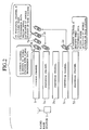
- Fig. 1 shows a schematic configuration of a mobile communication system to which the traffic control method for mobile data communications according to one embodiment of the present invention is applied.
- many radio base stations are distributedly provided to form respective service areas, and many mobile radio terminals (mobile stations) 2 for carrying out data communications with respect to each radio base station 1 are existing inside the service area managed by each radio base station 1 and are actually carrying out the data communications.
- mobile stations mobile stations
- the mobile communication system is provided with two types of radio channels including a common channel 5 and a plurality of individual channels 7a-7d for the purpose of communications between the radio base station 1 and the mobile radio terminal 2, where it is set such that the common channel 5 is used together by a plurality of users who have respective mobile radio terminals 2, and each individual channel 7 is used exclusively by one user who has the mobile radio terminal 2.
- the mobile radio terminal 2 for which data to be transmitted are sparse will use the common channel 5 together with the other mobile radio terminals 2 in the communication between the radio base station 1 and the mobile radio terminal 2.
- the mobile radio terminal 2 for which data to be transmitted are dense will use the individual channel 7 exclusively for the communication with the radio base station 1.
- the individual channel 7 is allocated and a shift to the individual channel 7 is made.
- the activation of these channel shifts can be made by either the mobile radio terminal 2 or the radio base station 1.
- the mobile radio terminals 2a and 2b have sparse data to be transmitted so that they are carrying out the communications using the common channel 5 together.
- the mobile radio terminal 2c had been carrying out the communication using the common channel 5 as data to be transmitted were sparse, but the individual channel 7a is allocated and the communication is carried out using this individual channel 7a as the transmission data became dense in a middle.
- the mobile radio terminal 2d had been carrying out the communication using the individual channel 7c as the transmission data were dense initially, but the communication is continued by returning to the common channel 5 as the transmission data became sparse in a middle.
- a flow of the operation in the mobile communication system of the present embodiment especially a transition of states in the case where the data traffic to be communicated changes while the mobile radio terminal 2 is carrying out the communication using the common channel 5 with the radio base station 1.
- the radio base station 1 and the mobile radio terminal 2 are carrying out the data communication through the common channel 5 (1), but when the mobile radio terminal 2 detects an increase of the data traffic between them, the allocation of the individual channel 7 is requested from the mobile radio terminal 2 to the radio base station 1 (2).
- the radio base station 1 judges whether or not the allocation of the individual channel 7 (an admission of a shift from the common channel to the individual channel) is possible in response to this request, and when it is judged that the allocation is possible, it transmits an individual channel allocation response containing an individual channel specification to the mobile radio terminal 2 (3).
- the mobile radio terminal 2 sets up the individual channel 7 and makes a shift to the individual channel 7, and the mobile ratio terminal 2 and the radio base station 1 continue the data communication through the individual channel 7 (4).
- the mobile radio terminal 2 When the mobile radio terminal 2 detects a decrease of the data traffic during the data communication using the individual channel 7 between the radio base station 1 and the mobile radio terminal 2, the mobile radio terminal 2 requests a release of the individual channel 7 to the radio base station 1 (5).
- the radio base station 1 makes a release response for the individual channel 7 in response to this request (6).
- the individual channel 7 is released by this, and both of them make a shift to the common channel 5 and continue the data communication through the common channel 5 (7).
- the mobile radio terminal 2 When the mobile radio terminal 2 detects an increase of the data traffic at the mobile radio terminal 2 again during the data communication using the common channel 5 by the radio base station 1 and the mobile radio terminal 2, the mobile radio terminal 2 makes an allocation request for the individual channel 7 to the radio base station 1 (8).
- the radio base station 1 judges whether or not the allocation of the individual channel is possible in response to this request, and when it is judged that a shift to the individual channel is not possible as the traffic in the service area is large as a result of this judgement, it transmits an individual channel allocation impossible response to the mobile radio terminal 2 (9).
- the mobile radio terminal 2 sets a timer and continues the data communication through the common channel 5 (10).
- the mobile radio terminal 2 makes an allocation request for the individual channel 7 again (11).
- the radio base station 1 judges whether or not the allocation of the individual channel 7 is possible in response to this request, and when it is judged that a shift to the individual channel 7 is possible as a result of this judgement, it transmits an individual channel allocation response containing a channel specification to the mobile radio terminal 2 (12).
- the mobile radio terminal 2 receives this, sets up the individual channel 7 and makes a shift to the individual channel 7, and the mobile radio terminal 2 and the radio base station 1 continue the data communication through the individual channel 7 (13).
- the detection of an increase or a decrease of the data traffic may be made on the radio base station 1 side, or on each of the radio base station 1 and the mobile radio terminal 2 independently.
- the judgement as to whether or not the allocation of the individual channel is possible may be made on the mobile radio terminal 2 side.
- timer setting and the timer out detection may be carried out on the radio base station 1 side.
- a logical communication path Is set up between the radio base station 1 and the mobile radio terminal 2 (steps S1, S2).
- the radio base station 1 starts transmission of communication signals destined to the mobile radio terminal 2 through the common channel (step S3)
- the mobile radio terminal 2 receives signals from the radio base station 1 and starts transmission of communication signals through the common channel to the radio base station 1 (step S4)
- the radio base station 1 receives signals from the mobile radio terminal 2 (step S5) such that it becomes a data communication state using the common channel between the radio base station 1 and the mobile radio terminal 2 (step S6).
- step S7 the individual channel set up operation is started.
- step S9 measurements of an uplink reception interference level (uplink interference amount) and a downlink transmission power level are carried out (step S9) and whether the uplink reception interference level and the downlink transmission power level are not greater than their respectively corresponding prescribed thresholds or not is judged (step S10).
- step S10 NO when it is judged that the uplink reception interference level and the downlink transmission power level are greater than their respective thresholds (step S10 NO), it is judged that the shift to the individual channel is impossible as the communication traffic within this service area is large and the communication is continued through the common channel, but a limitation on the signal transmission operation through the common channel is set at this point as will be described below (step S11).
- step S11 it is possible to set a limitation only on the signal transmission operation by the radio base station 1, or on the signal transmission operations by both the radio base station 1 and the mobile radio terminal 2. Instead of this, it is also possible to prohibit transmission for a certain period of time. This is done in order to reduce the influence of interferences to the other communications.
- the timer is set according to a random number or the like (step S12), such that the individual channel set up operation will be restarted by the timer out detection at the step S7, and it is returned to the data communication state using the common channel of the step S6.
- the reason for determining the timing for restarting the individual channel set up operation according to a random number or the like is to prevent the increase of interferences by making the timing for restarting the individual channel set up operation different from the other mobile radio terminals. In this way the effectiveness of the frequency utilization in the system can be improved. Note that it is not absolutely necessary to use a random number as long as it is effective for this prevention of the increase of interferences, and it is possible to use other methods such as a method utilizing an ID of the mobile radio terminal for example.
- timer setting at the step S12 and the timer out detection at the step S7 may be carried out at the mobile radio terminal 2 side as in Fig. 3.
- step S10 YES when it is judged that the measured values of the uplink reception interference level and the downlink transmission power level are not greater than their respectively corresponding prescribed thresholds at the step S10 (step S10 YES), it is judged that the shift to the individual channel is possible as the communication traffic within the service area is not so large, and the data communication through the common channel is shifted to the individual channel immediately (step S14).
- the result of the admission judgement for the shift from the common channel to the individual channel (the judgement as to whether or not the individual channel allocation is possible) at the step S10 is notified from the radio base station 1 to the mobile radio terminal 2, and when this admission judgement result indicates that the admission is not possible (step S13 NO), the mobile radio terminal 2 returns to the data communication state using the common channel of the step S6, but when this admission judgement result indicates that the admission is possible (step S13 YES), the data communication through the common channel is shifted to the individual channel immediately (step S15).
- the radio base station 1 After the shift to the individual channel, the radio base station 1 starts transmission of the communication signals destined to the mobile radio terminal 2 through the individual channel (step S16), the mobile radio terminal 2 receives signals from the radio base station 1 and starts transmission of the communication signals through the individual channel to the radio base station 1 (step S17), and the radio base station 1 receives signals from the mobile radio terminal 2 (step S18), such that it becomes a data communication state using the individual channel between the radio base station 1 and the mobile radio terminal 2 (step S19).
- a logical communication path is set up between the radio base station 1 and the mobile radio terminal 2 (steps S21, S22).
- the radio base station 1 starts transmission of communication signals destined to the mobile radio terminal 2 through the common channel (step S23)
- the mobile radio terminal 2 receives signals from the radio base station 1 and starts transmission of communication signals through the common channel to the radio base station 1 (step S24)
- the radio base station 1 receives signals from the mobile radio terminal 2 (step S25) such that it becomes a data communication state using the common channel between the radio base station 1 and the mobile radio terminal 2 (step S26).
- step S27, S28 the individual channel set up operation is started.
- step S29 measurements of an uplink reception interference level (uplink interference amount) and a downlink transmission power level are carried out (step S29) and information on these measured values is notified along with their respectively corresponding prescribed thresholds to the mobile radio terminal 2 through the common channel, and the mobile radio terminal 2 receives this signal from the radio base station 1 (step S30).
- the mobile radio terminal 2 judges whether the uplink reception interference level and the downlink transmission power level are not greater than their respectively corresponding prescribed thresholds or not (step S31).
- step S31 NO when it is judged that the uplink reception interference level and the downlink transmission power level are greater than their respective thresholds (step S31 NO), it is judged that the shift to the individual channel is impossible as the communication traffic within this service area is large and the communication is continued through the common channel, but a limitation on the signal transmission operation through the common channel is set at this point as will be described below (step S32).
- the timer is set according to a random number or the like (step S33), such that the individual channel set up operation will be restarted by the timer out detection at the step S27, and it is returned to the data communication state using the common channel of the step S26.
- the reason for determining the timing for restarting the individual channel set up operation according to a random number or the like is to prevent the increase of interferences by making the timing for restarting the individual channel set up operation different from the other mobile radio terminals. In this way the effectiveness of the frequency utilization in the system can be improved. Note that it is not absolutely necessary to use a random number as long as it is effective for this prevention of the increase of interferences, and it is possible to use other methods such as a method utilizing an ID of the mobile radio terminal for example.
- timer setting at the step S33 and the timer out detection at the step S27 may be carried out at the radio base station 1 side.
- step S31 YES when it is judged that the measured values of the uplink reception interference level and the downlink transmission power level are not greater than their respectively corresponding prescribed thresholds at the step S31 (step S31 YES), it is judged that the shift to the individual channel is possible as the communication traffic within the service area is not so large, and the data communication through the common channel is shifted to the individual channel immediately (step S35).
- the result of the admission judgement for the shift from the common channel to the individual channel (the judgement as to whether or not the individual channel allocation is possible) at the step S31 is notified from the mobile radio terminal 2 to the radio base station 1, and when this admission judgement result indicates that the admission is not possible (step S34 NO), the radio base station 1 returns to the data communication state using the common channel of the step S26, but when this admission judgement result indicates that the admission is possible (step S34 YES), the data communication through the common channel is shifted to the individual channel immediately (step S36).
- the mobile radio terminal 2 After the shift to the individual channel, the mobile radio terminal 2 starts transmission of the communication signals destined to the radio base station 1 through the individual channel (step S37), the radio base station 1 receives signals from the mobile radio terminal 2 and starts transmission of the communication signals through the individual channel to the mobile radio terminal 2 (step S38), and the mobile radio terminal 2 receives signals from the radio base station 1 (step S39), such that it becomes a data communication state using the individual channel between the radio base station 1 and the mobile radio terminal 2 (step S40).
- the radio base station or the mobile radio terminal can be made not to carry out transmission of data for a prescribed period of time or made to carry out transmission of data within a prescribed frequency.
- a value of the prescribed period of time or the prescribed frequency that is used in such a transmission control in the common channel can be made variable or selectable from a plurality of candidates, such that it becomes possible to realize the adaptive control according to the traffic within the service area.
- the respectively corresponding prescribed thresholds for the uplink reception interference level and the downlink transmission power level that are used at the radio base station or the mobile radio terminal can be made variable or different for each radio base station or mobile radio terminal.
- the judgement criteria other than the uplink reception interference level and the downlink transmission power level in this judgement is also possible.
- the number of spread codes available in the mobile communication system is finite so that it is possible to judge that the allocation is not possible when there is no available spread code, or that the allocation is possible otherwise.
- the judgement as to whether or not the allocation is possible is carried out at the mobile station side as in Fig. 5, it suffices to notify information regarding either the remaining number of codes or the presence/absence of the available spread codes to the mobile station.
- the radio base station 1 and the mobile radio terminal 2 detect the increase of the data traffic by monitoring the traffic transmitted by the own station independently, but it is possible to detect the increase of the data traffic by monitoring the traffics of the both stations simultaneously at either one of the radio base station 1 and the mobile radio terminal 2. In any case, a side that detected the increase of the data traffic or the timer out needs to notify the restart of the individual channel set up operation to the other side.
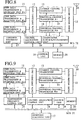
- Fig. 6 shows the first exemplary configuration of the base station device in the present embodiment.
- the base station device comprises a plurality of user data transmission and reception units 11, a data switching unit 12 connected with these user data transmission and reception units 11, one common channel transceiver 13 and a plurality of individual channel transceivers 14 that are connected with this data switching unit 12, a radio modem device 15 connected with these common channel transceiver 13 and individual channel transceivers 14, an antenna 16 connected with this radio modem device 15, an admission judgement unit 17, a channel allocation control unit 18 connected with the data switching unit 12, a control unit 19, a memory 20, and a bus 21 for inter-connecting these admission judgement unit 17, channel allocation control unit 18, control unit 19 and memory 20.
- Each user data transmission and reception unit 11 carries out transmission and reception of user data.
- M sets of the user data transmission and reception units 11 are shown on an assumption that one transmission and reception unit will be used per one user.
- the data switching unit 12 maps data transmitted from the user data transmission and reception unit 11 onto the common channel or the individual channel.
- the common channel transceiver 13 carries out an error correction encoding and a processing for mapping onto radio frames as the processing necessary for transmitting data specified from the data switching unit 12 onto the common channel. It also carries out a processing for extracting from radio frames and decoding data transmitted from the mobile station on the common channel.
- Each individual channel transceiver 14 carries out an error correction encoding and a processing for mapping onto radio frames as the processing necessary for transmitting data specified from the data switching unit 12 onto the individual channel. It also carries out a processing for extracting from radio frames and decoding data transmitted from the mobile station on the individual channel.
- the radio modem device 15 carries out a spreading processing and a radio frequency modulation with respect to radio frames transmitted from the common channel transceiver 13 or the individual channel transceivers 14, and transmits them to the antenna 16. It also carries out a conversion to the baseband frequency and a despreading processing by tuning to radio signals received from the antenna 16.
- the admission judgement unit 17 makes the judgement as to whether or not the allocation of the individual channel is possible (the judgement as to whether or not the admission of the shift from the common channel to the individual channel is possible).
- the channel allocation control unit 18 controls the data switching unit 12 to set correspondences between the user data transmission and reception units 11 and the common channel transceiver 13 or the individual channel transceivers 14.
- the control unit 19 carries out an overall control of the base station device.
- the memory 20 stores and memorizes data.
- Fig. 7 shows the second exemplary configuration of the base station device in the present embodiment.
- This exemplary configuration is an exemplary configuration for the case of using the uplink interference amount and/or the downlink transmission power level, in which an uplink interference amount measurement unit 22 and a downlink transmission power measurement unit 23 that are connected with the radio modem device 15 and the bus 21 are added to the configuration of Fig. 6 described above.
- the uplink interference amount measurement unit 22 carries out a measurement of the uplink interference amount by controlling the radio modem device 15.
- the downlink transmission power measurement unit 23 carries out a measurement of the downlink transmission power by controlling the radio modem device 15.
- Fig. 8 shows the third exemplary configuration of the base station device in the present embodiment.
- This exemplary configuration is an exemplary configuration for the case of using the number of available spread codes and/or the number of available transceivers, in which a transceiver control/management unit 24 that is connected with the common channel transceiver 13, the individual channel transceivers 14 and the bus 21 is added to the configuration of Fig. 6 described above.
- the transceiver control/management unit 24 manages the utilization status of the transceivers, and carries out a management of the spread codes in use by controlling the allocation of the spread codes to the respective transceivers.
- Fig. 9 shows the fourth exemplary configuration of the base station device in the present embodiment.
- This exemplary configuration is an exemplary configuration for the case of controlling the transmission frequency on the common channel, in which a transmission frequency control unit 25 that is connected with the user data transmission and reception units 11 and the bus 21 is added to the configuration of Fig. 6 described above.
- the transmission frequency control unit 25 carries out the transmission frequency control with respect to each user data transmission and reception unit 11.
- Fig. 10 shows the fifth exemplary configuration of the base station device in the present embodiment.
- This exemplary configuration is an exemplary configuration for the case of controlling the signal transmission time on the individual channel, in which a transmission time control unit 26 that is connected with the user data transmission and reception units 11 and the bus 21 is added to the configuration of Fig. 6 described above.
- the transmission time control unit 26 carries out the transmission time control with respect to each user data transmission and reception unit 11.
- Fig. 11 shows the sixth exemplary configuration of the base station device in the present embodiment.
- This exemplary configuration is an exemplary configuration for the case of controlling the signal transmission time on the individual channel according to a random number, in which a random number generator 27 that is connected with the bus 21 is added to the configuration of Fig. 10 described above.
- the random number generator 27 generates a random number for the purpose of the transmission time control by the transmission time control unit 26.
- Fig. 12 shows the first exemplary configuration of the mobile station device in the present embodiment.
- the mobile station device comprises an antenna 31, a radio modem device 32 connected with this antenna 31, a transceiver 33 connected with this radio modem device 32, a user data transmission and reception unit 34 connected with this transceiver 33, a user interface 35 connected with this user data transmission and reception unit 34, a memory 36, a spread code allocation control unit 37 connected with the transceiver 33, an admission judgement unit 38, a control unit 39, and a bus 40 for inter-connecting these memory 36, spread code allocation control unit 37, admission judgement unit 38 and control unit 39.
- the radio modem device 32 carries out a spreading processing and a radio frequency modulation with respect to radio frames transmitted from the transceiver 33, and transmits them to the antenna 31. It also carries out a conversion to the baseband frequency and a despreading processing by tuning to radio signals received from the antenna 31.
- the transceiver 33 carries out an error correction encoding and a processing for mapping onto radio frames as the processing necessary for transmitting data transmitted from the user data transmission and reception unit 34 onto the radio channel. It also carries out a processing for extracting from radio frames and decoding data transmitted from the base station on the radio channel.
- the user data transmission and reception unit 34 carries out transmission and reception of user data.
- the user interface 35 is an interface with respect to a user who operates the mobile station.
- the memory 20 stores and memorizes data.
- the spread code allocation control unit 37 carries out the spread code allocation control by controlling the transceiver 33.
- the admission judgement unit 38 makes the judgement as to whether or not the allocation of the individual channel is possible (the judgement as to whether or not the admission of the shift from the common channel to the individual channel is possible).
- the control unit 39 carries out an overall control of the mobile station device.
- Fig. 13 shows the second exemplary configuration of the mobile station device in the present embodiment.
- This exemplary configuration has a configuration in which a control information receiver 41 that is connected with the radio modem device 32 and a control information processing unit 42 that is connected with this control information receiver 41 and the bus 40 are added to the configuration of Fig. 12 described above.
- the control information receiver 41 receives a control information such as the uplink interference amount and the downlink transmission power that is transmitted from the base station, and the control information processing unit 42 carries out the processing of this received control information.
- Fig. 14 shows the third exemplary configuration of the mobile station device in the present embodiment.
- This exemplary configuration is an exemplary configuration for the case of controlling the transmission frequency on the common channel, in which a transmission frequency control unit 43 that is connected with the user data transmission and reception unit 34 and the bus 40 is added to the configuration of Fig. 12 described above.
- the transmission frequency control unit 43 carries out the transmission frequency control with respect to the user data transmission and reception unit 34.
- Fig. 15 shows the fourth exemplary configuration of the mobile station device in the present embodiment.
- This exemplary configuration is an exemplary configuration for the case of controlling the signal transmission time on the individual channel, in which a transmission time control unit 44 that is connected with the user data transmission and reception unit 34 and the bus 40 is added to the configuration of Fig. 12 described above.
- the transmission time control unit 44 carries out the transmission time control with respect to the user data transmission and reception unit 34.
- Fig. 16 shows the fifth exemplary configuration of the mobile station device in the present embodiment.
- This exemplary configuration is an exemplary configuration for the case of controlling the signal transmission time on the individual channel according to a random number, in which a random number generator 45 that is connected with the bus 40 is added to the configuration of Fig. 15 described above.
- the random number generator 45 generates a random number for the purpose of the transmission time control by the transmission time control unit 44.
- the admission judgement for a shift from the common channel to the individual channel is carried out at the radio, base station or the mobile radio terminal, between the radio base station and the mobile radio terminal, so that it is possible to realize the data traffic scheduling and achieve the improvement of the communication quality and the improvement of the radio band utilization efficiency in the mobile communication system.
- the admission judgement for the shift from the common channel to the individual channel is carried out, at the radio base station according to information on an uplink interference amount and/or a downlink transmission power level, or at the mobile radio terminal according to information on the uplink interference amount and/or the downlink transmission power level that is transmitted from the radio base station, so that it is possible to reduce the interferences with respect to channels that are carrying out the data communications or interferences given to the others, and achieve the improvement of the communication quality.
- a timing for restarting an individual channel set up operation is set to be different from other mobile radio terminals, so that it is possible to reduce the increase of interferences.
- the scheduling of packet data that are generated burstily is realized without requiring a centralized control at the radio base station, so that it is possible to utilize the radio band effectively.
Abstract
Description
- The present invention relates to a traffic control method, a mobile station device and a base station device for mobile data communications that carry out a traffic control to determine whether or not to allocate a physical channel in a case of carrying out data communications in a mobile communication system using spread signals such as CDMA (Code Division Multiple Access).
- In the mobile data communication system using CDMA or the like, channels for carrying out actual communications between a radio base station and a mobile radio terminal (mobile station) within a service area managed by the radio base station are classified according to their use as follows.
- Namely, one is a common channel and the others are individual channels having a plurality of channels, where the former is a common channel to be used by a plurality of users together, which is used when a traffic from a user is sparse. The latter is a channel to be used exclusively by a user, which is set to be used when a communication traffic is dense. The data communications are carried out by appropriately switching between these two types of channels depending on a state of traffic from a user.
- Also, in the mobile communication system using CDMA or the like, the judgement as to whether or not a call admission is possible is made by using a magnitude of an amount of interferences received at the radio base station, an information on a power level transmitted from the radio base station, and their respective prescribed thresholds. Moreover, in the mobile radio terminal, it is possible to judge a call admission autonomously at the mobile radio terminal by receiving a notification of information on an uplink interference amount and a downlink transmission power, information on thresholds, etc., from the radio base station through a broadcast channel.
- However, in the mobile data communications which exchange data while switching a physical channel as described above, conventionally the judgement as to whether or not allocation is possible has not been carried out at a time of switching the physical channel, so that it has not been possible to prevent the quality degradation in the case where data traffics from a plurality of mobile stations are concentrated.
- On the other hand, the call admission control that has conventionally been applied at the call level is also applicable to the data communications, but this method cannot suppress data transmission in the common channel, so that there has been a serious problem that no effect can be achieved by the straightforward application. Namely, when the admission is not possible as a result of the judgement, the mobile station will stay in the common channel and carry out data transmission in the common channel, but there has been a possibility of the quality degradation as the transmission radio signals sometimes give rise to interferences with respect to the other users who are communicating in the same band.
- The object of the present invention is to provide a traffic control method, a mobile station device and a base station device for mobile data communications that can realize improvement of communication quality and effective utilization of radio frequencies used in a mobile communication system using spread signals such as CDMA.
- The present invention provides a traffic control method for mobile data communications in a mobile communication system of a scheme using spread signals including CDMA, where two types of communication channels including a common channel and a plurality of individual channels are provided such that the common channel is set to be used by a plurality of users together and each individual channel is set to be used exclusively by one user, the traffic control method for mobile data communications characterized by carrying out a communication using the common channel and the individual channel, between a mobile radio terminal and a radio base station; and carrying out an admission judgement for a shift from the common channel to the individual channel at the radio base station or the mobile radio terminal, when a communication traffic at the mobile radio terminal is shifting from a sparse state to a dense state during the communication.
- Also, the present invention is characterized in that the admission judgement for the shift from the common channel to the individual channel is carried out, at the radio base station according to information on an uplink interference amount which is an amount of received interferences and/or a downlink transmission power level which is a power level transmitted from the radio base station, or at the mobile radio terminal by receiving information on the uplink interference amount and/or the downlink transmission power level that is transmitted from the radio base station and according to the received information on the uplink interference amount and/or the downlink transmission power level.
- Also, the present invention is characterized in that, when an admission of the shift is not possible as a result of the admission judgement for the shift from the common channel to the individual channel so that the communication is to be kept on the common channel, the radio base station and/or the mobile radio terminal are controlled such that data transmission is not carried out for a prescribed period of time or data transmission is carried out within a prescribed frequency, with regard to the communication.
- Also, the present invention is characterized in that, when an admission of the shift is not possible as a result of the admission judgement for the shift from the common channel to the individual channel so that the communication is to be kept on the common channel, and the shift from the common channel to the individual channel is to be attempted again after controlling the radio base station and/or the mobile radio terminal such that data transmission is not carried out for the prescribed period of time or data transmission is carried out within the prescribed frequency with regard to the communication, a timing for restarting an individual channel set up operation is controlled to be different from other mobile radio terminals.
- Also, the present invention is characterized in that the timing for restarting the individual channel set up operation is determined according to a random number.
- In addition, the present invention provides a base station device in a mobile communication system of a scheme using spread signals including CDMA, where two types of communication channels including a common channel and a plurality of individual channels are provided such that the common channel is set to be used by a plurality of users together and each individual channel is set to be used exclusively by one user, the base station device characterized by a communication unit for carrying out a communication using the common channel and the individual channel, with a mobile radio terminal; and an admission judgement unit for carrying out an admission judgement for a shift from the common channel to the individual channel, when a communication traffic state at the mobile radio terminal is shifting from a sparse state to a dense state during the communication.
- Also, the present invention is characterized in that the admission judgement unit carries out the admission judgement according to information on an uplink interference amount which is an amount of interferences received at the base station device and/or a downlink transmission power level which is a power level transmitted from the base station device.
- Also, the present invention is characterized by having a data transmission control unit for controlling the base station device and/or the mobile radio terminal such that data transmission is not carried out for a prescribed period of time or data transmission is carried out within a prescribed frequency, with regard to the communication, when an admission of the shift is not possible as a result of the admission judgement for the shift from the common channel to the individual channel so that the communication is to be kept on the common channel.
- Also, the present invention is characterized by having a transmission time control unit for controlling a timing for restarting an individual channel set up operation to be different from other mobile radio terminals, when an admission of the shift is not possible as a result of the admission judgement for the shift from the common channel to the individual channel so that the communication is to be kept on the common channel, and the shift from the common channel to the individual channel is to be attempted again after controlling the base station device and/or the mobile radio terminal such that data transmission is not carried out for the prescribed period of time or data transmission is carried out within the prescribed frequency with regard to the communication.
- Also, the present invention is characterized in that the transmission time control unit determines the timing for restarting the individual channel set up operation according to a random number.
- In addition, the present invention provides a mobile station device in a mobile communication system of a scheme using spread signals including CDMA, where two types of communication channels including a common channel and a plurality of individual channels are provided such that the common channel is set to be used by a plurality of users together and each individual channel is set to be used exclusively by one user, the mobile station device characterized by a communication unit for carrying out a communication using the common channel and the individual channel, with a radio base station; and an admission ,judgement unit for carrying out an admission judgement for a shift from the common channel to the individual channel, when a communication traffic state at the mobile station device is shifting from a sparse state to a dense state during the communication.
- Also, the present invention is characterized in that the admission judgement unit carries out the admission judgement by receiving information on an uplink interference amount which is an amount of interferences received at the radio base station and/or a downlink transmission power level which is a power level transmitted from the radio base station and according to the received information on the uplink interference amount and/or the downlink transmission power level.
- Also, the present invention is characterized by having a data transmission control unit for controlling the mobile station device and/or the radio base station such that data transmission is not carried out for a prescribed period of time or data transmission is carried out within a prescribed frequency, with regard to the communication, when an admission of the shift is not possible as a result of the admission judgement for the shift from the common channel to the individual channel so that the communication is to be kept on the common channel.
- Also, the present invention is characterized by having a transmission time control unit for controlling a timing for restarting an individual channel set up operation to be different from other mobile radio terminals, when an admission of the shift is not possible as a result of the admission judgement for the shift from the common channel to the individual channel so that the communication is to be kept on the common channel, and the shift from the common channel to the individual channel is to be attempted again after controlling the mobile station device and/or the radio base station such that data transmission is not carried out for the prescribed period of time or data transmission is carried out within the prescribed frequency with regard to the communication.
- Also, the present invention is characterized in that the transmission time control unit determines the timing for restarting the individual channel set up operation according to a random number.
-
- Fig. 1 is a diagram showing a schematic configuration of a mobile communication system to which a traffic control method for mobile data communications according to one embodiment of the present invention is applied.
- Fig. 2 is a diagram for explaining a method for using a common channel and individual channels in the mobile communication system shown in Fig. 1.
- Fig. 3 is a sequence chart showing a flow of operations in the mobile communication system shown in Fig. 1.
- Fig. 4 is a flow chart showing one exemplary operation procedure in the mobile communication system shown in Fig. 1.
- Fig. 5 is a flow chart showing another exemplary operation procedure in the mobile communication system shown in Fig. 1.
- Fig. 6 is a block diagram showing a first exemplary configuration of a base station device according to one embodiment of the present invention.
- Fig. 7 is a block diagram showing a second exemplary configuration of a base station device according to one embodiment of the present invention.
- Fig. 8 is a block diagram showing a third exemplary configuration of a base station device according to one embodiment of the present invention.
- Fig. 9 is a block diagram showing a fourth exemplary configuration of a base station device according to one embodiment of the present invention.
- Fig. 10 is a block diagram showing a fifth exemplary configuration of a base station device according to one embodiment of the present invention.
- Fig. 11 is a block diagram showing a sixth exemplary configuration of a base station device according to one embodiment of the present invention.
- Fig. 12 is a block diagram showing a first exemplary configuration of a mobile station device according to one embodiment of the present invention.
- Fig. 13 is a block diagram showing a second exemplary configuration of a mobile station device according to one embodiment of the present invention.
- Fig. 14 is a block diagram showing a third exemplary configuration of a mobile station device according to one embodiment of the present invention.
- Fig. 15 is a block diagram showing a fourth exemplary configuration of a mobile station device according to one embodiment of the present invention.
- Fig. 16 is a block diagram showing a fifth exemplary configuration of a mobile station device according to one embodiment of the present invention.
-
- In the following, the embodiment of the present invention will be described using drawings. Fig. 1 shows a schematic configuration of a mobile communication system to which the traffic control method for mobile data communications according to one embodiment of the present invention is applied. In this mobile communication system, many radio base stations are distributedly provided to form respective service areas, and many mobile radio terminals (mobile stations) 2 for carrying out data communications with respect to each
radio base station 1 are existing inside the service area managed by eachradio base station 1 and are actually carrying out the data communications. Note that, in Fig. 1, only oneradio base station 1 and only onemobile radio terminal 2 that is carrying out the data communications with respect to thatradio base station 1 are shown and the others are omitted for the sake of simplicity. - Here, with reference to Fig. 2, the method of using a common channel and individual channels in the mobile communication system shown in Fig. 1 will be described. As shown in Fig. 2, the mobile communication system is provided with two types of radio channels including a
common channel 5 and a plurality ofindividual channels 7a-7d for the purpose of communications between theradio base station 1 and themobile radio terminal 2, where it is set such that thecommon channel 5 is used together by a plurality of users who have respectivemobile radio terminals 2, and eachindividual channel 7 is used exclusively by one user who has themobile radio terminal 2. - In further detail, the
mobile radio terminal 2 for which data to be transmitted are sparse will use thecommon channel 5 together with the othermobile radio terminals 2 in the communication between theradio base station 1 and themobile radio terminal 2. Also, themobile radio terminal 2 for which data to be transmitted are dense will use theindividual channel 7 exclusively for the communication with theradio base station 1. In addition, when data of themobile radio terminal 2 that has been carrying out the communication using thecommon channel 5 become dense, theindividual channel 7 is allocated and a shift to theindividual channel 7 is made. Conversely, when data of themobile radio terminal 2 that has been carrying out communication using theindividual channel 7 become sparse, it is returned to thecommon channel 5. Note that the activation of these channel shifts can be made by either themobile radio terminal 2 or theradio base station 1. - Now Fig. 2 will be described in further detail. The
mobile radio terminals 2a and 2b have sparse data to be transmitted so that they are carrying out the communications using thecommon channel 5 together. Also, the mobile radio terminal 2c had been carrying out the communication using thecommon channel 5 as data to be transmitted were sparse, but theindividual channel 7a is allocated and the communication is carried out using thisindividual channel 7a as the transmission data became dense in a middle. In addition, themobile radio terminal 2d had been carrying out the communication using theindividual channel 7c as the transmission data were dense initially, but the communication is continued by returning to thecommon channel 5 as the transmission data became sparse in a middle. - Next, with reference to the sequence chart shown in Fig. 3, a flow of the operation in the mobile communication system of the present embodiment, especially a transition of states in the case where the data traffic to be communicated changes while the
mobile radio terminal 2 is carrying out the communication using thecommon channel 5 with theradio base station 1. - First, the
radio base station 1 and themobile radio terminal 2 are carrying out the data communication through the common channel 5 (1), but when themobile radio terminal 2 detects an increase of the data traffic between them, the allocation of theindividual channel 7 is requested from themobile radio terminal 2 to the radio base station 1 (2). Theradio base station 1 judges whether or not the allocation of the individual channel 7 (an admission of a shift from the common channel to the individual channel) is possible in response to this request, and when it is judged that the allocation is possible, it transmits an individual channel allocation response containing an individual channel specification to the mobile radio terminal 2 (3). According to this, themobile radio terminal 2 sets up theindividual channel 7 and makes a shift to theindividual channel 7, and themobile ratio terminal 2 and theradio base station 1 continue the data communication through the individual channel 7 (4). - When the
mobile radio terminal 2 detects a decrease of the data traffic during the data communication using theindividual channel 7 between theradio base station 1 and themobile radio terminal 2, themobile radio terminal 2 requests a release of theindividual channel 7 to the radio base station 1 (5). Theradio base station 1 makes a release response for theindividual channel 7 in response to this request (6). Theindividual channel 7 is released by this, and both of them make a shift to thecommon channel 5 and continue the data communication through the common channel 5 (7). - When the
mobile radio terminal 2 detects an increase of the data traffic at themobile radio terminal 2 again during the data communication using thecommon channel 5 by theradio base station 1 and themobile radio terminal 2, themobile radio terminal 2 makes an allocation request for theindividual channel 7 to the radio base station 1 (8). Theradio base station 1 judges whether or not the allocation of the individual channel is possible in response to this request, and when it is judged that a shift to the individual channel is not possible as the traffic in the service area is large as a result of this judgement, it transmits an individual channel allocation impossible response to the mobile radio terminal 2 (9). Upon receiving this response, themobile radio terminal 2 sets a timer and continues the data communication through the common channel 5 (10). - When the timer out is detected at the
mobile radio terminal 2, themobile radio terminal 2 makes an allocation request for theindividual channel 7 again (11). theradio base station 1 judges whether or not the allocation of theindividual channel 7 is possible in response to this request, and when it is judged that a shift to theindividual channel 7 is possible as a result of this judgement, it transmits an individual channel allocation response containing a channel specification to the mobile radio terminal 2 (12). Themobile radio terminal 2 receives this, sets up theindividual channel 7 and makes a shift to theindividual channel 7, and themobile radio terminal 2 and theradio base station 1 continue the data communication through the individual channel 7 (13). - Note that, in Fig. 3, the detection of an increase or a decrease of the data traffic may be made on the
radio base station 1 side, or on each of theradio base station 1 and themobile radio terminal 2 independently. - Also, the judgement as to whether or not the allocation of the individual channel is possible may be made on the
mobile radio terminal 2 side. - Also, the timer setting and the timer out detection may be carried out on the
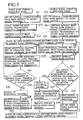
radio base station 1 side. - Next, with reference to the flow chart shown in Fig. 4, one exemplary operation procedure in the mobile communication system of the present embodiment will be described in detail.
- First, when the
radio base station 1 and themobile radio terminal 2 start their operations, a logical communication path Is set up between theradio base station 1 and the mobile radio terminal 2 (steps S1, S2). Thereafter, theradio base station 1 starts transmission of communication signals destined to themobile radio terminal 2 through the common channel (step S3), themobile radio terminal 2 receives signals from theradio base station 1 and starts transmission of communication signals through the common channel to the radio base station 1 (step S4), and theradio base station 1 receives signals from the mobile radio terminal 2 (step S5) such that it becomes a data communication state using the common channel between theradio base station 1 and the mobile radio terminal 2 (step S6). - Next, as the increase of the traffic is detected or the timer out as described below is detected at the
radio base station 1, or as the increase of the traffic is detected at themobile radio terminal 2, the individual channel set up operation is started (steps S7, S8). Then, at theradio base station 1, measurements of an uplink reception interference level (uplink interference amount) and a downlink transmission power level are carried out (step S9) and whether the uplink reception interference level and the downlink transmission power level are not greater than their respectively corresponding prescribed thresholds or not is judged (step S10). As a result, when it is judged that the uplink reception interference level and the downlink transmission power level are greater than their respective thresholds (step S10 NO), it is judged that the shift to the individual channel is impossible as the communication traffic within this service area is large and the communication is continued through the common channel, but a limitation on the signal transmission operation through the common channel is set at this point as will be described below (step S11). Here it is possible to set a limitation only on the signal transmission operation by theradio base station 1, or on the signal transmission operations by both theradio base station 1 and themobile radio terminal 2. Instead of this, it is also possible to prohibit transmission for a certain period of time. This is done in order to reduce the influence of interferences to the other communications. - Next, at the
radio base station 1, the timer is set according to a random number or the like (step S12), such that the individual channel set up operation will be restarted by the timer out detection at the step S7, and it is returned to the data communication state using the common channel of the step S6. Here, the reason for determining the timing for restarting the individual channel set up operation according to a random number or the like is to prevent the increase of interferences by making the timing for restarting the individual channel set up operation different from the other mobile radio terminals. In this way the effectiveness of the frequency utilization in the system can be improved. Note that it is not absolutely necessary to use a random number as long as it is effective for this prevention of the increase of interferences, and it is possible to use other methods such as a method utilizing an ID of the mobile radio terminal for example. - Note that the timer setting at the step S12 and the timer out detection at the step S7 may be carried out at the
mobile radio terminal 2 side as in Fig. 3. - On the other hand, when it is judged that the measured values of the uplink reception interference level and the downlink transmission power level are not greater than their respectively corresponding prescribed thresholds at the step S10 (step S10 YES), it is judged that the shift to the individual channel is possible as the communication traffic within the service area is not so large, and the data communication through the common channel is shifted to the individual channel immediately (step S14).
- The result of the admission judgement for the shift from the common channel to the individual channel (the judgement as to whether or not the individual channel allocation is possible) at the step S10 is notified from the
radio base station 1 to themobile radio terminal 2, and when this admission judgement result indicates that the admission is not possible (step S13 NO), themobile radio terminal 2 returns to the data communication state using the common channel of the step S6, but when this admission judgement result indicates that the admission is possible (step S13 YES), the data communication through the common channel is shifted to the individual channel immediately (step S15). - After the shift to the individual channel, the
radio base station 1 starts transmission of the communication signals destined to themobile radio terminal 2 through the individual channel (step S16), themobile radio terminal 2 receives signals from theradio base station 1 and starts transmission of the communication signals through the individual channel to the radio base station 1 (step S17), and theradio base station 1 receives signals from the mobile radio terminal 2 (step S18), such that it becomes a data communication state using the individual channel between theradio base station 1 and the mobile radio terminal 2 (step S19). - Next, with reference to the flow chart of Fig. 5, the operation procedure in the mobile communication system of the present embodiment for the case where information on the measured values of the uplink reception interference level and the downlink transmission power level that are measured at the
radio base station 1 and their respectively corresponding prescribed thresholds is notified to themobile radio terminal 2 and themobile radio terminal 2 actively carries out the operation up to a start of exchanges for the data communication will be described. - In Fig. 5, similarly as in Fig. 4, first, when the
radio base station 1 and themobile radio terminal 2 start their operations, a logical communication path is set up between theradio base station 1 and the mobile radio terminal 2 (steps S21, S22). Thereafter, theradio base station 1 starts transmission of communication signals destined to themobile radio terminal 2 through the common channel (step S23), themobile radio terminal 2 receives signals from theradio base station 1 and starts transmission of communication signals through the common channel to the radio base station 1 (step S24), and theradio base station 1 receives signals from the mobile radio terminal 2 (step S25) such that it becomes a data communication state using the common channel between theradio base station 1 and the mobile radio terminal 2 (step S26). - Next, as the increase of the traffic is detected or the timer out as described below is detected at the
mobile radio terminal 2, or as the increase of the traffic is detected at theradio base station 1, the individual channel set up operation is started (steps S27, S28). Then, at theradio base station 1, measurements of an uplink reception interference level (uplink interference amount) and a downlink transmission power level are carried out (step S29) and information on these measured values is notified along with their respectively corresponding prescribed thresholds to themobile radio terminal 2 through the common channel, and themobile radio terminal 2 receives this signal from the radio base station 1 (step S30). - Then, the
mobile radio terminal 2 judges whether the uplink reception interference level and the downlink transmission power level are not greater than their respectively corresponding prescribed thresholds or not (step S31). As a result, when it is judged that the uplink reception interference level and the downlink transmission power level are greater than their respective thresholds (step S31 NO), it is judged that the shift to the individual channel is impossible as the communication traffic within this service area is large and the communication is continued through the common channel, but a limitation on the signal transmission operation through the common channel is set at this point as will be described below (step S32). Here it is possible to set a limitation only on the signal transmission operation by themobile radio terminal 2, or on the signal transmission operations by both theradio base station 1 and themobile radio terminal 2. Instead of this, it is also possible to prohibit transmission for a certain period of time. This is done in order to reduce the influence of interferences to the other communications. - Next, at
mobile radio terminal 2, the timer is set according to a random number or the like (step S33), such that the individual channel set up operation will be restarted by the timer out detection at the step S27, and it is returned to the data communication state using the common channel of the step S26. Here, the reason for determining the timing for restarting the individual channel set up operation according to a random number or the like is to prevent the increase of interferences by making the timing for restarting the individual channel set up operation different from the other mobile radio terminals. In this way the effectiveness of the frequency utilization in the system can be improved. Note that it is not absolutely necessary to use a random number as long as it is effective for this prevention of the increase of interferences, and it is possible to use other methods such as a method utilizing an ID of the mobile radio terminal for example. - Note that the timer setting at the step S33 and the timer out detection at the step S27 may be carried out at the
radio base station 1 side. - On the other hand, when it is judged that the measured values of the uplink reception interference level and the downlink transmission power level are not greater than their respectively corresponding prescribed thresholds at the step S31 (step S31 YES), it is judged that the shift to the individual channel is possible as the communication traffic within the service area is not so large, and the data communication through the common channel is shifted to the individual channel immediately (step S35).
- The result of the admission judgement for the shift from the common channel to the individual channel (the judgement as to whether or not the individual channel allocation is possible) at the step S31 is notified from the
mobile radio terminal 2 to theradio base station 1, and when this admission judgement result indicates that the admission is not possible (step S34 NO), theradio base station 1 returns to the data communication state using the common channel of the step S26, but when this admission judgement result indicates that the admission is possible (step S34 YES), the data communication through the common channel is shifted to the individual channel immediately (step S36). - After the shift to the individual channel, the
mobile radio terminal 2 starts transmission of the communication signals destined to theradio base station 1 through the individual channel (step S37), theradio base station 1 receives signals from themobile radio terminal 2 and starts transmission of the communication signals through the individual channel to the mobile radio terminal 2 (step S38), and themobile radio terminal 2 receives signals from the radio base station 1 (step S39), such that it becomes a data communication state using the individual channel between theradio base station 1 and the mobile radio terminal 2 (step S40). - The above description of the operation procedure is related to a part of the processing of Fig. 3, but the operations related to the other state changes shown in Fig. 3 are also executed by procedures similar to Fig. 4 and Fig. 5 described above.
- In the operation procedures of Fig. 4 and Fig. 5 described above, as the limitation on the operations to transmit signals through the common channel that is to be set after judging whether or not the allocation of the individual channel is possible at the radio base station or the mobile radio terminal and keeping the communication on the common channel in the case where the allocation is not possible, the radio base station or the mobile radio terminal can be made not to carry out transmission of data for a prescribed period of time or made to carry out transmission of data within a prescribed frequency. By carrying out such a transmission control in the common channel, it becomes possible to prevent the degradation of the communication quality of the other users who are communicating in the same frequency band.
- Note that a value of the prescribed period of time or the prescribed frequency that is used in such a transmission control in the common channel can be made variable or selectable from a plurality of candidates, such that it becomes possible to realize the adaptive control according to the traffic within the service area.
- Also, the respectively corresponding prescribed thresholds for the uplink reception interference level and the downlink transmission power level that are used at the radio base station or the mobile radio terminal can be made variable or different for each radio base station or mobile radio terminal.
- Note that, in the operation procedures of Fig. 4 and Fig. 5 described above, whether the traffic within the service area is large or not is judged using both the uplink reception interference level and the downlink transmission power level, but it is not absolutely necessary to use both of them together, and it is possible to judge whether the traffic within the service area is large or not using only either one of the uplink reception interference level and the downlink transmission power level.
- In addition, it is also possible to use the judgement criteria other than the uplink reception interference level and the downlink transmission power level in this judgement as to whether or not the allocation is possible. For example, the number of spread codes available in the mobile communication system is finite so that it is possible to judge that the allocation is not possible when there is no available spread code, or that the allocation is possible otherwise. In this case, in the scheme where the judgement as to whether or not the allocation is possible is carried out at the mobile station side as in Fig. 5, it suffices to notify information regarding either the remaining number of codes or the presence/absence of the available spread codes to the mobile station. Else, as another example, it is possible to judge that the allocation is not possible when there is no available transceiver, or that the allocation is possible otherwise. In this case, in the scheme where the judgement as to whether or not the allocation is possible is carried out at the mobile station side as in Fig. 5, it suffices to notify information regarding either the remaining number of transceivers or the presence/absence of the available transceivers to the mobile station.
- Also, in the operation procedures of Fig. 4 and Fig. 5 described above, the
radio base station 1 and themobile radio terminal 2 detect the increase of the data traffic by monitoring the traffic transmitted by the own station independently, but it is possible to detect the increase of the data traffic by monitoring the traffics of the both stations simultaneously at either one of theradio base station 1 and themobile radio terminal 2. In any case, a side that detected the increase of the data traffic or the timer out needs to notify the restart of the individual channel set up operation to the other side. - Next, with references to Fig. 6 to Fig. 11, exemplary configurations of a base station device in the present embodiment will be described.
- Fig. 6 shows the first exemplary configuration of the base station device in the present embodiment. In this exemplary configuration, the base station device comprises a plurality of user data transmission and
reception units 11, adata switching unit 12 connected with these user data transmission andreception units 11, onecommon channel transceiver 13 and a plurality ofindividual channel transceivers 14 that are connected with thisdata switching unit 12, aradio modem device 15 connected with thesecommon channel transceiver 13 andindividual channel transceivers 14, anantenna 16 connected with thisradio modem device 15, anadmission judgement unit 17, a channelallocation control unit 18 connected with thedata switching unit 12, acontrol unit 19, amemory 20, and abus 21 for inter-connecting theseadmission judgement unit 17, channelallocation control unit 18,control unit 19 andmemory 20. - Each user data transmission and
reception unit 11 carries out transmission and reception of user data. In Fig. 6, M sets of the user data transmission andreception units 11 are shown on an assumption that one transmission and reception unit will be used per one user. - The
data switching unit 12 maps data transmitted from the user data transmission andreception unit 11 onto the common channel or the individual channel. - The
common channel transceiver 13 carries out an error correction encoding and a processing for mapping onto radio frames as the processing necessary for transmitting data specified from thedata switching unit 12 onto the common channel. It also carries out a processing for extracting from radio frames and decoding data transmitted from the mobile station on the common channel. - Each
individual channel transceiver 14 carries out an error correction encoding and a processing for mapping onto radio frames as the processing necessary for transmitting data specified from thedata switching unit 12 onto the individual channel. It also carries out a processing for extracting from radio frames and decoding data transmitted from the mobile station on the individual channel. - The
radio modem device 15 carries out a spreading processing and a radio frequency modulation with respect to radio frames transmitted from thecommon channel transceiver 13 or theindividual channel transceivers 14, and transmits them to theantenna 16. It also carries out a conversion to the baseband frequency and a despreading processing by tuning to radio signals received from theantenna 16. - The
admission judgement unit 17 makes the judgement as to whether or not the allocation of the individual channel is possible (the judgement as to whether or not the admission of the shift from the common channel to the individual channel is possible). - The channel
allocation control unit 18 controls thedata switching unit 12 to set correspondences between the user data transmission andreception units 11 and thecommon channel transceiver 13 or theindividual channel transceivers 14. - The
control unit 19 carries out an overall control of the base station device. - The
memory 20 stores and memorizes data. - Fig. 7 shows the second exemplary configuration of the base station device in the present embodiment. This exemplary configuration is an exemplary configuration for the case of using the uplink interference amount and/or the downlink transmission power level, in which an uplink interference amount measurement unit 22 and a downlink transmission
power measurement unit 23 that are connected with theradio modem device 15 and thebus 21 are added to the configuration of Fig. 6 described above. - The uplink interference amount measurement unit 22 carries out a measurement of the uplink interference amount by controlling the
radio modem device 15. - The downlink transmission
power measurement unit 23 carries out a measurement of the downlink transmission power by controlling theradio modem device 15. - Fig. 8 shows the third exemplary configuration of the base station device in the present embodiment. This exemplary configuration is an exemplary configuration for the case of using the number of available spread codes and/or the number of available transceivers, in which a transceiver control/
management unit 24 that is connected with thecommon channel transceiver 13, theindividual channel transceivers 14 and thebus 21 is added to the configuration of Fig. 6 described above. - The transceiver control/
management unit 24 manages the utilization status of the transceivers, and carries out a management of the spread codes in use by controlling the allocation of the spread codes to the respective transceivers. - Fig. 9 shows the fourth exemplary configuration of the base station device in the present embodiment. This exemplary configuration is an exemplary configuration for the case of controlling the transmission frequency on the common channel, in which a transmission
frequency control unit 25 that is connected with the user data transmission andreception units 11 and thebus 21 is added to the configuration of Fig. 6 described above. - The transmission
frequency control unit 25 carries out the transmission frequency control with respect to each user data transmission andreception unit 11. - Fig. 10 shows the fifth exemplary configuration of the base station device in the present embodiment. This exemplary configuration is an exemplary configuration for the case of controlling the signal transmission time on the individual channel, in which a transmission
time control unit 26 that is connected with the user data transmission andreception units 11 and thebus 21 is added to the configuration of Fig. 6 described above. - The transmission
time control unit 26 carries out the transmission time control with respect to each user data transmission andreception unit 11. - Fig. 11 shows the sixth exemplary configuration of the base station device in the present embodiment. This exemplary configuration is an exemplary configuration for the case of controlling the signal transmission time on the individual channel according to a random number, in which a
random number generator 27 that is connected with thebus 21 is added to the configuration of Fig. 10 described above. - The
random number generator 27 generates a random number for the purpose of the transmission time control by the transmissiontime control unit 26. - Next, with references to Fig. 12 to Fig. 16, exemplary configurations of a mobile station device in the present embodiment will be described.
- Fig. 12 shows the first exemplary configuration of the mobile station device in the present embodiment. In this exemplary configuration, the mobile station device comprises an
antenna 31, aradio modem device 32 connected with thisantenna 31, atransceiver 33 connected with thisradio modem device 32, a user data transmission andreception unit 34 connected with thistransceiver 33, auser interface 35 connected with this user data transmission andreception unit 34, amemory 36, a spread codeallocation control unit 37 connected with thetransceiver 33, anadmission judgement unit 38, acontrol unit 39, and abus 40 for inter-connecting thesememory 36, spread codeallocation control unit 37,admission judgement unit 38 andcontrol unit 39. - The
radio modem device 32 carries out a spreading processing and a radio frequency modulation with respect to radio frames transmitted from thetransceiver 33, and transmits them to theantenna 31. It also carries out a conversion to the baseband frequency and a despreading processing by tuning to radio signals received from theantenna 31. - The
transceiver 33 carries out an error correction encoding and a processing for mapping onto radio frames as the processing necessary for transmitting data transmitted from the user data transmission andreception unit 34 onto the radio channel. It also carries out a processing for extracting from radio frames and decoding data transmitted from the base station on the radio channel. - The user data transmission and
reception unit 34 carries out transmission and reception of user data. - The
user interface 35 is an interface with respect to a user who operates the mobile station. - The
memory 20 stores and memorizes data. - The spread code
allocation control unit 37 carries out the spread code allocation control by controlling thetransceiver 33. - The
admission judgement unit 38 makes the judgement as to whether or not the allocation of the individual channel is possible (the judgement as to whether or not the admission of the shift from the common channel to the individual channel is possible). - The
control unit 39 carries out an overall control of the mobile station device. - Fig. 13 shows the second exemplary configuration of the mobile station device in the present embodiment. This exemplary configuration has a configuration in which a
control information receiver 41 that is connected with theradio modem device 32 and a controlinformation processing unit 42 that is connected with thiscontrol information receiver 41 and thebus 40 are added to the configuration of Fig. 12 described above. - The
control information receiver 41 receives a control information such as the uplink interference amount and the downlink transmission power that is transmitted from the base station, and the controlinformation processing unit 42 carries out the processing of this received control information. - Fig. 14 shows the third exemplary configuration of the mobile station device in the present embodiment. This exemplary configuration is an exemplary configuration for the case of controlling the transmission frequency on the common channel, in which a transmission
frequency control unit 43 that is connected with the user data transmission andreception unit 34 and thebus 40 is added to the configuration of Fig. 12 described above. - The transmission
frequency control unit 43 carries out the transmission frequency control with respect to the user data transmission andreception unit 34. - Fig. 15 shows the fourth exemplary configuration of the mobile station device in the present embodiment. This exemplary configuration is an exemplary configuration for the case of controlling the signal transmission time on the individual channel, in which a transmission
time control unit 44 that is connected with the user data transmission andreception unit 34 and thebus 40 is added to the configuration of Fig. 12 described above. - The transmission
time control unit 44 carries out the transmission time control with respect to the user data transmission andreception unit 34. - Fig. 16 shows the fifth exemplary configuration of the mobile station device in the present embodiment. This exemplary configuration is an exemplary configuration for the case of controlling the signal transmission time on the individual channel according to a random number, in which a
random number generator 45 that is connected with thebus 40 is added to the configuration of Fig. 15 described above. - The
random number generator 45 generates a random number for the purpose of the transmission time control by the transmissiontime control unit 44. - As described above, according to the present invention, when a communication traffic at the mobile radio terminal is shifting from a sparse state to a dense state, the admission judgement for a shift from the common channel to the individual channel is carried out at the radio, base station or the mobile radio terminal, between the radio base station and the mobile radio terminal, so that it is possible to realize the data traffic scheduling and achieve the improvement of the communication quality and the improvement of the radio band utilization efficiency in the mobile communication system.
- Also, according to the present invention, the admission judgement for the shift from the common channel to the individual channel is carried out, at the radio base station according to information on an uplink interference amount and/or a downlink transmission power level, or at the mobile radio terminal according to information on the uplink interference amount and/or the downlink transmission power level that is transmitted from the radio base station, so that it is possible to reduce the interferences with respect to channels that are carrying out the data communications or interferences given to the others, and achieve the improvement of the communication quality.
- In addition, according to the present invention, when an admission of the shift is not possible as a result of the admission judgement for the shift from the common channel to the individual channel so that the communication is to be kept on the common channel, data transmission is not carried out for a prescribed period of time or data transmission is carried out within a prescribed frequency, so that it is possible to prevent the degradation of the communication quality of the other users who are communicating in the same frequency band.
- In addition, according to the present invention, when the shift from the common channel to the individual channel is to be attempted again after the admission of the shift is judged as not possible once, a timing for restarting an individual channel set up operation is set to be different from other mobile radio terminals, so that it is possible to reduce the increase of interferences.
- Also, according to the present invention, because of the sequential control for each channel at the radio base station or the autonomous control at the mobile radio terminal, the scheduling of packet data that are generated burstily is realized without requiring a centralized control at the radio base station, so that it is possible to utilize the radio band effectively.
Claims (15)
- A traffic control method for mobile data communications in a mobile communication system of a scheme using spread signals including CDMA, where two types of communication channels including a common channel and a plurality of individual channels are provided such that the common channel is set to be used by a plurality of users together and each individual channel is set to be used exclusively by one user, the traffic control method for mobile data communications characterized bycarrying out a communication using the common channel and the individual channel, between a mobile radio terminal and a radio base station; andcarrying out an admission judgement for a shift from the common channel to the individual channel at the radio base station or the mobile radio terminal, when a communication traffic at the mobile radio terminal is shifting from a sparse state to a dense state during the communication.
- The traffic control method for mobile data communications as described in claim 1, characterized in that the admission judgement for the shift from the common channel to the individual channel is carried out, at the radio base station according to information on an uplink interference amount which is an amount of received interferences and/or a downlink transmission power level which is a power level transmitted from the radio base station, or at the mobile radio terminal by receiving information on the uplink interference amount and/or the downlink transmission power level that is transmitted from the radio base station and according to the received information on the uplink interference amount and/or the downlink transmission power level.
- The traffic control method in mobile data communications as described in claim 1, characterized in that, when an admission of the shift is not possible as a result of the admission judgement for the shift from the common channel to the individual channel so that the communication is to be kept on the common channel, the radio base station and/or the mobile radio terminal are controlled such that data transmission is not carried out for a prescribed period of time or data transmission is carried out within a prescribed frequency, with regard to the communication.
- The traffic control method in mobile data communications as described in claim 3, characterized in that, when an admission of the shift is not possible as a result of the admission judgement for the shift from the common channel to the individual channel so that the communication is to be kept on the common channel, and the shift from the common channel to the individual channel is to be attempted again after controlling the radio base station and/or the mobile radio terminal such that data transmission is not carried out for the prescribed period of time or data transmission is carried out within the prescribed frequency with regard to the communication, a timing for restarting an individual channel set up operation is controlled to be different from other mobile radio terminals.
- The traffic control method in mobile data communications as described in claim 4, characterized in that the timing for restarting the individual channel set up operation is determined according to a random number.
- A base station device in a mobile communication system of a scheme using spread signals including CDMA, where two types of communication channels including a common channel and a plurality of individual channels are provided such that the common channel is set to be used by a plurality of users together and each individual channel is set to be used exclusively by one user, the base station device characterized bya communication unit for carrying out a communication using the common channel and the individual channel, with a mobile radio terminal; andan admission judgement unit for carrying out an admission judgement for a shift from the common channel to the individual channel, when a communication traffic state at the mobile radio terminal is shifting from a sparse state to a dense state during the communication.
- The base station device as described in claim 6, characterized in that the admission judgement unit carries out the admission judgement according to information on an uplink interference amount which is an amount of interferences received at the base station device and/or a downlink transmission power level which is a power level transmitted from the base station device.
- The base station device as described in claim 6, characterized by having a data transmission control unit for controlling the base station device and/or the mobile radio terminal such that data transmission is not carried out for a prescribed period of time or data transmission is carried out within a prescribed frequency, with regard to the communication, when an admission of the shift is not possible as a result of the admission judgement for the shift from the common channel to the individual channel so that the communication is to be kept on the common channel.
- The base station device as described in claim 8, characterized by having a transmission time control unit for controlling a timing for restarting an individual channel set up operation to be different from other mobile radio terminals, when an admission of the shift is not possible as a result of the admission judgement for the shift from the common channel to the individual channel so that the communication is to be kept on the common channel, and the shift from the common channel to the individual channel is to be attempted again after controlling the base station device and/or the mobile radio terminal such that data transmission is not carried out for the prescribed period of time or data transmission is carried out within the prescribed frequency with regard to the communication.
- The base station device as described in claim 9, characterized in that the transmission time control unit determines the timing for restarting the individual channel set up operation according to a random number.
- A mobile station device in a mobile communication system of a scheme using spread signals including CDMA, where two types of communication channels including a common channel and a plurality of individual channels are provided such that the common channel is set to be used by a plurality of users together and each individual channel is set to be used exclusively by one user, the mobile station device characterized bya communication unit for carrying out a communication using the common channel and the individual channel, with a radio base station; andan admission judgement unit for carrying out an admission judgement for a shift from the common channel to the individual channel, when a communication traffic state at the mobile station device is shifting from a sparse state to a dense state during the communication.
- The mobile station device as described in claim 11, characterized in that the admission judgement unit carries out the admission judgement by receiving information on an uplink interference amount which is an amount of interferences received at the radio base station and/or a downlink transmission power level which is a power level transmitted from the radio base station and according to the received information on the uplink interference amount and/or the downlink transmission power level.
- The mobile station device as described in claim 11, characterized by having a data transmission control unit for controlling the mobile station device and/or the radio base station such that data transmission is not carried out for a prescribed period of time or data transmission is carried out within a prescribed frequency, with regard to the communication, when an admission of the shift is not possible as a result of the admission judgement for the shift from the common channel to the individual channel so that the communication is to be kept on the common channel.
- The mobile station device as described in claim 13, characterized by having a transmission time control unit for controlling a timing for restarting an individual channel set up operation to be different from other mobile radio terminals, when an admission of the shift is not possible as a result of the admission judgement for the shift from the common channel to the individual channel so that the communication is to be kept on the common channel, and the shift from the common channel to the individual channel is to be attempted again after controlling the mobile station device and/or the radio base station such that data transmission is not carried out for the prescribed period of time or data transmission is carried out within the prescribed frequency with regard to the communication.
- The mobile station device as described in claim 14, characterized in that the transmission time control unit determines the timing for restarting the individual channel set up operation according to a random number.
Applications Claiming Priority (3)
| Application Number | Priority Date | Filing Date | Title |
|---|---|---|---|
| JP34747098 | 1998-12-07 | ||
| JP34747098 | 1998-12-07 | ||
| PCT/JP1999/006814 WO2000035235A1 (en) | 1998-12-07 | 1999-12-06 | Traffic control method for mobile data communication, mobile station device and base station device |
Publications (3)
| Publication Number | Publication Date |
|---|---|
| EP1061762A1 true EP1061762A1 (en) | 2000-12-20 |
| EP1061762A4 EP1061762A4 (en) | 2005-07-27 |
| EP1061762B1 EP1061762B1 (en) | 2007-06-13 |
Family
ID=18390449
Family Applications (1)
| Application Number | Title | Priority Date | Filing Date |
|---|---|---|---|
| EP99973370A Expired - Lifetime EP1061762B1 (en) | 1998-12-07 | 1999-12-06 | Traffic control method for mobile data communication, mobile station device and base station device |
Country Status (6)
| Country | Link |
|---|---|
| US (1) | US7304970B1 (en) |
| EP (1) | EP1061762B1 (en) |
| JP (1) | JP3512742B2 (en) |
| CN (1) | CN1194581C (en) |
| DE (1) | DE69936291T2 (en) |
| WO (1) | WO2000035235A1 (en) |
Cited By (5)
| Publication number | Priority date | Publication date | Assignee | Title |
|---|---|---|---|---|
| WO2003009540A1 (en) * | 2001-07-18 | 2003-01-30 | Nec Corporation | Common channel flow control method and system |
| EP1193992A3 (en) * | 2000-10-02 | 2003-02-05 | NTT DoCoMo, Inc. | Communication system and resource assigning method therefor |
| US7193978B2 (en) | 2001-02-15 | 2007-03-20 | Ntt Docomo, Inc. | Communications system employing a scheme of radio channel setting control |
| US7783309B2 (en) | 2004-07-22 | 2010-08-24 | Atlab Inc. | Wireless communication system and channel changing method thereof |
| US9265009B2 (en) | 2002-05-13 | 2016-02-16 | Telefonaktiebolaget L M Ericsson (Publ) | Radio resource management for a high-speed shared channel |
Families Citing this family (16)
| Publication number | Priority date | Publication date | Assignee | Title |
|---|---|---|---|---|
| CA2310188A1 (en) * | 2000-05-30 | 2001-11-30 | Mark J. Frazer | Communication structure with channels configured responsive to reception quality |
| JP3682768B2 (en) | 2001-02-09 | 2005-08-10 | 株式会社エヌ・ティ・ティ・ドコモ | Call admission control device and base station |
| US7890129B2 (en) | 2001-05-15 | 2011-02-15 | Eric Rosen | Method and apparatus for delivering information to an idle mobile station in a group communication network |
| US6631269B1 (en) | 2002-05-23 | 2003-10-07 | Interdigital Technology Corporation | Signaling connection admission control in a wireless network |
| JP4127052B2 (en) | 2003-01-10 | 2008-07-30 | 日本電気株式会社 | Content distribution system, network, and channel switching control method |
| WO2005011319A1 (en) * | 2003-07-25 | 2005-02-03 | Nec Corporation | Call reception control method and call reception control system |
| CN100455042C (en) * | 2005-07-18 | 2009-01-21 | 华为技术有限公司 | Reverse channel building method |
| JP5132055B2 (en) * | 2005-12-26 | 2013-01-30 | 富士通株式会社 | Apparatus and method for performing physical channel reconfiguration |
| JP4440909B2 (en) * | 2006-09-25 | 2010-03-24 | 京セラ株式会社 | Wireless communication system, wireless communication terminal, base station, and wireless communication method |
| JP2008079235A (en) * | 2006-09-25 | 2008-04-03 | Kyocera Corp | Radio communication system, radio communication terminal, base station, and radio communication method |
| WO2009148129A1 (en) * | 2008-06-04 | 2009-12-10 | 株式会社エヌ・ティ・ティ・ドコモ | Mobile communication method and network device |
| JP5551106B2 (en) * | 2011-04-27 | 2014-07-16 | 日本電信電話株式会社 | Wireless communication system and wireless terminal device |
| JP6322594B2 (en) * | 2015-03-03 | 2018-05-09 | 株式会社日立製作所 | Wireless communication system and wireless communication receiver |
| US10568007B2 (en) | 2017-03-22 | 2020-02-18 | Comcast Cable Communications, Llc | Handover random access |
| US11057935B2 (en) | 2017-03-22 | 2021-07-06 | Comcast Cable Communications, Llc | Random access process in new radio |
| US11647543B2 (en) * | 2017-03-23 | 2023-05-09 | Comcast Cable Communications, Llc | Power control for random access |
Citations (2)
| Publication number | Priority date | Publication date | Assignee | Title |
|---|---|---|---|---|
| EP0522276A2 (en) * | 1991-05-29 | 1993-01-13 | Nec Corporation | Channel assignment method in mobile communication system |
| US5673259A (en) * | 1995-05-17 | 1997-09-30 | Qualcomm Incorporated | Random access communications channel for data services |
Family Cites Families (8)
| Publication number | Priority date | Publication date | Assignee | Title |
|---|---|---|---|---|
| US6418148B1 (en) * | 1995-10-05 | 2002-07-09 | Lucent Technologies Inc. | Burst-level resource allocation in cellular systems |
| JPH1065604A (en) | 1996-08-23 | 1998-03-06 | Sony Corp | Communication method, base station and terminal equipment |
| JP2775701B1 (en) | 1997-03-26 | 1998-07-16 | 株式会社ワイ・アール・ピー移動通信基盤技術研究所 | CDMA wireless transmission system |
| KR20010006373A (en) | 1997-04-16 | 2001-01-26 | 다치카와 게이지 | CDMA communication method |
| GB2328584B (en) * | 1997-08-22 | 2002-05-29 | Nokia Mobile Phones Ltd | Switching control method and apparatus for wireless telecommunications |
| JP2957538B2 (en) * | 1998-03-18 | 1999-10-04 | 三菱電機株式会社 | Mobile packet communication system |
| US6594238B1 (en) * | 1998-06-19 | 2003-07-15 | Telefonaktiebolaget Lm Ericsson (Publ) | Method and apparatus for dynamically adapting a connection state in a mobile communications system |
| US6751193B1 (en) * | 1998-06-26 | 2004-06-15 | Qualcomm Incorporated | Method and apparatus for controlling data transfer between two stations |
-
1999
- 1999-12-06 US US09/601,311 patent/US7304970B1/en not_active Expired - Fee Related
- 1999-12-06 CN CNB998026603A patent/CN1194581C/en not_active Expired - Fee Related
- 1999-12-06 DE DE69936291T patent/DE69936291T2/en not_active Expired - Lifetime
- 1999-12-06 EP EP99973370A patent/EP1061762B1/en not_active Expired - Lifetime
- 1999-12-06 JP JP2000587568A patent/JP3512742B2/en not_active Expired - Fee Related
- 1999-12-06 WO PCT/JP1999/006814 patent/WO2000035235A1/en active IP Right Grant
Patent Citations (2)
| Publication number | Priority date | Publication date | Assignee | Title |
|---|---|---|---|---|
| EP0522276A2 (en) * | 1991-05-29 | 1993-01-13 | Nec Corporation | Channel assignment method in mobile communication system |
| US5673259A (en) * | 1995-05-17 | 1997-09-30 | Qualcomm Incorporated | Random access communications channel for data services |
Non-Patent Citations (1)
| Title |
|---|
| See also references of WO0035235A1 * |
Cited By (10)
| Publication number | Priority date | Publication date | Assignee | Title |
|---|---|---|---|---|
| EP1193992A3 (en) * | 2000-10-02 | 2003-02-05 | NTT DoCoMo, Inc. | Communication system and resource assigning method therefor |
| US6947751B2 (en) | 2000-10-02 | 2005-09-20 | Ntt Decomo, Inc. | Communication system and resource assigning method therefor |
| US7193978B2 (en) | 2001-02-15 | 2007-03-20 | Ntt Docomo, Inc. | Communications system employing a scheme of radio channel setting control |
| WO2003009540A1 (en) * | 2001-07-18 | 2003-01-30 | Nec Corporation | Common channel flow control method and system |
| EP1418715A1 (en) * | 2001-07-18 | 2004-05-12 | NEC Corporation | Common channel flow control method and system |
| EP1418715A4 (en) * | 2001-07-18 | 2010-01-06 | Nec Corp | Common channel flow control method and system |
| US7724665B2 (en) | 2001-07-18 | 2010-05-25 | Nec Corporation | Common channel flow control method and system |
| US9265009B2 (en) | 2002-05-13 | 2016-02-16 | Telefonaktiebolaget L M Ericsson (Publ) | Radio resource management for a high-speed shared channel |
| US10531399B2 (en) | 2002-05-13 | 2020-01-07 | Telefonaktiebolaget Lm Ericsson (Publ) | Radio resource management for a high-speed shared channel |
| US7783309B2 (en) | 2004-07-22 | 2010-08-24 | Atlab Inc. | Wireless communication system and channel changing method thereof |
Also Published As
| Publication number | Publication date |
|---|---|
| DE69936291D1 (en) | 2007-07-26 |
| CN1289519A (en) | 2001-03-28 |
| DE69936291T2 (en) | 2008-02-21 |
| EP1061762A4 (en) | 2005-07-27 |
| EP1061762B1 (en) | 2007-06-13 |
| WO2000035235A1 (en) | 2000-06-15 |
| CN1194581C (en) | 2005-03-23 |
| US7304970B1 (en) | 2007-12-04 |
| JP3512742B2 (en) | 2004-03-31 |
Similar Documents
| Publication | Publication Date | Title |
|---|---|---|
| EP1061762B1 (en) | Traffic control method for mobile data communication, mobile station device and base station device | |
| US5878350A (en) | Scheme for controlling transmission powers during soft handover in a CDMA mobile communication system | |
| US6775558B1 (en) | Accessory interface within a multiple channel radio apparatus | |
| KR100515449B1 (en) | Efficient resource management for packet data services | |
| CA2267029C (en) | Method of preventing interference of adjacent frequencies in a cellular system by selection between adjacent carrier frequency and non-adjacent carrier frequency | |
| RU2260913C2 (en) | Power control in radio communication system | |
| EP1163816B1 (en) | A subscriber unit and method of cell selection for a cellular communication system | |
| US7336638B2 (en) | Method and apparatus for uplink synchronization maintenance with P2P communication in wireless communication networks | |
| EP1020091B1 (en) | Method and apparatus for increasing the data rate by reduction of training data | |
| EP0624994B1 (en) | Hand-off method and mobile station for spread spectrum communications system | |
| KR960020573A (en) | Method and apparatus for supporting CDMA-TO-CDMA heterogeneous frequency handoff in CDMA cellular phone system | |
| KR20010105240A (en) | Random access control method for cdma system | |
| KR100687550B1 (en) | Cdma wireless system and interference wave suppressing method therein | |
| CA2379478C (en) | Communication terminal apparatus, base station apparatus, and radio communication method | |
| EP0994581B1 (en) | Communication method and communication device | |
| EP1300045A2 (en) | Radio access traffic management | |
| JP3387413B2 (en) | Wireless transmission / reception method | |
| KR0176109B1 (en) | Method of allocating radio channel in cdma system | |
| CN101606323B (en) | Method of calculating value used for uplink power control |
Legal Events
| Date | Code | Title | Description |
|---|---|---|---|
| PUAI | Public reference made under article 153(3) epc to a published international application that has entered the european phase |
Free format text: ORIGINAL CODE: 0009012 |
|
| 17P | Request for examination filed |
Effective date: 20000901 |
|
| AK | Designated contracting states |
Kind code of ref document: A1 Designated state(s): AT BE CH CY DE DK ES FI FR GB GR IE IT LI LU MC NL PT SE |
|
| RBV | Designated contracting states (corrected) |
Designated state(s): DE GB |
|
| A4 | Supplementary search report drawn up and despatched |
Effective date: 20050610 |
|
| GRAP | Despatch of communication of intention to grant a patent |
Free format text: ORIGINAL CODE: EPIDOSNIGR1 |
|
| RAP1 | Party data changed (applicant data changed or rights of an application transferred) |
Owner name: NTT DOCOMO, INC. |
|
| GRAS | Grant fee paid |
Free format text: ORIGINAL CODE: EPIDOSNIGR3 |
|
| GRAA | (expected) grant |
Free format text: ORIGINAL CODE: 0009210 |
|
| AK | Designated contracting states |
Kind code of ref document: B1 Designated state(s): DE GB |
|
| REG | Reference to a national code |
Ref country code: GB Ref legal event code: FG4D |
|
| REF | Corresponds to: |
Ref document number: 69936291 Country of ref document: DE Date of ref document: 20070726 Kind code of ref document: P |
|
| PLBE | No opposition filed within time limit |
Free format text: ORIGINAL CODE: 0009261 |
|
| STAA | Information on the status of an ep patent application or granted ep patent |
Free format text: STATUS: NO OPPOSITION FILED WITHIN TIME LIMIT |
|
| 26N | No opposition filed |
Effective date: 20080314 |
|
| PGFP | Annual fee paid to national office [announced via postgrant information from national office to epo] |
Ref country code: GB Payment date: 20101101 Year of fee payment: 12 |
|
| PGFP | Annual fee paid to national office [announced via postgrant information from national office to epo] |
Ref country code: DE Payment date: 20101222 Year of fee payment: 12 |
|
| GBPC | Gb: european patent ceased through non-payment of renewal fee |
Effective date: 20121206 |
|
| REG | Reference to a national code |
Ref country code: DE Ref legal event code: R119 Ref document number: 69936291 Country of ref document: DE Effective date: 20130702 |
|
| PG25 | Lapsed in a contracting state [announced via postgrant information from national office to epo] |
Ref country code: DE Free format text: LAPSE BECAUSE OF NON-PAYMENT OF DUE FEES Effective date: 20130702 |
|
| PG25 | Lapsed in a contracting state [announced via postgrant information from national office to epo] |
Ref country code: GB Free format text: LAPSE BECAUSE OF NON-PAYMENT OF DUE FEES Effective date: 20121206 |