EP1062923B9 - Hip joint endoprostheses system - Google Patents
Hip joint endoprostheses system Download PDFInfo
- Publication number
- EP1062923B9 EP1062923B9 EP00112385A EP00112385A EP1062923B9 EP 1062923 B9 EP1062923 B9 EP 1062923B9 EP 00112385 A EP00112385 A EP 00112385A EP 00112385 A EP00112385 A EP 00112385A EP 1062923 B9 EP1062923 B9 EP 1062923B9
- Authority
- EP
- European Patent Office
- Prior art keywords
- prosthesis
- neck
- axis
- hip joint
- prosthesis neck
- Prior art date
- Legal status (The legal status is an assumption and is not a legal conclusion. Google has not performed a legal analysis and makes no representation as to the accuracy of the status listed.)
- Expired - Lifetime
Links
Images


Classifications
-
- A—HUMAN NECESSITIES
- A61—MEDICAL OR VETERINARY SCIENCE; HYGIENE
- A61F—FILTERS IMPLANTABLE INTO BLOOD VESSELS; PROSTHESES; DEVICES PROVIDING PATENCY TO, OR PREVENTING COLLAPSING OF, TUBULAR STRUCTURES OF THE BODY, e.g. STENTS; ORTHOPAEDIC, NURSING OR CONTRACEPTIVE DEVICES; FOMENTATION; TREATMENT OR PROTECTION OF EYES OR EARS; BANDAGES, DRESSINGS OR ABSORBENT PADS; FIRST-AID KITS
- A61F2/00—Filters implantable into blood vessels; Prostheses, i.e. artificial substitutes or replacements for parts of the body; Appliances for connecting them with the body; Devices providing patency to, or preventing collapsing of, tubular structures of the body, e.g. stents
- A61F2/02—Prostheses implantable into the body
- A61F2/30—Joints
- A61F2/32—Joints for the hip
- A61F2/36—Femoral heads ; Femoral endoprostheses
- A61F2/3609—Femoral heads or necks; Connections of endoprosthetic heads or necks to endoprosthetic femoral shafts
-
- A—HUMAN NECESSITIES
- A61—MEDICAL OR VETERINARY SCIENCE; HYGIENE
- A61F—FILTERS IMPLANTABLE INTO BLOOD VESSELS; PROSTHESES; DEVICES PROVIDING PATENCY TO, OR PREVENTING COLLAPSING OF, TUBULAR STRUCTURES OF THE BODY, e.g. STENTS; ORTHOPAEDIC, NURSING OR CONTRACEPTIVE DEVICES; FOMENTATION; TREATMENT OR PROTECTION OF EYES OR EARS; BANDAGES, DRESSINGS OR ABSORBENT PADS; FIRST-AID KITS
- A61F2/00—Filters implantable into blood vessels; Prostheses, i.e. artificial substitutes or replacements for parts of the body; Appliances for connecting them with the body; Devices providing patency to, or preventing collapsing of, tubular structures of the body, e.g. stents
- A61F2/02—Prostheses implantable into the body
- A61F2/30—Joints
- A61F2/32—Joints for the hip
- A61F2/36—Femoral heads ; Femoral endoprostheses
- A61F2/3662—Femoral shafts
-
- A—HUMAN NECESSITIES
- A61—MEDICAL OR VETERINARY SCIENCE; HYGIENE
- A61F—FILTERS IMPLANTABLE INTO BLOOD VESSELS; PROSTHESES; DEVICES PROVIDING PATENCY TO, OR PREVENTING COLLAPSING OF, TUBULAR STRUCTURES OF THE BODY, e.g. STENTS; ORTHOPAEDIC, NURSING OR CONTRACEPTIVE DEVICES; FOMENTATION; TREATMENT OR PROTECTION OF EYES OR EARS; BANDAGES, DRESSINGS OR ABSORBENT PADS; FIRST-AID KITS
- A61F2/00—Filters implantable into blood vessels; Prostheses, i.e. artificial substitutes or replacements for parts of the body; Appliances for connecting them with the body; Devices providing patency to, or preventing collapsing of, tubular structures of the body, e.g. stents
- A61F2/02—Prostheses implantable into the body
- A61F2/30—Joints
- A61F2002/30001—Additional features of subject-matter classified in A61F2/28, A61F2/30 and subgroups thereof
- A61F2002/30108—Shapes
- A61F2002/3011—Cross-sections or two-dimensional shapes
- A61F2002/30112—Rounded shapes, e.g. with rounded corners
- A61F2002/30125—Rounded shapes, e.g. with rounded corners elliptical or oval
-
- A—HUMAN NECESSITIES
- A61—MEDICAL OR VETERINARY SCIENCE; HYGIENE
- A61F—FILTERS IMPLANTABLE INTO BLOOD VESSELS; PROSTHESES; DEVICES PROVIDING PATENCY TO, OR PREVENTING COLLAPSING OF, TUBULAR STRUCTURES OF THE BODY, e.g. STENTS; ORTHOPAEDIC, NURSING OR CONTRACEPTIVE DEVICES; FOMENTATION; TREATMENT OR PROTECTION OF EYES OR EARS; BANDAGES, DRESSINGS OR ABSORBENT PADS; FIRST-AID KITS
- A61F2/00—Filters implantable into blood vessels; Prostheses, i.e. artificial substitutes or replacements for parts of the body; Appliances for connecting them with the body; Devices providing patency to, or preventing collapsing of, tubular structures of the body, e.g. stents
- A61F2/02—Prostheses implantable into the body
- A61F2/30—Joints
- A61F2002/30001—Additional features of subject-matter classified in A61F2/28, A61F2/30 and subgroups thereof
- A61F2002/30108—Shapes
- A61F2002/3011—Cross-sections or two-dimensional shapes
- A61F2002/30138—Convex polygonal shapes
- A61F2002/30153—Convex polygonal shapes rectangular
-
- A—HUMAN NECESSITIES
- A61—MEDICAL OR VETERINARY SCIENCE; HYGIENE
- A61F—FILTERS IMPLANTABLE INTO BLOOD VESSELS; PROSTHESES; DEVICES PROVIDING PATENCY TO, OR PREVENTING COLLAPSING OF, TUBULAR STRUCTURES OF THE BODY, e.g. STENTS; ORTHOPAEDIC, NURSING OR CONTRACEPTIVE DEVICES; FOMENTATION; TREATMENT OR PROTECTION OF EYES OR EARS; BANDAGES, DRESSINGS OR ABSORBENT PADS; FIRST-AID KITS
- A61F2/00—Filters implantable into blood vessels; Prostheses, i.e. artificial substitutes or replacements for parts of the body; Appliances for connecting them with the body; Devices providing patency to, or preventing collapsing of, tubular structures of the body, e.g. stents
- A61F2/02—Prostheses implantable into the body
- A61F2/30—Joints
- A61F2002/30001—Additional features of subject-matter classified in A61F2/28, A61F2/30 and subgroups thereof
- A61F2002/30108—Shapes
- A61F2002/3011—Cross-sections or two-dimensional shapes
- A61F2002/30138—Convex polygonal shapes
- A61F2002/30158—Convex polygonal shapes trapezoidal
-
- A—HUMAN NECESSITIES
- A61—MEDICAL OR VETERINARY SCIENCE; HYGIENE
- A61F—FILTERS IMPLANTABLE INTO BLOOD VESSELS; PROSTHESES; DEVICES PROVIDING PATENCY TO, OR PREVENTING COLLAPSING OF, TUBULAR STRUCTURES OF THE BODY, e.g. STENTS; ORTHOPAEDIC, NURSING OR CONTRACEPTIVE DEVICES; FOMENTATION; TREATMENT OR PROTECTION OF EYES OR EARS; BANDAGES, DRESSINGS OR ABSORBENT PADS; FIRST-AID KITS
- A61F2/00—Filters implantable into blood vessels; Prostheses, i.e. artificial substitutes or replacements for parts of the body; Appliances for connecting them with the body; Devices providing patency to, or preventing collapsing of, tubular structures of the body, e.g. stents
- A61F2/02—Prostheses implantable into the body
- A61F2/30—Joints
- A61F2002/30001—Additional features of subject-matter classified in A61F2/28, A61F2/30 and subgroups thereof
- A61F2002/30316—The prosthesis having different structural features at different locations within the same prosthesis; Connections between prosthetic parts; Special structural features of bone or joint prostheses not otherwise provided for
- A61F2002/30329—Connections or couplings between prosthetic parts, e.g. between modular parts; Connecting elements
- A61F2002/30331—Connections or couplings between prosthetic parts, e.g. between modular parts; Connecting elements made by longitudinally pushing a protrusion into a complementarily-shaped recess, e.g. held by friction fit
- A61F2002/30332—Conically- or frustoconically-shaped protrusion and recess
-
- A—HUMAN NECESSITIES
- A61—MEDICAL OR VETERINARY SCIENCE; HYGIENE
- A61F—FILTERS IMPLANTABLE INTO BLOOD VESSELS; PROSTHESES; DEVICES PROVIDING PATENCY TO, OR PREVENTING COLLAPSING OF, TUBULAR STRUCTURES OF THE BODY, e.g. STENTS; ORTHOPAEDIC, NURSING OR CONTRACEPTIVE DEVICES; FOMENTATION; TREATMENT OR PROTECTION OF EYES OR EARS; BANDAGES, DRESSINGS OR ABSORBENT PADS; FIRST-AID KITS
- A61F2/00—Filters implantable into blood vessels; Prostheses, i.e. artificial substitutes or replacements for parts of the body; Appliances for connecting them with the body; Devices providing patency to, or preventing collapsing of, tubular structures of the body, e.g. stents
- A61F2/02—Prostheses implantable into the body
- A61F2/30—Joints
- A61F2002/30001—Additional features of subject-matter classified in A61F2/28, A61F2/30 and subgroups thereof
- A61F2002/30316—The prosthesis having different structural features at different locations within the same prosthesis; Connections between prosthetic parts; Special structural features of bone or joint prostheses not otherwise provided for
- A61F2002/30535—Special structural features of bone or joint prostheses not otherwise provided for
- A61F2002/30604—Special structural features of bone or joint prostheses not otherwise provided for modular
- A61F2002/30616—Sets comprising a plurality of prosthetic parts of different sizes or orientations
-
- A—HUMAN NECESSITIES
- A61—MEDICAL OR VETERINARY SCIENCE; HYGIENE
- A61F—FILTERS IMPLANTABLE INTO BLOOD VESSELS; PROSTHESES; DEVICES PROVIDING PATENCY TO, OR PREVENTING COLLAPSING OF, TUBULAR STRUCTURES OF THE BODY, e.g. STENTS; ORTHOPAEDIC, NURSING OR CONTRACEPTIVE DEVICES; FOMENTATION; TREATMENT OR PROTECTION OF EYES OR EARS; BANDAGES, DRESSINGS OR ABSORBENT PADS; FIRST-AID KITS
- A61F2/00—Filters implantable into blood vessels; Prostheses, i.e. artificial substitutes or replacements for parts of the body; Appliances for connecting them with the body; Devices providing patency to, or preventing collapsing of, tubular structures of the body, e.g. stents
- A61F2/02—Prostheses implantable into the body
- A61F2/30—Joints
- A61F2/32—Joints for the hip
- A61F2/36—Femoral heads ; Femoral endoprostheses
- A61F2/3609—Femoral heads or necks; Connections of endoprosthetic heads or necks to endoprosthetic femoral shafts
- A61F2002/3611—Heads or epiphyseal parts of femur
-
- A—HUMAN NECESSITIES
- A61—MEDICAL OR VETERINARY SCIENCE; HYGIENE
- A61F—FILTERS IMPLANTABLE INTO BLOOD VESSELS; PROSTHESES; DEVICES PROVIDING PATENCY TO, OR PREVENTING COLLAPSING OF, TUBULAR STRUCTURES OF THE BODY, e.g. STENTS; ORTHOPAEDIC, NURSING OR CONTRACEPTIVE DEVICES; FOMENTATION; TREATMENT OR PROTECTION OF EYES OR EARS; BANDAGES, DRESSINGS OR ABSORBENT PADS; FIRST-AID KITS
- A61F2/00—Filters implantable into blood vessels; Prostheses, i.e. artificial substitutes or replacements for parts of the body; Appliances for connecting them with the body; Devices providing patency to, or preventing collapsing of, tubular structures of the body, e.g. stents
- A61F2/02—Prostheses implantable into the body
- A61F2/30—Joints
- A61F2/32—Joints for the hip
- A61F2/36—Femoral heads ; Femoral endoprostheses
- A61F2/3609—Femoral heads or necks; Connections of endoprosthetic heads or necks to endoprosthetic femoral shafts
- A61F2002/3625—Necks
-
- A—HUMAN NECESSITIES
- A61—MEDICAL OR VETERINARY SCIENCE; HYGIENE
- A61F—FILTERS IMPLANTABLE INTO BLOOD VESSELS; PROSTHESES; DEVICES PROVIDING PATENCY TO, OR PREVENTING COLLAPSING OF, TUBULAR STRUCTURES OF THE BODY, e.g. STENTS; ORTHOPAEDIC, NURSING OR CONTRACEPTIVE DEVICES; FOMENTATION; TREATMENT OR PROTECTION OF EYES OR EARS; BANDAGES, DRESSINGS OR ABSORBENT PADS; FIRST-AID KITS
- A61F2/00—Filters implantable into blood vessels; Prostheses, i.e. artificial substitutes or replacements for parts of the body; Appliances for connecting them with the body; Devices providing patency to, or preventing collapsing of, tubular structures of the body, e.g. stents
- A61F2/02—Prostheses implantable into the body
- A61F2/30—Joints
- A61F2/32—Joints for the hip
- A61F2/36—Femoral heads ; Femoral endoprostheses
- A61F2/3609—Femoral heads or necks; Connections of endoprosthetic heads or necks to endoprosthetic femoral shafts
- A61F2002/365—Connections of heads to necks
-
- A—HUMAN NECESSITIES
- A61—MEDICAL OR VETERINARY SCIENCE; HYGIENE
- A61F—FILTERS IMPLANTABLE INTO BLOOD VESSELS; PROSTHESES; DEVICES PROVIDING PATENCY TO, OR PREVENTING COLLAPSING OF, TUBULAR STRUCTURES OF THE BODY, e.g. STENTS; ORTHOPAEDIC, NURSING OR CONTRACEPTIVE DEVICES; FOMENTATION; TREATMENT OR PROTECTION OF EYES OR EARS; BANDAGES, DRESSINGS OR ABSORBENT PADS; FIRST-AID KITS
- A61F2220/00—Fixations or connections for prostheses classified in groups A61F2/00 - A61F2/26 or A61F2/82 or A61F9/00 or A61F11/00 or subgroups thereof
- A61F2220/0025—Connections or couplings between prosthetic parts, e.g. between modular parts; Connecting elements
- A61F2220/0033—Connections or couplings between prosthetic parts, e.g. between modular parts; Connecting elements made by longitudinally pushing a protrusion into a complementary-shaped recess, e.g. held by friction fit
-
- A—HUMAN NECESSITIES
- A61—MEDICAL OR VETERINARY SCIENCE; HYGIENE
- A61F—FILTERS IMPLANTABLE INTO BLOOD VESSELS; PROSTHESES; DEVICES PROVIDING PATENCY TO, OR PREVENTING COLLAPSING OF, TUBULAR STRUCTURES OF THE BODY, e.g. STENTS; ORTHOPAEDIC, NURSING OR CONTRACEPTIVE DEVICES; FOMENTATION; TREATMENT OR PROTECTION OF EYES OR EARS; BANDAGES, DRESSINGS OR ABSORBENT PADS; FIRST-AID KITS
- A61F2230/00—Geometry of prostheses classified in groups A61F2/00 - A61F2/26 or A61F2/82 or A61F9/00 or A61F11/00 or subgroups thereof
- A61F2230/0002—Two-dimensional shapes, e.g. cross-sections
- A61F2230/0004—Rounded shapes, e.g. with rounded corners
- A61F2230/0008—Rounded shapes, e.g. with rounded corners elliptical or oval
-
- A—HUMAN NECESSITIES
- A61—MEDICAL OR VETERINARY SCIENCE; HYGIENE
- A61F—FILTERS IMPLANTABLE INTO BLOOD VESSELS; PROSTHESES; DEVICES PROVIDING PATENCY TO, OR PREVENTING COLLAPSING OF, TUBULAR STRUCTURES OF THE BODY, e.g. STENTS; ORTHOPAEDIC, NURSING OR CONTRACEPTIVE DEVICES; FOMENTATION; TREATMENT OR PROTECTION OF EYES OR EARS; BANDAGES, DRESSINGS OR ABSORBENT PADS; FIRST-AID KITS
- A61F2230/00—Geometry of prostheses classified in groups A61F2/00 - A61F2/26 or A61F2/82 or A61F9/00 or A61F11/00 or subgroups thereof
- A61F2230/0002—Two-dimensional shapes, e.g. cross-sections
- A61F2230/0017—Angular shapes
- A61F2230/0019—Angular shapes rectangular
-
- A—HUMAN NECESSITIES
- A61—MEDICAL OR VETERINARY SCIENCE; HYGIENE
- A61F—FILTERS IMPLANTABLE INTO BLOOD VESSELS; PROSTHESES; DEVICES PROVIDING PATENCY TO, OR PREVENTING COLLAPSING OF, TUBULAR STRUCTURES OF THE BODY, e.g. STENTS; ORTHOPAEDIC, NURSING OR CONTRACEPTIVE DEVICES; FOMENTATION; TREATMENT OR PROTECTION OF EYES OR EARS; BANDAGES, DRESSINGS OR ABSORBENT PADS; FIRST-AID KITS
- A61F2230/00—Geometry of prostheses classified in groups A61F2/00 - A61F2/26 or A61F2/82 or A61F9/00 or A61F11/00 or subgroups thereof
- A61F2230/0002—Two-dimensional shapes, e.g. cross-sections
- A61F2230/0017—Angular shapes
- A61F2230/0026—Angular shapes trapezoidal
Definitions
- the invention relates to a hip joint Endoprothesensystem according to the preamble of claim 1.
- Hip joint endoprostheses with a leaf-like shaft are known from EP 0 032 165 B1.
- the shaft extends from the distal end in the direction of its longitudinal axis to a range between about 2/3 and 3/4 of the shaft length - measured along the longitudinal axis - approximately conically on all sides.
- the medial narrow side of the shaft goes from the cone out into a continuously curved arc that ends in a collar-like approach.
- This approach separates a femoral anchoring portion of the stem from a neck of the prosthesis which includes a proximally conically tapering pin which serves to receive a spherical condyle.
- the neck of the prosthesis intersects the longitudinal axis of the shaft at an angle substantially equal to the angle between the femoral neck and the femoral axis of a natural hip joint.
- the total length understood as a projection of the total extension of the prosthesis shaft from its distal end to the outermost end of the neck formed on the neck of the prosthesis, is substantially the same.
- prosthetic stems of different dimensions are nevertheless required, the use of which also requires different tools for the preparation of the femur. More detailed studies have shown that within such groups of patients, the anatomical differences mainly consist of a difference in the distance between the H-geienkkugel pivot point to the femur longitudinal axis.
- the publication FR-A-2 429 010 describes a hip joint endoprosthesis system in which various distances between the shaft longitudinal axis and the center of the ball joint are achieved by providing the prosthesis hatch in two different lengths, and in that the conical bore in the joint ball in two different sizes or depths is provided. By combining four different distances can be realized (page 1, lines 1-18). Due to the constant angle between the shaft longitudinal axis and the neck of the prosthesis, however, the total length of the prosthesis projected onto the shaft longitudinal axis changes at the same time and the femur must be milled out differently depending on the selected prosthesis.
- the invention has for its object to provide a generic hip joint Endoprothesystem that provides a time and cost savings in use, especially in the preparatory aries for the implantation of the prosthesis stem, and in the case of an intra-operative change of the shaft type no adaptation to the local Coordinate zero must be made.
- the invention includes the essential idea to provide a hip joint Endoprothesensystem with - relative to the longitudinal axis of the prosthesis shaft - substantially constant length.
- This system has the significant advantage that in preparation of the femur for implantation, a uniform rasp size can be used for all prosthesis sizes of the system.
- the invention includes the idea of achieving this constancy of the overall length of the prosthesis socket in prosthesis necks of different lengths in a variant in that the angle included between the prosthesis neck axis and the longitudinal axis of the anchoring section is selected differently depending on the length of the neck of the prosthesis.
- this angle (the so-called “CCD angle”) is kept constant, but in the longitudinal course of the neck of the prosthesis, an offset portion (“offset") inserted, the amount of lateral offset to be provided depending on the required Prothesenhalsinrespektive in Depending on the distance to be realized between the longitudinal axis of the anchoring portion and that point ("reference point") in the region of the prosthesis neck pin is determined, indicating the center or pivot point of the later attached joint ball.
- offset offset portion
- the second variant is more appropriate for larger prosthesis neck lengths, for which an unfavorably small prosthesis neck angle could result in ensuring the uniform overall length of the prosthesis stems within the system.
- the advantages achievable with the prosthesis neck offset portion may reflect the potential disadvantages of the irregularity associated with the introduction of the offset (a "kink") in the medial arch line (which can potentially lead to high pressure points in the corresponding cancellous bone area) on.
- the adaptation of the CCD angle to the prosthesis neck length as a preferred variant.
- Another essential aspect consists in a flattened in cross-section training of the neck of the prosthesis. Its cross-sectional shape is thereby adjusted to a certain degree on the leaf-like cross-section of the femur anchoring section; the spectrum comprises more or less flat ellipses, rounded corners in the corners, combinations of circular sections and straight lines o. ⁇ ..
- a prosthesis stem with an offset in the longitudinal course of the neck of the prosthesis is in special embodiments in a longitudinal course the neck-changing cross-sectional shape of advantage.
- an elliptical cross section can become circular proximal to the offset section, or the cross section of the ellipse can change.
- the neck cross-section may be approximately rectangular distal to the axis offset point, while it is square proximal to that point or has a modified rectangular shape.
- the shaft cross-section has approximately a trapezoidal shape, in particular a symmetrical trapezoidal shape with two equally long longer side edges defining in cross-section the anterior and posterior side surfaces of the shaft, and two different long shorter side edges, of which the shorter corresponds to the medial end face and the longer of the lateral end face of the shaft.
- a prosthesis shaft 1 shown in FIG. 1 serves to anchor a hip joint prosthesis in the femur. Proceeding from a distal end 5, the prosthesis shaft 1 expands approximately uniformly on the proximal side and merges in a medial arch 7 into a neck of the prosthesis 9, which terminates proximally in a pin 11 for receiving a joint ball.
- the position of an anchoring section 3 of the prosthesis shaft 1 can be described by a shaft longitudinal axis A S
- the position of the neck of the prosthesis can be described by its longitudinal axis A H.
- the shaft longitudinal axis A S and the neck axis A H enclose an angle ⁇ (usually referred to as CCD angle) with each other.
- FIG. 1 also shows the resection level RES to be observed during the implantation.
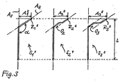
- a first variant of the embodiment of the invention is schematically outlined by the provision of different CCD angles ⁇ 1 , ⁇ 2 and ⁇ 3 in the prosthesis shafts S 1 ', S 2 ' and S 3 'one (here three-part ) Hip joint endoprosthesis system is characterized.
- CCD angle between the shaft longitudinal axis A S and the neck axis A H is achieved that, despite different distances A 1 ', A 2 ', A 3 'between the shaft longitudinal axis A S and the respective reference point R 1 ', R 2 ' , R 3 'all prosthesis shafts have the same total length I.
- an alternative embodiment of the invention is based on three respectively Prosthetic S 1 very schematically illustrated, "S 2" shown or S 3 ".
- the special feature of this embodiment resides in providing an offset O 2 or O 3 in the course of In the case of the prosthesis shafts S 2 “and S 3 ", this offset ensures that, despite different distances between the reference points R 1 ", R 2 “ or R 3 "and the shaft longitudinal axis A s and uniform angle ⁇ between this and the neck axis A H a uniform overall length I can be realized for all prosthesis shafts of the system.
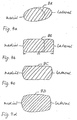
- FIGS. 4a to 4d A few preferred embodiments of the prosthesis neck 9.1 'or 9.2' of a hip joint prosthesis stem are shown in cross-section in FIGS. 4a to 4d, merely to be understood as examples of a large number of possible concrete cross-sectional shapes. To distinguish them from each other, the prosthesis necks in these figures are designated 9A, 9B, 9C and 9D, respectively.
- the anterior-posterior flattening results in an elliptical cross-section, wherein the large axis of the ellipse runs essentially in the mediat-lateral direction.
- 4b shows another variant in which the neck of the prosthesis has the cross-section of a rectangle rounded off in the corner regions. The longer rectangular side a extends here - analogous to the major axis of the ellipse according to FIG. 4 a - in the medial-lateral direction.
- the anterior and posterior boundaries of the cross-sectional shape are straight lines, while the medial and lateral boundary lines are each arcuate sections.
- the prosthesis neck 9D shown in FIG. 4d has a cross-sectional shape in which all the boundary lines are circular arc sections, the circular arcs forming the anterior and posterior boundaries having a larger radius than the arcs forming the medial boundary.
- the outer contour of the corresponding prosthesis neck 9A or 9B is shown proximal to an offset point, as it exists in prosthesis stems of the system sketched in FIG. 3, each with a dashed line.
- the neck cross section in the area proximal to the offset portion will vary from the distal portion of this portion, advantageously allowing a uniform outer contour of the stem in the area of the medial arch despite a lesser or lesser offset in individual prostheses of the system.
- the cross-section of the anchoring portion of the prosthesis stems may, in the embodiments proposed here, have the forms known in the case of leaf-like prosthesis stems;
- the proposed solution is particularly advantageous executable with a substantially trapezoidal shank cross-section, which is particularly well adapted to the anatomical conditions.
- the shape of this trapezium is preferably substantially symmetrical, with the anterior and posterior side edges being the same length and longer than the lateral and medial side edges, of which the medial side edge is the shorter.
- bevels or facets are preferably provided in the edge regions of the corresponding anchoring section.
Abstract
Description
Die Erfindung betrifft ein Hüftgelenk-Endoprothesensystem nach dem Oberbegriff des Anspruches 1.The invention relates to a hip joint Endoprothesensystem according to the preamble of
Hüftgelenk-Endoprothesen mit einem blattartigen Schaft sind aus der EP 0 032 165 B1 bekannt.Hip joint endoprostheses with a leaf-like shaft are known from EP 0 032 165 B1.
Bei dieser bekannten Konstruktion erweitert sich der Schaft vom distalen Ende aus in Richtung seiner Längsachse bis in einen Bereich zwischen etwa 2/3 und 3/4 der Schaftlänge - gemessen entlang der Längsachse - etwa allseitig konisch. Die mediale Schmalseite des Schaftes geht aus dem Konus heraus in einen stetig gekrümmten Bogen über, der an einem kragenartigen Ansatz endet. Dieser Ansatz trennt einen Femur-Verankerungsabschnitt des Schaftes von einem Prothesenhals, der einen sich nach proximal konisch verjüngenden Zapfen umfaßt, welcher zur Aufnahme eines kugelförmigen Gelenkkopfes dient. Die Prothesenhalsachse schneidet die Längsachse des Schaftes unter einem Winkel, der im wesentlichen dem Winkel zwischen dem Schenkelhals und der Femurachse eines natürlichen Hüftgelenkes entspricht.In this known construction, the shaft extends from the distal end in the direction of its longitudinal axis to a range between about 2/3 and 3/4 of the shaft length - measured along the longitudinal axis - approximately conically on all sides. The medial narrow side of the shaft goes from the cone out into a continuously curved arc that ends in a collar-like approach. This approach separates a femoral anchoring portion of the stem from a neck of the prosthesis which includes a proximally conically tapering pin which serves to receive a spherical condyle. The neck of the prosthesis intersects the longitudinal axis of the shaft at an angle substantially equal to the angle between the femoral neck and the femoral axis of a natural hip joint.
Die bekannte Konstruktion hat sich bewährt, um eine sogenannte "Schlußrotation" beim Einsetzen der Prothese zu vermeiden, ohne die Resektionsebene am Schenkelhals zu tief ansetzen zu müssen. Diese nachteilige "Schlußrotation" besteht darin, daß es beim vollständigen Einsetzen der konventionellen Prothesenschäfte wegen der erforderlichen Mindestdicke des Schaftblattes häufig zu einer Rotation des Schaftes im Femurknochen kommt, da infolge der mehrfachen Krümmungen des proximalen Femurendes ein gerader oder auch leicht gebogener Gegenstand von der Wand des Oberschenkelknochens abgelenkt wird.The known construction has proven itself to avoid a so-called "final rotation" when inserting the prosthesis, without having to set the resection level on the femoral neck too low. This adverse "final rotation" is that it often comes at the onset of conventional prosthetic shafts because of the required minimum thickness of the shaft blade to a rotation of the shaft in the femur, since due to the multiple curvatures of the proximal Femurendes a straight or slightly curved object from the wall of the femur is distracted.
In der klinischen Praxis hat sich gezeigt, daß für große Patientengruppen, die ein künstliches Hüftgelenk benötigen, zwar jeweils die Gesamtlänge - verstanden als Projektion der Gesamterstreckung des Prothesenschaftes von dessen distalem Ende bis zum äußersten Ende des am Prothesenhals angeformten Zapfens - im wesentlichen gleich ist, jedoch aufgrund der individuellen anatomischen Besonderheiten gleichwohl Prothesenschäfte mit unterschiedlichen Abmessungen benötigt werden, deren Einsatz auch unterschiedliche Werkzeuge zur Präparation des Femurs erfordert. Genauere Untersuchungen haben ergeben, daß innerhalb solcher Patientengruppen die anatomischen Unterschiede hauptsächlich in einem Unterschied des Abstandes des Hüftgeienkkugel-Drehpunktes zur Femurlängsachse bestehen.In clinical practice, it has been found that for large groups of patients requiring an artificial hip joint, the total length, understood as a projection of the total extension of the prosthesis shaft from its distal end to the outermost end of the neck formed on the neck of the prosthesis, is substantially the same. However, because of the individual anatomical peculiarities, prosthetic stems of different dimensions are nevertheless required, the use of which also requires different tools for the preparation of the femur. More detailed studies have shown that within such groups of patients, the anatomical differences mainly consist of a difference in the distance between the Hüftgeienkkugel pivot point to the femur longitudinal axis.
Die Veröffentlichung FR-A-2 429 010 beschreibt ein Hüftgelenk-Endoprothesensystem, bei dem verschiedene Abstände zwischen der Schaft-Längsachse und dem Mittelpunkt der Gelenkkugel dadurch erreicht werden, daß der Prothesenhats in zwei verschiedenen Längen zur Verfügung gestellt wird, und daß die konische Bohrung in der Gelenkkugel in zwei verschiedenen Größen bzw. Tiefen zur Verfügung gestellt wird. Durch Kombination lassen sich vier verschiedene Abstände realisieren (Seite 1, Zeilen 1-18). Durch den gleichbleibenden Winkel zwischen Schaftlängs-achse und Prothesenhals ändert sich hier jedoch gleichzeitig die auf die Schaftlängsachse projizierte Gesamtlänge der Prothese und der Oberschenkelknochen muß je nach gewählter Prothese unterschiedlich ausgefräst werden.
Durch die Publikation, R. Davey und E. Tozakoglou, A Scientific Exhibit At The 1999 AAOS Meeting, Anaheim, Kalifornien, USA, "The Role Of Lateral Offset Stems", ist es bekannt, eine Konstanz der Gesamtlänge des Prothesenschaftes bei unterschiedlich langen Prothesenhälsen dadurch zu erreichen, daß der zwischen der Prothesenhalsachse und der Längsachse des Verankerungsabschnittes eingeschlossene Winkel in Abhängigkeit von der Länge des Prothesenhalses unterschiedlich gewählt wird. Der unterschiedliche Offset des Schaftes wird durch Verkippen des Prothesenhalses erreicht, und zwar derart, daß die auf die Schaftlängsachse projizierte Gesamtlänge der Prothese konstant bleibt. Nachteilig ist jedoch, daß nach dem Kippen der Prothesenhalsachse sich der Schnittpunkt mit der Schaftlängsachse verändert, wodurch der Nullpunkt des lokalen Koordinaten-systems für eine präoperative Planung verlorengeht. Dementsprechend müßte der Arzt beim Einsatz des bekannten Systems bei einem intra-operativen Wechsel des Schafttyps eine Anpassung am Koordinatennullpunkt vornehmen. Diese Fehlerquelle gilt es zu vermeiden.
Ähnlich verhält es sich im übrigen bei der sogenannten "Müller-Geradschaftprothese". Es wird diesbezüglich auf die Prospekte der Firma Protek Ltd., 3001 Bern, Schweiz, aus den Jahren 1981, 1982 und 1983 jeweils mit dem Titel "Original M.E. Müller Straight Stem Total Hip Replacernent System" verwiesen, wo vorgeschlagen ist, die Prothesenhalsachse in toto parallel zu verschieben. Dadurch ändert sich zwangsläufig auch der Schnittpunkt zwischen Prothesenhalsachse und Schaftlängsachse.The publication FR-A-2 429 010 describes a hip joint endoprosthesis system in which various distances between the shaft longitudinal axis and the center of the ball joint are achieved by providing the prosthesis hatch in two different lengths, and in that the conical bore in the joint ball in two different sizes or depths is provided. By combining four different distances can be realized (
Through the publication, R. Davey and E. Tozakoglou, A Scientific Exhibit At The 1999 AAOS Meeting, Anaheim, Calif., USA, "The Role Of Lateral Offset Stems", it is known to maintain the overall length of the prosthesis stem in prosthesis necks of different lengths to be achieved in that the included between the prosthesis neck axis and the longitudinal axis of the anchoring portion angle is selected differently depending on the length of the prosthesis neck. The different offset of the shaft is achieved by tilting the neck of the prosthesis, in such a way that the total length of the prosthesis projected onto the shaft longitudinal axis remains constant. The disadvantage, however, is that after the tilting of the prosthesis neck axis, the intersection with the shaft longitudinal axis changes, whereby the zero point of the local coordinate system is lost for preoperative planning. Accordingly, the physician would have to make an adjustment to the coordinate zero point when using the known system in an intra-operative change of the shaft type. This source of error should be avoided.
The situation is similar with the so-called "Müller Straight Denture". Reference is made in this regard to the brochures of the company Protek Ltd., 3001 Bern, Switzerland, from the years 1981, 1982 and 1983, each with the title "Original ME Müller Straight Stem Total Hip Replacency System", where it is proposed that the prosthesis neck axis in toto to move in parallel. As a result, the point of intersection between the neck axis of the prosthesis and the shaft longitudinal axis inevitably also changes.
Auf den oben genannten Erkenntnissen beruht die nachfolgend genannte Aufgabenstellung.The above-mentioned findings are based on the following task.
Der Erfindung liegt die Aufgabe zugrunde, ein gattungsgemäßes Hüftgelenk-Endoprothesensystem anzugeben, das eine Zeit- und Kostenersparnis beim Einsatz, insbesondere bei den Vorbereitungsarbalten für die Implantation des Prothesenschaftes, erbringt, und bei dem bei einem intra-operativem Wechsel des Schafttyps keine Anpassung am lokalen Koordinaten-Nullpunkt vorgenommen werden muß.The invention has for its object to provide a generic hip joint Endoprothesystem that provides a time and cost savings in use, especially in the preparatory aries for the implantation of the prosthesis stem, and in the case of an intra-operative change of the shaft type no adaptation to the local Coordinate zero must be made.
Diese Aufgabe wird durch ein Hüftgelenk-Endoprothesensystem mit den Merkmalen des Anspruchs 1 gelöst.This object is achieved by a hip joint Endoprothesensystem with the features of
Die Erfindung schließt den wesentlichen Gedanken ein, ein Hüftgelenk-Endoprothesensystem mit - bezogen auf die Längsachse des Prothesenschaftes - im wesentlichen konstanter Länge anzugeben. Dieses System hat den wesentlichen Vorteil, daß bei der Vorbereitung des Femurs für die Implantation mit einem einheitlichen Raspelmaß für alle Prothesengrößen des Systems gearbeitet werden kann.The invention includes the essential idea to provide a hip joint Endoprothesensystem with - relative to the longitudinal axis of the prosthesis shaft - substantially constant length. This system has the significant advantage that in preparation of the femur for implantation, a uniform rasp size can be used for all prosthesis sizes of the system.
Weiter schließt die Erfindung den Gedanken ein, diese Konstanz der Gesamtlänge des Prothesenschaftes bei unterschiedlich langen Prothesenhälsen in einer Variante dadurch zu erreichen, daß der zwischen der Prothesenhalsachse und der Längsachse des Verankerungsabschnittes eingeschlossene Winkel in Abhängigkeit von der Länge des Prothesenhalses unterschiedlich gewählt wird. In einer anderen Variante wird dieser Winkel (der sogenannte "CCD-Winkel") konstant gehalten, jedoch in den Längsverlauf des Prothesenhalses ein Versatz-Abschnitt ("Offset") eingefügt, wobei der Betrag des vorzusehenden seitlichen Versatzes in Abhängigkeit von der benötigten Prothesenhalslängerespektive in Abhängigkeit vom zu realisierenden Abstand zwischen der Längsachse des Verankerungsabschnittes und demjenigen Punkt ("Referenzpunkt") im Bereich des Prothesenhalszapfens bestimmt wird, der den Mittelpunkt bzw. Drehpunkt der später aufgesetzten Gelenkkugel angibt. Grundsätzlich ist auch eine Kombination beider Varianten möglich.Furthermore, the invention includes the idea of achieving this constancy of the overall length of the prosthesis socket in prosthesis necks of different lengths in a variant in that the angle included between the prosthesis neck axis and the longitudinal axis of the anchoring section is selected differently depending on the length of the neck of the prosthesis. In another variant, this angle (the so-called "CCD angle") is kept constant, but in the longitudinal course of the neck of the prosthesis, an offset portion ("offset") inserted, the amount of lateral offset to be provided depending on the required Prothesenhalslängerespektive in Depending on the distance to be realized between the longitudinal axis of the anchoring portion and that point ("reference point") in the region of the prosthesis neck pin is determined, indicating the center or pivot point of the later attached joint ball. Basically, a combination of both variants is possible.
Die zweite Variante ist eher bei größeren Prothesenhalslängen sinnvoll, für die sich zur Gewährleistung der einheitlichen Gesamtlänge der Prothesenschäfte innerhalb des Systems ein unvorteilhaft kleiner Prothesenhalswinkel ergeben könnte. In solchen Fällen wiegen die mit dem Prothesenhals-Offsetabschnitt erreichbaren Vorteile die möglichen Nachteile der mit dem Einführen des Offset verbundenen Irregularität (eines "Knickes") in der medialen Bogenlinie (die unter Umständen zu hoch belasteten Druckstellen im entsprechenden Bereich der Spongiosa führen kann) wieder auf. Im Bereich nicht allzu langer Prothesenhälse erscheint jedoch aus derzeitiger Sicht die Anpassung des CCD-Winkels an die Prothesenhalslänge als bevorzugte Variante.The second variant is more appropriate for larger prosthesis neck lengths, for which an unfavorably small prosthesis neck angle could result in ensuring the uniform overall length of the prosthesis stems within the system. In such cases, the advantages achievable with the prosthesis neck offset portion may reflect the potential disadvantages of the irregularity associated with the introduction of the offset (a "kink") in the medial arch line (which can potentially lead to high pressure points in the corresponding cancellous bone area) on. In the area of not too long prosthesis necks, however, from the current point of view the adaptation of the CCD angle to the prosthesis neck length as a preferred variant.
Ein weiterer wesentlicher Aspekt besteht in einer im Querschnitt abgeflachten Ausbildung des Prothesenhalses. Dessen Querschnittsgestalt wird dabei bis zu einem gewissen Grade an den blattartigen Querschnitts des Femur-Verankerungsabschnitts angeglichen; das Spektrum umfaßt mehr oder minder flache Ellipsen, in den Eckbereichen abgerundete Rechtecke, Kombinationen aus Kreisabschnitten und Geraden o. ä.. Speziell in Verbindung mit der oben erwähnten Variante eines Prothesenschaftes mit einem Versatz im Längsverlauf des Prothesenhalses ist in speziellen Ausführungen eine sich im Längsverlauf des Halses ändernde Querschnittsgestalt von Vorteil. So kann ein im Bereich des medialen Bogens zunächst elliptischer Querschnitt proximal des Versatzabschnittes kreisförmig werden, oder der Querschnitt der Ellipse kann sich ändern. In einer anderen Ausführung kann der Halsquerschnitt distal vom Achsenversatzpunkt annähernd rechteckig sein, während er proximal dieses Punktes quadratisch ist oder eine veränderte Rechteckform aufweist.Another essential aspect consists in a flattened in cross-section training of the neck of the prosthesis. Its cross-sectional shape is thereby adjusted to a certain degree on the leaf-like cross-section of the femur anchoring section; the spectrum comprises more or less flat ellipses, rounded corners in the corners, combinations of circular sections and straight lines o. Ä .. Especially in connection with the above-mentioned variant of a prosthesis stem with an offset in the longitudinal course of the neck of the prosthesis is in special embodiments in a longitudinal course the neck-changing cross-sectional shape of advantage. Thus, in the area of the medial arch, initially an elliptical cross section can become circular proximal to the offset section, or the cross section of the ellipse can change. In another embodiment, the neck cross-section may be approximately rectangular distal to the axis offset point, while it is square proximal to that point or has a modified rectangular shape.
In einer speziellen, vorteilhaft an die anatomischen Verhältnisse angepaßten Ausführung hat der Schaftquerschnitt mindestens im proximalen Bereich annähernd eine Trapezform, insbesondere eine symmetrische Trapezform mit zwei gleich langen längeren Seitenkanten, die im Querschnitt die anterior bzw. posterior gelegenen Seitenflächen des Schaftes begrenzen, und zwei unterschiedlich langen kürzeren Seitenkanten, von denen die kürzere der medialen Stimfläche und die längere der lateralen Stirnfläche des Schaftes entspricht.In a special embodiment, which is advantageously adapted to the anatomical conditions, the shaft cross-section has approximately a trapezoidal shape, in particular a symmetrical trapezoidal shape with two equally long longer side edges defining in cross-section the anterior and posterior side surfaces of the shaft, and two different long shorter side edges, of which the shorter corresponds to the medial end face and the longer of the lateral end face of the shaft.
Weitere vorteilhafte konstruktive Maßnahmen und Alternativen der erfindungsgemäßen Konstruktion sind in den Unteransprüchen sowie den folgenden Ausführungsbeispielen anhand derbeigefügten Zeichnungen näher erläutert. Diese zeigen in
- Fig. 1
- eine Seitenansicht einerblattartigen Schaftprothese entsprechend dem Stand der Technik, in die skizzenartig mögliche Lagen verschiedener Gelenkkugeln bei unterschiedlich langen Halsabschnitten mit den entsprechenden Referenzpunkten sowie Abständen zur Schaftlängsachse eingetragen sind,
- Fig. 2
- eine schematische Darstellung zur Erläuterung einer ersten Ausführungsform der Erfindung,
- Fig. 3
- eine schematische Darstellung zur Erläuterung einer zweiten Ausführungsform, und
- Fig. 4a - 4d
- skizzenartige Darstellungen verschiedener Prothesenhalsquerschnitte.
- Fig. 1
- a side view of a sheet-like shaft prosthesis according to the prior art, are entered in the sketch-like possible layers of different joint balls at different lengths neck sections with the corresponding reference points and distances to the shaft longitudinal axis,
- Fig. 2
- a schematic representation for explaining a first embodiment of the invention,
- Fig. 3
- a schematic representation for explaining a second embodiment, and
- Fig. 4a - 4d
- sketch-like representations of different prosthesis neck cross sections.
Ein in Fig. 1 dargestellter Prothesenschaft 1 dient zur Verankerung einer Hüftgelenkprothese im Femur. Ausgehend von einem distalen Ende 5, erweitert sich der Prothesenschaft 1 nach proximal allseitig etwa gleichmäßig und geht in einem medialen Bogen 7 in einen Prothesenhals 9 über, der proximal in einem Zapfen 11 zur Aufnahme einer Gelenkkugel endet. Die Lage eines Verankerungsabschnittes 3 des Prothesenschaftes 1 ist durch eine Schaftlängsachse AS beschreibbar, während die Lage des Prothesenhalses durch dessen Längsachse AH beschreibbar ist. Die Schaftlängsachse AS und die Halsachse AH schließen einen Winkel ∝ (üblicherweise bezeichnet als CCD-Winkel) miteinander ein. In Fig. 1 ist weiterhin die bei der Implantation zu beachtende Resektionsebene RES angegeben.A
Wie in der Figur skizzenartig angedeutet, können verschiedene Prothesenschäfte der in der Figur gezeigten Art in einem Schaftsystem unterschiedliche Halslängen und damit - bei als konstant vorausgesetztem CCD-winkel ∝ - unterschiedliche Abstände A1, A2, A3 zwischen der Schaftlängsachse AS und einem jeweils zugehörigen Referenzpunkt R1, R2, R3 im Bereich des jeweiligen Zapfens 11 haben. Die Referenzpunkte R1, R2, R3 bezeichnen jeweils den Mittelpunkt einer zugehörigen Gelenkkugel (die in der Figur kein gesondertes Bezugszeichen hat). Auch die Gesamtlängen der einzelnen Prothesen des Systems bzw. die Abstände zwischen dem distalen Ende 5 und dem jeweiligen Referenzpunkt R1, R2 bzw. R3 - in der Figur bezeichnet mit I1, I2 und I3 - sind unterschiedlich. Dies bedingt bei Präparation des Femurs unterschiedliche Raspelmaße und damit, bezogen auf eine größere Patientenanzahl, einen relativ hohen präparativen Aufwand.As indicated sketch-like in the figure, different prosthesis stems of the type shown in the figure in a shaft system different neck lengths and thus - at as constant assuming CCD angle α - different distances A 1 , A 2 , A 3 between the shaft longitudinal axis A S and a each associated reference point R 1 , R 2 , R 3 in the region of the
In Fig. 2 ist schematisch eine erste Variante der Ausführung der Erfindung skizziert, die durch das Vorsehen unterschiedlicher CCD-Winkel ∝1, ∝2 bzw. ∝3 bei den Prothesenschäften S1', S2' und S3' eines (hier dreiteiligen) Hüftgelenk-Endoprothesensystems charakterisiert ist. Durch Variation des CCD-Winkels zwischen der Schaftlängsachse AS und der Halsachse AH wird erreicht, daß trotz unterschiedlicher Abstände A1', A2', A3' zwischen der Schaftlängsachse AS und dem jeweiligen Referenzpunkt R1', R2', R3' alle Prothesenschäfte die gleiche Gesamtlänge I haben.In Fig. 2, a first variant of the embodiment of the invention is schematically outlined by the provision of different CCD angles α 1 , α 2 and α 3 in the prosthesis shafts S 1 ', S 2 ' and S 3 'one (here three-part ) Hip joint endoprosthesis system is characterized. By varying the CCD angle between the shaft longitudinal axis A S and the neck axis A H is achieved that, despite different distances A 1 ', A 2 ', A 3 'between the shaft longitudinal axis A S and the respective reference point R 1 ', R 2 ' , R 3 'all prosthesis shafts have the same total length I.
In Fig. 3 ist eine alternative Ausführung der Erfindung anhand von drei jeweils grob schematisch dargestellten Prothesenschäften S1", S2" bzw. S3" dargestellt. Die Besonderheit dieser Ausführung besteht im Vorsehen eines Versatzes O2 bzw. O3 im Verlauf des Prothesenhalses bei den Prothesenschäften S2" und S3". Durch diesen Versatz (Offset) wird erreicht, daß trotz unterschiedlicher Abstände zwischen den Referenzpunkten R1", R2" bzw. R3'' und der Schaftlängsachse AS und einheitlichem Winkel ∝ zwischen dieser und der Halsachse AH eine einheitliche Gesamtlänge I für alle Prothesenschäfte des Systems realisiert werden kann.In Fig. 3, an alternative embodiment of the invention is based on three respectively Prosthetic S 1 very schematically illustrated, "S 2" shown or S 3 ". The special feature of this embodiment resides in providing an offset O 2 or O 3 in the course of In the case of the prosthesis shafts S 2 "and S 3 ", this offset ensures that, despite different distances between the reference points R 1 ", R 2 " or R 3 "and the shaft longitudinal axis A s and uniform angle α between this and the neck axis A H a uniform overall length I can be realized for all prosthesis shafts of the system.
In Fig. 4a bis 4d sind - lediglich als Beispiele für eine Vielzahl möglicher konkreter Querschnittsformen zu verstehen - einige bevorzugte Ausführungen des Prothesenhalses 9.1' bzw. 9.2' eines Hüftgelenk-Prothesenschaftes im Querschnitt gezeigt. Zur Unterscheidung voneinander sind die Prothesenhälse in diesen Figuren mit 9A, 9B, 9C bzw. 9D bezeichnet.A few preferred embodiments of the prosthesis neck 9.1 'or 9.2' of a hip joint prosthesis stem are shown in cross-section in FIGS. 4a to 4d, merely to be understood as examples of a large number of possible concrete cross-sectional shapes. To distinguish them from each other, the prosthesis necks in these figures are designated 9A, 9B, 9C and 9D, respectively.
Bei der Ausführung nach Fig. 4a ergibt die anterior-posteriore Abflachung einen elliptischen Querschnitt, wobei die große Achse der Ellipse im wesentlichen in mediat-lateraler Richtung verläuft. Fig. 4b zeigt eine andere Variante, bei der der Prothesenhals den Querschnitt eines in den Eckbereichen abgerundeteten Rechtecks hat. Die längere Rechtecksseite a erstreckt sich hier - analog zur großen Achse der Ellipse nach Fig. 4a - in medial-lateraler Richtung. Bei der in Fig. 4c gezeigten Ausführung sind die anteriore und posteriore Begrenzung der Querschnittsform Geraden, während die mediale und laterale Begrenzungslinie jeweils Kreisbogenabschnitte sind. Der in Fig. 4d gezeigte Prothesenhals 9D hat eine Querschnittsform, bei der alle Begrenzungslinien Kreisbogenabschnitte sind, wobei die die anteriore und posteriore Begrenzung bildenden Kreisbögen einen größeren Radius als die die mediale Begrenzung bildenden Kreisbögen haben.In the embodiment according to FIG. 4 a, the anterior-posterior flattening results in an elliptical cross-section, wherein the large axis of the ellipse runs essentially in the mediat-lateral direction. 4b shows another variant in which the neck of the prosthesis has the cross-section of a rectangle rounded off in the corner regions. The longer rectangular side a extends here - analogous to the major axis of the ellipse according to FIG. 4 a - in the medial-lateral direction. In the embodiment shown in Fig. 4c, the anterior and posterior boundaries of the cross-sectional shape are straight lines, while the medial and lateral boundary lines are each arcuate sections. The
In Fig.4a und 4b ist jeweils mit einer gestrichelten Linie die Außenkonturdes entsprechenden Prothesenhalses 9A bzw. 9B proximal eines Versatz-Punktes gezeigt, wie er bei Prothesenschäften des in Fig. 3 skizzierten Systems existiert. Bei einersolchen Ausführung variiertalso der Halsquerschnitt in dem Bereich proximal des Versatzabschnittes gegenüber dem Bereich distal dieses Abschnittes, was in vorteilhafter Weise eine einheitliche Außenkontur des Schaftes im Bereich des medialen Bogens trotz eines mehroder weniger großen Offset bei einzelnen Prothesen des Systems möglich machen kann.4a and 4b, the outer contour of the
Der Querschnitt des Verankerungsabschnitts der Prothesenschäfte kann bei den hier vorgeschlagenen Ausführungen die bei blattartigen Prothesenschäften bekannten Formen haben; besonders vorteilhaft ausführbar ist die vorgeschlagene Lösung aber mit einem im wesentlichen trapezförmigen Schaftquerschnitt, der besonders gut an die anatomischen Gegebenheiten angepaßt ist. Die Gestalt dieses Trapezes ist bevorzugt im wesentlichen symmetrisch, wobei die anteriore und posteriore Seitenkante gleich lang und länger als die laterale und die mediale Seitenkante sind, von denen wiederum die mediale Seitenkante die kürzere ist. In den Kantenbereichen des entsprechenden Verankerungsabschnittes (d. h. an den Ecken des die Querschnittsgestalt bestimmenden Trapezes) sind bevorzugt Fasen bzw. Facetten vorgesehen.The cross-section of the anchoring portion of the prosthesis stems may, in the embodiments proposed here, have the forms known in the case of leaf-like prosthesis stems; However, the proposed solution is particularly advantageous executable with a substantially trapezoidal shank cross-section, which is particularly well adapted to the anatomical conditions. The shape of this trapezium is preferably substantially symmetrical, with the anterior and posterior side edges being the same length and longer than the lateral and medial side edges, of which the medial side edge is the shorter. In the edge regions of the corresponding anchoring section (i.e., at the corners of the trapezoid defining the cross-sectional shape), bevels or facets are preferably provided.
Sämtliche in den Anmetdungsunterlagen offenbarten Merkmale werden als erfindungswesentlich beansprucht, soweit sie einzeln oder in Kombination gegenüber dem Stand der Technik neu sind.All features disclosed in the application documents are claimed as essential to the invention, as far as they are new individually or in combination with respect to the prior art.
- 1; 1.1', 1.2'1; 1.1 ', 1.2'
- Prothesenschaftprosthetic socket
- 3; 3.1', 3.2'3; 3.1 ', 3.2'
- Verankerungsabschnittanchoring section
- 55
- distales Endedistal end
- 77
- medialer Bogenmedial bow
- 9, 9A, 9B, 9C, 9D9, 9A, 9B, 9C, 9D
- Prothesenhalsprosthesis neck
- 1111
- Zapfenspigot
- AS A S
- Schaftlängsachselong shaft axis
- AH A H
- Halsachseneck axis
- A1, A2, A3; A1',A2',A3'; A1", A2", A3"A 1 , A 2 , A 3 ; A 1 ', A 2 ', A 3 '; A 1 ", A 2 ", A 3 "
- Abstand zwischen Schaftlängsachse und ReferenzpunktDistance between shaft longitudinal axis and reference point
- I, I1, I2, I3 I, I 1 , I 2 , I 3
- Schaftlängeshaft length
- R1, R2, R3; R1', R2', R3'; R1", R2", R3"R 1 , R 2 , R 3 ; R 1 ', R 2 ', R 3 '; R 1 ", R 2 ", R 3 "
- Referenzpunktreference point
- RESRES
- Resektionsebeneresection
- S1', S2', S3'; S1", S2", S3 "S 1 ', S 2 ', S 3 '; S 1 ", S 2 ", S 3 "
- Prothesenschaftprosthetic socket
- ∝, ∝1, ∝2, ∝3 Α, α 1 , α 2 , α 3
- CCD-WinkelCCD angle
Claims (7)
- A hip joint endoprosthesis system comprising a plurality of, in particular blade-type, prosthesis shafts (1.1', 1.2'; S1', S2', S3'; S1", S2", S3") for anchorage in the femur, wherein each shaft widens from a distal end (5) in a proximal direction substantially on all sides and has an anchoring portion having a longitudinal shaft axis (As) and merging medially into a curve (7.1', 7.2') which continues into a prosthesis neck (9.1', 9.2') having a prosthesis neck axis (AH), wherein a reference point distance (A1', A2', A3'; A1", A2"; A2"') between the longitudinal shaft axis and a reference point (R1', R2', R3'; R1", R2", R3") on the prosthesis neck axis designates the position of the centre point of a ball attached to the prosthesis neck and varies in the prosthesis shafts, characterised in that, with an unchanged point of intersection between the longitudinal shaft axis (AS) and the prosthesis neck axis (AH), the length (L) of the projection onto the longitudinal shaft axis (AS) of the overall extent of the prosthesis shaft from the distal end of the anchoring portion to the reference point or the proximal end of the prosthesis neck is the same in all prosthesis shafts.
- A hip joint endoprosthesis system according to claim 1, characterised in that, in the prosthesis shafts (S1', S2', S3'; 1.1', 1.2') with different reference point distances (A1', A2', A3'), a prosthesis neck angle (α1, α2, α3; α'1.1, α'1.2) between the longitudinal shaft axis (AS) and the prosthesis neck axis (AH) is varyingly determined as a function of the reference point distance.
- A hip joint endoprosthesis system according to claim 1 or 2, characterised in that, in at least one of the prosthesis shafts (S1", S2", S3") with different reference point distances (A1", A2", A3"), an axial offset (O1, O2) is provided in the longitudinal extent of the prosthesis neck in a distal direction and its size is determined as a function of the reference point distance.
- A hip joint endoprosthesis system according to any one of the preceding claims, characterised in that the maximum extent of the prosthesis neck (9.1', 9.2'; 9A-9D) transversely to the prosthesis neck axis (AH) in the anterior-posterior direction is smaller at least over a portion of its length than the maximum extent in the medial-lateral direction.
- A hip joint endoprosthesis system according to claim 4, characterised in that the cross-section of the prosthesis neck (9.1', 9.2'; 9A-9D) is substantially elliptical or rectangular at least over a portion of its extent or has at least one straight and one curved boundary line.
- A hip joint endoprosthesis system according to claim 3 and claim 4 or 5, characterised in that the cross-section of the prosthesis neck (9A, 9B) in a region distally of the axial offset point is formed differently from the cross-section in a region proximally of the axial offset point.
- A hip joint endoprosthesis system according to any one of the preceding claims, characterised in that the path of a medial curve (7.1', 7.2') connecting the anchoring portion (3.1', 3.3') to the prosthesis neck (9.1', 9.2') is identical in all prosthesis shafts (1.1', 1.2') at least over the greatest part of their length.
Applications Claiming Priority (3)
| Application Number | Priority Date | Filing Date | Title |
|---|---|---|---|
| DE19928709A DE19928709B4 (en) | 1999-06-23 | 1999-06-23 | Hip endoprosthesis |
| DE19928709 | 1999-06-23 | ||
| US09/599,663 US6436147B1 (en) | 1999-06-23 | 2000-06-22 | Hip-joint endoprosthesis system |
Publications (5)
| Publication Number | Publication Date |
|---|---|
| EP1062923A2 EP1062923A2 (en) | 2000-12-27 |
| EP1062923A3 EP1062923A3 (en) | 2002-10-16 |
| EP1062923B1 EP1062923B1 (en) | 2004-01-14 |
| EP1062923B2 EP1062923B2 (en) | 2006-04-19 |
| EP1062923B9 true EP1062923B9 (en) | 2006-07-05 |
Family
ID=26053895
Family Applications (1)
| Application Number | Title | Priority Date | Filing Date |
|---|---|---|---|
| EP00112385A Expired - Lifetime EP1062923B9 (en) | 1999-06-23 | 2000-06-09 | Hip joint endoprostheses system |
Country Status (5)
| Country | Link |
|---|---|
| US (1) | US6436147B1 (en) |
| EP (1) | EP1062923B9 (en) |
| AT (1) | ATE257683T1 (en) |
| DE (3) | DE19928709B4 (en) |
| ES (1) | ES2214194T5 (en) |
Cited By (10)
| Publication number | Priority date | Publication date | Assignee | Title |
|---|---|---|---|---|
| US7678150B2 (en) | 2004-06-15 | 2010-03-16 | Tornier Sas | Total shoulder prosthesis of an inverted type |
| US7887544B2 (en) | 2003-03-10 | 2011-02-15 | Tornier Sas | Ancillary tool for positioning a glenoid implant |
| US8080063B2 (en) | 2006-04-13 | 2011-12-20 | Tornier Sas | Glenoid component with an anatomically optimized keel |
| US8277511B2 (en) | 2006-04-21 | 2012-10-02 | Tornier Sas | Shoulder or hip prosthesis and method for setting same |
| US8303665B2 (en) | 2004-06-15 | 2012-11-06 | Tornier Sas | Glenoidal component, set of such components and shoulder prosthesis incorporating such a glenoidal component |
| US8864834B2 (en) | 2007-01-30 | 2014-10-21 | Tornier Sas | Method and apparatus for fitting a shoulder prosthesis |
| US8974536B2 (en) | 2007-01-30 | 2015-03-10 | Tornier Sas | Intra-articular joint replacement |
| US9433507B2 (en) | 2006-03-21 | 2016-09-06 | Tornier, Inc. | Non-spherical articulating surfaces in shoulder and hip replacement |
| US9474619B2 (en) | 2006-03-21 | 2016-10-25 | Tornier, Inc. | Glenoid component with improved fixation stability |
| US10631993B2 (en) | 2010-10-22 | 2020-04-28 | Tornier, Inc. | Set of glenoid components for a shoulder prosthesis |
Families Citing this family (34)
| Publication number | Priority date | Publication date | Assignee | Title |
|---|---|---|---|---|
| US6200350B1 (en) * | 1999-10-01 | 2001-03-13 | Medidea, Llc | Anti-impingement femoral prostheses |
| US6986792B2 (en) * | 2002-09-13 | 2006-01-17 | Smith & Nephew, Inc. | Prostheses |
| FR2844994B1 (en) * | 2002-09-27 | 2005-06-24 | Medacta Int Sa | ANATOMIC FEMORAL IMPLANT FOR HIP PROSTHESIS |
| FR2858761B1 (en) * | 2003-08-14 | 2005-11-11 | Philippe Lapresle | TOGETHER FOR THE FORMATION OF THE FEMALE PART OF A TOTAL HIP PROSTHESIS AND TOGETHER FOR TOTAL HIP PROSTHESIS |
| ATE349980T1 (en) * | 2003-11-07 | 2007-01-15 | Bone And Joint Res S A | DEVICE FOR REPLACING THE HIP JOINT |
| US7060102B2 (en) * | 2004-01-21 | 2006-06-13 | Thompson Matthew T | Femoral implant for hip arthroplasty |
| DE102004008138B8 (en) * | 2004-02-19 | 2009-04-23 | Mathys Ag Bettlach | Femoral component for a hip joint endoprosthesis |
| FR2871368B1 (en) * | 2004-06-15 | 2006-08-25 | Tornier Sas | SET OF HUMERAL COMPONENTS FOR TOTAL SHOULDER PROSTHESIS |
| DE102004051492B3 (en) * | 2004-10-21 | 2006-05-18 | Schmitz, Jürgen, Dr.med. | Femur component for a total hip endoprosthesis in which the axes of shaft part and the joint-attachment part intersect at specific angles in two planes at 90 degrees to each other |
| GB2419291A (en) | 2004-10-21 | 2006-04-26 | Biomet Uk Ltd | A femoral head prosthesis |
| FR2878149B1 (en) * | 2004-11-24 | 2012-07-13 | Biegun Jean Francois | SHORT CONE FOR EMBANCING FEMALE HEADS WITH GREAT DEBATMENT |
| AU2006201835B2 (en) * | 2005-05-09 | 2012-08-30 | Smith & Nephew, Inc. | Orthopaedic implants and methods for making the same |
| DE102005048873A1 (en) * | 2005-09-20 | 2007-03-29 | Plus Orthopedics Ag | Leaf-like stem for hip joint prosthesis |
| FR2893837B1 (en) * | 2005-11-28 | 2008-08-08 | Tornier Sas | GAME OF HIP PROSTHESES |
| US20070225821A1 (en) | 2006-03-21 | 2007-09-27 | Axiom Orthopaedics, Inc. | Femoral and humeral stem geometry and implantation method for orthopedic joint reconstruction |
| CA2674288C (en) * | 2007-02-09 | 2015-11-24 | Zimmer, Inc. | Prosthetic hip implants |
| AU2008275015B2 (en) | 2007-07-11 | 2014-08-14 | Smith & Nephew, Inc. | Methods and apparatus for determining pin placement during hip surgery |
| WO2010096124A1 (en) * | 2008-10-29 | 2010-08-26 | Thompson Matthew T | Femoral implant with improved range of joint motion |
| US9408652B2 (en) | 2010-04-27 | 2016-08-09 | Tornier Sas | Intra-articular joint replacement and method |
| EP2579817B1 (en) | 2010-06-08 | 2022-08-31 | Smith & Nephew, Inc. | Implant components and methods |
| EP2704651A4 (en) | 2011-05-03 | 2014-10-08 | Smith & Nephew Inc | Patient-matched guides for orthopedic implants |
| EP2586387A1 (en) | 2011-10-31 | 2013-05-01 | Tornier Orthopedics Ireland Ltd. | Bone reamer |
| CN104105459B (en) | 2011-12-07 | 2018-10-30 | 史密夫和内修有限公司 | The plastic surgery reinforcer of pit with recess |
| JP6282596B2 (en) | 2011-12-07 | 2018-02-21 | スミス アンド ネフュー インコーポレイテッド | Orthopedic implant augment |
| US9427322B1 (en) * | 2012-06-27 | 2016-08-30 | Signal Medical Corporation | Hip implant |
| US10034759B2 (en) | 2012-10-29 | 2018-07-31 | Tornier Orthopedics Ireland Ltd. | Reverse shoulder implants |
| CA2942523A1 (en) * | 2014-03-12 | 2015-09-17 | Encore Medical, L.P. | Femoral hip stem |
| FR3029769A1 (en) | 2014-12-10 | 2016-06-17 | Tornier Sa | KIT FOR A PROSTHESIS OF SHOULDER |
| CA3059036A1 (en) | 2016-04-19 | 2017-10-26 | Imascap Sas | Pre-operatively planned humeral implant and planning method |
| FR3050106B1 (en) * | 2016-04-19 | 2018-04-27 | Hip Hip Hip | RANGE OF LATERALIZED FEMALE PROSTHESES |
| EP4032506B1 (en) | 2016-08-24 | 2023-07-26 | Howmedica Osteonics Corp. | Humeral head implant system |
| EP3600166A1 (en) | 2017-03-31 | 2020-02-05 | Tornier, Inc. | Modular humeral head |
| CA3113978C (en) | 2018-10-02 | 2023-10-24 | Tornier, Inc. | Modular humeral head |
| USD938590S1 (en) | 2019-10-01 | 2021-12-14 | Howmedica Osteonics Corp. | Humeral implant |
Family Cites Families (21)
| Publication number | Priority date | Publication date | Assignee | Title |
|---|---|---|---|---|
| DE32165C (en) | W. E. MIKSCH in Prag | Water level indicator with water wheel and bell | ||
| US4068324A (en) * | 1977-01-19 | 1978-01-17 | Bio-Dynamics Inc. | Platform supported hip prosthesis |
| FR2429010B1 (en) * | 1978-06-20 | 1985-07-12 | Tornier Sa | IMPROVEMENTS ON HIP PROSTHESES |
| CH642252A5 (en) * | 1980-01-14 | 1984-04-13 | Sulzer Ag | LEAFY SHAFT FOR ANCHORING A HIP JOINT PROSTHESIS. |
| GB8332119D0 (en) * | 1983-12-01 | 1984-01-11 | Weightman B O | Endoprosthetic bone joint components |
| FR2574283B1 (en) * | 1984-12-07 | 1989-09-08 | Tornier Sa | PROSTHESIS OF THE FEMUR'S NECK WITH AN Eccentric Ball |
| FR2610824B1 (en) * | 1987-02-12 | 1997-01-24 | Cuilleron J | IMPROVED FEMALE ROD FOR HIP PROSTHESES IMPLANTED WITHOUT CEMENT SEALING |
| US5156627A (en) * | 1987-03-30 | 1992-10-20 | Regents Of The University Of California | Collarless femoral hip prosthesis |
| FR2631543B1 (en) * | 1988-05-20 | 1997-04-04 | Schwartz Claude | PROSTHETIC FEMORAL HEAD WITH VARIABLE SPATIAL ORIENTATION |
| IT1227215B (en) * | 1988-09-23 | 1991-03-27 | Cremascoli Spa G | HIP PROSTHESIS WITHOUT CEMENT, WITH INCREASED RESISTANCE |
| FR2639820B1 (en) * | 1988-12-07 | 1994-09-02 | Implants Instr Ch Fab | FEMALE RODS FOR TOTAL HIP PROSTHESES |
| DE8901018U1 (en) * | 1989-01-31 | 1989-03-16 | Orthoplant Endoprothetik Gmbh, 2800 Bremen, De | |
| FR2666737B1 (en) † | 1990-09-18 | 1992-12-18 | Medinov Sa | HIP PROSTHETIC ASSEMBLY. |
| FR2667785A1 (en) * | 1990-10-16 | 1992-04-17 | Procom | Femoral element for hip prosthesis |
| US5108451A (en) * | 1991-01-31 | 1992-04-28 | Forte Mark R | Femoral component of a hip joint prosthesis |
| DE4227139C2 (en) * | 1992-08-17 | 1994-06-01 | Eska Medical Gmbh & Co | Ball endoprosthesis |
| US5888210A (en) * | 1992-10-12 | 1999-03-30 | Draenert; Klaus | Stem of a femoral component of a hip joint endoprosthesis |
| FR2701835B1 (en) * | 1993-02-22 | 1995-04-28 | Medinov Sa | Femoral stem for hip prosthesis. |
| GB9316749D0 (en) * | 1993-08-12 | 1993-09-29 | Biomet Ltd | Prosthetic hip component |
| FR2753081B1 (en) * | 1996-09-11 | 1999-03-05 | Daniel Noyer | HIP FEMALE PROSTHESIS WITH ANTEPULSED FLANGE |
| US6168632B1 (en) * | 1996-11-29 | 2001-01-02 | Mathys Medizinaltechnik Ag | Femur component of a hip joint endoprosthesis |
-
1999
- 1999-06-23 DE DE19928709A patent/DE19928709B4/en not_active Expired - Lifetime
- 1999-06-23 DE DE29924628U patent/DE29924628U1/en not_active Expired - Lifetime
-
2000
- 2000-06-09 DE DE50005006T patent/DE50005006D1/en not_active Expired - Lifetime
- 2000-06-09 EP EP00112385A patent/EP1062923B9/en not_active Expired - Lifetime
- 2000-06-09 ES ES00112385T patent/ES2214194T5/en not_active Expired - Lifetime
- 2000-06-09 AT AT00112385T patent/ATE257683T1/en active
- 2000-06-22 US US09/599,663 patent/US6436147B1/en not_active Expired - Lifetime
Cited By (15)
| Publication number | Priority date | Publication date | Assignee | Title |
|---|---|---|---|---|
| US7887544B2 (en) | 2003-03-10 | 2011-02-15 | Tornier Sas | Ancillary tool for positioning a glenoid implant |
| US8187282B2 (en) | 2003-03-10 | 2012-05-29 | Tornier Sas | Ancillary tool for positioning a glenoid implant |
| US7678150B2 (en) | 2004-06-15 | 2010-03-16 | Tornier Sas | Total shoulder prosthesis of an inverted type |
| US11523907B2 (en) | 2004-06-15 | 2022-12-13 | Tornier Sas | Glenoidal component, set of such components and shoulder prosthesis incorporating such a glenoidal component |
| US10610363B2 (en) | 2004-06-15 | 2020-04-07 | Tornier Sas | Glenoidal component, set of such components and shoulder prosthesis incorporating such a glenoidal component |
| US8303665B2 (en) | 2004-06-15 | 2012-11-06 | Tornier Sas | Glenoidal component, set of such components and shoulder prosthesis incorporating such a glenoidal component |
| US9545312B2 (en) | 2004-06-15 | 2017-01-17 | Tornier Sas | Glenoidal component, set of such components and shoulder prosthesis incorporating such a glenoidal component |
| US9474619B2 (en) | 2006-03-21 | 2016-10-25 | Tornier, Inc. | Glenoid component with improved fixation stability |
| US9433507B2 (en) | 2006-03-21 | 2016-09-06 | Tornier, Inc. | Non-spherical articulating surfaces in shoulder and hip replacement |
| US8080063B2 (en) | 2006-04-13 | 2011-12-20 | Tornier Sas | Glenoid component with an anatomically optimized keel |
| US8277511B2 (en) | 2006-04-21 | 2012-10-02 | Tornier Sas | Shoulder or hip prosthesis and method for setting same |
| US8974536B2 (en) | 2007-01-30 | 2015-03-10 | Tornier Sas | Intra-articular joint replacement |
| US8864834B2 (en) | 2007-01-30 | 2014-10-21 | Tornier Sas | Method and apparatus for fitting a shoulder prosthesis |
| US10631993B2 (en) | 2010-10-22 | 2020-04-28 | Tornier, Inc. | Set of glenoid components for a shoulder prosthesis |
| US11304815B2 (en) | 2010-10-22 | 2022-04-19 | Howmedica Osteonics Corp. | Set of glenoid components for a shoulder prosthesis |
Also Published As
| Publication number | Publication date |
|---|---|
| EP1062923A2 (en) | 2000-12-27 |
| ES2214194T5 (en) | 2006-12-01 |
| DE19928709A1 (en) | 2001-01-04 |
| ES2214194T3 (en) | 2004-09-16 |
| DE50005006D1 (en) | 2004-02-19 |
| DE19928709B4 (en) | 2005-02-03 |
| EP1062923B2 (en) | 2006-04-19 |
| US6436147B1 (en) | 2002-08-20 |
| DE29924628U1 (en) | 2004-05-06 |
| ATE257683T1 (en) | 2004-01-15 |
| EP1062923B1 (en) | 2004-01-14 |
| EP1062923A3 (en) | 2002-10-16 |
Similar Documents
| Publication | Publication Date | Title |
|---|---|---|
| EP1062923B9 (en) | Hip joint endoprostheses system | |
| EP0680292B1 (en) | System for constructing a knee-joint endoprosthesis | |
| EP0027159B1 (en) | Hip joint prosthesis | |
| EP2022448B1 (en) | Artificial joint and a joint part for this purpose | |
| DE10103482C2 (en) | expandable socket | |
| EP0159462B1 (en) | Femoral part of a total endoprosthesis for a hip joint | |
| EP0085147B1 (en) | Straight flat shaft for a joint endoprosthesis | |
| EP1164978B1 (en) | Flat shaft of a hip joint prosthesis for anchoring in the femur | |
| CH666178A5 (en) | FEMUR HEAD PROSTHESIS. | |
| WO2007054553A1 (en) | Implant | |
| DE19722389C2 (en) | Modular knee arthrodesis implant | |
| WO1998042279A1 (en) | Hip joint endoprosthesis | |
| DE2805305C2 (en) | ||
| EP0163042A1 (en) | Femoral part for a hip joint endoprosthesis | |
| EP0669116A1 (en) | Femoral part for a hip joint endoprosthesis | |
| EP0238860B1 (en) | Femoral part of a endoprosthesis for a hip joint | |
| WO2000064384A1 (en) | Endoprosthesis, especially for an artificial hip joint | |
| DE19547638A1 (en) | Thigh part of a hip joint endoprosthesis | |
| EP0427902A1 (en) | Rectilinear stam for hip joint prosthesis | |
| DE3329978C2 (en) | Upper leg part of a hip joint prosthesis | |
| WO1984003037A1 (en) | Straight sheet-shaped pin for joint endoprosthesis | |
| DE4339895C1 (en) | System for designing a knee-joint endoprosthesis | |
| DE4304022A1 (en) | Femoral part of a hip joint endoprosthesis | |
| DE102004038281B3 (en) | Femoral neck prosthesis for an artificial hip joint comprises an implantable shaft which is curved and has a proximal region with a polygonal cross-section and a distal region with a round cross-section | |
| WO2004069103A1 (en) | Implant |
Legal Events
| Date | Code | Title | Description |
|---|---|---|---|
| PUAI | Public reference made under article 153(3) epc to a published international application that has entered the european phase |
Free format text: ORIGINAL CODE: 0009012 |
|
| AK | Designated contracting states |
Kind code of ref document: A2 Designated state(s): AT BE CH CY DE DK ES FI FR GB GR IE IT LI LU MC NL PT SE |
|
| AX | Request for extension of the european patent |
Free format text: AL;LT;LV;MK;RO;SI |
|
| PUAL | Search report despatched |
Free format text: ORIGINAL CODE: 0009013 |
|
| AK | Designated contracting states |
Kind code of ref document: A3 Designated state(s): AT BE CH CY DE DK ES FI FR GB GR IE IT LI LU MC NL PT SE |
|
| AX | Request for extension of the european patent |
Free format text: AL;LT;LV;MK;RO;SI |
|
| 17P | Request for examination filed |
Effective date: 20021025 |
|
| GRAH | Despatch of communication of intention to grant a patent |
Free format text: ORIGINAL CODE: EPIDOS IGRA |
|
| AKX | Designation fees paid |
Designated state(s): AT BE CH CY DE DK ES FI FR GB GR IE IT LI LU MC NL PT SE |
|
| GRAS | Grant fee paid |
Free format text: ORIGINAL CODE: EPIDOSNIGR3 |
|
| GRAA | (expected) grant |
Free format text: ORIGINAL CODE: 0009210 |
|
| AK | Designated contracting states |
Kind code of ref document: B1 Designated state(s): AT BE CH CY DE DK ES FI FR GB GR IE IT LI LU MC NL PT SE |
|
| PG25 | Lapsed in a contracting state [announced via postgrant information from national office to epo] |
Ref country code: CY Free format text: LAPSE BECAUSE OF FAILURE TO SUBMIT A TRANSLATION OF THE DESCRIPTION OR TO PAY THE FEE WITHIN THE PRESCRIBED TIME-LIMIT Effective date: 20040114 Ref country code: FI Free format text: LAPSE BECAUSE OF FAILURE TO SUBMIT A TRANSLATION OF THE DESCRIPTION OR TO PAY THE FEE WITHIN THE PRESCRIBED TIME-LIMIT Effective date: 20040114 |
|
| REG | Reference to a national code |
Ref country code: GB Ref legal event code: FG4D Free format text: NOT ENGLISH |
|
| REG | Reference to a national code |
Ref country code: CH Ref legal event code: EP |
|
| GBT | Gb: translation of ep patent filed (gb section 77(6)(a)/1977) |
Effective date: 20040114 |
|
| REG | Reference to a national code |
Ref country code: IE Ref legal event code: FG4D Free format text: GERMAN |
|
| REF | Corresponds to: |
Ref document number: 50005006 Country of ref document: DE Date of ref document: 20040219 Kind code of ref document: P |
|
| REG | Reference to a national code |
Ref country code: CH Ref legal event code: NV Representative=s name: TROESCH SCHEIDEGGER WERNER AG |
|
| PG25 | Lapsed in a contracting state [announced via postgrant information from national office to epo] |
Ref country code: DK Free format text: LAPSE BECAUSE OF FAILURE TO SUBMIT A TRANSLATION OF THE DESCRIPTION OR TO PAY THE FEE WITHIN THE PRESCRIBED TIME-LIMIT Effective date: 20040414 |
|
| REG | Reference to a national code |
Ref country code: SE Ref legal event code: TRGR |
|
| REG | Reference to a national code |
Ref country code: GR Ref legal event code: EP Ref document number: 20040400969 Country of ref document: GR |
|
| PG25 | Lapsed in a contracting state [announced via postgrant information from national office to epo] |
Ref country code: LU Free format text: LAPSE BECAUSE OF NON-PAYMENT OF DUE FEES Effective date: 20040609 |
|
| PG25 | Lapsed in a contracting state [announced via postgrant information from national office to epo] |
Ref country code: MC Free format text: LAPSE BECAUSE OF NON-PAYMENT OF DUE FEES Effective date: 20040630 |
|
| REG | Reference to a national code |
Ref country code: ES Ref legal event code: FG2A Ref document number: 2214194 Country of ref document: ES Kind code of ref document: T3 |
|
| PLBQ | Unpublished change to opponent data |
Free format text: ORIGINAL CODE: EPIDOS OPPO |
|
| PLBI | Opposition filed |
Free format text: ORIGINAL CODE: 0009260 |
|
| ET | Fr: translation filed | ||
| PLAX | Notice of opposition and request to file observation + time limit sent |
Free format text: ORIGINAL CODE: EPIDOSNOBS2 |
|
| 26 | Opposition filed |
Opponent name: ZIMMER GMBH Effective date: 20041013 |
|
| PLBP | Opposition withdrawn |
Free format text: ORIGINAL CODE: 0009264 |
|
| NLR1 | Nl: opposition has been filed with the epo |
Opponent name: ZIMMER GMBH |
|
| PLBB | Reply of patent proprietor to notice(s) of opposition received |
Free format text: ORIGINAL CODE: EPIDOSNOBS3 |
|
| PUAH | Patent maintained in amended form |
Free format text: ORIGINAL CODE: 0009272 |
|
| STAA | Information on the status of an ep patent application or granted ep patent |
Free format text: STATUS: PATENT MAINTAINED AS AMENDED |
|
| RAP2 | Party data changed (patent owner data changed or rights of a patent transferred) |
Owner name: PLUS ORTHOPEDICS AG |
|
| 27A | Patent maintained in amended form |
Effective date: 20060419 |
|
| AK | Designated contracting states |
Kind code of ref document: B2 Designated state(s): AT BE CH CY DE DK ES FI FR GB GR IE IT LI LU MC NL PT SE |
|
| REG | Reference to a national code |
Ref country code: SE Ref legal event code: RPEO |
|
| GBTA | Gb: translation of amended ep patent filed (gb section 77(6)(b)/1977) | ||
| REG | Reference to a national code |
Ref country code: CH Ref legal event code: AEN Free format text: AUFRECHTERHALTUNG DES PATENTES IN GEAENDERTER FORM |
|
| REG | Reference to a national code |
Ref country code: CH Ref legal event code: PFA Owner name: PLUS ORTHOPEDICS AG Free format text: PLUS ENDOPROTHETIK AG#ERLENSTRASSE 4 B#6343 ROTKREUZ (CH) -TRANSFER TO- PLUS ORTHOPEDICS AG#ERLENSTRASSE 4 B#6343 ROTKREUZ (CH) |
|
| NLT2 | Nl: modifications (of names), taken from the european patent patent bulletin |
Owner name: PLUS ORTHOPEDICS AG Effective date: 20060405 |
|
| NLR2 | Nl: decision of opposition |
Effective date: 20060419 |
|
| NLR3 | Nl: receipt of modified translations in the netherlands language after an opposition procedure | ||
| REG | Reference to a national code |
Ref country code: GR Ref legal event code: EP Ref document number: 20060402378 Country of ref document: GR |
|
| REG | Reference to a national code |
Ref country code: ES Ref legal event code: DC2A Date of ref document: 20060719 Kind code of ref document: T5 |
|
| ET3 | Fr: translation filed ** decision concerning opposition | ||
| PG25 | Lapsed in a contracting state [announced via postgrant information from national office to epo] |
Ref country code: PT Free format text: LAPSE BECAUSE OF NON-PAYMENT OF DUE FEES Effective date: 20040614 |
|
| REG | Reference to a national code |
Ref country code: FR Ref legal event code: PLFP Year of fee payment: 17 |
|
| REG | Reference to a national code |
Ref country code: FR Ref legal event code: PLFP Year of fee payment: 18 |
|
| REG | Reference to a national code |
Ref country code: FR Ref legal event code: PLFP Year of fee payment: 19 |
|
| PGFP | Annual fee paid to national office [announced via postgrant information from national office to epo] |
Ref country code: DE Payment date: 20190528 Year of fee payment: 20 Ref country code: NL Payment date: 20190612 Year of fee payment: 20 Ref country code: IE Payment date: 20190610 Year of fee payment: 20 Ref country code: IT Payment date: 20190620 Year of fee payment: 20 |
|
| PGFP | Annual fee paid to national office [announced via postgrant information from national office to epo] |
Ref country code: GR Payment date: 20190514 Year of fee payment: 20 Ref country code: BE Payment date: 20190417 Year of fee payment: 20 Ref country code: SE Payment date: 20190611 Year of fee payment: 20 Ref country code: FR Payment date: 20190510 Year of fee payment: 20 |
|
| PGFP | Annual fee paid to national office [announced via postgrant information from national office to epo] |
Ref country code: CH Payment date: 20190614 Year of fee payment: 20 |
|
| PGFP | Annual fee paid to national office [announced via postgrant information from national office to epo] |
Ref country code: AT Payment date: 20190528 Year of fee payment: 20 Ref country code: GB Payment date: 20190605 Year of fee payment: 20 Ref country code: ES Payment date: 20190701 Year of fee payment: 20 |
|
| REG | Reference to a national code |
Ref country code: DE Ref legal event code: R071 Ref document number: 50005006 Country of ref document: DE |
|
| REG | Reference to a national code |
Ref country code: NL Ref legal event code: MK Effective date: 20200608 |
|
| REG | Reference to a national code |
Ref country code: CH Ref legal event code: PL |
|
| REG | Reference to a national code |
Ref country code: GB Ref legal event code: PE20 Expiry date: 20200608 |
|
| REG | Reference to a national code |
Ref country code: IE Ref legal event code: MK9A |
|
| REG | Reference to a national code |
Ref country code: SE Ref legal event code: EUG |
|
| REG | Reference to a national code |
Ref country code: AT Ref legal event code: MK07 Ref document number: 257683 Country of ref document: AT Kind code of ref document: T Effective date: 20200609 |
|
| REG | Reference to a national code |
Ref country code: BE Ref legal event code: MK Effective date: 20200609 |
|
| PG25 | Lapsed in a contracting state [announced via postgrant information from national office to epo] |
Ref country code: GB Free format text: LAPSE BECAUSE OF EXPIRATION OF PROTECTION Effective date: 20200608 |
|
| PG25 | Lapsed in a contracting state [announced via postgrant information from national office to epo] |
Ref country code: IE Free format text: LAPSE BECAUSE OF EXPIRATION OF PROTECTION Effective date: 20200609 |
|
| REG | Reference to a national code |
Ref country code: ES Ref legal event code: FD2A Effective date: 20201106 |
|
| PG25 | Lapsed in a contracting state [announced via postgrant information from national office to epo] |
Ref country code: ES Free format text: LAPSE BECAUSE OF EXPIRATION OF PROTECTION Effective date: 20200610 |