EP1065542A1 - Polarity reversal for fiber optic connections - Google Patents
Polarity reversal for fiber optic connections Download PDFInfo
- Publication number
- EP1065542A1 EP1065542A1 EP00113950A EP00113950A EP1065542A1 EP 1065542 A1 EP1065542 A1 EP 1065542A1 EP 00113950 A EP00113950 A EP 00113950A EP 00113950 A EP00113950 A EP 00113950A EP 1065542 A1 EP1065542 A1 EP 1065542A1
- Authority
- EP
- European Patent Office
- Prior art keywords
- connector
- key
- adapter
- orientation
- receive
- Prior art date
- Legal status (The legal status is an assumption and is not a legal conclusion. Google has not performed a legal analysis and makes no representation as to the accuracy of the status listed.)
- Withdrawn
Links
Images


Classifications
-
- G—PHYSICS
- G02—OPTICS
- G02B—OPTICAL ELEMENTS, SYSTEMS OR APPARATUS
- G02B6/00—Light guides; Structural details of arrangements comprising light guides and other optical elements, e.g. couplings
- G02B6/24—Coupling light guides
- G02B6/36—Mechanical coupling means
- G02B6/38—Mechanical coupling means having fibre to fibre mating means
- G02B6/3807—Dismountable connectors, i.e. comprising plugs
- G02B6/381—Dismountable connectors, i.e. comprising plugs of the ferrule type, e.g. fibre ends embedded in ferrules, connecting a pair of fibres
- G02B6/3826—Dismountable connectors, i.e. comprising plugs of the ferrule type, e.g. fibre ends embedded in ferrules, connecting a pair of fibres characterised by form or shape
- G02B6/3831—Dismountable connectors, i.e. comprising plugs of the ferrule type, e.g. fibre ends embedded in ferrules, connecting a pair of fibres characterised by form or shape comprising a keying element on the plug or adapter, e.g. to forbid wrong connection
-
- G—PHYSICS
- G02—OPTICS
- G02B—OPTICAL ELEMENTS, SYSTEMS OR APPARATUS
- G02B6/00—Light guides; Structural details of arrangements comprising light guides and other optical elements, e.g. couplings
- G02B6/24—Coupling light guides
- G02B6/36—Mechanical coupling means
- G02B6/38—Mechanical coupling means having fibre to fibre mating means
- G02B6/3807—Dismountable connectors, i.e. comprising plugs
- G02B6/3833—Details of mounting fibres in ferrules; Assembly methods; Manufacture
- G02B6/3851—Ferrules having keying or coding means
-
- G—PHYSICS
- G02—OPTICS
- G02B—OPTICAL ELEMENTS, SYSTEMS OR APPARATUS
- G02B6/00—Light guides; Structural details of arrangements comprising light guides and other optical elements, e.g. couplings
- G02B6/24—Coupling light guides
- G02B6/36—Mechanical coupling means
- G02B6/38—Mechanical coupling means having fibre to fibre mating means
- G02B6/3807—Dismountable connectors, i.e. comprising plugs
- G02B6/389—Dismountable connectors, i.e. comprising plugs characterised by the method of fastening connecting plugs and sockets, e.g. screw- or nut-lock, snap-in, bayonet type
- G02B6/3893—Push-pull type, e.g. snap-in, push-on
Definitions
- the present invention is directed to devices and methods for reversing the polarity of fiber optic cable connections.
- the invention is directed to adapters for receiving and interconnecting cables having optical fibers therein.
- cables are used that contain a pair of, or sometimes more, individual optical fibers.
- Connectors two of which that are being used today include the SC-DC and the MT-RJ connectors, are placed on the ends of the cables to retain the fibers in a particular orientation and position with respect to one another.
- the connectors include ferrules to hold and align the optical fibers.
- the fibers are generally secured within the ferrule using epoxy and then polished to ensure clear signal transmission.
- adapters When two optical cables must be joined at an interface, such as a wall or a connector panel, adapters are used to provide receptacles within which the connectors reside.
- Conventional adapters are similar in many respects to the well-known wall-mounted telephone jack that receives the connector on the end of a telephone cord and allows the wires inside the telephone cord to be interconnected with other circuits associated with the adapter.
- fiber optic connector housings Like the connector for a telephone jack, fiber optic connector housings usually incorporate a keying arrangement that ensures that the connector can be inserted into the adapter only in a predetermined orientation with respect to the adapter.
- fiber optic adapters are formed to receive two connectors from opposite ends. These two ends are sometimes referred to as the user end and contractor end.
- the adapter locates the two connectors in an end-to-end relation such that the fibers within the two connectors are aligned and light can be transmitted from the optical fibers within one of the connectors to the optical fibers in the other connector.
- fiber optic cables most often contain two optical fibers -- a transmitting fiber and a receiving fiber.
- the transmitting fiber of one connector is aligned with the receiving fiber of the other connector, and vice versa.
- these two fibers become inadvertently reversed when the connector is installed onto the end of the cable. If this occurs, the polarity of the connection will be reversed, and the fiber optic system will not work properly when the connectors are installed in the adapter.
- the only method for resolving such a problem has been for an installer to cut the connector off the end of the cable and install a new connector so that the fibers are properly arranged.
- the present invention provides devices and methods that permit simple correction of a fiber optic polarity reversal problem.
- adapters are described having receptacles to receive a connector on a first end, or user end, and on a second end, or contractor end. Both the receptacles provide keying arrangements so that the connectors can be received only when correctly oriented with respect to the adapter.
- the keying arrangement on the contractor end is reversible so that the connector may be inserted in one of two predetermined orientations, at the behest of the contractor or installer.
- an adapter provides a non-standard receptacle on the contractor end having a main entrance that permits entry and residence of the housing for a connector, and a pair of key ways.
- One of the key ways is located on the upper side of the main entrance, while the other key way is located on the lower side.
- a key excluder is selectively disposable within either one of the key ways to prevent the key portion of a connector from being disposed within that key way.
- the adapter is preferably provided to a contractor and used in a "default" configuration in which the key excluder is placed in a predetermined one of the two key ways.
- This default configuration allows a connector to be received by the adapter on the contractor side in an orientation intended to correspond to a connector inserted into the user end so that polarity between the connectors is correct.
- the installer removes the key excluder and inserts it in the other key way. This allows the connector on the contractor side to be inverted when reinserted to the adapter receptacle.
- adapters are described that only permit connectors to be inserted in a reverse configuration.
- This adapter can be substituted for a standard adapter when a polarity reversal problem is detected.
- Embodiments are described for correction of a polarity reversal problem to be corrected where either MT-RJ or SC-DC connectors are used.
- an exemplary jumper is described that can be interposed between a connector and adapter to reverse the polarity of the fibers associated with the connector.
- FIG. 1A and 1B there is shown an exemplary prior art fiber optic cable end connector 10 shown affixed to one end of a fiber optic cable 12 .
- the cable 12 includes an outer rubberized cover 14 that contains transmitting and receiving optic fibers 16 , 18 .
- the transmitting optic fiber 16 is used to transmit a signal along its length from a source (not shown) toward the end connector 10 .
- the receiving optic fiber 18 receives a signal from the direction of the end connector 10 and transmits a signal along its length back to the source.
- the end connector 10 includes a plastic housing 20 and a rubber cable sheath 22 . As can be seen in Figure 1B, the transmitting and receiving fibers 16 , 18 extend beyond the end of the cable cover 14 and extend independently into the housing 20 .
- the plastic housing 20 is roughly block-shaped and defines a chamber 24 therewithin that receives the individual fibers 16 , 18 .
- the forward end 26 of the plastic housing 20 presents castellations 28 that are adapted to receive complimentary-shaped members in an adapter.
- the rear end 30 of the housing 20 has a crimp body 32 that presents an exterior radial surface 34 and an interior bore 36 .
- the bore 36 has a radially enlarged portion 38 at the forward end to hold and center the spring member 44 .
- a crimp band 40 which is usually constructed from metal, is secured by crimping to the exterior radial surface 34 of the crimp body 32 and secures that strength members (not shown) of the fiber optic cable 12 .
- the chamber 24 of the housing 20 encloses a ferrule 42 that is biased toward and beyond the forward end 26 of the housing 20 by a spring member 44 that is housed within the chamber 24 and centered by the enlarged portion 38 of the crimp body 32 .
- the transmitting and receiving fibers 16 , 18 extend through the crimp band 40 , crimp body 32 , the center of the spring member 44 and are secured inside the ferrule 42 through apertures or fiber bores that cause the fibers 16, 18 to be located a precise distance from one another.
- the exterior of the housing 20 provides an outwardly extending orientation key 45 that is essentially a raised portion of the housing 20 .
- An integrally-molded latch 46 is also provided that includes a hinge portion 48 and a forwardly-extending locking portion 50 .
- the locking portion 50 features a locking tab 52 having a forwardly and upwardly facing angled cam face 54 and a rearwardly facing stop face 56 .
- the latch 46 also includes a textured thumb engagement portion 58 against which a user can exert pressure to move the locking portion 50 of the latch 46 downwardly against the housing 20 .
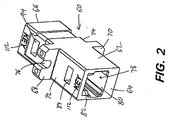
- FIGS 2-5 illustrate an exemplary adapter 60 constructed in accordance with the present invention.
- the adapter 60 is preferably formed of plastic and features a body 62 having two ends that will be referred to here as a user end 64 and a contractor end 66 .
- a central portion of the body 62 has outwardly extending flanges 68, 70 on the upper side 72 and lower side 74 , respectively, of the body 62 .
- the flanges 68, 70 have openings 76 for the disposal of bolts, screws or other connectors so that the adapter 60 might be easily affixed to a slot in a connector box (not shown) or a wall outlet box.
- openings 76 might also comprise holes such as those depicted in Figures 8 and 9.
- a clip (not shown) may be attached to the adapter 60 in the recessed portion 65 .
- the clip has outwardly extending tabs or flanges to provide a friction fit in a panel or outlet box.
- the user end 64 of the adapter 60 has a standard receptacle 78 formed therein.
- the opening of the standard receptacle 78 features a substantially rectangularly-shaped main entrance portion 80 that is shaped and sized to admit the housing 20 of a connector.
- On one side of the main entrance portion 80 is a lateral key slot 82 within which the key 45 of an MT-RJ connector 10 can be disposed. Because the key way 82 is only present on one side of the main entrance portion, an MT-RJ connector will only fit within the standard receptacle 78 when it is properly oriented with the adapter 60 in a standard orientation such that the key 45 can be disposed within the key slot 82 . This keying arrangement prevents the connector from being inserted into the user end 64 while in an improper orientation.
- Adjoining the key way 82 is a tab aperture 84 that is disposed through the body 62 .
- the tab aperture 84 is shaped and sized to admit the entrance of the locking tab 52 of an MT-RJ connector.
- the angled cam face 54 of the tab 84 permits the locking portion to be cammed downwardly toward the housing 20 so that the locking portion 50 can be slidingly inserted into the key way 82 .
- the tab 52 becomes aligned with the tab aperture 84 , it snaps into the aperture 84 .
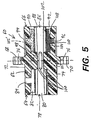
- the contractor end 66 includes a novel, non-standard receptacle 86 , which is best shown in Figures 3 and 5.
- the non-standard receptacle 86 features a central main entrance portion 88 with a pair of oppositely disposed first and second key ways 90, 92 located above and below the adjoining main entrance portion 88 .
- First and second tab apertures 94, 96 are associated with the first and second key ways 90, 92 , respectively, in the same manner as the tab aperture 84 was associated with the key way 82 on the user end 64 .
- Tab apertures 94, 96 are located in opposite side walls of adapter body 62 .
- a central passage 98 at the center of the body 62 of the adapter 60 allows communication between the main entrance portions 78 and 86 .
- Four inward projections 100 are shaped and sized to reside within the castellations 28 on the forward end of an MT-RJ connector.
- a key excluder 102 is shown in Figures 3 and 5.
- the key excluder 102 is shaped and sized to fit within one of the key ways 90,92 in the adapter 60 such that an MT-RJ connector key cannot be disposed within that passage.
- the key excluder 102, as well as the adapter 60, may be fashioned of plastic, metal, or any other suitable material.
- the key excluder 102 includes a longitudinal main body 104 having a slot 106 at one longitudinal end 107 and a notch 108 at the other longitudinal end.
- a tab 110 extends laterally from a mid-portion of the body 104 .
- the key excluder 102 also has extensions 111 (see Figure 3), which in the embodiment shown are bumps, but could also be ridges, or other protrusions to frictionally engage the sides of a key way 90 or 92 .
- Tab 110 is also sized to fit snugly in one of the tab apertures 94, 96 . It can be seen from Figure 5 that the longitudinal end 107 of the key excluder 102 thus lies flush with the first or user end 64 when inserted in either key way 90 or 92 .
- Notch 108 allows the key excluder 102 to be pried out of one of the retainers 90, 92 with a screwdriver, pocket knife, etc.
- the key excluder 102 is disposed within the lower key way 92 on the installer end 66 of the adapter body 62 .
- This configuration is depicted in solid lines in Figure 5.
- the main body 104 of the excluder 102 lies within the key way 92 while the tab 110 of the excluder is disposed within the tab aperture 96 .
- the slot 106 at the end of the body 104 receives one of the flanges 100 .
- an MT-RJ connector can only be inserted into the contractor end 66 of the adapter 60 in the standard orientation such that its key 45 is slidably inserted into the upper key way 90 .
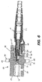
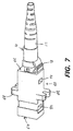
- Figures 6 and 7 show a connector seated in an adapter 60 .
- the standard orientation of the connector to the adapter 60 is an intended and preferred orientation as it permits a connection between connectors on the contractor and user ends 66, 64 to be mated for correct polarity when the connectors are correctly installed on their cable ends.
- the ferrules 42 of each connector will mate and permit transmission of data or information between the aligned optic fibers contained within each of the ferrules 42 .
- the key excluder 102 be provided to an installer or contractor in the default configuration described here and that this configuration not be changed unless necessary.
- the polarity of the fibers for the connector on the contractor end 66 can be quickly reversed.
- the key excluder 102 is removed from the lower key way 92 of the adapter body.
- a screwdriver blade (not shown) can be inserted into the screwdriver notch 108 and used to pry up the excluder 102 so that it can be withdrawn from the lower key way 92 .
- the key excluder 102 is then inserted into the upper key way 90 so that it is in the position shown for excluder 102' in Figure 5.
- the excluder body 104 lies within the upper passage 90 and the tab 110 fits within the upper key aperture 94 .
- the end slot 106 of the excluder 102 will receive the appropriate flange 100 on the upper side of the adapter body 62 .
- an MT-RJ connector may be inserted into the contractor end 66 in an inverted, or reverse, orientation.
- the locking portion 50 of the MT-RJ connector resides within the lower key way 92 and the locking tab 52 resides within the tab aperture 96 .
- printed indicia on the adapter 60 are used to assist in the proper placement of the key excluder 102 .
- the word “KEY” is printed in locations 112 on the upper side 72 of the adapter body 62 , indicating that the upper side 72 of the adapter body will accept the key 45 of an MT-RJ connector in the standard orientation.
- the words “REV KEY” 114 are printed on the lower side 74 of the adapter body 62 proximate the tab aperture 96 to indicate that the lower side 74 on the installer end 66 will accept a key 45 in a reversed orientation.
- any indicia may be used to indicate the standard and reversed orientations.
- the exemplary device described here only permits the orientation of the MT-RJ connector, and thus the polarity of the optic fiber cable 12 to be reversed, on one end of the adapter 60 . It is currently preferred to permit a contractor, but not a user, to reverse the polarity of the fiber optic connection.
- the contractor end 66 of an MT-RJ adapter 60 is depicted, having a main entrance portion 80 , a pair of lateral key ways 90 , 92 and tab apertures 94 and 96 (not shown).
- a removable clip 120 (shown removed from the adapter 60 in Figure 8) is used as the key excluder.
- the exemplary clip 120 shown in Figure 8 is generally U-shaped, having a pair of legs 122, 124 that are joined to one another by a central web 126 .
- One of the legs 122 presents an inwardly projecting raised portion 128 and an outwardly directed projection 130 .
- the key ways 90, 92 are partially defined by housing portions 132 and 134 that extend from the end surface 136 of the contractor side 66 to the respective tab aperture 94 , 96.
- the clip 120 performs the same function as the key excluder 102 described earlier to selectively block one of the two key ways 90, 92.
- the clip 120 is inserted into either key way by sliding disposal over one of the housing portions 132 or 134 so that one of the legs 124 is disposed on one side of the housing portion and the other leg 126 is disposed on the other side of the housing portion.
- the inwardly projecting raised portion 128 will reside within the respective tab aperture 94 or 96 .
- the respective key way 90 or 92 is blocked to prevent entry of a key. Removal of the clip 120 is accomplished by gripping portions of the clip 120 , such as the outwardly directed projection 130 and removing the clip 120 from its seated position.
- Figure 9 illustrates a further alternative embodiment wherein the key excluder is provided by a reversable cover 140 .
- the cover 140 has a face plate 142 and four adjoining side pieces 144 that define an opening 146 .
- the laterally-located two of the side pieces 144 present inwardly-directed ribs 145 that are shaped and sized to engage slots 147 on the contractor side 66 to help retain the cover 140 in a seated position on the contractor side 66 .
- the face plate 142 has an opening 148 that is slightly off-center so as to provide a panel 150 on one side of the face plate 142 .
- the opening 146 of the cover 140 is sized and shaped to receive the contractor side 66 of the adapter 60 therewithin so that when seated on the adapter 60 , the side pieces 144 are located on each side of the adapter 60 and the face plate 142 abuts the end surface 136 .
- the cover 142 is oriented as shown in Figure 9 and so seated, it will be understood that the panel 150 will block access to the lower key way 92 . However, the main entrance portion 88 and the upper key way 90 will remain accessible through the opening 148 . If the cover 140 is removed and seated on the adapter 60 in an inverted orientation, the panel 150 will block the upper key way 90 while the main entrance portion 88 and lower key way 92 can be accessed through the opening 148 .
- the cover 140 can be used to selectively block entry of the key 45 of a connector into either the upper or lower key way 90, 92 of the adapter 60 .
- Figure 10 depicts a side, cross-sectional view of an alternative exemplary MT-RJ adapter 150 that is configured to receive a pair of MT-RJ connectors (not shown) only in a reverse configuration.
- the connectors are insertable into the adapter 150 only in a configuration that is opposite from the manner in which they were originally intended.
- the adapter 150 provides a corrected interconnection for connectors when one of two connectors has a reversed polarity.
- the adapter 150 is similar in many respects to the adapter 60 described earlier. However, the contractor end 66 provides only a single key way 92 and single tab aperture 96 adjacent the main entrance portion 88 rather than the pair of key ways 90 , 92 and tab apertures 94,96 provided with the adapter 60 . As shown, the key way 92 is located on the opposite (lower) side of the adapter 150 from the key way 82 on the user side 64 . As a result of this reverse orientation of the key ways 82 , 92 , a connector inserted into the contractor end 66 can only be inserted in an orientation reversed from that of a connector inserted into the user end 64 . Thus, if a reverse polarity problem is detected where a standard adapter (having key ways on the user and contractor ends on the same side of the adapter) is used, the problem is correctable by substituting the reverse adapter 150 for the standard adapter.
- a reverse polarity problem is detected where a standard adapter (having key ways on the user and
- FIG 11 illustrates an exemplary SC-DC type connector 160 for the end of a fiber optic cable 162 having transmitting and receiving optical fibers 164, 166 .
- the SC-DC connector is a known connector that has an outer housing 168 that is roughly shaped as a rectangular block.
- a rubber sheath 170 acts as a bend limiter for the cable 162 .
- the housing 168 presents molded gripping areas 172 for manual engagement and gripping of the housing 168 .
- the housing 168 also includes a pair of recesses 174 (one shown) disposed on opposite sides of the housing 168 to retain complimentary locking flanges from an adapter.
- the housing also presents an outwardly extending orientation key 176 on one side.
- the key 176 is shaped and sized to fit within a complimentary slot in an adapter to ensure that the connector 160 is inserted into the adapter according to a predetermined orientation.
- the housing 168 contains a cylindrically shaped ferrule 178 within which are secured the optical fibers 164 and 166 .
- Figures 12 and 13 depict a standard, known adapter 180 for use in interconnecting a pair of SC-DC connectors of the type shown in Figure 11.
- the adapter 180 has an outer housing formed of two interengageable halves 182 , 184 , each of the halves defining a central passage 186 therethrough.
- the passages 186 are roughly rectangular in shape and sized to accommodate the housing of an SC-DC connector such as connector 160 .
- the halves 182 , 184 each have external recesses 188 into which a complimentary attachment clip (not shown) can fit for attaching the adapter 180 to a supporting frame or the like.
- Complimentary projections and recesses 190 are provided on the mating surfaces of the two halves 182 , 184 to ensure precise alignment and interengagement of the two halves 182 , 184 .
- the halves 182 , 184 each have complimentary outwardly extending flanges 192 with openings 194 for the disposal of bolts, screws or other connectors (not shown) so that the adapter 180 might be easily affixed to a slot in a connector box or a wall outlet box.
- the securing member 196 has a central web 198 that retains a hollow tubular plug 200 having a pair of openings 202,204 at either end.
- the plug 200 is centrally located within the passages 186 of each adapter half 182 , 184 .
- the openings 202 , 204 of the plug 200 are shaped and sized to receive the ferrule 178 of an SC-DC connector 160 .
- the securing member 196 also retains a pair of gripping members 206 , 208 . These gripping members 206, 208 present locking flanges 210 on either end that are shaped and sized to fit within a recess 174 of the housing 168 of an SC-DC connector 160 .
- Slots 212 and 214 are disposed in each of the adapter halves 182, 184 . It is noted that the slots 212, 214 will both be located on the same side, i.e., the lower side, of the adapter 180 when the adapter 180 is assembled. This placement of the slots 212, 214 ensures that connectors placed into the passages 186 of the halves 182 , 184 will be aligned so as to provide a proper interconnection for the transmitting and receiving fibers therewithin.
- an SC-DC connector 160 is placed into each of the passages 186 of the halves 182 , 184 .
- the key 176 of one of each of the two SC-DC connectors 160 will reside within one of the slots 212 , 214 .
- the ferrules 178 of the connectors 160 will be disposed within the openings 202 and 204 of the tubular plug 200 .
- the locking flanges 210 of the gripping members 206, 208 will snap into the recesses 174 on the housings 168 of the connectors 160 to secure the connectors 160 within the adapter 180 .
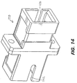
- FIG 14 illustrates a novel replacement adapter 220 for the adapter 180 just described.
- the replacement adapter 220 is constructed and operates in substantially the same manner as the adapter 180 .
- the replacement adapter 220 has slots 222 and 224 located on opposite sides of the adapter 220 rather than on the same side as slots 212 and 214 were for the adapter 180 .
- This placement of slots 222, 224 ensures that two inserted connectors 160 will have a reverse orientation with respect to one another, as it will be understood that one of the two connectors 160 will need to be inverted from the orientation used for insertion into the adapter 180 . It can be seen, then, that a reverse polarity problem can be corrected by substituting the reverse adapter 220 for the standard adapter 180 .
- an intermediate component such as a jumper
- a jumper can be disposed between a first connector and a second connector (or a wall outlet and an adapter) to provide polarity reversal.
- the jumper provides a structure that receives transmitting and receiving signals and reverses their physical positions.
- Figure 15 provides a schematic diagram for such a component.
- the jumper 230 which has two connectors 232 , 234 and two fibers 236 , 238 (which are also shown schematically for clarity purposes) is positioned between a first connector 240 and a second connector 242 , either one of which may be located in a wall or in an electrical component, for example.
- the connectors are depicted generally, and, it should be understood that these connectors may constitute any of the connectors discussed above, or even other styles of fiber optic connectors that may have their polarity reversed.
- connectors 240 and 242 have a reverse polarity problem.
- Connector 240 which has fibers 248 and 250 shown schematically, for clarity, has fiber 248 as the transmitting fiber and fiber 250 as the receiving fiber. (Arrows indicate the direction of light travel in the optical fibers.)
- connector 242 which also shows the fibers 252 and 254 schematically for clarity, has fiber 252 as the transmitting fiber and fiber 254 as the receiving fiber. If connectors 240 and 242 were directly connected (with a regular adapter or connector sleeve), the transmitting fibers and the receiving fibers would be aligned, resulting in no transmission of light through this junction.
- An exemplary jumper 230 has the two connectors 232 , 234 and two fibers 236, 238 extending between the connectors.
- Jumper 230 may be of any length, with the fibers 236 , 238 being of any length.
- the jumper may even be a solid piece, with no visible fibers between the connectors.
- the jumper 230 is then mechanically and optically connected to the connectors 240 , 242 by adapters 244, 246 .
- Adapters 244 and 246 may be similar to adapter 60 , which would be used in this case with both connectors keyed to the same side.
- regular (non-polarity reversing) adapters may also be used.
- the two fibers 236, 238 in jumper 230 cross over one another as they extend between connectors 232, 234 .
- fiber 236 mates with fiber 252 at one end and mates with fiber 250 at its other end.
- fiber 238 mates with fiber 248 at one end and with fiber 254 at the other end.
- the polarity reversal problem in the connectors 240, 242 will be corrected by the interpositioning of jumper 230 therebetween.
- the present invention has been described with respect to two of the more common varieties of connectors and adapters in use today: the SC-DC and the MT-RJ styles. It will be understood by one of skill in the art, however, that the devices and methods of the invention are applicable to other styles of keyed connectors and adapters, including the LC, VF-45, LX.5 and SC Duplex styles.
- Each of these connectors have a pair of side-by-side housings, each having an orientation key.
- Each of the housings contains an optical fiber ferrule that retains a single fiber therein.
- An adapter for the SC duplex has a pair of receptacles to receive the two housings. Each of the receptacles has a keyway to accommodate the orientation keys of the connector housings.
- Novel adapters could be constructed, in accordance with the present invention, that have the key ways in reversed positions at one end or that have selectively blockable keyways.
Abstract
Devices and methods are described that permit simple
correction of a fiber optic polarity reversal problem. An
adapter (60) is described having receptacles (78, 86) to
receive a connector on a first end, or user end, and on a
second end, or contractor end. Both the receptacles (78, 86)
provide keying arrangements so that the connectors can be
received only when correctly oriented with respect to the
adapter (60). The keying arrangement on the contractor end,
however, is reversable so that the connector may be inserted in
one of two predetermined orientations, at the behest of the
contractor or installer. Adapters (60) are also described that
receive connectors only in a physically reversed orientation to
counteract a reverse polarity condition. In addition, a jumper
is described that can be interposed between a connector and
adapter to correct a reverse polarity condition.
Description
- The present invention is directed to devices and methods for reversing the polarity of fiber optic cable connections. In particular aspects, the invention is directed to adapters for receiving and interconnecting cables having optical fibers therein.
- In the fiber optic communication field, cables are used that contain a pair of, or sometimes more, individual optical fibers. Connectors, two of which that are being used today include the SC-DC and the MT-RJ connectors, are placed on the ends of the cables to retain the fibers in a particular orientation and position with respect to one another. The connectors include ferrules to hold and align the optical fibers. The fibers are generally secured within the ferrule using epoxy and then polished to ensure clear signal transmission.
- When two optical cables must be joined at an interface, such as a wall or a connector panel, adapters are used to provide receptacles within which the connectors reside. Conventional adapters are similar in many respects to the well-known wall-mounted telephone jack that receives the connector on the end of a telephone cord and allows the wires inside the telephone cord to be interconnected with other circuits associated with the adapter. Like the connector for a telephone jack, fiber optic connector housings usually incorporate a keying arrangement that ensures that the connector can be inserted into the adapter only in a predetermined orientation with respect to the adapter.
- Unlike telephone jacks, however, fiber optic adapters are formed to receive two connectors from opposite ends. These two ends are sometimes referred to as the user end and contractor end. The adapter locates the two connectors in an end-to-end relation such that the fibers within the two connectors are aligned and light can be transmitted from the optical fibers within one of the connectors to the optical fibers in the other connector.
- Currently, fiber optic cables most often contain two optical fibers -- a transmitting fiber and a receiving fiber. When the two connectors are inserted into the adapter, the transmitting fiber of one connector is aligned with the receiving fiber of the other connector, and vice versa. Occasionally, these two fibers become inadvertently reversed when the connector is installed onto the end of the cable. If this occurs, the polarity of the connection will be reversed, and the fiber optic system will not work properly when the connectors are installed in the adapter. Until now, the only method for resolving such a problem has been for an installer to cut the connector off the end of the cable and install a new connector so that the fibers are properly arranged. Because of the requirement to use epoxy to secure the fibers, and polish the fiber ends, the procedure is difficult to accomplish in the field. Even when performed under the best circumstances, however, there are risks of errors in the installation of the connector or damage to the fiber optic elements. In addition, installers need to carry additional connectors along with them and, if those are forgotten, lost, or used up, correction of the problem can be extremely difficult.
- The present invention provides devices and methods that permit simple correction of a fiber optic polarity reversal problem. In particular embodiments, adapters are described having receptacles to receive a connector on a first end, or user end, and on a second end, or contractor end. Both the receptacles provide keying arrangements so that the connectors can be received only when correctly oriented with respect to the adapter. The keying arrangement on the contractor end, however, is reversible so that the connector may be inserted in one of two predetermined orientations, at the behest of the contractor or installer.
- In some preferred embodiments described herein, an adapter provides a non-standard receptacle on the contractor end having a main entrance that permits entry and residence of the housing for a connector, and a pair of key ways. One of the key ways is located on the upper side of the main entrance, while the other key way is located on the lower side. A key excluder is selectively disposable within either one of the key ways to prevent the key portion of a connector from being disposed within that key way.
- The adapter is preferably provided to a contractor and used in a "default" configuration in which the key excluder is placed in a predetermined one of the two key ways. This default configuration allows a connector to be received by the adapter on the contractor side in an orientation intended to correspond to a connector inserted into the user end so that polarity between the connectors is correct. In the event of a reverse polarity mistake, the installer removes the key excluder and inserts it in the other key way. This allows the connector on the contractor side to be inverted when reinserted to the adapter receptacle. A number of different configurations for key excluders are described.
- In alternative embodiment, adapters are described that only permit connectors to be inserted in a reverse configuration. This adapter can be substituted for a standard adapter when a polarity reversal problem is detected.
- Embodiments are described for correction of a polarity reversal problem to be corrected where either MT-RJ or SC-DC connectors are used.
- In a further embodiment, an exemplary jumper is described that can be interposed between a connector and adapter to reverse the polarity of the fibers associated with the connector.
- It is to be understood that both the foregoing general description and the following detailed description are exemplary and explanatory only and are not restrictive of the invention as claimed.
- The following drawings, which are incorporated, in and constitute a part of this specification, illustrate several embodiments of the invention and, together with the description, serve to explain the principles of the invention.
-
- Figure 1A is an isometric view of an exemplary prior art MT-RJ fiber optic cable end connector.
- Figure 1B is a cross-sectional side view of the connector shown in Figure 1A.
- Figure 2 is an isometric view of an exemplary MT-RJ adapter, constructed in accordance with the present invention, showing the user side of the adapter.
- Figures 3 and 4 are isometric views of the exemplary adapter shown in Figure 2, depicting the contractor side of the adapter.
- Figure 5 is a cross-sectional view of the adapter shown in Figures 2 and 3 with the key excluder disposed within the adapter.
- Figure 6 is a cross-sectional side view illustrating a connector seated within an adapter.
- Figure 7 is an isometric view of the arrangement shown in Figure 6.
- Figure 8 is an isometric view depicting the contractor side of an MT-RJ adapter, in accordance with the present invention, having an alternative key excluder.
- Figure 9 depicts the contractor side of an MT-RJ adapter, in accordance with the present invention, having another alternative key excluder.
- Figure 10 is a cross-sectional view of an MT-RJ style adapter configured to receive a pair of MT-RJ connectors in a reverse orientation.
- Figure 11 is an isometric view depicting an SC-DC connector of a type known in the art.
- Figure 12 is an exploded view of an exemplary SC-DC adapter configured to receive a pair of SC-DC connectors in a standard orientation.
- Figure 13 is a cross-sectional view of the adapter depicted in Figure 12.
- Figure 14 is an isometric view of an exemplary SC-DC adapter configured to receive a pair of SC-DC connectors in a reverse orientation.
- Figure 15 is a schematic drawing depicting an exemplary structure for a jumper in accordance with the present invention.
-
- Referring first to Figures 1A and 1B, there is shown an exemplary prior art fiber optic
cable end connector 10 shown affixed to one end of a fiberoptic cable 12. Thecable 12 includes an outer rubberizedcover 14 that contains transmitting and receivingoptic fibers optic fiber 16 is used to transmit a signal along its length from a source (not shown) toward theend connector 10. The receivingoptic fiber 18 receives a signal from the direction of theend connector 10 and transmits a signal along its length back to the source. - The
end connector 10 includes aplastic housing 20 and arubber cable sheath 22. As can be seen in Figure 1B, the transmitting and receivingfibers cable cover 14 and extend independently into thehousing 20. - The
plastic housing 20 is roughly block-shaped and defines achamber 24 therewithin that receives theindividual fibers forward end 26 of theplastic housing 20 presentscastellations 28 that are adapted to receive complimentary-shaped members in an adapter. Therear end 30 of thehousing 20 has a crimp body 32 that presents an exteriorradial surface 34 and aninterior bore 36. Thebore 36 has a radially enlarged portion 38 at the forward end to hold and center thespring member 44. Acrimp band 40, which is usually constructed from metal, is secured by crimping to the exteriorradial surface 34 of the crimp body 32 and secures that strength members (not shown) of thefiber optic cable 12. - The
chamber 24 of thehousing 20 encloses aferrule 42 that is biased toward and beyond theforward end 26 of thehousing 20 by aspring member 44 that is housed within thechamber 24 and centered by the enlarged portion 38 of the crimp body 32. The transmitting and receivingfibers crimp band 40, crimp body 32, the center of thespring member 44 and are secured inside theferrule 42 through apertures or fiber bores that cause thefibers - The exterior of the
housing 20 provides an outwardly extending orientation key 45 that is essentially a raised portion of thehousing 20. An integrally-moldedlatch 46 is also provided that includes ahinge portion 48 and a forwardly-extendinglocking portion 50. The lockingportion 50 features alocking tab 52 having a forwardly and upwardly facingangled cam face 54 and a rearwardly facingstop face 56. Thelatch 46 also includes a texturedthumb engagement portion 58 against which a user can exert pressure to move the lockingportion 50 of thelatch 46 downwardly against thehousing 20. - Figures 2-5 illustrate an
exemplary adapter 60 constructed in accordance with the present invention. Theadapter 60 is preferably formed of plastic and features abody 62 having two ends that will be referred to here as auser end 64 and acontractor end 66. A central portion of thebody 62 has outwardly extendingflanges upper side 72 andlower side 74, respectively, of thebody 62. Theflanges openings 76 for the disposal of bolts, screws or other connectors so that theadapter 60 might be easily affixed to a slot in a connector box (not shown) or a wall outlet box. Although slots are shown for theopenings 76 in Figures 2-4, it will be understood that theopenings 76 might also comprise holes such as those depicted in Figures 8 and 9. Alternatively, a clip (not shown) may be attached to theadapter 60 in the recessed portion 65. The clip has outwardly extending tabs or flanges to provide a friction fit in a panel or outlet box. - The
user end 64 of theadapter 60 has astandard receptacle 78 formed therein. The opening of thestandard receptacle 78 features a substantially rectangularly-shapedmain entrance portion 80 that is shaped and sized to admit thehousing 20 of a connector. On one side of themain entrance portion 80 is a lateralkey slot 82 within which the key 45 of an MT-RJ connector 10 can be disposed. Because thekey way 82 is only present on one side of the main entrance portion, an MT-RJ connector will only fit within thestandard receptacle 78 when it is properly oriented with theadapter 60 in a standard orientation such that the key 45 can be disposed within thekey slot 82. This keying arrangement prevents the connector from being inserted into theuser end 64 while in an improper orientation. - Adjoining the
key way 82 is atab aperture 84 that is disposed through thebody 62. Thetab aperture 84 is shaped and sized to admit the entrance of thelocking tab 52 of an MT-RJ connector. When an MT-RJ connector is slidingly disposed into thestandard receptacle 78, the angled cam face 54 of thetab 84 permits the locking portion to be cammed downwardly toward thehousing 20 so that the lockingportion 50 can be slidingly inserted into thekey way 82. When thetab 52 becomes aligned with thetab aperture 84, it snaps into theaperture 84. - It is pointed out that when an MT-RJ connector is seated within the
standard receptacle 78 so that itslocking tab 52 is disposed within theaperture 84, the connector cannot be inadvertently withdrawn since thestop face 56 of thetab 52 will matingly engage the side of theaperture 84. To remove the connector from thereceptacle 78, a user must depress theengagement portion 58 of thelatch 46 so that the lockingportion 50 is moved downwardly toward thehousing 20, thereby removing thetab 52 from theaperture 84 and permitting withdrawal, - The
contractor end 66 includes a novel,non-standard receptacle 86, which is best shown in Figures 3 and 5. Thenon-standard receptacle 86 features a centralmain entrance portion 88 with a pair of oppositely disposed first and secondkey ways main entrance portion 88. First andsecond tab apertures key ways tab aperture 84 was associated with thekey way 82 on theuser end 64.Tab apertures adapter body 62. - As Figure 5 shows, a central passage 98 at the center of the
body 62 of theadapter 60 allows communication between themain entrance portions castellations 28 on the forward end of an MT-RJ connector. - A
key excluder 102 is shown in Figures 3 and 5. Thekey excluder 102 is shaped and sized to fit within one of thekey ways adapter 60 such that an MT-RJ connector key cannot be disposed within that passage. Thekey excluder 102, as well as theadapter 60, may be fashioned of plastic, metal, or any other suitable material. Thekey excluder 102 includes a longitudinalmain body 104 having aslot 106 at onelongitudinal end 107 and anotch 108 at the other longitudinal end. Atab 110 extends laterally from a mid-portion of thebody 104. Thekey excluder 102 also has extensions 111 (see Figure 3), which in the embodiment shown are bumps, but could also be ridges, or other protrusions to frictionally engage the sides of akey way Tab 110 is also sized to fit snugly in one of the tab apertures 94, 96. It can be seen from Figure 5 that thelongitudinal end 107 of thekey excluder 102 thus lies flush with the first oruser end 64 when inserted in eitherkey way Notch 108 allows thekey excluder 102 to be pried out of one of theretainers - In a default or normal configuration, the
key excluder 102 is disposed within the lowerkey way 92 on theinstaller end 66 of theadapter body 62. This configuration is depicted in solid lines in Figure 5. As can be seen there, themain body 104 of theexcluder 102 lies within thekey way 92 while thetab 110 of the excluder is disposed within thetab aperture 96. Theslot 106 at the end of thebody 104 receives one of theflanges 100. - When the
key excluder 102 is installed in this default configuration, an MT-RJ connector can only be inserted into the contractor end 66 of theadapter 60 in the standard orientation such that its key 45 is slidably inserted into the upperkey way 90. Figures 6 and 7 show a connector seated in anadapter 60. The standard orientation of the connector to theadapter 60 is an intended and preferred orientation as it permits a connection between connectors on the contractor and user ends 66, 64 to be mated for correct polarity when the connectors are correctly installed on their cable ends. When two such connectors are inserted into theadapter 60 in this manner, theferrules 42 of each connector will mate and permit transmission of data or information between the aligned optic fibers contained within each of theferrules 42. As a result, it is preferred that thekey excluder 102 be provided to an installer or contractor in the default configuration described here and that this configuration not be changed unless necessary. - If it is determined that the
optic fibers contractor end 66 can be quickly reversed. Thekey excluder 102 is removed from the lowerkey way 92 of the adapter body. A screwdriver blade (not shown) can be inserted into thescrewdriver notch 108 and used to pry up theexcluder 102 so that it can be withdrawn from the lowerkey way 92. - The
key excluder 102 is then inserted into the upperkey way 90 so that it is in the position shown for excluder 102' in Figure 5. In this "reverse" position, theexcluder body 104 lies within theupper passage 90 and thetab 110 fits within the upperkey aperture 94. Theend slot 106 of theexcluder 102 will receive theappropriate flange 100 on the upper side of theadapter body 62. When thekey excluder 102 has been placed in this reverse configuration, an MT-RJ connector may be inserted into thecontractor end 66 in an inverted, or reverse, orientation. The lockingportion 50 of the MT-RJ connector resides within the lowerkey way 92 and thelocking tab 52 resides within thetab aperture 96. - It is noted that printed indicia on the
adapter 60 are used to assist in the proper placement of thekey excluder 102. As an example, the word "KEY" is printed inlocations 112 on theupper side 72 of theadapter body 62, indicating that theupper side 72 of the adapter body will accept the key 45 of an MT-RJ connector in the standard orientation. The words "REV KEY" 114 are printed on thelower side 74 of theadapter body 62 proximate thetab aperture 96 to indicate that thelower side 74 on theinstaller end 66 will accept a key 45 in a reversed orientation. However, any indicia may be used to indicate the standard and reversed orientations. - It can be seen that when the
key excluder 102 is installed in its default configuration, entry of an MT-RJ connector into thecontractor end 66 in an inverted orientation is prevented or locked out. Conversely, when thekey excluder 102 is installed in its reverse configuration, entry of an MT-RJ connector into the installer end in the standard orientation is locked out. - It is further pointed out that the exemplary device described here only permits the orientation of the MT-RJ connector, and thus the polarity of the
optic fiber cable 12 to be reversed, on one end of theadapter 60. It is currently preferred to permit a contractor, but not a user, to reverse the polarity of the fiber optic connection. - Referring now to Figure 8, an alternative embodiment of the invention is described. For clarity among the different embodiments, like reference numerals are used for like components. The
contractor end 66 of an MT-RJ adapter 60 is depicted, having amain entrance portion 80, a pair of lateralkey ways tab apertures 94 and 96 (not shown). - A removable clip 120 (shown removed from the
adapter 60 in Figure 8) is used as the key excluder. Theexemplary clip 120 shown in Figure 8 is generally U-shaped, having a pair oflegs central web 126. One of thelegs 122 presents an inwardly projecting raised portion 128 and an outwardly directedprojection 130. It is noted that thekey ways housing portions end surface 136 of thecontractor side 66 to therespective tab aperture - The
clip 120 performs the same function as thekey excluder 102 described earlier to selectively block one of the twokey ways clip 120 is inserted into either key way by sliding disposal over one of thehousing portions legs 124 is disposed on one side of the housing portion and theother leg 126 is disposed on the other side of the housing portion. When in a seated position, the inwardly projecting raised portion 128 will reside within therespective tab aperture clip 120 is so seated, the respectivekey way clip 120 is accomplished by gripping portions of theclip 120, such as the outwardly directedprojection 130 and removing theclip 120 from its seated position. - Figure 9 illustrates a further alternative embodiment wherein the key excluder is provided by a
reversable cover 140. Thecover 140 has a face plate 142 and fouradjoining side pieces 144 that define an opening 146. The laterally-located two of theside pieces 144 present inwardly-directedribs 145 that are shaped and sized to engageslots 147 on thecontractor side 66 to help retain thecover 140 in a seated position on thecontractor side 66. The face plate 142 has anopening 148 that is slightly off-center so as to provide apanel 150 on one side of the face plate 142. - The opening 146 of the
cover 140 is sized and shaped to receive thecontractor side 66 of theadapter 60 therewithin so that when seated on theadapter 60, theside pieces 144 are located on each side of theadapter 60 and the face plate 142 abuts theend surface 136. When the cover 142 is oriented as shown in Figure 9 and so seated, it will be understood that thepanel 150 will block access to the lowerkey way 92. However, themain entrance portion 88 and the upperkey way 90 will remain accessible through theopening 148. If thecover 140 is removed and seated on theadapter 60 in an inverted orientation, thepanel 150 will block the upperkey way 90 while themain entrance portion 88 and lowerkey way 92 can be accessed through theopening 148. Thus, thecover 140 can be used to selectively block entry of the key 45 of a connector into either the upper or lowerkey way adapter 60. - Figure 10 depicts a side, cross-sectional view of an alternative exemplary MT-
RJ adapter 150 that is configured to receive a pair of MT-RJ connectors (not shown) only in a reverse configuration. In other words, the connectors are insertable into theadapter 150 only in a configuration that is opposite from the manner in which they were originally intended. As a result, theadapter 150 provides a corrected interconnection for connectors when one of two connectors has a reversed polarity. - The
adapter 150 is similar in many respects to theadapter 60 described earlier. However, thecontractor end 66 provides only a singlekey way 92 andsingle tab aperture 96 adjacent themain entrance portion 88 rather than the pair ofkey ways tab apertures adapter 60. As shown, thekey way 92 is located on the opposite (lower) side of theadapter 150 from thekey way 82 on theuser side 64. As a result of this reverse orientation of thekey ways contractor end 66 can only be inserted in an orientation reversed from that of a connector inserted into theuser end 64. Thus, if a reverse polarity problem is detected where a standard adapter (having key ways on the user and contractor ends on the same side of the adapter) is used, the problem is correctable by substituting thereverse adapter 150 for the standard adapter. - Figure 11 illustrates an exemplary SC-
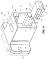
DC type connector 160 for the end of afiber optic cable 162 having transmitting and receivingoptical fibers outer housing 168 that is roughly shaped as a rectangular block. Arubber sheath 170 acts as a bend limiter for thecable 162. Thehousing 168 presents molded grippingareas 172 for manual engagement and gripping of thehousing 168. Thehousing 168 also includes a pair of recesses 174 (one shown) disposed on opposite sides of thehousing 168 to retain complimentary locking flanges from an adapter. The housing also presents an outwardly extendingorientation key 176 on one side. The key 176 is shaped and sized to fit within a complimentary slot in an adapter to ensure that theconnector 160 is inserted into the adapter according to a predetermined orientation. Thehousing 168 contains a cylindrically shapedferrule 178 within which are secured theoptical fibers - Figures 12 and 13 depict a standard, known adapter 180 for use in interconnecting a pair of SC-DC connectors of the type shown in Figure 11. The adapter 180 has an outer housing formed of two
interengageable halves central passage 186 therethrough. Thepassages 186 are roughly rectangular in shape and sized to accommodate the housing of an SC-DC connector such asconnector 160. Thehalves external recesses 188 into which a complimentary attachment clip (not shown) can fit for attaching the adapter 180 to a supporting frame or the like. Complimentary projections and recesses 190 are provided on the mating surfaces of the twohalves halves halves flanges 192 withopenings 194 for the disposal of bolts, screws or other connectors (not shown) so that the adapter 180 might be easily affixed to a slot in a connector box or a wall outlet box. - When the
halves member 196 therebetween. The securingmember 196 has acentral web 198 that retains a hollowtubular plug 200 having a pair of openings 202,204 at either end. Theplug 200 is centrally located within thepassages 186 of eachadapter half openings plug 200 are shaped and sized to receive theferrule 178 of an SC-DC connector 160. The securingmember 196 also retains a pair of grippingmembers members present locking flanges 210 on either end that are shaped and sized to fit within arecess 174 of thehousing 168 of an SC-DC connector 160. -
Slots slots slots passages 186 of thehalves DC connector 160 is placed into each of thepassages 186 of thehalves DC connectors 160 will reside within one of theslots ferrules 178 of theconnectors 160 will be disposed within theopenings tubular plug 200. When theconnectors 160 are fully seated within the adapter 180, the lockingflanges 210 of the grippingmembers recesses 174 on thehousings 168 of theconnectors 160 to secure theconnectors 160 within the adapter 180. - Figure 14 illustrates a
novel replacement adapter 220 for the adapter 180 just described. Thereplacement adapter 220 is constructed and operates in substantially the same manner as the adapter 180. However, thereplacement adapter 220 hasslots adapter 220 rather than on the same side asslots slots connectors 160 will have a reverse orientation with respect to one another, as it will be understood that one of the twoconnectors 160 will need to be inverted from the orientation used for insertion into the adapter 180. It can be seen, then, that a reverse polarity problem can be corrected by substituting thereverse adapter 220 for the standard adapter 180. - Also in accordance with the present invention, an intermediate component, such as a jumper, can be disposed between a first connector and a second connector (or a wall outlet and an adapter) to provide polarity reversal. The jumper provides a structure that receives transmitting and receiving signals and reverses their physical positions. Figure 15 provides a schematic diagram for such a component. The
jumper 230, which has twoconnectors fibers 236, 238 (which are also shown schematically for clarity purposes) is positioned between afirst connector 240 and asecond connector 242, either one of which may be located in a wall or in an electrical component, for example. The connectors are depicted generally, and, it should be understood that these connectors may constitute any of the connectors discussed above, or even other styles of fiber optic connectors that may have their polarity reversed. - As depicted in Figure 15,
connectors Connector 240, which hasfibers 248 and 250 shown schematically, for clarity, has fiber 248 as the transmitting fiber andfiber 250 as the receiving fiber. (Arrows indicate the direction of light travel in the optical fibers.) However,connector 242, which also shows thefibers fiber 252 as the transmitting fiber andfiber 254 as the receiving fiber. Ifconnectors - An
exemplary jumper 230 has the twoconnectors fibers Jumper 230 may be of any length, with thefibers - In order to reverse the polarity problem, the
jumper 230 is then mechanically and optically connected to theconnectors adapters Adapters adapter 60, which would be used in this case with both connectors keyed to the same side. Alternatively, regular (non-polarity reversing) adapters may also be used. The twofibers jumper 230 cross over one another as they extend betweenconnectors fiber 236 mates withfiber 252 at one end and mates withfiber 250 at its other end. Similarly,fiber 238 mates with fiber 248 at one end and withfiber 254 at the other end. As a result, the polarity reversal problem in theconnectors jumper 230 therebetween. - The present invention has been described with respect to two of the more common varieties of connectors and adapters in use today: the SC-DC and the MT-RJ styles. It will be understood by one of skill in the art, however, that the devices and methods of the invention are applicable to other styles of keyed connectors and adapters, including the LC, VF-45, LX.5 and SC Duplex styles. Each of these connectors have a pair of side-by-side housings, each having an orientation key. Each of the housings contains an optical fiber ferrule that retains a single fiber therein. An adapter for the SC duplex has a pair of receptacles to receive the two housings. Each of the receptacles has a keyway to accommodate the orientation keys of the connector housings. Novel adapters could be constructed, in accordance with the present invention, that have the key ways in reversed positions at one end or that have selectively blockable keyways.
- Furthermore, while the invention has been shown or described in only some of its forms, it should be apparent to those skilled in the art that it is not so limited, but is susceptible to various additional changes within departing from the scope of the invention.
Claims (13)
- An adapter (60) for receiving a connector (10) having an orientation key (45), the adapter (60) comprising:a housing defining a connector receptacle (86) having an entrance (88) to receive and retain the connector (10);a first key way (90) located in the housing proximate the entrance (88) to receive and guide the orientation key (45) during reception of the connector (10) within the adapter (60) in a first orientation; anda second key way (92) located in the housing proximate the entrance (88) to receive and guide the orientation key (45) during reception of the connector (10) within the adapter (60) in a second orientation, the first orientation being different from the second.
- The adapter (60) of claim 1 further comprising:a key excluder (102) configured to be selectively inserted into the second key way (92) to prohibit the orientation key (45) from being received within the second key way (92), but allow insertion of the key (45) into the first key way (90) with the connector (10) in the first orientation; andthe key excluder (102) configured also to be selectively insertable into the first key way (90) to prohibit the orientation key (45) from being received within the first key way (90), but allow insertion of the key (45) into the second key way (92) with the connector (10) in the second orientation.
- The adapter (60) of claim 1 wherein the first and second key ways (90, 92) each comprise a longitudinally slotted portion of the housing adjoining the entrance (88).
- The adapter (60) of claim 2 wherein the key excluder (102) comprises a longitudinal body portion (104) that is shaped and sized to lie within each of the key ways (90, 92) thereby precluding entry of the orientation key (45) into the key way (90, 92) in which the key excluder (102) is located.
- The adapter (60) of claim 2 further comprising written indicia (112, 114) upon the housing to indicate a default configuration for disposal of the key excluder (102) within the housing.
- The adapter of claim 1 wherein the housing defines a second connector receptacle located alongside the first connector receptacle in a side-by-side relation, the second connector receptacle having first and second key ways for selectively receiving the orientation key of a connector received within the second connector receptacle.
- An adapter (60) for retaining fiber optic first and second connectors (10) in a generally abutting relation, and maintaining consistent polarity between fibers in the connectors (10), comprising:a body (62) with a standard first receptacle (78) on a first end to selectively receive the first connector (10) therewithin, the first receptacle (78) having a configuration to receive the first connector (10) only when the first connector (10) is in a standard orientation; andthe body (62) of the adapter (60) having a second receptacle (86) on a second end to selectively receive the second connector (10) therewithin so that a mating relation between the first and second connectors (10) is established to form a connection, the second receptacle (86) having a standard configuration to receive the second connector (10) only when the second connector (10) is in a standard orientation to establish consistent polarity between the connectors (10); andthe second receptacle (86) being adjustable to a reverse configuration to receive the second connector (10) only when the second connector (10) is in a reverse orientation and polarity in the event that the polarity was inconsistent.
- The adapter (60) of claim 7 wherein the second receptacle (86) has a main entrance (88) and a pair of opposed key ways (90, 92) adjoining opposite walls of the main entrance (88), each of the key ways (90, 92) adapted to receive a key (45) mounted to the second connector (10), and wherein the adapter (60) further comprises a removable key excluder (102) that selectively blocks one of the key ways (90, 92), while in the standard configuration and in the other of the key ways (90, 92) while in the reverse configuration.
- The adapter (60) of claim 8 wherein the adapter (60) has upper and lower sidewalls, each of the sidewalls having:a tab aperture (94, 96) to secure a locking tab (52) of the second connector (10) in locking relation within the adapter body (62), and
wherein the key excluder (102) has a tab sized and shaped to fit within each of the tab apertures (94, 96). - The adapter (60) of claim 8 wherein the key excluder (102) has an outer end with a recess formed therein for receiving a screwdriver blade to enable the key excluder (102) to be pried from one of the key ways (90, 92).
- An adapter (60) for retaining fiber optic first and second connectors in a generally abutting relation, and correcting a reversed polarity condition for fibers in one of the connectors, comprising:a body (62) with a standard first receptacle (78) on a first end to selectively receive the first connector therewithin, the first receptacle (78) having a configuration to receive the first connector only when the first connector is in a standard orientation; andthe body (62) of the adapter (60) having a second receptacle (86) on a second end to selectively receive the second connector therewithin so that a mating relation between the first and second connectors is established to form a connection, the second receptacle (86) having a reverse configuration to receive the second connector only when the second connector is in a reverse orientation and polarity in the event that the polarity was inconsistent.
- The adapter (60) of claim 11 wherein the first and second receptacles (78, 86) are shaped and sized to each receive an MT-RJ connector.
- The adapter (60) of claim 11 wherein the first and second receptacles (78, 80) are shaped and sized to each receive an SC-DC connector.
Applications Claiming Priority (2)
| Application Number | Priority Date | Filing Date | Title |
|---|---|---|---|
| US09/343,763 US6634796B2 (en) | 1999-06-30 | 1999-06-30 | Polarity reversal for fiber optic connections |
| US343763 | 1999-06-30 |
Publications (1)
| Publication Number | Publication Date |
|---|---|
| EP1065542A1 true EP1065542A1 (en) | 2001-01-03 |
Family
ID=23347555
Family Applications (1)
| Application Number | Title | Priority Date | Filing Date |
|---|---|---|---|
| EP00113950A Withdrawn EP1065542A1 (en) | 1999-06-30 | 2000-06-30 | Polarity reversal for fiber optic connections |
Country Status (4)
| Country | Link |
|---|---|
| US (1) | US6634796B2 (en) |
| EP (1) | EP1065542A1 (en) |
| JP (1) | JP4202585B2 (en) |
| CA (1) | CA2308645A1 (en) |
Cited By (62)
| Publication number | Priority date | Publication date | Assignee | Title |
|---|---|---|---|---|
| US6364537B1 (en) | 2000-02-08 | 2002-04-02 | The Siemon Company | Dual polarity fiber optic adapter |
| WO2003050579A2 (en) * | 2001-09-28 | 2003-06-19 | Corning Cable Systems Llc | Fiber optic plug |
| US7568844B2 (en) | 2006-08-15 | 2009-08-04 | Corning Cable Systems Llc | Ruggedized fiber optic connector assembly |
| US7677814B2 (en) | 2007-05-06 | 2010-03-16 | Adc Telecommunications, Inc. | Mechanical interface converter for making non-ruggedized fiber optic connectors compatible with a ruggedized fiber optic adapter |
| US7686519B2 (en) | 2007-06-18 | 2010-03-30 | Adc Telecommunications, Inc. | Hardened fiber optic housing and cable assembly |
| US7722258B2 (en) | 2007-05-06 | 2010-05-25 | Adc Telecommunications, Inc. | Interface converter for SC fiber optic connectors |
| US7744286B2 (en) | 2007-12-11 | 2010-06-29 | Adc Telecommunications, Inc. | Hardened fiber optic connection system with multiple configurations |
| US7787740B2 (en) | 2008-06-12 | 2010-08-31 | Corning Cable Systems Llc | Universal cable bracket |
| USRE42522E1 (en) | 2003-09-08 | 2011-07-05 | Adc Telecommunications, Inc. | Ruggedized fiber optic connection |
| US8272792B2 (en) | 2008-09-30 | 2012-09-25 | Corning Cable Systems Llc | Retention bodies for fiber optic cable assemblies |
| US8285096B2 (en) | 2008-09-30 | 2012-10-09 | Corning Cable Systems Llc | Fiber optic cable assemblies and securing methods |
| US8303193B2 (en) | 2008-09-30 | 2012-11-06 | Corning Cable Systems Llc | Retention bodies for fiber optic cable assemblies |
| US8433171B2 (en) | 2009-06-19 | 2013-04-30 | Corning Cable Systems Llc | High fiber optic cable packing density apparatus |
| US8538226B2 (en) | 2009-05-21 | 2013-09-17 | Corning Cable Systems Llc | Fiber optic equipment guides and rails configured with stopping position(s), and related equipment and methods |
| US8542973B2 (en) | 2010-04-23 | 2013-09-24 | Ccs Technology, Inc. | Fiber optic distribution device |
| WO2013155395A1 (en) * | 2012-04-13 | 2013-10-17 | Corning Cable Systems Llc | Adapter for fiber optic connectors |
| US8593828B2 (en) | 2010-02-04 | 2013-11-26 | Corning Cable Systems Llc | Communications equipment housings, assemblies, and related alignment features and methods |
| US8625950B2 (en) | 2009-12-18 | 2014-01-07 | Corning Cable Systems Llc | Rotary locking apparatus for fiber optic equipment trays and related methods |
| US8660397B2 (en) | 2010-04-30 | 2014-02-25 | Corning Cable Systems Llc | Multi-layer module |
| US8662760B2 (en) | 2010-10-29 | 2014-03-04 | Corning Cable Systems Llc | Fiber optic connector employing optical fiber guide member |
| US8699838B2 (en) | 2009-05-14 | 2014-04-15 | Ccs Technology, Inc. | Fiber optic furcation module |
| US8705926B2 (en) | 2010-04-30 | 2014-04-22 | Corning Optical Communications LLC | Fiber optic housings having a removable top, and related components and methods |
| US8712206B2 (en) | 2009-06-19 | 2014-04-29 | Corning Cable Systems Llc | High-density fiber optic modules and module housings and related equipment |
| US8718436B2 (en) | 2010-08-30 | 2014-05-06 | Corning Cable Systems Llc | Methods, apparatuses for providing secure fiber optic connections |
| US8770862B2 (en) | 2007-01-24 | 2014-07-08 | Adc Telecommunications, Inc. | Hardened fiber optic connector |
| US8879881B2 (en) | 2010-04-30 | 2014-11-04 | Corning Cable Systems Llc | Rotatable routing guide and assembly |
| US8913866B2 (en) | 2010-03-26 | 2014-12-16 | Corning Cable Systems Llc | Movable adapter panel |
| US8953924B2 (en) | 2011-09-02 | 2015-02-10 | Corning Cable Systems Llc | Removable strain relief brackets for securing fiber optic cables and/or optical fibers to fiber optic equipment, and related assemblies and methods |
| US8965168B2 (en) | 2010-04-30 | 2015-02-24 | Corning Cable Systems Llc | Fiber management devices for fiber optic housings, and related components and methods |
| US8985862B2 (en) | 2013-02-28 | 2015-03-24 | Corning Cable Systems Llc | High-density multi-fiber adapter housings |
| US8989547B2 (en) | 2011-06-30 | 2015-03-24 | Corning Cable Systems Llc | Fiber optic equipment assemblies employing non-U-width-sized housings and related methods |
| US8995812B2 (en) | 2012-10-26 | 2015-03-31 | Ccs Technology, Inc. | Fiber optic management unit and fiber optic distribution device |
| US9008485B2 (en) | 2011-05-09 | 2015-04-14 | Corning Cable Systems Llc | Attachment mechanisms employed to attach a rear housing section to a fiber optic housing, and related assemblies and methods |
| US9020320B2 (en) | 2008-08-29 | 2015-04-28 | Corning Cable Systems Llc | High density and bandwidth fiber optic apparatuses and related equipment and methods |
| US9022814B2 (en) | 2010-04-16 | 2015-05-05 | Ccs Technology, Inc. | Sealing and strain relief device for data cables |
| US9042702B2 (en) | 2012-09-18 | 2015-05-26 | Corning Cable Systems Llc | Platforms and systems for fiber optic cable attachment |
| US9038832B2 (en) | 2011-11-30 | 2015-05-26 | Corning Cable Systems Llc | Adapter panel support assembly |
| US9059578B2 (en) | 2009-02-24 | 2015-06-16 | Ccs Technology, Inc. | Holding device for a cable or an assembly for use with a cable |
| US9075217B2 (en) | 2010-04-30 | 2015-07-07 | Corning Cable Systems Llc | Apparatuses and related components and methods for expanding capacity of fiber optic housings |
| US9116324B2 (en) | 2010-10-29 | 2015-08-25 | Corning Cable Systems Llc | Stacked fiber optic modules and fiber optic equipment configured to support stacked fiber optic modules |
| US9213161B2 (en) | 2010-11-05 | 2015-12-15 | Corning Cable Systems Llc | Fiber body holder and strain relief device |
| US9239441B2 (en) | 2000-05-26 | 2016-01-19 | Corning Cable Systems Llc | Fiber optic drop cables and preconnectorized assemblies having toning portions |
| US9250409B2 (en) | 2012-07-02 | 2016-02-02 | Corning Cable Systems Llc | Fiber-optic-module trays and drawers for fiber-optic equipment |
| US9279951B2 (en) | 2010-10-27 | 2016-03-08 | Corning Cable Systems Llc | Fiber optic module for limited space applications having a partially sealed module sub-assembly |
| US9519118B2 (en) | 2010-04-30 | 2016-12-13 | Corning Optical Communications LLC | Removable fiber management sections for fiber optic housings, and related components and methods |
| US9632270B2 (en) | 2010-04-30 | 2017-04-25 | Corning Optical Communications LLC | Fiber optic housings configured for tool-less assembly, and related components and methods |
| US9645317B2 (en) | 2011-02-02 | 2017-05-09 | Corning Optical Communications LLC | Optical backplane extension modules, and related assemblies suitable for establishing optical connections to information processing modules disposed in equipment racks |
| US9720195B2 (en) | 2010-04-30 | 2017-08-01 | Corning Optical Communications LLC | Apparatuses and related components and methods for attachment and release of fiber optic housings to and from an equipment rack |
| US10094996B2 (en) | 2008-08-29 | 2018-10-09 | Corning Optical Communications, Llc | Independently translatable modules and fiber optic equipment trays in fiber optic equipment |
| US10359577B2 (en) | 2017-06-28 | 2019-07-23 | Corning Research & Development Corporation | Multiports and optical connectors with rotationally discrete locking and keying features |
| US10379298B2 (en) | 2017-06-28 | 2019-08-13 | Corning Research & Development Corporation | Fiber optic connectors and multiport assemblies including retention features |
| US10444443B2 (en) | 2013-06-27 | 2019-10-15 | CommScope Connectivity Belgium BVBA | Fiber optic cable anchoring device for use with fiber optic connectors and methods of using the same |
| EP2821829B1 (en) * | 2013-07-01 | 2020-01-08 | Fibrefab Limited | Fibre optic adapter and method for optically connecting fibre optic devices together |
| TWI714705B (en) * | 2016-01-15 | 2021-01-01 | 美商扇港元器件有限公司 | Fiber optic connector assemblies with adjustable polarity |
| US11187859B2 (en) | 2017-06-28 | 2021-11-30 | Corning Research & Development Corporation | Fiber optic connectors and methods of making the same |
| US11294133B2 (en) | 2019-07-31 | 2022-04-05 | Corning Research & Development Corporation | Fiber optic networks using multiports and cable assemblies with cable-to-connector orientation |
| US11294136B2 (en) | 2008-08-29 | 2022-04-05 | Corning Optical Communications LLC | High density and bandwidth fiber optic apparatuses and related equipment and methods |
| US11536921B2 (en) | 2020-02-11 | 2022-12-27 | Corning Research & Development Corporation | Fiber optic terminals having one or more loopback assemblies |
| US11604320B2 (en) | 2020-09-30 | 2023-03-14 | Corning Research & Development Corporation | Connector assemblies for telecommunication enclosures |
| US11686913B2 (en) | 2020-11-30 | 2023-06-27 | Corning Research & Development Corporation | Fiber optic cable assemblies and connector assemblies having a crimp ring and crimp body and methods of fabricating the same |
| US11880076B2 (en) | 2020-11-30 | 2024-01-23 | Corning Research & Development Corporation | Fiber optic adapter assemblies including a conversion housing and a release housing |
| US11927810B2 (en) | 2020-11-30 | 2024-03-12 | Corning Research & Development Corporation | Fiber optic adapter assemblies including a conversion housing and a release member |
Families Citing this family (65)
| Publication number | Priority date | Publication date | Assignee | Title |
|---|---|---|---|---|
| US6830382B1 (en) * | 2001-12-20 | 2004-12-14 | National Semiconductor Corporation | Miniature form-factor connecter for fiber optic modules |
| JP3800606B2 (en) * | 2002-12-27 | 2006-07-26 | 日本航空電子工業株式会社 | Optical connector adapter |
| US20050058401A1 (en) * | 2003-07-07 | 2005-03-17 | Charles Maynard | Keyed adapter and connector |
| US20050111796A1 (en) * | 2003-11-26 | 2005-05-26 | Matasek Jeffrey A. | Adaptor for reducing EMI |
| US7008117B2 (en) * | 2003-12-23 | 2006-03-07 | Amphenol Corporation | Optical connector assembly with features for ease of use |
| US7059779B2 (en) * | 2004-02-19 | 2006-06-13 | Albert Wooi Quan Khor | Optical fiber receptacle adaptor |
| EP1849031A2 (en) * | 2005-01-12 | 2007-10-31 | Adamant Kogyo Co., Ltd. | Multi fiber optical interconnect system, with push-push type insertion/withdrawal mechanism, mt-type connector and shuttered adapter and method for using same |
| US7284912B2 (en) | 2005-01-12 | 2007-10-23 | Illum Technologies, Inc. | Multi fiber optical interconnect system, with push—push type insertion/withdrawal mechanism, MT-type connector and shuttered adapter and method for using same |
| US7261472B2 (en) * | 2005-01-12 | 2007-08-28 | Illum Technologies, Inc. | Ultra-small, form factor single fiber optical interconnect system, with push-push type insertion/withdrawal mechanism and shuttered modular connector and shuttered adapter and method for using same |
| US7387447B2 (en) * | 2006-09-15 | 2008-06-17 | Corning Cable Systems Llc | Secure fiber optic connector and adapter systems |
| US7985027B2 (en) * | 2006-11-14 | 2011-07-26 | Corning Cable Systems Llc | Adapter assembly for coupling dissimilar fiber optic connectors |
| US7806599B2 (en) * | 2007-05-04 | 2010-10-05 | Illum Technologies, Inc. | Super miniature, single fiber optical interconnect system with parallel slider push-push type insertion/withdrawal mechanism and method for using same |
| US7717625B2 (en) * | 2007-08-13 | 2010-05-18 | Illum Technologies, Inc. | High density fiber optic interconnect system with push-release mechanism and method for using same |
| US7674048B2 (en) * | 2007-10-30 | 2010-03-09 | Corning Cable Systems Llc | Polarity checking apparatus for multi-fiber connectors |
| WO2009073500A1 (en) * | 2007-11-30 | 2009-06-11 | Adc Telecommunications, Inc. | Hybrid fiber/copper connector system and method |
| US8152385B2 (en) * | 2009-02-27 | 2012-04-10 | Corning Cable Systems Llc | Duplex fiber optic assemblies suitable for polarity reversal and methods therefor |
| ES2398782T3 (en) * | 2009-09-03 | 2013-03-21 | Tyco Electronics Raychem Bvba | Fiber optic connector assembly and fiber termination unit |
| JP4801766B2 (en) * | 2009-10-01 | 2011-10-26 | 日本航空電子工業株式会社 | Adapter set |
| US8636424B2 (en) * | 2010-10-22 | 2014-01-28 | Panduit Corp. | Optical communication connector |
| US11493701B2 (en) | 2010-10-22 | 2022-11-08 | Panduit Corp. | Optical communications connectors |
| JP5390582B2 (en) * | 2011-11-25 | 2014-01-15 | 三和電気工業株式会社 | Light outlet |
| US8770863B2 (en) * | 2012-06-04 | 2014-07-08 | Corning Cable Systems Llc | Multi-fiber fiber-optic connector with switchable polarity key |
| US20140064688A1 (en) * | 2012-09-04 | 2014-03-06 | Ezontek Technologies Co., Ltd. | Optical fiber adapter |
| US9726832B2 (en) * | 2013-04-08 | 2017-08-08 | Optical Fiber Packaging Corp. | Secure SC optical fiber connector and removal tools |
| TWI533538B (en) * | 2013-08-12 | 2016-05-11 | 亞旭電腦股份有限公司 | Fixing bracket for signal connector |
| US10079461B1 (en) | 2013-10-02 | 2018-09-18 | Western Digital Technologies, Inc. | Reversible plug |
| US9310569B2 (en) * | 2014-02-21 | 2016-04-12 | Alliance Fiber Optic Products, Inc. | Reconfigurable fiber optic adapter |
| US9829645B2 (en) * | 2014-06-30 | 2017-11-28 | Nexans | Reversible polarity MPO fiber optic connector |
| WO2016100078A1 (en) * | 2014-12-19 | 2016-06-23 | 3M Innovative Properties Company | Ruggedized optical fiber connection structures and assemblies |
| KR101774013B1 (en) * | 2015-07-28 | 2017-09-07 | 주식회사 샤펜프렛 | Optical adapter |
| US10712507B2 (en) | 2015-12-19 | 2020-07-14 | US Conec, Ltd | Field changeable fiber optic connector polarity keying |
| US9880361B2 (en) | 2015-12-19 | 2018-01-30 | Us Conec Ltd. | Field changeable fiber optic connector polarity keying with color coding |
| US9726830B1 (en) | 2016-06-28 | 2017-08-08 | Senko Advanced Components, Inc. | Connector and adapter system for two-fiber mechanical transfer type ferrule |
| US10444444B2 (en) | 2017-01-30 | 2019-10-15 | Senko Advanced Components, Inc. | Remote release tab connector assembly |
| US11333836B2 (en) | 2017-01-30 | 2022-05-17 | Senko Advanced Components, Inc. | Adapter for optical connectors |
| WO2018140981A1 (en) | 2017-01-30 | 2018-08-02 | Senko Advanced Components, Inc. | Optical connectors with reversible polarity |
| US10281668B2 (en) | 2017-07-14 | 2019-05-07 | Senko Advanced Components, Inc. | Ultra-small form factor optical connectors |
| US10718911B2 (en) | 2017-08-24 | 2020-07-21 | Senko Advanced Components, Inc. | Ultra-small form factor optical connectors using a push-pull boot receptacle release |
| US11822133B2 (en) | 2017-07-14 | 2023-11-21 | Senko Advanced Components, Inc. | Ultra-small form factor optical connector and adapter |
| US10705300B2 (en) | 2017-07-14 | 2020-07-07 | Senko Advanced Components, Inc. | Small form factor fiber optic connector with multi-purpose boot assembly |
| JP1595344S (en) * | 2017-08-31 | 2018-01-22 | ||
| US11002923B2 (en) | 2017-11-21 | 2021-05-11 | Senko Advanced Components, Inc. | Fiber optic connector with cable boot release having a two-piece clip assembly |
| JP1609805S (en) * | 2018-01-10 | 2018-07-23 | ||
| JP1609622S (en) * | 2018-01-10 | 2018-07-23 | ||
| WO2019183070A2 (en) | 2018-03-19 | 2019-09-26 | Senko Advanced Components, Inc. | Removal tool for removing a plural of micro optical connectors from an adapter interface |
| CN112088327A (en) | 2018-07-15 | 2020-12-15 | 扇港元器件股份有限公司 | Ultra-small optical connector and adapter |
| US11073664B2 (en) | 2018-08-13 | 2021-07-27 | Senko Advanced Components, Inc. | Cable boot assembly for releasing fiber optic connector from a receptacle |
| US10921530B2 (en) | 2018-09-12 | 2021-02-16 | Senko Advanced Components, Inc. | LC type connector with push/pull assembly for releasing connector from a receptacle using a cable boot |
| US11086087B2 (en) | 2018-09-12 | 2021-08-10 | Senko Advanced Components, Inc. | LC type connector with clip-on push/pull tab for releasing connector from a receptacle using a cable boot |
| US10921531B2 (en) | 2018-09-12 | 2021-02-16 | Senko Advanced Components, Inc. | LC type connector with push/pull assembly for releasing connector from a receptacle using a cable boot |
| US11806831B2 (en) | 2018-11-21 | 2023-11-07 | Senko Advanced Components, Inc. | Fixture and method for polishing fiber optic connector ferrules |
| US11175464B2 (en) | 2018-11-25 | 2021-11-16 | Senko Advanced Components, Inc. | Open ended spring body for use in an optical fiber connector |
| WO2020198755A1 (en) | 2019-03-28 | 2020-10-01 | Senko Advanced Components, Inc | Fiber optic adapter assembly |
| US11340406B2 (en) | 2019-04-19 | 2022-05-24 | Senko Advanced Components, Inc. | Small form factor fiber optic connector with resilient latching mechanism for securing within a hook-less receptacle |
| US11422312B2 (en) | 2019-05-09 | 2022-08-23 | Commscope Technologies Llc | Fiber optic converter |
| WO2020252355A1 (en) | 2019-06-13 | 2020-12-17 | Senko Advanced Components, Inc | Lever actuated latch arm for releasing a fiber optic connector from a receptacle port and method of use |
| US11467354B2 (en) | 2019-07-23 | 2022-10-11 | Senko Advanced Components, Inc. | Ultra-small form factor receptacle for receiving a fiber optic connector opposing a ferrule assembly |
| CN116520503A (en) * | 2019-09-17 | 2023-08-01 | 美国康涅克有限公司 | Card sleeve push |
| CN114730050A (en) * | 2019-11-20 | 2022-07-08 | 扇港元器件有限公司 | Reversible polarity optical fiber connector |
| TWM593556U (en) * | 2019-11-26 | 2020-04-11 | 大陸商深圳望得源科技有限公司 | Optical fiber connector and optical fiber connector |
| CN112904504B (en) * | 2019-12-04 | 2022-09-30 | 烽火通信科技股份有限公司 | Preformed end type extension splicing box |
| US11163123B2 (en) * | 2020-01-14 | 2021-11-02 | Ezconn Corporation | Duplex fiber optic adapter |
| US11226452B2 (en) | 2020-05-11 | 2022-01-18 | Google Llc | Dual polarity optical fiber adaptor with protruding tab and patch panel |
| TWM615335U (en) * | 2020-09-23 | 2021-08-11 | 建毅科技股份有限公司 | Optical fibre connector |
| TWM618319U (en) * | 2021-07-05 | 2021-10-11 | 建毅科技股份有限公司 | Fiber adapter |
Citations (4)
| Publication number | Priority date | Publication date | Assignee | Title |
|---|---|---|---|---|
| GB2069175A (en) * | 1980-02-04 | 1981-08-19 | Bunker Ramo | Plug-socket-plug fibre optic connector |
| DE9102805U1 (en) * | 1990-03-09 | 1991-05-29 | Amp Inc., Harrisburg, Pa., Us | |
| US5727102A (en) * | 1995-11-09 | 1998-03-10 | Electronics And Telecommunications Research Institute | Multifiber optical connector for optical ribbon cable |
| US5729644A (en) * | 1996-02-26 | 1998-03-17 | Alcoa Fujikura Limited | Receptacle for multi-fiber connector |
Family Cites Families (6)
| Publication number | Priority date | Publication date | Assignee | Title |
|---|---|---|---|---|
| US5166995A (en) * | 1984-06-08 | 1992-11-24 | Amp Incorporated | Polarized connector |
| US5335301A (en) * | 1993-05-05 | 1994-08-02 | Methode Electronics, Inc. | Fiber optic connector with sliding key |
| US5475781A (en) * | 1994-09-15 | 1995-12-12 | Chang; Peter C. | Optical fiber connector assembly with loop-back structure |
| US5521997A (en) * | 1995-02-28 | 1996-05-28 | The Whitaker Corporation | Rotatably polarizing keying element for a polarized connector |
| US5712938A (en) * | 1996-05-30 | 1998-01-27 | Tai Jin Mold Mfg. Co. | Optical fiber connector |
| US6173099B1 (en) * | 1998-06-05 | 2001-01-09 | Stratos Lightwave, Inc. | Snap-in coupling |
-
1999
- 1999-06-30 US US09/343,763 patent/US6634796B2/en not_active Expired - Lifetime
-
2000
- 2000-05-17 CA CA002308645A patent/CA2308645A1/en not_active Abandoned
- 2000-06-30 EP EP00113950A patent/EP1065542A1/en not_active Withdrawn
- 2000-06-30 JP JP2000199049A patent/JP4202585B2/en not_active Expired - Fee Related
Patent Citations (4)
| Publication number | Priority date | Publication date | Assignee | Title |
|---|---|---|---|---|
| GB2069175A (en) * | 1980-02-04 | 1981-08-19 | Bunker Ramo | Plug-socket-plug fibre optic connector |
| DE9102805U1 (en) * | 1990-03-09 | 1991-05-29 | Amp Inc., Harrisburg, Pa., Us | |
| US5727102A (en) * | 1995-11-09 | 1998-03-10 | Electronics And Telecommunications Research Institute | Multifiber optical connector for optical ribbon cable |
| US5729644A (en) * | 1996-02-26 | 1998-03-17 | Alcoa Fujikura Limited | Receptacle for multi-fiber connector |
Cited By (132)
| Publication number | Priority date | Publication date | Assignee | Title |
|---|---|---|---|---|
| US6364537B1 (en) | 2000-02-08 | 2002-04-02 | The Siemon Company | Dual polarity fiber optic adapter |
| US9239441B2 (en) | 2000-05-26 | 2016-01-19 | Corning Cable Systems Llc | Fiber optic drop cables and preconnectorized assemblies having toning portions |
| US10114176B2 (en) | 2000-05-26 | 2018-10-30 | Corning Optical Communications LLC | Fiber optic drop cables and preconnectorized assemblies |
| WO2003050579A2 (en) * | 2001-09-28 | 2003-06-19 | Corning Cable Systems Llc | Fiber optic plug |
| WO2003050579A3 (en) * | 2001-09-28 | 2003-10-09 | Corning Cable Sys Llc | Fiber optic plug |
| US6648520B2 (en) | 2001-09-28 | 2003-11-18 | Corning Cable Systems Llc | Fiber optic plug |
| US6899467B2 (en) | 2001-09-28 | 2005-05-31 | Corning Cable Systems Llc | Fiber optic plug and receptacle assembly |
| EP1775610A2 (en) * | 2001-09-28 | 2007-04-18 | Corning Cable Systems LLC | Fiber optic plug |
| EP1775610A3 (en) * | 2001-09-28 | 2007-07-04 | Corning Cable Systems LLC | Fiber optic plug |
| EP3550342A3 (en) * | 2001-09-28 | 2019-12-18 | Corning Optical Communications LLC | Fiber optic plug |
| USRE42522E1 (en) | 2003-09-08 | 2011-07-05 | Adc Telecommunications, Inc. | Ruggedized fiber optic connection |
| US8523455B2 (en) | 2006-08-15 | 2013-09-03 | Corning Cable Systems Llc | Ruggedized fiber optic connector assembly |
| US7568844B2 (en) | 2006-08-15 | 2009-08-04 | Corning Cable Systems Llc | Ruggedized fiber optic connector assembly |
| US11409057B2 (en) | 2007-01-24 | 2022-08-09 | Commscope Technologies Llc | Hardened fiber optic connector |
| US10877224B2 (en) | 2007-01-24 | 2020-12-29 | Commscope Technologies Llc | Fiber optic adapter |
| US8770862B2 (en) | 2007-01-24 | 2014-07-08 | Adc Telecommunications, Inc. | Hardened fiber optic connector |
| US9664862B2 (en) | 2007-01-24 | 2017-05-30 | Commscope Technologies Llc | Hardened fiber optic connector |
| US7722258B2 (en) | 2007-05-06 | 2010-05-25 | Adc Telecommunications, Inc. | Interface converter for SC fiber optic connectors |
| US7677814B2 (en) | 2007-05-06 | 2010-03-16 | Adc Telecommunications, Inc. | Mechanical interface converter for making non-ruggedized fiber optic connectors compatible with a ruggedized fiber optic adapter |
| US8128294B2 (en) | 2007-05-06 | 2012-03-06 | Adc Telecommunications, Inc. | Interface converter for SC fiber optic connectors |
| US8137002B2 (en) | 2007-05-06 | 2012-03-20 | Adc Telecommunications, Inc. | Mechanical interface converter for making non-ruggedized fiber optic connectors compatible with a ruggedized fiber optic adapter |
| US7686519B2 (en) | 2007-06-18 | 2010-03-30 | Adc Telecommunications, Inc. | Hardened fiber optic housing and cable assembly |
| US7959361B2 (en) | 2007-12-11 | 2011-06-14 | Adc Telecommunications, Inc. | Hardened fiber optic connection system |
| US10101538B2 (en) | 2007-12-11 | 2018-10-16 | Commscope Technologies Llc | Hardened fiber optic connector compatible with hardened and non-hardened fiber optic adapters |
| US8414196B2 (en) | 2007-12-11 | 2013-04-09 | Adc Telecommunications, Inc. | Optical fiber connection system with locking member |
| US8202008B2 (en) | 2007-12-11 | 2012-06-19 | Adc Telecommunications, Inc. | Hardened fiber optic connection system with multiple configurations |
| US7942590B2 (en) | 2007-12-11 | 2011-05-17 | Adc Telecommunications, Inc. | Hardened fiber optic connector and cable assembly with multiple configurations |
| US10746939B2 (en) | 2007-12-11 | 2020-08-18 | Commscope Technologies Llc | Hardened fiber optic connector compatible with hardened and non-hardened fiber optic adapters |
| US11867950B2 (en) | 2007-12-11 | 2024-01-09 | Commscope Technologies Llc | Hardened fiber optic connector compatible with hardened and non-hardened fiber optic adapters |
| US9482829B2 (en) | 2007-12-11 | 2016-11-01 | Commscope Technologies Llc | Hardened fiber optic connector compatible with hardened and non-hardened fiber optic adapters |
| US7762726B2 (en) | 2007-12-11 | 2010-07-27 | Adc Telecommunications, Inc. | Hardened fiber optic connection system |
| US7744288B2 (en) | 2007-12-11 | 2010-06-29 | Adc Telecommunications, Inc. | Hardened fiber optic connector compatible with hardened and non-hardened fiber optic adapters |
| US11275220B2 (en) | 2007-12-11 | 2022-03-15 | Commscope Technologies Llc | Hardened fiber optic connector compatible with hardened and non-hardened fiber optic adapters |
| US7744286B2 (en) | 2007-12-11 | 2010-06-29 | Adc Telecommunications, Inc. | Hardened fiber optic connection system with multiple configurations |
| US7787740B2 (en) | 2008-06-12 | 2010-08-31 | Corning Cable Systems Llc | Universal cable bracket |
| US10852499B2 (en) | 2008-08-29 | 2020-12-01 | Corning Optical Communications LLC | High density and bandwidth fiber optic apparatuses and related equipment and methods |
| US10222570B2 (en) | 2008-08-29 | 2019-03-05 | Corning Optical Communications LLC | Independently translatable modules and fiber optic equipment trays in fiber optic equipment |
| US10459184B2 (en) | 2008-08-29 | 2019-10-29 | Corning Optical Communications LLC | High density and bandwidth fiber optic apparatuses and related equipment and methods |
| US10422971B2 (en) | 2008-08-29 | 2019-09-24 | Corning Optical Communicatinos LLC | High density and bandwidth fiber optic apparatuses and related equipment and methods |
| US10416405B2 (en) | 2008-08-29 | 2019-09-17 | Corning Optical Communications LLC | Independently translatable modules and fiber optic equipment trays in fiber optic equipment |
| US9910236B2 (en) | 2008-08-29 | 2018-03-06 | Corning Optical Communications LLC | High density and bandwidth fiber optic apparatuses and related equipment and methods |
| US11754796B2 (en) | 2008-08-29 | 2023-09-12 | Corning Optical Communications LLC | Independently translatable modules and fiber optic equipment trays in fiber optic equipment |
| US11609396B2 (en) | 2008-08-29 | 2023-03-21 | Corning Optical Communications LLC | High density and bandwidth fiber optic apparatuses and related equipment and methods |
| US10564378B2 (en) | 2008-08-29 | 2020-02-18 | Corning Optical Communications LLC | High density and bandwidth fiber optic apparatuses and related equipment and methods |
| US10444456B2 (en) | 2008-08-29 | 2019-10-15 | Corning Optical Communications LLC | High density and bandwidth fiber optic apparatuses and related equipment and methods |
| US11294135B2 (en) | 2008-08-29 | 2022-04-05 | Corning Optical Communications LLC | High density and bandwidth fiber optic apparatuses and related equipment and methods |
| US11294136B2 (en) | 2008-08-29 | 2022-04-05 | Corning Optical Communications LLC | High density and bandwidth fiber optic apparatuses and related equipment and methods |
| US10094996B2 (en) | 2008-08-29 | 2018-10-09 | Corning Optical Communications, Llc | Independently translatable modules and fiber optic equipment trays in fiber optic equipment |
| US10606014B2 (en) | 2008-08-29 | 2020-03-31 | Corning Optical Communications LLC | Independently translatable modules and fiber optic equipment trays in fiber optic equipment |
| US9020320B2 (en) | 2008-08-29 | 2015-04-28 | Corning Cable Systems Llc | High density and bandwidth fiber optic apparatuses and related equipment and methods |
| US10120153B2 (en) | 2008-08-29 | 2018-11-06 | Corning Optical Communications, Llc | Independently translatable modules and fiber optic equipment trays in fiber optic equipment |
| US11092767B2 (en) | 2008-08-29 | 2021-08-17 | Corning Optical Communications LLC | High density and bandwidth fiber optic apparatuses and related equipment and methods |
| US11086089B2 (en) | 2008-08-29 | 2021-08-10 | Corning Optical Communications LLC | High density and bandwidth fiber optic apparatuses and related equipment and methods |
| US10126514B2 (en) | 2008-08-29 | 2018-11-13 | Corning Optical Communications, Llc | Independently translatable modules and fiber optic equipment trays in fiber optic equipment |
| US8285096B2 (en) | 2008-09-30 | 2012-10-09 | Corning Cable Systems Llc | Fiber optic cable assemblies and securing methods |
| US8303193B2 (en) | 2008-09-30 | 2012-11-06 | Corning Cable Systems Llc | Retention bodies for fiber optic cable assemblies |
| US8272792B2 (en) | 2008-09-30 | 2012-09-25 | Corning Cable Systems Llc | Retention bodies for fiber optic cable assemblies |
| US9059578B2 (en) | 2009-02-24 | 2015-06-16 | Ccs Technology, Inc. | Holding device for a cable or an assembly for use with a cable |
| US8699838B2 (en) | 2009-05-14 | 2014-04-15 | Ccs Technology, Inc. | Fiber optic furcation module |
| US9075216B2 (en) | 2009-05-21 | 2015-07-07 | Corning Cable Systems Llc | Fiber optic housings configured to accommodate fiber optic modules/cassettes and fiber optic panels, and related components and methods |
| US8538226B2 (en) | 2009-05-21 | 2013-09-17 | Corning Cable Systems Llc | Fiber optic equipment guides and rails configured with stopping position(s), and related equipment and methods |
| US8712206B2 (en) | 2009-06-19 | 2014-04-29 | Corning Cable Systems Llc | High-density fiber optic modules and module housings and related equipment |
| US8433171B2 (en) | 2009-06-19 | 2013-04-30 | Corning Cable Systems Llc | High fiber optic cable packing density apparatus |
| US8625950B2 (en) | 2009-12-18 | 2014-01-07 | Corning Cable Systems Llc | Rotary locking apparatus for fiber optic equipment trays and related methods |
| US8992099B2 (en) | 2010-02-04 | 2015-03-31 | Corning Cable Systems Llc | Optical interface cards, assemblies, and related methods, suited for installation and use in antenna system equipment |
| US8593828B2 (en) | 2010-02-04 | 2013-11-26 | Corning Cable Systems Llc | Communications equipment housings, assemblies, and related alignment features and methods |
| US8913866B2 (en) | 2010-03-26 | 2014-12-16 | Corning Cable Systems Llc | Movable adapter panel |
| US9022814B2 (en) | 2010-04-16 | 2015-05-05 | Ccs Technology, Inc. | Sealing and strain relief device for data cables |
| US8542973B2 (en) | 2010-04-23 | 2013-09-24 | Ccs Technology, Inc. | Fiber optic distribution device |
| US8965168B2 (en) | 2010-04-30 | 2015-02-24 | Corning Cable Systems Llc | Fiber management devices for fiber optic housings, and related components and methods |
| US8660397B2 (en) | 2010-04-30 | 2014-02-25 | Corning Cable Systems Llc | Multi-layer module |
| US9075217B2 (en) | 2010-04-30 | 2015-07-07 | Corning Cable Systems Llc | Apparatuses and related components and methods for expanding capacity of fiber optic housings |
| US9720195B2 (en) | 2010-04-30 | 2017-08-01 | Corning Optical Communications LLC | Apparatuses and related components and methods for attachment and release of fiber optic housings to and from an equipment rack |
| US9519118B2 (en) | 2010-04-30 | 2016-12-13 | Corning Optical Communications LLC | Removable fiber management sections for fiber optic housings, and related components and methods |
| US9632270B2 (en) | 2010-04-30 | 2017-04-25 | Corning Optical Communications LLC | Fiber optic housings configured for tool-less assembly, and related components and methods |
| US8879881B2 (en) | 2010-04-30 | 2014-11-04 | Corning Cable Systems Llc | Rotatable routing guide and assembly |
| US8705926B2 (en) | 2010-04-30 | 2014-04-22 | Corning Optical Communications LLC | Fiber optic housings having a removable top, and related components and methods |
| US8718436B2 (en) | 2010-08-30 | 2014-05-06 | Corning Cable Systems Llc | Methods, apparatuses for providing secure fiber optic connections |
| US9279951B2 (en) | 2010-10-27 | 2016-03-08 | Corning Cable Systems Llc | Fiber optic module for limited space applications having a partially sealed module sub-assembly |
| US9116324B2 (en) | 2010-10-29 | 2015-08-25 | Corning Cable Systems Llc | Stacked fiber optic modules and fiber optic equipment configured to support stacked fiber optic modules |
| US8662760B2 (en) | 2010-10-29 | 2014-03-04 | Corning Cable Systems Llc | Fiber optic connector employing optical fiber guide member |
| US9213161B2 (en) | 2010-11-05 | 2015-12-15 | Corning Cable Systems Llc | Fiber body holder and strain relief device |
| US9645317B2 (en) | 2011-02-02 | 2017-05-09 | Corning Optical Communications LLC | Optical backplane extension modules, and related assemblies suitable for establishing optical connections to information processing modules disposed in equipment racks |
| US10481335B2 (en) | 2011-02-02 | 2019-11-19 | Corning Optical Communications, Llc | Dense shuttered fiber optic connectors and assemblies suitable for establishing optical connections for optical backplanes in equipment racks |
| US9008485B2 (en) | 2011-05-09 | 2015-04-14 | Corning Cable Systems Llc | Attachment mechanisms employed to attach a rear housing section to a fiber optic housing, and related assemblies and methods |
| US8989547B2 (en) | 2011-06-30 | 2015-03-24 | Corning Cable Systems Llc | Fiber optic equipment assemblies employing non-U-width-sized housings and related methods |
| US8953924B2 (en) | 2011-09-02 | 2015-02-10 | Corning Cable Systems Llc | Removable strain relief brackets for securing fiber optic cables and/or optical fibers to fiber optic equipment, and related assemblies and methods |
| US9038832B2 (en) | 2011-11-30 | 2015-05-26 | Corning Cable Systems Llc | Adapter panel support assembly |
| CN104364687B (en) * | 2012-04-13 | 2016-04-20 | 康宁光电通信有限责任公司 | For the breakout box of the joints of optical fibre |
| WO2013155395A1 (en) * | 2012-04-13 | 2013-10-17 | Corning Cable Systems Llc | Adapter for fiber optic connectors |
| CN104364687A (en) * | 2012-04-13 | 2015-02-18 | 康宁光电通信有限责任公司 | Adapter for fiber optic connectors |
| AU2013245776C1 (en) * | 2012-04-13 | 2017-05-04 | Corning Optical Communications LLC | Adapter for fiber optic connectors |
| US9250409B2 (en) | 2012-07-02 | 2016-02-02 | Corning Cable Systems Llc | Fiber-optic-module trays and drawers for fiber-optic equipment |
| US9042702B2 (en) | 2012-09-18 | 2015-05-26 | Corning Cable Systems Llc | Platforms and systems for fiber optic cable attachment |
| US8995812B2 (en) | 2012-10-26 | 2015-03-31 | Ccs Technology, Inc. | Fiber optic management unit and fiber optic distribution device |
| US8985862B2 (en) | 2013-02-28 | 2015-03-24 | Corning Cable Systems Llc | High-density multi-fiber adapter housings |
| US10444443B2 (en) | 2013-06-27 | 2019-10-15 | CommScope Connectivity Belgium BVBA | Fiber optic cable anchoring device for use with fiber optic connectors and methods of using the same |
| EP2821829B1 (en) * | 2013-07-01 | 2020-01-08 | Fibrefab Limited | Fibre optic adapter and method for optically connecting fibre optic devices together |
| TWI714705B (en) * | 2016-01-15 | 2021-01-01 | 美商扇港元器件有限公司 | Fiber optic connector assemblies with adjustable polarity |
| US10605998B2 (en) | 2017-06-28 | 2020-03-31 | Corning Research & Development Corporation | Fiber optic connectors and connectorization employing adhesive admitting adapters |
| US10429593B2 (en) | 2017-06-28 | 2019-10-01 | Corning Research & Development Corporation | Fiber optic connectors and connectorization employing adapter extensions and/or flexures |
| US11262509B2 (en) | 2017-06-28 | 2022-03-01 | Corning Research & Development Corporation | Compact fiber optic connectors having multiple connector footprints, along with cable assemblies and methods of making the same |
| US10809463B2 (en) | 2017-06-28 | 2020-10-20 | Corning Research & Development Corporation | Multiports and optical connectors with rotationally discrete locking and keying features |
| US11287581B2 (en) | 2017-06-28 | 2022-03-29 | Corning Research & Development Corporation | Compact fiber optic connectors, cable assemblies and methods of making the same |
| US11287582B2 (en) | 2017-06-28 | 2022-03-29 | Corning Research & Development Corporation | Compact fiber optic connectors, cable assemblies and methods of making the same |
| US11940656B2 (en) | 2017-06-28 | 2024-03-26 | Corning Research & Development Corporation | Compact fiber optic connectors, cable assemblies and methods of making the same |
| US11187859B2 (en) | 2017-06-28 | 2021-11-30 | Corning Research & Development Corporation | Fiber optic connectors and methods of making the same |
| US10379298B2 (en) | 2017-06-28 | 2019-08-13 | Corning Research & Development Corporation | Fiber optic connectors and multiport assemblies including retention features |
| US11300735B2 (en) | 2017-06-28 | 2022-04-12 | Corning Research & Development Corporation | Compact fiber optic connectors having multiple connector footprints, along with cable assemblies and methods of making the same |
| US11307364B2 (en) | 2017-06-28 | 2022-04-19 | Corning Research & Development Corporation | Compact fiber optic connectors having multiple connector footprints, along with cable assemblies and methods of making the same |
| US10359577B2 (en) | 2017-06-28 | 2019-07-23 | Corning Research & Development Corporation | Multiports and optical connectors with rotationally discrete locking and keying features |
| US11460646B2 (en) | 2017-06-28 | 2022-10-04 | Corning Research & Development Corporation | Fiber optic connectors and multiport assemblies including retention features |
| US11493699B2 (en) | 2017-06-28 | 2022-11-08 | Corning Research & Development Corporation | Multifiber fiber optic connectors, cable assemblies and methods of making the same |
| US11493700B2 (en) | 2017-06-28 | 2022-11-08 | Corning Research & Development Corporation | Compact fiber optic connectors, cable assemblies and methods of making the same |
| US11531168B2 (en) | 2017-06-28 | 2022-12-20 | Corning Research & Development Corporation | Fiber optic connectors having a keying structure and methods of making the same |
| US11536913B2 (en) | 2017-06-28 | 2022-12-27 | Corning Research & Development Corporation | Fiber optic connectors and connectorization employing adhesive admitting adapters |
| US11914197B2 (en) | 2017-06-28 | 2024-02-27 | Corning Research & Development Corporation | Compact fiber optic connectors having multiple connector footprints, along with cable assemblies and methods of making the same |
| US11543600B2 (en) | 2017-06-28 | 2023-01-03 | Corning Research & Development Corporation | Compact fiber optic connectors having multiple connector footprints, along with cable assemblies and methods of making the same |
| US11579377B2 (en) | 2017-06-28 | 2023-02-14 | Corning Research & Development Corporation | Compact fiber optic connectors, cable assemblies and methods of making the same with alignment elements |
| US11914198B2 (en) | 2017-06-28 | 2024-02-27 | Corning Research & Development Corporation | Compact fiber optic connectors having multiple connector footprints, along with cable assemblies and methods of making the same |
| US10802228B2 (en) | 2017-06-28 | 2020-10-13 | Corning Research & Development Corporation | Fiber optic connectors and multiport assemblies including retention features |
| US11906792B2 (en) | 2017-06-28 | 2024-02-20 | Corning Research & Development Corporation | Compact fiber optic connectors having multiple connector footprints, along with cable assemblies and methods of making the same |
| US11703646B2 (en) | 2017-06-28 | 2023-07-18 | Corning Research & Development Corporation | Multiports and optical connectors with rotationally discrete locking and keying features |
| US10386584B2 (en) | 2017-06-28 | 2019-08-20 | Corning Research & Development Corporation | Optical connectors with locking and keying features for interfacing with multiports |
| US11215768B2 (en) | 2017-06-28 | 2022-01-04 | Corning Research & Development Corporation | Fiber optic connectors and connectorization employing adhesive admitting adapters |
| US11886017B2 (en) | 2017-06-28 | 2024-01-30 | Corning Research & Development Corporation | Multiports and other devices having connection ports with securing features and methods of making the same |
| US11294133B2 (en) | 2019-07-31 | 2022-04-05 | Corning Research & Development Corporation | Fiber optic networks using multiports and cable assemblies with cable-to-connector orientation |
| US11536921B2 (en) | 2020-02-11 | 2022-12-27 | Corning Research & Development Corporation | Fiber optic terminals having one or more loopback assemblies |
| US11604320B2 (en) | 2020-09-30 | 2023-03-14 | Corning Research & Development Corporation | Connector assemblies for telecommunication enclosures |
| US11880076B2 (en) | 2020-11-30 | 2024-01-23 | Corning Research & Development Corporation | Fiber optic adapter assemblies including a conversion housing and a release housing |
| US11686913B2 (en) | 2020-11-30 | 2023-06-27 | Corning Research & Development Corporation | Fiber optic cable assemblies and connector assemblies having a crimp ring and crimp body and methods of fabricating the same |
| US11927810B2 (en) | 2020-11-30 | 2024-03-12 | Corning Research & Development Corporation | Fiber optic adapter assemblies including a conversion housing and a release member |
Also Published As
| Publication number | Publication date |
|---|---|
| CA2308645A1 (en) | 2000-12-30 |
| US20010026661A1 (en) | 2001-10-04 |
| JP2001051161A (en) | 2001-02-23 |
| US6634796B2 (en) | 2003-10-21 |
| JP4202585B2 (en) | 2008-12-24 |
Similar Documents
| Publication | Publication Date | Title |
|---|---|---|
| US6634796B2 (en) | Polarity reversal for fiber optic connections | |
| US11460646B2 (en) | Fiber optic connectors and multiport assemblies including retention features | |
| US5166995A (en) | Polarized connector | |
| EP0647865B1 (en) | An apparatus for interconnecting plug assemblies of optical fiber connectors in a side-by-side relationship with float therebetween | |
| EP0468671B1 (en) | Fiber optic interconnect for wall outlet | |
| AU2007319829B2 (en) | Adapter assembly for coupling dissimilar fiber optic connectors | |
| US6347888B1 (en) | Fiber optic adapter, including hybrid connector system | |
| EP0484996B1 (en) | Optical fibre connector | |
| EP1116974A2 (en) | Removably mounted fiber optic connector and associated adapter | |
| CN111596414B (en) | Connector system | |
| US20240045153A1 (en) | Optical cable connector end-piece, optical connection joint, optical adapter and optical cable connector assembly | |
| US20050058401A1 (en) | Keyed adapter and connector | |
| JP2579869Y2 (en) | Optical connector |
Legal Events
| Date | Code | Title | Description |
|---|---|---|---|
| PUAI | Public reference made under article 153(3) epc to a published international application that has entered the european phase |
Free format text: ORIGINAL CODE: 0009012 |
|
| AK | Designated contracting states |
Kind code of ref document: A1 Designated state(s): AT BE CH CY DE DK ES FI FR GB GR IE IT LI LU MC NL PT SE |
|
| AX | Request for extension of the european patent |
Free format text: AL;LT;LV;MK;RO;SI |
|
| 17P | Request for examination filed |
Effective date: 20010629 |
|
| AKX | Designation fees paid |
Free format text: AT BE CH CY DE DK ES FI FR GB GR IE IT LI LU MC NL PT SE |
|
| STAA | Information on the status of an ep patent application or granted ep patent |
Free format text: STATUS: THE APPLICATION IS DEEMED TO BE WITHDRAWN |
|
| 18D | Application deemed to be withdrawn |
Effective date: 20031231 |