-
This invention relates to a business support
system and a business support recording medium.
-
In recent years, the field of business has
expanded on a worldwide basis. Recent developments in
communication networks have enabled data transfer over
a wide area. Furthermore, recent advances in computer
technology have enabled effective use of data transfer.
- (1) On the other hand, in the field of business,
it is desirable that data items about sales
performance, inventory control, and the like should
be grasped quickly. With a conventional business
approach, however, since each specialized field
(e.g., the accounting department, sales department, or
production department) manages the data in its own way,
it takes an extremely long time to gather the pieces of
management information.
- (2) Today, computers are used in almost all types
of business. Some conventional single types of
business have turned into various types of multiple
management. In addition, the company management has
been often changed and the company structure been
changed frequently.
-
-
Each time a new company is set up or the company
structure is changed, computer software has to be
modified or new computers have to be introduced,
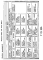
resulting in an enormous sum of expenses.
-
It is, accordingly, an object of the present
invention to overcome the problem in item (1) by
providing a business support system, a business
support method, and a business support data recording
medium which realize a computer with a large-scale,
high-speed totalizing function. Furthermore, it is
another object of the present invention to provide
a business support system, a business support method,
and a business support data recording medium which are
highly reliable because the data is compensated for by
another computer even if any microcomputer terminal has
failed. In addition, it is still another object of the
present invention to provide a business support system,
a business support method, and a business support data
recording medium which enable the past data to be
stored immediately, even if a new microcomputer is
added to a network.
-
Furthermore, it is an object of the present
invention to overcome the problem in item (2) by
providing a business support system and a business
support recording medium which enable a purchased
computer to be set so that it may be adapted easily
to the company or organization that has been using
computers. It is another object of the present
invention to provide a business support method,
a business support system, and a business support
recording medium which enable the desired process to
be performed on the data by selecting a slip or a form
to be used and just entering data in it without paying
attention to the description of program languages
(e.g., COBOL or FORTRAN). The slips or forms that
accept the data are designed to understand the meaning
or contents of the input data automatically and effect
processing.
-
Furthermore, it is an object of the present
invention to provide a business support system and
a business support recording medium which enable
computers now in use to be set so that they may
be adapted easily even when the company structure
is changed or when the business affairs or the type
of business is changed or added in a company or
organization using the computers.
- (1) The foregoing objects are accomplished by
providing: a business support system comprising
a device which is connected via a network to a device
at the called party and has the same data structure
in its own data storage section as that in the data
storage section of the called party's device, wherein
the device includes transmitting means for transmitting
the updated data and its storage location to the called
party, when the data in its own data storage section is
updated, and receiving means for replacing the data in
its own data storage section with the received data,
when the updated data and its storage location are
received from the called party.
The present invention is characterized in that
blocks of functional models used in business are
selected, various information transmission and
reception structures (worksheets) used in the
functional models are displayed, the information
transmission and reception structures are used as
objects into which data is actually entered, thereby
enabling an information transmission and reception
network for the functional models to be constructed
automatically.
- (2) The foregoing objects are further
accomplished by providing: a business support system
comprising: first display means which has the items
for business functional blocks organized as units in
business and displays a menu for the items of the
business functional blocks by a call operation; second
display means which classifies and has the items of
jobs done in the organizations of the business
functional blocks, the items of jobs being given names
in such a manner that the job names have meanings in
business and suggest their contents and further being
defined as worksheets into which working data is
entered, and which displays a menu for the job items
included in the selected functional block, when any one
of the business functional blocks displayed on the
first display means is selected; third display means
which displays the worksheet corresponding to the item,
when any one of the job items displayed on the second
display means; and interlocking control means which not
only superimposes the input data on the worksheet
displayed on the third display means, but also supplies
the update information to the information transmission
destination included in the worksheet.
-
-
This summary of the invention does not necessarily
describe all necessary features so that the invention
may also be a sub-combination of these described
features.
-
The invention can be more fully understood from
the following detailed description when taken in
conjunction with the accompanying drawings, in which:
- FIG. 1A is an explanatory diagram showing the
basic structure of a cell used in the present
invention;
- FIG. 1B is an explanatory diagram of X-axis
parameters of the cell;
- FIG. 2 is an explanatory diagram of Y-axis
parameters of the cell;
- FIG. 3 is an explanatory diagram of Z-axis
parameters of the cell;
- FIG. 4 is an explanatory diagram showing a sales
slip;
- FIG. 5 is an explanatory diagram showing the
relationship between a data access control cell,
an intelligent data cell, and a display;
- FIG. 6 is another explanatory diagram showing
the relationship between a data access control cell and
an intelligent data cell;
- FIG. 7 is a diagram to help explain the transition
of sales slips;
- FIG. 8 is another diagram to help explain the
transition of sales slips in further detail;
- FIG. 9 is an explanatory diagram of cells in
the direction of the G-axis related to the present
invention;
- FIG. 10 is an explanatory diagram showing
an example of using the data in the direction of
the G-axis;
- FIG. 11 is an explanatory diagram showing the flow
of the procedure for sales work;
- FIG. 12 is an explanatory diagram showing the flow
of the procedure for purchasing work;
- FIG. 13 is an explanatory diagram showing
a computer related to the present invention is
connected to a network;
- FIG. 14 is an explanatory diagram showing the
important part of the internal configuration of the
computer related to the present invention;
- FIG. 15 is a flowchart to help explain an example
of the data transmitting process in communication means
related to the system of the present invention;
- FIG. 16 is a flowchart to help explain an example
of the receiving process in the communication means;
- FIG. 17 shows another embodiment of the method of
gathering sales slips;
- FIG. 18 shows cells related to the present
invention arranged in the direction of the G-axis,
helping explain another example of using the system of
the present invention;
- FIG. 19 shows a control section for cells related
to the present invention, helping explain the operation
of the control section;
- FIG. 20 is an explanatory diagram showing the
flow of initial setting the user does when purchasing
a computer terminal related to the present invention;
- FIGS. 21A and 21B show examples of display screens
in forming an employees' ledger on a computer terminal
related to the present invention;
- FIG. 22 shows an example of a display screen in
forming a detailed statement of salary on the computer
terminal related to the present invention;
- FIG. 23 is an explanatory diagram showing
an example of the data structure of the employees'
ledger on the computer terminal according to the
present invention;
- FIG. 24 is an explanatory diagram to help
explain an example of the operation of correlating
the employees' ledger with the detailed statement
of salary on the computer terminal according to
the present invention;
- FIG. 25 is an explanatory diagram showing
an example of the data structure of the detailed
statement of salary on the computer terminal according
to the present invention;
- FIG. 26 is an explanatory diagram showing
an example of the data structure of a salary ledger
for each employee in accounting on the computer
terminal according to the present invention;
- FIG. 27 is a diagram to help explain an example of
the procedure for processing salary-paid slips on the
computer terminal according to the present invention;
- FIGS. 28A and 28B are explanatory diagrams
showing examples of the data structure of the sales
department's ledger on the computer terminal according
to the present invention;
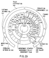
- FIG. 29 is a diagram showing a system of business
functional blocks used in the business support system
according to the present invention;
- FIGS. 30A and 30B show the contents of each
business functional block and examples of slips used in
the functional blocks in the system of FIG. 29;
- FIG. 31 further shows the remaining part of
FIG. 30B;
- FIG. 32 shows the basic concept of the business
support system according to the present invention;
- FIG. 33 is a flowchart to help explain the
operation of effecting initial setting in the business
support system according to the present invention;
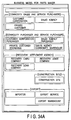
- FIGS. 34A, 34B and 34C show an example of a
business functional block appearing on the menu screen
in the business support system according to the present
invention;
- FIGS. 35A and 35B show a screen appearing when an
intelligent management model of the functional block
shown in FIGS. 34A, 34B and 34C has been selected;
- FIGS. 36A and 36B show a screen appearing when the
factory management panel of FIGS. 35A and 35B is
selected and opened;
- FIG. 37 shows a screen appearing when the
production line panel of FIGS. 35A and 35B is selected
and opened;
- FIGS. 38A and 38B show a screen appearing when the
store management panel of FIGS. 35A and 35B is selected
and opened;
- FIG. 39 shows a screen appearing when the store
food processing panel of FIGS. 35A and 35B is selected
and opened;
- FIG. 40 shows a screen appearing when the
corporate group management panel of FIGS. 35A and 35B
is selected and opened;
- FIG. 41 shows an example of various types of slips
displayed when the item ORDERS RECEIVED in FIGS. 35A
and 35B is selected;
- FIG. 42 shows an example of various types of slips
displayed when the item ORDER PLACED in FIGS. 35A
and 35B is selected;
- FIG. 43 shows an example of various types of slips
displayed when the item GOODS IN STOCK in FIGS. 35A
and 35B is selected;
- FIG. 44 shows an example of various types of slips
displayed when the item FINANCE in FIGS. 34A, 34B
and 34C is selected;
- FIG. 45 shows an example of various types of slips
displayed when the item ACCOUNTING in FIGS. 34A, 34B
and 34C is selected; and
- FIG. 46 shows an example of various types of slips
displayed when the item CONSOLIDATED MANAGEMENT in
FIG. 34A, 34B and 34C or 40 is selected.
-
-
Hereinafter, referring to the accompanying
drawings, embodiments of the present invention will be
explained.
- (1) A business support system of the present
invention is capable of immediately displaying the
total sales for each person in charge, the total sales
for each section, the total sales for each department,
the total sales for each branch office, and the total
sales for the company.
- (2) A business support system of the present
invention is capable of immediately displaying the
total sales for each person in charge by commodity, the
total sales for each section by commodity, the total
sales for each department by commodity, the total sales
for each branch office by commodity, and the total
sales for the company by commodity.
- (3) A business support system of the present
invention is capable of immediately displaying the
total orders placed or received for each person in
charge, the total orders placed or received for each
section, the total orders placed or received for each
department, the total orders placed or received for
each branch office, and the total orders placed or
received for the company.
- (4) A business support system of the present
invention is capable of immediately displaying the
total orders placed or received for each person in
charge by commodity, the total orders placed or
received for each section by commodity, the total
orders placed or received for each department by
commodity, the total orders placed or received for each
branch office by commodity, and the total orders placed
or received for the company by commodity.
- (5) A business support system of the present
invention is capable of immediately displaying the
total recovery (including amount recoverable and amount
recovered) for each person in charge, the total
recovery (including amount recoverable and amount
recovered) for each section, the total recovery
(including amount recoverable and amount recovered) for
each department, the total recovery (including amount
recoverable and amount recovered) for each branch
office, and the total recovery (including amount
recoverable and amount recovered) for the company.
- (6) A business support system of the present
invention is capable of immediately displaying the
recovery (including amount recoverable and amount
recovered) for each person in charge by commodity,
the recovery (including amount recoverable and amount
recovered) for each section by commodity, the recovery
(including amount recoverable and amount recovered) for
each department by commodity, the recovery (including
amount recoverable and amount recovered) for each
branch office by commodity, and the recovery (including
amount recoverable and amount recovered) for the
company by commodity.
- (7) A business support system of the present
invention is capable of immediately displaying the
recovery (including amount recoverable and amount
recovered) for each person in charge by customer,
the recovery (including amount recoverable and amount
recovered) for each section by customer, the recovery
(including amount recoverable and amount recovered) for
each department by customer, the recovery (including
amount recoverable and amount recovered) for each
branch office by customer, and the recovery (including
amount recoverable and amount recovered) for the
company by customer.
- (8) A business support system of the present
invention is capable of immediately displaying the
total accounts receivable for each person in charge,
the total accounts receivable for each section,
the total accounts receivable for each department,
the total accounts receivable for each branch office,
and the total accounts receivable for the company.
- (9) A business support system of the present
invention is capable of immediately displaying the
total accounts receivable for each person in charge by
commodity, the total accounts receivable for each
section by commodity, the total accounts receivable
for each department by commodity, the total accounts
receivable for each branch office by commodity, and the
total accounts receivable for the company by commodity.
- (10) A business support system of the present
invention is capable of immediately displaying the
total accounts receivable for each person in charge
by customer, the total accounts receivable for each
section by customer, the total accounts receivable for
each department by customer, the total accounts
receivable for each branch office by customer, and the
total accounts receivable for the company by customer.
- (11) A business support system of the present
invention is capable of immediately displaying the
balance sheet for each person in charge, the balance
sheet for each section, the balance sheet for each
department, the balance sheet for each branch office,
and the balance sheet for the company.
- (12) A business support system of the present
invention is capable of immediately displaying
the total sales quantity for each person in charge,
the total sales quantity for each section, the total
sales quantity for each department, the total sales
quantity for each branch office, and the total sales
quantity for the company.
- (13) A business support system of the present
invention is capable of immediately displaying the
sales quantity for each person in charge by commodity,
the sales quantity for each section by commodity, the
sales quantity for each department by commodity, the
sales quantity for each branch office by commodity, and
the sales quantity for the company by commodity.
- (14) A business support system of the present
invention is capable of immediately displaying the
sales quantity for each person in charge by customer,
the sales quantity for each section by customer, the
sales quantity for each department by customer, the
sales quantity for each branch office by customer, and
the sales quantity for the company by customer.
- (15) A business support system of the present
invention is capable of immediately displaying
information on the goods in stock for each section,
information on the goods in stock for each department,
information on the goods in stock for each branch
office, and information on the goods in stock for the
company.
What has been described above shows typical
examples. A business support system of the present
invention has useful functions to make various data
analysis and judge the business performance and the
future situation.
- (16) In a case where the computer system is
initialized after a computer or a recording medium
according to the present invention is purchased, the
computer or the recording medium can be adapted easily
to the management structure or company structure the
user has desired. The adapting work is done by just
selecting the one the user needs from the items
appearing on the menu screen and actually entering the
data into worksheets (slits, forms, or ledgers).
- (17) Use of an system of the present invention
facilitates data transfer and exchange between the
computer each user owns and the computer another user
owns, which speeds up the process of placing and
receiving orders between branch offices or between
companies. This is because the entire system of the
present invention is constructed as shown in the
following items (a) to (e): (a) items for functional
blocks organized as units in business have been
classified beforehand; (b) items for jobs done in
each of the organizations of the functional blocks
have been classified beforehand; (c) the item names for
the jobs have meanings in business and are classified
so as to suggest the contents of each job; (d) the
corresponding item is defined as a worksheet into which
working data is to be entered; and (e) the above
classifications are designed to shared by all the
terminals.
-
-
FIG. 1A shows a cell having the basic data
structure of the present invention. The cell is
a data access control cell. Although various types
of cells are defined in the present invention, one
representative cell will be explained.
-
In FIG. 1A, the data access control cell is a cell
for slips. Using three axes, a data cell explained
later can be accessed.
-
By setting parameters on the X-axis and Y-axis,
the slip stored in the address determined by the
parameters can be determined. For example, the slip
for the goods person c in charge in department b of
company a sold in town d can be displayed.
-
Specifically, as shown in FIG. 1B, when the user
wants to see the contents of the desired slip or table
in the above data structure, he or she has only to
give parameters on the X-axis, Y-axis, and Z-axis and
a parameter on the G-axis. The parameter on the G-axis
will be explained later.
X-axis parameter = X (x1 (), x2 (), x3 (), ...) Y-axis parameter = Y (y1 (), y2 (), y3 (), ...) Z-axis parameter = Z (z1 (), z2 (), z3 (), ...) G-axis parameter = G (... -g2 (), -g1 (), g0(),
+g1(), +g2(), ...)
-
When parameter x0 is given in the X-axis
parameters, a table for areas (including North America,
South America, Asia, Europe, and Australia) appears
on the display. When a specifying number is entered
into () in parameter x1 (), this determines an area.
Then, the table for countries in the area (e.g., Asia)
appears on the display. Entering a specifying number
into () in parameter x2 () determines a country.
When a specifying number is entered into () in x3 ()
determines a state. Similarly, entering suitable
specifying numbers into parentheses until a town has
been determined.
-
To stop at the specification of a country, for
example, 0 is entered into () in x3 () and in the later
parameters. Alternatively, the operation of X-axis
specification OK causes the selected state at that time
to remain unchanged.
-
When y0 is entered in the Y-axis parameters, y1 ()
level classification table (company, association,
group) table is displayed as shown in FIG. 2. Then,
entering a number or the like into () in y1 ()
determines a company, association, or group. If a
company is specified, the user's own company/other
company classification table will be displayed at y2()
level of hierarchy. Here, entering a number or the
like into () in y2 () determines either the user's
own company or another company. Then, the head
office/branch office classification table or
the branch office classification table is displayed
at y3 () level of hierarchy. If the head office is
selected, control will proceed to y4 () level of
hierarchy and the department classification table
is displayed. Entering a specifying number into ()
in y4 () determines a department. Similarly, entering
specifying numbers into the parentheses in y5 (),
y6 (), and y7 () determines a person in charge.
-
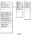
When z0 is given in the Z-axis parameters,
the types of worksheet (e.g., slip) are displayed
as shown in FIG. 3. The worksheet includes various
types of slips, totaling sheets and analizing sheets.
In the present invention, filling-in sheets used in
business, including various types of slips, ledgers,
and forms, and tables, are referred to as worksheets.
Here, writing a slip code into () in z1() level of
hierarchy determines the type of slip and writing
a commodity code into () in z2 () determines the type
of slip for a specific commodity. In this state, for
example, if the specified slip is a sales slip and the
commodity is commodity A for sale, the sales quantity,
unit price, and others will be displayed. In this
case, if the X-axis and Y-axis parameters were given,
the sales slip for commodity α could be displayed on
an area basis or a person-in-charge basis.
-
Not only is a commodity determined, but also
a customer at z3 () level of hierarchy can be
specified. By the specification, for example, it
is possible to display to what company and how many
units of commodity α the person in charge A1 sold.
More than one type of commodity can be determined.
-
In the Z-axis, a commodity selecting parameter
may be specified first and then a slip parameter be
specified.
-
The above hierarchical structure is used in
entering the data when the person in charge sold
a commodity. For example, when the person in charge
sold a commodity and specified the commodity, the slip
table used for the commodity is displayed. When the
commodity was sold, the sales slip, order-received
slip, amount recoverable slip, sales quantity slip, or
the like is selected.
-
When a checkmark is written in () in the G-axis
parameter, the period of time is specified.
For example, entering a checkmark into () in each
of -g2 (), -g1 (), and g0 () specifies from two days
ago to today. Entering a checkmark into () in g0 ()
specifies only today. Entering a checkmark into () in
+g3 () specifies a check on the state of the data only
three days later. An example of using the G-axis
parameters will be explained later.
-
The system of the present invention has the
above-described data structure and is designed to be
able to perform sequential transmission and reception
of common data between the head store and a branch
store, between the main office and a branch office,
or between the main office and each company in
the group. The transmission and reception will be
described later.
-
The information the data access control cell has
includes various addresses. By the address, the real
data stored in another data cell can be specified.
In addition, real data can be written into another
data cell specified by the address.
-
The reason why the control cell is constructed
using the address information is that such a
construction makes the entire memory size smaller.
As can be seen from the explanation of the present
invention, the control cell can function as an active
header. This is because the control cell includes the
address for an update flag explained later and the
transmission destination address for the update flag.
In a case where many microcomputers employ the method
of the present invention, even when only the control
cell is taken out from one computer and used in another
computer, the real data in another computer can be
accessed. The transmission of the address for the
control cell through communication means enables the
real data in the user's computer located at a distant
place to be accessed.
-
Information on slips used in the present invention
enables a date totalizing function to be achieved in
the present system. This not only enables consolidated
settlement between an affiliated company and the head
office or between branch offices but also provides
the user with business support.
-
FIG. 4 shows a case where a person in charge
sold good and entered the data into a worksheet
(e.g., a sales slip). FIG. 4 shows a sales slip.
For example, by giving a Z-axis parameter, a selection
is made from the slip table of FIG. 3. The selected
slip is displayed on the screen, with the items to
be filled in being blank. When the person in charge
is specified using a Y-axis parameter, the name of
the person in charge is displayed automatically in
the person-in-charge field.
-
The sales slip is usually used on the day of sale.
Thus, the date on that day is written automatically in
the sales day. The person in charge enters the code
for a customer (customer code) or an individual
customer indefinite code if the purchaser is an
unregistered individual customer. Then, when the
commodity code for the sold commodity, the quantity,
and the unit price are entered, the sum total of money
is displayed.
-
Here, whether money was received is set.
When money has been received on that day, the mark YES
is checked and the data input is ended. When money has
not been received, a scheduled recovery day is entered.
When payment has been made by credit card, its number
is entered. To acknowledge the input data, OK is
clicked. Moreover, more than one commodity was sold,
the slip on the next page is displayed.
-
The data inputted as described above is stored in
an intelligent data cell explained later.
-
FIG. 5 shows the relationship between the
above-described data access control cell 1000,
an intelligent data cell 2000, a cell control
section 3000, a display section 4000, and an operator
section 5000. The display section 4000 is controlled
via a display control section, which is omitted in
the figure.
-
In the data access control cell 1000, when X, Y,
and Z parameters are specified, a slip as shown in
FIG. 4 appears on the display and enables data about
sales work to be inputted. A sales slip of FIG. 4 will
be explained as a representative example. The screen
that allows parameters on the X-, Y-, Z-, and G-axes
to be entered is caused to appear on the display 4000.
From this screen, parameters are entered, thereby
supplying the parameters to the control cell 1000 via
the cell control section 3000. Then, the control
section 1000 specifies the read address in the
intelligent data cell 2000 via the cell control
section 3000. As a result, the slip screen for
the input of the specified data appears on the
display 4000. Here, the user operates the keyboard in
the operator section 5000, writes the necessary data
into the slip, and finishes the action. Then, the
written data is written into the intelligent data cell
via the cell control section 3000.
-
The intelligent data cell 2000 includes a region
2001 in which the slip layout image data is stored
and a region in which such data items as values and
characters to be written in the blank spaces of the
slip are stored. The control cell 1000 generates
data items that also serve as read addresses in the
intelligent data cell 2000.
-
FIGS. 6 and 7 show an internal processing function
provided in the control cell.
-
Now, it is assumed that a person in charge has
entered the sales information into a sales slip as
explained in FIG. 4. Then, the sales information is
treated as section data, department data, division
data, and company data in sequence. Thus, as shown in
FIG. 6, the sales slip is accompanied by the address
for storing the amount of money (MT) indicating the
total sales, the address for storing the quantity (NT)
indicating the total sales, the address for storing
the unit price, the address for storing computing
expressions, the address for storing the amount of
money (Ms) indicating the amount of money the person in
charge entered when selling the commodity, the address
for storing the quantity (Ns) showing the quantity the
person in charge entered when selling the commodities,
the address for storing the update flag, and the
address for the transmission destination to which the
update flag is to be transferred. These real data
items are stored in the intelligent data cell as
explained in FIG. 5.
-
Now, when the person in charge has entered the
amount of money (Ms) and the quantity (Ns) and operates
OK on the screen of FIG. 4, the update flag is set to,
for example, "1". Then, the following calculations are
performed on the amount of money (MT) and quantity (NT)
using specified computing expressions: MT ← MT + Ms and
NT ← NT + Ns. In this way, the updating process is
carried out. After the updating process, the real data
in the update flag, amount of money (Ms), and quantity
(Ns) are cleared. Then, the update flag is written in
the transmission destination (address) previously set.
-
The control cell 1000 reads the update flag
periodically and, when the update flag is set to "1",
it updates the data as described above.
-
FIG. 7 shows the relationship between the above-described
update flag and the destination to which the
update flag is transferred.
-
Now, it is assumed that four persons in charge A,
B, C, and D (in the same section) sold commodities α
and β and entered data into sales slips. Then, the
destinations to which the update flag for each of the
persons in charge A, B, C, and D are the section's
sales slip 1011, the section's sales slips 1021, 1031
by commodity, and the section's inventory management
slips (ledgers) 1041, 1051. Thus, in the section's
sales slip, the amount of money (MT) from each person
in charge is recognized as the amount of money (Ms) and
the section's sales (MT) are created. In the section's
sales slip 1011, the address for the department's
sales slip is written as the transmission destination.
Thus, in the department's sales slip 1012, the amount
of money (MT) from each section is recognized as the
amount of money (Ms) and the department's sales (MT)
are created (MT ← MT + Ms). Similarly, in the
company's sales slip 1013, the amount of money (MT)
from each department is recognized as the amount
of money (Ms) and the company's sales (MT) are created
(MT ← MT + Ms).
-
In the sales slip by customer, too, an updating
process as described above is carried out.
-
The route of slips 1021, 1022, 1023 is related
to sales slips for commodity α and creates sales
information for each section, for each department,
and for each company automatically. The route of
slips 1031, 1032, 1033 is related to sales slips for
commodity β and creates sales information for each
section, for each department, and for each company
automatically. The route of slips 1041, 1042, 1043 is
related to inventory management slips for commodity α
and creates inventory management information for each
section, for each department, and for each company
automatically. The route of slips 1051, 1052, 1053 is
related to inventory management slips for commodity β
and creates inventory management information for each
section, for each department, and for each company
automatically.
-
A given computing expression is selected,
depending on whether the data input mode or the
correction mode is on. In the correction mode, for
example, a subtracting process or an adding process is
carried out, depending on the contents to be corrected.
In FIG. 6, although computing expressions (1) and (2)
are shown as examples, more computing expressions or
checking processes may be used. As the number of
transmission destinations increases, the update flags
are increased in number accordingly.
FIG. 8 shows the route of sales slips 1011 and
1021 in further detail. When the person in charge has
entered data into a sales slip, the information is
transmitted to the section's sales slip. In the
section's sales slip 1011, storage locations for the
amount of money (Ms) are provided for the individual
persons in charge A, B, C, and D. In addition,
locations for the quantity (Ns) are provided for the
persons in charge A, B, C, and D. Moreover, locations
for the update flag are provided for the persons in
charge A, B, C, and D.
-
In a control operation concerning the section's
sales slip 1011, a check is made periodically to see
if the update flag is set to "1". If the update
flag is set to "1", this means that the amount of
money (MT) and quantity (NT) for the person in charge
corresponding to the update flag "1" have changed.
Thus, the following calculations are done: MT ← MT + Ms
for the corresponding person in charge and NT ← NT + Ns
for the corresponding person in charge. Then, the
update flag for the person in charge is changed from
"1" to "0". For example, if the update flag related
to the sales for person A in charge is set to "1",
the following calculation is done: MT ← MT + (Ms)A.
If the update flag related to the sales for more than
one person in charge, for example, person B in charge
and person C in charge, is set to "1", the following
calculation is done: MT ← MT + (Ms)B + (Ms)C.
-
After the section's sales slip 1011 has been
updated as described above, the update flag "1"
is transferred to the update flag transmission
destination. Then, in the department's sales slip
1012, the amount of money (MT) and quantity (NT) are
updated. The updated information is transmitted to
the company's sales slip.
-
In the route of sales slips 1021, 1022, 1023 for
commodity α, too, sales information for each section,
that for each department, and that for each company
are created automatically. In the route of sales
slips 1031, 1032, 1033 for commodity β, too, sales
information for each section, that for each department,
and that for each company are created automatically.
-
In the route for inventory management slips,
a different computing expression is used. In the
sales slip, the amount of money (MT) is the result of
totalizing the amount of money (Ms). In inventory
management, the following computing expression is used:
NT (updated stock) ← NT (existing stock) - Ns (sales
quantity).
-
Although examples of sales and inventory
management have been explained, the system is provided
with various types of slips and further allows addition
of other various types of slips according to the rules
explained above.
-
With a method conforming to the above-described
rules, recovery slip information for each section, that
for each department, and that for each company are
created immediately. In addition, with a method
conforming to the above-described rules, voucher
information for each section, that for each department,
and that for each company are created immediately.
-
It is easy to create a balance sheet for each
section, that for each department, or that for each
company making use of the amount of money in the
recovery slip and that in the voucher. Therefore, in
the direction of the Z-axis in the present invention,
balance sheet information is arranged.
-
Next, information in the direction of the G-axis
and a method of using the information will be
explained.
-
As shown in FIG. 9, sets of a data access control
cell and an intelligent data cell shown in FIG. 5
are provided on a day-by-day basis as shown in FIG. 9.
For example, g0 () means the cell on that day, -g1 ()
means the cell on the preceding day, -g2 () means the
cell on the day before the preceding day, +g () means
the cell on the following day, and +g2 () means the
cell on the day after the following day. Actually in
the real system, cells for one year or several years
are provided on a day-by-day basis.
-
The time when the contents of the data in each
cell are fixed as information for one day may be
determined in the world reference time. Alternatively,
it may be set to any time in each country or each area
and the contents of the data in each cell be fixed as
information for one day.
-
Referring to FIG. 10, a case where an amount
recoverable slip (information) is created when
commodities α and β were sold will be explained.
If commodity α is sold and its scheduled recovery
data is, for example, March 15, the commodity, person
in charge, and purchaser, together with the amount of
money to be collected, are written into the amount
recoverable slip of the cell of March 15. In addition,
the slip number and others are written as the check
items for March 15 in the recovery check table.
-
When March 15 has been reached, the amount of
money in the amount recoverable slip is read on the
basis of the recovery check table and it is judged
whether the corresponding amount recovered slip (amount
of money) is present. If the corresponding amount
recovered is present, the amount-of-money information
is written into a receipt slip. Then, the check item
for the slip number is cleared from the recovery check
table. It is assumed that commodity β is sold and
the scheduled recovery day for the selling price is,
for example, March 20. When March 20 has been reached,
the amount of money in the amount recoverable slip is
read on the basis of the recovery check table and it is
judged whether the corresponding amount recovered slip
(amount of money) is present. If the corresponding
amount recovered slip (amount of money) is absent, a
bill for the bill issuing table is issued, a scheduled
recovery day (for example, April 10) for the selling
price for commodity β is set again, and its slip number
is written into the recovery check table.
-
When April 10 has been reached, the amount
recoverable slip is collated with the amount recovered
slip as described above. When the amount recovered
slip is absent several times in succession (the bill
has not been paid), the relevant slip and customer list
are printed out.
-
As shown in FIGS. 7 and 8, the amount recoverable
slips for each day are accumulated, calculating the
total amount of money for each department and that
for each company. What is still unpaid is gathered
into an accounts receivable slip, thereby calculating
the total amount of money.
-
The daily totalizing slips are as follows.
-
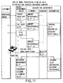
FIG. 11 shows the slip processing flow in sales
work. When receiving an order from a customer, the
person in charge in the sales department enters data
items, including the commodity code and received
order organization code, into an order received slip.
As a result of this, data is inputted to the delivery
slip and claim slip corresponding to the order received
slip. On the other hand, in the slips belonging to
the finance department in the accounting division,
data is inputted to the amount recoverable slip (1)
corresponding to the order received slip and the amount
recoverable slip (2) corresponding to the scheduled
delivery slip. Moreover, data is also inputted to
the amount recoverable slip (3) corresponding to
the claim slip. When issuing the corresponding order
received slip, delivery slip, and claim slip, the
person in charge enters the scheduled recovery date
into the amount recoverable slips (1), (2), and (3).
The commodity code, quantity, unit price, amount of
money, and others to be written in the amount
recoverable slips (1), (2), and (3) have been
transferred automatically when the order received
slip, delivery slip, and claim slip have been issued.
When the customer has made payment after the issue of
the claim slip, the data is written in the receipt slip
in the cashier department. When data is inputted to
the receipt slip, collation is made in the recovery
management slip. If the receipt is correct, an amount
recovered slip is issued. On the journal slip in
the accounting department, the recovery of accounts
receivable is added up. Moreover, in the accounting
department, the accounts receivable are added up on
the journal slip when the preceding amount recoverable
slip (2) is issued.
-
When the data is inputted, the above slip is
subjected to the totalizing process every day as
described above. The commodity code, the code for the
person in charge, the organization code, the customer
code, and others correspond to the slip.
-
FIG. 12 shows the slip processing flow in sales
work. While FIG. 11 shows an example of receiving
an order, FIG. 12 shows an example of placing an order.
The purchasing department issues an ordering slip.
An accounts payable slip (1) corresponding to the
ordering slip is issued under the control of the
finance department. Next, the purchasing department
issues a receiving slip corresponding to the ordering
slip. This slip is such a slip as is issued when
the supplier has answered that the commodity is in
stock after the order was placed. An accounts payable
slip (2) corresponding to the receiving slip is issued
under the control of the finance department. After the
supplier has issued a statement of delivery and a bill,
the purchasing department issues a purchase claim slip.
Since payment must be made, the purchasing department
issues a payment acknowledged slip. In addition, the
finance department issues an accounts payable slip (3)
corresponding to the purchase claim slip. Next, the
finance department issues a payment specifying slip.
In response to this, the cashier department issues
a payment slip, thereby actually paying money into
the bank, paying by draft, or paying in cash.
-
When the data is inputted, the above slip is
subjected to the totalizing process every day as
described above. The commodity code, the code for the
person in charge, the organization code, the customer
code, and others are included in the header of
the slip.
-
It should be noted that the information in the
slip subjected to the totalizing process includes the
date information on that day and days in the future.
That is, information on a different day from that day
on which the data was processed might be written in the
accounts payable slip, payment slip, amount recoverable
slip, and receipt slip, and others.
-
With the system of the present invention, when the
scheduled payment day and scheduled recovery day have
been written in the slips, the slip data items are
stored in the data storage locations in the cell
allocated to the scheduled days. For example, when
the scheduled payment day is today, the slip data is
stored in the cell (see FIG. 9) of parameter g0 ()
on the G-axis. When the scheduled recovery day is
tomorrow, the slip data is stored in the cell (see
FIG. 9) of parameter g1 () on the G-axis.
-
In the system of the present invention, business
support involving the above-described totalizing
process, merchandise management, and various data
management is interlocked through a network in such
a manner that it overcomes the time barrier, regional
barrier, and language barrier.
-
FIG. 13 schematically shows a case where a system
of the present invention is constructed, taking
domestic areas and overseas areas into account.
A microcomputer 5001 at the head office at home,
a microcomputer 5002 at a branch office in a domestic
area, a microcomputer 5003 at a branch office in
foreign country 1, and a microcomputer 5004 at a branch
office in foreign country 2 are connected to each other
via a network 6000 and a communication interface.
-
FIG. 14 shows the basic configuration of the
microcomputer.
-
Numeral 103 indicates a hardware system control
section, where a CPU 111, a ROM 112, and a RAM 113 are
connected via a bus 114. The operator section 5000 and
a disk driver 115 are also connected to the bus 114.
-
In the ROM 112, a program serving as an operating
system (OS) that controls the basic operation of the
control section 113 is written. The CPU 111 exchanges
instructions with the ROM 112 and performs operation on
the basis of the operating system. The RAM 113 is used
as work memory for storing data temporarily.
-
The bus 114 is connected to a bus 212 via
a bus 211. To the bus 212, functional blocks the
present invention features are connected. A display
4000 is also connected via a display interface 121 to
the bus 212.
-
The bus 212 is further connected to a network via
a transmission/reception interface 122. Various types
of network, including a public telephone network, the
Internet, and an intranet, can be used.
-
The image and data appearing on the display 4000
is controlled by a display control section 213.
The data taken in via a transmission/reception
interface 122 is loaded into and stored temporarily
in a receiving section 214. The data loaded into
the receiving section 214 is converted in data
format by a data format conversion section 215,
if necessary. The converted data is stored in
the receiving section 214.
-
The data stored in a transmitting section 216
is sent via the transmission/reception interface 122
to the network. In this case, the transmitted
data includes the telephone number specifying
the called party and the identification number (ID).
The transmitted data is further scrambled and
transmitted. Depending on the called party, the data
format of the transmitted data might be converted by
the data format converting section 215. The reason for
this is that the data format of the computer at the
called party might differ from the data format of the
present system at the calling party.
-
The data format converting section 215 has the
function of converting item names of the received
data, if necessary. This function is needed for the
following reasons: for example, when the customer has
sent a voucher for the commodity, it is a recovery slip
on the reception side; moreover, when the customer has
sent a sales claim slip, it corresponds to a purchase
claim slip on the reception side; additionally, when
the customer has sent an order placed slip, it is
an order received slip on the reception side. These
conversions belong to the function of converting slip
item names.
-
The data format converting section 215 further
includes a language conversion dictionary for
translating business terms in various languages and
the function of converting the currency unit.
-
Therefore, the item names in a slip appearing on
the screen are prepared in various languages. When the
cell is received, the item names of the corresponding
slip can be converted by the language conversion
dictionary into the language the user desires.
-
The cell control section 3000 as shown in FIG. 4
and a cell file 7000 in which cell groups are stored
are connected to the bus 212.
-
In the business support system of the present
invention, all the microcomputers basically have the
same data.
-
Thus, the sales information as explained in
FIGS. 7 and 8 are constructed not only in the cells in
the same computer but also in the cells in all the
other computers that transmit and receive the data to
and from each other.
-
To do this, the transmitting section 216 functions
at the time when the updating process has finished.
-
In addition, a system setting control section 8000
used to do initial setting in the whole system and
correct a function is connected to the bus 212.
-
Hereinafter, the function of the transmitting
section 216 will be described by reference to FIG. 15.
The transmitting section 216 includes a list of
transmission destinations and a transmission memory.
When the updating process has been carried out, the
cell control section 3000 reports that the updating
process has been performed (steps A1, A2). Then, the
transmitting section 216 determines the transmission
destination from the list of transmission destinations
(step A3) and temporarily copies the X-, Y-, Z-, and
G-axis parameters to be transmitted (the parameters
specifying each slip explained in FIGS. 7 and 8) and
the intelligent data corresponding to the slip into the
transmission memory (step A4). Then, the transmitting
section 216 converts those data items into transmission
data (serial) and calls the transmission destination
(steps A5, A6). The transmission destination is called
using the telephone number or password on the basis
of the rules of the network. When the reception
enable response is received from the transmission
destination, the transmitting section transmits
the data (steps A7, A8). After the transmission,
the transmitting section clears the transmission memory
and ends the process (step A9).
-
FIG. 16 shows the function of the receiving
section 214 when the intelligent data has been received
as described above. When there is a call from the
called party and the called party has been registered
as one of the callers, the receiving section 214
sends a reception enable response (steps B1, B2, B3).
After sending the response, then the called party sends
the data. The receiving section 214 then loads the
data temporarily into the reception memory (step B4).
Next, the receiving section 214 judges whether the
received data is the intelligent data (step B5). If it
is the intelligent data, the receiving section 214
replaces the data in the intelligent data cell in the
cell file 7000 with the received intelligent data,
making use of the received X-, Y-, Z-, and G-axis
parameters (the parameters specifying each slip in
FIGS. 7 and 8) (step B6). This makes the sales
information and stock information resulting from the
sale of commodities by persons in charge A, B, C, and D
all the same in any computer.
-
With the system of the present invention, the
receiving process is carried out each time the
reception data arrives, and the data is updated.
The time when transmission is made can be determined
arbitrarily according to the transmission rule and
is determined at the transmitting section. It is
possible to specify the receiving party and prevent the
data from an unspecified device from being received.
It is also possible to specify the called party and
transfer the data only to the specified called party.
-
As described above, for example, when the slip
data is updated on the microcomputer at a branch
office, the slip information is transferred to the
microcomputer at the head office by the transmission
method described earlier. Then, the corresponding data
items at the head office are updated. Conversely, when
the slip data is updated on the microcomputer at the
head office, the slip information is transferred to the
microcomputer at a branch office by the transmission
method described earlier. Then, the corresponding data
items at the branch office are updated. In this way,
by sharing the data with plural branch offices, the
data would never be lost, even if any one of the
microcomputers failed. When a microcomputer is added
to the network and shares the data, it receives the
data from another microcomputer by the transmission
method described earlier. With this approach, the
network system of the present invention realizes
a computer with a large-scale, high-speed totalizing
function.
-
As described above, the system of the invention
produces the following business support effects:
- (1) The transmission/reception means connects
between the individual microcomputers, thereby
establishing a network.
- (2) The structure of the business data is based
on a common format.
- (3) The daily totalized data is transmitted to
each microcomputer.
- (4) Because the data structure is classified
hierarchically in the direction of multiple axes, the
data can be analyzed from various angles by giving
parameters to each axis.
- (5) Because cells (blocks with the common data
structure) are arranged in the direction of the time
(date) axis, the data can be analyzed in the direction
of the time axis. Use of the result of the analysis
makes it possible to quickly get judging material in
making a project plan and a financing plan necessary
for business.
-
-
Although each functional block has been
constructed in hardware as shown in FIG. 14 in the
explanation, the data format converting section 215,
transmitting section 214, receiving section 216,
display control section 213, cell control section 3000,
and cell file (data storage section) 7000 may be
recorded on a recording medium (e.g., an optical disk
or a magnetic disk) and the recording medium be
installed in a personal computer, thereby realizing
the above-described functional blocks. Thus, it goes
without saying that the idea of the present invention
also covers the data structure recorded on the
recording medium and the control data for realizing the
above functions.
-
The present invention is not restricted to the
above embodiment.
-
In FIG. 7, when the person in charge has sold
a commodity, the sales information is transmitted to
the section's sales, the department's sales, and the
company's sale simultaneously. The sales information,
however, may be transmitted only to the section level
or the smallest group unit level, instead of being
transferring to the entire organization at the same
time when the commodity was sold. Then, the
department's sales information or the company's sales
information may be gathered by the executives of the
company, if necessary.
-
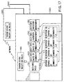
FIG. 17 shows a state where sales information is
gathered on a section basis when commodities were sold.
Now, it is assumed that four persons in charge A, B, C,
and D (in the same section) sold commodities α and β
and entered data into a sales slip. Then, the
destinations to which the update flag for each of the
persons in charge A, B, C, and D are the section's
sales slip 1011, the section's sales slips 1021, 1031
by commodity, and the section's inventory management
slips (ledgers) 1041, 1051. Thus, in the section's
sales slip, the amount of money (MT) from each person
in charge is recognized as the amount of money (Ms) and
the section's sales (MT) are created.
-
In the sales slip by commodity, too, a similar
process to what has been described above is carried
out.
-
The slip 1021 is a sales slip for commodity α
and sales information is created section by section
automatically. The slip 1031 is a sales slip for
commodity β and sales information is created section by
section automatically. The slip 1041 is an inventory
management slip for commodity α and inventory
management information is created section by section
automatically. The slip 1051 is an inventory
management slip for commodity β and inventory
management information is created section by section
automatically.
-
When the information for each section is updated,
information as to whether the updating has been done is
transmitted to a transmission/reception decision
section 1061. The transmission/reception decision
section 1061 is provided in the receiving section 214,
transmitting section 216, or cell control section 3000
in FIG. 4.
-
Now, it is assumed that the computer the persons
in charge A, B, C, and D operate is the microcomputer
5003 at the branch office in foreign country 1 in
FIG. 13. The computer 5003 transmits the updated data
via the network to the microcomputer 5001 at the head
office and the microcomputer 5002 at the branch office.
The data is stored in the corresponding locations
having the identical data structure. As a result,
sales information is constructed in the computer 5001
at the head office in such a manner that it has the
same format as that of the data in the computer 5003 in
foreign country 1. The transmission/reception decision
section 1061 is capable of determining not only
the data to be transmitted to another computer but
also whether to permit the acceptance of the data
transmitted from another computer.
-
The timing with which the daily totalized data is
transmitted to another computer for updating is set in
various ways. For example, when computers are provided
at a first branch office, for example, one of them is
set as the representative computer of the first branch
office. The representative computer is so set that the
remaining computers used at the first branch office
transmit the updated data to the representative
computer chronologically. Namely, at the branch
offices or the head office, the representative computer
gathers the data chronologically.
-
In contrast, between the representative computers
for communication at branch offices and between the
representative computers for communication at the
head office and branch offices, time zones for data
transmission and reception are determined beforehand.
For example, the data is transmitted and received on
a 6-hour basis, a 12-hour basis, or a 24-hour basis.
The computer on the data reception side constructs
a cell for each day of FIG. 9 using a unique reference
(or using local time or the time determined in the
world time as a reference).
-
In the case where sales information for each
section, sales information for each section by
commodity, and inventory management information for
each section are present, when the sales for all the
branches or the sales for the whole company are
required, the user operates the computer. For example,
when the user operates the operator section 5000, opens
the menu screen, and selects and displays the sales
slips for all the branches or for the whole company,
the computing processes as shown in FIGS. 7 and 8 are
carried out automatically, allowing the user to look at
the present sales situation.
-
Furthermore, when the user gives parameters in
the direction of the G-axis to specify the period of
inquiry and further specifies an amount recoverable
slip, it is possible to totalize the amount of money
to be collected written on the amount recoverable slip
for several days. This enables the user to know the
total sum of money to be collected in a few days.
When specifying an accounts receivable slip, the user
can know the total sum of money to be paid in a few
days.
-
While FIG. 18 shows examples of the amount
recoverable for the whole company and the accounts
receivable for the whole company, the present invention
is not limited to these. The amount recoverable by
commodity and the accounts receivable by commodity may
be obtained. Moreover, the amount recoverable for each
department or division and the account receivable for
each department or division may be obtained.
-
The way of displaying the state of the amount
recoverable or accounts receivable in a single company
has been explained.
-
The system of the present invention enables
information (cells) to be transmitted and received
freely to and from an affiliated company or another
company. This makes it possible to perform
a consolidated accounting process in a cooperate
group at high speed.
-
With the system of the present invention, various
types of slips are provided in the direction of the
Z-axis. Related slips are correlated to each other
using the update flag and its transmission destination
information as explained in FIGS. 7 and 8.
-
In a recovery slip, information (payer
information) indicating from which company the money
was collected is written. In a voucher, information
(payee information) indicating which company the money
was paid to is written. As described earlier, the
amount of money collected for the whole company and
the amount of money paid for the whole company can be
obtained using those pieces of information as described
above. Various types of business information about
not only the user's company but also other companies
can be stored in cells having the data structure of
the present invention.
-
For example, a balance sheet, a statement of
profits and losses, and a cash flow sheet can be
created on the microcomputer in each company.
In addition, the daily totalizing file of account
titles and a daily totalizing file of subsidiary
account titles can be created. Moreover, the file
can be created currency by currency since the present
system covers international areas.
-
In a case where there are a parent company and
subsidiary companies, when consolidated accounting is
done, pieces of information, including consolidated
automatic journal slips, consolidation adjustment
journal slips, daily totalization of consolidated
account titles, and daily totalization of consolidated
subsidiary account titles, are transmitted from
a subsidiary company to the parent company on the basis
of the communication rules. Additionally, consolidated
accounting organization information, the beginning
balance of consolidated account titles, and the
beginning balance of consolidated subsidiary account
titles are also transmitted as accounting information
to the parent company.
-
The parent company can create a consolidated
cash flow sheet, a consolidated income statement,
a consolidated balance sheet, and the like on the basis
of the account information from subsidiary companies.
Thus, the companies which have been registered with
each other can carry out a consolidated accounting
process easily and automatically. They can execute it
monthly, semiannually, or annually.
-
The basic idea of the present invention is not
limited to the above embodiment.
-
In the above embodiment, the system that has been
constructed beforehand is used. A computer, however,
has to be constructed when it is purchased by the user
in such a manner that it has the function the user
desires. In a case where the function of a computer is
constructed at the beginning so as to adapt to the
company's business form, a computer system of the
present invention is designed to enable the user to
construct such a function. Even when the company
structure is changed, the computer system is designed
to enable the user to reconstruct the function of the
computer so as to adapt to the new company structure.
-
FIG. 19 shows the relationship between the control
cell 1000, data cell 2000, cell control section 3000,
display section 4000, operator section 5000, and
display control section 213.
-
In the control cell 1000, an address for reading
the data in the data cell 2000 is written. The address
is determined by entering the above-described
parameters on each of the X-, Y-, and Z-axes via
the cell control section 300 from the operator
section 5000. After the address is determined,
the address in the data cell 2000 is specified via the
cell control section 3000 and the image data, character
data, and numeric data are read. These data items are
displayed on the display via the display control
section 213.
-
The image data includes such frame image data as
slips and ledgers. The character data includes such
data as item names, captions, and names for slips or
ledgers. The numeric data includes such data as date,
sales, and the amount paid. In a microcomputer just
purchased, there are such frame data as slips and
ledgers. The numeric data items are written as "0",
because they will be inputted from now on.
-
FIG. 20 shows the process of effecting modeling
(D2) after a computer is purchased (D1), setting
rules for the use of computers or business rules (D3),
and actually using and applying computers (D4)
(or the construction and execution processes).
Modeling means selecting a business function on the
computer so as to adapt to the company structure of the
user who has purchased the computer. Setting rules
means setting various rules, including the scope of
an employee's official authority (e.g., sales authority
or approval authority), the limit of credit given, and
various conditions of customers, after the company
structure is constructed as an electronic organization
on the computer.
-
In the system of the present invention, various
active organizations have been prepared, taking into
account conceivable organizations in the workings of
business (e.g., company management).
-
All the conceivable functions and organizations
are assumed as follows: (1) a case where a company
structure is constructed; (2) a case where the
necessary organization is constructed in business; (3)
a case where a management organization is constructed
for private management; (4) a case where a management
organization is constructed; and (5) a case where a
administrative management organization is constructed.
At the stage where the functions and organizations are
actually used, since some organizations or functions
are unnecessary, depending on the contents of the
business or the activity range of the company, they can
be set so that they may be prevented from being used.
-
Namely, the computer system of the present
invention can be adapted easily to the company by just
selecting the organization and function after the
purchase.
-
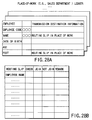
As shown in FIG. 21A, for example, the personnel
structure (Y-axis) of the user's company (X-axis)
and the employees' ledger (Z-axis) can be read and
displayed. Immediately after the purchase, because
the employees' information filling-in field is blank,
it is necessary to enter the company's employees'
information into the field.
-
The input items include code, name, the date of
birth, age, post, place of work, salary, hometown, alma
mater, family structure, special talent, and comment.
-
When there are temporary employees, a temporary
employees' ledger is created in a similar manner as
shown in FIG. 21B. In the case of temporary employees,
information on additional conditions, including working
hours, is added. Some items, including post, hometown,
alma mater, and family structure, are omitted.
-
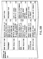
Next, a detailed statement of salary for each of
the employees and temporary employees must be created.
The detailed statements of salary are handled at,
for example, the cashier's office. In such a case,
when specifying and displaying the accounting structure
(Y-axis) of the company (X-axis) and the detailed
statement of salary (Z-axis), the user can deal with
the detailed statements of salary for all the employees
and temporary employees.
-
FIG. 22 shows an example of the detailed
statements of salary displayed on the screen. First,
the frame of the detailed statement of salary appears
and then an employee's code and salary appear. When
the next detailed statement of salary is clicked, then
the following different employee's detailed statement
of salary comes to the front. When the employees'
ledger has been created, each employee's detailed
statement of salary has been prepared automatically on
the basis of each employee's code. Moreover, when each
employee's salary has been written in the employees'
ledger, the amounts of salary have been written in the
detailed statements of salary displayed.
-
The reason for this is that the address and
the transmission destination address have been written
in the control data for displaying the employees'
ledger. The control data is the data stored in the
control cell. Although not shown in the field for
the amount paid into the bank, it is accompanied by
the bank into which salary is to be paid and the number
of an employee's bank account.
-
In FIGS. 21A and 21B, the employees' ledger has
been explained using an example of the screen appearing
on the display in constructing the data. Inside the
control cell, however, the transmission destination
information on the pieces of information written is
attached in such a manner that it is linked with each
field of the ledger.
-
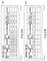
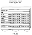
FIG. 23 shows the data structure format for the
whole employees' ledger. FIGS. 21A and 21B show the
display format for the employees' ledger. In the data
structure format, the detailed statement of salary,
place-of-work ledger, and accounting ledger are
specified as the transmission destinations of each
employee's code and name. The transmission destination
of post includes the detailed statement of salary
and place-of-work ledger. The place-of-work
information is so specified that it is transferred
to the place-of-work ledger. Moreover, the salary
information is so specified that it is transferred to
the detailed statement of salary and accounting ledger.
The hometown information is so specified that it is
transferred to a list of persons from the same town.
The alma mater information is so specified that it is
transferred to an alumni association ledger.
-
When the employees' ledger has been created,
as many detailed statements of salary as are equal to
the number of employees are created automatically.
That is, the detailed statements of salary shown
in FIG. 22 are created automatically. At this time,
the employees' codes, names, and salaries are set in
the detailed statements of salary automatically.
Specifically, control data for the detailed statement
of salary is created in the control cell.
-
FIG. 24 shows a processing routine in a case
where data on the detailed statements of salary is
constructed automatically after the whole employees'
ledger has been created. When the setup mode is on
and the whole employees' ledger has been created
(steps E1, E2), the number of employees in the salary
ledger is counted and as many detailed statements of
salary as equal the number of employees are prepared
(step E3). Next, the detailed statement of salary for
each employee is created (E4).
-
Specifically, data on the detailed statement
of salary is created in the control cell as shown
in FIG. 25. Namely, data items (specifically,
the address for the data cell (in the address, data
items, including an employee's code and an employee's
name, have been written)) appearing in the detailed
statement of salary, including employee's code,
employee's name, salary, and allowance, are allocated
to the detailed statement of salary. Furthermore,
transmission destination information is also
incorporated. As for the transmission destination
of each data item written in the detailed statement
of salary, salary, allowance, premium, and others
are transferred to the information part of the
corresponding employee's code in the accounting ledger.
-
Specifically, the same address as that written in
the preceding detailed statement of salary is written
in the fields for the corresponding employee's code and
salary in the accounting ledger control data.
-
FIG. 26 shows an example of a ledger related to
salary at the accounting department. In the ledger,
pieces of information on the salary and allowance for
each employee are written, followed by transmission
destination information for each piece of information.
Since the number of the bank account is incidental to
the amount paid into the bank, the amount paid into the
bank is transmitted to a paying slip for each bank.
-
FIG. 27 briefly shows how the salary paid
information is transmitted at the accounting division.
The amount of salary paid to each employee is
transmitted to a slip that totals the amount of salary
paid in the whole department. The total sum of the
amount of salary paid in the department is transmitted
to a slip that totals the amount of salary paid in the
whole company. Referring to the number of the bank
account, the amount paid into the bank is transmitted
to the bank paying slip.
-
FIG. 28A shows the state where, for example,
the sales department's personnel ledger is created,
with the employees' ledger already created. At the
ledger of an organization to which the employees
belong, information on the whole employees' ledger
is used as it is, accompanied by the transmission
destination information. The transmission destination
information includes a routing slip (FIG. 28B) used
in the organization to which the employees belong.
Information on the name of an employee is transmitted
to the field for employee's name on the routing slip.
-
As described above, the necessary information
about the employees is created and then the
organization to which each employee belongs is set.
After information about the employee's salary is
determined, the information is directed automatically
to the accounting system.
-
FIG. 29 shows a standard model when the company
is organized. In the model, various types of slips are
circulated. As explained earlier, each of them can be
linked with the necessary places.
-
FIG. 29 shows each type of functional model set in
the system of the present invention. To make it easier
to understand, each model is shown, centered on the
idea of company management. Each functional model is
assigned a reference symbol and will be explained
briefly. A functional model 500 is a model at the
personnel and salary department. When the functional
model is turned on, this makes it possible to deal with
data items including a detailed statement of salary and
a letter of appointment used in doing work related to
personnel and salary. The individual functional models
are classified into the contents of work and the work
regulations. Slips handled in the work are allocated
to the items about the contents of work. The limits to
work and agreement on the work are inputted to the work
regulations.
-
The contents of each block in FIG. 29 are shown in
detail in FIGS. 30A, 30B and 31. The same reference
symbols in FIG. 29 are also used in FIGS. 30A, 30B
and 31. As described above, in the system of the
present invention, the functional models necessary in
business (which may be referred to as functional blocks
or functional parts) have been standardized.
-
When the blocks of the functional models are shown
on the screen and the desired block is selected, the
slips, forms, and others (generally called worksheets)
related to the block are displayed. Then, the desired
slip and form are selected, the slip and form become
active in use now. A slip or a form into which no data
is entered is recognized as unused on the computer.
As for the functional models, the relevant model is
selected. As long as no data is entered into the
block, the block is recognized as the block of an used
functional model on the computer. When other related
functional models become active, some functional blocks
become active automatically. For example, as explained
earlier, the worksheets for the functional blocks
related to each other, like the personnel ledger
and the place-of-work ledger, might become active
automatically.
-
Therefore, with the quickly adaptable computer
of the present invention, the user displays the
systematized business functional models on the screen,
selects the block of the desired functional model,
and actually uses the slips and ledgers registered in
the functional block, thereby reflecting the user's
business on the screen automatically.
-
FIG. 32 is a conceptual diagram of what has been
explained above. A business model (of the freely
adaptable type) corresponds to the systematic part
of the functional block explained in FIGS. 30A, 30B
and 31. An application (of the quickly adaptable type)
corresponds to the system controlled by entering the
data into the slips and ledgers explained in FIGS. 1A
to 18. Immediately after a personal computer is
purchased, the user can display the functional blocks
necessary to the company and enter the data into the
slips and ledgers in the necessary blocks, thereby
constructing a computer system suitable for the
company. Company A, company B, ... at right in FIG. 32
show the state after they each have constructed their
own computer systems.
-
The reason why they have succeeded in realizing
such computer systems is that business terms have been
standardized in meanings and contents. That is, as
explained earlier, this is because the data structure
is such that entering the data into the slips and
ledgers determine the contents of the data processing
automatically according to the fields into which the
data is entered.
-
Because the above data process is done in
constructing the system of FIG. 20, that is an example
of adding new pieces of information when pieces of
information are inputted one after another. In company
management, however, employees are transferred to new
positions, their change work of place is changed, or
the company structure is changed. In that case,
the entire system is set in the system modify mode.
Then, the functional block that wants modifications
is selected. The data is entered again into the slips
and forms included in the functional block, thereby
modifying the block. When an unused functional block
appears, all the data items written in the functional
block have only to be made zero or cleared.
-
As described above, the present invention
comprises first display means, second display means,
third display means, and interlocking control means.
The first display means has items for functional blocks
organized as units in business and displays an item
menu for the functional blocks as a result of a call
operation. The items of jobs done in the organizations
of the functional blocks are classified. Names are
given to the jobs in such a manner that the job names
have meanings in business and suggest their contents.
The items are defined as worksheets into which working
data is entered. The second display means has the job
items and displays a menu for the job items included in
the selected functional block, when any one of the
functional blocks displayed on the first display means
is selected. The third display means displays the
worksheet corresponding to the item, when any one of
the job items displayed on the second display means.
The interlocking control means not only superimposes
the input data on the worksheet displayed on the third
display means, but also supplies the update information
to the information transmission destination included in
the worksheet.
-
FIG. 33 shows the operation at the start-up when
initial setting is done in a case where a computer
system of the present invention has been purchased
as a terminal. When the initial setting mode is
turned on, the business modeling function block is
displayed in the form of a menu on the screen (steps F1
and F2). This is done under the control of the system
setting control section 8000 of FIG 14. The functional
block is the outermost functional block shown in
FIG. 29, which includes personnel, salary, accounting,
financial affairs, production control, sales physical
distribution, customer information, marketing, and
networking. When the user selects the desired
functional block (or the functional block possibly
needed for the user's business), the items for
the worksheets (including slips and ledgers)
necessary for various jobs done in the functional
block are displayed in the form of a menu screen
(steps F3 and F4). On the second-stage menu screen,
various slips and forms for jobs and rules are
displayed. Here, the user enters the necessary
data into the desired worksheet. For example,
the above-described employees' ledger or the like is
created. Alternatively, at the sales division,
information on sales authority (e.g., the largest
turnover) is entered for each person in charge
(step F5).
-
As described above, entering the data enables
a company structure to be designed automatically on the
computer. When the busy mode is turned on, the system
is brought into the in-operation state. After using
the system, when the user think that the functional
blocks are insufficient, the user should turn on
the setting mode and select and add functional blocks.
For example, this is a case where a company that
engaged in only sales begins to process parts.
-
After the business initial setting has been done
on the computer as described above, when the busy mode
is turned on, for example, the active functional blocks
are displayed on the screen. This makes it easy for
the user to understand the functions used for work.
-
The present invention is not limited to the above
embodiment, which is representative only for the
explanation of the basic idea.
-
FIGS. 34A, 34B and 34C show an example of a
functional block displayed in the initial setting mode.
-
Now, an intelligent management model is assumed
to have been selected. Then, as shown in FIGS. 35A
and 35B, the model design panel for any one of company
management, factory management, production line, store
management, store food processing, and corporate group
management can be selected.
-
FIGS. 35A and 35B show a state where the company
management panel has been selected and opened.
FIGS. 36A and 36B show a state where the factory
management panel has been selected and opened. FIG. 37
shows a state where the production line panel has been
selected and opened. FIGS. 38A and 38B show a state
where the store management panel has been selected
and opened. FIG. 39 shows a state where the store
food processing panel has been selected and opened.
FIG. 40 shows a state where the corporate group
management panel has been selected and opened.
-
Each panel further has classification items.
When any one of the items is selected, the types of
worksheets used under the item are displayed.
-
FIG. 41 shows an example of various types of slips
displayed when the item "RECEIVING ORDERS FOR GOODS" is
selected under the items of FIGS. 35A and 35B. In this
state, when a slip is selected and the data is entered,
the business items to which the slip belongs become
active.
-
FIG. 42 shows an example of various types of slips
displayed when the item "PLACING ORDERS FOR GOODS" is
selected under the items of FIGS. 35A and 35B. In this
state, when a slip is selected and the data is entered,
the business items to which the slip belongs become
active.
-
FIG. 43 shows an example of various types of slips
displayed when the item "GOODS IN STOCK " is selected
under the items of FIGS. 35A and 35B. In this state,
when a slip is selected and the data is entered, the
business items to which the slip belongs become active.
-
FIG. 44 shows an example of various types of slips
displayed when the item "FINANCE" is selected under the
items of FIGS. 34A, 34B and 34C. In this state, when a
slip is selected and the data is entered, the business
items to which the slip belongs become active.
-
FIG. 45 shows an example of various types of slips
displayed when the item "ACCOUNTING" is selected under
the items of FIGS. 34A, 34B and 34C. In this state,
when a slip is selected and the data is entered, the
business items to which the slip belongs become active.
-
FIG. 46 shows an example of various types of slips
displayed when the item "CONSOLIDATED MANAGEMENT" is
selected under the items of FIG. 34A, 34B and 34C
or 40. In this state, when a slip is selected and the
data is entered, the business items to which the slip
belongs become active.
-
Although in the above explanation, the present
invention has been structured of blocks by means of a
computer system, the control file having the important
function of the invention may, of course, be recorded
on a recording medium (e.g., an optical disk or
a magnetic disk).
-
Specifically, the recording medium includes:
- a first display control file which has the items
for business functional blocks organized as units in
business and displays a menu for the items of the
business functional blocks on a display by a call
operation;
- a second display control file which classifies and
has the items of jobs done in the organizations of the
functional blocks, the items of jobs being given names
in such a manner that the job names have meanings in
business and suggest their contents and further being
defined as worksheets into which working data is
entered, and which displays a menu for the job items
included in the selected functional block, when any one
of the business functional blocks displayed on the
display on the basis of the first display control file
is selected;
- a third display control file which displays the
worksheet corresponding to the item, when any one of
the job items displayed on the display on the basis of
the second display control file; and
- an interlocking control file which not only
superimposes the input data on the worksheet displayed
on the basis of the third display control file, but
also supplies the update information to the information
transmission destination included in the worksheet.
-
-
The application of the present invention is not
limited to the above embodiment. While in the above
explanation, the computer body subjected to initial
setting or the recording medium includes all the
business functional blocks, the information recording
medium may be provided for a provider through
a network.
-
A user who has made a contract may take in the
necessary menu information through the network,
construct a business model as explained in FIGS. 29
to 40, and load the data in the necessary business
block and worksheets into the user's computer.
The system of the present invention has a communication
function and can take in cells. Therefore, by
constructing the functional blocks and various
worksheets in the direction of the Z-axis of the cell,
a unique business model can be obtained and put into
operation.
-
As described above, according to the present
invention, there are provided a business support
system, a business support method, and a business
support data recording medium which realize a computer
with a large-scale, high-speed totalizing function.
Furthermore, according to the present invention, there
are provided a business support system, a business
support method, and a business support data recording
medium which are highly reliable because the data is
compensated for by another computer even if any
microcomputer terminal has failed. In addition, it
is possible to provide a business support system,
a business support method, and a business support data
recording medium which enable the past data to be
stored immediately, even if a new microcomputer is
added to the network.