EP1078601A2 - Lung volume reduction apparatus - Google Patents
Lung volume reduction apparatus Download PDFInfo
- Publication number
- EP1078601A2 EP1078601A2 EP00118072A EP00118072A EP1078601A2 EP 1078601 A2 EP1078601 A2 EP 1078601A2 EP 00118072 A EP00118072 A EP 00118072A EP 00118072 A EP00118072 A EP 00118072A EP 1078601 A2 EP1078601 A2 EP 1078601A2
- Authority
- EP
- European Patent Office
- Prior art keywords
- jacket
- further characterized
- lung
- lung portion
- mandrel
- Prior art date
- Legal status (The legal status is an assumption and is not a legal conclusion. Google has not performed a legal analysis and makes no representation as to the accuracy of the status listed.)
- Granted
Links
- NFWSQSCIDYBUOU-UHFFFAOYSA-N CC1=CC=CC1 Chemical compound CC1=CC=CC1 NFWSQSCIDYBUOU-UHFFFAOYSA-N 0.000 description 1
Images


Classifications
-
- A—HUMAN NECESSITIES
- A61—MEDICAL OR VETERINARY SCIENCE; HYGIENE
- A61B—DIAGNOSIS; SURGERY; IDENTIFICATION
- A61B17/00—Surgical instruments, devices or methods, e.g. tourniquets
- A61B17/00234—Surgical instruments, devices or methods, e.g. tourniquets for minimally invasive surgery
-
- A—HUMAN NECESSITIES
- A61—MEDICAL OR VETERINARY SCIENCE; HYGIENE
- A61B—DIAGNOSIS; SURGERY; IDENTIFICATION
- A61B17/00—Surgical instruments, devices or methods, e.g. tourniquets
- A61B17/12—Surgical instruments, devices or methods, e.g. tourniquets for ligaturing or otherwise compressing tubular parts of the body, e.g. blood vessels, umbilical cord
-
- A—HUMAN NECESSITIES
- A61—MEDICAL OR VETERINARY SCIENCE; HYGIENE
- A61F—FILTERS IMPLANTABLE INTO BLOOD VESSELS; PROSTHESES; DEVICES PROVIDING PATENCY TO, OR PREVENTING COLLAPSING OF, TUBULAR STRUCTURES OF THE BODY, e.g. STENTS; ORTHOPAEDIC, NURSING OR CONTRACEPTIVE DEVICES; FOMENTATION; TREATMENT OR PROTECTION OF EYES OR EARS; BANDAGES, DRESSINGS OR ABSORBENT PADS; FIRST-AID KITS
- A61F2/00—Filters implantable into blood vessels; Prostheses, i.e. artificial substitutes or replacements for parts of the body; Appliances for connecting them with the body; Devices providing patency to, or preventing collapsing of, tubular structures of the body, e.g. stents
- A61F2/0063—Implantable repair or support meshes, e.g. hernia meshes
Definitions
- the present invention is generally directed to an apparatus and method for treating Chronic Obstructive Pulmonary Disease (COPD).
- COPD Chronic Obstructive Pulmonary Disease
- the present invention is more particularly directed to such an apparatus and method which may be implanted in the human body to provide lung size reduction by constricting at least a portion of a lung.
- COPD Chronic Obstructive Pulmonary Disease
- COPD chronic obstructive pulmonary disease
- COPD chronic obstructive pulmonary disease
- Current treatments for COPD include the prevention of further respiratory damage, pharmacotherapy, and surgery. Each is discussed below.
- Pharmacotherapy may include bronchodilator therapy to open up the airways as much as possible or inhaled ⁇ -agonists. For those patients who respond poorly to the foregoing or who have persistent symptoms, Ipratropium bromide may be indicated. Further, courses of steroids, such as corticosterocds, may be required. Lastly, antibiotics may be required to prevent infections and influenza and pheumococcal vaccines may be routinely administered. Unfortunately, there is no evidence that early, regular use of pharmacotherapy will alter the progression of COPD.
- LVRS lung volume reduction surgery
- Improvements in pulmonary function after LVRS have been attributed to at least four possible mechanisms. These include enhanced elastic recoil, correction of ventilation/perfusion mismatch, improved efficiency of respiratory musculature, and improved right ventricular filling.
- lung tranplantation is also an option.
- COPD is the most common diagnosis for which lung transplantation is considered. Unfortunately, this consideration is given for only those with advanced COPD. Given the limited availability of donor organs, lung transplant is far from being available to all patients.
- Air leaks in lungs can be caused by other causes. With increasing age, a patient may develop a weakened section of lung which may then rupture due to an extreme pressure differential, such as may result from simply a hard sneeze. AIDS patients can suffer from air leaks in their lungs. Air leaks in lungs can further be caused by a puncture from a broken rib or a stab wound.
- the present invention further provides a lung constriction device and method for suppressing such air leaks in lung tissue.
- the air leak suppression in accordance with the present invention, does not require any suturing of the effected lung tissue. Still further, by constricting a large enough portion of a lung in accordance with the present invention, lung volume reduction with the concomitant improved pulmonary function may be obtained without the need for any suturing of lung tissue at all.
- the present invention provides a lung constricting device.
- the device includes a jacket of flexible material configured to cover at least a portion of a lung and to constrict the lung portion.
- the invention still further provides a method of constricting a portion of a lung.
- the method includes the steps of providing a jacket of flexible material and disposing the jacket of flexible material about the lung portion.
- FIG. 1 it is a sectional view of a healthy respiratory system.
- the respiratory system 20 resides within the thorax 22 which occupies a space defined by the chest wall 24 and the diaphragm 26 .
- the respiratory system 20 includes the trachea 28 , the left mainstem bronchus 30 , the right mainstem bronchus 32 , and the bronchial branches 34, 36 , 38, 40 , and 42 .
- the respiratory system 20 further includes left lung lobes 52 and 54 and right lung lobes 56, 58 , and 60 .
- Each bronchial branch communicates with a respective different portion of a lung lobe, either the entire lung lobe or a portion thereof.
- Characteristic of a healthy respiratory system is the arched or inwardly arcuate diaphragm 26 .
- the diaphragm 26 straightens to increase the volume of the thorax 22 . This causes a negative pressure within the thorax. The negative pressure within the thorax in turn causes the lung lobes to fill with air.
- the diaphragm returns to its original arched condition to decrease the volume of the thorax. The decreased volume of the thorax causes a positive pressure within the thorax which in turn causes exhalation of the lung lobes.
- FIG. 2 illustrates a respiratory system suffering from COPD.
- the lung lobes 52, 54, 56, 58 , and 60 are enlarged and that the diaphragm 26 is not arched but substantially straight.
- this individual is incapable of breathing normally by moving the diaphragm 28 .
- this individual in order to create the negative pressure in the thorax 22 required for breathing, this individual must move the chest wall outwardly to increase the volume of the thorax. This results in inefficient breathing causing these individuals to breathe rapidly with shallow breaths.
- apex portion 62 and 66 of the upper lung lobes 52 and 56 are most affected by COPD.
- the preferred embodiment will be described for treating the apex 66 of the right, upper lung lobe 56 .
- the present invention may be applied to any lung portion without departing from the present invention.
- the apparatus and method of the present invention treats COPD by deriving the benefits of lung volume reduction surgery without the need of performing lung volume reduction surgery.
- aspects of the present invention contemplate permanent collapse of a lung portion or lung portions most affected. This leaves extra volume within the thorax for the diaphragm to assume its arched state for acting upon the remaining healthier lung tissue. As previously mentioned, this should result in improved pulmonary function due to enhanced elastic recoil, correction of ventilation/perfusion mismatch, improved efficiency of respiratory musculature, and improved right ventricle filling.
- FIG. 3 it illustrates a lung constriction apparatus 70 embodying the present invention.
- the apparatus 70 takes the form of a jacket 72 formed of a flexible fabric such as an open mesh of polyester.
- the jacket includes an open base 74 and a curved surface 76 extending from the open base 74 and terminating in a closed, domed-shape end or apex 78 .
- the open base 74 is dimensioned to be applied over and to cover the lung portion to be reduced in size.
- the constriction apparatus 70 further includes at least one lace 80 extending from the apex 78 to the base 74 .
- the cord 82 forming the lace 80 has a pair of free ends 84 and 86 which are threaded through a guide tube 88 from the distal end 90 of the guide tube 88 to the proximal end 92 of the guide tube 88 .
- the guide tube 88 serves to maintain the free ends 84 and 86 of the cord 82 together.
- the jacket 72 is collapsed to reduce the inner volume of the jacket. This constriction of the jacket serves to collapse the jacket about the lung portion to be reduced in size.
- a plurality of laces may be carried by the jacket. As each lace is drawn, the jacket will be collapsed to a greater and controlled extent.
- the jacket 72 further includes a piping 94 at the base 74 .
- a draw string 96 is threaded through the piping to circumscribe the jacket 72 and the base 74 .
- the draw string has a pair of free ends 98 and 100 .
- the free ends 98 and 100 of the draw string 96 may be pulled and drawn to close the open base 74 of the jacket 72 about the lung portion. This will provide additional constriction to assure that the lung portion does not reinflate. It also serves to cut off all blood circulation to the lung portion. This promotes infarction and fibrosis.
- FIG. 4 it illustrates the constriction device 70 after it has been placed over the apex of the upper right lung lobe 56 to cover the lung portion 66 of the right upper lobe 56 referred to previously with respect to FIG. 2 .
- the jacket 72 covers the lung portion 66 .
- the free ends 84 and 86 of the cord forming the lace 80 have not been drawn.
- the lace 80 has been drawn by the pulling of the free ends 84 and 86 of the lace cord while holding the guide tube 88 such that its distal end 90 is closely adjacent the base 74 of the jacket 72 .
- the lung portion 66 has been reduced in size due to the constriction of the jacket 72 .
- FIG. 6 illustrates the jacket 72 with additional laces 110 and 112 which have also been drawn.
- the laces When the laces are drawn tightly, the free ends of the cords forming the laces may be tied off and then cut as illustrated.
- the lung portion 66 of the upper right lobe 56 is now more fully reduced in size by the constriction of the jacket 72 .
- FIG. 7 illustrates the further constriction provided by the drawstring after being pulled.
- the free ends of the drawstring after being pulled may be then tied together and cut as illustrated.
- the lung portion 66 of the upper right lobe 56 has been drastically reduced in size. Further, the drawstring constriction will cut off circulation to the lung portion 66 to promote infarction and fibrosis.
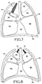
- FIG. 8 illustrates the respiratory system after both the lung portion 66 of the upper right lobe 56 and the lung portion 62 of the upper left lobe 52 have been treated as described above.
- the volumes of the right upper lung lobe 56 and left upper lung lobe 52 have been reduced in size by the jacket 72 .
- This causes the lung lobes to occupy less volume within the thorax 22 to permit the diaphragm 26 to assume its arched state for acting upon the remaining healthier lung tissue.
- this should result in improved pulmonary function due to enhanced elastic recoil, correction of ventilation/perfusion mismatch, improved efficiency of respiratory musculature, and improved right ventricle filling.
- FIG. 9 illustrates the respiratory system 20 just after suffering an air leak or rupture.
- the rupture 162 has occurred in lung lobe 58 .
- air is escaping from the lung lobe 58 as indicated by the arrow 164 .
- This individual is incapable of breathing normally.
- the negative pressure created by the moving diaphragm 26 causes some of the air taken into lobe 58 to be lost through the rupture 162 .
- the positive pressure produced thereby forces still more air from lobe 58 through the rupture.
- the lobe 58 collapses as illustrated in FIG. 10 and becomes nonfunctional to support respiration.
- FIG. 11 shows a lung constriction device 170 embodying the present invention in the process of being deployed on the effected lung lobe 58 .
- the device 170 is configured as a jacket formed of a sheet or flexible fabric of biocompatible material.
- the material may be both flexible and expandable material formed from silicone rubber, polyurethane, expanded polytetraflouroethylene, polyester and polyurethane, or nylon and polyurethane, for example. It may alternatively be flexible but nonexpandable formed from nylon, polytetraflouroethylene, or polyester, for example.
- the jacket is expandable, it may more specifically be formed from a sheet or fabric of 70% nylon and 30% polyurethane.
- the jacket is preferably opened at both ends 172 and 174 and, as illustrated, may be generally cylindrical in configuration.
- the jacket is applied to the portion of the lung lobe having the leak or puncture while the jacket is in an expanded condition. This may be accomplished, as will be seen hereinafter, by expanding the jacket and then pulling the lung portion into the jacket.
- the expansion of the device is released as seen, for example, in FIG. 12 .
- the jacket is permitted to contract or collapse about the lung portion to constrict the lung portion and effectively suppress the leak or puncture.
- the lung tissue may be collapsed as it is pulled into the jacket. Once disposed in the jacket, the lung tissue will remain constricted by the jacket.
- the use of the device 170 need not be restricted to the suppression of air leakages in lungs. It may, for example, find use to advantage in constricting a lung portion suffering from COPD to simulate or achieve lung volume reduction. All of the beneficial effects of lung volume reduction surgery may be realized and, most importantly, without requiring suturing of lung tissue.
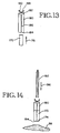
- FIGS. 13 - 18 illustrate a mechanical process for deploying the lung constriction device 170 .
- the device 170 is first aligned with an expansion mandrel or form 180 .
- the device 170 is then moved towards the form 180 as indicated by the arrow 176 .
- the form 180 is hollow, has opened ends 182 and 184 and has a configuration similar to that of the device 170 .
- the form has a longitudinal slit 186 rendering the form expandable in a transverse direction.
- the form further includes tabs 188 and 190 which, when pressed towards each other, cause the form to expand in the transverse direction.
- the device 170 is applied to the form 180 until the end 174 of the device 170 is at the end 184 of the form 180 as illustrated in FIG. 14 .
- An atraumatic instrument such as a forceps 142 , is then aligned with the form 180 and moved relative thereto through the form in the direction of arrow 196 and into engagement with the lung tissue 58 as illustrated in FIG. 15 .
- the forceps 192 are then used to grab the lung tissue 58 .
- the tabs 188 and 190 of the form 180 are pressed toward each other to cause the form 180 to expand in a transverse direction. This may be noticed by the longitudinal slit 186 becoming noticeably wider.
- the expansion of the form 180 in the transverse direction imparts an expansion force on the device 170 , causing it to similarly expand to an expanded condition.
- the forceps are then retracted as illustrated in FIG. 16 in the direction of arrow 198 , to pull the lung tissue into the form 180 and device 170 .
- the lung tissue is pulled until it extends entirely through the device 170 .
- the process continues as illustrated in FIG. 17 .
- the tabs 188 and 190 are released.
- the device 170 remains in an expanded condition.
- a suitable instrument 194 is used to hold the device 170 in place while the form 180 is moved in the direction of the arrow 200 to withdraw the form 180 from the device 170 .
- the process is completed when the form 180 is totally withdrawn from the device 170 .
- the expansion force applied to the device 170 by the form 180 is released, permitting the device 170 to collapse or contract about the lung tissue 58 drawn into the device 170 .
- the device 170 now constricts the lung tissue to effect air leak suppression or lung volume reduction, for example.
- the form 180 need not be expandable if the device 170 is not expandable.
- the process of pulling the lung tissue into the mandrel 180 and device 170 will cause the lung tissue to collapse.
- the device 170 being dimensioned for constricting the lung tissue, once the mandrel is removed, the lung tissue will remain in and be constricted by the device 170 as illustrated in FIG. 18 .
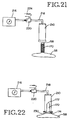
- FIGS. 19 - 21 illustrate another embodiment of deploying the lung constriction device 170 in accordance with further aspects of the present invention.
- vacuum pressure is utilized instead for pulling the lung tissue into the device 170 . This permits the procedure to be more automated and potentially less traumatic to the lung tissue being constricted.
- the mandrel or form 210 takes the form of a cylinder having an opened end 212 and a closed end 214 .
- the closed end 214 is coupled to a vacuum source 216 through a conduit 218 and a valve 220 .
- the valve 220 has an aperture 222 which, when closed by, for example, a finger 224 , causes the vacuum to be pulled through the conduit 218 and form 210 .
- the valve is in an opened condition.
- the form 210 has a diameter dimension 226 which is substantially greater than the diameter dimension of the device 170 when the device is expandable and in a nonexpanded condition. As seen in FIG. 19 , the device 170 has been applied over the form 210 so that the form imparts an expansion force to the device 170 . The opened end 212 of the form 210 is in contact with the lung tissue 58 to be constricted.
- the finger 224 has now closed the valve 220 .
- the vacuum is now being pulled through the conduit 218 and form 210 . This causes the lung tissue 58 to be pulled into the form 210 and the device 170 while the device 170 is in an expanded condition.
- the device may be held in position and the form 210 withdrawn from the device 170 and the lung tissue 58 .
- the vacuum suction may be released by opening the valve 220 .
- the expansion force of the form 210 on the device 170 is released to permit the device 170 to collapse or contract about the lung tissue 58 .
- the device 170 is now deployed for constricting the lung tissue and providing leak suppression or lung volume reduction, for example.
- the device 170 need not be expandable.
- the form 210 may have the same or approximately the same dimensions as the device 170 .
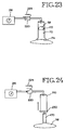
- FIGS. 22 - 24 illustrate a further embodiment of deploying the lung constriction device 170 .
- a vacuum suction is utilized for pulling the lung tissue into the device 170 .
- the vacuum source 216 , the conduit 218 , and the valve 220 are again used to establish the vacuum suction in the form 210 .
- the device 170 is positioned inside of the form 210 with the end 174 of the device 170 being stretched and held by the lip 230 of the form 210 .
- the valve 220 is closed, the vacuum is pulled through the mandrel 210 and the device 170 due to the opened end 172 of the device 170 .
- the lung tissue 58 when the lung tissue 58 is brought into engagement with the end 174 of the device 170 and the vacuum is pulled with the closure of valve 220 , the lung tissue is pulled directly into the device 170 as illustrated in FIG. 23.
- the vacuum is pulled until the lung tissue 58 to be constricted preferably extends entirely through the device 170 past the end 172 .
- the lung tissue itself exerts an expansion force on the device 170 as the lung tissue is pulled into the device 170 .
- the end 174 of the device 170 may be released from the lip 230 of the form 210 to permit the form 210 to be withdrawn from the device 170 .
- the vacuum suction may be released by opening the valve 220 .
- the release of the vacuum also releases the expansion force on the device 170 .
- the device is permitted to collapse or contract about the lung tissue 58.
- the device 170 is now deployed for constricting the lung tissue and providing leak suppression or lung volume reduction, for example.
- the form or mandrel 210 may be of the same dimension or slightly larger dimension than the device 170 to permit an effective seal between the lip 230 of mandrel or form 210 and the end 174 of the device 170 .
- the vacuum suction will still be pulled through the form 210 and the device 170 .
- the lung tissue collapses.
- the collapsed lung tissue will remain constricted in the device 170 to provide, for example, lung leakage suppression or lung volume reduction.
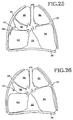
- FIG. 25 it illustrates a manner in which the lung constriction apparatus 170 may be employed for effecting lung volume reduction to a greater extent.
- the lung portion 59 of lobe 58 has been pulled through the device 170 and is being constricted by the device 170 .
- the device 170 and the manner of pulling the lung portion 59 therethrough may conform to any of the embodiments previously described herein.
- the device 170 is formed of severable material, such as, any of the materials previously described. This enables the device or jacket 170 to be severed or cut intermediate its ends as illustrated in FIG. 26 to section the lung portion 59. The portion of the device 170 remaining on the lobe 58 continues to constrict the lung tissue therein to form an effective seal from leakage. Hence, in accordance with this embodiment of the present invention, lung volume reduction is rendered an available treatment while negating the need of conventional lung sectioning and suturing thus avoiding the potentially severe complications which accompany those procedures.
- a lung constriction device ( 70, 170 ) and method provide lung air leak suppression or lung volume reduction.
- the lung constriction device includes a jacket of flexible material.
- the jacket is configured to cover at least a portion of a lung.
- the jacket is further configured to receive the lung portion as it is drawn therein.
- the jacket may be expandable and held in an expanded condition as the lung tissue is drawn into the jacket. Thereafter, the jacket is permitted to collapse about the lung portion to constrict the lung portion.
- the jacket may alternatively be nonexpandable. As the lung tissue is drawn into the jacket, it will collapse. Once disposed in the jacket, the jacket constricts the lung tissue to provide leakage suppression or lung volume reduction.
- the jacket may further be severable so that after the lung portion is drawn into the jacket, the jacket may be severed to section the lung portion.
Abstract
Description
Claims (46)
- A lung constricting device characterized by a jacket (70, 170) of flexible material configured to cover at least a portion of a lung and to constrict the lung portion.
- The device of claim 1 further characterized by the flexible material being a flexible fabric.
- The device of claim 1 further characterized by the jacket (70, 170) including an opening (74, 174) for applying the jacket to the lung portion.
- The device of claim 3 further characterized by the jacket (70) including a base defining the opening.
- The device of claim 4 further characterized by collapsing means (82) carried by the jacket to collapse the jacket about the lung portion.
- The device of claim 5 further characterized by a guide tube (88) for guiding the collapsing means.
- The device of claim 4 further characterized by the collapsing means circumscribing the jacket at the base.
- The device of claim 1 further characterized by the flexible material being formed of polyester.
- The device of claim 1 further characterized by the jacket (170) having a pair of opened ends (172, 174) to permit the lung portion to be drawn into the jacket.
- The device of claim 1 further characterized by the jacket being formed of elastic material for collapsing about the lung portion.
- The device of claim 1 further characterized by the jacket being formed of a mesh material.
- The device of claim 1 further characterized by the jacket being formed of one of silicone rubber, polyester, polyurethane, nylon, polytetraflouroethylene, expanded polytetraflouroethylene, polyester and polyurethane, and nylon and polyurethane.
- The device of claim 1 further characterized by the jacket being formed of an expandable mesh material.
- The device of claim 1 further characterized by the jacket being formed of a severable material to permit the device to be severed intermediate its ends.
- The device of claim 1 further characterized by being formed of expandable material, configured for receiving a lung portion when forced into an expanded enlarged condition by an expansion force, and contractible about the lung portion upon release of the expansion force for constricting the lung portion.
- The device of claim 15 further characterized by being a hollow, substantially cylindrical configuration when in a nonexpanded condition.
- The device of claim 16 further characterized by a first opened end (74, 174) for receiving the lung portion.
- The device of claim 17 further characterized by a second opened end (172) for permitting the lung portion to extend through the jacket (170).
- The device of claim 15 further characterized by being formed of one of silicone rubber, polyurethane, expanded polytetraflouroethylene, nylon and polyurethane, and polyester and polyurethane.
- The device of claim 15 further characterized by being formed of an expandable mesh material.
- The device of claim 15 further characterized by being formed of a severable material.
- A method of constricting a portion of a lung, the method characterized by: providing a jacket (70, 170) formed of flexible material; and disposing the jacket about the lung portion.
- The method of claim 22 further characterized by the jacket being formed of an open mesh material.
- The method of claim 23 further characterized by the open mesh material being a polyester mesh.
- The method of claim 22 further characterized by the step of providing the jacket with a closed end and an opening to permit disposing the jacket over the lung portion.
- The method of claim 25 further characterized by collapsing the jacket about the lung portion.
- The method of claim 26 further characterized by the collapsing step including circumscribing the opening with a cord (96), the cord having a pair of free ends (98, 100) and pulling on the free ends of the cord to collapse the opening of the jacket about the lung portion.
- The method of claim 27 further characterized by the collapsing step further including tying the free ends of the cord together.
- The method of claim 22 further characterized by deflating the lung portion prior to disposing the jacket over the lung portion.
- The method of claim 22 further characterized by the disposing step including drawing the lung portion into the jacket.
- The method of claim 30 further characterized by the jacket being dimensioned to constrict the lung portion and wherein the drawing step includes collapsing the lung portion while drawing the lung portion into the jacket.
- The method of claim 31 further characterized by the drawing step including physically pulling the lung portion into the jacket.
- The method of claim 30 further characterized by the step of positioning the jacket (170) on a mandrel (180, 210), physically pulling the lung portion pulled into the mandrel, and removing the mandrel from the jacket and the lung portion to leave the lung portion constricted in the jacket.
- The method of claim 31 further characterized by the drawing step including applying a vacuum suction to the lung portion.
- The method of claim 34 further characterized by the step of positioning the jacket (170) on a mandrel (210), the vacuum suction being applied to the lung portion through the mandrel, and removing the mandrel from the jacket and the lung portion to leave the lung portion constricted in the jacket.
- The method of claim 34 further characterized by positioning the jacket (170) within a mandrel (210), the vacuum suction being applied to the lung portion through the mandrel and the jacket to pull the lung portion directly into the jacket, and removing the mandrel from the jacket.
- The method of claim 30 further characterized by the jacket being formed of expandable material and applying an expansion force to the jacket to enlarge the jacket dimensions and releasing the expansion force on the jacket after the drawing step to permit the jacket to collapse the jacket about the lung portion for constricting the lung portion.
- The method of claim 37 further characterized by the applying step including positioning the jacket on a mandrel.
- The method of claim 38 further characterized by the applying step further including expanding the mandrel after positioning the jacket on the mandrel.
- The method of claim 37 further characterized by the drawing step including physically pulling the lung portion.
- The method of claim 37 further characterized by the drawing step including applying a vacuum suction to the lung portion.
- The method of claim 38 further characterized by the drawing step including applying a vacuum suction to the lung portion through the mandrel to draw the lung portion into the mandrel and the releasing step including removing the jacket from the mandrel.
- The method of claim 42 further characterized by the releasing step including terminating the vacuum suction prior to removing the jacket from the mandrel.
- The method of claim 37 further characterized by positioning the jacket within a mandrel, and applying a vacuum suction to the lung portion through the mandrel and the jacket to cause the lung portion to be drawn into the jacket and the jacket to be expanded by the lung portion drawn by the vacuum suction.
- The method of claim 44 further characterized by the releasing step including terminating the vacuum suction.
- The method of claim 22 further characterized severing the jacket after disposing the lung portion into the jacket to section the lung portion.
Applications Claiming Priority (4)
| Application Number | Priority Date | Filing Date | Title |
|---|---|---|---|
| US534244 | 1990-06-07 | ||
| US09/379,973 US6416554B1 (en) | 1999-08-24 | 1999-08-24 | Lung reduction apparatus and method |
| US379973 | 1999-08-24 | ||
| US09/534,244 US6328689B1 (en) | 2000-03-23 | 2000-03-23 | Lung constriction apparatus and method |
Publications (3)
| Publication Number | Publication Date |
|---|---|
| EP1078601A2 true EP1078601A2 (en) | 2001-02-28 |
| EP1078601A3 EP1078601A3 (en) | 2002-05-22 |
| EP1078601B1 EP1078601B1 (en) | 2006-10-04 |
Family
ID=27008845
Family Applications (1)
| Application Number | Title | Priority Date | Filing Date |
|---|---|---|---|
| EP00118072A Expired - Lifetime EP1078601B1 (en) | 1999-08-24 | 2000-08-23 | Kit for lung volume reduction |
Country Status (5)
| Country | Link |
|---|---|
| EP (1) | EP1078601B1 (en) |
| JP (1) | JP3728192B2 (en) |
| AT (1) | ATE341278T1 (en) |
| DE (1) | DE60031052T2 (en) |
| ES (1) | ES2272225T3 (en) |
Cited By (28)
| Publication number | Priority date | Publication date | Assignee | Title |
|---|---|---|---|---|
| WO2002078552A1 (en) * | 2001-03-28 | 2002-10-10 | George Kaladelfos | Treatment of vault prolapse |
| US6514290B1 (en) | 2000-03-31 | 2003-02-04 | Broncus Technologies, Inc. | Lung elastic recoil restoring or tissue compressing device and method |
| US6527761B1 (en) | 2000-10-27 | 2003-03-04 | Pulmonx, Inc. | Methods and devices for obstructing and aspirating lung tissue segments |
| WO2003028560A1 (en) * | 2001-10-02 | 2003-04-10 | Spiration, Inc. | Constriction device including reinforced suture holes |
| US6632243B1 (en) | 1997-09-16 | 2003-10-14 | Emphasys Medical Inc. | Body fluid flow control device |
| US6679264B1 (en) | 2000-03-04 | 2004-01-20 | Emphasys Medical, Inc. | Methods and devices for use in performing pulmonary procedures |
| EP1411840A2 (en) * | 2001-07-10 | 2004-04-28 | Spiration, Inc. | Constriction device including fixation structure |
| US7753933B2 (en) | 2000-12-14 | 2010-07-13 | Ensure Medical, Inc. | Plug with detachable guidewire element and methods for use |
| US7814912B2 (en) | 2002-11-27 | 2010-10-19 | Pulmonx Corporation | Delivery methods and devices for implantable bronchial isolation devices |
| US7883471B2 (en) | 2001-09-10 | 2011-02-08 | Pulmonx Corporation | Minimally invasive determination of collateral ventilation in lungs |
| US8057510B2 (en) | 2000-12-14 | 2011-11-15 | Ensure Medical, Inc. | Plug with collet and apparatus and method for delivering such plugs |
| US8075587B2 (en) | 2000-12-14 | 2011-12-13 | Ensure Medical, Inc. | Apparatus and methods for sealing vascular punctures |
| US8088144B2 (en) | 2005-05-04 | 2012-01-03 | Ensure Medical, Inc. | Locator and closure device and method of use |
| US8251067B2 (en) | 2001-03-02 | 2012-08-28 | Pulmonx Corporation | Bronchial flow control devices with membrane seal |
| US8388682B2 (en) | 2004-11-19 | 2013-03-05 | Pulmonx Corporation | Bronchial flow control devices and methods of use |
| US8474460B2 (en) | 2000-03-04 | 2013-07-02 | Pulmonx Corporation | Implanted bronchial isolation devices and methods |
| US8579934B2 (en) | 2003-10-17 | 2013-11-12 | Ensure Medical, Inc. | Locator and delivery device and method of use |
| US8603127B2 (en) | 2002-03-20 | 2013-12-10 | Spiration, Inc. | Removable anchored lung volume reduction devices and methods |
| US8852229B2 (en) | 2003-10-17 | 2014-10-07 | Cordis Corporation | Locator and closure device and method of use |
| US8876791B2 (en) | 2005-02-25 | 2014-11-04 | Pulmonx Corporation | Collateral pathway treatment using agent entrained by aspiration flow current |
| US8926654B2 (en) | 2005-05-04 | 2015-01-06 | Cordis Corporation | Locator and closure device and method of use |
| US9211181B2 (en) | 2004-11-19 | 2015-12-15 | Pulmonx Corporation | Implant loading device and system |
| US9492148B2 (en) | 2000-12-14 | 2016-11-15 | CARDINAL HEALTH SWITZERLAND 515 GmbH | Apparatus and methods for sealing vascular punctures |
| US9622752B2 (en) | 2003-08-08 | 2017-04-18 | Spiration, Inc. | Bronchoscopic repair of air leaks in a lung |
| US9655602B2 (en) | 2000-12-14 | 2017-05-23 | CARDINAL HEALTH SWITZERLAND 515 GmbH | Vascular plug having composite construction |
| US10413244B2 (en) | 2001-09-10 | 2019-09-17 | Pulmonx Corporation | Method and apparatus for endobronchial diagnosis |
| WO2022217292A3 (en) * | 2021-04-08 | 2022-12-15 | The Foundry, Llc | Devices, systems, and methods for treating pulmonary disease |
| US11883029B2 (en) | 2005-01-20 | 2024-01-30 | Pulmonx Corporation | Methods and devices for passive residual lung volume reduction and functional lung volume expansion |
Families Citing this family (10)
| Publication number | Priority date | Publication date | Assignee | Title |
|---|---|---|---|---|
| US20030050648A1 (en) | 2001-09-11 | 2003-03-13 | Spiration, Inc. | Removable lung reduction devices, systems, and methods |
| WO2003030975A2 (en) | 2001-10-11 | 2003-04-17 | Emphasys Medical, Inc. | Bronchial flow control devices and methods of use |
| US6592594B2 (en) | 2001-10-25 | 2003-07-15 | Spiration, Inc. | Bronchial obstruction device deployment system and method |
| US20030216769A1 (en) | 2002-05-17 | 2003-11-20 | Dillard David H. | Removable anchored lung volume reduction devices and methods |
| US8206684B2 (en) | 2004-02-27 | 2012-06-26 | Pulmonx Corporation | Methods and devices for blocking flow through collateral pathways in the lung |
| US20080228137A1 (en) | 2007-03-12 | 2008-09-18 | Pulmonx | Methods and devices for passive residual lung volume reduction and functional lung volume expansion |
| US8496006B2 (en) | 2005-01-20 | 2013-07-30 | Pulmonx Corporation | Methods and devices for passive residual lung volume reduction and functional lung volume expansion |
| US8523782B2 (en) | 2005-12-07 | 2013-09-03 | Pulmonx Corporation | Minimally invasive determination of collateral ventilation in lungs |
| US7691151B2 (en) | 2006-03-31 | 2010-04-06 | Spiration, Inc. | Articulable Anchor |
| US8795241B2 (en) | 2011-05-13 | 2014-08-05 | Spiration, Inc. | Deployment catheter |
Family Cites Families (3)
| Publication number | Priority date | Publication date | Assignee | Title |
|---|---|---|---|---|
| US5398844A (en) * | 1994-01-31 | 1995-03-21 | Boston Scientific Corporation | Multiple ligating band dispenser |
| IT1284108B1 (en) * | 1996-07-04 | 1998-05-08 | Carlo Rebuffat | SURGICAL PRESIDIUM FOR THE TREATMENT OF PULMONARY EMPHYSEMA |
| US5702343A (en) * | 1996-10-02 | 1997-12-30 | Acorn Medical, Inc. | Cardiac reinforcement device |
-
2000
- 2000-08-23 ES ES00118072T patent/ES2272225T3/en not_active Expired - Lifetime
- 2000-08-23 EP EP00118072A patent/EP1078601B1/en not_active Expired - Lifetime
- 2000-08-23 DE DE60031052T patent/DE60031052T2/en not_active Expired - Lifetime
- 2000-08-23 AT AT00118072T patent/ATE341278T1/en not_active IP Right Cessation
- 2000-08-24 JP JP2000253750A patent/JP3728192B2/en not_active Expired - Fee Related
Non-Patent Citations (1)
| Title |
|---|
| None |
Cited By (40)
| Publication number | Priority date | Publication date | Assignee | Title |
|---|---|---|---|---|
| US6632243B1 (en) | 1997-09-16 | 2003-10-14 | Emphasys Medical Inc. | Body fluid flow control device |
| US6679264B1 (en) | 2000-03-04 | 2004-01-20 | Emphasys Medical, Inc. | Methods and devices for use in performing pulmonary procedures |
| US8474460B2 (en) | 2000-03-04 | 2013-07-02 | Pulmonx Corporation | Implanted bronchial isolation devices and methods |
| US6694979B2 (en) | 2000-03-04 | 2004-02-24 | Emphasys Medical, Inc. | Methods and devices for use in performing pulmonary procedures |
| US6514290B1 (en) | 2000-03-31 | 2003-02-04 | Broncus Technologies, Inc. | Lung elastic recoil restoring or tissue compressing device and method |
| US6997918B2 (en) | 2000-10-27 | 2006-02-14 | Pulmonx | Methods and devices for obstructing and aspirating lung tissue segments |
| US6527761B1 (en) | 2000-10-27 | 2003-03-04 | Pulmonx, Inc. | Methods and devices for obstructing and aspirating lung tissue segments |
| US9492148B2 (en) | 2000-12-14 | 2016-11-15 | CARDINAL HEALTH SWITZERLAND 515 GmbH | Apparatus and methods for sealing vascular punctures |
| US9655602B2 (en) | 2000-12-14 | 2017-05-23 | CARDINAL HEALTH SWITZERLAND 515 GmbH | Vascular plug having composite construction |
| US8888812B2 (en) | 2000-12-14 | 2014-11-18 | Cordis Corporation | Plug with collet and apparatus and methods for delivering such plugs |
| US8057510B2 (en) | 2000-12-14 | 2011-11-15 | Ensure Medical, Inc. | Plug with collet and apparatus and method for delivering such plugs |
| US8409248B2 (en) | 2000-12-14 | 2013-04-02 | Core Medical, Inc. | Plug with detachable guidewire element and methods for use |
| US7753933B2 (en) | 2000-12-14 | 2010-07-13 | Ensure Medical, Inc. | Plug with detachable guidewire element and methods for use |
| US8075587B2 (en) | 2000-12-14 | 2011-12-13 | Ensure Medical, Inc. | Apparatus and methods for sealing vascular punctures |
| US8251067B2 (en) | 2001-03-02 | 2012-08-28 | Pulmonx Corporation | Bronchial flow control devices with membrane seal |
| US7175591B2 (en) | 2001-03-28 | 2007-02-13 | George Kaladelfos | Treatment of vault prolapse |
| WO2002078552A1 (en) * | 2001-03-28 | 2002-10-10 | George Kaladelfos | Treatment of vault prolapse |
| EP1411840A4 (en) * | 2001-07-10 | 2008-07-09 | Spiration Inc | Constriction device including fixation structure |
| EP1411840A2 (en) * | 2001-07-10 | 2004-04-28 | Spiration, Inc. | Constriction device including fixation structure |
| US7883471B2 (en) | 2001-09-10 | 2011-02-08 | Pulmonx Corporation | Minimally invasive determination of collateral ventilation in lungs |
| US8454527B2 (en) | 2001-09-10 | 2013-06-04 | Pulmonx Corporation | Minimally invasive determination of collateral ventilation in lungs |
| US10413244B2 (en) | 2001-09-10 | 2019-09-17 | Pulmonx Corporation | Method and apparatus for endobronchial diagnosis |
| US6632239B2 (en) | 2001-10-02 | 2003-10-14 | Spiration, Inc. | Constriction device including reinforced suture holes |
| WO2003028560A1 (en) * | 2001-10-02 | 2003-04-10 | Spiration, Inc. | Constriction device including reinforced suture holes |
| US8603127B2 (en) | 2002-03-20 | 2013-12-10 | Spiration, Inc. | Removable anchored lung volume reduction devices and methods |
| US7814912B2 (en) | 2002-11-27 | 2010-10-19 | Pulmonx Corporation | Delivery methods and devices for implantable bronchial isolation devices |
| US9622752B2 (en) | 2003-08-08 | 2017-04-18 | Spiration, Inc. | Bronchoscopic repair of air leaks in a lung |
| US8579934B2 (en) | 2003-10-17 | 2013-11-12 | Ensure Medical, Inc. | Locator and delivery device and method of use |
| US8852229B2 (en) | 2003-10-17 | 2014-10-07 | Cordis Corporation | Locator and closure device and method of use |
| US9872755B2 (en) | 2004-11-19 | 2018-01-23 | Pulmonx Corporation | Implant loading device and system |
| US9211181B2 (en) | 2004-11-19 | 2015-12-15 | Pulmonx Corporation | Implant loading device and system |
| US8388682B2 (en) | 2004-11-19 | 2013-03-05 | Pulmonx Corporation | Bronchial flow control devices and methods of use |
| US11083556B2 (en) | 2004-11-19 | 2021-08-10 | Pulmonx Corporation | Implant loading device and system |
| US11883029B2 (en) | 2005-01-20 | 2024-01-30 | Pulmonx Corporation | Methods and devices for passive residual lung volume reduction and functional lung volume expansion |
| US8876791B2 (en) | 2005-02-25 | 2014-11-04 | Pulmonx Corporation | Collateral pathway treatment using agent entrained by aspiration flow current |
| US9289198B2 (en) | 2005-05-04 | 2016-03-22 | Cordis Corporation | Locator and closure device and method of use |
| US8926654B2 (en) | 2005-05-04 | 2015-01-06 | Cordis Corporation | Locator and closure device and method of use |
| US8088144B2 (en) | 2005-05-04 | 2012-01-03 | Ensure Medical, Inc. | Locator and closure device and method of use |
| US10350048B2 (en) | 2011-09-23 | 2019-07-16 | Pulmonx Corporation | Implant loading device and system |
| WO2022217292A3 (en) * | 2021-04-08 | 2022-12-15 | The Foundry, Llc | Devices, systems, and methods for treating pulmonary disease |
Also Published As
| Publication number | Publication date |
|---|---|
| EP1078601B1 (en) | 2006-10-04 |
| DE60031052T2 (en) | 2007-04-05 |
| JP2001087270A (en) | 2001-04-03 |
| JP3728192B2 (en) | 2005-12-21 |
| DE60031052D1 (en) | 2006-11-16 |
| ES2272225T3 (en) | 2007-05-01 |
| EP1078601A3 (en) | 2002-05-22 |
| ATE341278T1 (en) | 2006-10-15 |
Similar Documents
| Publication | Publication Date | Title |
|---|---|---|
| EP1078601B1 (en) | Kit for lung volume reduction | |
| US6328689B1 (en) | Lung constriction apparatus and method | |
| AU2002362449B2 (en) | Constriction device including reinforced suture holes | |
| US6416554B1 (en) | Lung reduction apparatus and method | |
| US7347814B2 (en) | Constriction device viewable under X ray fluoroscopy | |
| AU2002353813B2 (en) | Constriction device including tear resistant structures | |
| US6491706B1 (en) | Constriction device including fixation structure | |
| AU2002362449A1 (en) | Constriction device including reinforced suture holes | |
| AU2002353813A1 (en) | Constriction device including tear resistant structures | |
| AU2002354640A1 (en) | Construction device viewable under X ray fluoroscopy |
Legal Events
| Date | Code | Title | Description |
|---|---|---|---|
| PUAI | Public reference made under article 153(3) epc to a published international application that has entered the european phase |
Free format text: ORIGINAL CODE: 0009012 |
|
| AK | Designated contracting states |
Kind code of ref document: A2 Designated state(s): AT BE CH CY DE DK ES FI FR GB GR IE IT LI LU MC NL PT SE |
|
| AX | Request for extension of the european patent |
Free format text: AL;LT;LV;MK;RO;SI |
|
| PUAL | Search report despatched |
Free format text: ORIGINAL CODE: 0009013 |
|
| AX | Request for extension of the european patent |
Free format text: AL;LT;LV;MK;RO;SI |
|
| RIC1 | Information provided on ipc code assigned before grant |
Free format text: 7A 61B 17/12 A, 7A 61F 2/00 B |
|
| 17P | Request for examination filed |
Effective date: 20020827 |
|
| AKX | Designation fees paid |
Designated state(s): AT BE CH CY DE DK ES FI FR GB GR IE IT LI LU MC NL PT SE |
|
| 17Q | First examination report despatched |
Effective date: 20030312 |
|
| GRAP | Despatch of communication of intention to grant a patent |
Free format text: ORIGINAL CODE: EPIDOSNIGR1 |
|
| RTI1 | Title (correction) |
Free format text: KIT FOR LUNG VOLUME REDUCTION |
|
| GRAS | Grant fee paid |
Free format text: ORIGINAL CODE: EPIDOSNIGR3 |
|
| GRAA | (expected) grant |
Free format text: ORIGINAL CODE: 0009210 |
|
| AK | Designated contracting states |
Kind code of ref document: B1 Designated state(s): AT BE CH CY DE DK ES FI FR GB GR IE IT LI LU MC NL PT SE |
|
| PG25 | Lapsed in a contracting state [announced via postgrant information from national office to epo] |
Ref country code: IT Free format text: LAPSE BECAUSE OF FAILURE TO SUBMIT A TRANSLATION OF THE DESCRIPTION OR TO PAY THE FEE WITHIN THE PRESCRIBED TIME-LIMIT;WARNING: LAPSES OF ITALIAN PATENTS WITH EFFECTIVE DATE BEFORE 2007 MAY HAVE OCCURRED AT ANY TIME BEFORE 2007. THE CORRECT EFFECTIVE DATE MAY BE DIFFERENT FROM THE ONE RECORDED. Effective date: 20061004 Ref country code: BE Free format text: LAPSE BECAUSE OF FAILURE TO SUBMIT A TRANSLATION OF THE DESCRIPTION OR TO PAY THE FEE WITHIN THE PRESCRIBED TIME-LIMIT Effective date: 20061004 Ref country code: FI Free format text: LAPSE BECAUSE OF FAILURE TO SUBMIT A TRANSLATION OF THE DESCRIPTION OR TO PAY THE FEE WITHIN THE PRESCRIBED TIME-LIMIT Effective date: 20061004 Ref country code: NL Free format text: LAPSE BECAUSE OF FAILURE TO SUBMIT A TRANSLATION OF THE DESCRIPTION OR TO PAY THE FEE WITHIN THE PRESCRIBED TIME-LIMIT Effective date: 20061004 Ref country code: AT Free format text: LAPSE BECAUSE OF FAILURE TO SUBMIT A TRANSLATION OF THE DESCRIPTION OR TO PAY THE FEE WITHIN THE PRESCRIBED TIME-LIMIT Effective date: 20061004 Ref country code: CH Free format text: LAPSE BECAUSE OF FAILURE TO SUBMIT A TRANSLATION OF THE DESCRIPTION OR TO PAY THE FEE WITHIN THE PRESCRIBED TIME-LIMIT Effective date: 20061004 Ref country code: LI Free format text: LAPSE BECAUSE OF FAILURE TO SUBMIT A TRANSLATION OF THE DESCRIPTION OR TO PAY THE FEE WITHIN THE PRESCRIBED TIME-LIMIT Effective date: 20061004 |
|
| REG | Reference to a national code |
Ref country code: GB Ref legal event code: FG4D |
|
| REG | Reference to a national code |
Ref country code: CH Ref legal event code: EP |
|
| REG | Reference to a national code |
Ref country code: IE Ref legal event code: FG4D |
|
| REF | Corresponds to: |
Ref document number: 60031052 Country of ref document: DE Date of ref document: 20061116 Kind code of ref document: P |
|
| PG25 | Lapsed in a contracting state [announced via postgrant information from national office to epo] |
Ref country code: SE Free format text: LAPSE BECAUSE OF FAILURE TO SUBMIT A TRANSLATION OF THE DESCRIPTION OR TO PAY THE FEE WITHIN THE PRESCRIBED TIME-LIMIT Effective date: 20070104 Ref country code: DK Free format text: LAPSE BECAUSE OF FAILURE TO SUBMIT A TRANSLATION OF THE DESCRIPTION OR TO PAY THE FEE WITHIN THE PRESCRIBED TIME-LIMIT Effective date: 20070104 |
|
| PG25 | Lapsed in a contracting state [announced via postgrant information from national office to epo] |
Ref country code: PT Free format text: LAPSE BECAUSE OF FAILURE TO SUBMIT A TRANSLATION OF THE DESCRIPTION OR TO PAY THE FEE WITHIN THE PRESCRIBED TIME-LIMIT Effective date: 20070316 |
|
| NLV1 | Nl: lapsed or annulled due to failure to fulfill the requirements of art. 29p and 29m of the patents act | ||
| ET | Fr: translation filed | ||
| REG | Reference to a national code |
Ref country code: CH Ref legal event code: PL |
|
| REG | Reference to a national code |
Ref country code: ES Ref legal event code: FG2A Ref document number: 2272225 Country of ref document: ES Kind code of ref document: T3 |
|
| PLBE | No opposition filed within time limit |
Free format text: ORIGINAL CODE: 0009261 |
|
| STAA | Information on the status of an ep patent application or granted ep patent |
Free format text: STATUS: NO OPPOSITION FILED WITHIN TIME LIMIT |
|
| 26N | No opposition filed |
Effective date: 20070705 |
|
| PG25 | Lapsed in a contracting state [announced via postgrant information from national office to epo] |
Ref country code: MC Free format text: LAPSE BECAUSE OF NON-PAYMENT OF DUE FEES Effective date: 20070831 Ref country code: GR Free format text: LAPSE BECAUSE OF FAILURE TO SUBMIT A TRANSLATION OF THE DESCRIPTION OR TO PAY THE FEE WITHIN THE PRESCRIBED TIME-LIMIT Effective date: 20070105 |
|
| PG25 | Lapsed in a contracting state [announced via postgrant information from national office to epo] |
Ref country code: IE Free format text: LAPSE BECAUSE OF NON-PAYMENT OF DUE FEES Effective date: 20070823 |
|
| PG25 | Lapsed in a contracting state [announced via postgrant information from national office to epo] |
Ref country code: CY Free format text: LAPSE BECAUSE OF FAILURE TO SUBMIT A TRANSLATION OF THE DESCRIPTION OR TO PAY THE FEE WITHIN THE PRESCRIBED TIME-LIMIT Effective date: 20061004 Ref country code: LU Free format text: LAPSE BECAUSE OF NON-PAYMENT OF DUE FEES Effective date: 20070823 |
|
| PGFP | Annual fee paid to national office [announced via postgrant information from national office to epo] |
Ref country code: IT Payment date: 20120810 Year of fee payment: 13 Ref country code: FR Payment date: 20120823 Year of fee payment: 13 Ref country code: ES Payment date: 20120907 Year of fee payment: 13 |
|
| REG | Reference to a national code |
Ref country code: FR Ref legal event code: ST Effective date: 20140430 |
|
| PG25 | Lapsed in a contracting state [announced via postgrant information from national office to epo] |
Ref country code: IT Free format text: LAPSE BECAUSE OF NON-PAYMENT OF DUE FEES Effective date: 20130823 |
|
| PG25 | Lapsed in a contracting state [announced via postgrant information from national office to epo] |
Ref country code: FR Free format text: LAPSE BECAUSE OF NON-PAYMENT OF DUE FEES Effective date: 20130902 |
|
| REG | Reference to a national code |
Ref country code: ES Ref legal event code: FD2A Effective date: 20141107 |
|
| PG25 | Lapsed in a contracting state [announced via postgrant information from national office to epo] |
Ref country code: ES Free format text: LAPSE BECAUSE OF NON-PAYMENT OF DUE FEES Effective date: 20130824 |
|
| PGFP | Annual fee paid to national office [announced via postgrant information from national office to epo] |
Ref country code: GB Payment date: 20150819 Year of fee payment: 16 Ref country code: DE Payment date: 20150818 Year of fee payment: 16 |
|
| REG | Reference to a national code |
Ref country code: DE Ref legal event code: R119 Ref document number: 60031052 Country of ref document: DE |
|
| GBPC | Gb: european patent ceased through non-payment of renewal fee |
Effective date: 20160823 |
|
| PG25 | Lapsed in a contracting state [announced via postgrant information from national office to epo] |
Ref country code: GB Free format text: LAPSE BECAUSE OF NON-PAYMENT OF DUE FEES Effective date: 20160823 Ref country code: DE Free format text: LAPSE BECAUSE OF NON-PAYMENT OF DUE FEES Effective date: 20170301 |