EP1078769A2 - Print element and method for assembling a print head - Google Patents
Print element and method for assembling a print head Download PDFInfo
- Publication number
- EP1078769A2 EP1078769A2 EP00307028A EP00307028A EP1078769A2 EP 1078769 A2 EP1078769 A2 EP 1078769A2 EP 00307028 A EP00307028 A EP 00307028A EP 00307028 A EP00307028 A EP 00307028A EP 1078769 A2 EP1078769 A2 EP 1078769A2
- Authority
- EP
- European Patent Office
- Prior art keywords
- ink
- assembly
- print element
- ink jet
- Prior art date
- Legal status (The legal status is an assumption and is not a legal conclusion. Google has not performed a legal analysis and makes no representation as to the accuracy of the status listed.)
- Granted
Links
Images


Classifications
-
- B—PERFORMING OPERATIONS; TRANSPORTING
- B41—PRINTING; LINING MACHINES; TYPEWRITERS; STAMPS
- B41J—TYPEWRITERS; SELECTIVE PRINTING MECHANISMS, i.e. MECHANISMS PRINTING OTHERWISE THAN FROM A FORME; CORRECTION OF TYPOGRAPHICAL ERRORS
- B41J2/00—Typewriters or selective printing mechanisms characterised by the printing or marking process for which they are designed
- B41J2/005—Typewriters or selective printing mechanisms characterised by the printing or marking process for which they are designed characterised by bringing liquid or particles selectively into contact with a printing material
- B41J2/01—Ink jet
- B41J2/17—Ink jet characterised by ink handling
- B41J2/175—Ink supply systems ; Circuit parts therefor
- B41J2/17503—Ink cartridges
- B41J2/1752—Mounting within the printer
- B41J2/17523—Ink connection
-
- B—PERFORMING OPERATIONS; TRANSPORTING
- B41—PRINTING; LINING MACHINES; TYPEWRITERS; STAMPS
- B41J—TYPEWRITERS; SELECTIVE PRINTING MECHANISMS, i.e. MECHANISMS PRINTING OTHERWISE THAN FROM A FORME; CORRECTION OF TYPOGRAPHICAL ERRORS
- B41J2/00—Typewriters or selective printing mechanisms characterised by the printing or marking process for which they are designed
- B41J2/005—Typewriters or selective printing mechanisms characterised by the printing or marking process for which they are designed characterised by bringing liquid or particles selectively into contact with a printing material
- B41J2/01—Ink jet
- B41J2/135—Nozzles
- B41J2/14—Structure thereof only for on-demand ink jet heads
- B41J2002/14362—Assembling elements of heads
Definitions
- the present invention relates to a print element for a thermal ink jet printing apparatus and, more particularly, to a print element which can be used in different printing apparatus and with different types of ink supplies.
- U.S. Patents 5,297,336 and 5,519,425 disclose an ink manifold formed with an ink supply into a unitary ink supply cartridge for a thermal ink jet printer.
- U.S. Patent 4,695,854 discloses an external manifold for an ink jet array.
- a print element comprising:
- a print element comprising a heat sink, a printed wiring member, a thermal ink jet assembly, and a manifold assembly.
- the printed wiring member is mounted on the heat sink.
- the thermal ink jet assembly is mounted to the heat sink.
- the manifold assembly is connected to the heat sink and the thermal ink jet assembly.
- the manifold assembly comprises a first mount for removably connecting a first source of ink to the manifold assembly and a first outlet to the thermal ink jet assembly.
- a print head comprising a housing and a print element.
- the housing has a receiving area for removably receiving at least one ink tank.
- the print element is connected to the housing and has a heat sink, a thermal ink jet assembly, and a manifold assembly.
- the manifold assembly has at least one mount for removably connecting the ink tank to the manifold assembly.
- the housing has an aperture. The manifold assembly extends through the aperture.
- a print head assembly comprising a carriage and two print heads connected to the carriage.
- Each print head has a housing and a print element connected to the housing.
- Each print element has a heat sink and an ink manifold assembly mounted to the heat sink and an ink jet assembly.
- a portion of the ink manifold assemblies are located in their respective housing receiving areas and the heat sinks are located at exterior sides of the housings and located between the two housings.
- a method of manufacturing ink jet printing components comprising steps of assembling a print element and optionally connecting the print element to a print head housing.
- the method of assembling a print element comprises steps of connecting a thermal ink jet assembly to a heat sink; connecting a printed wiring member to the heat sink; and connecting an ink manifold assembly to the heat sink and the thermal ink jet assembly.
- the print head housing has a receiving area for removably receiving an ink tank.
- the print element can be assembled in a first type of printing device without the print head housing and, a combined assembly of the print element and the print head housing can be assembled in a second type of printing device.
- FIG. 1 there is shown a perspective view of a print head assembly 10 incorporating features of the present invention.
- the present invention will be described with reference to the embodiments shown in the drawings, it should be understood that the present invention can be embodied in many alternate forms of embodiments.
- any suitable size, shape or type of elements or materials could be used.
- the print head assembly 10 generally comprises a carriage 12 and two print heads 14, 16 mounted to the carriage 12.
- the carriage 12 is intended to be movably mounted on a frame of a printing device, such as a thermal ink jet printer, for reciprocating lateral sliding movement on the frame as is generally known in the art.
- the first print head 14 is intended to be a black ink print head and the second print head 16 is intended to be a color ink print head.
- the print head assembly configuration could be varied, such as a carriage with only a single black ink print head, a carriage with multiple black ink print heads, a carriage with multiple color print heads, or any other suitable configuration.
- the first print head 14 generally comprises a housing 18, a print element 20, and a seal member 22.
- the housing 18 is preferably a one-piece molded plastic member.
- the housing 18 comprises a receiving area 24, an integrally formed resilient latch 26, substantially open top and front ends, and an aperture 28 extending through the housing.
- the receiving area 24 is suitably sized and shaped to removably receive an ink supply cartridge or tank 30.
- the tank 30 can be inserted into and removed from the receiving area 24 through the substantially open top and front ends of the housing 18.
- the latch 26 is configured to resiliently snap-lock latch the tank 30 inside the receiving area 24.
- the latch 26 can deflect in a general cantilever fashion.
- a user can deflect the top end of the latch 26 rearward for removing or unlatching the tank 30 from the housing 18.
- any suitable type of latching or mounting mechanism could be used to fix the tank 30 with the housing 18.
- the aperture 28 extends through a comer of the housing 18; through portions of the bottom wall 32 and the right side wall 34.
- the aperture could extend merely through the bottom wall 32 or through any one or more of the side walls of the housing 18.
- the print element 20 generally comprises a heat sink 36, a printed wiring member 38, a thermal ink jet assembly 40, an ink manifold assembly 42, a fluid seal 44, and a facetape 46.
- the print elements have thermal ink jet assemblies.
- the heat sink 36 is preferably a flat one-piece member, such as aluminium.
- the printed wiring member 38 includes electrically conductive traces on a substrate with contact pads 48 at one end and contact areas 50 at an opposite end.
- the printed wiring member 38 is fixedly attached directly on the heat sink 36 with the contact pads 48 at a rear end edge and the contact areas 50 at a bottom end edge.
- the member 38 has a general right angle of L-shaped configuration.
- the rear end of the heat sink 36 and the contact pads 48 are sized and shaped to be connected to an electrical connector, similar to a card edge connector, such as disclosed in U.S. Patent No.4,934,961, which is hereby incorporated by reference, but as a single row of contacts on one side of the card edge receiving area.
- any suitable electrical connection could be made.
- the member 38 also has holes therethrough for mounting posts of the ink manifold assembly 42 to extend through.
- the posts can extend into holes in the heat sink 36 for mounting the ink manifold assembly 42 to the heat sink 36.
- the thermal ink jet assembly 40 is fixedly attached to the side of the heat sink 36 at its bottom end edge.
- the ink jet assembly 40 is also operably connected to the contact areas 50 of the printed wiring member 38.
- the fluid seal 44 covers a side of the ink manifold assembly 42 and has slots 52 for ink to flow from an outlet of the ink manifold assembly 42 to the ink jet assembly 40.
- the printed wiring member 38, ink jet assembly 40, and ink manifold assembly 42 are mounted to one side 36a of the heat sink 36.
- mirror image components of these members 38, 40, 42 could be mounted to the opposite side 36b of the heat sink 36.
- the contact pads 48 could be located at a first location (on side 36a) or optimally located at a second different location (on side 36b).
- two sets of the members 38, 40, 42 could be mounted to the one member 36; one set on each side 36a, 36b.
- the ink manifold assembly 42 generally comprises a base member 54, a cover 56, and two filters 58, 60.
- the base member 54 and cover 56 are preferably comprised of molded plastic.
- the base member 54 generally comprises a first section 62 and a second section 64.
- the first section 62 includes mounting post 66 (only one of which is shown), a recess 68 for receiving and supporting the ink jet assembly 40, and an outlet 70 through the first section 62.
- the second section 64 extends generally perpendicularly from the first section 62.
- the second section 64 has an ink well 72 which receives the first filter 58 and is in communication with the outlet 70.
- the cover 56 is mounted on the second section 64 with the first filter 58 being sandwiched therebetween.
- the cover 56 includes a mount 74 extending upward from its top side.
- the second filter 60 is mounted inside the mount 74.
- the second filter 60 is a coarser filter then the first filter 58.
- the mount 74 is sized and shaped to extend into a receiving hole 76 in the ink tank 30 (see Fig. 2).
- the mount 74 is also suitably sized and shaped to have a hose or conduit (not shown) from a different type of ink supply mounted thereon around the outer perimeter of the mount.
- the mount 74 extends generally parallel relative to the heat sink 36.
- the print element 20 is manufactured and then connected to the housing 18.
- the housing 18 has mounting posts (not shown) on the exterior of its right side that extend into holes of the heat sink 36 and mount the heat sink 36 on the exterior of the right side of the housing 18.
- the ink manifold assembly 42 extends through the aperture 28 into the receiving area 24.
- the seal member 22 is placed against the interior bottom wall 32 of the housing 18 with the mount 74 extending through the hole 78 (see Fig. 2).
- the seal member 22 is preferably comprised of an elastomeric material and includes a resilient upwardly facing ridge 8.
- the ridge 80 functions as a spring.
- the ridge 80 is resiliently compressed or deflected when the tank 30 is inserted into the receiving area 24 and helps to distribute some of the mounting load, from the tank 30 being placed into the receiving area 24, onto the housing 18 rather than all of the load being placed against the mount 74 and the print element 20.
- the spring feature of the ridge 80 also biases the ink tank 30 towards the latch 26 to stabily hold the tank 30 with the print head 14 with minimal forces being exerted against the print element 20 and the otherwise undesired resultant movement of the ink jet assembly 40, during ink tank loading.
- the second print head 16 generally comprises a housing 188, a print element 120, and a seal member 122.
- the housing 118 is preferably a one-piece molded plastic member.
- the housing 118 comprises a receiving area 124, three integrally formed resilient latches 126, substantially open top and front ends, and an aperture 128 extending through the housing.
- the receiving area 124 is suitably sized and shaped to removably receive three ink supply cartridges or tanks similar to the black ink tank 30, but smaller in width and having color inks. The tanks can be inserted into and removed from the receiving area 124 through the substantially open top and front ends of the housing 118.
- the latches 126 are configured to resiliently snap-lock latch the tanks inside the receiving area 124.
- the latches 126 can deflect in a general cantilever fashion. A user can manually deflect the top end of the latches 126 rearward for removing or unlatching the tanks from the housing 118.
- any suitable type of latching or mounting mechanism could be used to fix the tanks with the housing 118.
- the aperture 128 extends through a corner of the housing 118 and through portions of the bottom wall 132 and the left side wall 133. However, in alternate embodiments the aperture could extend merely through the bottom wall 132 or through any one or more of the side walls of the housing 118.
- the print element 120 generally comprises a heat sink 136, a printed wiring member 138, a thermal ink jet assembly 140, an ink manifold assembly 142, a fluid seal 144, and a facetape 146.
- the heat sink 136 is preferably a flat one-piece member, such as aluminium.
- the heat sink 136 is exactly the same as the heat sink 36, but could be different.
- the printed wiring member 138 includes electrically conductive traces on a substrate with contact pads at a rear end and contact areas at an opposite bottom end.
- the printed wiring member 138 is fixedly attached directly on the heat sink 136 with the contact pads at a rear end edge and the contact areas at a bottom end edge.
- the member 138 has a general right angle or L- shaped configuration.
- the rear end of the heat sink 136 and the contact pads of the member 138 are preferably designed to have a card edge type of electrical connector removably mounted thereon similar to the heat sink 36 and contact pads 48.
- a single electrical connector can be mounted on the rear end of both heat sinks 36, 136 and electrically connected to both sets of contact pads.
- the member 138 also has holes therethrough for mounting posts of the ink manifold assembly 142 to extend through. The posts can extend into holes in the head sink 136 for mounting the ink manifold assembly 142 to the heat sink 136.
- the thermal ink jet assembly 140 is fixedly attached to the side of the heat sink 136 at its bottom end edge.
- the ink jet assembly 140 is also operably connected to the contact areas of the printed wiring member 138.
- the fluid seal 144 covers a side of the ink manifold assembly 142 and has slots 152 for ink to flow from outlets of the ink manifold assembly 142 to the ink jet assembly 140.
- the ink manifold assembly 142 generally comprises a base member 154, a cover 156, and two types of filters 158, 160.
- the base member 154 and cover 156 are preferably comprised of molded plastic.
- the base member 154 generally comprises a first section 162 and a second section 164.
- the first section 162 includes mounting post 166, a recess 168 for receiving and supporting the ink jet assembly 140, and three outlets 170a, 170b, 170c through the first section 162.
- the second section 164 extends generally perpendicularly from the first section 162 with three ink wells 172a, 172b, 172c which receive the filters 160 and are in communication with the outlets 170.
- the cover 156 is mounted on the second section 164 with the filters 160 being sandwiched therebetween.
- the cover 156 includes three mounts 174a, 174b, 174c extending upward from its top side.
- the filters 158 are mounted inside the mounts 174.
- the filters 158 are coarser filters than the filters 160.
- the mounts 174 are sized and shaped to extend into a receiving hole in the ink tanks (similar to Fig. 2).
- the mounts 174 are also suitably sized and shaped to have a hose or conduit (not shown) from a different type of ink supply mounted thereon around the outer perimeter of the mounts.
- the mounts 174 extends generally parallel relative to the heat sink 136.
- the print element 120 is manufactured and then connected to the housing 118.
- the housing 118 has mounting posts 119 on the exterior of its left side 133 that extend into holes of the heat sink 136 and mount the heat sink 136 to the exterior of the left side of the housing 118.
- the ink manifold assembly 142 extends through the aperture 128 into the receiving area 124.
- the seal member 122 is placed against the interior bottom wall of the housing 118 with the mounts 174 extending through holes 178.
- the seal member 122 is preferably comprised of an elastomeric material and includes a resilient upwardly facing ridge 180. The ridge 180 functions as a spring.
- the ridge 180 is resiliently compressed or deflected when the tanks are inserted into the receiving area 124 and helps to distribute some of the mounting load, from the tanks being placed into the receiving area 124, onto the housing 118 rather than all of the load being placed against the mounts 174 and the print element 120.
- the spring feature of the ridge 180 also biases the ink tanks towards the latches 126 to stabily hold the tanks with the print head 16 with minimal forces being exerted against the print element 120 and the otherwise undesired resultant movement of the ink jet assembly 140, during ink tank loading.
- the housing 118 also has notches 129 in its right side 134.
- the distal end 165 of the manifold assembly 142 had projections 167. When the print element 120 is mounted to the housing 118, the projections 167 extend into the notches 129 to stabily mount the distal end 165 to the housing 118.
- the first print head 14 is positioned on the left side of the carriage 12 and the second print head 16 is positioned on the right side of the carriage 12.
- the two heat sinks 36, 136 are, thus, located next to each other between the two housings 18, 118 under the section 13 of the carriage 12.
- the heat sinks 36, 136 can be directly connected to each other or, alternatively, connected to a portion of the carriage 12 which is sandwiched directly between the two heat sinks 36, 136. This provides the advantage of precisely locating the two print elements 20, 120 relative to each other even though they are two separate members and have their own separate and spaced ink tank receiving housings 18, 118.
- connection of the two print elements 20, 120 to each other is staggered or stepped relative to the front of the carriage 12 to provide a precise offset D, such as the length of 110 ink jets, between the front ends of the ink jet assemblies 40, 140.
- the offset D need not be provided or any suitable offset distance could be provided.
- the print element could be designed to have four ink tanks connected to it (one black and three color) and/or only one housing which can hold four or more ink tanks. The black ink could be replaced by three ink tanks; red-green-blue or low density inks for photographic printing.
- two of the three color print elements 120 could be used in a single device.
- the print element 20 can be used in a first type of printing device 200 without connecting the print element 20 to the housing 18.
- the first type of printing device 200 could have an ink supply 202 which is spaced from the print element 20 and connected to the mount 74 by a supply conduit or tube 204.
- Fig. 8B illustrates that the same type of print element 20 can be mounted with the housing 18 at step 206 to form the print head 14 which is subsequently used to form the second different type of printing device 208 which can use rechargeable ink tanks mounted directly on the mount 74.
- the print head 20 can be manufactured on an assembly line and, with the additional optional additional step of mounting the housing 18 to the print element 20, the single assembly line can manufacture two different types of components for two different types of printing devices having different types of ink supply systems, but which use the same type of print elements.
- the present invention by keeping the ink manifold assembly only on the print element and not using the housing 18 as part of the ink manifold, allows the print element to be tested and discarded if defective before connected to the housing 18. Thus, if the print element is defective, a housing 18 does not also need to be discarded because the housing has not been connected to the print element yet.
- the present invention could also include the print element being permanently attached to an ink supply with an integral housing to form a unitary ink supply and print head cartridge similar to the cartridge disclosed in U.S. Patent No. 5,519,425.
- the same multiple use/configuration described above for the black ink print element 20 is equally applicable to the color ink print element 120.
- FIG. 9 three of the print elements 20 are shown in a gang or grouped configuration.
- the three print elements 20 are mounted on a carriage 12' with the leading ends of their ink jet assemblies offset in a stepped configuration from the front edge of the carriage 12'.
- the mounts 74 would be connected to a single black ink source by three conduits (not shown).
- This type of ganging of the print elements 20 could be used in a device such as a plotter that prints on very large print medium, wherein ganging of the print elements in a stepped configuration can cover a larger area of the print medium in a single pass and thereby speed up printing.
- a print element and a gang or gangs of print elements could be on the same carriage, or multiple sets of one or more gangs of print elements could be on the same carriage. Any suitable grouping or configurations could be provided. Multiple carriages could also be provided. Some examples of these alternate embodiments are shown in Figs. 11, 12, and 13.
- the carriage 400 comprises three assemblies or gangs 402, 404, 406.
- the three gangs 402, 404, 406 each have three print elements 408, 409, 410; 411, 412, 413; and 414, 415, 416.
- the print elements 408-416 could be the same or different and could be connected to same color inks or grouped for connection to same color inks. For example, all the print elements 408-416 could be connected to one or more black ink sources. As another example, print elements 408, 411, 414 could be connected to one or more black ink sources and the rest of the print cartridges could be connected to color ink sources. As another example, the print elements in gang 402 could be connected to one color ink sources, the print elements in gang 404 could be connected to a different color ink source, and the print elements in gang 406 could be connected to another different color ink source. Fig.
- a carriage 420 has an assembly or gang 422 or three print elements 424, 425, 526 and a print element 428 not directly ganged with the assembly 422.
- Fig. 13 shows another example wherein the carriage 430 has two assemblies 432, 434. Each assembly has two subassemblies 436, 438 and 440, 442, respectively. Each sub-assembly has one or more print element.
- the printhead 300 includes a combined ink tank receiving housing and ink manifold member 302, a heat sink 304, a manifold cover 306, a coarse filter 308, a seal 310, an ink jet assembly 312, a printed wiring member 314, a fine filter 316, a manifold filter cover 318, and a faceplate 320.
- the ink tank 30 is mounted in the member 302 and ink is conduited through the member 302, to the fine filter 316 and manifold filter cover 318 on the opposite side of the heat sink 304. The ink is then delivered to the ink jet assembly 312.
- the ink jet assembly 312 is located on the opposite side of the heat sink 304 from the member 302. Thus, forces from loading the ink tank 30 into the member 302 are not directly transferred to the ink jet assembly 312. In addition, with this design heat can be stored in the ink and removed with drop ejection. With this type of design the ink jet assemblies could be located almost adjacent each other with only the manifold filter covers therebetween.
- This embodiment describes an ink jet cartridge which is made by joining two manifolds 318, 302. There are multiple purposes and advantages for the two manifold approach. The primary one is that the first manifold 318 can be placed on each die and different versions of the second manifold 302 can be designed for different product families. Also, the precision molded features can be contained in the smaller first manifold, thus providing tolerance relief and wider materials choice for the second larger manifold. An advantage is the ability to print test the die with the first manifold to find rejects before finally assembly begins.
- the ink tanks are inserted into the port manifold.
- the printer carriage rigidly holds the heat sink on the datums.
- Previous designs place the manifold against the die and heat sink with two point contact on the fluid seal and the third point on the manifold. This ensures that the fluid seal is properly compressed against the die and therefore provides a good seal. Ink tank insertion therefore applies stress to the fluid seal bond.
- the dual manifold design isolates the ink tank insertion to the heat sink side opposite the die 312 and, therefore, none of the ink tank insertion forces are applied to the fluid seal. Also, since the fluid seal compression is not an issue with the port manifold, the port manifold can be grounded against the heat sink creating a more rigid package.
- the port manifold is added after the print element assembly is cured and therefore the port manifold does not see the high temperature cure cycles.
- the ink jet fluid path has many requirements such as ink compatibility, flatness, low thermal expansion, and high deformation temperature that severely limit the material selection.
- the single manifold approach can require a large housing to be made from an expensive material that is difficult to process, which makes the molds extremely expensive and difficult to maintain.
- the overall part size makes it difficult to maintain the critical features.
- the dual manifold approach passes most of the requirements to the fine filter manifold. This manifold has the flatness and low thermal expansion requirements in the fluid seal area, and goes through the high temperatures required to cure the fluid seal.
- the two manifold approach actually eases the design requirements because the part is small and therefore a lot easier to hold the tight tolerances.
- the port manifold only has the ink compatibility requirement, and therefore has more material options, including materials that are 4-5 times cheaper per round and a lot easier to process making the mold cheaper.
- the print element assembly can be print tested as a stand alone unit. This has many advantages. First, if there is a failure and the unit is discarded, only the cost of the print element is lost, not the entire cost of the print cartridge. Second, after the print test, only the print element is required to be cleaned. The additional wetted area of the port manifold is not inked and therefore does not require cleaning.
- the fine filter ports also provide a convenient location for the print tester to connect to.
- the present invention allows for a print cartridge design that is flexible enough to have either an onboard reservoir, a replaceable ink tank, or an external supply would have a high degree of reuse potential and synergy with a number of different products.
- An additional variation could allow for a head that has an integral ink supply to alternately accept an external ink supply.
- the ultimate engineering feat would be to design a part that works in many applications.
- the proposal outlined here is to have a basic print element unit that can accept permanent ink tanks, removable ink tanks, or an external (perhaps tube fed) supply.
- the base printhead could be the same across all these product families, using common tooling.
- the basic housing would incorporate all of the features necessary to attach to the print transducer as well as the required electrical interconnect.
- the lowest common ink delivery would be incorporated into this part. Through either mold inserts or separate parts, the options for the different feed mechanisms would be incorporated.
- the datum structures and tooling features would be developed off the base part so that the ink delivery variation would not impact the manufacture of the part.
- a variation of this implementation is to allow for an ink tank supplied with ink to have an off head external supply connected to it.
- a vent in the ink tank could allow for a feature to have a hose fitting from an external reservoir inserted or connected to it. This would allow customers with large graphics requirements to print large jobs without printhead replacement.
Abstract
Description
- The present invention relates to a print element for a thermal ink jet printing apparatus and, more particularly, to a print element which can be used in different printing apparatus and with different types of ink supplies.
- U.S. Patents 5,297,336 and 5,519,425 disclose an ink manifold formed with an ink supply into a unitary ink supply cartridge for a thermal ink jet printer. U.S. Patent 4,695,854 discloses an external manifold for an ink jet array.
- In accordance with a first aspect of the present invention there is provided a print element comprising:
- an ink delivery nozzle;
- an electrical conductor connected to the ink delivery nozzle; and
- an ink conduiting member connected to the ink delivery nozzle, the conduiting member comprising a connection system for alternatively connecting the conduiting member to at least two different sources of ink.
-
- In accordance with one embodiment of the present invention a print element is provided comprising a heat sink, a printed wiring member, a thermal ink jet assembly, and a manifold assembly. The printed wiring member is mounted on the heat sink. The thermal ink jet assembly is mounted to the heat sink. The manifold assembly is connected to the heat sink and the thermal ink jet assembly. The manifold assembly comprises a first mount for removably connecting a first source of ink to the manifold assembly and a first outlet to the thermal ink jet assembly.
- In accordance with another embodiment of the present invention a print head is provided comprising a housing and a print element. The housing has a receiving area for removably receiving at least one ink tank. The print element is connected to the housing and has a heat sink, a thermal ink jet assembly, and a manifold assembly. The manifold assembly has at least one mount for removably connecting the ink tank to the manifold assembly. The housing has an aperture. The manifold assembly extends through the aperture.
- In accordance with another embodiment of the present invention, a print head assembly is provided comprising a carriage and two print heads connected to the carriage. Each print head has a housing and a print element connected to the housing. Each print element has a heat sink and an ink manifold assembly mounted to the heat sink and an ink jet assembly. A portion of the ink manifold assemblies are located in their respective housing receiving areas and the heat sinks are located at exterior sides of the housings and located between the two housings.
- In accordance with one method of the present invention a method of manufacturing ink jet printing components is provided comprising steps of assembling a print element and optionally connecting the print element to a print head housing. The method of assembling a print element comprises steps of connecting a thermal ink jet assembly to a heat sink; connecting a printed wiring member to the heat sink; and connecting an ink manifold assembly to the heat sink and the thermal ink jet assembly. The print head housing has a receiving area for removably receiving an ink tank. The print element can be assembled in a first type of printing device without the print head housing and, a combined assembly of the print element and the print head housing can be assembled in a second type of printing device.
- The foregoing aspects and other features of the present invention are explained in the following description, taken in connection with the accompanying drawings, wherein:
- Fig. 1 is a perspective view of a print head assembly comprising features of the present invention;
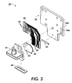
- Fig. 2 is an exploded perspective view of one of the print heads used in the assembly shown in Fig. 1;
- Fig. 3 is an exploded perspective view of the print element shown in Fig. 2;
- Fig. 4 is an exploded perspective view of the ink manifold assembly used in the print element shown in Fig. 3;
- Fig. 5 is an exploded perspective view of the other print head used in the assembly shown in Fig. 1;
- Fig. 6 is an exploded perspective view of the print element shown in Fig. 5;
- Fig. 7 is an exploded perspective view of the ink manifold assembly used in the print element shown in Fig. 6;
- Figs. 8A and 8B are schematic diagrams of methods of using a same type of print element in two different types of printing devices;
- Fig. 9 is a schematic perspective view of three print elements being grouped or ganged together in a staggered or stepped configuration;
- Fig. 10 is an exploded perspective view of an alternate embodiment of a print head having a dual ink manifold assembly; and
- Figs. 11-13 are schematic diagrams of examples of alternate embodiments of how print elements can be grouped.
-
- Referring to Fig. 1, there is shown a perspective view of a
print head assembly 10 incorporating features of the present invention. Although the present invention will be described with reference to the embodiments shown in the drawings, it should be understood that the present invention can be embodied in many alternate forms of embodiments. In addition, any suitable size, shape or type of elements or materials could be used. - The
print head assembly 10 generally comprises acarriage 12 and twoprint heads carriage 12. Thecarriage 12 is intended to be movably mounted on a frame of a printing device, such as a thermal ink jet printer, for reciprocating lateral sliding movement on the frame as is generally known in the art. In this embodiment thefirst print head 14 is intended to be a black ink print head and thesecond print head 16 is intended to be a color ink print head. However, in the alternate embodiments, the print head assembly configuration could be varied, such as a carriage with only a single black ink print head, a carriage with multiple black ink print heads, a carriage with multiple color print heads, or any other suitable configuration. - Referring also to Fig. 2, the
first print head 14 generally comprises ahousing 18, aprint element 20, and aseal member 22. Thehousing 18 is preferably a one-piece molded plastic member. In this embodiment thehousing 18 comprises areceiving area 24, an integrally formedresilient latch 26, substantially open top and front ends, and anaperture 28 extending through the housing. Thereceiving area 24 is suitably sized and shaped to removably receive an ink supply cartridge ortank 30. Thetank 30 can be inserted into and removed from thereceiving area 24 through the substantially open top and front ends of thehousing 18. Thelatch 26 is configured to resiliently snap-lock latch thetank 30 inside thereceiving area 24. Thelatch 26 can deflect in a general cantilever fashion. A user can deflect the top end of thelatch 26 rearward for removing or unlatching thetank 30 from thehousing 18. In alternate embodiments any suitable type of latching or mounting mechanism could be used to fix thetank 30 with thehousing 18. In this embodiment theaperture 28 extends through a comer of thehousing 18; through portions of thebottom wall 32 and theright side wall 34. However, in alternate embodiments the aperture could extend merely through thebottom wall 32 or through any one or more of the side walls of thehousing 18. - Referring also to Fig. 3, the
print element 20 generally comprises aheat sink 36, a printedwiring member 38, a thermalink jet assembly 40, anink manifold assembly 42, afluid seal 44, and afacetape 46. In this embodiment the print elements have thermal ink jet assemblies. However, features of the present invention could be used without a heat sink and with a piezoelectric ink jet assembly, an acoustic ink jet assembly, a thermal wax printer, or any other suitable liquid ink printing device. Theheat sink 36 is preferably a flat one-piece member, such as aluminium. The printedwiring member 38 includes electrically conductive traces on a substrate withcontact pads 48 at one end andcontact areas 50 at an opposite end. The printedwiring member 38 is fixedly attached directly on theheat sink 36 with thecontact pads 48 at a rear end edge and thecontact areas 50 at a bottom end edge. Thus, themember 38 has a general right angle of L-shaped configuration. The rear end of theheat sink 36 and thecontact pads 48 are sized and shaped to be connected to an electrical connector, similar to a card edge connector, such as disclosed in U.S. Patent No.4,934,961, which is hereby incorporated by reference, but as a single row of contacts on one side of the card edge receiving area. However, any suitable electrical connection could be made. Themember 38 also has holes therethrough for mounting posts of theink manifold assembly 42 to extend through. The posts can extend into holes in theheat sink 36 for mounting theink manifold assembly 42 to theheat sink 36. The thermalink jet assembly 40 is fixedly attached to the side of theheat sink 36 at its bottom end edge. Theink jet assembly 40 is also operably connected to thecontact areas 50 of the printedwiring member 38. Thefluid seal 44 covers a side of theink manifold assembly 42 and hasslots 52 for ink to flow from an outlet of theink manifold assembly 42 to theink jet assembly 40. In the embodiment shown, the printedwiring member 38,ink jet assembly 40, andink manifold assembly 42 are mounted to oneside 36a of theheat sink 36. In an alternate embodiment mirror image components of thesemembers opposite side 36b of theheat sink 36. Thus, thecontact pads 48 could be located at a first location (onside 36a) or optimally located at a second different location (onside 36b). In another alternate embodiment, two sets of themembers member 36; one set on eachside - Referring also to Fig. 4, the
ink manifold assembly 42 generally comprises abase member 54, acover 56, and twofilters base member 54 and cover 56 are preferably comprised of molded plastic. Thebase member 54 generally comprises afirst section 62 and asecond section 64. Thefirst section 62 includes mounting post 66 (only one of which is shown), arecess 68 for receiving and supporting theink jet assembly 40, and anoutlet 70 through thefirst section 62. Thesecond section 64 extends generally perpendicularly from thefirst section 62. Thesecond section 64 has an ink well 72 which receives thefirst filter 58 and is in communication with theoutlet 70. Thecover 56 is mounted on thesecond section 64 with thefirst filter 58 being sandwiched therebetween. Thecover 56 includes amount 74 extending upward from its top side. Thesecond filter 60 is mounted inside themount 74. Thesecond filter 60 is a coarser filter then thefirst filter 58. Themount 74 is sized and shaped to extend into a receivinghole 76 in the ink tank 30 (see Fig. 2). Themount 74 is also suitably sized and shaped to have a hose or conduit (not shown) from a different type of ink supply mounted thereon around the outer perimeter of the mount. Themount 74 extends generally parallel relative to theheat sink 36. - In order to form the
first print head 14 theprint element 20 is manufactured and then connected to thehousing 18. Thehousing 18 has mounting posts (not shown) on the exterior of its right side that extend into holes of theheat sink 36 and mount theheat sink 36 on the exterior of the right side of thehousing 18. Theink manifold assembly 42 extends through theaperture 28 into the receivingarea 24. Theseal member 22 is placed against theinterior bottom wall 32 of thehousing 18 with themount 74 extending through the hole 78 (see Fig. 2). Theseal member 22 is preferably comprised of an elastomeric material and includes a resilient upwardly facing ridge 8. Theridge 80 functions as a spring. Theridge 80 is resiliently compressed or deflected when thetank 30 is inserted into the receivingarea 24 and helps to distribute some of the mounting load, from thetank 30 being placed into the receivingarea 24, onto thehousing 18 rather than all of the load being placed against themount 74 and theprint element 20. The spring feature of theridge 80 also biases theink tank 30 towards thelatch 26 to stabily hold thetank 30 with theprint head 14 with minimal forces being exerted against theprint element 20 and the otherwise undesired resultant movement of theink jet assembly 40, during ink tank loading. - Referring to Figs. 1 and 5, the
second print head 16 generally comprises a housing 188, aprint element 120, and aseal member 122. Thehousing 118 is preferably a one-piece molded plastic member. In this embodiment thehousing 118 comprises a receivingarea 124, three integrally formedresilient latches 126, substantially open top and front ends, and anaperture 128 extending through the housing. The receivingarea 124 is suitably sized and shaped to removably receive three ink supply cartridges or tanks similar to theblack ink tank 30, but smaller in width and having color inks. The tanks can be inserted into and removed from the receivingarea 124 through the substantially open top and front ends of thehousing 118. Thelatches 126 are configured to resiliently snap-lock latch the tanks inside the receivingarea 124. Thelatches 126 can deflect in a general cantilever fashion. A user can manually deflect the top end of thelatches 126 rearward for removing or unlatching the tanks from thehousing 118. In alternate embodiments any suitable type of latching or mounting mechanism could be used to fix the tanks with thehousing 118. In this embodiment theaperture 128 extends through a corner of thehousing 118 and through portions of thebottom wall 132 and theleft side wall 133. However, in alternate embodiments the aperture could extend merely through thebottom wall 132 or through any one or more of the side walls of thehousing 118. - Referring also to Fig. 6, the
print element 120 generally comprises aheat sink 136, a printedwiring member 138, a thermalink jet assembly 140, anink manifold assembly 142, afluid seal 144, and afacetape 146. Theheat sink 136 is preferably a flat one-piece member, such as aluminium. Preferably, theheat sink 136 is exactly the same as theheat sink 36, but could be different. The printedwiring member 138 includes electrically conductive traces on a substrate with contact pads at a rear end and contact areas at an opposite bottom end. The printedwiring member 138 is fixedly attached directly on theheat sink 136 with the contact pads at a rear end edge and the contact areas at a bottom end edge. Thus, themember 138 has a general right angle or L- shaped configuration. The rear end of theheat sink 136 and the contact pads of themember 138 are preferably designed to have a card edge type of electrical connector removably mounted thereon similar to theheat sink 36 andcontact pads 48. In an alternate embodiment a single electrical connector can be mounted on the rear end of bothheat sinks member 138 also has holes therethrough for mounting posts of theink manifold assembly 142 to extend through. The posts can extend into holes in thehead sink 136 for mounting theink manifold assembly 142 to theheat sink 136. The thermalink jet assembly 140 is fixedly attached to the side of theheat sink 136 at its bottom end edge. Theink jet assembly 140 is also operably connected to the contact areas of the printedwiring member 138. Thefluid seal 144 covers a side of theink manifold assembly 142 and hasslots 152 for ink to flow from outlets of theink manifold assembly 142 to theink jet assembly 140. - Referring also to Fig. 7, the
ink manifold assembly 142 generally comprises abase member 154, acover 156, and two types offilters base member 154 and cover 156 are preferably comprised of molded plastic. Thebase member 154 generally comprises afirst section 162 and asecond section 164. Thefirst section 162 includes mountingpost 166, arecess 168 for receiving and supporting theink jet assembly 140, and threeoutlets first section 162. Thesecond section 164 extends generally perpendicularly from thefirst section 162 with threeink wells filters 160 and are in communication with the outlets 170. Thecover 156 is mounted on thesecond section 164 with thefilters 160 being sandwiched therebetween. Thecover 156 includes threemounts filters 158 are mounted inside the mounts 174. Thefilters 158 are coarser filters than thefilters 160. The mounts 174 are sized and shaped to extend into a receiving hole in the ink tanks (similar to Fig. 2). The mounts 174 are also suitably sized and shaped to have a hose or conduit (not shown) from a different type of ink supply mounted thereon around the outer perimeter of the mounts. The mounts 174 extends generally parallel relative to theheat sink 136. - In order to form the
second print head 16 theprint element 120 is manufactured and then connected to thehousing 118. Thehousing 118 has mountingposts 119 on the exterior of itsleft side 133 that extend into holes of theheat sink 136 and mount theheat sink 136 to the exterior of the left side of thehousing 118. Theink manifold assembly 142 extends through theaperture 128 into the receivingarea 124. Theseal member 122 is placed against the interior bottom wall of thehousing 118 with the mounts 174 extending throughholes 178. Theseal member 122 is preferably comprised of an elastomeric material and includes a resilient upwardly facingridge 180. Theridge 180 functions as a spring. Theridge 180 is resiliently compressed or deflected when the tanks are inserted into the receivingarea 124 and helps to distribute some of the mounting load, from the tanks being placed into the receivingarea 124, onto thehousing 118 rather than all of the load being placed against the mounts 174 and theprint element 120. The spring feature of theridge 180 also biases the ink tanks towards thelatches 126 to stabily hold the tanks with theprint head 16 with minimal forces being exerted against theprint element 120 and the otherwise undesired resultant movement of theink jet assembly 140, during ink tank loading. In this embodiment thehousing 118 also hasnotches 129 in itsright side 134. Thedistal end 165 of themanifold assembly 142 hadprojections 167. When theprint element 120 is mounted to thehousing 118, theprojections 167 extend into thenotches 129 to stabily mount thedistal end 165 to thehousing 118. - Referring back to Fig. 1, the
first print head 14 is positioned on the left side of thecarriage 12 and thesecond print head 16 is positioned on the right side of thecarriage 12. The twoheat sinks housings section 13 of thecarriage 12. The heat sinks 36, 136 can be directly connected to each other or, alternatively, connected to a portion of thecarriage 12 which is sandwiched directly between the twoheat sinks print elements tank receiving housings print elements carriage 12 to provide a precise offset D, such as the length of 110 ink jets, between the front ends of theink jet assemblies color print elements 120 could be used in a single device. - Referring now to Fig. 8A, the
print element 20 can be used in a first type ofprinting device 200 without connecting theprint element 20 to thehousing 18. For example, the first type ofprinting device 200 could have anink supply 202 which is spaced from theprint element 20 and connected to themount 74 by a supply conduit ortube 204. Fig. 8B illustrates that the same type ofprint element 20 can be mounted with thehousing 18 atstep 206 to form theprint head 14 which is subsequently used to form the second different type ofprinting device 208 which can use rechargeable ink tanks mounted directly on themount 74. During the assembly process at the manufacturing facility, theprint head 20 can be manufactured on an assembly line and, with the additional optional additional step of mounting thehousing 18 to theprint element 20, the single assembly line can manufacture two different types of components for two different types of printing devices having different types of ink supply systems, but which use the same type of print elements. The present invention, by keeping the ink manifold assembly only on the print element and not using thehousing 18 as part of the ink manifold, allows the print element to be tested and discarded if defective before connected to thehousing 18. Thus, if the print element is defective, ahousing 18 does not also need to be discarded because the housing has not been connected to the print element yet. The present invention could also include the print element being permanently attached to an ink supply with an integral housing to form a unitary ink supply and print head cartridge similar to the cartridge disclosed in U.S. Patent No. 5,519,425. The same multiple use/configuration described above for the blackink print element 20 is equally applicable to the colorink print element 120. - Referring now to Fig. 9, three of the
print elements 20 are shown in a gang or grouped configuration. The threeprint elements 20 are mounted on a carriage 12' with the leading ends of their ink jet assemblies offset in a stepped configuration from the front edge of the carriage 12'. Themounts 74 would be connected to a single black ink source by three conduits (not shown). This type of ganging of theprint elements 20 could be used in a device such as a plotter that prints on very large print medium, wherein ganging of the print elements in a stepped configuration can cover a larger area of the print medium in a single pass and thereby speed up printing. In alternate embodiments more or less than three of the same types of print elements can be ganged together, multiple gangs could be mounted on the same carriage, a print element and a gang or gangs of print elements could be on the same carriage, or multiple sets of one or more gangs of print elements could be on the same carriage. Any suitable grouping or configurations could be provided. Multiple carriages could also be provided. Some examples of these alternate embodiments are shown in Figs. 11, 12, and 13. In Fig. 11, for example, thecarriage 400 comprises three assemblies organgs gangs print elements print elements gang 402 could be connected to one color ink sources, the print elements ingang 404 could be connected to a different color ink source, and the print elements ingang 406 could be connected to another different color ink source. Fig. 12 shows another example wherein acarriage 420 has an assembly organg 422 or threeprint elements print element 428 not directly ganged with theassembly 422. Fig. 13 shows another example wherein thecarriage 430 has twoassemblies subassemblies - Referring now to Fig. 10 an alternate embodiment of the black
ink print head 300 is shown. In this embodiment theprinthead 300 includes a combined ink tank receiving housing andink manifold member 302, aheat sink 304, amanifold cover 306, acoarse filter 308, aseal 310, anink jet assembly 312, a printedwiring member 314, afine filter 316, amanifold filter cover 318, and afaceplate 320. In this embodiment theink tank 30 is mounted in themember 302 and ink is conduited through themember 302, to thefine filter 316 andmanifold filter cover 318 on the opposite side of theheat sink 304. The ink is then delivered to theink jet assembly 312. Theink jet assembly 312 is located on the opposite side of theheat sink 304 from themember 302. Thus, forces from loading theink tank 30 into themember 302 are not directly transferred to theink jet assembly 312. In addition, with this design heat can be stored in the ink and removed with drop ejection. With this type of design the ink jet assemblies could be located almost adjacent each other with only the manifold filter covers therebetween. This embodiment describes an ink jet cartridge which is made by joining twomanifolds first manifold 318 can be placed on each die and different versions of thesecond manifold 302 can be designed for different product families. Also, the precision molded features can be contained in the smaller first manifold, thus providing tolerance relief and wider materials choice for the second larger manifold. An advantage is the ability to print test the die with the first manifold to find rejects before finally assembly begins. - In the two manifold design, the ink tanks are inserted into the port manifold. The printer carriage rigidly holds the heat sink on the datums. Previous designs place the manifold against the die and heat sink with two point contact on the fluid seal and the third point on the manifold. This ensures that the fluid seal is properly compressed against the die and therefore provides a good seal. Ink tank insertion therefore applies stress to the fluid seal bond. The dual manifold design isolates the ink tank insertion to the heat sink side opposite the
die 312 and, therefore, none of the ink tank insertion forces are applied to the fluid seal. Also, since the fluid seal compression is not an issue with the port manifold, the port manifold can be grounded against the heat sink creating a more rigid package. - Due to the fine filter manifold small size, the part can be placed more accurately with smaller tolerances in the critical fluid seal area. The port manifold is added after the print element assembly is cured and therefore the port manifold does not see the high temperature cure cycles.
- The ink jet fluid path has many requirements such as ink compatibility, flatness, low thermal expansion, and high deformation temperature that severely limit the material selection. The single manifold approach can require a large housing to be made from an expensive material that is difficult to process, which makes the molds extremely expensive and difficult to maintain. The overall part size makes it difficult to maintain the critical features. The dual manifold approach passes most of the requirements to the fine filter manifold. This manifold has the flatness and low thermal expansion requirements in the fluid seal area, and goes through the high temperatures required to cure the fluid seal. The two manifold approach actually eases the design requirements because the part is small and therefore a lot easier to hold the tight tolerances. The port manifold only has the ink compatibility requirement, and therefore has more material options, including materials that are 4-5 times cheaper per round and a lot easier to process making the mold cheaper.
- The print element assembly can be print tested as a stand alone unit. This has many advantages. First, if there is a failure and the unit is discarded, only the cost of the print element is lost, not the entire cost of the print cartridge. Second, after the print test, only the print element is required to be cleaned. The additional wetted area of the port manifold is not inked and therefore does not require cleaning. The fine filter ports also provide a convenient location for the print tester to connect to.
- The present invention allows for a print cartridge design that is flexible enough to have either an onboard reservoir, a replaceable ink tank, or an external supply would have a high degree of reuse potential and synergy with a number of different products. An additional variation could allow for a head that has an integral ink supply to alternately accept an external ink supply.
- The ultimate engineering feat would be to design a part that works in many applications. The proposal outlined here is to have a basic print element unit that can accept permanent ink tanks, removable ink tanks, or an external (perhaps tube fed) supply. The base printhead could be the same across all these product families, using common tooling.
- The basic housing would incorporate all of the features necessary to attach to the print transducer as well as the required electrical interconnect. The lowest common ink delivery would be incorporated into this part. Through either mold inserts or separate parts, the options for the different feed mechanisms would be incorporated. The datum structures and tooling features would be developed off the base part so that the ink delivery variation would not impact the manufacture of the part.
- A variation of this implementation, which is independent of it, is to allow for an ink tank supplied with ink to have an off head external supply connected to it. For example, a vent in the ink tank could allow for a feature to have a hose fitting from an external reservoir inserted or connected to it. This would allow customers with large graphics requirements to print large jobs without printhead replacement.
Claims (9)
- A print element (120) comprising:an ink delivery nozzle (140);an electrical conductor (138) connected to the ink delivery nozzle; andan ink conduiting member (142) connected to the ink delivery nozzle (140), the conduiting member comprising a connection system (172a, 172b, 172c) for alternatively connecting the conduiting member (142) to at least two different sources of ink.
- A print element as in claim 1, further comprising a heat sink (136), wherein the ink delivery nozzle (140) comprises a thermal ink jet assembly connected to the heat sink (136).
- A print element as in claim 2, comprising an electrical printed wiring member (138) connected to the thermal ink jet assembly, wherein the electrical printed wiring (138) member comprises the electrical conductor.
- A print element as in claim 1, 2 or 3, wherein the connection system is suitably sized and shaped to connect to a direct umbilical tube connection to the source of ink, or to a separable ink tank, or to an inseparable reservoir, or to a refillable ink reservoir, or to a refillable ink reservoir.
- A print element comprising:an ink delivery nozzle array;electrical conductors connected to the nozzle array; anda manifold assembly mounted to the nozzle array, the manifold assembly having a first mount for removably connecting a first source of ink to the manifold assembly and a first outlet to the nozzle array.
- A print element comprising:wherein the electrical conductors include contact areas located at a first location or optionally located at a second different location.an ink delivery nozzle array;electrical conductors connected to the ink delivery nozzle array; andan ink conduiting member connected to the ink delivery nozzle array,
- A method of manufacturing ink jet printing components comprising steps of:wherein the print element can be assembled in a first type of printing device without the print head housing and, a combined assembly of the print element and the print head housing can be assembled in a second type of printing device.assembling a print element comprising connecting an ink delivery nozzle array to an ink manifold assembly; andoptionally connecting the print element to a print head housing, the print head housing having a receiving area for removably receiving an ink tank,
- A method of manufacturing an ink jet printing element comprising steps of:providing an ink jet manifold assembly having a first connector for alternatively connecting the ink manifold assembly to at least two different sources of ink;connecting an ink delivery nozzle array to the ink manifold assembly; andconnecting electrical conductors to the nozzle array.
- A method of manufacturing an ink jet printing device comprising steps of:connecting multiple ink jet printing elements to each other in at least one first gang assembly, the multiple printing elements being connected to similar ink sources; andconnecting at least one other ink jet printing element to the at least one first gang assembly as an at least one second gang assembly, the at least one other ink jet printing element being connected to a separate ink source then the ink sources of the at least one first gang assembly.
Applications Claiming Priority (2)
| Application Number | Priority Date | Filing Date | Title |
|---|---|---|---|
| US382886 | 1982-05-28 | ||
| US09/382,886 US6655785B1 (en) | 1999-08-25 | 1999-08-25 | Print element and method for assembling a print head |
Publications (3)
| Publication Number | Publication Date |
|---|---|
| EP1078769A2 true EP1078769A2 (en) | 2001-02-28 |
| EP1078769A3 EP1078769A3 (en) | 2002-01-02 |
| EP1078769B1 EP1078769B1 (en) | 2008-03-19 |
Family
ID=23510820
Family Applications (1)
| Application Number | Title | Priority Date | Filing Date |
|---|---|---|---|
| EP00307028A Expired - Lifetime EP1078769B1 (en) | 1999-08-25 | 2000-08-16 | Print element and method for assembling a print head |
Country Status (4)
| Country | Link |
|---|---|
| US (1) | US6655785B1 (en) |
| EP (1) | EP1078769B1 (en) |
| JP (1) | JP2001063032A (en) |
| DE (1) | DE60038342T2 (en) |
Cited By (7)
| Publication number | Priority date | Publication date | Assignee | Title |
|---|---|---|---|---|
| US7156510B2 (en) | 2003-07-30 | 2007-01-02 | Fuji Xerox Co., Ltd. | Devices for dissipating heat in a fluid ejector head and methods for making such devices |
| US7261389B2 (en) * | 2003-11-26 | 2007-08-28 | Fuji Xerox Co., Ltd. | Systems and methods for dissipating heat into a fluid ejector carriage device |
| WO2011123294A1 (en) * | 2010-03-31 | 2011-10-06 | East Kodak Company | Holding receptacle for inkjet tank |
| WO2011123260A1 (en) * | 2010-03-31 | 2011-10-06 | Eastman Kodak Company | Inkjet printer |
| WO2011123434A1 (en) * | 2010-03-31 | 2011-10-06 | Eastman Kodak Company | Ink passageways connecting inlet ports and chambers |
| WO2011123258A1 (en) * | 2010-03-31 | 2011-10-06 | Eastman Kodak Company | Snap-in die mount assembly for inkjet printhead |
| WO2016205168A2 (en) * | 2015-06-15 | 2016-12-22 | Videojet Technologies Inc. | Module for ink jet printer |
Families Citing this family (4)
| Publication number | Priority date | Publication date | Assignee | Title |
|---|---|---|---|---|
| JP4222078B2 (en) * | 2003-03-26 | 2009-02-12 | ブラザー工業株式会社 | Recording device |
| US20060012634A1 (en) * | 2004-07-15 | 2006-01-19 | Squie Roger W | Print cartridge adapter |
| DE102006036716B3 (en) * | 2006-06-02 | 2007-09-27 | Artech Gmbh Design + Production In Plastic | Printer e.g. inkjet printer, retrofitting device, has cartridge retaining device to retain replaceable original ink cartridges, and locking pin to lock fastener in fastening position when insert-ink cartridge is attached in retaining device |
| CN111619248B (en) * | 2020-06-05 | 2022-03-25 | 真益电子(深圳)有限公司 | Portable high-speed thermal printer |
Citations (4)
| Publication number | Priority date | Publication date | Assignee | Title |
|---|---|---|---|---|
| US4695854A (en) | 1986-07-30 | 1987-09-22 | Pitney Bowes Inc. | External manifold for ink jet array |
| US4934961A (en) | 1988-12-21 | 1990-06-19 | Burndy Corporation | Bi-level card edge connector and method of making the same |
| US5297336A (en) | 1992-04-02 | 1994-03-29 | Xerox Corporation | Process for making an ink manifold having elastomer channel plate for ink jet printhead |
| US5519425A (en) | 1993-11-15 | 1996-05-21 | Xerox Corporation | Ink supply cartridge for an ink jet printer |
Family Cites Families (29)
| Publication number | Priority date | Publication date | Assignee | Title |
|---|---|---|---|---|
| US4633274A (en) | 1984-03-30 | 1986-12-30 | Canon Kabushiki Kaisha | Liquid ejection recording apparatus |
| JP3066867B2 (en) | 1988-10-31 | 2000-07-17 | キヤノン株式会社 | Inkjet printer, recording head, ink cassette and sales set for inkjet recording |
| JPH02198881A (en) * | 1989-01-27 | 1990-08-07 | Shimadzu Corp | Printer |
| ES2081920T3 (en) | 1989-01-28 | 1996-03-16 | Canon Kk | APPARATUS FOR INK JETS AND HEAD FOR INK JETS. |
| US4940998A (en) * | 1989-04-04 | 1990-07-10 | Hewlett-Packard Company | Carriage for ink jet printer |
| IT1232551B (en) * | 1989-07-13 | 1992-02-19 | Olivetti & Co Spa | PRINT HEAD FOR A INK-JET THERMAL PRINTER |
| WO1991008112A1 (en) | 1989-11-29 | 1991-06-13 | Siemens Aktiengesellschaft | Printing head for ink-jet printer |
| JP2962044B2 (en) * | 1992-05-29 | 1999-10-12 | 富士ゼロックス株式会社 | Ink tank, inkjet cartridge, and inkjet recording device |
| JP3585939B2 (en) * | 1993-04-19 | 2004-11-10 | キヤノン株式会社 | Recording head unit and ink jet recording apparatus using the unit |
| JPH0725110A (en) * | 1993-07-09 | 1995-01-27 | Fuji Xerox Co Ltd | Ink jet recorder |
| JP3267398B2 (en) * | 1993-08-02 | 2002-03-18 | キヤノン株式会社 | Inkjet head assembly and method of assembling the inkjet head assembly |
| JP3133906B2 (en) * | 1993-08-19 | 2001-02-13 | キヤノン株式会社 | Ink tank cartridge |
| JPH0781049A (en) * | 1993-09-16 | 1995-03-28 | Canon Inc | Ink jet recording apparatus and data processing apparatus equipped therewith |
| US5565900A (en) * | 1994-02-04 | 1996-10-15 | Hewlett-Packard Company | Unit print head assembly for ink-jet printing |
| JPH07246713A (en) * | 1994-03-09 | 1995-09-26 | Canon Inc | Image forming device |
| US5771052A (en) * | 1994-03-21 | 1998-06-23 | Spectra, Inc. | Single pass ink jet printer with offset ink jet modules |
| JP3372701B2 (en) * | 1994-05-30 | 2003-02-04 | キヤノン株式会社 | Ink jet recording device |
| US5659345A (en) * | 1994-10-31 | 1997-08-19 | Hewlett-Packard Company | Ink-jet pen with one-piece pen body |
| US5739830A (en) * | 1995-01-05 | 1998-04-14 | Xerox Corporation | Monolithic printheads for ink jet printing apparatus |
| US6130695A (en) * | 1995-04-27 | 2000-10-10 | Hewlett-Packard Company | Ink delivery system adapter |
| US6039441A (en) * | 1995-09-28 | 2000-03-21 | Fuji Xerox Co., Ltd. | Ink jet recording unit |
| US6000789A (en) * | 1996-04-23 | 1999-12-14 | Fuji Xerox Co., Ltd. | Printer and ink tank |
| JP3171102B2 (en) * | 1996-04-23 | 2001-05-28 | 富士ゼロックス株式会社 | Printer and ink tank |
| US5959647A (en) * | 1996-04-29 | 1999-09-28 | Hewlett-Packard Company | Technique for converting single cartridge monochrome printer to multi-cartridge color inkjet printer |
| JP3617213B2 (en) * | 1996-10-01 | 2005-02-02 | 富士ゼロックス株式会社 | Ink tank, ink jet recording unit, and ink jet recording apparatus |
| JPH1177989A (en) * | 1997-09-10 | 1999-03-23 | Toshiba Tec Kk | Ink jet printer head and its manufacture |
| US6224192B1 (en) * | 1998-10-06 | 2001-05-01 | Hewlett-Packard Company | Inkjet printing systems using a modular print cartridge assembly |
| US6343848B2 (en) * | 1999-01-19 | 2002-02-05 | Xerox Corporation | Method and apparatus for transferring heat from a thermal inkjet printhead substrate using a heat sink |
| US6206510B1 (en) * | 1999-04-22 | 2001-03-27 | Hewlett-Packard Company | Method and apparatus for adapting an ink jet printing system for receiving an alternate supply of ink |
-
1999
- 1999-08-25 US US09/382,886 patent/US6655785B1/en not_active Expired - Fee Related
-
2000
- 2000-08-16 EP EP00307028A patent/EP1078769B1/en not_active Expired - Lifetime
- 2000-08-16 DE DE60038342T patent/DE60038342T2/en not_active Expired - Lifetime
- 2000-08-25 JP JP2000254863A patent/JP2001063032A/en active Pending
Patent Citations (4)
| Publication number | Priority date | Publication date | Assignee | Title |
|---|---|---|---|---|
| US4695854A (en) | 1986-07-30 | 1987-09-22 | Pitney Bowes Inc. | External manifold for ink jet array |
| US4934961A (en) | 1988-12-21 | 1990-06-19 | Burndy Corporation | Bi-level card edge connector and method of making the same |
| US5297336A (en) | 1992-04-02 | 1994-03-29 | Xerox Corporation | Process for making an ink manifold having elastomer channel plate for ink jet printhead |
| US5519425A (en) | 1993-11-15 | 1996-05-21 | Xerox Corporation | Ink supply cartridge for an ink jet printer |
Cited By (15)
| Publication number | Priority date | Publication date | Assignee | Title |
|---|---|---|---|---|
| US7156510B2 (en) | 2003-07-30 | 2007-01-02 | Fuji Xerox Co., Ltd. | Devices for dissipating heat in a fluid ejector head and methods for making such devices |
| US7261389B2 (en) * | 2003-11-26 | 2007-08-28 | Fuji Xerox Co., Ltd. | Systems and methods for dissipating heat into a fluid ejector carriage device |
| WO2011123294A1 (en) * | 2010-03-31 | 2011-10-06 | East Kodak Company | Holding receptacle for inkjet tank |
| WO2011123260A1 (en) * | 2010-03-31 | 2011-10-06 | Eastman Kodak Company | Inkjet printer |
| WO2011123434A1 (en) * | 2010-03-31 | 2011-10-06 | Eastman Kodak Company | Ink passageways connecting inlet ports and chambers |
| WO2011123258A1 (en) * | 2010-03-31 | 2011-10-06 | Eastman Kodak Company | Snap-in die mount assembly for inkjet printhead |
| US8256876B2 (en) | 2010-03-31 | 2012-09-04 | Eastman Kodak Company | Ink passageways connecting inlet ports and chambers |
| US8317300B2 (en) | 2010-03-31 | 2012-11-27 | Eastman Kodak Company | Inkjet printer |
| US8322834B2 (en) | 2010-03-31 | 2012-12-04 | Eastman Kodak Company | Snap-in die mount assembly for inkjet printhead |
| CN102834268A (en) * | 2010-03-31 | 2012-12-19 | 伊斯曼柯达公司 | Ink passageways connecting inlet ports and chambers |
| WO2016205168A2 (en) * | 2015-06-15 | 2016-12-22 | Videojet Technologies Inc. | Module for ink jet printer |
| WO2016205168A3 (en) * | 2015-06-15 | 2017-03-30 | Videojet Technologies Inc. | Module for ink jet printer |
| CN107921782A (en) * | 2015-06-15 | 2018-04-17 | 录象射流技术公司 | Module for ink-jet printer |
| US10399348B2 (en) | 2015-06-15 | 2019-09-03 | Videojet Technologies Inc. | Module for ink jet printer |
| CN107921782B (en) * | 2015-06-15 | 2020-09-01 | 录象射流技术公司 | Module for ink-jet printer |
Also Published As
| Publication number | Publication date |
|---|---|
| EP1078769B1 (en) | 2008-03-19 |
| EP1078769A3 (en) | 2002-01-02 |
| DE60038342T2 (en) | 2009-03-12 |
| JP2001063032A (en) | 2001-03-13 |
| US6655785B1 (en) | 2003-12-02 |
| DE60038342D1 (en) | 2008-04-30 |
Similar Documents
| Publication | Publication Date | Title |
|---|---|---|
| JP3542389B2 (en) | Parallel printing apparatus and manufacturing method thereof | |
| US5515091A (en) | Replaceable ink tank | |
| EP0578329B1 (en) | Ink jet recording head and ink jet apparatus having same | |
| JP3420637B2 (en) | Modular carriage assembly and carriage for inkjet printer | |
| JP4689927B2 (en) | Method for adjusting the position of a plurality of print heads with respect to an ink jet printer | |
| EP1078769B1 (en) | Print element and method for assembling a print head | |
| EP0418817B1 (en) | Ink jet recording head and ink jet recording apparatus using same | |
| US7452060B2 (en) | Ink-jet printing unit having plate-stacked type printing head and method of producing the same | |
| US6824243B2 (en) | Liquid jet print head and liquid jet printing apparatus | |
| RU2248886C2 (en) | Methods for mounting jet printing cartridge having lowe shape coefficient, in carriage with dimensions for cartridge, having large shape coefficient | |
| JP5505595B2 (en) | Liquid jet head unit and manufacturing method thereof | |
| US6402310B1 (en) | Ink jet cartridge, ink jet apparatus, and manufacture method of ink jet cartridge | |
| JP2003145791A (en) | Ink jet printer head | |
| US7156510B2 (en) | Devices for dissipating heat in a fluid ejector head and methods for making such devices | |
| US7735985B2 (en) | Cartridge holder | |
| JP2003211700A (en) | Inkjet recorder | |
| US5739830A (en) | Monolithic printheads for ink jet printing apparatus | |
| US8590156B2 (en) | Method for assembling an inkjet printhead | |
| JP2003011382A (en) | Inkjet recorder | |
| US8322834B2 (en) | Snap-in die mount assembly for inkjet printhead | |
| US7559620B2 (en) | Printhead assembly having replaceable printhead | |
| WO2022268427A1 (en) | Thermal regulation in long inkjet printhead | |
| JP2022108819A (en) | Liquid jet device, and method for fixing liquid jet head |
Legal Events
| Date | Code | Title | Description |
|---|---|---|---|
| PUAI | Public reference made under article 153(3) epc to a published international application that has entered the european phase |
Free format text: ORIGINAL CODE: 0009012 |
|
| AK | Designated contracting states |
Kind code of ref document: A2 Designated state(s): DE FR GB Kind code of ref document: A2 Designated state(s): AT BE CH CY DE DK ES FI FR GB GR IE IT LI LU MC NL PT SE |
|
| AX | Request for extension of the european patent |
Free format text: AL;LT;LV;MK;RO;SI |
|
| RIC1 | Information provided on ipc code assigned before grant |
Free format text: 7B 41J 2/175 A, 7B 41J 25/34 B |
|
| PUAL | Search report despatched |
Free format text: ORIGINAL CODE: 0009013 |
|
| AK | Designated contracting states |
Kind code of ref document: A3 Designated state(s): AT BE CH CY DE DK ES FI FR GB GR IE IT LI LU MC NL PT SE |
|
| AX | Request for extension of the european patent |
Free format text: AL;LT;LV;MK;RO;SI |
|
| 17P | Request for examination filed |
Effective date: 20020702 |
|
| AKX | Designation fees paid |
Free format text: DE FR GB |
|
| 17Q | First examination report despatched |
Effective date: 20050707 |
|
| GRAP | Despatch of communication of intention to grant a patent |
Free format text: ORIGINAL CODE: EPIDOSNIGR1 |
|
| GRAS | Grant fee paid |
Free format text: ORIGINAL CODE: EPIDOSNIGR3 |
|
| GRAA | (expected) grant |
Free format text: ORIGINAL CODE: 0009210 |
|
| AK | Designated contracting states |
Kind code of ref document: B1 Designated state(s): DE FR GB |
|
| REG | Reference to a national code |
Ref country code: GB Ref legal event code: FG4D |
|
| RIN1 | Information on inventor provided before grant (corrected) |
Inventor name: HILTON, BRIAN S. Inventor name: SOBON, ARTHUR J. Inventor name: MOORE, STEVEN R. Inventor name: DERLETH, DAVID S. Inventor name: KEEFE, RICHARD C. |
|
| REF | Corresponds to: |
Ref document number: 60038342 Country of ref document: DE Date of ref document: 20080430 Kind code of ref document: P |
|
| ET | Fr: translation filed | ||
| PLBE | No opposition filed within time limit |
Free format text: ORIGINAL CODE: 0009261 |
|
| STAA | Information on the status of an ep patent application or granted ep patent |
Free format text: STATUS: NO OPPOSITION FILED WITHIN TIME LIMIT |
|
| 26N | No opposition filed |
Effective date: 20081222 |
|
| PGFP | Annual fee paid to national office [announced via postgrant information from national office to epo] |
Ref country code: DE Payment date: 20140722 Year of fee payment: 15 |
|
| PGFP | Annual fee paid to national office [announced via postgrant information from national office to epo] |
Ref country code: FR Payment date: 20140822 Year of fee payment: 15 Ref country code: GB Payment date: 20140725 Year of fee payment: 15 |
|
| REG | Reference to a national code |
Ref country code: DE Ref legal event code: R119 Ref document number: 60038342 Country of ref document: DE |
|
| GBPC | Gb: european patent ceased through non-payment of renewal fee |
Effective date: 20150816 |
|
| REG | Reference to a national code |
Ref country code: FR Ref legal event code: ST Effective date: 20160429 |
|
| PG25 | Lapsed in a contracting state [announced via postgrant information from national office to epo] |
Ref country code: DE Free format text: LAPSE BECAUSE OF NON-PAYMENT OF DUE FEES Effective date: 20160301 Ref country code: GB Free format text: LAPSE BECAUSE OF NON-PAYMENT OF DUE FEES Effective date: 20150816 |
|
| PG25 | Lapsed in a contracting state [announced via postgrant information from national office to epo] |
Ref country code: FR Free format text: LAPSE BECAUSE OF NON-PAYMENT OF DUE FEES Effective date: 20150831 |