EP1084357B1 - Dual-safety valve - Google Patents
Dual-safety valve Download PDFInfo
- Publication number
- EP1084357B1 EP1084357B1 EP99936414A EP99936414A EP1084357B1 EP 1084357 B1 EP1084357 B1 EP 1084357B1 EP 99936414 A EP99936414 A EP 99936414A EP 99936414 A EP99936414 A EP 99936414A EP 1084357 B1 EP1084357 B1 EP 1084357B1
- Authority
- EP
- European Patent Office
- Prior art keywords
- valve
- valve disc
- disc
- closing spring
- dual safety
- Prior art date
- Legal status (The legal status is an assumption and is not a legal conclusion. Google has not performed a legal analysis and makes no representation as to the accuracy of the status listed.)
- Expired - Lifetime
Links
Images


Classifications
-
- F—MECHANICAL ENGINEERING; LIGHTING; HEATING; WEAPONS; BLASTING
- F16—ENGINEERING ELEMENTS AND UNITS; GENERAL MEASURES FOR PRODUCING AND MAINTAINING EFFECTIVE FUNCTIONING OF MACHINES OR INSTALLATIONS; THERMAL INSULATION IN GENERAL
- F16K—VALVES; TAPS; COCKS; ACTUATING-FLOATS; DEVICES FOR VENTING OR AERATING
- F16K1/00—Lift valves or globe valves, i.e. cut-off apparatus with closure members having at least a component of their opening and closing motion perpendicular to the closing faces
- F16K1/32—Details
- F16K1/34—Cutting-off parts, e.g. valve members, seats
- F16K1/44—Details of seats or valve members of double-seat valves
- F16K1/443—Details of seats or valve members of double-seat valves the seats being in series
Definitions
- the invention relates to a double safety valve with two housed in a housing valves, both of which are axially slidable valve plate arranged coaxially with each other are and in each case by an axial movement in the opening direction against the spring pressure of a first and a second Lift the closing spring from its respective valve seat, with the in the flow direction of the double safety solenoid valve second valve plate associated second closing spring on Housing is supported and wherein the first valve plate in Opening direction with the second valve disc motion coupled is, which has an armature as an actuator.
- Such a double safety valve is for example become known by DE-A-195 25 384.
- Such double safety valves especially as safety solenoid valves used at the gas inlet side of gas heat generators.
- valve plates are each Part of two independent control elements, of which the second is guided in the first axially displaceable.
- the Both control elements are powered by a common magnetic drive each against the effect.opened a closing spring, wherein when switching off the magnet, the two closing springs the closing stroke of the two valve discs from each other perform completely independently. This can be the security requirement be met at gas safety valves.
- a safety valve at the connection end of a gas pipe known.
- the in the gas pipe prevailing gas pressure is sealed by two valve bodies, each with its own valve seat interact.
- the closing spring of the first valve body is on the housing and the closing spring of the second valve body at the first Valve body supported.
- this object is equally surprising solved in a simple and effective way that the first closing spring on the second valve disc or on Magnetic armature is supported and that the magnet armature inside a guide element of the first valve disc axially slidably guided.
- first valve plate on the second valve plate or guided axially displaceable on the armature is the first valve plate on the second valve plate or guided axially displaceable on the armature. It is in an embodiment of this development provided that the first valve plate relative to the second valve plate, e.g. is sealed by an O-ring or a lip seal.
- first valve disk motion-coupled with the second valve disc in the opening direction is. This is done with the second valve plate at the same time also the first valve disk from the respective valve seat lifted. In the closing direction both valve disks however, not motion coupled to complete them independently of each other can perform their Scheller. For this, e.g. the first valve plate or its actuator the second valve plate or the armature in the opening direction behind or overlap. The first valve plate is then after a relative stroke of, for example, approx. 1 mm from the second valve disc in the opening direction.
- Double safety valve in which the first valve disc, from Magnet armature radially spaced, by being a hollow armature trained actuator is guided, this allows Training a smaller size and also a variety of constructive possibilities, especially in the Spring design or when applying force.
- the second Closing spring can e.g. between the two control elements, preferably in an annular gap, or in an opening direction be arranged open aperture of the magnet armature.
- the first valve disc surrounds the second valve disc.
- the valve seats of two valve disc combined to form a common valve seat are, which surrounds the only valve opening.
- double safety valve no longer need two valve seats with high Time and effort are processed, but only one single valve seat. The mounting of the device becomes easier because the parts are no longer brought to two seats and a smaller device is easier to handle.
- the housing of the two Valves preferably as a die-cast or by a Extruded profile formed.
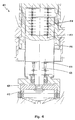
- Fig. 1 denotes a double safety valve
- the two valves connected in series 2 and 3 are housed in a common housing 4 .
- This housing 4 is divided by a valve opening 5 in a gas inlet space 6 and a gas outlet space 7 , wherein the valve opening 5 is surrounded by a valve seat 8 .
- the input-side first (outer) valve 2 consists of an annular first (outer) valve disk 9 , an associated with the valve head 9 actuator (hollow armature or sleeve) 10 and a first (outer) closing spring 11.
- the output side second (inner) valve 3 consists from an annular first (inner) valve disk 12 , a magnet armature 13 connected to this valve disk 12 and a second (inner) closing spring 14 .
- the two valves 2, 3 and their valve disks 9, 12 are arranged coaxially relative to one another with respect to a common axis 15 , the outer valve disk 9 surrounding the inner valve disk 12 in an annular manner.
- the valve seat 8 serves with its contact surface 8a (FIG. 2) as a common valve seat for both valve disks 9, 12, which in each case lift off the common valve seat 8 by an axial movement in the opening direction 16 .
- To open the two valves 2, 3 is a common magnetic drive 17 with a solenoid 18 and a guide opening 19 , in which the adjusting element 10 is guided axially displaceable.
- the magnet armature 13 is in turn guided axially displaceably in the adjusting element 10, wherein the cup-shaped adjusting element 10 engages behind the armature 13 in the opening direction 16 and is thus coupled with the magnet armature 13 in the opening direction 16.
- the outer closing spring 11 is supported on the housing 4, while the inner closing spring 14 is supported inside the adjusting element 10 on a circumferential shoulder 20 .
- the outer closing spring 11 therefore brings the force for closing both valve disks 9, 12 and the valves 2, 3, respectively. Both valves therefore, since the inner closing spring 14 is supported against the outer closing spring 11 and this is relieved.
- the inner closing spring 14 is designed so that anyway there is still enough power, even in this case inner valve plate 12 and the inner valve 3 to close.
- the inner valve 3 closes when the outer valve 2 closes (stroke of the inner valve disk 12 relative to the outer valve plate 9: 1 mm) and if that Do not close outer valve 2 due to malfunction should (stroke of the inner valve disc 12 relative to the outer Valve disc 9: nominal stroke + 1 mm).
- To open the two valves 2, 3 is compared to known double safety valves with axially successively arranged valves despite the stronger outer closing spring 11 no stronger magnet required, since the outer closing spring 11, as described above, is relieved of the inner closing spring 14.
- a Y-shaped control element 21 is provided, which passes through the valve opening 5 and is axially displaceable.
- the actuator 21 is adjusted according to a desired outlet pressure in the gas outlet 7.
- the adjusting element 21 with its free plate-shaped end also bears against the flat contact surface 8a of the common valve seat 8, the diameter of the plate-shaped end being greater than the diameter of the valve opening 5.
- the double safety valve 101 shown in Fig. 3 differs in that the inner closing spring 114 is housed within an opening (blind bore) 123 in the armature 113 and at one end to the armature 113 and the other end at the bottom 124 of the cup-shaped control element 110 is supported.
- the advantage of depending supported closing springs 111 and 114 is that in the case of jamming of the armature 113 in the actuator 110, the strong outer closing spring 111, which has previously stored the closing force for the two valve plates 109, 112 , the remaining intact outer valve plate 109 closes ,
- the common valve seat 108 has no common flat contact surface for both valve plates 109 and 112, but the two contact surfaces 108a and 108b are arranged axially offset from one another.
- the outer abutment surface 108a is pointed and the elastomeric sealing means of the outer valve disc 109 interacting with this abutment surface 108a is flat.
- the inner contact surface 108b which simultaneously serves as a contact surface for the adjusting element 21, flat and the cooperating with this contact surface 108b elastomeric sealing means of the inner valve disk 112 is pointed.
- a Dissesprüfö réelle 135 is provided on the common valve seat 108, which leads into the annular space between the two valve plates 109, 112, so that a leak test of the double seat valve 101 is possible.
- the outer closing spring 411 seated on the guide section 425 for the outer valve disk 409 is supported on the latter and on the magnet armature 413 .
- the inner closing spring 414 for the inner valve plate 412 must be about twice as strong, since the two closing springs 411, 414 mutually support.
- a pendulum of the outer valve disc 409 is better possible with this measure, and the better, the more force is introduced centrally.
Description
Die Erfindung betrifft ein Doppelsicherheitsventil mit zwei in einem Gehäuse untergebrachten Ventilen, deren beide axial verschiebbaren Ventilteller koaxial zueinander angeordnet sind und jeweils durch eine axiale Bewegung in Öffnungsrichtung gegen den Federdruck einer ersten bzw. einer zweiten Schließfeder von ihrem jeweiligen Ventilsitz abheben, wobei die dem in Durchflußrichtung des Doppelsicherheitsmagnetventils zweiten Ventilteller zugeordnete zweite Schließfeder am Gehäuse abgestützt ist und wobei der erste Ventilteller in Öffnungsrichtung mit dem zweiten Ventilteller bewegungsgekoppelt ist, der als Stellelement einen Magnetanker aufweist. The invention relates to a double safety valve with two housed in a housing valves, both of which are axially slidable valve plate arranged coaxially with each other are and in each case by an axial movement in the opening direction against the spring pressure of a first and a second Lift the closing spring from its respective valve seat, with the in the flow direction of the double safety solenoid valve second valve plate associated second closing spring on Housing is supported and wherein the first valve plate in Opening direction with the second valve disc motion coupled is, which has an armature as an actuator.
Ein derartiges Doppelsicherheitsventil ist zum Beispiel durch die DE-A-195 25 384 bekanntgeworden. Solche Doppelsicherheitsventile werden insbesondere als Sicherheitsmagnetventile an der Gas-Eingangsseite von Gaswärmeerzeugern eingesetzt.Such a double safety valve is for example become known by DE-A-195 25 384. Such double safety valves especially as safety solenoid valves used at the gas inlet side of gas heat generators.
Bei dem aus der DE-A-195 25 384 bekannten Doppelsicherheitsventil sind die beiden Ventilteller axial übereinander in einem Gehäuse angeordnet und wirken jeweils mit einem eigenen Ventilsitz zusammen. Die Ventilteller sind jeweils Teil zweier voneinander unabhängiger Stellelemente, von denen das zweite im ersten axial verschiebbar geführt ist. Die beiden Stellelemente werden durch einen gemeinsamen Magnetantrieb jeweils gegen die Wirkung.einer Schließfeder geöffnet, wobei bei Abschalten des Magneten die beiden Schließfedern den Schließhub der beiden Ventilteller voneinander vollständig unabhängig durchführen. Damit kann die Sicherheitsanforderung an Gassicherheitsventile erfüllt werden.In the known from DE-A-195 25 384 double safety valve the two valve disks are axially superimposed arranged in a housing and each have their own Valve seat together. The valve plates are each Part of two independent control elements, of which the second is guided in the first axially displaceable. The Both control elements are powered by a common magnetic drive each against the effect.opened a closing spring, wherein when switching off the magnet, the two closing springs the closing stroke of the two valve discs from each other perform completely independently. This can be the security requirement be met at gas safety valves.
Obwohl mit dem bekannten Doppelsicherheitsventil bereits eine kompakte Bauweise und damit einerseits eine platzsparende, andererseits eine wesentlich preiswerter herzustellende Einheit ermöglicht worden ist, ist aufgrund der jeweils unabhängig voneinander wirkenden Schließfedern die Möglichkeiten bei der Kraft- bzw. Federbeaufschlagung ziemlich begrenzt.Although with the well-known double safety valve already a compact design and on the one hand a space-saving, On the other hand, a much cheaper to produce Unit has been made possible due to each independent mutually acting closing springs the possibilities quite limited in the application of force or spring.
Weiterhin ist aus der FR-A-1 327 130 ein Sicherheitsventil am Verbindungsende eines Gasrohres bekannt. Der im Gasrohr herrschende Gasdruck wird über zwei Ventilkörper abgedichtet, die jeweils mit einem eigenen Ventilsitz zusammenwirken. Die Schließfeder des ersten Ventilkörpers ist am Gehäuse und die Schließfeder des zweiten Ventilkörpers am ersten Ventilkörper abgestützt. Beim Einstecken eines zu verbindenden Rohres in das Verbindungsende wird das Rohr zunächst über eine Dichtung im Verbindungsende abgedichtet und dann der zweite Ventilkörper in Einsteckrichtung verschoben, so dass der Ventilsitz geöffnet wird. Beim weiteren Einführen des Rohres nimmt der zweite Ventilkörper den ersten Ventilkörper in Einführrichtung mit, so dass auch der erste Ventilkörper von seinem Ventilsitz abhebt und somit das unter Druck stehende Gas in die angeschlossene Leitung strömen kann.Furthermore, from FR-A-1 327 130 a safety valve at the connection end of a gas pipe known. The in the gas pipe prevailing gas pressure is sealed by two valve bodies, each with its own valve seat interact. The closing spring of the first valve body is on the housing and the closing spring of the second valve body at the first Valve body supported. When inserting a to be connected Pipe in the joint end, the pipe is first sealed by a seal in the connecting end and then the second valve body displaced in the insertion direction, so that the valve seat is opened. Upon further insertion of the tube, the second valve body takes the first valve body in the insertion with, so that the first valve body takes off from his valve seat and thus the under Pressing pressurized gas into the connected line can.
Es ist daher die Aufgabe der Erfindung, ein Doppelsicherheitsventil der eingangs genannten Art derart weiterzubilden, dass einerseits bei der Federauslegung eine größere Variationsmöglichkeit und andererseits eine noch kompaktere Bauweise erreicht werden kann.It is therefore the object of the invention to provide a double safety valve of the type mentioned in the beginning, that on the one hand in the spring design a greater variation possibility and on the other hand an even more compact one Construction can be achieved.
Erfindungsgemäß wird diese Aufgabe auf ebenso überraschend einfache wie wirkungsvolle Art und Weise dadurch gelöst, dass die erste Schließfeder am zweiten Ventilteller oder am Magnetanker abgestützt ist und dass der Magnetanker innerhalb eines Führungselements des ersten Ventiltellers axial verschiebbar geführt ist.According to the invention, this object is equally surprising solved in a simple and effective way that the first closing spring on the second valve disc or on Magnetic armature is supported and that the magnet armature inside a guide element of the first valve disc axially slidably guided.
Diese gegenseitige Abstützung der beiden Schließfedern ermöglicht eine Vielzahl von konstruktiven Möglichkeiten bei der Federauslegung oder bei der Kraftbeaufschlagung. Im geschlossenen Zustand des Doppelsicherheitsventils bringt jeweils die zweite Schließfeder die Kraft zum Schließen beider Ventilteller bzw. Ventile auf. Dies bedeutet, daß die zweite Schließfeder für den zweiten Ventilteller ungefähr doppelt so stark sein muß, da sich die beiden Schließfedern gegenseitig abstützen. Auf eine separate Führung des zweiten Ventiltellers bzw. des Magnetankers kann verzichtet werden, da der Magnetanker innerhalb eines Führungselements des ersten Ventiltellers axial verschiebbar geführt ist.This mutual support of the two closing springs allows a variety of design options the spring design or the application of force. In the closed Condition of the double safety valve brings each the second closing spring the force to close both Valve plate or valves on. This means that the second Closing spring for the second valve disc approximately twice must be so strong, since the two closing springs mutually support. On a separate guide of the second valve disc or of the magnet armature can be omitted because the armature within a guide element of the first Valve plate is guided axially displaceable.
In einer vorteilhaften Weiterbildung dieser Ausführungsform ist der erste Ventilteller auf dem zweiten Ventilteller oder auf dem Magnetanker axial verschiebbar geführt. Dabei ist in einer Ausgestaltung dieser Weiterbildung vorgesehen, daß der erste Ventilteller gegenüber dem zweiten Ventilteller z.B. über eine O-Ring oder einen Lippendichtring abgedichtet ist.In an advantageous embodiment of this embodiment is the first valve plate on the second valve plate or guided axially displaceable on the armature. It is in an embodiment of this development provided that the first valve plate relative to the second valve plate, e.g. is sealed by an O-ring or a lip seal.
Von besonderem Vorteil ist es, wenn der erste Ventilteller mit dem zweiten Ventilteller in Öffnungsrichtung bewegungsgekoppelt ist. Dadurch wird mit dem zweiten Ventilteller gleichzeitig auch der erste Ventilteller vom jeweiligen Ventilsitz abgehoben. In Schließrichtung sind beide Ventilteller hingegen nicht bewegungsgekoppelt, damit sie vollständig voneinander unabhängig ihren Schließhub durchführen können. Dazu kann z.B. der erste Ventilteller oder dessen Stellelement den zweiten Ventilteller oder den Magnetanker in Öffnungsrichtung hinter- oder übergreifen. Der erste Ventilteller wird dann nach einem Relativhub von beispielsweise ca. 1 mm vom zweiten Ventilteller in Öffnungsrichtung mitgenommen. Im Gegensatz zu dem aus der DE-A-195 25 384 bekannten Doppelsicherheitsventil, bei dem der erste Ventilteller, vom Magnetanker radial beabstandet, durch sein als Hohlanker ausgebildetes Stellelement geführt ist, ermöglicht diese Weiterbildung eine geringere Baugröße und zudem eine Vielzahl von konstruktiven Möglichkeiten, insbesondere bei der Federauslegung oder bei der Kraftbeaufschlagung. Die zweite Schließfeder kann z.B. zwischen den beiden Stellelementen, vorzugsweise in einem Ringspalt, oder in einer in Öffnungsrichtung offenen Öffnung des Magnetankers angeordnet sein.It is particularly advantageous if the first valve disk motion-coupled with the second valve disc in the opening direction is. This is done with the second valve plate at the same time also the first valve disk from the respective valve seat lifted. In the closing direction both valve disks however, not motion coupled to complete them independently of each other can perform their Schließhub. For this, e.g. the first valve plate or its actuator the second valve plate or the armature in the opening direction behind or overlap. The first valve plate is then after a relative stroke of, for example, approx. 1 mm from the second valve disc in the opening direction. In contrast to the known from DE-A-195 25 384 Double safety valve, in which the first valve disc, from Magnet armature radially spaced, by being a hollow armature trained actuator is guided, this allows Training a smaller size and also a variety of constructive possibilities, especially in the Spring design or when applying force. The second Closing spring can e.g. between the two control elements, preferably in an annular gap, or in an opening direction be arranged open aperture of the magnet armature.
Bei ganz besonders bevorzugten Ausführungsformen der Erfindung umgibt der erste Ventilteller den zweiten Ventilteller. Von besonderem Vorteil ist dabei, wenn die Ventilsitze der beiden Ventilteller zu einem gemeinsamen Ventilsitz zusammengefaßt sind, der die einzige Ventilöffnung umgibt. Im Gegensatz zu dem aus der DE-A-195 25 384 bekannten Doppelsicherheitsventil müssen nicht mehr zwei Ventilsitze mit hohem Zeit- und Arbeitsaufwand bearbeitet werden, sondern nur ein einziger Ventilsitz. Die Montage des Gerätes wird einfacher, da die Teile nicht mehr an zwei Sitze herangeführt werden müssen und ein kleineres Gerät besser zu handhaben ist.In very particularly preferred embodiments of the invention the first valve disc surrounds the second valve disc. Of particular advantage is when the valve seats of two valve disc combined to form a common valve seat are, which surrounds the only valve opening. In contrast to the known from DE-A-195 25 384 double safety valve no longer need two valve seats with high Time and effort are processed, but only one single valve seat. The mounting of the device becomes easier because the parts are no longer brought to two seats and a smaller device is easier to handle.
Um das Doppelsicherheitsventil mit besonders geringen Herstellungskosten fertigen zu können, ist das Gehäuse der beiden Ventile vorzugsweise als Druckgußteil oder durch ein Strangpreßprofil gebildet. To the double safety valve with very low production costs to be able to manufacture, is the housing of the two Valves preferably as a die-cast or by a Extruded profile formed.
Weitere Vorteile der Erfindung ergeben sich aus der Beschreibung und der Zeichnung. Ebenso können die vorstehend genannten und die noch weiter aufgeführten Merkmale erfindungsgemäß jeweils einzeln für sich oder zu mehreren in beliebigen Kombinationen Verwendung finden. Die gezeigten und beschriebenen Ausführungsformen sind nicht als abschließende Aufzählung zu verstehen, sondern haben vielmehr beispielhaften Charakter für die Schilderung der Erfindung.Further advantages of the invention will become apparent from the description and the drawing. Likewise, the above mentioned and the features further mentioned according to the invention each individually or in more than one Combinations use find. The shown and described embodiments are not exhaustive Enumerating to understand, but rather have exemplary Character for the description of the invention.
Die Erfindung ist in der Zeichnung dargestellt und wird anhand von Ausführungsbeispielen näher erläutert. Es zeigt:
- Fig. 1
- eine erste Ausführungsform des erfindungsgemäßen Doppelsicherheitsventils in einem Längsschnitt;
- Fig. 2
- eine vergrößerte Ansicht des Doppelsicherheitsventils der Fig. 1 im Bereich seiner Ventilöffnung entsprechend dem Ausschnitt II;
- Fig. 3
- in einer der Fig. 2 entsprechenden vergrößerten Ansicht eine zweite Ausführungsform des erfindungsgemäßen Doppelsicherheitsventils, wobei die zweite (innere) Schließfeder am Boden des ersten (äußeren) Stellelements abgestützt ist; und
- Fig. 4
- in einer der Fig. 2 entsprechenden vergrößerten Ansicht eine dritte Ausführungsform des erfindungsgemäßen Doppelsicherheitsventils, wobei die erste (äußere) Schließfeder am zweiten (inneren) Stellelement und am ersten (äußeren) Ventilteller abgestützt ist.
- Fig. 1
- a first embodiment of the double safety valve according to the invention in a longitudinal section;
- Fig. 2
- an enlarged view of the double safety valve of Figure 1 in the region of its valve opening corresponding to the section II.
- Fig. 3
- in an enlarged view corresponding to FIG. 2, a second embodiment of the double safety valve according to the invention, wherein the second (inner) closing spring is supported on the bottom of the first (outer) actuating element; and
- Fig. 4
- in an enlarged view corresponding to FIG. 2, a third embodiment of the double safety valve according to the invention, wherein the first (outer) closing spring is supported on the second (inner) actuating element and on the first (outer) valve disk.
In Fig. 1 ist mit 1 ein Doppelsicherheitsventil bezeichnet,
dessen zwei in Serie geschalteten Ventile 2 und 3 in einem
gemeinsamen Gehäuse 4 untergebracht sind. Dieses Gehäuse 4
ist durch eine Ventilöffnung 5 in einen Gaseintrittsraum 6
und einen Gasaustrittsraum 7 aufgegliedert, wobei die Ventilöffnung
5 von einem Ventilsitz 8 umgeben ist.In Fig. 1, 1 denotes a double safety valve, the two valves connected in
Das eingangsseitige erste (äußere) Ventil 2 besteht aus einem
ringförmigen ersten (äußeren) Ventilteller 9, einem mit
dem Ventilteller 9 verbundenen Stellelement (Hohlanker oder
Hülse) 10 und einer ersten (äußeren) Schließfeder 11. Das
ausgangsseitige zweite (innere) Ventil 3 besteht aus einem
ringförmigen ersten (inneren) Ventilteller 12, einem mit
diesem Ventilteller 12 verbundenen Magnetanker 13 und einer
zweiten (inneren) Schließfeder 14.The input-side first (outer)
Die beiden Ventile 2, 3 bzw. ihre Ventilteller 9, 12 sind
bezüglich einer gemeinsamen Achse 15 koaxial zueinander angeordnet,
wobei der äußere Ventilteller 9 den inneren Ventilteller
12 ringförmig umgibt. Der Ventilsitz 8 dient mit seiner
Anlagefläche 8a (Fig. 2) als gemeinsamer Ventilsitz für
beide Ventilteller 9, 12, die jeweils durch eine axiale Bewegung
in Öffnungsrichtung 16 vom gemeinsamen Ventilsitz 8
abheben. Zum Öffnen der beiden Ventile 2, 3 dient ein gemeinsamer
Magnetantrieb 17 mit einer Magnetspule 18 und einer
Führungsöffnung 19, in welcher das Stellelement 10 axial
verschiebbar geführt ist. Der Magnetanker 13 ist seinerseits
im Stellelement 10 axial verschiebbar geführt, wobei das
topfförmig ausgebildete Stellelement 10 den Magnetanker 13
in Öffnungsrichtung 16 hintergreift und damit mit dem Magnetanker
13 in Öffnungsrichtung 16 bewegungsgekoppelt ist. The two
Die äußere Schließfeder 11 ist am Gehäuse 4 abstützt, während
die innere Schließfeder 14 innen im Stellelement 10 an einer
Umfangsschulter 20 abgestützt ist. Im dargestellten geschlossenen
Zustand des Doppelsicherheitsventils 1 bringt
die äußere Schließfeder 11 daher die Kraft zum Schließen beider
Ventilteller 9, 12 bzw. beider Ventile 2, 3 auf. Beide
Ventile deshalb, da sich die innere Schließfeder 14 gegen
die äußere Schließfeder 11 abstützt und diese dadurch entlastet
wird.The
Bei Erregung der Magnetspule 18 entstehen magnetische Kraftlinien,
die den Magnetanker 13 zusammen mit dem inneren Ventilteller
12 in Öffnungsrichtung 16 anziehen. Durch die Bewegungskopplung
wird mit dem inneren Ventilteller 12 gleichzeitig
auch der äußere Ventilteller 9 vom gemeinsamen Ventilsitz
8 abgehoben. Nach Abschalten der Magnetspule 18 bewirken
die Schließfedern 11, 14 für jedes Ventil 2, 3 ein voneinander
unabhängiges Schließen. Die Kraft der inneren
Schließfeder 14 schließt den inneren Ventilteller 12 bzw.
das innere Ventil 3.Upon excitation of the
Für den Fall, daß das äußere Ventil 2 nicht schließt, z.B.
weil das Stellelement 10 in der Führungsöffnung 19 verklemmt
ist, ist die innere Schließfeder 14 so ausgelegt, daß trotzdem
noch genug Kraft vorhanden ist, auch in diesem Fall den
inneren Ventilteller 12 bzw. das innere Ventil 3 zu schließen.
Dies bedeutet, daß das innere Ventil 3 schließt, wenn
das äußere Ventil 2 schließt (Hub des inneren Ventiltellers
12 relativ zum äußeren Ventilteller 9: 1 mm) und wenn das
äußere Ventil 2 aufgrund einer Fehlfunktion nicht schließen
sollte (Hub des inneren Ventiltellers 12 relativ zum äußeren
Ventilteller 9: Nennhub + 1 mm). Zum Öffnen der beiden Ventile
2, 3 ist gegenüber bekannten Doppelsicherheitsventilen
mit axial hintereinander angeordneten Ventilen trotz der
stärkeren äußeren Schließfeder 11 kein stärker Magnet erforderlich,
da die äußere Schließfeder 11, wie oben beschrieben,
von der inneren Schließfeder 14 entlastet wird.In the event that the
Um den Durchfluß durch die Ventilöffnung 5 zu regeln, ist
ein im Querschnitt Y-förmiges Stellelement 21 vorgesehen,
welches die Ventilöffnung 5 durchgreift und axial verschiebbar
ist. Mittels eines an sich bekannten Durchfluß-Reglers
22 wird das Stellelement 21 entsprechend einem im Gasaustrittraum
7 gewünschten Ausgangsdruck verstellt. In seiner
in Fig. 2 gezeigten geschlossenen Stellung liegt das. Stellelement
21 mit seinem freien tellerförmigen Ende ebenfalls
an der flachen Anlagefläche 8a des gemeinsamen Ventilsitzes
8 an, wobei der Durchmesser des tellerförmigen Endes größer
als der Durchmesser der Ventilöffnung 5 ist.In order to regulate the flow through the
Gegenüber dieser ersten Ausführungsform unterscheidet sich
das in Fig. 3 gezeigte Doppelsicherheitsventil 101 dadurch,
daß die innere Schließfeder 114 innerhalb einer Öffnung
(Sackbohrung) 123 im Magnetanker 113 untergebracht ist und
sich einenends am Magnetanker 113 und anderenends am Boden
124 des topfförmigen Stellelements 110 abstützt. Durch diese
Anordnung ergeben sich viele Möglichkeiten für die Federauslegung.
Der Vorteil der abhängig abgestützten Schließfedern
111 und 114 besteht darin, daß im Fall eines Verklemmens des
Magnetankers 113 im Stellelement 110 die starke äußere
Schließfeder 111, die bisher die Schließkraft für die beiden
Ventilteller 109, 112 gespeichert hat, den verbleibenden intakten
äußeren Ventilteller 109 schließt. Compared with this first embodiment, the
Bei dieser Ausführungsform weist der gemeinsame Ventilsitz
108 keine gemeinsame flache Anlagefläche für beide Ventilteller
109 und 112 auf, sondern die beiden Anlageflächen
108a und 108b sind axial versetzt zueinander angeordnet. Die
äußere Anlagefläche 108a ist spitz und das mit dieser Anlagefläche
108a zusammenwirkende elastomere Dichtungsmittel
des äußeren Ventiltellers 109 flach ausgebildet. Hingegen
ist die innere Anlagefläche 108b, die gleichzeitig als Anlagefläche
für das Stellelement 21 dient, flach und das mit
dieser Anlagefläche 108b zusammenwirkende elastomere Dichtungsmittel
des inneren Ventiltellers 112 spitz ausgebildet.
Weiterhin ist am gemeinsamen Ventilsitz 108 eine Dichtigkeitsprüföffnung
135 vorgesehen, die in den Ringraum zwischen
beide Ventilteller 109, 112 führt, so daß eine Dichtheitsprüfung
des Doppelsitzventils 101 möglich ist.In this embodiment, the
Bei der Ausführungsform des Doppelsicherheitsventils 401
nach Fig. 4 stützt sich die auf dem Führungsabschnitt 425
sitzende äußere Schließfeder 411 für den äußeren Ventilteller
409 an diesem und am Magnetanker 413 ab. Dies bedeutet,
daß die innere Schließfeder 414 für den inneren Ventilteller
412 ungefähr doppelt so stark sein muß, da sich die beiden
Schließfedern 411, 414 gegenseitig abstützen. Ein Pendeln
des äußeren Ventiltellers 409 ist mit dieser Maßnahme besser
möglich, und zwar umso besser, je mehr Kraft zentrisch eingeleitet
wird.In the embodiment of the
Claims (8)
- Dual safety solenoid valve (401) with two valves, which are accommodated in a housing and the two axially displaceable valve discs (409, 412) of which are arranged coaxially with respect to one another and rise from their respective valve seat through an axial motion in the opening direction against the spring pressure of a first and a second closing spring (411, 414) respectively, the second closing spring (414), which is assigned to the second valve disc (412) in the direction of flow of the dual safety solenoid valve (401), being supported on the housing, and the first valve disc (409) being coupled in its motion in the opening direction to the second valve disc (412), which has a magnet armature (413) as an actuating element, characterized in that the first closing spring (411) is supported on the second valve disc (412) or on the magnet armature (413), and in that the magnet armature (413) is guided so as to be axially displaceable within a guide element (410) of the first valve disc (409).
- Dual safety solenoid valve according to Claim 1, characterized in that the first valve disc (409) is guided so as to be axially displaceable on the second valve disc or on the magnet armature (413).
- Dual safety solenoid valve according to Claim 2, characterized in that the first valve disc (409) is sealed off relative to the second valve disc (412).
- Dual safety solenoid valve according to one of the preceding claims, characterized in that the first valve disc (409) or its actuating element reaches behind the second valve disc (412) or the magnet armature in the opening direction.
- Dual safety solenoid valve according to one of the preceding claims, characterized in that the second closing spring (414) is arranged in an opening in the magnet armature (413) which is open in the opening direction.
- Dual safety solenoid valve according to one of the preceding claims, characterized in that the first valve disc (409) surrounds the second valve disc (412).
- Dual safety solenoid valve according to Claim 6, characterized in that the valve seats of the two valve discs (409, 412) are combined into a common valve seat, which surrounds the single valve opening.
- Dual safety solenoid valve according to one of the preceding claims, characterized in that the housing of the two valves is formed by an extruded section or as a die casting.
Applications Claiming Priority (3)
| Application Number | Priority Date | Filing Date | Title |
|---|---|---|---|
| DE19826074A DE19826074C1 (en) | 1998-06-12 | 1998-06-12 | Double safety valve |
| DE19826074 | 1998-06-12 | ||
| PCT/DE1999/001647 WO1999064769A2 (en) | 1998-06-12 | 1999-06-05 | Dual-safety valve |
Publications (2)
| Publication Number | Publication Date |
|---|---|
| EP1084357A2 EP1084357A2 (en) | 2001-03-21 |
| EP1084357B1 true EP1084357B1 (en) | 2003-08-13 |
Family
ID=7870608
Family Applications (1)
| Application Number | Title | Priority Date | Filing Date |
|---|---|---|---|
| EP99936414A Expired - Lifetime EP1084357B1 (en) | 1998-06-12 | 1999-06-05 | Dual-safety valve |
Country Status (3)
| Country | Link |
|---|---|
| EP (1) | EP1084357B1 (en) |
| DE (2) | DE19826074C1 (en) |
| WO (1) | WO1999064769A2 (en) |
Cited By (13)
| Publication number | Priority date | Publication date | Assignee | Title |
|---|---|---|---|---|
| DE102004004708B3 (en) * | 2004-01-30 | 2005-04-21 | Karl Dungs Gmbh & Co. Kg | Magnetically-operated double-seat valve for shutting off fluid flow has armature moving circular seal engaging triangular-section seat and surrounding inner valve with triangular-section seal |
| DE102004028968A1 (en) * | 2004-06-16 | 2006-01-12 | Karl Dungs Gmbh & Co. Kg | Valve with safe opening indication |
| DE102005026105A1 (en) * | 2005-06-07 | 2006-12-21 | Karl Dungs Gmbh & Co. Kg | Valve with limit switch |
| US8839815B2 (en) | 2011-12-15 | 2014-09-23 | Honeywell International Inc. | Gas valve with electronic cycle counter |
| US8899264B2 (en) | 2011-12-15 | 2014-12-02 | Honeywell International Inc. | Gas valve with electronic proof of closure system |
| US8905063B2 (en) | 2011-12-15 | 2014-12-09 | Honeywell International Inc. | Gas valve with fuel rate monitor |
| US8947242B2 (en) | 2011-12-15 | 2015-02-03 | Honeywell International Inc. | Gas valve with valve leakage test |
| US9074770B2 (en) | 2011-12-15 | 2015-07-07 | Honeywell International Inc. | Gas valve with electronic valve proving system |
| US9234661B2 (en) | 2012-09-15 | 2016-01-12 | Honeywell International Inc. | Burner control system |
| US9557059B2 (en) | 2011-12-15 | 2017-01-31 | Honeywell International Inc | Gas valve with communication link |
| US9995486B2 (en) | 2011-12-15 | 2018-06-12 | Honeywell International Inc. | Gas valve with high/low gas pressure detection |
| US10024439B2 (en) | 2013-12-16 | 2018-07-17 | Honeywell International Inc. | Valve over-travel mechanism |
| US10215291B2 (en) | 2013-10-29 | 2019-02-26 | Honeywell International Inc. | Regulating device |
Families Citing this family (17)
| Publication number | Priority date | Publication date | Assignee | Title |
|---|---|---|---|---|
| DE10147305A1 (en) | 2001-09-26 | 2003-04-17 | Bosch Gmbh Robert | Internal combustion engine |
| DE10205857C1 (en) * | 2002-02-13 | 2003-09-18 | Dungs Karl Gmbh & Co Kg | Double closure regulation valve has valve closure spring mounted in annular channel between valves |
| DE10207463B4 (en) * | 2002-02-22 | 2004-07-08 | Neu, Kunibert, Dr.-Ing. | Doppelsicherheitsabsperrventil |
| DE10305157B4 (en) | 2003-02-08 | 2014-07-03 | Zf Friedrichshafen Ag | Electromagnetic double-acting valve |
| DE10318569B3 (en) * | 2003-04-17 | 2004-05-27 | Saia-Burgess Dresden Gmbh | Gas regulating and safety valve for burner of gas heating device has second coaxial closure element fitted to drive shaft of first closure element |
| DE102005032606B3 (en) * | 2005-07-13 | 2006-12-28 | Neu, Kunibert, Dr.-Ing. | Double check valve for e.g. gaseous media has output-sided valve, which opens during excitation of lifting magnets whereby lifting rod is led both in magnet closure sleeve upper part and in housing upper part |
| US9851103B2 (en) | 2011-12-15 | 2017-12-26 | Honeywell International Inc. | Gas valve with overpressure diagnostics |
| US9846440B2 (en) | 2011-12-15 | 2017-12-19 | Honeywell International Inc. | Valve controller configured to estimate fuel comsumption |
| US9835265B2 (en) | 2011-12-15 | 2017-12-05 | Honeywell International Inc. | Valve with actuator diagnostics |
| DE102012102645A1 (en) | 2012-03-27 | 2013-10-02 | Ebm-Papst Landshut Gmbh | Gas control unit in modular design and gas control valve |
| US10422531B2 (en) | 2012-09-15 | 2019-09-24 | Honeywell International Inc. | System and approach for controlling a combustion chamber |
| US9841122B2 (en) | 2014-09-09 | 2017-12-12 | Honeywell International Inc. | Gas valve with electronic valve proving system |
| US9645584B2 (en) | 2014-09-17 | 2017-05-09 | Honeywell International Inc. | Gas valve with electronic health monitoring |
| US10503181B2 (en) | 2016-01-13 | 2019-12-10 | Honeywell International Inc. | Pressure regulator |
| US10564062B2 (en) | 2016-10-19 | 2020-02-18 | Honeywell International Inc. | Human-machine interface for gas valve |
| US11073281B2 (en) | 2017-12-29 | 2021-07-27 | Honeywell International Inc. | Closed-loop programming and control of a combustion appliance |
| US10697815B2 (en) | 2018-06-09 | 2020-06-30 | Honeywell International Inc. | System and methods for mitigating condensation in a sensor module |
Family Cites Families (6)
| Publication number | Priority date | Publication date | Assignee | Title |
|---|---|---|---|---|
| FR1327130A (en) * | 1962-04-02 | 1963-05-17 | Utilisation Ration Gaz | Valve for vessels containing pressurized gas |
| FR1496822A (en) * | 1966-08-26 | 1967-10-06 | Saunier Duval | Double movable core solenoid valve |
| DE2510788B2 (en) * | 1975-03-08 | 1977-03-31 | GAS VALVE | |
| JPS58134284A (en) * | 1982-02-03 | 1983-08-10 | Ishikawajima Harima Heavy Ind Co Ltd | High-temperature fluid intercepting valve |
| DE19525384C2 (en) * | 1995-07-12 | 2003-07-10 | Dungs Karl Gmbh & Co | Double safety solenoid valve |
| US5836352A (en) * | 1996-06-06 | 1998-11-17 | Pgi International, Ltd. | Environmental fill valve |
-
1998
- 1998-06-12 DE DE19826074A patent/DE19826074C1/en not_active Expired - Fee Related
-
1999
- 1999-06-05 EP EP99936414A patent/EP1084357B1/en not_active Expired - Lifetime
- 1999-06-05 WO PCT/DE1999/001647 patent/WO1999064769A2/en active IP Right Grant
- 1999-06-05 DE DE59906600T patent/DE59906600D1/en not_active Expired - Lifetime
Cited By (15)
| Publication number | Priority date | Publication date | Assignee | Title |
|---|---|---|---|---|
| DE102004004708B3 (en) * | 2004-01-30 | 2005-04-21 | Karl Dungs Gmbh & Co. Kg | Magnetically-operated double-seat valve for shutting off fluid flow has armature moving circular seal engaging triangular-section seat and surrounding inner valve with triangular-section seal |
| DE102004028968A1 (en) * | 2004-06-16 | 2006-01-12 | Karl Dungs Gmbh & Co. Kg | Valve with safe opening indication |
| DE102004028968B4 (en) * | 2004-06-16 | 2006-04-27 | Karl Dungs Gmbh & Co. Kg | Valve with safe opening indication |
| DE102005026105A1 (en) * | 2005-06-07 | 2006-12-21 | Karl Dungs Gmbh & Co. Kg | Valve with limit switch |
| DE102005026105B4 (en) * | 2005-06-07 | 2008-09-18 | Karl Dungs Gmbh & Co. Kg | Valve with limit switch |
| US8899264B2 (en) | 2011-12-15 | 2014-12-02 | Honeywell International Inc. | Gas valve with electronic proof of closure system |
| US8839815B2 (en) | 2011-12-15 | 2014-09-23 | Honeywell International Inc. | Gas valve with electronic cycle counter |
| US8905063B2 (en) | 2011-12-15 | 2014-12-09 | Honeywell International Inc. | Gas valve with fuel rate monitor |
| US8947242B2 (en) | 2011-12-15 | 2015-02-03 | Honeywell International Inc. | Gas valve with valve leakage test |
| US9074770B2 (en) | 2011-12-15 | 2015-07-07 | Honeywell International Inc. | Gas valve with electronic valve proving system |
| US9557059B2 (en) | 2011-12-15 | 2017-01-31 | Honeywell International Inc | Gas valve with communication link |
| US9995486B2 (en) | 2011-12-15 | 2018-06-12 | Honeywell International Inc. | Gas valve with high/low gas pressure detection |
| US9234661B2 (en) | 2012-09-15 | 2016-01-12 | Honeywell International Inc. | Burner control system |
| US10215291B2 (en) | 2013-10-29 | 2019-02-26 | Honeywell International Inc. | Regulating device |
| US10024439B2 (en) | 2013-12-16 | 2018-07-17 | Honeywell International Inc. | Valve over-travel mechanism |
Also Published As
| Publication number | Publication date |
|---|---|
| WO1999064769A2 (en) | 1999-12-16 |
| DE59906600D1 (en) | 2003-09-18 |
| DE19826074C1 (en) | 2000-03-09 |
| EP1084357A2 (en) | 2001-03-21 |
| WO1999064769A3 (en) | 2000-01-27 |
Similar Documents
| Publication | Publication Date | Title |
|---|---|---|
| EP1084357B1 (en) | Dual-safety valve | |
| EP1084358B1 (en) | Dual safety magnetic valve | |
| DE4406918C2 (en) | Damping valve device | |
| EP0872674B1 (en) | Pressure-compensated solenoid valve | |
| EP0951412B1 (en) | Magnetic valve | |
| EP1194322B1 (en) | Solenoid valve, especially for hydraulic brake systems with slip control | |
| DE102005042679B4 (en) | Bypass valve for internal combustion engines | |
| DE102010063386B4 (en) | Adjustable damper valve device | |
| WO1992014085A1 (en) | Cartridge valve | |
| DE3643287A1 (en) | Relief valve | |
| EP0361183B1 (en) | Switch valve with ceramic valve elements | |
| EP1255066A2 (en) | Coaxial valve | |
| WO2002077506A1 (en) | Electromagnet for actuating a hydraulic valve | |
| DE10306001B4 (en) | Doppelabsperrarmatur | |
| DE102006036615A1 (en) | Solenoid fluid control valve has solenoid plunger radially uncoupled from valve shaft | |
| DE102005020419A1 (en) | Double safety valve has two coaxial closing components mounted, together with magnet, on common valve stem, closing component nearer outlet and magnet being coupled to movement of stem and closing component acting as double-seat valve | |
| EP0616146B1 (en) | Damper valve assembly | |
| DE4129755A1 (en) | DOUBLE SEAT VALVE ARRANGEMENT | |
| DE10058516B4 (en) | Multi-way valve | |
| DE10306003B4 (en) | Drive device for valves | |
| EP0684418B1 (en) | Solenoid valve | |
| EP2119947A2 (en) | Double gate valve, particularly for gaseous media | |
| AT395347B (en) | Screw-in valve | |
| WO2005093298A1 (en) | Device for driving a double-seat valve | |
| DE20023376U1 (en) | Multi-way valve for air conditioning system has row of chambers with individual connections, valve slide being mounted on shaft in blind bore so that it lies entirely in internally pressurised region of valve casing |
Legal Events
| Date | Code | Title | Description |
|---|---|---|---|
| PUAI | Public reference made under article 153(3) epc to a published international application that has entered the european phase |
Free format text: ORIGINAL CODE: 0009012 |
|
| 17P | Request for examination filed |
Effective date: 20000930 |
|
| AK | Designated contracting states |
Kind code of ref document: A2 Designated state(s): DE FR GB IT NL |
|
| GRAH | Despatch of communication of intention to grant a patent |
Free format text: ORIGINAL CODE: EPIDOS IGRA |
|
| GRAH | Despatch of communication of intention to grant a patent |
Free format text: ORIGINAL CODE: EPIDOS IGRA |
|
| GRAS | Grant fee paid |
Free format text: ORIGINAL CODE: EPIDOSNIGR3 |
|
| GRAA | (expected) grant |
Free format text: ORIGINAL CODE: 0009210 |
|
| AK | Designated contracting states |
Designated state(s): DE FR GB IT NL |
|
| REG | Reference to a national code |
Ref country code: GB Ref legal event code: FG4D Free format text: NOT ENGLISH |
|
| REF | Corresponds to: |
Ref document number: 59906600 Country of ref document: DE Date of ref document: 20030918 Kind code of ref document: P |
|
| GBT | Gb: translation of ep patent filed (gb section 77(6)(a)/1977) |
Effective date: 20031022 |
|
| ET | Fr: translation filed | ||
| PLBE | No opposition filed within time limit |
Free format text: ORIGINAL CODE: 0009261 |
|
| STAA | Information on the status of an ep patent application or granted ep patent |
Free format text: STATUS: NO OPPOSITION FILED WITHIN TIME LIMIT |
|
| 26N | No opposition filed |
Effective date: 20040514 |
|
| PGFP | Annual fee paid to national office [announced via postgrant information from national office to epo] |
Ref country code: NL Payment date: 20050615 Year of fee payment: 7 |
|
| PG25 | Lapsed in a contracting state [announced via postgrant information from national office to epo] |
Ref country code: NL Free format text: LAPSE BECAUSE OF NON-PAYMENT OF DUE FEES Effective date: 20070101 |
|
| NLV4 | Nl: lapsed or anulled due to non-payment of the annual fee |
Effective date: 20070101 |
|
| REG | Reference to a national code |
Ref country code: DE Ref legal event code: R088 Ref document number: 59906600 Country of ref document: DE |
|
| REG | Reference to a national code |
Ref country code: GB Ref legal event code: 732E Free format text: REGISTERED BETWEEN 20110609 AND 20110615 |
|
| REG | Reference to a national code |
Ref country code: FR Ref legal event code: CL |
|
| REG | Reference to a national code |
Ref country code: FR Ref legal event code: PLFP Year of fee payment: 18 |
|
| REG | Reference to a national code |
Ref country code: FR Ref legal event code: PLFP Year of fee payment: 19 |
|
| REG | Reference to a national code |
Ref country code: GB Ref legal event code: S117 Free format text: REQUEST FILED; REQUEST FOR CORRECTION UNDER SECTION 117 FILED ON 9 OCTOBER 2017 |
|
| REG | Reference to a national code |
Ref country code: FR Ref legal event code: CJ Effective date: 20171218 Ref country code: FR Ref legal event code: CD Owner name: KARL DUNGS GMBH & CO. KG, DE Effective date: 20171218 Ref country code: FR Ref legal event code: CA Effective date: 20171218 |
|
| REG | Reference to a national code |
Ref country code: FR Ref legal event code: PLFP Year of fee payment: 20 |
|
| PGFP | Annual fee paid to national office [announced via postgrant information from national office to epo] |
Ref country code: FR Payment date: 20180620 Year of fee payment: 20 |
|
| PGFP | Annual fee paid to national office [announced via postgrant information from national office to epo] |
Ref country code: GB Payment date: 20180620 Year of fee payment: 20 Ref country code: DE Payment date: 20180626 Year of fee payment: 20 Ref country code: IT Payment date: 20180627 Year of fee payment: 20 |
|
| REG | Reference to a national code |
Ref country code: DE Ref legal event code: R071 Ref document number: 59906600 Country of ref document: DE |
|
| REG | Reference to a national code |
Ref country code: GB Ref legal event code: PE20 Expiry date: 20190604 |
|
| PG25 | Lapsed in a contracting state [announced via postgrant information from national office to epo] |
Ref country code: GB Free format text: LAPSE BECAUSE OF EXPIRATION OF PROTECTION Effective date: 20190604 |
|
| REG | Reference to a national code |
Ref country code: GB Ref legal event code: S117 Free format text: REQUEST FOR CORRECTION UNDER SECTION 117 FILED ON 09 OCTOBER 2017 NOT PROCEEDED WITH ON 17 AUGUST 2020 |