BACKGROUND OF THE INVENTION
-
The present invention relates to an information
processing apparatus and method, and a program storage
medium. More particularly, the invention relates to an
information processing apparatus and method whereby
measured position data and time data are acquired from
satellites and stored, as well as to a program storage
medium which accommodates a program constituting the
method for use with the apparatus.
-
Recent years have seen the widespread acceptance of
apparatuses for capturing, storing and processing images
through the use of digital technology. Generally, images
such as those taken by digital camera are later arranged
by date, grouped into predetermined categories or
otherwise sorted out by users. Such follow-up
classification of images requires information about where
and when the images were captured.
-
The need for image-classifying information is met
illustratively by methods for associating data
representing images taken by digital camera or by other
means with data about where and when the image data were
acquired. One such method, proposed by Japanese Patent
Laid-open No. Hei 10-2333985, utilizes a digital camera
and a GPS (Global Positioning System) device to obtain
(i.e., store) positions at which images were captured.
According to this method, the GPS device is connected to
the digital camera so that position information acquired
by the GPS device is stored in association with the image
data taken by the digital camera.
-
It is possible to incorporate position data into
image data by connecting a GPS device to a digital camera
as proposed by the method above. However, if the digital
camera has no means of connecting with a GPS device,
there is no way of acquiring the position data.
-
The present invention has been made in view of the
above circumstances and provides an information
processing apparatus and method as well as a program
storage medium allowing position and time-of-day
information to be stored into a GPS device in such a
manner that the stored information is later associated
with captured image data through a personal computer or
the like, whereby users may edit the image data easily.
SUMMARY OF THE INVENTION
-
In carrying out the invention and according to one
aspect thereof, there is provided an information
processing apparatus comprising: a position measuring
element for measuring positions; a time generating
element for generating time data representing times of
day at which the positions are measured by the position
measuring element; a storing element for storing data
constituted by an output of the position measuring
element and by an output of the time generating element,
the two outputs having an associative relation
established therebetween; and an outputting element for
outputting the stored data from the storing element to an
external entity.
-
According to another aspect of the invention, there
is provided an information processing method comprising
the steps of: measuring positions; generating time data
representing times of day at which the positions are
measured in the position measuring step; and storing data
constituted by an output of the position measuring step
and by an output of the time generating step, the two
outputs having an associative relation established
therebetween.
-
According to a further aspect of the invention,
there is provided an information processing method
comprising the step of: outputting, to an external entity,
position data representing measured positions and time
data representing times of day at which the position data
are obtained, the position data and the time data having
been stored with an associative relation established
therebetween.
-
According to an even further aspect of the
invention, there is provided a program storage medium
which stores a program for causing an information
processing apparatus to execute the steps of: measuring
positions; generating time data representing times of day
at which the positions are measured in the position
measuring step; and storing data constituted by an output
or the position measuring step and by an output of the
time generating step, the two outputs having an
associative relation established therebetween.
-
According to a still further aspect of the
invention, there is provided a program storage medium
which stores a program for causing an information
processing apparatus to execute the step of: outputting,
to an external entity, position data representing
measured positions and time data representing times of
day at which the position data are obtained, the position
data and the time data having been stored with an
associative relation established therebetween.
BRIEF DESCRIPTION OF THE DRAWINGS
-
Preferred embodiments of the present invention will
be described in detail with reference to the following
figures wherein:
- Fig. 1 is a schematic view outlining a typical
configuration of an information processing system
embodying the invention;
- Fig. 2 is a block diagram showing an internal
structure of a personal computer included in Fig. 1;
- Figs. 3A through 3D are schematic views sketching
an appearance of a GPS device included in Fig. 1;
- Fig. 4 is an explanatory view of the GPS device as
it is attached to the personal computer;
- Fig. 5 is an explanatory view showing a user
carrying the GPS device around;
- Fig. 6 is a block diagram depicting an internal
structure of the GPS device;
- Fig. 7 is an explanatory view of switches in the
GPS device;
- Fig. 8 is a flowchart of steps in which the GPS
device operates;
- Fig. 9 is a flowchart of steps detailing the
process in step S4 of Fig. 8;
- Figs. 10A, 10B and 10C are explanatory views of log
data to be stored into the GPS device;
- Fig. 11 is a flowchart of steps detailing the
process in step S23 of Fig. 9;
- Fig. 12 is a flowchart of steps detailing the
process in step S7 of Fig. 8;
- Fig. 13 is a flowchart of steps detailing the
process in step S9 of Fig. 8;
- Fig. 14 is a flowchart of steps detailing the
process in step S77 of Fig. 13;
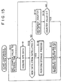
- Fig. 15 is a flowchart of steps detailing the
process in step S78 of Fig. 13;
- Fig. 16 is a timing chart in effect when the GPS
device is activated continuously;
- Fig. 17 is a timing chart in effect when the GPS
device is activated intermittently;
- Fig. 18 is a timing chart showing how the GPS
device works when the mark button is operated;
- Fig. 19 is a flowchart of steps performed by the
GPS device connected to the personal computer;
- Fig. 20 is a flowchart of steps detailing the
process in step S136 of Fig. 19;
- Fig. 21 is a flowchart of steps detailing the
process in step S158 of Fig. 20;
- Fig. 22 is a flowchart of steps detailing the
process in step S175 of Fig. 21;
- Fig. 23 is a schematic view of a typical screen
appearing on a display 19;
- Fig. 24 is a schematic view of a typical screen
that appears when an interval setting field is operated;
- Fig. 25 is a schematic view of a typical error
message generated in case of an error during data
exchanges between the personal computer and the GPS
device;
- Fig. 26 is a schematic view of a data transfer
indication window that appears during data exchanges
between the personal computer and the GPS device;
- Fig. 27 is an explanatory view of a typical image
file structure;
- Fig. 28 is a flowchart of steps performed by the
personal computer 4 when specifying positions where image
data were acquired;
- Fig. 29 is an explanatory view of log data;
- Fig. 30 is an explanatory view showing how an image
capture position is illustratively estimated; and
- Fig. 31 is an explanatory view of storage media for
use with the invention.
-
DETAILED DESCRIPTION OF THE PREFERRED EMBODIMENTS
-
Fig. 1 is a schematic view outlining a typical
configuration of an information processing system
embodying the invention. A GPS device 1 receives signals
from satellites, not shown, analyzes the received signals
to compute positions of reception (latitude and
longitude), and stores the computed position information.
Satellites usually carry an atomic clock each so that the
GPS device 1 may acquire time information from the signal
received therefrom. The time information thus obtained is
also stored. In the description that follows, the
information comprising position and time information
stored in the GPS device 1 will be referred to as log
data. A digital camera 2 captures images of subjects, and
stores data constituting the captured images onto a
storage medium such as a floppy disk 3 (the images
captured by the digital camera 2 are hereunder assumed to
be stored on the floppy disk 3).
-
Besides the floppy disk 3, other storage media such
as a portable semiconductor memory 5 may be used to
accommodate the images taken by the digital camera 2. If
the digital camera is equipped with a communication
function, the captured image data may be transmitted
through the function to another device for storage
therein.
-
A personal computer 4 is connected to the GPS
device 1 through a USB (Universal Serial Bus) cable and
is fed with log data from inside the GPS device 1. The
personal computer 4 may also be connected to the digital
camera 2 through a USB cable. Thus connected, the
personal computer 4 may read image data from the digital
camera 2. It is also possible for the personal computer 4
to retrieve image data from the floppy disk 3.
-
Fig. 2 is a block diagram showing an internal
structure of the personal computer 4. A CPU 11 of the
personal computer 4 carries out various processes in
accordance with programs held in a ROM (read only memory)
12. A RAM (random access memory) 13 accommodates data and
programs that may be needed by the CPU 11 during process
execution. An input/output interface (I/F) 14 is
connected with a keyboard 15 and a mouse 16, sending
signals from these components to the CPU 11. The I/O
interface 14 is also connected with a floppy disk drive
(FDD) 17 and a hard disk drive (HDD) 18 so that data and
programs are written and read thereto and therefrom. The
I/O interface 14 is further connected with a display 19
as well as with the GPS device 1 via a USB port 20. An
internal bus 21 interconnects these components.
-
Figs. 3A through 3D are schematic views sketching
an appearance of the GPS device 1. Fig. 3A is a front
view, Fig. 3B is a back view, Fig. 3C is a right-hand-side
view, and Fig. 3D is a bottom view, of the GPS
device 1. The GPS device 1 is made up of an antenna 31
and a body 32. The antenna 31 is attached to the body 32
in a backward swiveling manner. The body 32 is furnished
with a GPS lamp 33, a REC lamp 34 and a POWER lamp 35, as
well as a mark button 36 and a power button 37. A PC hook
38 is also provided on the body 32.
-
The PC hook 38, used to attach the GPS device 1 to
a notebook type personal computer 4 (mobile computer),
moves in an extendable and retractable manner with
respect to the body 32. Although Fig. 3C shows the PC
hook 38 being extended (extracted) away from the body 32,
the PC hook 38 is usually retracted into the body 32 to
avoid interference with nearby objects. Loaded with a
spring (not shown), the PC hook 38 retracts by itself
into the body 32 when released from its manually extended
position.
-
The PC hook 38, extended from the body 32 as shown
in Fig. 3C, clips the GPS device 1 onto a notebook type
personal computer 4. More specifically, with the personal
computer 4 opened as depicted in Fig. 4, an edge of the
display 19 is sandwiched between the extended PC hook 38
and the body 32. The components attach the GPS device 1
onto the personal computer 4. Since the PC hook 38 is
loaded with the spring as mentioned, the extended hook
puts a certain amount of pressure onto the display 19
against the body 32 to prevent the GPS device 1 from
falling in case of an impact or vibrations exerted on the
computer 4.
-
When the GPS device 1 is clipped onto the personal
computer as shown in Fig. 4, they may constitute a
navigation system used illustratively on vehicles. The
personal computer 4 is made to execute an application
program that runs the navigation system. The application
program in operation causes the display 19 illustratively
to indicate a map containing the current position of the
system. Data for displaying the current position are
computed using position information acquired by the GPS
device 1. Where the personal computer 4 and GPS device 1
are used as the navigation system, the antenna 31
attached pivotally to the body 32 may be suitably
adjusted in angle relative to the body 32 before being
fixed (i.e., at an optimal angle for receiving signals
from satellites), as illustrated in Fig. 4.
-
The GPS device 1 may be carried around by a user.
In such a case, the user may retract the PS hook 38 into
the body 32 to avoid interference with nearby objects. A
strap may be threaded through a strap buckle 39 (Fig. 3B)
on the device body, and the strap may be passed around
the user's neck or hooked onto his belt for carrying
purposes. Illustratively, as sketched in Fig. 5, the user
may thread a long strap through the strap buckle 39 to
hang the GPS device 1 from his neck for portable use.
-
As shown in Fig. 3B, the GPS device 1 has a battery
lid 40 on its back. Displacing the battery lid 40
rightward as seen in Fig. 3B opens the lid. Either
primary or second batteries may be used. The GPS device 1
may be designed to have a function for letting secondary
batteries be recharged while they are being loaded in the
device 1. The GPS device 1 also has a USB port 42
allowing the device 1 to exchange data with the personal
computer 2.
-
Fig. 6 is a block diagram showing an internal
structure of the GPS device 1. As mentioned above, the
GPS device 1 is composed of the antenna 31 and the body
32. The body 32 includes circuits that carry out diverse
processes. Fig. 6 depicts blocks that functionally
categorize these circuits. An operation unit 51 includes
the mark button 36 and power button 37 manipulated by the
user to effect desired operations. A storage unit 52
stores log data.
-
A control unit 53 generates log data based on
signals received through the antenna 31, stores the log
data thus generated, and performs processes to address
signals coming through the USB port 42 or from the
operation unit 51. A power supply unit 54 supplies the
necessary components of the GPS device 1 with power
derived from batteries or from the personal computer 4
via the USB port 42. A counter unit 55 performs time
management, manages various counter values (to be
described later), and feeds the management information to
the control unit 53.
-
The GPS device 1 has three defined modes: GPS mode,
PC mode, and storage mode. The GPS mode is selected when
the GPS device 1 is connected to the personal computer 4
for use as a GPS signal receiving antenna of a navigation
system. The PC mode is selected when the GPS device 1
outputs log data from the storage unit 52 or establishes
various settings as instructed by the personal computer 4
connected to the GPS device 1. The storage mode is
selected illustratively for the GPS device 1 to be
carried around by the user with log data held in the
storage unit 52.
-
The storage mode is further classified into three
states: wake state, sleep sate, and wake-up sate. The
wake state is a state in which data are being stored. In
the sleep state, data storing operations are being halted.
The wake-up state is a state in which the GPS device 1 is
roused temporarily from its sleep state to perform a data
storing operation before going back to the sleep state.
-
The GPS device 1 has switches built inside. These
switches are operated by the control unit 53 depending on
which of the three modes above is currently selected.
More specifically, the GPS device 1 has switches 61 and
62 furnished as shown in fig. 7. In the GPS mode, the
control unit 53 connects the switch 61 to a terminal A1
and the switch 62 to a terminal B1.
-
In the PC mode, the switch 61 is connected either
to the terminal A1 or to a terminal A2 while the switch
62 is connected to a terminal B2. In the PC mode, the GPS
device 1 operates in keeping with commands from the
personal computer 4. If a command tells the GPS device 1
to act as a GPS instrument (i.e., to output signals
received by the antenna 31), then the switch 61 is
connected to the terminal A1; if a command instructs the
GPS device 1 to output log data from the storage unit 52,
then the switch 62 is connected to the terminal A2. The
switch 61 is forcibly connected (as part of
initialization) to the terminal A1 if the GPS device 1 is
judged to be currently capable of communicating (data)
with the personal computer 4; otherwise the switch 61 is
connected to the terminal A2.
-
In the storage mode, the control unit 53 connects
the switch 61 to the terminal A2. Since the GPS device 1
is disconnected from the personal computer 4 when the
storage mode is in effect, the switch 62 may be connected
either to the terminal B1 or to the terminal B2 with no
operative difference resulting from the two settings.
Thus the switch 62 is connected to the terminal B1 by
default in the storage mode.
-
How the GPS device 1 works will now be described by
referring to the flowchart of Fig. 8. The steps making up
the flowchart of Fig. 8 are performed when the GPS device
1 is not connected with the personal computer 4, i.e.,
when the storage mode is in effect. Neither the GPS mode
nor the PC mode applies to the workings here.
-
In step S1 of Fig. 8, the control unit 53 checks to
see if the power button 37 is operated. The process of
step S1 is repeated until the power button 37 is judged
to be operated (i.e., the GPS device 1 maintains its
status until the power button 37 is operated). If the
power button 37 is judged to be operated, step S2 is
reached. In step S2, a check is made to see if the wake
state is selected.
-
If in step S2 the wake state is judged to be in
effect, i.e., it the GPS device 1 is already turned on
and its power button 37 is operated with log data being
stored, then step S3 is reached. In step S3, a check is
made to see if the power button 37 is being actuated
longer than three seconds. The period of three seconds is
cited here merely as a typical reference value; other
duration in seconds may be adopted instead. The reference
value is established to serve as a criterion by which to
pick one of several possibilities: the power button 37
may have been operated to turn on or off the GPS device
1; the power button 37 may have been actuated to execute
a process of step S7 (to be described later); or the
power button 37 may have been activated inadvertently
while the device is being carried around strapped
illustratively to the user's belt (operational error).
-
If in step S3 the power button 37 is not judged to
be actuated longer than three seconds, an operational
error is recognized and no action takes place. If the
power button 37 is judged to be actuated longer than
three seconds in step S3, then step S4 is reached in
which a power-off process is carried out.
-
Fig. 9 is a flowchart of steps detailing the power-off
process in step S4. When the power-off process is
initiated, the supply of signals from the antenna 31 is
stopped in step S21. In step S22, an end flag is set to 1.
A structure of log data to be stored is explained
hereunder. One piece of log data is formed as a 19-byte
fixed-length data item, as shown in Fig. 10A. The byte
size, to be discussed below, is merely an example and may
be replaced by any other suitable byte size.
-
Of the 19 bytes making up each log data item, one
byte is assigned to flag data, 17 bytes are allocated to
a log data body, and the remaining one byte is
apportioned to status data. The flag data have a data
structure shown in Fig. 10B. In the single byte flag data,
a start flag, an end flag, a mark flag and an O/G flag
are each assigned one bit; the remaining four bits are
set aside as dummies.
-
The start flag is set to 1 when indicating the
first log data item recorded with the storage mode
brought into effect; otherwise (i.e., when the data item
in question is the second or subsequent data item
recorded with the storage mode in effect), the start flag
is set to 0. In like manner, the end flag is set to 1
when indicating the last log data recorded in the storage
mode; otherwise the end flag is set to 0.
-
The mark flag is set to 1 when indicating a logo
data item recorded by operation of the mark button 36 (to
be described later in detail); otherwise the mark flag is
set to 0.
-
If the O/G flag is set to 1 while the start flag is
at 0, that means the log data item in question is not
data stored in the current storage mode but the most
recently stored data from the previous storage mode. If
the O/G flag is set to 0 while the start flag is at 0,
that means the stored log data item is data recorded in
the current storage mode. If the O/G flag is set to 1
while the start flag is at 1 (i.e., if the flags indicate
the first log data item recorded in the current storage
mode), that means the log data are those recorded from
beginning to end in the Tokyo geodetic system. If the O/G
flag is set to 0 while the start flag is at 1, that means
the log data are those stored from beginning to end in
the World Geodetic System (WGS84).
-
The log data body is structured as shown in Fig.
10C. Of the 17 bytes constituting the data body, 6 bytes
stand for a time of day, 0.5 bytes for latitudinal and
longitudinal hemispheres, 3.5 bytes for a latitude, 4
byte for a longitude, 1.5 bytes for a velocity, and 1.5
bytes for an azimuth.
-
The time of day is defined in terms of year, month,
day, hours, minutes, and seconds based on UTC (Universal
Time Coordinated). The latitudinal and longitudinal
hemispheres are defined by the following data: if the
most significant bit is 0, that means subsequent
latitudes are in the north; it the MSB is 1, that means
subsequent latitudes are in the south; if the bit next to
the MSB is 0, that means subsequent longitudes are in the
east; if the bit next to the MSB is 1, that means
subsequent longitudes are in the west.
-
The latitude is given as seven-digit numeric data
and the longitude is indicated as eight-digit numeric
data. The velocity is given as three-digit numeric data
in increments of one Km/h. The azimuth designates the
direction in which the user is advancing and is defined
by three-digit numeric data in increments of one degree
in a clockwise 360-degree range with the true north set
for 0.
-
Returning to the flowchart of Fig. 9, the end flag
in the log data is set to 1 in step S22. In step S22, a
storage process is performed. Fig. 11 is a flowchart of
steps detailing the storage process. This process is
carried out to have the above-described log data
generated and placed into the storage unit 52 (Fig. 6).
-
In step S32 of Fig. 11, the control unit 53 checks
a writable area in the storage unit 52. Specifically, a
check is made to see it the writable area has enough
space to accommodate one log data item, i.e., a 19-byte
space in this example. If the writable area is judged to
be less than 19 bytes long, step S32 is reached in which
the REC lamp 34 is illuminated. The REC lamp 34 is
illustratively red in color and remains lit red as long
as log data cannot be stored due to a lack of the
writable area.
-
If in step S31 the writable area of the storage
unit 52 is judged to have sufficient space to accommodate
the log data, step S33 is reached. In step S33, the
above-described log data are generated and written to a
designated address in the storage unit 52. In step S34,
an address is set at which to store the next log data.
Specifically, the address value is incremented by 19.
-
With the log data thus stored, step S35 is reached
in which the REC lamp 34 is lit for 0.1 second to notify
the user of the data storage. In step S36, a check is
made to see if the writable area has fallen short of a
caution level. If the available area in the storage unit
52 is judged to have dropped below the caution level, a
process is carried out to notify the user thereof. The
default caution level is set for 10 percent of the
capacity of the storage unit 52 (i.e., space to store log
data). The caution level may be modified by the user in a
manner to be described later.
-
The storage unit 52 may illustratively have a
capacity large enough to store log data every second for
up to 7.5 hours. In that case, the capacity of the
storage unit 52 amounts to 513,000 bytes (= 19 bytes x 60
seconds x 60 minutes x 7.5 hours). If the caution level
is set for 10 percent of the capacity, the level is then
established at 51,300 bytes.
-
If in step S36 the writable area is judged to be
less than the caution level, step S37 is reached. In step
S37, the REC lamp 34 keeps blinking at intervals of 0.3
seconds, informing the user that the available area in
the storage unit 52 is being exhausted. In step S38, a
beep sound is emitted as a warning. Although the beep may
sound in any tone, in any volume and in whatever melody,
the sound emission should preferably be characterized by
different melodies and tones depending on the current
status of the GPS device 1 so that the user immediately
recognizes what is happening upon hearing the sound.
Illustratively, a continuous beep emission "bleep, bleep,
bleep, ..." may be used to warn that the capacity of the
storage unit 52 is getting exhausted.
-
Suppose that the user is given such a warning of a
shortage in the writable area of the storage unit 52 and
still fails to take action such as one to end the storage
operation or to erase unnecessary log data, thus
continuously storing log data and eventually letting the
writable capacity of the storage unit 52 be totally
exhausted. In that case, the GPS device 1 is switched off,
and the stored log data are held intact unless otherwise
specified by the user. There is no possibility of any
stored log data forcibly or inadvertently erased or made
unavailable to the user at a later date.
-
If in step S36 the writable area is judged to be
higher than the caution level, the processes of steps S37
and S38 are skipped, and the storage process is brought
to and end.
-
With the storage process terminated, step S24 (Fig.
9) is reached in which all lamps are turned off. More
specifically, the GPS lamp 33, REC lamp 34 and POWER lamp
35 are switched out of their lighted or blinking state.
In step S25, a beep sound is emitted to notify the user
that the power-off process has ended. The beep may
illustratively have a melody of "(two consecutive) bleep,
bleep."
-
Returning to the flowchart of Fig. 8, suppose that
the check in step S2 has revealed that the wake state is
not in effect. In that case, step S5 is reached in which
a check is made to see if the sleep state is selected. If
in step S5 the sleep state is judged to be selected, step
S6 is reached. In step S6, as in step S3, a check is made
to see if the power button 37 is being actuated longer
than three seconds. If in step S6 the power button 37 is
judged to be actuated longer than three seconds, step S4
is reached. Step S4 has already been discussed and will
not be described here further.
-
If in step S6 the power button 37 is not judged to
be actuated longer than three seconds, step S7 is reached
in which a wake-up process is carried out. Fig. 12 is a
flowchart of steps detailing the wake-up process.
-
In step S51 of Fig. 12, the control unit 52
performs initialization preparatory to starting log data
storage. The initialization illustratively involves
getting ready for receiving signals through the antenna
31 after leaving the sleep state in which the supply of
signals received via the antenna 31 was halted (i.e.,
supply of power to the antenna 31 was stopped).
-
In step S52, the POWER lamp 35 is lit green to
notify the user that the wake-up state is selected. The
POWER lamp 35 is illuminated (or blinks) either green or
red depending on the status of the device. Likewise the
GPS lamp 33 is lit (or blinks) either green or red
depending on the status of the device. Other colors may
be adopted for the illumination. In this example, the
colors of green and red are assumed to be used for
purpose of illustration.
-
In step S53, a beep sound is emitted to notify the
user that the wake-up state is now in effect. The beep
may illustratively have a melody of "(a single) bleep"
-
When ready to store log data, the GPS device 1
enters the wake state for along as a predetermined wake
time in which log data may be stored. The wake time is a
period of time in which the sleep state is canceled (to
continue the wake-up state). The user may set the sleep
state for a desired period of time in a process to be
described later. A default wake time period of, say, 10
minutes (600 seconds) may also be used if desired.
-
The storing of log data or other predetermined
process is carried out until the wake time thus
established elapses. Once the wake time has passed, the
sleep state is resumed. The sleep state is restored
either following the wake time or upon operation of the
power button 37 by the user.
-
In step S55, the POWER lamp 35 blinks red at
intervals of four seconds and the GPS lamp 33 is turned
off, notifying the user that the sleep state is resumed
(the POWER lamp keeps blinking at intervals of 4 seconds
as long as the sleep state is in effect). In step S56, a
single bleep sound is emitted.
-
In this manner, the sleep state may be interrupted
for as long as needed by the user to perform the log data
storage process.
-
Returning to the flowchart of Fig. 8, suppose that
in step S5 the sleep state is not judged to be in effect.
In that case, step S8 is reached in which a check is made
to see if the power button 37 is being actuated longer
than three seconds. It in step S8 the power button 37 is
not judged to be actuated longer than three seconds, the
operation is regarded as an operational error and nothing
in particular is carried out in response.
-
If in step S8 the power button 37 is judged to be
actuated longer than three seconds, step S9 is reached.
Since the wake state is negated in step S2 and the sleep
state is denied in step S5, the GPS device 1 is deemed to
be in a switched-off state. In that state, the user's
obviously intentional operation of the power button 37 is
interpreted as his or her desire to turn the device on.
Thus a power-on process is carried out in step S9.
-
Fig. 13 is a flowchart of steps detailing the
power-on process. In step S71 of Fig. 13, the control
unit 53, given a signal from the operation unit 51,
judges that the power button 37 has been operated and
performs initialization accordingly for power-up. In step
S72, the POWER button 37 is lit green.
-
In step S73, the start flag is set to 1 and the O/G
flag is set to 1 or 0. As discussed above, the O/G flag
is set to 1 if the Tokyo geodetic system is in effect
with the start flag at 1; the O/G flag is set to 0 if the
WGS84 is in effect with the start flag at 1. When the
flags are thus set, step S74 is reached in which a
storage process is performed. The storage process was
already discussed in reference to the flowchart of Fig.
11 and thus will not be described further.
-
In step S75, a single bleep sound is emitted to
notify the user that the GPS device 1 is now switched on.
In step S76, a check is made to see if the sleep time is
set to zero. The sleep time is a designated period of
time in which the sleep state is allowed to continue
after the most recent storage of log data. In other words,
the sleep time is a parameter that specifies when to
store log data.
-
If the sleep time is set to zero, that means the
wake state is allow to continue in the absence of the
sleep state. If the sleep time is set to a value other
than zero, then the sleep state is to continue for as
long as the period of time defined by the value, to be
replaced later by the wake state. In other words, the
sleep state and the wake state are alternated so that log
data are stored intermittently (i.e., only in each wake
state). The wake state may continue for up to a period
defined as a maximum wake time.
-
The sleep time and the wake time may be defined by
the user as desired. By default, the sleep time is set
illustratively to two minutes (120 seconds) and the wake
time to 10 minutes (600 seconds).
-
If in step S76 the sleep time is judged to be other
than zero, step S77 is reached in which an intermittent
operation process is performed. Fig. 14 is a flowchart of
steps detailing the intermittent operation process. In
step S91 of Fig. 14, the counter unit 55 (Fig. 6) on
which to count the wake time is set to the currently
established wake time.
-
In step S92, GPS data are acquired, generally at
intervals of one second. If the GPS data are derived from
signals currently received from satellites, the data are
used as new data. If no signal can be received from
satellites for the movement, the most recently acquired
data from satellites are utilized as old data. In step
S93, a check is thus made to see if the GPS data obtained
in step S92 are new data (based on signals from
satellites).
-
If in step S93 the GPS data are not judged to be
new data, step S94 is reached. In step S94, the value on
the counter unit 55 is decremented by one (i.e., by 1
second). In step S95, a check is made to see if the
counter value has reached zero. In other words, it is
determined whether the wake time has expired. If in step
S95 the counter value is not judged to be zero, step S92
is reached again and subsequent steps are repeated. If in
step S95 the counter value is judged to be zero, step S97
is reached.
-
If in step S93 the GPS data are judged to be new
data, step S96 is reached for a storage process. The
storage process has already been discussed and thus will
not be described here further. With the storage process
completed, step S97 is reached in which the control unit
stands by in a sleep state that may last for as long as a
predetermined sleep time. Specifically, in intermittent
operation, the storage process is carried out the moment
GPS data are obtained from signals coming from satellites
after the wake state has been brought into effect. Once
the storage process is performed, the sleep state is
resumed immediately. Power dissipation is minimized
because the sleep state is restored immediately after new
GPS data are acquired.
-
If the predetermined sleep time for the sleep state
is two minutes, if the predetermined wake time for the
wake state is one minute, and if the GPS device is
indoors or otherwise located not to be able to receive
signals from satellites, then log data are stored every
three minutes. If the GPS device is outdoors or otherwise
located to be able to receive signals from satellites
easily and if log data are stored one second after the
wake state is selected, then the log data are stored
approximately every two minutes thereafter.
-
If no signal is received from satellites in the
wake state (i.e., if no new data are obtained), then the
process of step S96 is never carried out. In that case,
no log data are stored.
-
If in step S97 the predetermined sleep time has
expired in the sleep state, step S91 is reached again.
The wake state is then selected again and subsequent
steps are repeated.
-
The steps above constituting the flowchart of Fig.
14 are carried out as an interruption when the power
button 37 is operated, when the writable area in the
storage unit 52 has been exhausted, or when the supply of
power from the power supply unit 54 (with batteries) is
stopped. Suitable processes are performed depending on
what has actually taken place.
-
Returning to the flowchart of Fig. 13, suppose that
in step S76 the sleep time is judged to be zero. In that
case, step S78 is reached in which a continuous operation
process is carried out. Fig. 15 is a flowchart of steps
detailing the continuous operation process. In step S111
of Fig. 15, the counter on which to count an interval
time is set to a predetermined interval time. The
interval time is used to designate the recording density
of log data and may be set to a period between one second
and one hour. The default interval time is illustratively
five seconds, which means log data are stored at
intervals of five seconds.
-
The processes in steps S112 through S116 are the
same as those in steps S92 through S96 of Fig. 14 and
thus will not be described further. After the storage
process of step S116 is completed, step S117 is reached
in which the control unit stands by for a period defined
by the remaining counter value (a state in which log data
storage or other process is not performed).
Illustratively, if the interval time is set for five
seconds, the control unit stands by for five seconds,
then stores log data, then stands by for another five
seconds, and so on. When the standby state in step S117
ends, step S111 is reached again, and subsequent steps
are repeated.
-
Log data are recorded only when signals can be
received from satellites. If no signals are received from
satellites, no log data are recorded and the standby
state is selected. If the interval time is set for longer
than one minute, the standby state is replaced by the
sleep mode. This makes it possible to minimize power
dissipation in the continuous operation process as in the
case of the intermittent operation process.
-
As with the intermittent operation process, the
above steps constituting the flowchart of Fig. 15 are
carried out as an interruption when the power button 37
is operated, when the writable area in the storage unit
52 has been exhausted, or when the supply of power is
stopped.
-
Below is a description of what takes place when the
mark button 36 is operated. In the storage mode with the
wake state or wake-up sate in effect, operating the mark
button 36 carries out a specific process. In the wake or
wake-up state, GPS data may or may not be acquired (i.e.,
signals from satellites may or may not be received by the
antenna 31).
-
If the mark button 36 is operated while GPS data
are being acquired, position and time information in
effect at the time of the button operation is stored as
log data. In that case, any interval time set for the
storage mode is disregarded. That is, log data are stored
the moment the mark button 36 is operated; there is no
specific timing for log data to be stored. The same holds
when the current GPS data cannot be acquired. With no GPS
data received from satellites, however, it is impossible
to store (or generate) log data including position
information based on the new GPS data. In such a case,
log data are generated in a manner including the most
recent position information (old data) based on signals
from satellites.
-
Time information is supplied by the counter unit 55.
In managing its own time, the counter unit 55 corrects
the time on the basis of signals received from satellites.
If the mark button 36 is operated with no signals
acquired from satellites, the counter unit 55 supplies
the self-managed time information to the control unit 53.
In turn, the control unit 53 generates log data that
include the supplied time information, and stores the
generated log data into the storage unit 52.
-
As described, data to be stored by operation of the
mark button 36 are accompanied by a mark flag (set to 1)
when actually recorded. If the log data contain old data,
they are stored with the O/G flag set to 1.
-
The storing of log data outlined above is described
below in more detail with reference to timing charts in
Figs. 16 through 18. Fig. 16 is a timing chart in effect
when log data are stored in the continuous operation
process in the storage mode. The GPS device 1 is switched
on by operation of the power button 37 at a given point
in time. This sets the start flag to 1 and initiates log
data storage. In the continuous operation process, log
data are stored at intervals of a predetermined interval
time.
-
In Fig. 16, the time interval is thus the same
between P0 and P1, between P1 and P2, ..., and between P5
and P6. The GPS lamp 33 is lit green when signals from
satellites are normally received, and glows red if the
signals are not received normally. As long as the
satellite signals are normally received at each
predetermined interval time (with the GPS lamp 33 lit
green), log data are stored (at P0, P1, P3, P5, P6). If
the signals are not normally received (with the GPS lamp
33 glowing red), no log data are stored (at P2, P4).
-
When log data are normally stored, the REC lamp 34
is lit red. If no log data are recorded, the REC lamp 34
is not illuminated. If the power button 37 is operated to
designate removal of power during log data storage, log
data with an end flag are stored and the log data storage
process comes to and end. The POWER lamp 35 keeps glowing
green from the time the start flag is stored until the
end flag is set.
-
The storing of log data by the intermittent
operation process in the storage mode will now be
described with reference to the timing chart of Fig. 17.
As in the case of the continuous operation process, a
start flag is set upon power-up and an end flag is set at
power-off in correspondence with the log data stored
concurrently. The GPS lamp 33 is lit green when the
satellite signals are normally received and glows red
when the signals are not normally received. During the
intermittent operation process, the wake state (with the
POWER lamp 35 lit green) and the sleep state (with the
POWER lamp 35 blinking red) are alternated. In the wake
state, the GPS lamp 33 glows either green or red
depending on the status of signal reception as described
above. In the sleep sate, the GPS lamp 33 is turned off.
-
If signals are normally received from satellites in
the wake state, log data are stored (at P0, P1, P3). If
the satellite signals are not normally received in the
wake state (i.e., while the wake time elapses), no log
data are stored (at P2). As soon as log data are stored,
the sleep state is selected. The immediate resumption of
the sleep state is designed to minimize battery power
dissipation during the intermittent operation process.
-
Described below with reference to the timing chart
of Fig. 18 is the storing of log data by operation of the
mark button 36 during the intermittent operation process
in the storage mode. Before operating the mark button 36,
the user needs to check the status of the GPS device 1.
More specifically, the user must check whether the GPS
device 1 is switched on and, if the device is found
active, must check whether the wake state or the sleep
state is in effect.
-
The checks above may be carried out by viewing the
POWER lamp 35. If the POWER lamp 35 is not lit, the user
knows that power is still off. In that case, the power
button 37 is operated to switch on the GPS device 1. If
the POWER lamp 35 is seen blinking red at intervals of
four seconds, the user recognizes the sleep state. The
power button 37 is then actuated (for less than three
seconds) to bring the GPS device 1 into the wake-up state.
-
Figs. 18 depicts the state transitions outlined
above. The user's operation of the power button 37 in the
sleep state brings about the wake-up state. In the wake-up
state, the GPS lamp 33 starts glowing green if
satellite signals are being received and is lit red if
the signals are not received, as described. The user
checks that the GPS lamp 33 is lit green, before
operating the mark button 36. The mark button 36 is
operated by the user with his or her express intention to
store position information in effect at a particular
point in time. Thus the mark button 36 is operated in
principle while the GPS lamp 33 is being lit green.
-
Operating the mark button 37 stores the position
information at that point in time. The timing chart of
Fig. 18 indicates illustratively that the mark button 36
is operated while the GPS lamp 33 is glowing green. It is
presumed, however, that the user can also operate the
mark button 36 while the GPS lamp 33 is glowing red.
-
In the latter case, the user presumably operates
the mark button 36 in order to mark (i.e., store) at
least the current time while being aware that position
information is not obtainable because the GPS lamp 33 is
glowing red. In that case, log data are stored which
include, as position information applicable to the most
recent log data, the time information managed by the
counter unit 55 and supplemented by the old flag (with
the O/G flag set to 1). Thus the position information is
not made up of the data in effect just when the mark
button 36 was operated, whereas the time information is
constituted by the current time supplied by the counter
unit 55.
-
As described, when certain information is stored by
operation of the mark button 36, that information is
recorded together with the mark flag (set to 1).
-
When the storing of log data storage is terminated
by operation of the mark button 36, the wake-up state
remains in effect until the predetermined wake time
expires or until the user operates the power button 37.
In the example of Fig. 18, the user operated the power
button 37 before the wake time expired.
-
The GPS device 1 is powered by batteries (located
under the battery lid 40) while the above-described log
data storing operation is being performed (i.e., when the
GPS device 1 is operating alone). The batteries are
exhausted progressively and drop eventually to a level
too low to sustain log data storage or other operation.
Prior to that eventuality, the user must be warned of the
reduced battery level.
-
The control unit 53 (Fig. 6) keeps watching the
battery level. If the remaining battery time is judged to
have dropped below a predetermined level (e.g., 10
percent of the fully charged state), the control unit 53
sounds a continuous beep sound (bleep, bleep, bleep, ...)
and causes the POWER lamp 35 to blink red at intervals of
0.3 seconds. The blinking continues until the batteries
are totally exhausted or until the user turns off power.
The user may establish a desired threshold battery level
as a criterion below which the exhausted-battery warning
is issued.
-
The log data thus stored into the storage unit 52
are sent to the personal computer 4 through the USB port
42. Where the personal computer 4 is connected with the
GPS device 1 by means of a USB cable, the GPS device 1 is
powered by the personal computer 4. How the GPS device 1
works when connected to the personal computer 4 through
the USB will now be described by referring to a flowchart
in Fig. 19.
-
In step S131 of Fig. 19, the control unit 53 checks
to see if a USB cable (not shown) is connected to the USB
port 42. Step S131 is repeated until the USB cable is
judged connected to the USB port 42. When thus connected,
the personal computer 4 powers the GPS device 1. In order
to minimize power dissipation of the personal computer 4,
the computer is arranged to power the GPS device 1 only
when the latter needs to be powered. Thus in step S132, a
check is made to see if an application program requiring
data from the GPS device 1 has been started up on the
personal computer 4.
-
If in step S132 the relevant application program is
not judged to be activated, step S133 is reached. In step
S133, a check is made to see if the wake state is
selected (including a wake state brought about while the
wake-up state is in effect). If in step S133 the wake
state is judged to be selected, step S135 is reached. If
the wake state is not judged to be in effect in step S133,
step S134 is reached.
-
In step S134, a check is made to see if the GPS
device 1 is in the sleep state. If in step S134 the sleep
state is judged to be in effect, step S135 is reached.
Control is passed on to step S135 in one of two ways:
when the wake state was judged to be selected in step
S133, or when the sleep state was judged to be in effect
in step S134. This is a stage where the GPS device 1 is
being switched on.
-
When the user connects the GPS device 1 to the
personal computer 4, it is presumed that the GPS device 1
is to be utilized in the GPS mode or in the PC mode. This
necessitates terminating the wake state or sleep state
that is a state for data storage. Thus a power-off
process is carried out in step S135. The power-off
process has already been discussed and will not be
described here further.
-
If in step S134 the sleep state is not judged to be
in effect, i.e., if the GPS device 1 is judged turned off,
then the processing of Fig. 19 comes to and end.
-
If in step S132 the relevant application program is
judged to be active on the personal computer 4, step S136
is reached for a GPS mode process. Fig. 20 is a flowchart
of steps detailing the GPS process.
-
In step S151 of Fig. 20, the GPS device 1 is
initialized preparatory to starting the GPS mode process.
The initialization illustratively involves suitably
setting the switches 61 and 62 (Fig. 7) and making
arrangements to receive the supply of power from the
personal computer 4. In step S152, GPS data start getting
acquired. In step S153, the switches 61 and 62 are
operated so as to output signal information received via
the antenna 31 to the personal computer 4 through the USB
port 42.
-
In step S154, a check is made to see if any data
are input from the personal computer 4. Basically, the
GPS device 1 in the GPS mode only supplies position and
time information to the personal computer 4 and receives
no data therefrom. If in step S154 any data are judged to
be output by the personal computer 4 to the GPS device 1,
that means the user wants to operate the GPS device 1 by
means of the personal computer 4. In other words, the
user's desire to switch to the PC mode is recognized.
Thus if any data from the personal computer 4 are
detected in step S154, step S155 is reached.
-
In step S155, a check is made to see if the data
from the personal computer 4 specify a switchover to the
PC mode. If in step S155 the data from the personal
computer 4 are not judged to be something designating a
switchover to the PC mode, then the data are regarded as
irrelevant to the GPS device 1 and step S156 is reached.
Step S156 is also reached when no data are judged to be
admitted from the personal computer 4.
-
In step S156, a check is made to see if the
relevant application program has been activated. If
control has been passed on to the GPS mode process
outlined in Fig. 20 (i.e., process of step S136 in Fig.
19), that means the application program utilizing the GPS
device 1 as a GPS antenna has been started up. The check
in step S156 is intended to keep constantly watching
whether the relevant application program is active.
-
In judging that the relevant application program is
off, the above check in step S156 allows the GPS device 1
to be turned off to minimize power dissipation since the
GPS device is currently not needed. Turning off the GPS
device 1 cuts off the supply of the currently unnecessary
power from the personal computer 4, which translates into
savings of power resources in the computer 4.
-
Thus if the relevant application program is judged
to be inactive in step S156, step S157 is reached in
which the GPS device 1 is switched off. If in step S156
the application program is judged to be on, step S152 is
reached again and subsequent steps are repeated (i.e.,
the GPS mode is maintained).
-
If in step S155 the input data are judged to be
those specifying a switchover to the PC mode, step S158
is reached in which a PC mode process is performed. Fig.
21 is a flowchart of steps detailing the PC mode process.
In step S171 of Fig. 21, a check is made to see if any
data are input from the personal computer 4. If in step
S171 no data are judged to come from the personal
computer 4, step S172 is reached.
-
In step S172, a check is made to see if the
application program relevant to the GPS device 1 has been
started up on the personal computer 4. This process is
the same as that in step S156 of Fig. 20 and thus will
not be discussed further. Whatever mode is currently in
effect, constant checks are made on whether or not the
application program relevant to the GPS device 1 is
active so as to minimize power dissipation both in the
personal computer 4 and in the GPS device 1.
-
If in step S172 the relevant application program is
judged to be on, step S171 is reached again and
subsequent steps are repeated (i.e., the PC mode is
maintained). If the relevant application program is
judged to be off in step S172, step S157 (of Fig. 20) is
reached and the GPS device 1 is switched off.
-
If in step S171 any data are judged to be input
from the personal computer 4, a check is made to see if
the input data constitute a command designating a
switchover to the GPS mode. If in step S171 the data are
judged to be the command specifying transition to the GPS
mode, step S174 is reached for a GPS mode process. The
GPS mode process is constituted by the steps making the
flowchart in Fig. 20. Thus from step S174, control is
returned to step S151 (of Fig. 20) and subsequent steps
are repeated.
-
If in step S173 the input data are not judged to
constitute a command designating a switchover to the GPS
mode, step S175 is reached for a command analysis and
execution process in which the command from the personal
computer 4 is analyzed and the operation specified
thereby is carried out. Fig. 22 is a flowchart of steps
detailing the process of analyzing and executing the
command from the personal computer 4.
-
In step S201 of Fig. 22, a check is made to see if
the command is a reset command. If the command is judged
to be a reset command, step S202 is reached for a reset
process. As described above, the GPS device 1 has a
plurality of parameters such as those defining the sleep
time and wake time. These parameters may be set as
desired by the user. The reset process, when carried out,
resets the user-defined parameters to the default
parameter values.
-
If in step S201 the command is not judged to be the
reset command, step S203 is reached. In step S203, a
check is made to see if the command is a USB power
command. If in step S203 the command is judged to be one
related to the supply of power through the USB, step S204
is reached. In step S204, the supply of power through the
USB is turned on or off as designated by the command.
-
If in step S203 the command is not judged to be the
USB power command, step S205 is reached. In step S205, a
check is made to see if the command is an antenna power
command. If in step S205 the command is judged to be one
related to the supply of power to the antenna 31, step
S206 is reached. In step S206, the supply of power to the
antenna 31 is turned on or off as specified by the
command.
-
If in step S205 the command is not judged to be the
antenna power command, step S207 is reached. In step S207,
a check is made to see if the command is an ID output
command. If in step S207 the command is judged to be one
designating the output of a device ID, step S208 is
reached in which an ID code unique to the GPS device 1 in
question is output.
-
If in step S207 the command is not judged to be the
ID output command, step S209 is reached. In step S209, a
check is made to see if the command is a storage dump
command. If in step S209 the command is judged to be one
designating a dump of the storage unit 52, step S210 is
reached in which a dump process is started. The dump may
be halted halfway. Thus if in step S209 the command is
not judged to be the storage dump command, step S211 is
reached in which a check is made to see if the command is
a dump halt command.
-
If in step S211 the command is judged to be the
dump halt command, step S212 is reached for a dump halt
process. If in step S211 the command is not judged to be
the dump halt command, step S213 is reached. In step S213,
a check is made to see if the command is a read command.
If in step S213 the command is judged to be one
designating a read operation from the storage unit 52,
step S214 is reached. In step S214, the data designated
by the command are read from the storage unit 52.
-
If in step S213 the command is not judged to be the
read command, step S215 is reached. In step S215, a check
is made to see if the command is a write command. If in
step S215 the command is judged to be one designating the
writing of data to the storing unit 52, step S216 is
reached. In step S216, the data designated by the command
are written to the storage unit 52.
-
The command analysis outlined in Fig. 22 is only an
example and may be replaced by variations embracing other
commands provided to execute varieties of processes. The
flowchart in Fig. 22 thus describes in an illustrative
fashion how any of such commands from the personal
computer 4 is typically analyzed and how a relevant
process is carried out in accordance with the result of
the analysis.
-
The processing of Fig. 22 is performed every time a
command is input. At the end of the processing in Fig. 22,
step S171 of Fig. 21 is reached again and subsequent
steps are repeated. Upon completion of the processing in
Fig. 21, step S157 of Fig. 20 is reached and the GPS
device 1 is switched off. When the processing of Fig. 20
is terminated, the processing of Fig. 19 is also brought
to an end. When the GPS device 1 is connected to the
personal computer 4 through the USB, the steps in Figs.
19 through 22 are carried out as described above.
-
In order to output a desired command illustratively
in the manner outlined in Fig. 22, the user is required
to perform necessary operations on a screen of the
display 19 of the personal computer 4. Fig. 23 shows a
typical screen on which such operations are carried out.
-
On the display 19, a setting window 71 appears on
which to operate (i.e., set) parameters for determining
the way the GPS device 1 should operate. The setting
window 71 is made up of three major portions: an
operation setting area 72, a memory setting area 73, and
a battery setting area 74. The operation setting area 72
comprises an interval setting field 75 in which to set a
log storage interval, and an effective time setting field
76 in which to set an effective wake-up time.
-
The memory setting area 73 is constituted by an
alarm setting field and a clear button 77. The alarm
setting field allows the user to set a threshold
percentage of the remaining memory capacity (of the
storage unit 52) as a criterion below which an alarm is
issued. The clear button 77 is operated to clear all
stored log data. As described earlier, log data keep
being written to the storage unit 52 unless erased
intentionally by the user. To ensure a sufficient
writable capacity, the user should operate the clear
button 77 periodically to clear the storage unit 52.
-
The battery setting area 74 constitutes a field in
which to set a threshold percentage of the remaining
battery charges as a criterion below which an alarm is
issued. Under the battery setting area 74 are three
buttons: a reset-to-default button 78-1, an OK button 78-2,
and a cancel button 78-3. The reset-to-default button
78-1 is operated to reset the user-established parameters
to the default values. The OK button 78-2 is operated to
confirm the end of the parameter setting. The cancel
button 78-3 is operated to cancel any parameters that
have been set so far but are considered unnecessary, or
to close the setting window 71.
-
In setting parameters in various areas or fields,
the user points a cursor where desired on the screen by
operating the mouse 16 (Fig. 2) or a similar pointing
device and by clicking on or otherwise manipulating the
device. For example, the user may point a cursor 79 to
the interval setting field 75 by operating and clicking
on the mouse 16. This causes a pull-down menu 81 to
appear as shown in Fig. 24. The menu 81 indicates values
that may be used as an interval for log storage. A scroll
bar appears on the right-hand side of the pull-down menu
81, allowing the user to display the bidden values when
operated.
-
Illustratively, the log storage interval may be set
for any one of 1 second, 3 seconds, 5 seconds, 10 seconds,
30 seconds, 1 minute, 3 minutes, 5 minutes, 10 minutes,
30 minutes, and 60 minutes (1 hour). The pull-down menu
81 may be arranged to contain a field in which any other
time period may be set as desired. In setting the
interval, the user should take into account the
circumstances under which log data are to be stored. For
example, if log data are expected to be recorded during
walking, the moving speed is not very high so that a
relatively long interval of, say, 10 or 30 minutes may be
selected. If log data are expected to be stored during a
trip by car, the moving speed is high and thus a
relatively short period of, say, 30 seconds or 1 minute
should be selected to keep frequent logs.
-
Other parameters may also be set in like manner.
Obviously, arrangements may be made not merely to pick
one of the values contained in the pull-down menu 81 but
to point the cursor 81 to the field in question so that
the currently displayed value may be directly changed as
desired.
-
Every time the OK button 78-2 is operated, the data
denoting the established parameter(s) are output from the
personal computer 4 to the GPS device 1. In such a case,
the GPS device 1 receives a write command requiring the
old parameter value(s) to be replaced by the newly
established parameter(s). More specifically, in step S215
of Fig. 22, the received command is judged to be one
designating a write operation to the storage unit 52.
Step S215 is followed by step S216 in which the parameter
value(s) is written to the storage device accordingly.
-
In case an error occurs for some reason during data
exchanges between the personal computer 4 and the GPS
device 1, an error message such as is shown in Fig. 25
appears on the display 19.
-
The setting window 71 is not limited in design to
what is shown in Fig. 23; any other design may be adopted
instead. A plurality of setting windows are provided in
which to operate and set up the GPS device 1. Although
not shown, there is provided a window by which to dump
log data from the storage unit 52 of the GPS device 1 to
the HDD 18 (Fig. 2) of the personal computer 4. If that
dump window is opened and operated by the user for a dump,
a data transfer indication window such as one in Fig. 26
appears on the display 19 to indicate the data transfer
status.
-
If the user operates the cancel button in the
window of Fig. 26, the GPS device 1 interprets the action
as a dump halt command in step S211 of Fig. 22. Step S211
is followed by step S212 in which the dump process is
halted. As a result, the data transfer indication window
of Fig. 26 disappears.
-
As described, the log data including position and
time information and stored in the GPS device 1 may be
supplied to the personal computer 4. On the personal
computer 4, the user can edit, in conjunction with the
supplied log data, the image data captured by the digital
camera 2 (Fig. 1) and recorded on the floppy disk 3.
-
When recording image data, the digital camera 2
associates data making up each image with a time stamp
illustratively using a digital camera format DCF (Design
rule for Camera File) defined by the JEIDA (Japan
Electronic Industry Development Association). More
specifically, as shown in Fig. 27, an image file
accommodating an image taken by the digital camera 2 is
constituted mainly by a header and an image data body.
The header stores data about the image held in the image
data body. One of the data items making up the header is
a time of day at which the image in question was captured.
-
Described below with reference to a flowchart of
Fig. 28 is how the personal computer 4 operates in
determining the position where a specific image was taken
by the digital camera 2. In step S231 of Fig. 28, the
personal computer 4 reads log data from the GPS device 1
connected via the USB. The log data thus read out are
placed illustratively into the RAM 13 (Fig. 2). When
written to the memory, the log data are arranged in the
ascending order of chronology. Each log data item is
furnished with a counter value starting at zero. Fig. 29
depicts an example of log data placed into the personal
computer 4.
-
The log data in Fig. 29 are made up of 32 log data
items. The log data constitute a group of data items
recorded from the time the GPS device 1 was turned on
until it was switched off. In other words, a log data
group starts with a log data item whose start flag is set
to 1 and ends with a log data item whose end flag is at 1.
Of the data items constituting the log data body in Fig.
29, only those composed of a time stamp each are shown.
The times are seen here taken at intervals of 30 seconds
from 10:18:00 to 10:33:30. The log data items, numbered
with counter values 0 through 31, are arranged
chronologically on the basis of the time data held in the
log data body.
-
In step S232, the data constituting a target image
to be processed are read. The read operation is performed
as follows: from that floppy disk 3 in the FDD 17 (or
from the portable semiconductor memory 5 or a remote
source over a network) which holds image data taken by
the digital camera 2, image data having the data
structure shown in Fig. 27 are read into the RAM 13 or
onto the HDD 18. At this point, all image data may be
read from the floppy disk 3 and placed illustratively
into the RAM 13 before the data making up the target
image is retrieved from the RAM 13. Alternatively, the
image data may be read one image at a time from the
floppy disk 3.
-
In step S233, the counter value regarding the log
data to be processed is initialized to zero. In step S234,
a check is made to see if the counter value is less than
the number of all log data items plus one. In other words,
it is determined whether all log data items are subject
to the processes in step S234 and subsequent steps. In
this case, the counter value has just been set to zero
and thus it is judged to be less than the total log data
item count plus one, so that step S235 is reached.
-
In step S235, the "preceding" log data item is set
to the counter value and the "next" log data item is set
to the counter value plus one. The preceding and the next
log data items are chronologically adjacent to each other
(i.e., having consecutive counter values), the preceding
log data item being earlier by one time increment than
the next log data item. In step S236, a check is made to
see if the time of the preceding log data item was
earlier than the time at which the image was taken. In
other words, it is determined whether the time stamp of
the preceding log data item represents a time of day
previous to the time included in the target image data to
be processed read in step S232.
-
If in step S236 the time stamp of the preceding log
data item is judged to be earlier than the time of the
image capture, step S237 is reached. In step S237, a
check is made to see if the time stamp of the next log
data item is subsequent to the time of the image capture.
If in step S237 the next log item is not judged to be
subsequent to the time of the image capture, step S238 is
reached in which the counter value is incremented by one.
Regarding the log data having the newly established
counter value, the processes of step S234 and subsequent
steps are repeated.
-
If in step S237 the time stamp of the next log data
item is judged to be later than the time of the image
capture, step S239 is reached. In step S239, the position
where the image was taken is estimated. How the position
of the image capture is typically estimated is described
below with reference to Fig. 30. If the time of the image
capture is, say, "10:32:40," then the process of step
S236 judges that the log data items with counter values 0
through 28 (from "10:18:00" to "10:32:00") have time
stamps each preceding the time of the image capture. In
step S237, the next log data item is not judged to have a
time subsequent to that of the image capture. Thus steps
S234 through S238 are repeated.
-
When the counter value reaches 29 (i.e., when the
preceding log data item is associated with the time stamp
of "10:32:30" and the next log data item with "10:33:00"),
the process of step S236 judges the time of the preceding
log data item to be earlier than the time of the image
capture. In step S237, the time of the next log data item
is judged to be later than the time of the image capture.
This is the state shown in Fig. 30 in which the time of
the image capture is situated between two log data items.
-
In this example, the time of the image capture is
"10:32:40," preceded by the preceding log data item with
the time of "10:32:30" and followed by the next log data
item with the time of "10:33:00." Where the two log data
items and the time of the image capture are plotted on
the time base as sketched in Fig. 30, the point
indicating the time of the image capture is considered to
divide internally a line segment connecting the two
points representing the two log data items. If the point
denoting the time of the image capture is assumed to
divide, in proportions of 1 : 2, the distance between the
two points representing the two log data items, then the
position of the image capture can be estimated on the
basis of the position information representing the two
log data items.
-
In the example above, the position information on
the log data item with the time of "10:32:30" is
constituted by N42° 32'35'' and E135° 12'20'', whereas the
position information about the log data item having the
time of "10:33:00" is made of N42° 35'35'' and E135° 00'40''.
Because of the assumption that the position information
spanning the two positions of the log data items is
internally divided in proportions of 1 : 2, the north
latitude (N) of the position of the image capture is
estimated at N42° 33'35''. Based on the same assumption,
the east longitude (E) of the position of the image
capture is estimated at E135° 04'20''. The estimates
carried out as described above in step S239 determine the
position of the image capture corresponding to the image
capture time.
-
There may be a case in which the time of the image
capture matches the time of a given log data item, i.e.,
the case where the proportions of internal division are
0 : X (X is a value contingent on the storage interval
between log data items). In that case, the position
information about the log data item in question is
estimated to represent the position where the target
image data were acquired.
-
In terms of log data storage intervals, the GPS
device 1 works as described in one of two modes:
continuous mode in which log data are stored every second,
and intermittent mode in which log data are recorded at
intervals of up to 3,600 seconds (1 hour). Due to
obstacles, the GPS device 1 may sometimes be unable to
receive signals normally from satellites (i.e., unable to
store log data containing accurate position information).
If signals from satellites are not received in the
intermittent mode or because of obstacles, there are no
log data available containing position information
corresponding to (i.e., matching) the times of day at
which image data were acquired. Such eventualities can be
overcome by estimating the position of the image capture
in the manner described above.
-
When the image capture position is estimated (i.e.,
determined) in step S239, step S241 is reached. In step
S241, the data representing the image capture position
are associated with the target image data to be processed
before they are all written illustratively to the HDD 18.
-
Suppose that in step S234 the counter value is
judged to be larger than the total log data item count
plus one, or that in step S236 the time of the preceding
log data item is not judged to be earlier than the time
of the image capture (since comparison with the image
capture times proceeds chronologically, the judgment that
the time of the preceding log data item was not earlier
than the time of the image capture signifies that all log
data items are subsequent to the image capture time). In
such cases, step S240 is reached.
-
In step S240, it is judged that the position of the
target image data to be processed cannot be estimated. In
step S241, the image data are stored together with a data
item indicating the absence of estimates about the image
capture position.
-
In the foregoing description, two log data items
closest chronologically to the time of the image capture
were shown retrieved before estimates of an image capture
position were carried out. Alternatively, there may be
provided a step in which to search for a log data item
whose time matches an image capture time. Estimates of
the image capture position are performed only in the
absence of any matching log data item.
-
The image data thus associated with specific
positions of the image capture may be displayed as
thumbnail images at the corresponding positions on a
digital map, or may be grouped into suitable zone
categories according to the position information. Such
editing work is carried out by use of an appropriate
application program. If certain image data are displayed
on the digital map and if the position information
associated with that image has been acquired
intentionally by the user (i.e., if the position
information is derived from specific log data stored by
the user's operation of the mark button 36), then an
indication attesting to the user's choice may be
displayed as needed.
-
The log data need not be limited in their use to
being associated with image data. Alternatively, the log
data may be sorted out chronologically and plotted on a
digital map in the sorted order. The data thus plotted
provide a track traveled by the user.
-
The examples above have been shown centering on how
to deal with still pictures obtained by the digital
camera 2. However, this is not limitative of the
invention. The invention also applies to moving picture
data captured by a digital video camera or like equipment.
In practicing satellite-based position measurement, the
GPS may be replaced by the GLONASS (Global Orbiting
Navigation Satellite System).
-
The processes discussed above may be implemented
either by hardware or by software. If a series of
processes is implemented by software, programs
constituting the software are loaded from a program
storage medium into a computer having a hardware
structure dedicated to the software or into a general-purpose
personal computer capable of executing diverse
functions based on various programs that may be installed
therein.
-
The program storage medium from which to load
programs into the personal computer 4 for execution may
be any one of such media as magnetic disks 131 (including
floppy disks), optical disks 132 (including CD-ROM
(Compact Disc-Read Only Memory) and DVD (Digital
Versatile Disc)), a semiconductor memory 134 or like
package medium, and a hard disc drive constituting a ROM
112 or a storage unit 118 into which programs are stored
temporarily or permanently. Programs are stored onto the
program storage medium from wired or wireless
communication media such as local area networks, the
Internet, or digital satellite broadcast links through
such interfaces as routers and modems where necessary.
-
In this specification, the steps in which to
describe the programs offered by the program storage
medium may or may not be carried out chronologically in
the described sequence. These steps include processes
that may be executed in parallel or on an individual
basis.
-
In this specification, the term "system" refers to
a totality of multiple devices configured.
-
As described above and through the information
processing apparatus, the information processing method,
and the program storage medium according to the present
invention, time data are generated to denote times of day
at which measured position data are generated. Log data
are then generated including at least the measured
position data and the time data. With the log data placed
in storage, either the measured position data and time
data are all output, or the log data are retrieved from
storage for output. These features help enhance the
versatility or the inventive information processing
apparatus for obtaining measured position data.
-
As many apparently different embodiments of this
invention may be made without departing from the spirit
and scope thereof, it is to be understood that the
invention is not limited to the specific embodiments
thereof except as defined in the appended claims.