EP1087565A2 - Enhanced video programming system and method providing a distributed community network - Google Patents
Enhanced video programming system and method providing a distributed community network Download PDFInfo
- Publication number
- EP1087565A2 EP1087565A2 EP00308045A EP00308045A EP1087565A2 EP 1087565 A2 EP1087565 A2 EP 1087565A2 EP 00308045 A EP00308045 A EP 00308045A EP 00308045 A EP00308045 A EP 00308045A EP 1087565 A2 EP1087565 A2 EP 1087565A2
- Authority
- EP
- European Patent Office
- Prior art keywords
- packet
- content
- network
- receiving
- targets
- Prior art date
- Legal status (The legal status is an assumption and is not a legal conclusion. Google has not performed a legal analysis and makes no representation as to the accuracy of the status listed.)
- Withdrawn
Links
Images


Classifications
-
- H—ELECTRICITY
- H04—ELECTRIC COMMUNICATION TECHNIQUE
- H04L—TRANSMISSION OF DIGITAL INFORMATION, e.g. TELEGRAPHIC COMMUNICATION
- H04L12/00—Data switching networks
- H04L12/28—Data switching networks characterised by path configuration, e.g. LAN [Local Area Networks] or WAN [Wide Area Networks]
-
- H—ELECTRICITY
- H04—ELECTRIC COMMUNICATION TECHNIQUE
- H04L—TRANSMISSION OF DIGITAL INFORMATION, e.g. TELEGRAPHIC COMMUNICATION
- H04L65/00—Network arrangements, protocols or services for supporting real-time applications in data packet communication
- H04L65/10—Architectures or entities
- H04L65/102—Gateways
- H04L65/1043—Gateway controllers, e.g. media gateway control protocol [MGCP] controllers
-
- G—PHYSICS
- G06—COMPUTING; CALCULATING OR COUNTING
- G06K—GRAPHICAL DATA READING; PRESENTATION OF DATA; RECORD CARRIERS; HANDLING RECORD CARRIERS
- G06K13/00—Conveying record carriers from one station to another, e.g. from stack to punching mechanism
- G06K13/02—Conveying record carriers from one station to another, e.g. from stack to punching mechanism the record carrier having longitudinal dimension comparable with transverse dimension, e.g. punched card
- G06K13/08—Feeding or discharging cards
- G06K13/0806—Feeding or discharging cards using an arrangement for ejection of an inserted card
- G06K13/0825—Feeding or discharging cards using an arrangement for ejection of an inserted card the ejection arrangement being of the push-push kind
-
- H—ELECTRICITY
- H04—ELECTRIC COMMUNICATION TECHNIQUE
- H04L—TRANSMISSION OF DIGITAL INFORMATION, e.g. TELEGRAPHIC COMMUNICATION
- H04L65/00—Network arrangements, protocols or services for supporting real-time applications in data packet communication
- H04L65/1066—Session management
- H04L65/1101—Session protocols
-
- H—ELECTRICITY
- H04—ELECTRIC COMMUNICATION TECHNIQUE
- H04L—TRANSMISSION OF DIGITAL INFORMATION, e.g. TELEGRAPHIC COMMUNICATION
- H04L67/00—Network arrangements or protocols for supporting network services or applications
- H04L67/01—Protocols
- H04L67/10—Protocols in which an application is distributed across nodes in the network
- H04L67/1001—Protocols in which an application is distributed across nodes in the network for accessing one among a plurality of replicated servers
-
- H—ELECTRICITY
- H04—ELECTRIC COMMUNICATION TECHNIQUE
- H04L—TRANSMISSION OF DIGITAL INFORMATION, e.g. TELEGRAPHIC COMMUNICATION
- H04L67/00—Network arrangements or protocols for supporting network services or applications
- H04L67/50—Network services
- H04L67/51—Discovery or management thereof, e.g. service location protocol [SLP] or web services
-
- H—ELECTRICITY
- H04—ELECTRIC COMMUNICATION TECHNIQUE
- H04L—TRANSMISSION OF DIGITAL INFORMATION, e.g. TELEGRAPHIC COMMUNICATION
- H04L67/00—Network arrangements or protocols for supporting network services or applications
- H04L67/50—Network services
- H04L67/55—Push-based network services
-
- H—ELECTRICITY
- H04—ELECTRIC COMMUNICATION TECHNIQUE
- H04L—TRANSMISSION OF DIGITAL INFORMATION, e.g. TELEGRAPHIC COMMUNICATION
- H04L69/00—Network arrangements, protocols or services independent of the application payload and not provided for in the other groups of this subclass
- H04L69/30—Definitions, standards or architectural aspects of layered protocol stacks
- H04L69/32—Architecture of open systems interconnection [OSI] 7-layer type protocol stacks, e.g. the interfaces between the data link level and the physical level
- H04L69/322—Intralayer communication protocols among peer entities or protocol data unit [PDU] definitions
- H04L69/329—Intralayer communication protocols among peer entities or protocol data unit [PDU] definitions in the application layer [OSI layer 7]
-
- H—ELECTRICITY
- H04—ELECTRIC COMMUNICATION TECHNIQUE
- H04N—PICTORIAL COMMUNICATION, e.g. TELEVISION
- H04N21/00—Selective content distribution, e.g. interactive television or video on demand [VOD]
- H04N21/20—Servers specifically adapted for the distribution of content, e.g. VOD servers; Operations thereof
- H04N21/21—Server components or server architectures
- H04N21/222—Secondary servers, e.g. proxy server, cable television Head-end
-
- H—ELECTRICITY
- H04—ELECTRIC COMMUNICATION TECHNIQUE
- H04N—PICTORIAL COMMUNICATION, e.g. TELEVISION
- H04N21/00—Selective content distribution, e.g. interactive television or video on demand [VOD]
- H04N21/20—Servers specifically adapted for the distribution of content, e.g. VOD servers; Operations thereof
- H04N21/23—Processing of content or additional data; Elementary server operations; Server middleware
- H04N21/235—Processing of additional data, e.g. scrambling of additional data or processing content descriptors
-
- H—ELECTRICITY
- H04—ELECTRIC COMMUNICATION TECHNIQUE
- H04N—PICTORIAL COMMUNICATION, e.g. TELEVISION
- H04N21/00—Selective content distribution, e.g. interactive television or video on demand [VOD]
- H04N21/40—Client devices specifically adapted for the reception of or interaction with content, e.g. set-top-box [STB]; Operations thereof
- H04N21/43—Processing of content or additional data, e.g. demultiplexing additional data from a digital video stream; Elementary client operations, e.g. monitoring of home network or synchronising decoder's clock; Client middleware
- H04N21/4302—Content synchronisation processes, e.g. decoder synchronisation
- H04N21/4305—Synchronising client clock from received content stream, e.g. locking decoder clock with encoder clock, extraction of the PCR packets
-
- H—ELECTRICITY
- H04—ELECTRIC COMMUNICATION TECHNIQUE
- H04N—PICTORIAL COMMUNICATION, e.g. TELEVISION
- H04N21/00—Selective content distribution, e.g. interactive television or video on demand [VOD]
- H04N21/40—Client devices specifically adapted for the reception of or interaction with content, e.g. set-top-box [STB]; Operations thereof
- H04N21/43—Processing of content or additional data, e.g. demultiplexing additional data from a digital video stream; Elementary client operations, e.g. monitoring of home network or synchronising decoder's clock; Client middleware
- H04N21/435—Processing of additional data, e.g. decrypting of additional data, reconstructing software from modules extracted from the transport stream
-
- H—ELECTRICITY
- H04—ELECTRIC COMMUNICATION TECHNIQUE
- H04N—PICTORIAL COMMUNICATION, e.g. TELEVISION
- H04N21/00—Selective content distribution, e.g. interactive television or video on demand [VOD]
- H04N21/40—Client devices specifically adapted for the reception of or interaction with content, e.g. set-top-box [STB]; Operations thereof
- H04N21/45—Management operations performed by the client for facilitating the reception of or the interaction with the content or administrating data related to the end-user or to the client device itself, e.g. learning user preferences for recommending movies, resolving scheduling conflicts
- H04N21/462—Content or additional data management, e.g. creating a master electronic program guide from data received from the Internet and a Head-end, controlling the complexity of a video stream by scaling the resolution or bit-rate based on the client capabilities
- H04N21/4622—Retrieving content or additional data from different sources, e.g. from a broadcast channel and the Internet
-
- H—ELECTRICITY
- H04—ELECTRIC COMMUNICATION TECHNIQUE
- H04N—PICTORIAL COMMUNICATION, e.g. TELEVISION
- H04N21/00—Selective content distribution, e.g. interactive television or video on demand [VOD]
- H04N21/40—Client devices specifically adapted for the reception of or interaction with content, e.g. set-top-box [STB]; Operations thereof
- H04N21/47—End-user applications
- H04N21/475—End-user interface for inputting end-user data, e.g. personal identification number [PIN], preference data
- H04N21/4758—End-user interface for inputting end-user data, e.g. personal identification number [PIN], preference data for providing answers, e.g. voting
-
- H—ELECTRICITY
- H04—ELECTRIC COMMUNICATION TECHNIQUE
- H04N—PICTORIAL COMMUNICATION, e.g. TELEVISION
- H04N21/00—Selective content distribution, e.g. interactive television or video on demand [VOD]
- H04N21/40—Client devices specifically adapted for the reception of or interaction with content, e.g. set-top-box [STB]; Operations thereof
- H04N21/47—End-user applications
- H04N21/478—Supplemental services, e.g. displaying phone caller identification, shopping application
- H04N21/4782—Web browsing, e.g. WebTV
-
- H—ELECTRICITY
- H04—ELECTRIC COMMUNICATION TECHNIQUE
- H04N—PICTORIAL COMMUNICATION, e.g. TELEVISION
- H04N21/00—Selective content distribution, e.g. interactive television or video on demand [VOD]
- H04N21/40—Client devices specifically adapted for the reception of or interaction with content, e.g. set-top-box [STB]; Operations thereof
- H04N21/47—End-user applications
- H04N21/488—Data services, e.g. news ticker
- H04N21/4882—Data services, e.g. news ticker for displaying messages, e.g. warnings, reminders
-
- H—ELECTRICITY
- H04—ELECTRIC COMMUNICATION TECHNIQUE
- H04N—PICTORIAL COMMUNICATION, e.g. TELEVISION
- H04N21/00—Selective content distribution, e.g. interactive television or video on demand [VOD]
- H04N21/80—Generation or processing of content or additional data by content creator independently of the distribution process; Content per se
- H04N21/85—Assembly of content; Generation of multimedia applications
- H04N21/854—Content authoring
- H04N21/8547—Content authoring involving timestamps for synchronizing content
-
- H—ELECTRICITY
- H04—ELECTRIC COMMUNICATION TECHNIQUE
- H04N—PICTORIAL COMMUNICATION, e.g. TELEVISION
- H04N21/00—Selective content distribution, e.g. interactive television or video on demand [VOD]
- H04N21/80—Generation or processing of content or additional data by content creator independently of the distribution process; Content per se
- H04N21/85—Assembly of content; Generation of multimedia applications
- H04N21/858—Linking data to content, e.g. by linking an URL to a video object, by creating a hotspot
- H04N21/8586—Linking data to content, e.g. by linking an URL to a video object, by creating a hotspot by using a URL
Definitions
- the present invention relates to a method and apparatus for routing application layer packets of information in a network.
- Computers have the capability to provide massive amounts of educational and entertainment information by way of the Internet.
- on-line systems offer a variety of different services to users, including news feeds, electronic databases (either searchable by user directly on the on-line system, or downloadable to the user's own computer), private message services, electronic newsletters, real time games for play by several users at the same time, and job placement services, to name a few.
- currently most on-line communications occur merely through text. This is in contrast to the audio/visual presentation of the alternative electronic medium, television.
- audio/visual programs will proliferate and text will become less and less dominant in the on-line environment.
- the present invention seeks to close the gap between video programming and the vast information resources of the Internet.
- a method for routing application layer packets of information in a network comprising:
- a method of an embodiment of the invention enables dynamic reconfiguration of a network for transmitting content, such as that located using URLs.
- the network referred to as a distributed community network, preferably includes hubs which may logically reside on any machine and control the routing of packets containing content by using hubs to assist in routing packets, the burden of routing control at corresponding server is decreased, enhancing the reliability and efficiency of the network in transmitting content and permitting access to content.
- the present invention also extends to a method for routing application layer packets of information in a network, comprising:
- apparatus for routing application layer packets of information in a network comprising:
- the invention also extends to apparatus for routing application layer packets of information in a network comprising:
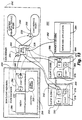
- Figure 1 illustrates an embodiment of a computer based system for receiving a video program along with embedded uniform resource locators (URLs) which direct a user's computer 16 to address locations, or web sites, on the Internet 20 to retrieve related web pages.
- the web pages correspond to the video presentation.
- the particular video programming can be delivered in analog, digital or digitally compressed formats (e.g. MPEG2) via any transmission means, including satellite, cable, wire, television broadcast or sent via the web.
- the video programming is preferably created at a centralized location, for example, as content creation 4 indicated in Figure 1, for distribution to subscribers.
- Program creation may be accomplished by any appropriate means.
- uniform resource locators URLs
- the URLs are embedded into the vertical blanking interval of the video programming by a URL encoder 8, as shown in Figure 1.
- the URLs are encoded onto eight fields of line 21 of the VBI. Line 21 is the line associated with close captioning, among other things.
- the URLs may additionally and/or alternatively be embedded in other fields of the VBI, in the horizontal portion of the video, as part of the audio channel, in any subcarrier to the video, or if the video is digital, in one of the data fields.
- the URLs may be sent down independently of the video program on a data channel.
- the URLs may be forwarded to the remote sites either prior to initiation or during the program.
- the URLs have associated time stamps which indicate to the subscriber stations when, during the video program, to display the particular web pages addressed by the URLs.
- the user can select when to call the particular web pages for display with the video program.
- line 21 is not part of the visual part of the program, and thus, is not perceptible to the human eye, thereby making it ideal to send data information to the users. Whilst the bandwidth capacity of line 21 is limited, as a system as described transmits only the URLs, and not full web pages, there is more than enough capacity. Furthermore, no additional hardware is necessary at the computer 16 to receive the video and retrieve the web pages.
- the video program may be transmitted to user sites over any transmission means, including broadcast, cable, satellite, or Internet, and may reside on video servers.
- the video program, with or without embedded URLs may be encoded onto storage means such as a video tape, for example of VHS or Beta format, or an optical disc such as CD or DVD, or any other medium.
- each receiver station comprises any Intel x86 machine (preferably a 486 processor, pentium processor, etc), an Apple Computer, UNIX or any other type of standard computer workstation.
- the local computer 16 is preferably connected to either a cable and/or broadcast television or to a local VCR or other video source.
- the local personal computer 16 preferably receives the cable transmission by cable connection on the back of the personal computer 16.
- the video/audio program may be processed for display on the computer screen using a PC card capable of displaying video signals on a computer monitor in an appropriate TV format such as PAL or NTSC.
- a PC card is a WinTV card.
- the Internet 20 connection created concurrently with the cable connection.
- the Internet 20 connection may be via high-speed line, RF, conventional modem or by way of two-way cable carrying the video programming.
- the local PC 16 has Internet access via, for example, an ASCII software mechanism.
- an associated local URL decoder 12 extracts the URLs, preferably embedded in the vertical blanking interval, with the use of a suitable VBI decoder device.
- the URL decoder 12 may be either a stand-alone unit or a card which is implemented into the personal computer 16.
- the uniform resource locators are encoded into the video as described above.
- the URLs are preferably encoded onto eight fields of line 21 of the VBI, but may also be sent independently of the video.
- a URL decoder 24 is located at the server site rather than at the subscriber location. When the decoder 24 receives the video program signal, it strips out the URL codes on line 21 of the VBI and delivers these codes independently to an Internet server 28. The URL code is then subsequently delivered over the Internet 20 to the user PC 16. Simultaneously, the video is broadcast over conventional broadcast or cable transmission means 36 to the user's personal computer 16.
- the system runs an online service over the Internet 20.
- This service is in the form of an Internet web site 62 which provides a user-interface to a database 78 and to one or more associated data servers 90.
- the service provides member accounts to TV broadcasters 66 who sign up to use the illustrated system in conjunction with their broadcasts.
- Each member broadcaster will enter the service at their computer 70 through web browser software 74 using their member account by entering various identification and password information.
- the member Once within their account, the member will be provided with a graphical user interface for pre-scheduling URLs for transmission to users 118 over a direct Internet connection 94 at particular times of day.
- the same user interface, or a variation of it, can be used by broadcasters for live transmission 82 of URLs to users at the same time as a broadcast 86.
- this interface might be a scheduling calendar (daily, weekly, monthly, yearly) in which the broadcaster 66 may allocate time periods which coincide with their broadcasts 86, and during which they will send out URLs to their users to link to web pages. For each time period (for example, a particular hour long period during the day) determined by the broadcaster 66 to be a broadcast period (a period during which they want to transmit URLs that correspond to a television show being broadcast from their TV broadcast facility 110 to the external TV 114 of the user 118 at that time), the broadcaster 66 may then enter a series of URLs into an associated file ("Link File”) for transmission over the Internet 20 at that time.
- a scheduling calendar daily, weekly, monthly, yearly
- the broadcaster 66 may allocate time periods which coincide with their broadcasts 86, and during which they will send out URLs to their users to link to web pages. For each time period (for example, a particular hour long period during the day) determined by the broadcaster 66 to be a broadcast period (a period during which they want to transmit
- This Link File may have a user interface such as a spreadsheet, table, or list, or it may be simply a tab-delimited or paragraph-delimited text-file.
- each of the records in the Link File consists of a data structure which may contain information such as: ( ⁇ timecode>, ⁇ URL>, ⁇ label or title>, ⁇ additional information>, ⁇ additional information>, etc
- the above data structure is just one example.
- the records in the Link File preferably specify the time, Internet address (i.e. URL), label (such as an associated name), and some optional additional information, for each web page the broadcaster 66 desires to launch during a show.
- each broadcaster 66 modifies their calendar and/or the Link File associated with any given time period(s) in their calendar, this information is saved into the database 78 which is attached to the site 62.
- Each broadcaster 66 may maintain multiple calendars in the database 78 if they broadcast in different time zones, for example.
- the database 78 provides the Link File records for upcoming time periods to a server 90, which may be one server or a distributed network of server programs on multiple computers across the network, to be utilized for scaling to large national or global audiences.
- the server 90 provides the Link File records, including the URLs, to the user's personal computer 16, which is connected via a network. Examples of possible networks include the public Internet 94, a direct private network, or even a wireless network.
- one or more broadcasters 66 may utilize the same schedule in the database 78 for their own broadcasts 86 or during the same broadcast.
- a network broadcaster may develop a master schedule and various affiliate broadcasters may subscribe to that schedule or copy it (in the database) and add or delete specific URLs in the schedule for their local audiences or unique programming.
- This scheme enables affiliates to insert URLs for local advertisers or local subjects into a sequence of more general URLs provided by their network broadcaster 66.
- the affiliate can add links that ride on the network feed and then redistribute it to their local audiences.
- the system of Figure 4 also enables personalization in the form of unique series of URLs specific to each user's unique profile, which are directly sent over the Internet 20 to each user's specific client software 106. This can be achieved from the broadcaster 66 to each individual user 118, or to particular collections of users. To accomplish personalization, the service may send a different stream of URLs to each user's client software program 106.
- the stream of URLs sent depends upon a user profile stored in the database 78 or the client software program 106, a user profile which is built on demand or over time for each user 118 based on criteria such as the location of the user, choices the user makes while using a client software program 106, choices the broadcaster 66 makes during a broadcast 86, or automatic choices made by an algorithm (such as a filter) residing on the service 62.
- personalization enables each user to receive URLs which are uniquely relevant to their interests, demographics, history, or behaviour in the system.
- a JAVA enabled browser 98 as well as specialized software 106 are installed on the computer 16.
- the JAVA enabled browser 98 allows the computer 16 to retrieve the web pages 102 and is presently the preferred software, as it is platform independent, and thus, enables efficient and flexible transfer of programs, images, etc., over the Internet 20.
- the specialized interface software 106 acts as an interface between the video programming and the Internet functions.
- the client software 106 retrieves URLs from the video program (embodiment of Figure 1 ) or directly from the Internet connection (embodiments of Figures 2 and 4), interprets these URLs and directs the JAVA enabled browser 98 to retrieve the particular relevant web pages 102.
- the client software 106 also synchronizes web pages to the video content for display on the user's computer 16, as shown in Figures 3 and 4 and explained in more detail below.
- the URLs may be encoded and embedded into the video signal by inserting them into the vertical blanking interval (VBI).
- VBI vertical blanking interval
- the URLs may be entered by member TV broadcasters 66 along with specified times for transmitting the URLs to the user. At the appropriate times, the URLs are sent directly over the Internet to the user's PC 16 via the client software 106 over a direct point-to-point or multicasting connection.
- the system may have the capability to detect identical URLs sent directly after one another and to cause the browser not to fetch URLs in these particular cases.
- the client software 106 first interprets the URL and determines in step 42 whether the particular URL has been received previously. If it has already been received, the next received URL is interpreted for determination of prior receipt. If the particular URL has not been detected before, the software checks for misspelling in step 46 and any other errors, and if errors exist, corrects these particular errors. Once again, it is determined whether the URL has been previously detected. If it has, the next URL is accessed in step 38. If the URL has not been detected, the specific URL is added to the URL list in step 54.
- the specific URL is then sent to the web browser, preferably a JAVA enabled browser 98.
- the browser 98 Upon receipt of the URL, the browser 98, in step 58, will access the web site address 122 ( Figure 4) indicated by the URL and retrieve the cited web page(s) 102 via the Internet.
- Viewers can view the integrated presentation in the following manner.
- the video signal is processed and displayed on a video window on the PC screen using a WinTV card, for example.
- the corresponding audio is forwarded to the audio card and sent to the PC speakers.
- the retrieved web pages 102, referenced by the URL, are optionally time stamped to be displayed on the computer screen when predetermined related video content is displayed in the video window, thus enhancing the video presentation by providing in-depth information related to the video content thereto.
- Another section on the screen is also preferably used to represent an operational control panel.
- This control panel provides a list of the URLs which have been broadcast and correspondingly received by the computer 16. This control panel is updated to add a URL code each time a new URL code is received by the PC 16. This list gives the subscriber the flexibility to go back and retrieve particularly informative or interesting web pages that have already been displayed earlier in the program, or alternatively, to print them out for future reference.
- the list may include URLs referring to web pages not displayed with the broadcast program, but which provide further information on a certain topic of interest to the viewer.
- a viewer may begin watching a musical video featuring a band.
- URLs are either being received with the video signal or are being received directly via the Internet 20 or another data channel, and are interpreted by the client software 106.
- the JAVA enabled browser 98 retrieves particular web pages 102 from Internet 20 web sites identified in the URLs. These web pages 102 are then displayed on the video screen at particular times. So, for example, whilst the viewer is watching the music video, biographical information on the band may also be displayed adjacent to the video window. Web pages 102 may also include an upcoming concert schedule, and/or audio clips of the band's music may be downloaded from the Internet 20.
- a user may be watching a program relating to financial news. Whilst the narrator is shown discussing high tech stocks, web pages corresponding to detailed financial performance information on high tech stocks, environment and characteristics may be displayed with the video on the computer screen. If the personalization features are included, web pages associated with a particular user's stock may be fetched and displayed on the computer screen with the video program. When the program narrator switches to a discussion on the weekly performance of the Dow Jones, web pages presenting related financial performance information may be simultaneously displayed.
- a user may view the interactive program using a television set 114 or other display monitor in conjunction with the display screen of the personal computer 16.
- the relevant web pages are shown on the personal computer 16 whilst the video program is displayed on the television monitor 114.
- a cable set top box receives the television program from the multi-channel cable.
- the personal computer 16 also receives the video program from the multi-channel cable and extracts the URLs, embedded in the vertical blanking interval of the video signal or directly transmitted 94 over the Internet 20.
- the client software 106 extracts the URLs and retrieves the particular web pages as described above.
- the web pages are then synchronized with the particular video frames and presented to the user.
- a hyperlink may exist on the web site that will allow the user to automatically load the client software and call up the specific television channel referenced in the web site. For example, someone browsing the Internet 20 may come upon a major television network's web site. It is possible then to scroll to an interesting story and then to click on an hyperlink to turn on the software which tunes the TV window to the network.
- the video program may be addressed directly from the user site if the video program, with or without embedded URLs, has been stored on appropriate means.
- the storage means may be a videotape in any format, such as VHS or Beta, or an optical disc in any format, such as DVD or CD-ROM.
- the user PC 16 and/or television 114 are connected to a video tape player, a disc drive, or other appropriate device.
- Figures 5 and 6 show two alternative examples of systems which may be employed.
- a user may view an interactive program using a television set 18 or other display monitor in conjunction with a digital cable box 140.
- the digital cable box 140 performs the functions of the personal computer 16 shown in Figures 1, 2 and 4, and the client software is stored in memory in the digital cable box 140.
- the digital cable box 140 includes two tuners, thus allowing both the web page and the video program to be simultaneously viewed on the same screen. If video and web stream, however, are carried on one channel, then only one tuner is necessary.
- the client software retrieves URLs from the received video program, directly from the Internet connection 20 or via a separate data channel, interprets these URLs and directs the web enabled browser to retrieve the particular relevant web pages, and synchronizes the retrieved web pages to the video content for display on the television 18.
- the relevant web pages are preferably shown in one frame of the television 18 while the video program is displayed in another frame. Alternatively, the web page can replace the video program on the display.
- the digital cable set top box 140 receives the television program from the multi-channel cable.
- the URLs can be encoded into the digital program channel using MPEG1, MPEG2, MPEG4, MPEG7 or any other compression video scheme.
- the URLs can be transmitted to the digital cable boxes 140 from an Internet server 148.
- the digital cable box 140 decodes the URLs from the digital video signal or directly transmitted over the Internet 20.
- the client software decodes the URLs and retrieves the particular web pages as described above. Preferably, the web pages are synchronized with the particular video frames and presented to the user.
- the video program may be addressed directly from a local video source 144 if the video program, with or without embedded URLs, is stored on a storage means such as a video tape or optical disc.
- the digital cable box 140 is connected to a VCR, disc drive or other appropriate device.
- Figure 6 illustrates an embodiment where a digital TV 152 is the remote reception unit and performs the functions of the personal computer, shown in Figures 1, 2 and 4, and the digital cable box 140 shown in Figure 5.
- a processor means and memory are incorporated in the digital TV 152, and the client software and web browser software are implemented in memory in the digital TV 152. All of the functions described above with reference to the other embodiments are performed in a similar manner by the digital TV 152 embodiment.
- a user may view the video and web content on one screen (in two windows), or with the video on one display screen and the web content on a separate display monitor. Alternatively, a user may access the video or web content separately. Thus, a user may branch from video to web content and vice versa.
- the systems described herein are well-suited to the education environment.
- students and teachers may access one or more web servers.
- Software components including instructor and student user software, authoring software and database assessment software are provided.
- An instructor may, for example, use content creation software on a personal computer to easily integrate into the curriculum current information published on the web through an interface 156 shown in Figure 7.
- the instructor creates a playlist (i.e. linkfile) 160, the playlist 160 comprising a list of web pages, text notes and questions.
- the web sites and questions are set out in a predetermined order and can be assigned times.
- the URLs identifying the web site and time stamps are sent automatically to the desktop of each student in the virtual community, either during a playback of a pre-recorded program or during a live event.
- the program is directed by the playlist 160.
- the playlist 160 provides the structure for the program.
- the browser will fetch and display a web page in a frame on the computer screen. Because program events can be set up in this manner at predetermined times, the entire program and playlist can be prerecorded and stored in a web database for later access by students.
- the students and the instructor may be located anywhere, as long as they are all connected to the web. Because a server controls the program, the instructor output comes from the server and the student workstations are automatically updated by the web server.
- This educational embodiment integrates web content and other media with collaborative groupware functionality to create an interactive environment for students and teachers.
- the student may receive a traditional video lesson through a frame in his or her web browser, or from a television. Separate frames may be simultaneously provided as shown in Figure 8, which shows the browser displaying: web pages 176 automatically delivered to each student's desktop with information or exercises that complement the video presentation; a chat dialogue frame 168 for conversing with the instructor and/or other students online; and an interactive playlist 164 of web pages and questions comprising the lesson.
- each student may perform a virtual experiment, for example, during a physics lesson to learn about gravity.
- the students may converse with one another and with the instructor using the chat dialogue frame 168. They may also send web pages to one another and provide answers to questions from the teacher via the chat dialogue frame 168 of the student interface 176.
- the chat feature students may break into subgroups for collaborative learning. Whenever a student in the group sends a message, the message is sent to the Internet server 20 and every other student in the subgroup receives and views the message in their chat dialogue frame 168.
- the instructor may retain control over the chat feature. For example, the instructor may terminate the chat feature or web push to terminate unruly on-line conversations or the sending of web pages by students.
- the systems described herein are more powerful than conventional distance learning systems as they allow the instructor to freely and conveniently exercise almost any type of testing strategy.
- the instructor may test students using a combination of the chat dialogue feature and web pages. For example, multiple choice questions and short answer questions can appear in the chat window 168. Essay questions, requiring longer answers, become web pages. As mentioned above, students can perform virtual experiments on-line. Once the instructor's personal computer receives student answers, student scoring may be presented to the instructor in any format including tables, charts, diagrams, bar graphs, etc. The instructor, thus, may analyze the results and has the capability of providing real-time feedback to the students.
- Students may also receive individualized feedback via branched interactive audio, video and/or graphics responses.
- the workstation may branch to a particular audio response, preferably prerecorded in the instructor's own voice, based on the student response to a multiple-choice question.
- a plurality of potential audio responses may be made available at the student's workstation, for example, by a method as described in US patent No. 5,537,141.
- personalized video, audio and graphics segments may be delivered and displayed to the student based on a student answer or personal profile, for example, in a manner as described in US patent No. 5,724,091.
- Responses to student answers may be more substantive using a memory feature comprising an algorithm which selects an interactive response to the user based not only on the student's current answer selection, but also on the student's previous responses.
- the algorithm preferably stored in memory at each student's workstation and under processor control, selects an output interactive response based on student responses.
- a student who gets three or more answers in sequence right receives a more difficult question.
- a student who fails to correctly answer one or more of the three questions receives an easier question.
- the system illustrated in Figure 9 is capable of servicing large numbers of users, for example, several schools.
- communications servers 180 distribute and route message across a LAN, WAN and the Internet.
- a group database server 184 At the heart of the system is a group database server 184, and this is surrounded by several communication servers 180 which each serve an area 192.
- Each communication server 180 is surrounded by squares representing user stations 188.
- the communication servers 180 are organized in node relationships with one another.
- An area 192 is defined as a virtual location serviced by a single communication server 180 (or "com server").
- An area 192 may be a single school, an office, or may consist of several actual physical locations.
- the defining characteristic of an area 192 is that messages sent from one member of an area 192 to another need not be routed outside of the servicing com server 180.
- An area member is analogous to the frequently used term "user".
- a "user” may be a student in an educational environment.
- a communication server group consists of several defined virtual areas 192 (preferably, consisting of no more than 250 members each), each area 192 serviced by a single com server 180. This system allows members of one area 192, or group, to easily communicate with members of another area 192 or group without any configuration changes.
- the distributed communication system allows the same, relatively inexpensive, machines to serve an ever-increasing user base. This is accomplished by routing messages from one server to another when necessary following substantially the same core pattern as IP routing and DNS lookups. If a message is for a member not belonging to the current area 192 or group, the message is routed through the distributed communication system until its destination, or someone who knows the destination and can deliver the message, is found. The destination may be cached so subsequent messages for that member or group may be more efficiently delivered.
- a message is posted by member "A" and is intended only for the members of group 1, the message never leaves the area 1 com server. However, if the message is intended for members of area 1 and for members of area 2, the area 1 com server forwards the message to the group database server 184. The message is broadcast to the members of area 1 and tagged in the group database server 184 as belonging to area 2. The message is then routed to area 2 and broadcast to area 2 members. With this technique, any member may potentially send a message to any other member. If the area com server 180 does not recognize the destination, the message is forwarded up the line. Each com server 180 does not need to know about any other server 180. Messages are routed until they delivered. If undeliverable, the original sender is notified.
- New areas 192 can be added on the fly.
- a new com server 180 When a new com server 180 is added to the network, it registers itself with the database application. Henceforth, any message destined for the new area 192 may be routed properly without altering the other area servers 180.
- This method and system works for global messages or for user to user messages.
- new groups may also be dynamically added. Once added, each new group database server 184 registers itself with the existing database servers 184. This distribution of load permits nearly unlimited expansion with existing software and hardware. Each server manages a finite number of members, cumulatively serving a growing community.
- the network may appear to be a global network of servers or simply a local classroom.
- the architecture described which uses database servers as routing gateways, enables the system to serve with minimum administration and configuration and with lower end, cost-effective hardware.
- a distributed community network provides services, including those discussed above, to an arbitrarily large community of end users by distributing the load among many machines, each providing specific parts of the community. All server functions may reside on one machine in a modest context, whereas in a network of potentially millions, the web of distribution may involve additional server-side hardware or even actual client machines.
- An implementation of the distributed community network permits routing of content to be spread among multiple machines, which eases the processing burden on the server and provides for dynamic reconfiguration of the network.
- the dynamic reconfigurations may thus involve adding or removing machines to or from the network due to, for example, new network users or machine failures. As users and machines are added to the network, for example, those machines may include software packet switching.
- Examples of services maintained by the distributed community network include a chat service, whiteboard service, and content push/pull service.
- a chat service involves the ability of a particular group of users to interact, such as via chat frame 168 shown in Figure 8.
- the interaction of a particular group of users is referred to as a room, and the distributed community network may dynamically change room assignments to add or delete users from a room. Users may be assigned to a particular room based upon their user profile.
- a whiteboard service involves the ability of users to receive frames of video information for network collaboration among the users.
- the whiteboard includes a frame of video information transmitted to users within the same network chat room. The users, depending upon their drawing privileges, may make modifications to the frame, and those modifications are transmitted to the other users. In this manner, the users may collaboratively draw upon the frame.
- the term “push” refers to a configuration a shown in Figures 1 to 6 for automatic delivery of content to the user.
- the term “pull” refers to delivery of content requiring user interaction.
- a content push/pull service thus permits users to request content by, for example, selecting or “clicking on” an icon or URL in order to have content transmitted to their machine. In effect, the user "pulls” content to the user machine by requesting the content.
- the distributed community network may provide for other network-type services as well.
- Control over these individual services resides centrally on a server providing the services.
- packet distribution for that service may be distributed over many server or client machines implementing logical entities referred to as hubs.
- a hub is implemented in software, for example, and it performs routing of packets.
- the hubs need not implement the specific services for which they distribute packets; rather, they typically need only know the routing protocol for the service.
- centrally controlled routers maintain routing logic for implementing network services, and, for example, dynamically update algorithms for optimizing room assignments for a chat service without disturbing routing implemented by the hubs.
- rooms assignments for a chat service are organized hierarchically to facilitate distribution to a targeted audience.
- the chat service may be controlled by the client as in the case of a simple chat service. It may also be controlled by a database and content push/pull service making use of custom knowledge about a client via a profile for use in advertising purposes. In particular, the service may select advertisements to push to a particular client or user based upon the user's profile. Clients may also belong to multiple rooms in a chat service, making it simpler for a push/pull service to create distribution channels for similar clients by subscribing them to the new rooms. The push/pull service may then send the same or similar content to all members of the new room.
- Figure 10A shows an example of a physical network configuration for implementing a distributed community network 200.
- the configuration includes client machines 204,206,208 connected through a network 202 to a hub 220 within a server 210.
- Network 202 may represent, for example, the Internet, a wide-area network, a local area network, or an intranet.
- Network 202 may also comprise a cable TV distribution medium, broadcast medium, satellite broadcast, telephone lines, fiber optics, or any other appropriate transmission medium.
- Each of the client machines includes access to particular services managed by corresponding servers.
- Client machine 204 provides donut, chat, and whiteboard services to a client or user at that machine, for example.
- Client machine 206 provides donut and whiteboard services.
- Client machine 208 is a television.
- a client machine may also comprise a digital TV, a TV with a digital or analog cable box, or a computer connected with a TV.
- a donut service refers to the ability to provide content to users based upon user-profile information.
- the donut services specifies a "donut" of dynamic, hierarchical, shared user-profile information. In particular, it maintains either user profiles or database keys into a data repository containing the profiles.
- the donut may be stored in a file-type structure on a computer-readable medium such as a memory and accessed by browser programs, associated web server programs, and other applications for use in routing content to the user associated with the donut.
- Distributed community network 200 in this example includes three servers 210,212 and 214.
- Server 210 includes hub 220 and a whiteboard service 216.
- Server 212 includes a hub 222 and a chat service 218.
- Server 214 includes a hub 224 connected to two exemplary services, a donut service 226 and a content push/pull service 228. Both services 226 and 228 are connected with a data repository 230. Examples of information for storage in data repository 230 include user profiles, content for transmission to users, and web pages.
- Each of the three servers 210,212,214 are interconnected via their respective hubs 220,222, and 224.
- this embodiment includes an authoring client machine 232 connected with hub 224 in the server 214.
- the exemplary services 216,218,226, and 228 are only examples of services provided by servers. Many more services may also be provided by the server.
- the servers may provide many types of content such as, for example, video, audio, and multimedia.
- Web browsers for communicating with the server may be located in various places such as, for example, on a user machine, in a cable head end, in a satellite operations center, or in a set-top box.
- the web browsers may obtain the content in realtime, or it may be prefetched and cached either locally or on the server.
- other entities may obtain content.
- a distributed community network permits processing for these exemplary services to be distributed among multiple machines, such as servers 210,212, and 214.
- the routing for providing the services to client machines 204,206, and 208 are distributed among the multiple hubs of the servers. Therefore, in order to transmit content to the client machines, the hubs in the servers provide route content from an authoring client machine 232 through network 202 to client machines 204, 206, and 208.
- a distributed community network distributes processing among multiple machines in order to ease the burden of providing routing to multiple client machines. It also provides a dynamic reconfigurable network by shifting routing among multiple hubs so that additional client machines may be dynamically added to the network.
- Each of the client machines 204, 206, and 232 may be implemented with a conventional computer with communication capability for interacting through a network.
- Each of the servers 210, 212, and 214 may be implemented with a typical server machine.
- Figure 10B shows the use of the network of Figure 10A for a particular application.
- a user Bob
- the video originates at a television operations center, is transmitted via satellite to a cable head end, then through a cable plant to Bob's set-top box.
- Bob also connects to the Internet 202 on his computer and accesses the matching HyperTV web page, involving a particular network service.
- This web page is located on a server in the point of presence for the service.
- the point of presence configures Bob's machine 204 into distributed community network 200.
- Machine 204 opens a persistent socket on configured hub A (220) and sends a subscribe message to configured chat service 218 via hub C (222).
- the chat service 218 sends an announcement packet to all the members of the configured room via hub A (220) and the Internet 202.
- the chat service 218 subscribes Bob to the appropriate push/pull service 228 via hubs C (222) and B (224).
- Push/pull service 228 extracts Bob's user profile donut from database 230 and pushes the values of the profile down through hub B (224) and hub A (220) through the Internet 202 to Bob's machine 204. Since Bob's donut shows that he has previously indicated that he is a fan of the "Giants" football team, Bob is subscribed to a particular push room for Giant fans by push/pull service 228. As the game progresses, any pushed content for Giants fans and any chat messages from Bob's friends in the chat room are transmitted to him at machine 204 as well.
- a content producer uses the authoring client 232 to send a web page detailing the biography of a Giants' player, the quarterback, and supporting links to hub B (224).
- the pushed information is routed to push/pull service 228, which sends a message to Bob and all the other members of that push room by routing it first to hub B (224).
- Hub B (224) in turn routes it to hub A (220), which distributes it via Internet 202 to Bob's machine 204 and all his friends in the chat room.
- Hub B (224) might also have routed the message to other hubs that support other people in the same chat room.
- Bob reviews the page on the Giants and decides he wants to play a prediction game about the quarterback's decisions from one of the displayed supporting links. Bob "clicks on” the link to select it and generate a pull request, which is transmitted through the persistent socket connection through the Internet 202. The request is routed via hub B (224) to push/pull service 228, which pulls the distributed object (a JAVA game) from database 230 and returns it via the same channel to Bob's machine 204.
- push/pull service 2208 which pulls the distributed object (a JAVA game) from database 230 and returns it via the same channel to Bob's machine 204.
- the quarterback fumbles.
- the producer at authoring client 232 pushes a dynamic HyperText Markup Language (DHTML) instruction in Javascript through hub B (224) and hub A (220) through the Internet 202 to Bob's machine 204.
- DHTML Dynamic HyperText Markup Language
- Bob's machine the DHTML is executed and Bob receives on his computer screen an animated image of the word Fumble!
- Figure 11A shows an example of a logic structure 240 for the distributed community network 200 shown in Figure 10A.
- Logic structure 240 illustrates logical relationships amongst entities within the physical distributed community network 200.
- an arrow represents a class/subclass relationship
- a diamond represents a relationship identifying an attribute of an entity.
- a client 244 may correspond with one of the client machines 204, 206, and 208 and it subscribes to a hub 248, which may correspond with hub 220, 222, or 224 within one of the servers 210, 212, and 214.
- a server 246 may correspond with one of the servers 210, 212, and 214, and it manages a service 250, which may correspond with one of the services 216, 218, 226, or 228.
- Client 244 is a type of participant 243, which is a client machine subscribed to a particular service such a service 250. The client's status as participant 242 identifies it as a member of a particular room for a chat service.
- a directory 254 through a connection 252 provides communication for locating users for participant 242.
- connection 252 is a network connection between two participants over which packets can be sent, and directory 254 provides instructions for identifying which participants are to receive particular content, where they are located on the network, and which content they are to receive.
- Router 256 maintains map of a portion of the distributed community network for resolving routing questions from hubs, adding new participants to the network, and adding participants to services, which involves adding connections.
- hubs request routing decisions from router 256, and in response router 256 provides instructions to the hubs for their use in routing packets. For example, if hub A (220) failed, router 256 can issue instructions to the remaining hubs to avoid routing packets through hub A (220).
- Directory 254 includes information used in routing information among client machines, and it provides information to hub 248 for use in routing information.
- the term directory is used to refer to a room for a chat service or any other service.
- Directory 254 is a hierarchical collection of a directory, terminated with a room and it has a subdir (set of directories).
- a room is a directory and identifies a group of clients subscribed to a service, such as a chat service.
- a room has clients (set of participants) and hubs (set of hubs) where hubs is a subset of clients.
- Packet 258 is a structured piece of information delivered from one client to another. It may include any type of content for various services such as a push/pull service or a chat service.
- the chat service client 244 creates a packet when the user enters information and sends it to a hub associated with the client's machine. The hub sends that packet to all the connections subscribed to that room. If the connections include another hub, the process iterates, thus distributing the packet to the room over multiple hubs.
- Packet 258 identifies hierarchical routing information including a source (participant), dir (directory), target (participant), conn (connection), and a route (set of participants).
- the packet with the routing information may include a variety of types of information as its payload or transmitted content.
- the packet may include data to be displayed, for example, to a user in a particular frame on a display device.
- the packet may also include one or more distributed executable objects, and the objects may include data, executable code, or data in combination with executable code.
- the executable code may include, for example, a JAVA applet or any type of entity specifying executable code.
- Hub 248 includes software for routing packets, and it may be used to push an application or content to multiple users. Examples of such applications or content include a whiteboard, a JAVA game, chat messages, text, and a file. By distributing hubs among multiple machines, the burden on a server of routing packets is decreased. Also, hub 248 includes a connection to a router 256 for obtaining routing information, if necessary. Table 1 includes an example of hub logic for use by hub 248 in routing packet 258; this logic may be implemented in software or firmware modules for execution by a corresponding machine.
- FIG 11B is an exemplary diagram of a physical network configuration 259 for a distributed community network illustrating an alternative source for a video signal.
- Configuration 259 illustrates the distribution of video or television content using cable television signals.
- An operations center 261 generates a cable television signal having content for distribution and transmits the cable television signal over a satellite link 263 to one or more cable head ends 265.
- Cable head end 265 may include a web browser for interacting with a network such as the Internet 202. Cable head end 265 receives the cable television signal from satellite link 263 and distributes the signal over cable lines to client machines 267. Alternatively, the operations center may transmit over a satellite link to the client machines, foregoing the cable route.
- Client machines 267 may represent televisions or any machines capable of displaying cable television signals (such as a personal computer with a TV card or a module for processing TV signals for display).
- the client machines 267 may also include connection to a network such as the Internet 202 for implementing a distributed community network.
- FIG 12A shows an example of content push packet flow 260 in a distributed community network 200 for implementing a content push/pull service.
- the content push packet flow involves transmission of content via packets through the logic structure 240 shown in Figure 11A as implemented in the physical distributed community network configuration 200 shown in Figures 10A and 10B.
- a system may provide to a user both video and other media content, such as any content available via a URI or a client-side script such as a JAVA script.
- the type of media content pushed to a user may depend upon the user's profile.
- the media content may include, for example, video, audio, combined video and audio, or multimedia content.
- the media content may be transmitted from the same or different sources.
- the content may be transmitted from a wide variety of sources such as, for example, television, broadcast television, cable, satellite, local video, and local CD-ROM or digital versatile disk (DVD).
- the local content may be stored on the hard disk drive of a user's machine.
- a content push/pull packet flow 260 includes interaction of multiple machines transmitting the packets.
- the packets may originate from various sources such as a web browser on a client machine, a cable head end, or a server.
- Client machines 284, 276, and 268 may correspond with client machines shown in Figure 10A and client logic elements shown in Figure 11A.
- Client 284 includes a browser program which provides frames for the following services: media 286, chat 290, and content 288.
- Client 276 likewise includes a browser program providing frames for media 280, chat 282, and content 278 services.
- Client 268 includes frames for media 270, chat 272, and content 274 services.
- Client 284, 276, and 268, as shown typically have the same services or access to the same services; alternatively, they may each implement different services. Also, they may implement different network services than those shown, such as a whiteboard service as identified above.
- a chat service may include an associated chat frame 168 on a user's machine; content may include web pages 176; and media frames may include transmitted video programs.
- the implementation of a chat service may use a digital television, digital cable box, or personal computer.
- the program from the program sources, such as those identified above, and the content from a network service, such as a chat service or a push/pull service may be provided on the same or different physical machines.
- both the program and the content may be provided on a television or on a personal computer, or they may be provided on separate physical machines such as providing the program on a television and providing the content for the network service on an associated personal computer.
- authoring client 262 includes an authoring application 264 for creating a packet 266.
- An authoring application includes any program for use in creating a packet containing or identifying particular content.
- a server 292 provides for routing of packet 266. In particular, it includes a hub 294 coupled to a content push/pull service 296 and a chat service 298. The routing of packets and their content for the exemplary content push/pull service is further explained in Table 2 illustrating packet structure throughout the flow.
- Authoring client 262 using authoring application 264, creates packet P-0 (step 266) and transmits it to server 292 where it is received by hub 294 as packet P-1 (step 306).
- Hub 294 routes the packet to an individual target.
- content push/pull service 296 sends packet P-2 to an entire directory via hub 294 (step 308).
- Hub 294 routes packet P-3 to all members of the directory (step 306), and each client receives the packet P-4 (steps 312,314,316).
- Hub 294 may include software for routing packets, as illustrated by the logic in Table 1. The packets identify information in the header used by the hub logic in routing the packets for the push/pull service.
- Figure 12B shows an example of a push/pull packet content 271 for use in a distributed community network 260 as packet P-4.
- Packet 271 includes a primary URI 273 for use by client machines 262, 268, 276, and 284 in retrieving content to be pushed to the machines.
- Packet 271 may also include one or more URIs for use by the client machines in pulling content.
- packet 271 includes a URI 275 for a first pull item, a URI 277 for a second pull item, and a URI 279 for a third pull item.
- the pull items may include an element to be displayed to the user, such as an icon, such that when the user "clicks on” or selects the item, the corresponding client machine uses the URI associated with the displayed item to retrieve content and display the content to the user.
- Packet 271 may include multiple URIs for pushed content, as well as the multiple URIs for pulled content.
- FIG 13 shows an example of the chat packet flow 330 in a distributed community network 200.
- This diagram includes the same logic elements as are shown in Figure 12A with routing for flow of a chat packet using a chat service 298 and implementations include the various alternatives identified above with respect to Figure 12A.
- client 284 creates a new chat message as packet P-0 (step 332).
- the client may use an application associated with the chat service to enter information, such as typing in a text string using a keyboard, and send it in packet form.
- the application may include, for example, scripts associated with the chat frame on the user machine.
- Packet P-0 from client machine 284 is directed to the server 292 where it is received as packet P-1 (step 334).
- Hub 294 routes the packet to an individual target as identified in the header information of the packet.
- chat service 298, using hub 294 sends packet P-2 to the entire directory (step 336).
- Hub 294 routes packet P-3 to all members of the directory (step 338), in which case is received by each of the client machines in the directory as packet P-4 (steps 340, 342, 344).
- Hub 294 may include software for routing packets, as illustrated by the logic in Table 1.
- Programs in each client machine 268, 276, 284 associated with the chat service such as scripts associated with the chat frames in the client machine, receive packet P-4 and perform necessary processing to extract the content originally created by the user at machine 284 (packet P-0) and display that content in the chat frames 272, 282, 290.
- Figures 14A to 14D shows examples of implementations for distributed community network 200.
- Figure 14A is a diagram of a distributed community network 350 for a small e School.
- the network 350 includes, in this example, a server 352 providing service for all chat rooms and whiteboards and is coupled to client machines 354, 356, 358, and 360. Each client machine may therefore access chat room and whiteboard services as managed by the server.
- Server 352 may include a hub having software for routing information, as illustrated by the logic in Table 1.
- Server 352 may also include a connection with a network such as the Internet 202.
- FIG 14B is a diagram of an exemplary implementation of a distributed community network 200 such as a large e School 362.
- Configuration 362 includes a router 364 connecting servers 366 and 368.
- Each server manages a separate chat room and may exchange information through router 364.
- Two clients 370 and 372 are connected with a server 366 for the first chat room.
- Two additional clients 374 and 376 are connected with server 368 for the second chat room.
- Servers 366 and 368 may include hubs having software for routing information, as illustrated by the logic in Table 1.
- Servers 366 and 368 may include a connection with a network such as the Internet 202.
- FIG 14C shows an implementation of a distributed community network 200 as a simple configuration 378 providing video and other content.
- Configuration 378 includes a server 380 coupled to clients 382, 384, 386, and 388.
- Server 380 in this example includes two directories identified as teams 1 and 2. One directory includes clients 382 and 384, and the other includes clients 386 and 388. These directories identify rooms for participants of a chat service maintained by server 380.
- Server 380 also identifies the type of content to be transmitted to the clients in its directory by being pushed to the clients by a content push/pull service. In this example, a first advertisement is to be transmitted to clients 382 and 386, and a second advertisement is to be transmitted to clients 384 and 388.
- server 380 via a directory structure may specifically identify the type of content to be transmitted to particular clients.
- Server 380 may include a hub having software for routing information, as illustrated by the logic in Table 1.
- Server 380 may also include a connection with a network such as the Internet 202.
- FIG 14D shows an implementation of a distributed community network as a complex configuration 390 providing video and other content.
- Configuration 390 includes a server 392 and a server 394 both connected with a server 396.
- Server 396 is connected with hubs 398 and 400.
- Hub 398 is connected with clients 402 and 404, and hub 400 is connected with clients 406 and 408.
- Servers 392, 394, and 396 may include hubs having software for routing information, as illustrated by the logic in Table 1.
- Configuration 390 also includes its own directory structure for the routing of information.
- Server 396 routes to team 1 or hub 398, and provides separate advertisements for hubs 398 and 400.
- the teams identify rooms for participants of a chat service, and the advertisements refer to particular content to be pushed to users by a content push/pull service.
- the directory for server 394 includes a first advertisement to be transmitted to server 396 and a second advertisement to be transmitted to server 396.
- the directory for hub 398 includes a first team for clients 402 and 404, and hub 400 and server 396. It further includes the first advertisement to be transmitted to client 402, and a second advertisement to be transmitted to client 404.
- the directory for hub 400 includes a first team for clients 406 and 408 and hub 398. It also includes a first advertisement to be transmitted to client 406, and a second advertisement to be transmitted to client 408.
- Servers 392, 394, and 396 may also include a connection with a network such as the Internet 202.
Abstract
Description
- The present invention relates to a method and apparatus for routing application layer packets of information in a network.
- Computers have the capability to provide massive amounts of educational and entertainment information by way of the Internet. Currently, on-line systems offer a variety of different services to users, including news feeds, electronic databases (either searchable by user directly on the on-line system, or downloadable to the user's own computer), private message services, electronic newsletters, real time games for play by several users at the same time, and job placement services, to name a few. However, currently most on-line communications occur merely through text. This is in contrast to the audio/visual presentation of the alternative electronic medium, television. However, it is expected that as multi-media's incessant growth continues, audio/visual programs will proliferate and text will become less and less dominant in the on-line environment.
- Even though these programs will be introduced, the Internet will remain essentially user unfriendly due to its very massiveness, organization, and randomness. Simply stated, there is no order or direction in the Internet. Specific pieces of information can be hard to find, and it is even harder to put that piece of information into a meaningful context.
- Television, on the other hand, has been criticized for being a passive medium. Whilst interactive television systems have increased the level of user interaction, and thus, provided greater learning and entertainment opportunities, vast information resources such as databases are inaccessible from such a medium.
- The present invention seeks to close the gap between video programming and the vast information resources of the Internet.
- According to a first aspect of the present invention there is provided a method for routing application layer packets of information in a network comprising:
- receiving a packet which includes an indication of hierarchical routing information from a network service; and
- routing the packet to targets in a network based upon the hierarchical routing information.
-
- A method of an embodiment of the invention enables dynamic reconfiguration of a network for transmitting content, such as that located using URLs. The network, referred to as a distributed community network, preferably includes hubs which may logically reside on any machine and control the routing of packets containing content by using hubs to assist in routing packets, the burden of routing control at corresponding server is decreased, enhancing the reliability and efficiency of the network in transmitting content and permitting access to content.
- The present invention also extends to a method for routing application layer packets of information in a network, comprising:
- receiving a packet containing identification of a network service and content;
- routing the packet to the network service;
- receiving from the network service the packet including hierarchical routing information; and
- routing the packet to targets based upon the hierarchical routing information.
-
- According to a further aspect of the present invention there is provided apparatus for routing application layer packets of information in a network, comprising:
- receiving means for receiving a packet including an indication of hierarchical routing information from a network service;
- determination means for determining targets in a network for receiving the packet based upon the hierarchical routing information; and
- transmission means for transmitting the packet to the targets based upon the determining.
-
- The invention also extends to apparatus for routing application layer packets of information in a network comprising:
- first receiving means for receiving a packet containing identification of a network service and content;
- first routing means for routing the packet to the network service;
- second receiving means for receiving from the network service the packet with hierarchical routing information; and
- second routing means for routing the packet to targets based upon the hierarchical routing information.
-
- Embodiments of the present invention will hereinafter be described, by way of example, with reference to the accompanying drawings, in which;
- Figure 1 is a diagram showing the receipt and decoding of video signals at a subscriber location using a method of the invention;
- Figure 2 is a diagram showing an alternative embodiment to achieve the integration of Internet information with video content;
- Figure 3 is a flow diagram of the basic software of the invention;
- Figure 4 is a diagram showing an embodiment in which URLs are directly transmitted to a user;
- Figure 5 shows an embodiment of a system comprising a digital cable box;
- Figure 6 shows an embodiment of a system including a digital T.V.;
- Figure 7 shows an example of a user interface;
- Figure 8 shows an example of a display providing a user interface;
- Figure 9 is a diagram showing an embodiment of a system having distributed communication servers;
- Figure 10A shows an example of a physical network configuration for a distributed community network;
- Figure 10B shows an example of a physical network configuration for a particular application of a distributed community network;
- Figure 11A shows an exemplary logical structure for a distributed community network;
- Figure 11B shows an example of a physical network configuration for a distributed community network illustrating an alternative source for a video signal;
- Figure 12A illustrates an example of a content push packet flow in a distributed community network;
- Figure 12B shows an exemplary push/pull packet;
- Figure 13 illustrates chat packet flow in a distributed community network;
- Figure 14A shows an implementation of a distributed community network as a small eSchool;
- Figure 14B shows an implementation of a distributed community network as a large eSchool;
- Figure 14C illustrates an implementation of a distributed community network as a simple network providing video and other content; and
- Figure 14D shows a distributed community network as a complex network providing video and other content.
-
- Figure 1 illustrates an embodiment of a computer based system for receiving a video program along with embedded uniform resource locators (URLs) which direct a user's
computer 16 to address locations, or web sites, on the Internet 20 to retrieve related web pages. The web pages correspond to the video presentation. The particular video programming can be delivered in analog, digital or digitally compressed formats (e.g. MPEG2) via any transmission means, including satellite, cable, wire, television broadcast or sent via the web. - The video programming is preferably created at a centralized location, for example, as
content creation 4 indicated in Figure 1, for distribution to subscribers. Program creation may be accomplished by any appropriate means. After a video program is created, uniform resource locators (URLs) are embedded. In one embodiment, the URLs are embedded into the vertical blanking interval of the video programming by aURL encoder 8, as shown in Figure 1. In this embodiment, the URLs are encoded onto eight fields of line 21 of the VBI. Line 21 is the line associated with close captioning, among other things. However, the URLs may additionally and/or alternatively be embedded in other fields of the VBI, in the horizontal portion of the video, as part of the audio channel, in any subcarrier to the video, or if the video is digital, in one of the data fields. - Although Figure 1 shows the video with the URLs broadcast over the same transmission line, the URLs may be sent down independently of the video program on a data channel. In this embodiment, the URLs may be forwarded to the remote sites either prior to initiation or during the program. Preferably, the URLs have associated time stamps which indicate to the subscriber stations when, during the video program, to display the particular web pages addressed by the URLs. Alternatively, the user can select when to call the particular web pages for display with the video program.
- The particular information in line 21 is not part of the visual part of the program, and thus, is not perceptible to the human eye, thereby making it ideal to send data information to the users. Whilst the bandwidth capacity of line 21 is limited, as a system as described transmits only the URLs, and not full web pages, there is more than enough capacity. Furthermore, no additional hardware is necessary at the
computer 16 to receive the video and retrieve the web pages. - Once the video program is created, it may be transmitted to user sites over any transmission means, including broadcast, cable, satellite, or Internet, and may reside on video servers. Furthermore, the video program, with or without embedded URLs, may be encoded onto storage means such as a video tape, for example of VHS or Beta format, or an optical disc such as CD or DVD, or any other medium.
- Preferably, each receiver station comprises any Intel x86 machine (preferably a 486 processor, pentium processor, etc), an Apple Computer, UNIX or any other type of standard computer workstation. The
local computer 16 is preferably connected to either a cable and/or broadcast television or to a local VCR or other video source. At each subscriber site, the localpersonal computer 16 preferably receives the cable transmission by cable connection on the back of thepersonal computer 16. The video/audio program may be processed for display on the computer screen using a PC card capable of displaying video signals on a computer monitor in an appropriate TV format such as PAL or NTSC. One example of a PC card is a WinTV card. In addition to the cable connection, there is theInternet 20 connection created concurrently with the cable connection. - The
Internet 20 connection may be via high-speed line, RF, conventional modem or by way of two-way cable carrying the video programming. Thelocal PC 16 has Internet access via, for example, an ASCII software mechanism. In an embodiment, at each subscriber site, an associatedlocal URL decoder 12 extracts the URLs, preferably embedded in the vertical blanking interval, with the use of a suitable VBI decoder device. TheURL decoder 12 may be either a stand-alone unit or a card which is implemented into thepersonal computer 16. - In the embodiment shown in Figure 2, the uniform resource locators (URLs) are encoded into the video as described above. Again, the URLs are preferably encoded onto eight fields of line 21 of the VBI, but may also be sent independently of the video. In this embodiment, a
URL decoder 24 is located at the server site rather than at the subscriber location. When thedecoder 24 receives the video program signal, it strips out the URL codes on line 21 of the VBI and delivers these codes independently to anInternet server 28. The URL code is then subsequently delivered over theInternet 20 to theuser PC 16. Simultaneously, the video is broadcast over conventional broadcast or cable transmission means 36 to the user'spersonal computer 16. - The alternative shown in Figure 4, does not use the VBI. In this embodiment, the system runs an online service over the
Internet 20. This service is in the form of anInternet web site 62 which provides a user-interface to adatabase 78 and to one or more associateddata servers 90. The service provides member accounts toTV broadcasters 66 who sign up to use the illustrated system in conjunction with their broadcasts. Each member broadcaster will enter the service at theircomputer 70 throughweb browser software 74 using their member account by entering various identification and password information. Once within their account, the member will be provided with a graphical user interface for pre-scheduling URLs for transmission tousers 118 over adirect Internet connection 94 at particular times of day. The same user interface, or a variation of it, can be used by broadcasters forlive transmission 82 of URLs to users at the same time as abroadcast 86. - One example of this interface might be a scheduling calendar (daily, weekly, monthly, yearly) in which the
broadcaster 66 may allocate time periods which coincide with theirbroadcasts 86, and during which they will send out URLs to their users to link to web pages. For each time period (for example, a particular hour long period during the day) determined by thebroadcaster 66 to be a broadcast period (a period during which they want to transmit URLs that correspond to a television show being broadcast from theirTV broadcast facility 110 to theexternal TV 114 of theuser 118 at that time), thebroadcaster 66 may then enter a series of URLs into an associated file ("Link File") for transmission over theInternet 20 at that time. This Link File may have a user interface such as a spreadsheet, table, or list, or it may be simply a tab-delimited or paragraph-delimited text-file. As an example, each of the records in the Link File consists of a data structure which may contain information such as:
(<timecode>,<URL>,<label or title>, <additional information>,<additional information>,...) - The above data structure is just one example. The records in the Link File preferably specify the time, Internet address (i.e. URL), label (such as an associated name), and some optional additional information, for each web page the
broadcaster 66 desires to launch during a show. - When a
broadcaster 66 modifies their calendar and/or the Link File associated with any given time period(s) in their calendar, this information is saved into thedatabase 78 which is attached to thesite 62. Eachbroadcaster 66 may maintain multiple calendars in thedatabase 78 if they broadcast in different time zones, for example. - The
database 78 provides the Link File records for upcoming time periods to aserver 90, which may be one server or a distributed network of server programs on multiple computers across the network, to be utilized for scaling to large national or global audiences. Theserver 90 provides the Link File records, including the URLs, to the user'spersonal computer 16, which is connected via a network. Examples of possible networks include thepublic Internet 94, a direct private network, or even a wireless network. - One feature of the embodiment illustrated in Figure 4 is that one or
more broadcasters 66 may utilize the same schedule in thedatabase 78 for theirown broadcasts 86 or during the same broadcast. For example, a network broadcaster may develop a master schedule and various affiliate broadcasters may subscribe to that schedule or copy it (in the database) and add or delete specific URLs in the schedule for their local audiences or unique programming. This scheme enables affiliates to insert URLs for local advertisers or local subjects into a sequence of more general URLs provided by theirnetwork broadcaster 66. In other words, the affiliate can add links that ride on the network feed and then redistribute it to their local audiences. - The system of Figure 4 also enables personalization in the form of unique series of URLs specific to each user's unique profile, which are directly sent over the
Internet 20 to each user'sspecific client software 106. This can be achieved from thebroadcaster 66 to eachindividual user 118, or to particular collections of users. To accomplish personalization, the service may send a different stream of URLs to each user'sclient software program 106. The stream of URLs sent depends upon a user profile stored in thedatabase 78 or theclient software program 106, a user profile which is built on demand or over time for eachuser 118 based on criteria such as the location of the user, choices the user makes while using aclient software program 106, choices thebroadcaster 66 makes during abroadcast 86, or automatic choices made by an algorithm (such as a filter) residing on theservice 62. Personalization enables each user to receive URLs which are uniquely relevant to their interests, demographics, history, or behaviour in the system. - Once the URLs have reached the
personal computer 16, the operation of all of the systems shown in Figures 1, 2 and 4 is similar. - In one embodiment, a JAVA enabled
browser 98 as well asspecialized software 106 are installed on thecomputer 16. The JAVA enabledbrowser 98 allows thecomputer 16 to retrieve theweb pages 102 and is presently the preferred software, as it is platform independent, and thus, enables efficient and flexible transfer of programs, images, etc., over theInternet 20. The specialized interface software 106 (hereinafter, "client software") acts as an interface between the video programming and the Internet functions. Theclient software 106 retrieves URLs from the video program (embodiment of Figure 1 ) or directly from the Internet connection (embodiments of Figures 2 and 4), interprets these URLs and directs the JAVA enabledbrowser 98 to retrieve the particularrelevant web pages 102. Theclient software 106 also synchronizes web pages to the video content for display on the user'scomputer 16, as shown in Figures 3 and 4 and explained in more detail below. - As explained above, the URLs may be encoded and embedded into the video signal by inserting them into the vertical blanking interval (VBI).
- Alternatively, the URLs may be entered by
member TV broadcasters 66 along with specified times for transmitting the URLs to the user. At the appropriate times, the URLs are sent directly over the Internet to the user'sPC 16 via theclient software 106 over a direct point-to-point or multicasting connection. - The system may have the capability to detect identical URLs sent directly after one another and to cause the browser not to fetch URLs in these particular cases. As shown in Figure 3, once the URL code is received at the computer, the
client software 106 first interprets the URL and determines instep 42 whether the particular URL has been received previously. If it has already been received, the next received URL is interpreted for determination of prior receipt. If the particular URL has not been detected before, the software checks for misspelling instep 46 and any other errors, and if errors exist, corrects these particular errors. Once again, it is determined whether the URL has been previously detected. If it has, the next URL is accessed instep 38. If the URL has not been detected, the specific URL is added to the URL list instep 54. The specific URL is then sent to the web browser, preferably a JAVA enabledbrowser 98. Upon receipt of the URL, thebrowser 98, instep 58, will access the web site address 122 (Figure 4) indicated by the URL and retrieve the cited web page(s) 102 via the Internet. - Viewers can view the integrated presentation in the following manner. As mentioned above, the video signal is processed and displayed on a video window on the PC screen using a WinTV card, for example. The corresponding audio is forwarded to the audio card and sent to the PC speakers.
- The retrieved
web pages 102, referenced by the URL, are optionally time stamped to be displayed on the computer screen when predetermined related video content is displayed in the video window, thus enhancing the video presentation by providing in-depth information related to the video content thereto. Another section on the screen is also preferably used to represent an operational control panel. This control panel provides a list of the URLs which have been broadcast and correspondingly received by thecomputer 16. This control panel is updated to add a URL code each time a new URL code is received by thePC 16. This list gives the subscriber the flexibility to go back and retrieve particularly informative or interesting web pages that have already been displayed earlier in the program, or alternatively, to print them out for future reference. Furthermore, the list may include URLs referring to web pages not displayed with the broadcast program, but which provide further information on a certain topic of interest to the viewer. - In an example, a viewer may begin watching a musical video featuring a band. As the video is received by the
PC 16, URLs are either being received with the video signal or are being received directly via theInternet 20 or another data channel, and are interpreted by theclient software 106. Upon direction and command, the JAVA enabledbrowser 98 retrievesparticular web pages 102 fromInternet 20 web sites identified in the URLs. Theseweb pages 102 are then displayed on the video screen at particular times. So, for example, whilst the viewer is watching the music video, biographical information on the band may also be displayed adjacent to the video window.Web pages 102 may also include an upcoming concert schedule, and/or audio clips of the band's music may be downloaded from theInternet 20. - As another example, a user may be watching a program relating to financial news. Whilst the narrator is shown discussing high tech stocks, web pages corresponding to detailed financial performance information on high tech stocks, environment and characteristics may be displayed with the video on the computer screen. If the personalization features are included, web pages associated with a particular user's stock may be fetched and displayed on the computer screen with the video program. When the program narrator switches to a discussion on the weekly performance of the Dow Jones, web pages presenting related financial performance information may be simultaneously displayed.
- A user may view the interactive program using a
television set 114 or other display monitor in conjunction with the display screen of thepersonal computer 16. In this case, the relevant web pages are shown on thepersonal computer 16 whilst the video program is displayed on thetelevision monitor 114. In this alternative, a cable set top box receives the television program from the multi-channel cable. Thepersonal computer 16 also receives the video program from the multi-channel cable and extracts the URLs, embedded in the vertical blanking interval of the video signal or directly transmitted 94 over theInternet 20. Theclient software 106 extracts the URLs and retrieves the particular web pages as described above. The web pages are then synchronized with the particular video frames and presented to the user. It is understood that a hyperlink may exist on the web site that will allow the user to automatically load the client software and call up the specific television channel referenced in the web site. For example, someone browsing theInternet 20 may come upon a major television network's web site. It is possible then to scroll to an interesting story and then to click on an hyperlink to turn on the software which tunes the TV window to the network. - Instead of receiving the video program from a transmission means, the video program may be addressed directly from the user site if the video program, with or without embedded URLs, has been stored on appropriate means. The storage means may be a videotape in any format, such as VHS or Beta, or an optical disc in any format, such as DVD or CD-ROM. In this case, the
user PC 16 and/ortelevision 114 are connected to a video tape player, a disc drive, or other appropriate device. - Figures 5 and 6 show two alternative examples of systems which may be employed. As shown in Figure 5, a user may view an interactive program using a
television set 18 or other display monitor in conjunction with adigital cable box 140. In this case, thedigital cable box 140 performs the functions of thepersonal computer 16 shown in Figures 1, 2 and 4, and the client software is stored in memory in thedigital cable box 140. In one embodiment, thedigital cable box 140 includes two tuners, thus allowing both the web page and the video program to be simultaneously viewed on the same screen. If video and web stream, however, are carried on one channel, then only one tuner is necessary. - The client software retrieves URLs from the received video program, directly from the
Internet connection 20 or via a separate data channel, interprets these URLs and directs the web enabled browser to retrieve the particular relevant web pages, and synchronizes the retrieved web pages to the video content for display on thetelevision 18. The relevant web pages are preferably shown in one frame of thetelevision 18 while the video program is displayed in another frame. Alternatively, the web page can replace the video program on the display. - In this embodiment, the digital cable set
top box 140 receives the television program from the multi-channel cable. The URLs can be encoded into the digital program channel using MPEG1, MPEG2, MPEG4, MPEG7 or any other compression video scheme. Alternatively, the URLs can be transmitted to thedigital cable boxes 140 from anInternet server 148. Thedigital cable box 140 decodes the URLs from the digital video signal or directly transmitted over theInternet 20. The client software decodes the URLs and retrieves the particular web pages as described above. Preferably, the web pages are synchronized with the particular video frames and presented to the user. - As with all the embodiments described above, instead of receiving the video program from a transmission means, the video program may be addressed directly from a
local video source 144 if the video program, with or without embedded URLs, is stored on a storage means such as a video tape or optical disc. In this embodiment, thedigital cable box 140 is connected to a VCR, disc drive or other appropriate device. - Figure 6 illustrates an embodiment where a
digital TV 152 is the remote reception unit and performs the functions of the personal computer, shown in Figures 1, 2 and 4, and thedigital cable box 140 shown in Figure 5. A processor means and memory are incorporated in thedigital TV 152, and the client software and web browser software are implemented in memory in thedigital TV 152. All of the functions described above with reference to the other embodiments are performed in a similar manner by thedigital TV 152 embodiment. - Although the digital cable box/
TV digital TV 152, shown in Figures 5 and 6, are incorporated into the embodiment of Figure 1, in substitution for thePC 16, they may also be substituted for thePC 16 shown in Figures 2 and 4. - A user may view the video and web content on one screen (in two windows), or with the video on one display screen and the web content on a separate display monitor. Alternatively, a user may access the video or web content separately. Thus, a user may branch from video to web content and vice versa.
- The systems described herein are well-suited to the education environment. Thus, students and teachers may access one or more web servers. Software components including instructor and student user software, authoring software and database assessment software are provided. An instructor may, for example, use content creation software on a personal computer to easily integrate into the curriculum current information published on the web through an
interface 156 shown in Figure 7. The instructor creates a playlist (i.e. linkfile) 160, theplaylist 160 comprising a list of web pages, text notes and questions. The web sites and questions are set out in a predetermined order and can be assigned times. Preferably, the URLs identifying the web site and time stamps are sent automatically to the desktop of each student in the virtual community, either during a playback of a pre-recorded program or during a live event. - At each of the student workstations, the program is directed by the
playlist 160. In other words, theplaylist 160 provides the structure for the program. At predetermined times as indicated by theplaylist 160, the browser will fetch and display a web page in a frame on the computer screen. Because program events can be set up in this manner at predetermined times, the entire program and playlist can be prerecorded and stored in a web database for later access by students. - It will be appreciated that the students and the instructor may be located anywhere, as long as they are all connected to the web. Because a server controls the program, the instructor output comes from the server and the student workstations are automatically updated by the web server.
- This educational embodiment integrates web content and other media with collaborative groupware functionality to create an interactive environment for students and teachers. The student may receive a traditional video lesson through a frame in his or her web browser, or from a television. Separate frames may be simultaneously provided as shown in Figure 8, which shows the browser displaying:
web pages 176 automatically delivered to each student's desktop with information or exercises that complement the video presentation; achat dialogue frame 168 for conversing with the instructor and/or other students online; and aninteractive playlist 164 of web pages and questions comprising the lesson. - In the student interface of Figure 8, each student may perform a virtual experiment, for example, during a physics lesson to learn about gravity. In addition, the students may converse with one another and with the instructor using the
chat dialogue frame 168. They may also send web pages to one another and provide answers to questions from the teacher via thechat dialogue frame 168 of thestudent interface 176. With the chat feature, students may break into subgroups for collaborative learning. Whenever a student in the group sends a message, the message is sent to theInternet server 20 and every other student in the subgroup receives and views the message in theirchat dialogue frame 168. - The instructor, however, may retain control over the chat feature. For example, the instructor may terminate the chat feature or web push to terminate unruly on-line conversations or the sending of web pages by students.
- The systems described herein are more powerful than conventional distance learning systems as they allow the instructor to freely and conveniently exercise almost any type of testing strategy. The instructor may test students using a combination of the chat dialogue feature and web pages. For example, multiple choice questions and short answer questions can appear in the
chat window 168. Essay questions, requiring longer answers, become web pages. As mentioned above, students can perform virtual experiments on-line. Once the instructor's personal computer receives student answers, student scoring may be presented to the instructor in any format including tables, charts, diagrams, bar graphs, etc. The instructor, thus, may analyze the results and has the capability of providing real-time feedback to the students. - Students may also receive individualized feedback via branched interactive audio, video and/or graphics responses. For example, the workstation may branch to a particular audio response, preferably prerecorded in the instructor's own voice, based on the student response to a multiple-choice question. A plurality of potential audio responses may be made available at the student's workstation, for example, by a method as described in US patent No. 5,537,141. Additionally and/or alternatively, personalized video, audio and graphics segments may be delivered and displayed to the student based on a student answer or personal profile, for example, in a manner as described in US patent No. 5,724,091.
- Responses to student answers may be more substantive using a memory feature comprising an algorithm which selects an interactive response to the user based not only on the student's current answer selection, but also on the student's previous responses. The algorithm, preferably stored in memory at each student's workstation and under processor control, selects an output interactive response based on student responses. In an example, a student who gets three or more answers in sequence right receives a more difficult question. However, a student who fails to correctly answer one or more of the three questions receives an easier question.
- The system illustrated in Figure 9 is capable of servicing large numbers of users, for example, several schools. As shown,
communications servers 180 distribute and route message across a LAN, WAN and the Internet. At the heart of the system is agroup database server 184, and this is surrounded byseveral communication servers 180 which each serve anarea 192. Eachcommunication server 180 is surrounded by squares representinguser stations 188. Thecommunication servers 180 are organized in node relationships with one another. - Each node is responsible for serving an
area 192. Anarea 192 is defined as a virtual location serviced by a single communication server 180 (or "com server"). Anarea 192 may be a single school, an office, or may consist of several actual physical locations. The defining characteristic of anarea 192 is that messages sent from one member of anarea 192 to another need not be routed outside of theservicing com server 180. - An area member is analogous to the frequently used term "user". For example, a "user" may be a student in an educational environment.
- The distributed communication system shown in Figure 9 permits the dynamic addition of
communication servers 180 within a group with little or no administrative tasks as well as the addition of groups within an overall communications network. A communication server group consists of several defined virtual areas 192 (preferably, consisting of no more than 250 members each), eacharea 192 serviced by asingle com server 180. This system allows members of onearea 192, or group, to easily communicate with members of anotherarea 192 or group without any configuration changes. - In the past, service of very large numbers of users has required large expensive servers and networks. Furthermore, as the user base increased, performance suffered and the hardware had to be upgraded to service the demand.
- The distributed communication system allows the same, relatively inexpensive, machines to serve an ever-increasing user base. This is accomplished by routing messages from one server to another when necessary following substantially the same core pattern as IP routing and DNS lookups. If a message is for a member not belonging to the
current area 192 or group, the message is routed through the distributed communication system until its destination, or someone who knows the destination and can deliver the message, is found. The destination may be cached so subsequent messages for that member or group may be more efficiently delivered. - Referring to Figure 9, if a message is posted by member "A" and is intended only for the members of
group 1, the message never leaves thearea 1 com server. However, if the message is intended for members ofarea 1 and for members ofarea 2, thearea 1 com server forwards the message to thegroup database server 184. The message is broadcast to the members ofarea 1 and tagged in thegroup database server 184 as belonging toarea 2. The message is then routed toarea 2 and broadcast toarea 2 members. With this technique, any member may potentially send a message to any other member. If thearea com server 180 does not recognize the destination, the message is forwarded up the line. Eachcom server 180 does not need to know about anyother server 180. Messages are routed until they delivered. If undeliverable, the original sender is notified. -
New areas 192 can be added on the fly. When anew com server 180 is added to the network, it registers itself with the database application. Henceforth, any message destined for thenew area 192 may be routed properly without altering theother area servers 180. - This method and system works for global messages or for user to user messages. Furthermore, new groups may also be dynamically added. Once added, each new
group database server 184 registers itself with the existingdatabase servers 184. This distribution of load permits nearly unlimited expansion with existing software and hardware. Each server manages a finite number of members, cumulatively serving a growing community. - Users need not be informed as to the
particular com server 180 they should connect to. Members are directed to a single URL. The selection of the server for user connection is determined by load balancing software. In this manner, the network may appear to be a global network of servers or simply a local classroom. - The architecture described, which uses database servers as routing gateways, enables the system to serve with minimum administration and configuration and with lower end, cost-effective hardware.
- A distributed community network provides services, including those discussed above, to an arbitrarily large community of end users by distributing the load among many machines, each providing specific parts of the community. All server functions may reside on one machine in a modest context, whereas in a network of potentially millions, the web of distribution may involve additional server-side hardware or even actual client machines. An implementation of the distributed community network permits routing of content to be spread among multiple machines, which eases the processing burden on the server and provides for dynamic reconfiguration of the network. The dynamic reconfigurations may thus involve adding or removing machines to or from the network due to, for example, new network users or machine failures. As users and machines are added to the network, for example, those machines may include software packet switching.
- Examples of services maintained by the distributed community network include a chat service, whiteboard service, and content push/pull service. A chat service involves the ability of a particular group of users to interact, such as via
chat frame 168 shown in Figure 8. The interaction of a particular group of users is referred to as a room, and the distributed community network may dynamically change room assignments to add or delete users from a room. Users may be assigned to a particular room based upon their user profile. A whiteboard service involves the ability of users to receive frames of video information for network collaboration among the users. The whiteboard includes a frame of video information transmitted to users within the same network chat room. The users, depending upon their drawing privileges, may make modifications to the frame, and those modifications are transmitted to the other users. In this manner, the users may collaboratively draw upon the frame. - The term "push" refers to a configuration a shown in Figures 1 to 6 for automatic delivery of content to the user. The term "pull" refers to delivery of content requiring user interaction. A content push/pull service thus permits users to request content by, for example, selecting or "clicking on" an icon or URL in order to have content transmitted to their machine. In effect, the user "pulls" content to the user machine by requesting the content. The distributed community network may provide for other network-type services as well.
- Control over these individual services resides centrally on a server providing the services. However, packet distribution for that service may be distributed over many server or client machines implementing logical entities referred to as hubs. A hub is implemented in software, for example, and it performs routing of packets. The hubs need not implement the specific services for which they distribute packets; rather, they typically need only know the routing protocol for the service. Similarly, centrally controlled routers maintain routing logic for implementing network services, and, for example, dynamically update algorithms for optimizing room assignments for a chat service without disturbing routing implemented by the hubs.
- In addition, rooms assignments for a chat service are organized hierarchically to facilitate distribution to a targeted audience. The chat service may be controlled by the client as in the case of a simple chat service. It may also be controlled by a database and content push/pull service making use of custom knowledge about a client via a profile for use in advertising purposes. In particular, the service may select advertisements to push to a particular client or user based upon the user's profile. Clients may also belong to multiple rooms in a chat service, making it simpler for a push/pull service to create distribution channels for similar clients by subscribing them to the new rooms. The push/pull service may then send the same or similar content to all members of the new room.
- Figure 10A shows an example of a physical network configuration for implementing a distributed
community network 200. The configuration includes client machines 204,206,208 connected through anetwork 202 to ahub 220 within aserver 210.Network 202 may represent, for example, the Internet, a wide-area network, a local area network, or an intranet.Network 202 may also comprise a cable TV distribution medium, broadcast medium, satellite broadcast, telephone lines, fiber optics, or any other appropriate transmission medium. Each of the client machines includes access to particular services managed by corresponding servers.Client machine 204 provides donut, chat, and whiteboard services to a client or user at that machine, for example.Client machine 206 provides donut and whiteboard services.Client machine 208 is a television. A client machine may also comprise a digital TV, a TV with a digital or analog cable box, or a computer connected with a TV. - A donut service refers to the ability to provide content to users based upon user-profile information. The donut services specifies a "donut" of dynamic, hierarchical, shared user-profile information. In particular, it maintains either user profiles or database keys into a data repository containing the profiles. The donut may be stored in a file-type structure on a computer-readable medium such as a memory and accessed by browser programs, associated web server programs, and other applications for use in routing content to the user associated with the donut.
- Distributed
community network 200 in this example includes three servers 210,212 and 214.Server 210 includeshub 220 and awhiteboard service 216.Server 212 includes ahub 222 and achat service 218.Server 214 includes ahub 224 connected to two exemplary services, adonut service 226 and a content push/pull service 228. Bothservices data repository 230. Examples of information for storage indata repository 230 include user profiles, content for transmission to users, and web pages. - Each of the three servers 210,212,214 are interconnected via their respective hubs 220,222, and 224. In addition, this embodiment includes an
authoring client machine 232 connected withhub 224 in theserver 214. The exemplary services 216,218,226, and 228 are only examples of services provided by servers. Many more services may also be provided by the server. - For the services, the servers may provide many types of content such as, for example, video, audio, and multimedia. Web browsers for communicating with the server may be located in various places such as, for example, on a user machine, in a cable head end, in a satellite operations center, or in a set-top box. The web browsers may obtain the content in realtime, or it may be prefetched and cached either locally or on the server. In addition to web browsers, other entities may obtain content.
- A distributed community network permits processing for these exemplary services to be distributed among multiple machines, such as servers 210,212, and 214. The routing for providing the services to client machines 204,206, and 208 are distributed among the multiple hubs of the servers. Therefore, in order to transmit content to the client machines, the hubs in the servers provide route content from an
authoring client machine 232 throughnetwork 202 toclient machines - Use of a distributed community network distributes processing among multiple machines in order to ease the burden of providing routing to multiple client machines. It also provides a dynamic reconfigurable network by shifting routing among multiple hubs so that additional client machines may be dynamically added to the network. Each of the
client machines servers - Figure 10B shows the use of the network of Figure 10A for a particular application. For instance, during a professional football game, a user, Bob, first switches his cable set-top box to the appropriate video channel for the game. The video originates at a television operations center, is transmitted via satellite to a cable head end, then through a cable plant to Bob's set-top box. Bob also connects to the
Internet 202 on his computer and accesses the matching HyperTV web page, involving a particular network service. This web page is located on a server in the point of presence for the service. The point of presence configures Bob'smachine 204 into distributedcommunity network 200.Machine 204 opens a persistent socket on configured hub A (220) and sends a subscribe message to configuredchat service 218 via hub C (222). In response to the subscribe message, thechat service 218 sends an announcement packet to all the members of the configured room via hub A (220) and theInternet 202. In addition, thechat service 218 subscribes Bob to the appropriate push/pull service 228 via hubs C (222) and B (224). - Push/
pull service 228 extracts Bob's user profile donut fromdatabase 230 and pushes the values of the profile down through hub B (224) and hub A (220) through theInternet 202 to Bob'smachine 204. Since Bob's donut shows that he has previously indicated that he is a fan of the "Giants" football team, Bob is subscribed to a particular push room for Giant fans by push/pull service 228. As the game progresses, any pushed content for Giants fans and any chat messages from Bob's friends in the chat room are transmitted to him atmachine 204 as well. - During the game, a content producer uses the
authoring client 232 to send a web page detailing the biography of a Giants' player, the quarterback, and supporting links to hub B (224). The pushed information is routed to push/pull service 228, which sends a message to Bob and all the other members of that push room by routing it first to hub B (224). Hub B (224) in turn routes it to hub A (220), which distributes it viaInternet 202 to Bob'smachine 204 and all his friends in the chat room. Hub B (224) might also have routed the message to other hubs that support other people in the same chat room. - Bob reviews the page on the Giants and decides he wants to play a prediction game about the quarterback's decisions from one of the displayed supporting links. Bob "clicks on" the link to select it and generate a pull request, which is transmitted through the persistent socket connection through the
Internet 202. The request is routed via hub B (224) to push/pull service 228, which pulls the distributed object (a JAVA game) fromdatabase 230 and returns it via the same channel to Bob'smachine 204. - As the game progresses, Bob makes predictions about the quarterback's behaviour. After each play, data updating the game arrives from authoring
client 232 into hub B (224), and is then routed toQB game service 217 via hub A (220) and hub B (224). The game service processes the authoring client's data and sends the resultant data to Bob via hub A (220) and theInternet 202. The data is presented by the distributed object JAVA game on Bob'sclient machine 204. - The quarterback fumbles. The producer at authoring
client 232 pushes a dynamic HyperText Markup Language (DHTML) instruction in Javascript through hub B (224) and hub A (220) through theInternet 202 to Bob'smachine 204. At Bob's machine, the DHTML is executed and Bob receives on his computer screen an animated image of the word Fumble! - Figure 11A shows an example of a
logic structure 240 for the distributedcommunity network 200 shown in Figure 10A.Logic structure 240 illustrates logical relationships amongst entities within the physical distributedcommunity network 200. In particular, an arrow represents a class/subclass relationship, and a diamond represents a relationship identifying an attribute of an entity. Aclient 244 may correspond with one of theclient machines hub 248, which may correspond withhub servers server 246 may correspond with one of theservers service 250, which may correspond with one of theservices -
Client 244 is a type of participant 243, which is a client machine subscribed to a particular service such aservice 250. The client's status asparticipant 242 identifies it as a member of a particular room for a chat service. Adirectory 254 through aconnection 252 provides communication for locating users forparticipant 242. In particular,connection 252 is a network connection between two participants over which packets can be sent, anddirectory 254 provides instructions for identifying which participants are to receive particular content, where they are located on the network, and which content they are to receive. -
Router 256 maintains map of a portion of the distributed community network for resolving routing questions from hubs, adding new participants to the network, and adding participants to services, which involves adding connections. In particular, hubs request routing decisions fromrouter 256, and inresponse router 256 provides instructions to the hubs for their use in routing packets. For example, if hub A (220) failed,router 256 can issue instructions to the remaining hubs to avoid routing packets through hub A (220). -
Directory 254 includes information used in routing information among client machines, and it provides information tohub 248 for use in routing information. The term directory is used to refer to a room for a chat service or any other service.Directory 254 is a hierarchical collection of a directory, terminated with a room and it has a subdir (set of directories). A room is a directory and identifies a group of clients subscribed to a service, such as a chat service. A room has clients (set of participants) and hubs (set of hubs) where hubs is a subset of clients. -
Packet 258 is a structured piece of information delivered from one client to another. It may include any type of content for various services such as a push/pull service or a chat service. For example, in thechat service client 244 creates a packet when the user enters information and sends it to a hub associated with the client's machine. The hub sends that packet to all the connections subscribed to that room. If the connections include another hub, the process iterates, thus distributing the packet to the room over multiple hubs.Packet 258 identifies hierarchical routing information including a source (participant), dir (directory), target (participant), conn (connection), and a route (set of participants). - The packet with the routing information may include a variety of types of information as its payload or transmitted content. The packet may include data to be displayed, for example, to a user in a particular frame on a display device. The packet may also include one or more distributed executable objects, and the objects may include data, executable code, or data in combination with executable code. The executable code may include, for example, a JAVA applet or any type of entity specifying executable code.
-
Hub 248 includes software for routing packets, and it may be used to push an application or content to multiple users. Examples of such applications or content include a whiteboard, a JAVA game, chat messages, text, and a file. By distributing hubs among multiple machines, the burden on a server of routing packets is decreased. Also,hub 248 includes a connection to arouter 256 for obtaining routing information, if necessary. Table 1 includes an example of hub logic for use byhub 248 inrouting packet 258; this logic may be implemented in software or firmware modules for execution by a corresponding machine.

- Figure 11B is an exemplary diagram of a
physical network configuration 259 for a distributed community network illustrating an alternative source for a video signal.Configuration 259 illustrates the distribution of video or television content using cable television signals. Anoperations center 261 generates a cable television signal having content for distribution and transmits the cable television signal over asatellite link 263 to one or more cable head ends 265.Cable head end 265 may include a web browser for interacting with a network such as theInternet 202.Cable head end 265 receives the cable television signal fromsatellite link 263 and distributes the signal over cable lines to client machines 267. Alternatively, the operations center may transmit over a satellite link to the client machines, foregoing the cable route. Client machines 267 may represent televisions or any machines capable of displaying cable television signals (such as a personal computer with a TV card or a module for processing TV signals for display). The client machines 267 may also include connection to a network such as theInternet 202 for implementing a distributed community network. - Figure 12A shows an example of content
push packet flow 260 in a distributedcommunity network 200 for implementing a content push/pull service. The content push packet flow involves transmission of content via packets through thelogic structure 240 shown in Figure 11A as implemented in the physical distributedcommunity network configuration 200 shown in Figures 10A and 10B. As described above, a system may provide to a user both video and other media content, such as any content available via a URI or a client-side script such as a JAVA script. The type of media content pushed to a user may depend upon the user's profile. - The media content may include, for example, video, audio, combined video and audio, or multimedia content. When transmitting different types of media content, such as both video and audio, the media content may be transmitted from the same or different sources. In addition, the content may be transmitted from a wide variety of sources such as, for example, television, broadcast television, cable, satellite, local video, and local CD-ROM or digital versatile disk (DVD). The local content may be stored on the hard disk drive of a user's machine.
- As shown in Figure 12A, a content push/
pull packet flow 260 includes interaction of multiple machines transmitting the packets. The packets may originate from various sources such as a web browser on a client machine, a cable head end, or a server.Client machines Client 284 includes a browser program which provides frames for the following services:media 286, chat 290, andcontent 288.Client 276 likewise includes a browser program providing frames formedia 280, chat 282, andcontent 278 services.Client 268 includes frames formedia 270, chat 272, andcontent 274 services.Client - As shown in Figure 8, a chat service may include an associated
chat frame 168 on a user's machine; content may includeweb pages 176; and media frames may include transmitted video programs. Also, as explained in the embodiments described above, the implementation of a chat service may use a digital television, digital cable box, or personal computer. In addition, the program from the program sources, such as those identified above, and the content from a network service, such as a chat service or a push/pull service, may be provided on the same or different physical machines. For example, both the program and the content may be provided on a television or on a personal computer, or they may be provided on separate physical machines such as providing the program on a television and providing the content for the network service on an associated personal computer. - As shown in Figure 12A for the push/pull service flow,
authoring client 262 includes anauthoring application 264 for creating apacket 266. An authoring application includes any program for use in creating a packet containing or identifying particular content. Aserver 292 provides for routing ofpacket 266. In particular, it includes ahub 294 coupled to a content push/pull service 296 and achat service 298. The routing of packets and their content for the exemplary content push/pull service is further explained in Table 2 illustrating packet structure throughout the flow. -
Authoring client 262, usingauthoring application 264, creates packet P-0 (step 266) and transmits it toserver 292 where it is received byhub 294 as packet P-1 (step 306).Hub 294 routes the packet to an individual target. In particular, content push/pull service 296 sends packet P-2 to an entire directory via hub 294 (step 308).Hub 294 routes packet P-3 to all members of the directory (step 306), and each client receives the packet P-4 (steps 312,314,316).Hub 294 may include software for routing packets, as illustrated by the logic in Table 1. The packets identify information in the header used by the hub logic in routing the packets for the push/pull service. - Figure 12B shows an example of a push/
pull packet content 271 for use in a distributedcommunity network 260 as packet P-4.Packet 271 includes aprimary URI 273 for use byclient machines Packet 271 may also include one or more URIs for use by the client machines in pulling content. For example,packet 271 includes aURI 275 for a first pull item, aURI 277 for a second pull item, and aURI 279 for a third pull item. The pull items may include an element to be displayed to the user, such as an icon, such that when the user "clicks on" or selects the item, the corresponding client machine uses the URI associated with the displayed item to retrieve content and display the content to the user.Packet 271 may include multiple URIs for pushed content, as well as the multiple URIs for pulled content.P-0 P-1 P-2 P-3 P-4 source 2000 2000 2000 2000 2000 service content push/pull content push/pull content push/pull content push/pull content push/ pull target 200 200 - - - dir 5 5 5 5 5 action PUSH PUSH PUSH PUSH PUSH note author 262 creates packet P-0 containing a URI to be displayed and URIs to pull information hub 294 routes packet P-1 to individual target, service 296service 296 sends packet P-2 to entire directory viahub 294hub 294 routes packet P-3 to all members of the directoryeach client - Figure 13 shows an example of the
chat packet flow 330 in a distributedcommunity network 200. This diagram includes the same logic elements as are shown in Figure 12A with routing for flow of a chat packet using achat service 298 and implementations include the various alternatives identified above with respect to Figure 12A. - The routing of packets and their content for the exemplary chat service is further explained in Table 3 illustrating packet structure throughout the flow. In this example,
client 284 creates a new chat message as packet P-0 (step 332). The client may use an application associated with the chat service to enter information, such as typing in a text string using a keyboard, and send it in packet form. The application may include, for example, scripts associated with the chat frame on the user machine. - Packet P-0 from
client machine 284 is directed to theserver 292 where it is received as packet P-1 (step 334).Hub 294 routes the packet to an individual target as identified in the header information of the packet. In particular,chat service 298, usinghub 294, sends packet P-2 to the entire directory (step 336).Hub 294 routes packet P-3 to all members of the directory (step 338), in which case is received by each of the client machines in the directory as packet P-4 (steps Hub 294 may include software for routing packets, as illustrated by the logic in Table 1. - Programs in each
client machine P-0 P-1 P-2 P-3 P-4 source 3000 3000 3000 3000 3000 service chat chat chat chat chat target 201 201 - - - dir 5 5 5 5 5 Action SAY SAY SAY SAY SAY note client at machine 284 enters new chat message, packet P-0hub 294 routes packet P-1 to individual target,chat service 298chat service 298 sends packet P-2 to entire directory viahub 294hub 294 routes packet P-3 to all members of the directoryeach client - Figures 14A to 14D shows examples of implementations for distributed
community network 200. Figure 14A is a diagram of a distributedcommunity network 350 for a small eSchool. Thenetwork 350 includes, in this example, aserver 352 providing service for all chat rooms and whiteboards and is coupled toclient machines Server 352 may include a hub having software for routing information, as illustrated by the logic in Table 1.Server 352 may also include a connection with a network such as theInternet 202. - Figure 14B is a diagram of an exemplary implementation of a distributed
community network 200 such as alarge eSchool 362.Configuration 362 includes arouter 364 connectingservers router 364. Twoclients server 366 for the first chat room. Twoadditional clients server 368 for the second chat room.Servers Servers Internet 202. - Figure 14C shows an implementation of a distributed
community network 200 as asimple configuration 378 providing video and other content.Configuration 378 includes aserver 380 coupled toclients Server 380 in this example includes two directories identified asteams clients clients server 380.Server 380 also identifies the type of content to be transmitted to the clients in its directory by being pushed to the clients by a content push/pull service. In this example, a first advertisement is to be transmitted toclients clients server 380 via a directory structure may specifically identify the type of content to be transmitted to particular clients.Server 380 may include a hub having software for routing information, as illustrated by the logic in Table 1.Server 380 may also include a connection with a network such as theInternet 202. - Figure 14D shows an implementation of a distributed community network as a
complex configuration 390 providing video and other content.Configuration 390 includes aserver 392 and aserver 394 both connected with aserver 396.Server 396 is connected withhubs Hub 398 is connected withclients hub 400 is connected withclients Servers -
Configuration 390 also includes its own directory structure for the routing of information.Server 396 routes toteam 1 orhub 398, and provides separate advertisements forhubs server 394 includes a first advertisement to be transmitted toserver 396 and a second advertisement to be transmitted toserver 396. The directory forhub 398 includes a first team forclients hub 400 andserver 396. It further includes the first advertisement to be transmitted toclient 402, and a second advertisement to be transmitted toclient 404. The directory forhub 400 includes a first team forclients hub 398. It also includes a first advertisement to be transmitted toclient 406, and a second advertisement to be transmitted toclient 408.Servers Internet 202. - It will be appreciated that modifications in, and variations of, the embodiments described above may be made within the scope of the present invention as defined by the appended claims.
Claims (41)
- A method for routing application layer packets of information in a network comprising:receiving a packet which includes an indication of hierarchical routing information from a network service; androuting the packet to targets in a network based upon the hierarchical routing information.
- A method as claimed in Claim 1, further comprising determining targets in the network for receiving the packet based upon the hierarchical routing information by receiving routing instructions for use in determining the targets.
- A method as claimed in Claim 1 or Claim 2, wherein said packet includes content, and further comprising transmitting the packet to the target using a content push/pull service.
- A method as claimed in Claim 3, wherein the transmitting step comprises transmitting the packet including a uniform resource identifier for use in pushing content to the user.
- A method as claimed in Claim 3, wherein the transmitting step comprises transmitting the packet including a uniform resource identifier for selection by the user for pulling content.
- A method as claimed in any preceding claim, further comprising determining targets in a wide-area network, a local area network, an intranet, or the Internet for receiving the packets.
- A method as claimed in any preceding claim, wherein the received packet contains video, audio, or multimedia content.
- A method as claimed in any preceding claim, further comprising requesting routing instructions for transmitting the packet.
- A method as claimed in any preceding claim, further comprising transmitting a program to the targets.
- A method as claimed in Claim 9, further comprising transmitting the program and the packet for simultaneous processing and display of the program and the content on a display monitor associated with the targets.
- A method as claimed in Claim 9, further comprising transmitting the program and the packet for simultaneous processing and display of the program and the content on a television associated with the targets.
- A method as claimed in Claim 9, further comprising:transmitting the program for display of the program on a television associated with the targets; andtransmitting the packet for display of the content on a display monitor associated with the targets.
- A method as claimed in any preceding claim, further comprising accessing a directory in order to obtain routing instructions for the packet.
- A method as claimed in Claim 13, wherein the received packet includes an indication of the directory for use in obtaining the routing instructions.
- A method as claimed in any preceding claim, wherein the received packet includes an indication of an action associated with a service.
- A method as claimed in any preceding claim, wherein the received packet contains executable code, data, or executable code with associated data.
- A method as claimed in any preceding claim, wherein the received packet contains an object, the object specifying executable code, data, or executable code with associated data.
- A method for routing application layer packets of information in a network, comprising:receiving a packet containing identification of a network service and content;routing the packet to the network service;receiving from the network service the packet including hierarchical routing information; androuting the packet to targets based upon hierarchical routing information.
- A method as claimed in Claim 18, wherein the packet is received with an identification of a push/pull service, an address used to push content to the targets, and an address for the client targets to pull content.
- A method as claimed in Claim 18 or Claim 19, wherein the packet is received with an identification of a chat service.
- Apparatus for routing application layer packets of information in a network, comprising:receiving means for receiving a packet including an indication of hierarchical routing information from a network service;determination means for determining targets in a network for receiving the packet based upon the hierarchical routing information; andtransmission means for transmitting the packet to the targets based upon the determining.
- Apparatus as claimed in Claim 21, wherein the determination means comprises means for receiving routing instructions for use in determining the targets.
- Apparatus as claimed in Claim 21 or Claim 22, wherein the transmission means comprises means for transmitting the packet including content using a content push/pull service.
- Apparatus as claimed in any of Claims 21 to 23, wherein the transmission means comprises means for transmitting the packet including a uniform resource identifier for use in pushing content to a user.
- Apparatus as claimed in any of Claims 21 to 24, wherein the transmission means comprises means for transmitting the packet including a uniform resource identifier for selection by a user for pulling content.
- Apparatus as claimed in any of Claims 21 to 25, wherein the determination means comprises means for determining the targets in a wide-area network, a local area network, an intranet, or the Internet.
- Apparatus as claimed in any of Claims 21 to 26, wherein the receiving means comprises means for receiving the packet containing video, audio, or multimedia content.
- Apparatus as claimed in any of Claims 21 to 27, further comprising means for requesting routing instructions for transmitting the packet.
- Apparatus as claimed in any of Claims 21 to 28, further comprising a program source for transmitting a program to the targets.
- Apparatus as claimed in Claim 29, further comprising means for transmitting the program and the packet for simultaneous processing and display of the program and the content on a display monitor associated with the targets.
- Apparatus as claimed in Claim 29, further comprising means for transmitting the program and the packet for simultaneous processing and display of the program and the content on a television associated with the targets.
- Apparatus as claimed in Claim 29, further comprising:means for transmitting the program for display of the program on a television associated with the targets; andmeans for transmitting the packet for display of the content on a display monitor associated with the targets.
- Apparatus as claimed in any of Claims 21 to 32, further comprising means for accessing a directory in order to obtain routing instructions for the packet.
- Apparatus as claimed in Claim 33, wherein said receiving means comprises means for receiving the packet including an indication of the directory for use in obtaining the routing instructions.
- Apparatus as claimed in any of Claims 21 to 34, wherein the receiving means comprises means for receiving the packet including an indication of an action associated with the service.
- Apparatus as claimed in any of Claims 21 to 35, wherein the receiving means comprises means for receiving the packet containing executable code, data, or executable code with associated data.
- Apparatus as claimed in any of Claims 21 to 36, wherein the receiving means comprises means for receiving the packet containing an object, the object specifying executable code, data, or executable code with associated date.
- Apparatus for routing application layer packets of information in a network comprising:first receiving means for receiving a packet containing identification of a network service and content;first routing means for routing the packet to the network service;second receiving means for receiving from the network service the packet with hierarchical routing information; andsecond routing means for routing the packet to targets based upon the hierarchical routing information.
- Apparatus as claimed in Claim 38, wherein the first receiving means comprises means for receiving with the packet an identification of a push/pull service, an address used to push content to the targets, and an address for the targets to pull content.
- Apparatus as claimed in Claim 38 or Claim 39, wherein the first receiving means comprises means for receiving with the packet an identification of a chat service.
- A system for routing application layer packets of information in a network, comprising:a network;a plurality of client machines connected to the network;an authoring client machine; anda server connected to the network and the authoring client machine, wherein the server comprises:receiving means for receiving from the authoring client machine a packet including an indication of hierarchical routing information and content using a particular network service;determination means for determining targets among the plurality of client machines in the network for receiving the packet based upon the hierarchical routing information; andtransmission means for transmitting the packet to the targets based upon the determining.
Applications Claiming Priority (2)
| Application Number | Priority Date | Filing Date | Title |
|---|---|---|---|
| US09/396,693 US6513069B1 (en) | 1996-03-08 | 1999-09-15 | Enhanced video programming system and method for providing a distributed community network |
| US396693 | 1999-09-15 |
Publications (2)
| Publication Number | Publication Date |
|---|---|
| EP1087565A2 true EP1087565A2 (en) | 2001-03-28 |
| EP1087565A3 EP1087565A3 (en) | 2003-12-10 |
Family
ID=23568274
Family Applications (2)
| Application Number | Title | Priority Date | Filing Date |
|---|---|---|---|
| EP00308045A Withdrawn EP1087565A3 (en) | 1999-09-15 | 2000-09-15 | Enhanced video programming system and method providing a distributed community network |
| EP00308060A Withdrawn EP1107535A3 (en) | 1999-09-15 | 2000-09-15 | Enhanced video programming system and method providing a distributed community network |
Family Applications After (1)
| Application Number | Title | Priority Date | Filing Date |
|---|---|---|---|
| EP00308060A Withdrawn EP1107535A3 (en) | 1999-09-15 | 2000-09-15 | Enhanced video programming system and method providing a distributed community network |
Country Status (14)
| Country | Link |
|---|---|
| US (2) | US6513069B1 (en) |
| EP (2) | EP1087565A3 (en) |
| JP (2) | JP2001177579A (en) |
| KR (2) | KR20020033176A (en) |
| CN (2) | CN1375087A (en) |
| AU (2) | AU774190B2 (en) |
| BR (1) | BR0014050A (en) |
| CA (1) | CA2345149A1 (en) |
| GB (2) | GB2359958B (en) |
| HK (2) | HK1039845A1 (en) |
| MX (1) | MXPA01012463A (en) |
| SG (1) | SG86439A1 (en) |
| TW (2) | TW533703B (en) |
| WO (1) | WO2001020468A1 (en) |
Cited By (3)
| Publication number | Priority date | Publication date | Assignee | Title |
|---|---|---|---|---|
| US7937740B2 (en) | 2002-08-16 | 2011-05-03 | MediaIP, Inc. | Method and apparatus for interactive programming using captioning |
| US8255966B2 (en) | 2002-04-15 | 2012-08-28 | Shusman Chad W | Method and apparatus for internet-based interactive programming |
| US10856031B2 (en) | 2003-04-15 | 2020-12-01 | MedialP, Inc. | Method and apparatus for generating interactive programming in a communication network |
Families Citing this family (213)
| Publication number | Priority date | Publication date | Assignee | Title |
|---|---|---|---|---|
| US20040261127A1 (en) * | 1991-11-25 | 2004-12-23 | Actv, Inc. | Digital interactive system for providing full interactivity with programming events |
| US7448063B2 (en) * | 1991-11-25 | 2008-11-04 | Actv, Inc. | Digital interactive system for providing full interactivity with live programming events |
| US6591245B1 (en) * | 1996-02-02 | 2003-07-08 | John R. Klug | Media content notification via communications network |
| US6615251B1 (en) * | 1995-12-11 | 2003-09-02 | John R. Klug | Method for providing node targeted content in an addressable network |
| US5790785A (en) | 1995-12-11 | 1998-08-04 | Customer Communications Group, Inc. | World Wide Web registration information processing system |
| US5761606A (en) * | 1996-02-08 | 1998-06-02 | Wolzien; Thomas R. | Media online services access via address embedded in video or audio program |
| US20020049832A1 (en) * | 1996-03-08 | 2002-04-25 | Craig Ullman | Enhanced video programming system and method for incorporating and displaying retrieved integrated internet information segments |
| US6513069B1 (en) | 1996-03-08 | 2003-01-28 | Actv, Inc. | Enhanced video programming system and method for providing a distributed community network |
| US6101180A (en) | 1996-11-12 | 2000-08-08 | Starguide Digital Networks, Inc. | High bandwidth broadcast system having localized multicast access to broadcast content |
| US6886055B2 (en) * | 1997-12-15 | 2005-04-26 | Clearcube Technology, Inc. | Computer on a card with a remote human interface |
| US6772229B1 (en) * | 2000-11-13 | 2004-08-03 | Groupserve, Inc. | Centrifugal communication and collaboration method |
| US7181756B1 (en) * | 1998-06-17 | 2007-02-20 | Microsoft Corporation | Television/internet terminal user interface |
| US7143428B1 (en) * | 1999-04-21 | 2006-11-28 | Microsoft Corporation | Concurrent viewing of a video programming and of text communications concerning the video programming |
| US6879994B1 (en) * | 1999-06-22 | 2005-04-12 | Comverse, Ltd | System and method for processing and presenting internet usage information to facilitate user communications |
| US6895557B1 (en) * | 1999-07-21 | 2005-05-17 | Ipix Corporation | Web-based media submission tool |
| US7949722B1 (en) * | 1999-09-29 | 2011-05-24 | Actv Inc. | Enhanced video programming system and method utilizing user-profile information |
| US9066113B1 (en) | 1999-10-19 | 2015-06-23 | International Business Machines Corporation | Method for ensuring reliable playout in a DMD system |
| US7921048B2 (en) * | 1999-11-01 | 2011-04-05 | Accenture Global Services Gmbh | Financial planning and counseling system projecting user cash flow |
| US7783545B2 (en) * | 1999-11-01 | 2010-08-24 | Accenture Global Services Gmbh | Automated coaching for a financial modeling and counseling system |
| US7831494B2 (en) | 1999-11-01 | 2010-11-09 | Accenture Global Services Gmbh | Automated financial portfolio coaching and risk management system |
| US7315837B2 (en) * | 1999-11-01 | 2008-01-01 | Accenture Llp | Communication interface for a financial modeling and counseling system |
| US7818233B1 (en) | 1999-11-01 | 2010-10-19 | Accenture, Llp | User interface for a financial modeling system |
| US7401040B2 (en) | 1999-11-01 | 2008-07-15 | Accenture Llp | Financial modeling and counseling system |
| US6732162B1 (en) * | 1999-11-15 | 2004-05-04 | Internet Pictures Corporation | Method of providing preprocessed images for a plurality of internet web sites |
| US6757707B1 (en) * | 2000-02-01 | 2004-06-29 | America Online, Inc. | Displayed complementary content sources in a web-based TV system |
| US7720908B1 (en) * | 2000-03-07 | 2010-05-18 | Microsoft Corporation | System and method for multi-layered network communications |
| US8024213B1 (en) | 2000-03-08 | 2011-09-20 | Accenture Global Services Limited | System and method and article of manufacture for making financial decisions by balancing goals in a financial manager |
| US7340532B2 (en) * | 2000-03-10 | 2008-03-04 | Akamai Technologies, Inc. | Load balancing array packet routing system |
| EP1137289B1 (en) * | 2000-03-13 | 2012-05-02 | Sony Corporation | Supplying, generating, converting and reading video content |
| US7209943B1 (en) * | 2000-03-13 | 2007-04-24 | International Business Machines Corporation | Method and system for efficient file transfer to/from a local traffic system with a DMD system |
| US8539002B2 (en) * | 2000-03-14 | 2013-09-17 | Koninklijke Philips N.V. | Subjective information record for linking subjective information about a multimedia content with the content |
| US7284064B1 (en) | 2000-03-21 | 2007-10-16 | Intel Corporation | Method and apparatus to determine broadcast content and scheduling in a broadcast system |
| US7167895B1 (en) | 2000-03-22 | 2007-01-23 | Intel Corporation | Signaling method and apparatus to provide content on demand in a broadcast system |
| JP4961575B2 (en) | 2000-03-31 | 2012-06-27 | オープンティービー、インコーポレイテッド | System and method for regional metadata insertion |
| US6874152B2 (en) * | 2000-04-19 | 2005-03-29 | Nowavision, Llc | System for accessing content by virtual remote control through mapping channel codes to network addresses |
| US7702995B2 (en) * | 2000-04-24 | 2010-04-20 | TVWorks, LLC. | Method and system for transforming content for execution on multiple platforms |
| US7877766B1 (en) | 2000-05-04 | 2011-01-25 | Enreach Technology, Inc. | Method and system of providing a non-skippable sub-advertisement stream |
| US7136913B2 (en) * | 2000-05-31 | 2006-11-14 | Lab 7 Networks, Inc. | Object oriented communication among platform independent systems across a firewall over the internet using HTTP-SOAP |
| US8090791B1 (en) | 2000-06-20 | 2012-01-03 | At&T Intellectual Property Ii, L.P. | Active requesting of information for pseudo-live performance |
| US8037152B2 (en) * | 2000-06-20 | 2011-10-11 | At&T Intellectual Property Ii, L.P. | Active requesting of information for psuedo-live performance |
| US7685520B2 (en) * | 2000-06-22 | 2010-03-23 | Intel Corporation | Electronic programming guide with selectable categories |
| US8205237B2 (en) | 2000-09-14 | 2012-06-19 | Cox Ingemar J | Identifying works, using a sub-linear time search, such as an approximate nearest neighbor search, for initiating a work-based action, such as an action on the internet |
| US7409700B1 (en) * | 2000-11-03 | 2008-08-05 | The Walt Disney Company | System and method for enhanced broadcasting and interactive |
| US7069368B2 (en) * | 2000-12-01 | 2006-06-27 | Clearcube Technology, Inc. | System of co-located computers in a framework including removable function modules for adding modular functionality |
| US20020091769A1 (en) * | 2001-01-11 | 2002-07-11 | Drozdzewicz Piotr Jozef | Conferencing method |
| US20020100039A1 (en) * | 2001-01-19 | 2002-07-25 | Nicholas Iatropoulos | Media interactivity method and architecture |
| US7260785B2 (en) | 2001-01-29 | 2007-08-21 | International Business Machines Corporation | Method and system for object retransmission without a continuous network connection in a digital media distribution system |
| US20020156909A1 (en) * | 2001-02-15 | 2002-10-24 | Harrington Jeffrey M. | System and method for server side control of a flash presentation |
| US20020112002A1 (en) * | 2001-02-15 | 2002-08-15 | Abato Michael R. | System and process for creating a virtual stage and presenting enhanced content via the virtual stage |
| US7689598B2 (en) * | 2001-02-15 | 2010-03-30 | International Business Machines Corporation | Method and system for file system synchronization between a central site and a plurality of remote sites |
| GB2372924A (en) * | 2001-02-22 | 2002-09-04 | Hewlett Packard Co | Networked electronic whiteboard |
| US7792925B1 (en) * | 2001-03-20 | 2010-09-07 | Apple Inc. | One click full-screen video system and method |
| US20020144265A1 (en) * | 2001-03-29 | 2002-10-03 | Connelly Jay H. | System and method for merging streaming and stored content information in an electronic program guide |
| US20020143591A1 (en) * | 2001-03-30 | 2002-10-03 | Connelly Jay H. | Method and apparatus for a hybrid content on demand broadcast system |
| US20020144269A1 (en) * | 2001-03-30 | 2002-10-03 | Connelly Jay H. | Apparatus and method for a dynamic electronic program guide enabling billing broadcast services per EPG line item |
| US20020152117A1 (en) * | 2001-04-12 | 2002-10-17 | Mike Cristofalo | System and method for targeting object oriented audio and video content to users |
| KR20020081661A (en) * | 2001-04-19 | 2002-10-30 | 주식회사 오픈비주얼 | Method and Apparatus for Visualization and Manipulation of Real 3-D Objects in Networked Environments |
| US7305691B2 (en) * | 2001-05-07 | 2007-12-04 | Actv, Inc. | System and method for providing targeted programming outside of the home |
| US7185352B2 (en) * | 2001-05-11 | 2007-02-27 | Intel Corporation | Method and apparatus for combining broadcast schedules and content on a digital broadcast-enabled client platform |
| US20020194585A1 (en) * | 2001-06-15 | 2002-12-19 | Connelly Jay H. | Methods and apparatus for providing ranking feedback for content in a broadcast system |
| US20020194603A1 (en) * | 2001-06-15 | 2002-12-19 | Jay H. Connelly | Method and apparatus to distribute content using a multi-stage broadcast system |
| US20030005451A1 (en) * | 2001-06-15 | 2003-01-02 | Connelly Jay H. | Method and apparatus to distribute content descriptors in a content distribution broadcast system |
| US20030005465A1 (en) * | 2001-06-15 | 2003-01-02 | Connelly Jay H. | Method and apparatus to send feedback from clients to a server in a content distribution broadcast system |
| US20020194604A1 (en) * | 2001-06-19 | 2002-12-19 | Sanchez Elizabeth C. | Interactive television virtual shopping cart |
| US7328455B2 (en) * | 2001-06-28 | 2008-02-05 | Intel Corporation | Apparatus and method for enabling secure content decryption within a set-top box |
| US7363569B2 (en) * | 2001-06-29 | 2008-04-22 | Intel Corporation | Correcting for data losses with feedback and response |
| US8122465B2 (en) * | 2001-07-05 | 2012-02-21 | Digimarc Corporation | Watermarking to set video usage permissions |
| US8032909B2 (en) * | 2001-07-05 | 2011-10-04 | Digimarc Corporation | Watermarking and electronic program guides |
| US7047456B2 (en) * | 2001-08-28 | 2006-05-16 | Intel Corporation | Error correction for regional and dynamic factors in communications |
| US20030046683A1 (en) * | 2001-08-28 | 2003-03-06 | Jutzi Curtis E. | Server-side preference prediction based on customer billing information to generate a broadcast schedule |
| US7149776B1 (en) * | 2001-08-31 | 2006-12-12 | Oracle International Corp. | System and method for real-time co-browsing |
| CA2460332A1 (en) * | 2001-09-12 | 2003-04-10 | Opentv, Inc. | A method and apparatus for disconnected chat room lurking in an interactive television environment |
| EP1429559B1 (en) * | 2001-09-18 | 2017-04-12 | Sony Corporation | Transmission apparatus, transmission method, content delivery system, content delivery method, and program |
| US7231653B2 (en) | 2001-09-24 | 2007-06-12 | Intel Corporation | Method for delivering transport stream data |
| US20030061611A1 (en) * | 2001-09-26 | 2003-03-27 | Ramesh Pendakur | Notifying users of available content and content reception based on user profiles |
| US8943540B2 (en) * | 2001-09-28 | 2015-01-27 | Intel Corporation | Method and apparatus to provide a personalized channel |
| US20030066090A1 (en) * | 2001-09-28 | 2003-04-03 | Brendan Traw | Method and apparatus to provide a personalized channel |
| US7711775B2 (en) * | 2001-10-24 | 2010-05-04 | Groove Networks, Inc. | Method and apparatus for managing software component downloads and updates |
| US8151308B1 (en) | 2001-12-28 | 2012-04-03 | Microsoft Corporation | Modifying the behavior of a multimedia transport system in response to detected capabilities of a client system |
| JP4386732B2 (en) | 2002-01-08 | 2009-12-16 | セブン ネットワークス, インコーポレイテッド | Mobile network connection architecture |
| US20030135605A1 (en) * | 2002-01-11 | 2003-07-17 | Ramesh Pendakur | User rating feedback loop to modify virtual channel content and/or schedules |
| US20030135857A1 (en) * | 2002-01-11 | 2003-07-17 | Ramesh Pendakur | Content discovery in a digital broadcast data service |
| US20030145338A1 (en) * | 2002-01-31 | 2003-07-31 | Actv, Inc. | System and process for incorporating, retrieving and displaying an enhanced flash movie |
| US20030145325A1 (en) * | 2002-01-31 | 2003-07-31 | Paul Finster | Method and system for presentation of pre-generated programming information |
| US20030149981A1 (en) * | 2002-01-31 | 2003-08-07 | Paul Finster | System and method for generating customized EPG data and EPG application programs |
| MXPA04009677A (en) * | 2002-04-02 | 2005-09-08 | James Chladek | System and method for subscription broadcast medium delivered over a broadband network. |
| AU2003239385A1 (en) * | 2002-05-10 | 2003-11-11 | Richard R. Reisman | Method and apparatus for browsing using multiple coordinated device |
| US7945636B2 (en) * | 2002-05-15 | 2011-05-17 | In-Store Broadcasting Network, Llc | Providing a multi-tier enterprise level application |
| KR100930340B1 (en) | 2002-06-07 | 2009-12-08 | 엘지전자 주식회사 | Chat data playback method in interactive optical disk device, Chat data provision method in content providing server |
| US7200674B2 (en) * | 2002-07-19 | 2007-04-03 | Open Invention Network, Llc | Electronic commerce community networks and intra/inter community secure routing implementation |
| US7620699B1 (en) * | 2002-07-26 | 2009-11-17 | Paltalk Holdings, Inc. | Method and system for managing high-bandwidth data sharing |
| US6944826B2 (en) * | 2002-10-24 | 2005-09-13 | Clearcube Technology, Inc. | Method of operating a system of co-located computers and remote human interfaces |
| US7493289B2 (en) * | 2002-12-13 | 2009-02-17 | Aol Llc | Digital content store system |
| US7412532B2 (en) * | 2002-12-13 | 2008-08-12 | Aol Llc, A Deleware Limited Liability Company | Multimedia scheduler |
| US7930716B2 (en) * | 2002-12-31 | 2011-04-19 | Actv Inc. | Techniques for reinsertion of local market advertising in digital video from a bypass source |
| US7917468B2 (en) | 2005-08-01 | 2011-03-29 | Seven Networks, Inc. | Linking of personal information management data |
| US8468126B2 (en) | 2005-08-01 | 2013-06-18 | Seven Networks, Inc. | Publishing data in an information community |
| US7853563B2 (en) | 2005-08-01 | 2010-12-14 | Seven Networks, Inc. | Universal data aggregation |
| ATE492085T1 (en) * | 2003-01-28 | 2011-01-15 | Cellport Systems Inc | A SYSTEM AND METHOD FOR CONTROLLING APPLICATIONS' ACCESS TO PROTECTED RESOURCES WITHIN A SECURE VEHICLE TELEMATICS SYSTEM |
| US20040158579A1 (en) * | 2003-02-12 | 2004-08-12 | Palamalai Gopalakrishnan | Server side play-list |
| US8478645B2 (en) * | 2003-04-07 | 2013-07-02 | Sevenecho, Llc | Method, system and software for digital media narrative personalization |
| US8104065B2 (en) * | 2003-11-13 | 2012-01-24 | Arris Group, Inc. | System to provide markers to affect rendering and navigation of content on demand |
| US9247207B2 (en) * | 2003-11-13 | 2016-01-26 | Arris Enterprises, Inc. | System to provide index and metadata for content on demand |
| US7346370B2 (en) * | 2004-04-29 | 2008-03-18 | Cellport Systems, Inc. | Enabling interoperability between distributed devices using different communication link technologies |
| KR100725385B1 (en) | 2004-08-14 | 2007-06-07 | 삼성전자주식회사 | System and method for displaying content using message communication |
| US8010082B2 (en) * | 2004-10-20 | 2011-08-30 | Seven Networks, Inc. | Flexible billing architecture |
| WO2006045102A2 (en) | 2004-10-20 | 2006-04-27 | Seven Networks, Inc. | Method and apparatus for intercepting events in a communication system |
| US7643818B2 (en) * | 2004-11-22 | 2010-01-05 | Seven Networks, Inc. | E-mail messaging to/from a mobile terminal |
| US7706781B2 (en) * | 2004-11-22 | 2010-04-27 | Seven Networks International Oy | Data security in a mobile e-mail service |
| FI117152B (en) | 2004-12-03 | 2006-06-30 | Seven Networks Internat Oy | E-mail service provisioning method for mobile terminal, involves using domain part and further parameters to generate new parameter set in list of setting parameter sets, if provisioning of e-mail service is successful |
| US20060136498A1 (en) * | 2004-12-22 | 2006-06-22 | Insley Jonathan S | System and method for finding people to share spontaneous activity or event in a particular geographic area |
| US7752633B1 (en) | 2005-03-14 | 2010-07-06 | Seven Networks, Inc. | Cross-platform event engine |
| US20060230153A1 (en) * | 2005-04-11 | 2006-10-12 | Cim, Ltd. | Network communication using push technology |
| US7796742B1 (en) | 2005-04-21 | 2010-09-14 | Seven Networks, Inc. | Systems and methods for simplified provisioning |
| US8438633B1 (en) | 2005-04-21 | 2013-05-07 | Seven Networks, Inc. | Flexible real-time inbox access |
| WO2006136660A1 (en) | 2005-06-21 | 2006-12-28 | Seven Networks International Oy | Maintaining an ip connection in a mobile network |
| US8069166B2 (en) * | 2005-08-01 | 2011-11-29 | Seven Networks, Inc. | Managing user-to-user contact with inferred presence information |
| US8171128B2 (en) | 2006-08-11 | 2012-05-01 | Facebook, Inc. | Communicating a newsfeed of media content based on a member's interactions in a social network environment |
| US7827208B2 (en) | 2006-08-11 | 2010-11-02 | Facebook, Inc. | Generating a feed of stories personalized for members of a social network |
| US9459622B2 (en) | 2007-01-12 | 2016-10-04 | Legalforce, Inc. | Driverless vehicle commerce network and community |
| US8311048B2 (en) * | 2008-05-09 | 2012-11-13 | Roundbox, Inc. | Datacasting system with intermittent listener capability |
| US7769395B2 (en) * | 2006-06-20 | 2010-08-03 | Seven Networks, Inc. | Location-based operations and messaging |
| US9037516B2 (en) | 2006-03-17 | 2015-05-19 | Fatdoor, Inc. | Direct mailing in a geo-spatial environment |
| US8965409B2 (en) | 2006-03-17 | 2015-02-24 | Fatdoor, Inc. | User-generated community publication in an online neighborhood social network |
| US9002754B2 (en) | 2006-03-17 | 2015-04-07 | Fatdoor, Inc. | Campaign in a geo-spatial environment |
| US9064288B2 (en) | 2006-03-17 | 2015-06-23 | Fatdoor, Inc. | Government structures and neighborhood leads in a geo-spatial environment |
| US9070101B2 (en) | 2007-01-12 | 2015-06-30 | Fatdoor, Inc. | Peer-to-peer neighborhood delivery multi-copter and method |
| US9071367B2 (en) | 2006-03-17 | 2015-06-30 | Fatdoor, Inc. | Emergency including crime broadcast in a neighborhood social network |
| US9373149B2 (en) | 2006-03-17 | 2016-06-21 | Fatdoor, Inc. | Autonomous neighborhood vehicle commerce network and community |
| US9098545B2 (en) | 2007-07-10 | 2015-08-04 | Raj Abhyanker | Hot news neighborhood banter in a geo-spatial social network |
| US20070288662A1 (en) * | 2006-06-12 | 2007-12-13 | Telepaq Technology Inc. | Distributed push-pull information service system |
| US20080001717A1 (en) * | 2006-06-20 | 2008-01-03 | Trevor Fiatal | System and method for group management |
| US20070290787A1 (en) * | 2006-06-20 | 2007-12-20 | Trevor Fiatal | Systems and methods for group messaging |
| CN101146211B (en) * | 2006-09-11 | 2010-06-02 | 思华科技(上海)有限公司 | Load balance system and method of VoD network |
| US20080209330A1 (en) * | 2007-02-23 | 2008-08-28 | Wesley Cruver | System and Method for Collaborative and Interactive Communication and Presentation over the Internet |
| US8693494B2 (en) * | 2007-06-01 | 2014-04-08 | Seven Networks, Inc. | Polling |
| US8805425B2 (en) * | 2007-06-01 | 2014-08-12 | Seven Networks, Inc. | Integrated messaging |
| US8027293B2 (en) * | 2007-07-16 | 2011-09-27 | Cellport Systems, Inc. | Communication channel selection and use |
| CA2776532C (en) | 2007-12-07 | 2014-05-27 | Vidiense Technology Pty Ltd | Method and system to display a video in an email |
| US8364181B2 (en) | 2007-12-10 | 2013-01-29 | Seven Networks, Inc. | Electronic-mail filtering for mobile devices |
| US9002828B2 (en) | 2007-12-13 | 2015-04-07 | Seven Networks, Inc. | Predictive content delivery |
| US8793305B2 (en) | 2007-12-13 | 2014-07-29 | Seven Networks, Inc. | Content delivery to a mobile device from a content service |
| US8107921B2 (en) | 2008-01-11 | 2012-01-31 | Seven Networks, Inc. | Mobile virtual network operator |
| US8862657B2 (en) * | 2008-01-25 | 2014-10-14 | Seven Networks, Inc. | Policy based content service |
| US20090193338A1 (en) * | 2008-01-28 | 2009-07-30 | Trevor Fiatal | Reducing network and battery consumption during content delivery and playback |
| EP2265007A4 (en) | 2008-01-29 | 2011-08-24 | Samsung Electronics Ltd | Content recording control method for peers, and a device therefor |
| US8973028B2 (en) * | 2008-01-29 | 2015-03-03 | Samsung Electronics Co., Ltd. | Information storage medium storing metadata and method of providing additional contents, and digital broadcast reception apparatus |
| US20090193455A1 (en) * | 2008-01-29 | 2009-07-30 | Samsung Electronics Co., Ltd. | Information storage medium and method for providing additional contents based on trigger, and digital broadcast reception apparatus |
| CN101933039B (en) | 2008-01-29 | 2015-07-08 | 三星电子株式会社 | Method for providing a content-sharing service, and a device therefor |
| US20090248670A1 (en) * | 2008-03-31 | 2009-10-01 | Trevor Fiatal | Content search engine |
| US8787947B2 (en) * | 2008-06-18 | 2014-07-22 | Seven Networks, Inc. | Application discovery on mobile devices |
| US8078158B2 (en) | 2008-06-26 | 2011-12-13 | Seven Networks, Inc. | Provisioning applications for a mobile device |
| US8909759B2 (en) * | 2008-10-10 | 2014-12-09 | Seven Networks, Inc. | Bandwidth measurement |
| US20100138761A1 (en) * | 2008-12-03 | 2010-06-03 | Barnes Shannon B | Techniques to push content to a connected device |
| US20100188573A1 (en) * | 2009-01-29 | 2010-07-29 | Usva Kuusiholma | Media metadata transportation |
| US20100250347A1 (en) * | 2009-03-31 | 2010-09-30 | Sony Corporation | System and method for utilizing a transport structure in a social network environment |
| US9066154B2 (en) * | 2009-11-13 | 2015-06-23 | Triveni Digital, Inc. | System and method for enhanced television and delivery of enhanced television content |
| TW201209697A (en) | 2010-03-30 | 2012-03-01 | Michael Luna | 3D mobile user interface with configurable workspace management |
| CA2806548C (en) | 2010-07-26 | 2015-03-31 | Seven Networks, Inc. | Distributed implementation of dynamic wireless traffic policy |
| CA2806557C (en) | 2010-07-26 | 2014-10-07 | Michael Luna | Mobile application traffic optimization |
| PL3407673T3 (en) | 2010-07-26 | 2020-05-18 | Seven Networks, Llc | Mobile network traffic coordination across multiple applications |
| US8838783B2 (en) | 2010-07-26 | 2014-09-16 | Seven Networks, Inc. | Distributed caching for resource and mobile network traffic management |
| WO2012060995A2 (en) | 2010-11-01 | 2012-05-10 | Michael Luna | Distributed caching in a wireless network of content delivered for a mobile application over a long-held request |
| US8204953B2 (en) | 2010-11-01 | 2012-06-19 | Seven Networks, Inc. | Distributed system for cache defeat detection and caching of content addressed by identifiers intended to defeat cache |
| US8484314B2 (en) | 2010-11-01 | 2013-07-09 | Seven Networks, Inc. | Distributed caching in a wireless network of content delivered for a mobile application over a long-held request |
| US9060032B2 (en) | 2010-11-01 | 2015-06-16 | Seven Networks, Inc. | Selective data compression by a distributed traffic management system to reduce mobile data traffic and signaling traffic |
| US9330196B2 (en) | 2010-11-01 | 2016-05-03 | Seven Networks, Llc | Wireless traffic management system cache optimization using http headers |
| EP2635973A4 (en) | 2010-11-01 | 2014-01-15 | Seven Networks Inc | Caching adapted for mobile application behavior and network conditions |
| US8166164B1 (en) | 2010-11-01 | 2012-04-24 | Seven Networks, Inc. | Application and network-based long poll request detection and cacheability assessment therefor |
| US8843153B2 (en) | 2010-11-01 | 2014-09-23 | Seven Networks, Inc. | Mobile traffic categorization and policy for network use optimization while preserving user experience |
| US8326985B2 (en) | 2010-11-01 | 2012-12-04 | Seven Networks, Inc. | Distributed management of keep-alive message signaling for mobile network resource conservation and optimization |
| CA2798523C (en) | 2010-11-22 | 2015-02-24 | Seven Networks, Inc. | Aligning data transfer to optimize connections established for transmission over a wireless network |
| EP3422775A1 (en) | 2010-11-22 | 2019-01-02 | Seven Networks, LLC | Optimization of resource polling intervals to satisfy mobile device requests |
| GB2501416B (en) | 2011-01-07 | 2018-03-21 | Seven Networks Llc | System and method for reduction of mobile network traffic used for domain name system (DNS) queries |
| US20130262574A1 (en) * | 2011-03-15 | 2013-10-03 | Gabriel Cohen | Inline User Addressing in Chat Sessions |
| US8938669B1 (en) | 2011-03-15 | 2015-01-20 | Google Inc. | Inline user addressing in chat and document editing sessions |
| US9084105B2 (en) | 2011-04-19 | 2015-07-14 | Seven Networks, Inc. | Device resources sharing for network resource conservation |
| US20120278431A1 (en) | 2011-04-27 | 2012-11-01 | Michael Luna | Mobile device which offloads requests made by a mobile application to a remote entity for conservation of mobile device and network resources and methods therefor |
| WO2012149434A2 (en) | 2011-04-27 | 2012-11-01 | Seven Networks, Inc. | Detecting and preserving state for satisfying application requests in a distributed proxy and cache system |
| US8984581B2 (en) | 2011-07-27 | 2015-03-17 | Seven Networks, Inc. | Monitoring mobile application activities for malicious traffic on a mobile device |
| US8935719B2 (en) | 2011-08-25 | 2015-01-13 | Comcast Cable Communications, Llc | Application triggering |
| CN103095768A (en) * | 2011-11-03 | 2013-05-08 | 上海凌攀信息科技有限公司 | Real-time information pushing method based on moving learning environment |
| EP2789138B1 (en) | 2011-12-06 | 2016-09-14 | Seven Networks, LLC | A mobile device and method to utilize the failover mechanisms for fault tolerance provided for mobile traffic management and network/device resource conservation |
| US8918503B2 (en) | 2011-12-06 | 2014-12-23 | Seven Networks, Inc. | Optimization of mobile traffic directed to private networks and operator configurability thereof |
| EP2788889A4 (en) | 2011-12-07 | 2015-08-12 | Seven Networks Inc | Flexible and dynamic integration schemas of a traffic management system with various network operators for network traffic alleviation |
| US9277443B2 (en) | 2011-12-07 | 2016-03-01 | Seven Networks, Llc | Radio-awareness of mobile device for sending server-side control signals using a wireless network optimized transport protocol |
| US9832095B2 (en) | 2011-12-14 | 2017-11-28 | Seven Networks, Llc | Operation modes for mobile traffic optimization and concurrent management of optimized and non-optimized traffic |
| US20130159511A1 (en) | 2011-12-14 | 2013-06-20 | Seven Networks, Inc. | System and method for generating a report to a network operator by distributing aggregation of data |
| WO2013090821A1 (en) | 2011-12-14 | 2013-06-20 | Seven Networks, Inc. | Hierarchies and categories for management and deployment of policies for distributed wireless traffic optimization |
| GB2499306B (en) | 2012-01-05 | 2014-10-22 | Seven Networks Inc | Managing user interaction with an application on a mobile device |
| US9203864B2 (en) | 2012-02-02 | 2015-12-01 | Seven Networks, Llc | Dynamic categorization of applications for network access in a mobile network |
| US9326189B2 (en) | 2012-02-03 | 2016-04-26 | Seven Networks, Llc | User as an end point for profiling and optimizing the delivery of content and data in a wireless network |
| US8812695B2 (en) | 2012-04-09 | 2014-08-19 | Seven Networks, Inc. | Method and system for management of a virtual network connection without heartbeat messages |
| US10263899B2 (en) | 2012-04-10 | 2019-04-16 | Seven Networks, Llc | Enhanced customer service for mobile carriers using real-time and historical mobile application and traffic or optimization data associated with mobile devices in a mobile network |
| US8775631B2 (en) | 2012-07-13 | 2014-07-08 | Seven Networks, Inc. | Dynamic bandwidth adjustment for browsing or streaming activity in a wireless network based on prediction of user behavior when interacting with mobile applications |
| US9161258B2 (en) | 2012-10-24 | 2015-10-13 | Seven Networks, Llc | Optimized and selective management of policy deployment to mobile clients in a congested network to prevent further aggravation of network congestion |
| US9307493B2 (en) | 2012-12-20 | 2016-04-05 | Seven Networks, Llc | Systems and methods for application management of mobile device radio state promotion and demotion |
| US9271238B2 (en) | 2013-01-23 | 2016-02-23 | Seven Networks, Llc | Application or context aware fast dormancy |
| US8874761B2 (en) | 2013-01-25 | 2014-10-28 | Seven Networks, Inc. | Signaling optimization in a wireless network for traffic utilizing proprietary and non-proprietary protocols |
| US8750123B1 (en) | 2013-03-11 | 2014-06-10 | Seven Networks, Inc. | Mobile device equipped with mobile network congestion recognition to make intelligent decisions regarding connecting to an operator network |
| US9414114B2 (en) | 2013-03-13 | 2016-08-09 | Comcast Cable Holdings, Llc | Selective interactivity |
| US9065765B2 (en) | 2013-07-22 | 2015-06-23 | Seven Networks, Inc. | Proxy server associated with a mobile carrier for enhancing mobile traffic management in a mobile network |
| US9439367B2 (en) | 2014-02-07 | 2016-09-13 | Arthi Abhyanker | Network enabled gardening with a remotely controllable positioning extension |
| US11076205B2 (en) | 2014-03-07 | 2021-07-27 | Comcast Cable Communications, Llc | Retrieving supplemental content |
| US9457901B2 (en) | 2014-04-22 | 2016-10-04 | Fatdoor, Inc. | Quadcopter with a printable payload extension system and method |
| US9004396B1 (en) | 2014-04-24 | 2015-04-14 | Fatdoor, Inc. | Skyteboard quadcopter and method |
| US9022324B1 (en) | 2014-05-05 | 2015-05-05 | Fatdoor, Inc. | Coordination of aerial vehicles through a central server |
| US9441981B2 (en) | 2014-06-20 | 2016-09-13 | Fatdoor, Inc. | Variable bus stops across a bus route in a regional transportation network |
| US9971985B2 (en) | 2014-06-20 | 2018-05-15 | Raj Abhyanker | Train based community |
| US9451020B2 (en) | 2014-07-18 | 2016-09-20 | Legalforce, Inc. | Distributed communication of independent autonomous vehicles to provide redundancy and performance |
| KR101633506B1 (en) * | 2015-01-15 | 2016-06-24 | 라인플러스 주식회사 | System and method for providing service using social group community |
| US10437928B2 (en) * | 2016-12-30 | 2019-10-08 | Google Llc | Device identifier dependent operation processing of packet based data communication |
| US20180330325A1 (en) | 2017-05-12 | 2018-11-15 | Zippy Inc. | Method for indicating delivery location and software for same |
Citations (4)
| Publication number | Priority date | Publication date | Assignee | Title |
|---|---|---|---|---|
| US5761606A (en) * | 1996-02-08 | 1998-06-02 | Wolzien; Thomas R. | Media online services access via address embedded in video or audio program |
| US5774664A (en) * | 1996-03-08 | 1998-06-30 | Actv, Inc. | Enhanced video programming system and method for incorporating and displaying retrieved integrated internet information segments |
| US5778181A (en) * | 1996-03-08 | 1998-07-07 | Actv, Inc. | Enhanced video programming system and method for incorporating and displaying retrieved integrated internet information segments |
| US5907322A (en) * | 1996-10-16 | 1999-05-25 | Catch Tv Acquisition Corp. | Television event marking system |
Family Cites Families (146)
| Publication number | Priority date | Publication date | Assignee | Title |
|---|---|---|---|---|
| US4572509A (en) * | 1982-09-30 | 1986-02-25 | Sitrick David H | Video game network |
| US4916539A (en) | 1983-04-21 | 1990-04-10 | The Weather Channel, Inc. | Communications system having receivers which can be addressed in selected classes |
| US4592546A (en) * | 1984-04-26 | 1986-06-03 | David B. Lockton | Game of skill playable by remote participants in conjunction with a live event |
| AU591057B2 (en) | 1984-06-01 | 1989-11-30 | Digital Equipment Corporation | Local area network for digital data processing system |
| CA1245361A (en) * | 1984-06-27 | 1988-11-22 | Kerry E. Thacher | Tournament data system |
| US4941040A (en) | 1985-04-29 | 1990-07-10 | Cableshare, Inc. | Cable television system selectively distributing pre-recorded video and audio messages |
| CA1284211C (en) | 1985-04-29 | 1991-05-14 | Terrence Henry Pocock | Cable television system selectively distributing pre-recorder video and audio messages |
| US5759101A (en) * | 1986-03-10 | 1998-06-02 | Response Reward Systems L.C. | Central and remote evaluation of responses of participatory broadcast audience with automatic crediting and couponing |
| US5128752A (en) | 1986-03-10 | 1992-07-07 | Kohorn H Von | System and method for generating and redeeming tokens |
| US5208659A (en) * | 1986-06-03 | 1993-05-04 | Scientific Atlanta, Inc. | Method and apparatus for independently transmitting and recapturing clock recovery burst and DC restoration signals in a MAC system |
| US5191410A (en) | 1987-08-04 | 1993-03-02 | Telaction Corporation | Interactive multimedia presentation and communications system |
| US4894789A (en) | 1988-02-22 | 1990-01-16 | Yee Keen Y | TV data capture device |
| US4905094A (en) | 1988-06-30 | 1990-02-27 | Telaction Corporation | System for audio/video presentation |
| US5014125A (en) | 1989-05-05 | 1991-05-07 | Cableshare, Inc. | Television system for the interactive distribution of selectable video presentations |
| JPH0388533A (en) * | 1989-08-31 | 1991-04-12 | Fuji Xerox Co Ltd | Selection type routing system |
| US5114155A (en) * | 1990-06-15 | 1992-05-19 | Arachnid, Inc. | System for automatic collection and distribution of player statistics for electronic dart games |
| ES2366191T3 (en) | 1990-09-10 | 2011-10-18 | Starsight Telecast, Inc. | USER INTERFACE FOR TELEVISION PROGRAMMING SYSTEM. |
| US5282028A (en) * | 1990-11-27 | 1994-01-25 | Scientific-Atlanta, Inc. | Remote control for digital music terminal with synchronized communications |
| US5291486A (en) * | 1991-08-19 | 1994-03-01 | Sony Corporation | Data multiplexing apparatus and multiplexed data demultiplexing apparatus |
| WO1993006675A1 (en) | 1991-09-26 | 1993-04-01 | Communications Satellite Corporation | Nonblocking multicast fast packet/circuit switching networks |
| US5734413A (en) | 1991-11-20 | 1998-03-31 | Thomson Multimedia S.A. | Transaction based interactive television system |
| US5343239A (en) | 1991-11-20 | 1994-08-30 | Zing Systems, L.P. | Transaction based interactive television system |
| US5724091A (en) | 1991-11-25 | 1998-03-03 | Actv, Inc. | Compressed digital data interactive program system |
| US5610653A (en) * | 1992-02-07 | 1997-03-11 | Abecassis; Max | Method and system for automatically tracking a zoomed video image |
| US5262860A (en) | 1992-04-23 | 1993-11-16 | International Business Machines Corporation | Method and system communication establishment utilizing captured and processed visually perceptible data within a broadcast video signal |
| US5285278A (en) | 1992-05-21 | 1994-02-08 | Holman Michael J | Electronic redeemable coupon system via television |
| JP3257081B2 (en) | 1992-10-08 | 2002-02-18 | ソニー株式会社 | Data demodulator |
| US5543849A (en) | 1992-10-13 | 1996-08-06 | Gilbarco Inc. | Synchronization of prerecorded audio/video signals with multi-media controllers |
| KR100295386B1 (en) | 1992-12-09 | 2001-09-22 | 마크 홀린저 | Set-top terminals for cable television delivery systems |
| US5491838A (en) | 1993-04-08 | 1996-02-13 | Digital D.J. Inc. | Broadcast system with associated data capabilities |
| US5438355A (en) | 1993-04-16 | 1995-08-01 | Palmer; Shelton L. | Interactive system for processing viewer responses to television programming |
| US6239794B1 (en) | 1994-08-31 | 2001-05-29 | E Guide, Inc. | Method and system for simultaneously displaying a television program and information about the program |
| US5353283A (en) * | 1993-05-28 | 1994-10-04 | Bell Communications Research, Inc. | General internet method for routing packets in a communications network |
| US5577108A (en) | 1993-08-03 | 1996-11-19 | Mankovitz; Roy J. | Information distribution system with self-contained programmable automatic interface unit |
| US5589892A (en) | 1993-09-09 | 1996-12-31 | Knee; Robert A. | Electronic television program guide schedule system and method with data feed access |
| US5689641A (en) * | 1993-10-01 | 1997-11-18 | Vicor, Inc. | Multimedia collaboration system arrangement for routing compressed AV signal through a participant site without decompressing the AV signal |
| US5481542A (en) | 1993-11-10 | 1996-01-02 | Scientific-Atlanta, Inc. | Interactive information services control system |
| US5649284A (en) | 1993-12-17 | 1997-07-15 | Sony Corporation | Multiplex broadcasting system |
| EP0737496A1 (en) * | 1993-12-27 | 1996-10-16 | Kabushiki Kaisha Ace Denken | Image displaying game system and management system for place of amusement |
| KR970007256B1 (en) * | 1993-12-29 | 1997-05-07 | 재단법인 한국전자통신연구소 | Packet data switching method in the digital mobile control office |
| DE4402419A1 (en) * | 1994-01-27 | 1995-08-03 | Peter Eiba | Process and system for the automatic handling of tournaments |
| US5570295A (en) | 1994-03-18 | 1996-10-29 | Lucent Technologies Inc. | System and method of capturing encoded data transmitted over a communications network in a video system |
| US5534913A (en) | 1994-03-31 | 1996-07-09 | At&T Corp. | Apparatus and method for integrating downstream data transfer over a cable television channel with upstream data carrier by other media |
| US5668592A (en) | 1994-04-06 | 1997-09-16 | Interaxx Television Network, Inc. | Interactive television terminal responsive to user commands which combines static service data and recurrently broadcast dynamic service data to produce composite service display signals |
| US5537141A (en) | 1994-04-15 | 1996-07-16 | Actv, Inc. | Distance learning system providing individual television participation, audio responses and memory for every student |
| US5539471A (en) | 1994-05-03 | 1996-07-23 | Microsoft Corporation | System and method for inserting and recovering an add-on data signal for transmission with a video signal |
| US5572442A (en) | 1994-07-21 | 1996-11-05 | Information Highway Media Corporation | System for distributing subscription and on-demand audio programming |
| US5613909A (en) | 1994-07-21 | 1997-03-25 | Stelovsky; Jan | Time-segmented multimedia game playing and authoring system |
| US5640193A (en) | 1994-08-15 | 1997-06-17 | Lucent Technologies Inc. | Multimedia service access by reading marks on an object |
| US5593349A (en) * | 1994-09-09 | 1997-01-14 | Valley Recreation Products Inc. | Automated league and tournament system for electronic games |
| JP3644455B2 (en) * | 1994-09-29 | 2005-04-27 | ソニー株式会社 | Program information broadcasting system, program information display method and receiving apparatus |
| EP0788714B1 (en) | 1994-10-24 | 2006-03-22 | Intel Corporation | Video indexing protocol |
| US5867205A (en) * | 1994-11-14 | 1999-02-02 | Intel Corporation | Method and apparatus for controlling video/audio and channel selection for a communication signal based on textual information indicative of channel contents of a signal |
| US6029195A (en) * | 1994-11-29 | 2000-02-22 | Herz; Frederick S. M. | System for customized electronic identification of desirable objects |
| US5627978A (en) * | 1994-12-16 | 1997-05-06 | Lucent Technologies Inc. | Graphical user interface for multimedia call set-up and call handling in a virtual conference on a desktop computer conferencing system |
| CA2158384C (en) | 1994-12-27 | 1999-09-28 | Alexander Gibson Fraser | Multimedia program editing system and method |
| US5604542A (en) | 1995-02-08 | 1997-02-18 | Intel Corporation | Using the vertical blanking interval for transporting electronic coupons |
| US5612730A (en) | 1995-03-03 | 1997-03-18 | Multimedia Systems Corporation | Interactive system for a closed cable network |
| US5696905A (en) | 1995-03-20 | 1997-12-09 | International Business Machines Corporation | System and method for providing merchant information and establishing links to merchants while presenting a movie |
| US5553221A (en) | 1995-03-20 | 1996-09-03 | International Business Machine Corporation | System and method for enabling the creation of personalized movie presentations and personalized movie collections |
| US5710884A (en) | 1995-03-29 | 1998-01-20 | Intel Corporation | System for automatically updating personal profile server with updates to additional user information gathered from monitoring user's electronic consuming habits generated on computer during use |
| US5498000A (en) * | 1995-04-17 | 1996-03-12 | Cuneo; Gregory | Goaltender simulator system |
| US5721819A (en) | 1995-05-05 | 1998-02-24 | Silicon Graphics Corporation | Programmable, distributed network routing |
| US5677708A (en) | 1995-05-05 | 1997-10-14 | Microsoft Corporation | System for displaying a list on a display screen |
| US5659366A (en) | 1995-05-10 | 1997-08-19 | Matsushita Electric Corporation Of America | Notification system for television receivers |
| US5643088A (en) | 1995-05-31 | 1997-07-01 | Interactive Network, Inc. | Game of skill or chance playable by remote participants in conjunction with a common game event including inserted interactive advertising |
| US5818441A (en) | 1995-06-15 | 1998-10-06 | Intel Corporation | System and method for simulating two-way connectivity for one way data streams |
| US5779549A (en) * | 1996-04-22 | 1998-07-14 | Walker Assest Management Limited Parnership | Database driven online distributed tournament system |
| US5912700A (en) | 1996-01-10 | 1999-06-15 | Fox Sports Productions, Inc. | System for enhancing the television presentation of an object at a sporting event |
| EP0835584B1 (en) | 1995-06-30 | 2004-05-26 | Fox Sports Productions, Inc. | A system for enhancing the television presentation of an object at a sporting event |
| US6094525A (en) | 1995-07-06 | 2000-07-25 | Novell, Inc. | Network addressing arrangement for backward compatible routing of an expanded address space |
| CA2181781C (en) * | 1995-07-26 | 2000-02-29 | Seiji Iwafune | Television system for providing interactive television programs and server system for constructing the television system |
| EP0757485B1 (en) | 1995-07-31 | 2008-03-05 | Kabushiki Kaisha Toshiba | Interactive television system |
| US5761602A (en) | 1995-09-13 | 1998-06-02 | Wagner Dsp Technologies | Hybrid multichannel data transmission system utilizing a broadcast medium |
| US5694163A (en) | 1995-09-28 | 1997-12-02 | Intel Corporation | Method and apparatus for viewing of on-line information service chat data incorporated in a broadcast television program |
| US5757916A (en) * | 1995-10-06 | 1998-05-26 | International Series Research, Inc. | Method and apparatus for authenticating the location of remote users of networked computing systems |
| US5884214A (en) * | 1996-09-06 | 1999-03-16 | Snaptrack, Inc. | GPS receiver and method for processing GPS signals |
| KR0179979B1 (en) | 1995-10-13 | 1999-05-01 | 김광호 | Caption display apparatus of information tv |
| US5905865A (en) * | 1995-10-30 | 1999-05-18 | Web Pager, Inc. | Apparatus and method of automatically accessing on-line services in response to broadcast of on-line addresses |
| US5724103A (en) | 1995-11-13 | 1998-03-03 | Intel Corporation | CD ROM information references delivered to a personal computer using the vertical blanking intervals associated data technology from a nabts compliant television broadcast program |
| DE19545882B4 (en) | 1995-12-08 | 2004-04-08 | Yes International Ag | System for displaying visual information |
| US5633810A (en) * | 1995-12-14 | 1997-05-27 | Sun Microsystems, Inc. | Method and apparatus for distributing network bandwidth on a media server |
| US5730654A (en) * | 1995-12-18 | 1998-03-24 | Raya Systems, Inc. | Multi-player video game for health education |
| AUPN733395A0 (en) * | 1995-12-22 | 1996-01-25 | University Of Technology, Sydney | Location and tracking system |
| US5793365A (en) * | 1996-01-02 | 1998-08-11 | Sun Microsystems, Inc. | System and method providing a computer user interface enabling access to distributed workgroup members |
| US6193610B1 (en) * | 1996-01-05 | 2001-02-27 | William Junkin Trust | Interactive television system and methodology |
| CA2243555A1 (en) | 1996-01-26 | 1997-07-31 | Ex Machina, Inc. | System and method for transmission of data |
| US6513069B1 (en) | 1996-03-08 | 2003-01-28 | Actv, Inc. | Enhanced video programming system and method for providing a distributed community network |
| US6018768A (en) | 1996-03-08 | 2000-01-25 | Actv, Inc. | Enhanced video programming system and method for incorporating and displaying retrieved integrated internet information segments |
| WO1997035258A1 (en) * | 1996-03-21 | 1997-09-25 | Mpath Interactive, Inc. | Network match maker for selecting clients based on attributes of servers and communication links |
| US5929849A (en) * | 1996-05-02 | 1999-07-27 | Phoenix Technologies, Ltd. | Integration of dynamic universal resource locators with television presentations |
| US5889951A (en) * | 1996-05-13 | 1999-03-30 | Viewpoint Corporation | Systems, methods, and computer program products for accessing, leasing, relocating, constructing and modifying internet sites within a multi-dimensional virtual reality environment |
| US5907680A (en) * | 1996-06-24 | 1999-05-25 | Sun Microsystems, Inc. | Client-side, server-side and collaborative spell check of URL's |
| US5929850A (en) * | 1996-07-01 | 1999-07-27 | Thomson Consumer Electronices, Inc. | Interactive television system and method having on-demand web-like navigational capabilities for displaying requested hyperlinked web-like still images associated with television content |
| US5748731A (en) * | 1996-07-02 | 1998-05-05 | Shepherd; Henry G. | Electronic trading cards |
| US6061738A (en) * | 1997-06-27 | 2000-05-09 | D&I Systems, Inc. | Method and system for accessing information on a network using message aliasing functions having shadow callback functions |
| KR100267541B1 (en) * | 1996-07-26 | 2000-10-16 | 모리 하루오 | Vehicle navigation method and system |
| US6199045B1 (en) * | 1996-08-15 | 2001-03-06 | Spatial Adventures, Inc. | Method and apparatus for providing position-related information to mobile recipients |
| DE19740287A1 (en) * | 1996-09-20 | 1998-03-26 | Merit Ind Inc | Automated tournament system for use with gaming machines |
| US5940595A (en) * | 1996-09-23 | 1999-08-17 | Motorola, Inc. | Electronic network navigation device and method for linking to an electronic address therewith |
| US5892909A (en) * | 1996-09-27 | 1999-04-06 | Diffusion, Inc. | Intranet-based system with methods for co-active delivery of information to multiple users |
| US5926179A (en) * | 1996-09-30 | 1999-07-20 | Sony Corporation | Three-dimensional virtual reality space display processing apparatus, a three-dimensional virtual reality space display processing method, and an information providing medium |
| US6057856A (en) * | 1996-09-30 | 2000-05-02 | Sony Corporation | 3D virtual reality multi-user interaction with superimposed positional information display for each user |
| US5890963A (en) * | 1996-09-30 | 1999-04-06 | Yen; Wei | System and method for maintaining continuous and progressive game play in a computer network |
| US6101180A (en) * | 1996-11-12 | 2000-08-08 | Starguide Digital Networks, Inc. | High bandwidth broadcast system having localized multicast access to broadcast content |
| US5889950A (en) * | 1996-12-20 | 1999-03-30 | Intel Corporation | Method and apparatus for distribution of broadcast data |
| US6080063A (en) * | 1997-01-06 | 2000-06-27 | Khosla; Vinod | Simulated real time game play with live event |
| US5940082A (en) * | 1997-02-14 | 1999-08-17 | Brinegar; David | System and method for distributed collaborative drawing |
| US6098085A (en) * | 1997-03-17 | 2000-08-01 | At&T Corp. | Word-serial reader for network devices having limited display capabilities |
| US5796952A (en) * | 1997-03-21 | 1998-08-18 | Dot Com Development, Inc. | Method and apparatus for tracking client interaction with a network resource and creating client profiles and resource database |
| US6182072B1 (en) * | 1997-03-26 | 2001-01-30 | Webtv Networks, Inc. | Method and apparatus for generating a tour of world wide web sites |
| US6253228B1 (en) * | 1997-03-31 | 2001-06-26 | Apple Computer, Inc. | Method and apparatus for updating and synchronizing information between a client and a server |
| US6023729A (en) * | 1997-05-05 | 2000-02-08 | Mpath Interactive, Inc. | Method and apparatus for match making |
| US6026369A (en) * | 1997-05-09 | 2000-02-15 | International Business Machines Corporation | Method for distributing advertising in a distributed web modification system |
| US6112192A (en) * | 1997-05-09 | 2000-08-29 | International Business Machines Corp. | Method for providing individually customized content in a network |
| US6094677A (en) * | 1997-05-30 | 2000-07-25 | International Business Machines Corporation | Methods, systems and computer program products for providing insertions during delays in interactive systems |
| US6122658A (en) * | 1997-07-03 | 2000-09-19 | Microsoft Corporation | Custom localized information in a networked server for display to an end user |
| WO1999008194A1 (en) * | 1997-08-08 | 1999-02-18 | Pics Previews, Inc. | Digital department system |
| JPH1185654A (en) * | 1997-09-12 | 1999-03-30 | Matsushita Electric Ind Co Ltd | Virtual www server device and camera controllable www server device |
| JPH1188419A (en) * | 1997-09-12 | 1999-03-30 | Tsushin Hoso Kiko | System for distributing animation information and its method |
| US6081830A (en) * | 1997-10-09 | 2000-06-27 | Gateway 2000, Inc. | Automatic linking to program-specific computer chat rooms |
| US6102797A (en) * | 1997-10-14 | 2000-08-15 | Supra Engineering Limited | Method and apparatus for conducting games of chance |
| US6131120A (en) * | 1997-10-24 | 2000-10-10 | Directory Logic, Inc. | Enterprise network management directory containing network addresses of users and devices providing access lists to routers and servers |
| US5867208A (en) * | 1997-10-28 | 1999-02-02 | Sun Microsystems, Inc. | Encoding system and method for scrolling encoded MPEG stills in an interactive television application |
| US6026375A (en) * | 1997-12-05 | 2000-02-15 | Nortel Networks Corporation | Method and apparatus for processing orders from customers in a mobile environment |
| US6029045A (en) * | 1997-12-09 | 2000-02-22 | Cogent Technology, Inc. | System and method for inserting local content into programming content |
| US6205582B1 (en) * | 1997-12-09 | 2001-03-20 | Ictv, Inc. | Interactive cable television system with frame server |
| US6199014B1 (en) * | 1997-12-23 | 2001-03-06 | Walker Digital, Llc | System for providing driving directions with visual cues |
| KR100258216B1 (en) * | 1997-12-30 | 2000-06-01 | 윤종용 | A device for routing SNP packets using asynchronous transmission mode cells, and a method for transmitting and receiving SMP packets in HNSN using asynchronous transmission mode cells |
| US6044403A (en) * | 1997-12-31 | 2000-03-28 | At&T Corp | Network server platform for internet, JAVA server and video application server |
| JPH11194987A (en) * | 1998-01-05 | 1999-07-21 | Toshiba Corp | Communication device |
| US6055569A (en) * | 1998-01-27 | 2000-04-25 | Go Ahead Software Inc. | Accelerating web access by predicting user action |
| US6038595A (en) | 1998-03-02 | 2000-03-14 | Emc Corporation | Information/communication device for network based services and a system for use of information/communication based services |
| US6108703A (en) * | 1998-07-14 | 2000-08-22 | Massachusetts Institute Of Technology | Global hosting system |
| GB9909825D0 (en) | 1998-09-08 | 1999-06-23 | Airnet Global Holdings Limited | Communications system for aircraft |
| US6526041B1 (en) * | 1998-09-14 | 2003-02-25 | Siemens Information & Communication Networks, Inc. | Apparatus and method for music-on-hold delivery on a communication system |
| US6412011B1 (en) * | 1998-09-14 | 2002-06-25 | At&T Corp. | Method and apparatus to enhance a multicast information stream in a communication network |
| KR100283997B1 (en) * | 1998-09-21 | 2001-03-02 | 김진찬 | Method of Providing Single Information Provider Address of Web Infoshop Service System in Mass Communication System |
| US6397220B1 (en) * | 1998-10-01 | 2002-05-28 | Unisys Corporation | Common gateway which allows JAVA applets to make program calls to OLTP applications executing on an enterprise server reference to co-pending applications |
| US6204842B1 (en) * | 1998-10-06 | 2001-03-20 | Sony Corporation | System and method for a user interface to input URL addresses from captured video frames |
| US6510466B1 (en) * | 1998-12-14 | 2003-01-21 | International Business Machines Corporation | Methods, systems and computer program products for centralized management of application programs on a network |
| US6577716B1 (en) * | 1998-12-23 | 2003-06-10 | David D. Minter | Internet radio system with selective replacement capability |
| GB2347055A (en) * | 1999-02-17 | 2000-08-23 | 3Com Corp | Network connections |
| US6415438B1 (en) * | 1999-10-05 | 2002-07-02 | Webtv Networks, Inc. | Trigger having a time attribute |
| US6192340B1 (en) * | 1999-10-19 | 2001-02-20 | Max Abecassis | Integration of music from a personal library with real-time information |
| US6353933B1 (en) * | 2000-11-21 | 2002-03-12 | Larry W. Love. | Combination stadium cushion and poncho |
-
1999
- 1999-09-15 US US09/396,693 patent/US6513069B1/en not_active Expired - Lifetime
-
2000
- 2000-09-14 CA CA002345149A patent/CA2345149A1/en not_active Abandoned
- 2000-09-14 MX MXPA01012463A patent/MXPA01012463A/en unknown
- 2000-09-14 JP JP2000279807A patent/JP2001177579A/en active Pending
- 2000-09-14 BR BR0014050-3A patent/BR0014050A/en not_active Withdrawn
- 2000-09-14 JP JP2001523978A patent/JP2003509928A/en active Pending
- 2000-09-14 CN CN00812938A patent/CN1375087A/en active Pending
- 2000-09-14 AU AU73795/00A patent/AU774190B2/en not_active Ceased
- 2000-09-14 KR KR1020027003403A patent/KR20020033176A/en not_active Application Discontinuation
- 2000-09-14 WO PCT/US2000/025180 patent/WO2001020468A1/en active IP Right Grant
- 2000-09-15 KR KR1020000054255A patent/KR100773632B1/en active IP Right Grant
- 2000-09-15 CN CNB001248561A patent/CN100393051C/en not_active Expired - Lifetime
- 2000-09-15 AU AU59438/00A patent/AU773809B2/en not_active Ceased
- 2000-09-15 EP EP00308045A patent/EP1087565A3/en not_active Withdrawn
- 2000-09-15 GB GB0022712A patent/GB2359958B/en not_active Expired - Lifetime
- 2000-09-15 EP EP00308060A patent/EP1107535A3/en not_active Withdrawn
- 2000-09-15 SG SG200005238A patent/SG86439A1/en unknown
- 2000-09-15 GB GB0022707A patent/GB2359708B/en not_active Expired - Lifetime
- 2000-11-24 TW TW089118917A patent/TW533703B/en not_active IP Right Cessation
- 2000-12-14 TW TW089118915A patent/TW529260B/en not_active IP Right Cessation
-
2002
- 2002-02-15 HK HK02101129.0A patent/HK1039845A1/en unknown
- 2002-02-15 HK HK02101127.2A patent/HK1039844B/en not_active IP Right Cessation
- 2002-08-12 US US10/217,637 patent/US20030005151A1/en not_active Abandoned
Patent Citations (4)
| Publication number | Priority date | Publication date | Assignee | Title |
|---|---|---|---|---|
| US5761606A (en) * | 1996-02-08 | 1998-06-02 | Wolzien; Thomas R. | Media online services access via address embedded in video or audio program |
| US5774664A (en) * | 1996-03-08 | 1998-06-30 | Actv, Inc. | Enhanced video programming system and method for incorporating and displaying retrieved integrated internet information segments |
| US5778181A (en) * | 1996-03-08 | 1998-07-07 | Actv, Inc. | Enhanced video programming system and method for incorporating and displaying retrieved integrated internet information segments |
| US5907322A (en) * | 1996-10-16 | 1999-05-25 | Catch Tv Acquisition Corp. | Television event marking system |
Non-Patent Citations (3)
| Title |
|---|
| KIERON MURPHY: "HyperTV fuses Java with television" JAVAWORLD, [Online] May 1996 (1996-05), XP002257236 Retrieved from the Internet: <URL:www.javaworld.com/javaworld/jw-05-199 6/jw-05-hypertv.html> [retrieved on 2003-10-09] * |
| NEWSBYTES: "Different takes on wedding TV to Web" NEWSBYTES, [Online] 1 March 1999 (1999-03-01), XP002257234 Retrieved from the Internet: <URL:www.exn.ca/Stories/1999/03/01/04.asp> [retrieved on 2003-10-09] * |
| SANDRA BEAUDIN: "The Web is not TV, or is it?" DZINE, [Online] 31 December 1996 (1996-12-31), XP002257235 Retrieved from the Internet: <URL:www.lcc.gatech.edu/gallery/dzine/webt v> [retrieved on 2003-10-09] * |
Cited By (10)
| Publication number | Priority date | Publication date | Assignee | Title |
|---|---|---|---|---|
| US8255966B2 (en) | 2002-04-15 | 2012-08-28 | Shusman Chad W | Method and apparatus for internet-based interactive programming |
| US8661490B2 (en) | 2002-04-15 | 2014-02-25 | MediaIP, Inc. | Method and apparatus for internet-based interactive programming |
| USRE48579E1 (en) | 2002-04-15 | 2021-06-01 | Media Ip, Inc. | Method and apparatus for internet-based interactive programming |
| US7937740B2 (en) | 2002-08-16 | 2011-05-03 | MediaIP, Inc. | Method and apparatus for interactive programming using captioning |
| US8402504B2 (en) | 2002-08-16 | 2013-03-19 | Media Ip, Inc. | Method and apparatus for interactive programming using captioning |
| US8826361B2 (en) | 2002-08-16 | 2014-09-02 | Media Ip, Inc. | Method and apparatus for interactive programming using captioning |
| US10856031B2 (en) | 2003-04-15 | 2020-12-01 | MedialP, Inc. | Method and apparatus for generating interactive programming in a communication network |
| US11076190B2 (en) | 2003-04-15 | 2021-07-27 | MedialP, Inc. | Method and apparatus for generating interactive programming in a communication network |
| US11477506B2 (en) | 2003-04-15 | 2022-10-18 | MediaIP, LLC | Method and apparatus for generating interactive programming in a communication network |
| US11575955B2 (en) | 2003-04-15 | 2023-02-07 | MediaIP, LLC | Providing interactive video on demand |
Also Published As
| Publication number | Publication date |
|---|---|
| WO2001020468A1 (en) | 2001-03-22 |
| EP1107535A2 (en) | 2001-06-13 |
| KR20010070073A (en) | 2001-07-25 |
| TW533703B (en) | 2003-05-21 |
| MXPA01012463A (en) | 2002-06-04 |
| GB2359708A (en) | 2001-08-29 |
| CN1288313A (en) | 2001-03-21 |
| US6513069B1 (en) | 2003-01-28 |
| GB2359958A (en) | 2001-09-05 |
| CN100393051C (en) | 2008-06-04 |
| CN1375087A (en) | 2002-10-16 |
| AU773809B2 (en) | 2004-06-10 |
| SG86439A1 (en) | 2002-02-19 |
| HK1039845A1 (en) | 2002-05-10 |
| JP2001177579A (en) | 2001-06-29 |
| GB0022707D0 (en) | 2000-11-01 |
| KR100773632B1 (en) | 2007-11-05 |
| AU774190B2 (en) | 2004-06-17 |
| CA2345149A1 (en) | 2001-03-22 |
| HK1039844B (en) | 2005-02-18 |
| KR20020033176A (en) | 2002-05-04 |
| TW529260B (en) | 2003-04-21 |
| HK1039844A1 (en) | 2002-05-10 |
| EP1087565A3 (en) | 2003-12-10 |
| GB2359708B (en) | 2004-04-14 |
| AU5943800A (en) | 2001-03-22 |
| AU7379500A (en) | 2001-04-17 |
| BR0014050A (en) | 2002-07-02 |
| US20030005151A1 (en) | 2003-01-02 |
| JP2003509928A (en) | 2003-03-11 |
| GB2359958B (en) | 2004-03-03 |
| EP1107535A3 (en) | 2003-12-10 |
| GB0022712D0 (en) | 2000-11-01 |
Similar Documents
| Publication | Publication Date | Title |
|---|---|---|
| AU773809B2 (en) | Enhanced video programming system and method providing a distributed community network | |
| US10205998B2 (en) | Enhanced video programming system and method utilizing user-profile information | |
| US7243139B2 (en) | Enhanced video programming system and method for incorporating and displaying retrieved integrated Internet information segments | |
| EP1089566A1 (en) | Enhanced video programming system and method utilizing a web page staging area | |
| US20010037376A1 (en) | Enhanced video programming system and method for incorporating and displaying retrieved integrated internet information segments | |
| EP1091582A2 (en) | Enhanced video programming apparatus and method providing a shared whiteboard |
Legal Events
| Date | Code | Title | Description |
|---|---|---|---|
| PUAI | Public reference made under article 153(3) epc to a published international application that has entered the european phase |
Free format text: ORIGINAL CODE: 0009012 |
|
| AK | Designated contracting states |
Kind code of ref document: A2 Designated state(s): AT BE CH CY DE DK ES FI FR GB GR IE IT LI LU MC NL PT SE |
|
| AX | Request for extension of the european patent |
Free format text: AL;LT;LV;MK;RO;SI |
|
| PUAL | Search report despatched |
Free format text: ORIGINAL CODE: 0009013 |
|
| AK | Designated contracting states |
Kind code of ref document: A3 Designated state(s): AT BE CH CY DE DK ES FI FR GB GR IE IT LI LU MC NL PT SE |
|
| AX | Request for extension of the european patent |
Extension state: AL LT LV MK RO SI |
|
| RIC1 | Information provided on ipc code assigned before grant |
Ipc: 7H 04M 7/00 B Ipc: 7H 04L 29/06 B Ipc: 7G 06F 13/00 B Ipc: 7H 04L 12/00 A |
|
| 17P | Request for examination filed |
Effective date: 20040214 |
|
| 17Q | First examination report despatched |
Effective date: 20040330 |
|
| AKX | Designation fees paid |
Designated state(s): AT BE CH CY DE DK ES FI FR GB GR IE IT LI LU MC NL PT SE |
|
| 17Q | First examination report despatched |
Effective date: 20040330 |
|
| STAA | Information on the status of an ep patent application or granted ep patent |
Free format text: STATUS: THE APPLICATION IS DEEMED TO BE WITHDRAWN |
|
| 18D | Application deemed to be withdrawn |
Effective date: 20110401 |