BACKGROUND OF THE INVENTION
1. Field of the Invention
-
The present invention relates to single and multi-layer polytetrafluoroethylene
(PTFE) peelable sheaths and methods for manufacturing and use of such sheaths.
Sheaths of the present invention are particularly suited for use as cannulas and other
medical introducer devices.
2. Background
-
Splittable cannulas have been employed in various medical and surgical
procedures for inserting catheters, guide wires and the like into patients. A typical
procedure provides for insertion of a dilator or needle into the vasculature of a patient
while encased within a splittable sheath. After insertion, the dilator or needle may be
removed leaving the sheath protruding from the patient's vein. An ancillary medical
device, e.g., a diagnostic or therapeutic catheter or guidewire, is then threaded through
the sheath into the patient. The encasing sheath is then longitudinally sheared and
removed from the catheter or guide wire and the patient such as by applying opposing
force to opposed wings or tabs of the introducer device. See e.g., U.S. Pat. Nos.
5,334,157; 5,221,263; 5,141,497; 5,098,392; 4,772,266; and 4,243,050; and WO
97/14456 and WO 97/14468.
-
For ease in shearing and overall handling of the device, it is desirable to employ
a sheath of minimal thickness, e.g., thin-walled, having some degree of flexibility.
-
Notable disadvantages have been observed when using devices which
incorporate a "tear-away" or splittable sheath. For example, easy and non-traumatic
removal of the sheath is critical. It is possible that the sheath may not tear evenly or
completely, thereby necessitating additional maneuvering and application of excessive
force to the device. Excessive movement or force exerted upon the sheath is likely to
cause damage to the vasculature of the patient. There is also the potential of
accidentally dislodging the catheter from its inserted position while trying to remove the
sheath.
-
Many design configurations and processes have been investigated in an effort to
overcome the various deficiencies observed in devices of the prior art which incorporate
a peelable sheath.
-
For example, certain devices and methods were developed which employed a
skiving process in order to produce peelable sheaths. Using such a process,
approximately one half of the wall thickness of the tubing material, e.g. a plastic, typically
is cut away in a longitudinal direction. In that way, a weak spot in the tubing wall is
presented where the tubing material can be peeled.
-
U.S. Patent No. 4,306,562 (Cook) discloses a flexible, tear apart cannula which
may be removed by pulling tabs on opposite sides of the cannula following insertion of a
catheter or other device into the body. That patent reports that the cannula tears readily
in a longitudinal direction along the length of the structure because it comprises material
having a longitudinal orientation, e.g., polytetrafluoroethylene or other plastics. The
longitudinal orientation is achieved using a standard extrusion process, and a slitting
operation is used to create the tabs for pulling the cannula apart. See also U.S. Patent
No. 4,581,025 (Cook).
-
It has been shown, however, that the cannulas produced in accordance with the
Cook patents present certain limitations. For example, despite the fact that the tubing
material has a longitudinal orientation, peelability still can be problematic. Additionally,
certain additives which are added to the preferred tubing material, TEFLON (TEFLON is
a registered trademark of DuPont for polytetrafluoroethylene), for X-ray visualization
cause discoloration when the sheath is tipped by conventional thermal processes. Thus,
the Cook devices may only be produced in dark colors (e.g., gray and black) that hide
such discoloration.
-
U.S. Patent No. 5,318,542 describes another process for producing a split
cannula device having predetermined break lines which reportedly provides enhanced
disassembly of the cannula. Predetermined break lines are produced by a non-metal-cutting
shaping process, thereby enhancing uniformity of the predetermined break lines
and reducing the force needed to disassemble the cannula. See also, U.S. Patent No.
5,104,388.
SUMMARY OF THE INVENTION
-
There remains a need for improved medical introducer devices which incorporate
a peelable sheath to facilitate smooth entry of an ancillary medical device into a patient,
and easy and non-traumatic removal of the sheath following insertion of the ancilliary
medical device.
-
It would be desirable to develop a multi-layer sheath configuration, e.g., an inner
layer which permits visualization by X-ray or fluoroscopic procedures, and an outer layer
that is resistant to discoloration by thermal processes. Such a configuration would be
desirable in that the device could be produced in a variety of colors including white, blue
or any other thermally stable color.
-
It also would be highly desirable to develop methods for the manufacture which
produce single and multi-layer peelable sheaths with superior tear properties. More
specifically, it would be highly desirable to develop methods for the manufacture of such
sheaths which do not rely on mechanical skiving of the sheaths. We have found that
skiving does not always produce tubing with good peel properties, especially when using
tubing materials such as polytetrafluoroethylene.
-
We have now produced medical introducer devices which incorporate a single or
multi-layer polytetrafluoroethylenepeelable (PTFE) sheath.
-
Preferred sheaths of the invention are characterized in part by being readily
splittable along their length (longitudinally) without use of any type of mechanical skiving,
score lines or the like.
-
The invention is based in part on the discovery that by imparting an appropriate
longitudinal peel strength to a PTFE sheath, the sheath can be readily split as desired
without the need for any type of mechanical skiving along the sheath length. Preferred
peel strengths to provide such longitudinal splitting are disclosed below.
-
An appropriate peel strength is suitably imparted to a sheath by a controlled
curing process, sometimes referred to herein as "precision sintering". Thus, temperature
and cure times are selected to provide the appropriate peel strength. Optimal
temperature and cure conditions will vary among specific cure systems. That is, cure
conditions may vary with the type of heat source (e.g. radiant or convective heating),
residence or exposure times of the PTFE sheath material to the heat source(s), size
(e.g. French) of the sheath material being cured, and the like. See the examples which
follow for exemplary suitable cure conditions for the described systems. Suitable cure
conditions for any particular heating system and sheath material also can be readily
determined empirically, i.e. a sheath material can be exposed to alternative cure
conditions until conditions are identified that provide a desired peel strength. In other
words, cure conditions can be applied, and the peel strength of the cured strength
measured to determine if those conditions did in fact provide a targeted peel strength
value. If the peel strength is not appropriate, the cure conditions are simply varied until a
desired peel strength is provided.
-
Sheaths of the invention are useful for medical device applications, particularly
for use in inserting an ancilliary medical device, e.g., a catheter, guide wire and the like,
into a patient.
-
PTFE sheaths of the invention suitably may be of single layer or multiple layer
constructions.
-
Preferred multi-layer devices afford significant advantages over the devices of
the prior art. In one preferred multi-layer sheath of the invention, the outer layer
comprises a thermally stable, colored pigment while at least one of the inner layers of
the sheath comprises a detectable component, e.g. a radiopaque material for external
visualization by X-ray or fluoroscopic procedures.
-
Using such a multi-layer configuration, no discoloration of the sheath is observed
following conventional thermal tipping processes. Thus, devices of the present invention
may be produced in a variety of colors, e.g., white, blue or any other thermally stable
color, without sacrificing the radiopaque feature of the device.
-
The present invention also provides methods for manufacturing single or multi-layer
peelable sheaths for use as cannulas and other medical introducer devices.
Methods of the present invention incorporate extrusion followed by a precision sintering
process as generally discussed above in order to achieve optimally cured tubing for use
as a peelable sheath. Thus, there is no need to mechanically skive the wall of the tubing
to present a weakened, predetermined break line.
Preferred methods for single layer sheath manufacture include: providing a
preform PTFE material; extruding the PTFE material into tubing using conventional
extrusion procedures; drying the tubing; and imparting a desired peel strength to the
sheath that enables facile longitudinal splitting of the sheath without any type of
mechanical skiving of the sheath. Precision sintering cure conditions are suitably
employed to impart a desired peel strength. A detectable material may be added to the
preform PTFE material in an amount sufficient to facilitate external visualization.
Preferably, the detectable material comprises a radiopaque material for visualization by
X-ray or fluoroscopic procedures.
-
Preferred methods for multiple layer sheath manufacture include the following:
providing a first PTFE material blend for forming the inner layer of the sheath; preparing
a second PTFE material for forming the outer layer of the sheath; combining the first and
second PTFE materials blends into a two layer preform; extruding the two layer preform
into tubing using conventional extrusion procedures; drying the tubing; and imparting a
desired peel strength to the sheath that enables facile longitudinal splitting of the sheath
without any type of mechanical skiving of the sheath. Precision sintering cure conditions
are suitably employed to impart a desired peel strength.
-
A number of inner layer preform materials may be provided depending upon the
number of inner layers desired, i.e. the multiple layer sheath may have 2 or more layers,
typically 2, 3, 4 or 5 total layers. Again, a detectable material may be added to one of
the preform materials in an amount sufficient to facilitate external visualization.
Preferably, the detectable material comprises a radiopaque material for visualization by
X-ray or fluoroscopic procedures.
-
Additionally, different colored pigments may be added to each of the outer and
inner layer preform blends. In that way, though inseparable, the layers may be visibly
distinguished.
-
A hub unit is preferably attached to either the single layer or multiple layer sheath
on the sheath proximal end to facilitates splitting of the sheath upon application of an
effective shearing force thereon. For example, preferred hub may have opposed
outwardly extending "wing" portions that can be manipulated (e.g. downward or inward
pressure) to facilitate longitudinal splitting of the sheath.
-
The sheath is also preferably tipped at the distal end thereof, e.g., using
conventional thermal tipping processes.
-
Methods of introducing an ancilliary medical device, e.g., catheter or guidewire,
using a device of the present invention generally include: inserting a needle or dilator
assembly into the bore of a peelable sheath constructed in accordance with the present
invention; piercing and dilating the vasculature of the patient using such an assembly;
withdrawing the needle or dilator assembly from the sheath component of the device;
inserting the catheter or guide wire through the bore of the sheath to the desired target
location; applying outwardly cooperating forces to the hub unit, e.g., via attached wing
portions, to axially shear the sheath; and removing the sheath from the vasculature of
the patient.
-
Using methods of the present invention, single or multi-layer peelable sheaths
are provided that facilitate easy, non-traumatic removal of the sheath following insertion
of the ancilliary medical device.
-
Other aspects of the invention are discussed infra.
BRIEF DESCRIPTION OF THE DRAWINGS
-
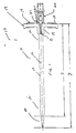
FIG. 1 is a side view of a medical introducer device which incorporates a single
layer peelable sheath in a preferred embodiment of the present invention.
-
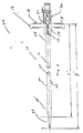
FIG. 2 is a side view of a medical introducer device which incorporates a multi-layer
peelable sheath in an alternate preferred embodiment of the present invention.
DETAILED DESCRIPTION
-
As discussed above, the present invention provides single and multi-layer
peelable sheaths for use in medical devices such as cannulas and other introducer
devices. Introducer devices are routinely used in a variety of medical and surgical
applications, e.g., for insertion of an ancilliary medical device such as a catheter, guide
wire into a patient. The present invention employs a precision sintering process in order
to produce sheaths having excellent tear properties and optimal peelability.
-
Preferred sheaths of the invention will exhibit a peel strength of at least about 0.6
lbs., more preferably at least about 0.70 lbs., still more preferably at least about 0.80
lbs., 1.0 lbs., 1.2 lbs., 1.4 lbs., 1.6 lbs., 1.8 lbs. or 2.0 lbs., with a maximum peel strength
of about 2.8 or 3.0 lbs.
-
Further preferred is where the sheath exhibits a relatively narrow standard
deviation around a tested peel strength, such a standard deviation of no more than
about ±0.40 lbs of a specific value, more preferably a standard deviation of no more than
about ±0.30 lbs, 0.20 lbs or 0.10 lbs of a specific tested value.
-
As discussed above, preferred peel strengths will vary with sheath size, with
generally higher peel strengths preferred for larger sheaths. More particularly, for a
sheath having a size up to about 9 French (typically about 2, 3, or 4 French up to about
8 or 8.5 French), preferred peel strengths will be from about 0.5 lbs. up to about 2.0 lbs.,
more preferably 0.6 lbs to about 2.0 lbs. For a sheath having a size from about 9 to
about 13 French, preferred peel strengths will be from about 0.75 lbs. up to about 2.5
lbs., more preferably 1.0 lbs to about 2.0 lbs. For a sheath having a size from about 14
to about 18 French or greater, preferred peel strengths will be from about 1.0 lbs. up to
about 3.0 lbs., more preferably 1.0 lbs to about 2.5 lbs.
-
Referring now to the Drawings, FIG. 1 shows a preferred embodiment of a
medical introducer device 10 constructed in accordance with the methods of the present
invention. Device 10 comprises a single layer, peelable sheath 11 having a proximal
end 12 and a tapered distal end 12', and a bore 13 extending therebetween. (In
accordance with conventional practice, "proximal end" designates herein the specified
end closest to the medical personnel manipulating the introducer device, and "distal end"
designates the specified end closest to the patient.)
-
Sheath 11 is formed from a polytetrafluoroethylene polymer (e.g., TEFLON,
registered trademark for polytetrafluoroethylene, commercially available from DuPont).
Sheath 11 may further comprise materials such as fillers, colorants, and the like. Typical
additional additives to the PTFE will be inorganic materials. It also will be possible,
although typically less preferred, to include additional organic materials, particularly high
Tg polymers, with the PTFE.
-
As discussed above, sheath 11 preferably further comprises a detectable
material, e.g., a radiopaque material, in an amount sufficient for external visualization by
X-ray or fluoroscopic procedures. Preferred radiopaque materials include barium
sulfate, tungsten, bismuth sub-carbonate and bismuth trioxide. Preferably, the amount
of radiopaque material present in the inner layer ranges from about 1% or 2% to about
12% by weight. Such a configuration permits visualization of the sheath within a patient
by X-ray or fluoroscopic procedures.
-
Referring now to FIG. 2, an alternate embodiment of a medical introducer device
of the present invention is shown. Device 20, constructed in accordance with the
methods of the present invention, is shown to include a multi-layer, peelable sheath 23
having a proximal end 24 and a tapered distal end 24', and a bore 25 extending
therebetween.
-
Sheath 23 preferably includes a thermally stable outer layer 26 and at least one
inner layer 27. Preferably, both of these layers are formed from a flexible polymeric
material, preferably a polytetrafluoroethylene polymer (e.g., TEFLON, registered
trademark for polytetrafluoroethylene, commercially available from DuPont).
-
In preferred embodiments of the present invention, outer layer 26 further
comprises a pigment that is not discolored by thermal processes.
-
In preferred embodiments of the present invention, inner layer 27 further
comprises a detectable material, e.g., a radiopaque material, in an amount sufficient for
external visualization by X-ray or fluoroscopic procedures. Preferred radiopaque
materials include barium sulfate, tungsten, bismuth sub-carbonate and bismuth trioxide.
Preferably, the amount of radiopaque material present in the inner layer ranges from
about 1 or 2% to about 12% by weight. Such a configuration permits visualization of the
sheath within a patient by X-ray or fluoroscopic procedures.
-
In particularly preferred embodiments, inner layer 27 additionally comprises a
pigment (e.g., different in color from that of the outer layer) for visual distinction from
outer layer 26.
Referring now to both FIGS. 1 and 2, devices of the present invention preferably
further comprise a hub unit 14 attached, e.g., molded, to the sheath at a proximal end
thereof. The hub unit 14 is capable of splitting the sheath upon application of an
effective shearing force thereon.
-
Preferably, hub unit 14 is formed of polypropylene or other suitable material. In
preferred embodiments, hub unit 14 substantially circumscribes the proximal end of the
respective sheath and comprises a longitudinal score or indentation 15 on opposing
sides. In that way, the hub is in contact with a significant circumferential surface area at
the proximal end of the respective sheaths and a defined break line is presented for
easy tearing of the sheath, e.g., along a longitudinal area 16. Using such a
configuration, the potential for the sheath to tear unevenly or incompletely is avoided or
at least significantly reduced.
-
In preferred embodiments of the present invention, two or more wing portions 17
and 18 are attached, e.g., molded to the hub unit 14. Wing portions 17 and 18
preferably extend outwardly from the hub unit in substantially diametrically opposed
positions. Wing portions 17 and 18 facilitate easy grasping with respect to hub unit 14
and effective shearing of sheath 11 and sheath 23.
-
It also is particularly preferred that the outer surfaces of wing portions 17 and 18
include topography to aid in manipulation and overall handling of the introducer device.
For example, as shown in the illustrative embodiments of FIGS. 1 and 2, preferably the
exposed sides of wing portions 17 and 18 have a plurality of raised gripping surfaces 19.
-
In particularly preferred embodiments of the present invention, raised gripping
surfaces 19 or other area(s) of wing portions 17 and 18 are color-coded to designate
particular sheath dimensions. This feature enables easy identification by attendant
medical personnel of a desired sheath size.
-
Sheaths 11 and 23 are typically adapted to snugly receive a conventional dilator
assembly 20 or alternately, a needle assembly (not shown) in order to facilitate entry into
a vein or artery of a patient.
-
Accordingly, in preferred embodiments of the present invention, wing portion 17
further comprises a locking lip 21 which secures flange 22 of dilator assembly 20 or a
comparable flange of a needle assembly.
-
Generally, distal end 28 of dilator assembly 20 extends beyond the tapered distal
end of the sheath in order to minimize trauma to the vasculature of the patient during the
procedure.
-
Preferably, dilator assembly 20 is formed from a fluorinated ethylene-propylene
resin. Other preferred fluorinated resins include, e.g., a tetrafluoroethylene polymer
such as TEFLON (registered trademark of DuPont for polytetrafluoroethylene).
-
Following dilation of the vasculature of the patient, dilator assembly 20 is
withdrawn and replaced with the desired ancilliary medical device, e.g. catheter or
guidewire. Upon application of force to the hub unit 14 via wing portions 17 and 18, the
sheath is peeled along longitudinal tear line 16 leaving only the ancilliary medical device
in place within the vasculature of the patient.
-
Suitable dimensions of the components of devices of the present invention can
vary rather widely depending on the intended application and such dimensions can be
readily determined by those skilled in the art based on the present disclosure.
Generally, dilator assembly 20 (or, alternately, a needle assembly) should have a
diameter suitable for insertion into the selected vasculature of a patient. Sheath 11 and
sheath 23 should have a diameter sufficient to accommodate such an assembly, and
subsequently a catheter, guide wire or the like. Also, the diameters of the dilator as well
as the sheath for circumscribing the dilator will be greater than the corresponding
diameters of a device that employs a percutaneous needle rather than a dilator
assembly.
-
For example, in particularly preferred embodiments of the present invention,
peelable sheath 11 is about 5 to about 6 inches in length, denoted as x in FIG. 1.
Preferably, dilator assembly 20 has a useable length (length excluding luer threads or
other connector at proximal end 28) from about 7 inches to about 8 inches, denoted as y
in FIG. 1.
-
Comparable dimensions, denoted by x' and y' in FIG. 2, are suitably preferred for
the multi-layer embodiment 20.
-
Other preferred dimensions for devices of the present invention are shown in
Table 1 below.
| | DILATOR | SHEATH |
| FRENCH SIZE | O.D. AVG. (%/& .001) | TIP I.D. MIN. (+.002/ -.000) | O.D. AVG. (%/& .001) | I.D. MIN | WALL |
| 4F | .052 | .027 | .076 | .054 | .008/.009 |
| 5F | .066 | .037 | .090 | .068 | .008/.009 |
| 6F | .079 | .037 | .103 | .081 | .008/.009 |
| 7F | .092 | .040 | .118 | .094 | .009/.010 |
| 8F | .105 | .040 | .131 | .107 | .009/.010 |
| 9F | .118 | .040 | .144 | .120 | .009/.010 |
| 10F | .131 | .040 | .159 | .133 | .010/.011 |
| 10.5F | .137 | .040 | .165 | .139 | .010/.011 |
| 11F | .144 | .040 | .172 | .146 | .010/.011 |
| 12F | .157 | .040 | .185 | .159 | .010/.011 |
| 12.5F | .162 | .040 | .192 | .164 | .011/.012 |
| 13F | .170 | .040 | .200 | .172 | .011/.012 |
| 14F | .184 | .040 | .214 | .186 | .011/.012 |
| 15F | .196 | .040 | .227 | .198 | .011/.012 |
| 16F | .210 | .040 | .240 | .212 | .011/.012 |
| 18F | .236 | .040 | .266 | .238 | .011/.012 |
-
The present invention also provides methods of manufacturing single or multi-layer
peelable sheaths for use in medical devices such as cannulas and other introducer
devices, e.g., sheaths for insertion of a catheter, guide wire and the like into a patient.
Methods of the present invention incorporate extrusion followed by a precision sintering
process in order to achieve optimally cured tubing for use as a peelable sheath. Thus,
there is no need to mechanically skive the wall of the tubing to present a weakened,
predetermined break line.
-
In the case of the multi-layer peelable sheath, methods of the present invention
preferably also comprise adding different colored pigments to each of the outer and
inner layer preform blends. Generally, such pigments are added in amounts which are
sufficient to produce the desired colors. In that way, though inseparable, the layers may
be visibly distinguished.
-
The multi-layer configuration presents significant advantages with respect to the
devices of the prior art. In particular, we have discovered that if the sheath consists of a
co-extrusion (two or more layers), it is possible to make any color sheath and that there
is no visible discoloration of the external layer after thermal tipping. Thus, there is no
need for devices of the present invention to be limited to a narrow range of colors (e.g.,
to dark colors only). Further, the ability to produce sheaths in lighter colors has the
added advantage of enabling one to visualize contaminants that may be present in the
sheath.
-
Preferably, a hydrocarbon lubricant is added to the preform blends, and the
preform blends are allowed to equilibrate for a period of several hours prior to their
combination in the case of the multi-layer sheath or prior to extrusion in the case of the
single layer sheath.
-
Sheaths of the present invention are produced using standard single or multi-layer
polytetrafluoroethylene (PTFE) extrusion procedures. For example, the two layer
PTFE extrusion process is typically used to make fuel tubes with carbon-filled PTFE on
the inside and natural PTFE on the outside. In utilizing this process, the present
invention presents an improvement in terms of thermal resistance and color integrity of
tubing.
-
As noted above, curing of the tubing is performed using a precision sintering
process, e.g., reduced sintering. We have discovered that reduced sintering provides
single or multi-layer tubing with excellent tear properties and optimal peelability. In
contrast to the prior art, using the methods of the present invention, no skiving of the
tubing is necessary to produce a peelable sheath.
-
Using the precision sintering process, the tubing is run through a series of
temperature adjusted sintering ovens in order to produce tubing which is not only cured
to the desired degree but which also has optimal tear properties, e.g., tensile strength
and elongation, as well as peel strength.
-
Typically, the peel strength and other properties of the tubing are manually
monitored at various intervals during the reduced sintering process. Various temperature
adjustments and sintering times may be employed in order to produce tubing having the
desired properties. However, the tubing is cured only until the desired peel strength is
obtained.
-
Optimal peel strength will vary with tubing size. Referring to Table 2 below,
target peel values are shown for various tubing sizes.
| FRENCH SIZE | PEEL VALUE | STANDARD DEVIATION |
| 4F-8.5F | 0.85 | +/- 0.50 lbs. |
| 9F-13F | 1.25 | +/- 0.50 lbs. |
| 14F-18F | 1.80 | +/- 0.60 lbs. |
-
In preferred embodiments of the present invention, methods of manufacture
further comprise attaching, e.g., molding, a hub unit onto the proximal end of the sheath
which facilitates splitting of the sheath upon application of an effective shearing force
thereon; attaching and a plurality of wing portions to opposing sides of the hub unit; and
tipping the sheath at a distal end thereof, e.g., using conventional thermal tipping
processes.
-
The present invention also provides methods of introducing an ancilliary medical
device, e.g., catheter or guidewire, using a device of the present invention. Such
methods generally include: inserting a needle or dilator assembly into a peelable sheath
constructed in accordance with methods of the present invention; piercing and dilating
the vasculature of the patient using such an assembly; withdrawing the needle or dilator
assembly from the sheath component of the device; inserting the catheter or guide wire
through the bore of the sheath to the desired target location; applying outwardly
cooperating forces to the hub unit, e.g., via attached wing portions, to axially shear the
sheath; and removing the sheath from the vasculature of the patient.
Particularly preferred embodiments of the invention are as follow:
-
A medical introducer device comprising:
- (a) a single-layer, peelable PTFE sheath having a bore extending therethrough and that
does not include mechanically produced skiving for longitudinal splitting of the
sheath, the sheath thermally cured to provide a peel strength of at least about 0.5 lbs
with a standard deviation of no greater than about 0.40 lbs; and
- (b) a hub unit attached at a proximal end of the peelable sheath which facilitates splitting
of the peelable sheath upon application of an effective shearing force thereon.
-
-
The device as recited above wherein the sheath has a peel strength of at least
about 0.70 lbs, preferably at least about 1.0 lbs.
-
The device as recited above wherein the sheath has a peel strength standard
deviation of no more than about 0.30 lbs, preferable no more than about 0.20 lbs.
-
The device as recited above further comprising a plurality of wing portions
attached to the hub unit on opposing sides for grasping the hub unit.
-
The device as recited above wherein the peelable sheath comprises a detectable
material capable of external visualization.
-
The device as recited above further comprising a needle or dilator assembly
extending longitudinally within the bore of the peelable sheath.
-
A medical introducer device comprising:
- (a) a multi-layer, peelable PTFE sheath having a bore extending therethrough, and that
does not include mechanically produced skiving for longitudinal splitting of the
sheath, the sheath thermally cured to provide a peel strength of at least about 0.5 lbs
with a standard deviation of no greater than about 0.40 lbs; and
- (b) a hub unit attached at a proximal end of the peelable sheath which facilitates splitting
of the peelable sheath upon application of an effective shearing force thereon.
-
-
The device as recited above wherein the sheath has a peel strength of at least
about 0.70 lbs, preferably at least about 1.0 lbs.
-
The device as recited above wherein the sheath has a peel strength standard
deviation of no more than about 0.30 lbs, preferable no more than about 0.20 lbs.
-
The device as recited above further comprising a plurality of wing portions
attached to the hub unit on opposing sides for grasping the hub unit.
-
The device as recited above further comprising a needle or dilator assembly
extending longitudinally within the bore of the peelable sheath.
-
The device as recited above wherein the multi-layer, peelable sheath comprises
a thermally stable outer layer and at least one inner layer, said inner layer comprising a
detectable material capable of external visualization and said thermally stable outer layer
of the peelable sheath comprising a pigment.
-
Especially preferred is a medical introducer device as recited above wherein the
outer layer and inner layer of the peelable sheath each comprise visibly distinct
pigments.
-
A method of manufacturing a single-layer, peelable PTFE sheath that does not
include mechanically produced skiving for longitudinal splitting of the sheath, the method
comprising:
- (a) providing a PTFE preform material;
- (b) extruding the preform material into tubing;
- (c) drying the tubing; and
- (d) curing the tubing to provide a peel strength of at least about 0.5 lbs with a standard
deviation of no greater than about 0.40 lbs.
-
-
The method as recited above further comprising adding a detectable material to
the preform blend in an amount sufficient to facilitate external visualization by X-ray or
fluoroscopic procedures.
-
The method as recited above further comprising:
- (a) affixing a hub unit onto a proximal end of the peelable sheath;
- (b) attaching a plurality of wing portions to opposing sides of the hub unit; and
- (c) tipping the peelable sheath at a distal end thereof.
-
-
The method as recited above wherein the tipping comprises thermally treating
the sheath.
-
A method of manufacturing a multi-layer, PTFE peelable sheath that does not
include mechanically produced skiving for longitudinal splitting of the sheath, comprising:
- (a) preparing a first preform PTFE material for forming the inner layer of the peelable
sheath;
- (b) preparing a second preform PTFE material for forming the outer layer of the peelable
sheath;
- (c) combining the first preform material and second preform material blend into a two
layer preform;
- (d) extruding the two layer preform into tubing;
- (e) drying the tubing; and
- (f) curing the tubing using a precision sintering process.
-
-
The method as recited above further comprising equilibrating the first preform
material and second preform material prior to their combination.
-
The method as recited above further comprising adding a detectable material to
the first preform blend in an amount sufficient to facilitate external visualization.
-
The method as recited above further comprising adding a colored pigment to at
least one of the first preform material and the second preform material.
-
The method as recited above further comprising:
- (a) affixing a hub unit onto a proximal end of the peelable sheath;
- (b) attaching a plurality of wing portions to opposing sides of the hub unit; and
- (c) tipping the peelable sheath at a distal end thereof, preferably using a thermal
process.
-
-
The device of the invention is particularly useful in a method of introducing a
catheter or guide wire into a patient comprising:
- (a) providing a medical introducer device comprising a singel-layer, peelable PTFE
sheath as described above;
- (b) piercing and dilating the vasculature of the patient using the needle or dilator
assembly;
- (c) inserting the catheter or guidewire through the bore of the peelable sheath into
vasculature of the patient;
- (d) applying cooperating forces to the wing portions of the hub unit to axially shear the
peelable sheath; and
- (e) removing the peelable sheath from the vasculature of the patient.
-
-
The device of the invention is particularly useful in a method of introducing a
catheter or guide wire into a patient comprising:
- (a) providing a medical introducer device of comprising a multi-layer, peelable PTFE
sheath as described above;
- (b) piercing and dilating the vasculature of the patient using the needle or dilator
assembly;inserting the catheter or guidewire through the bore of the peelable sheath
into vasculature of the patient;
- (c) applying cooperating forces to the wing portions of the hub unit to axially shear the
peelable sheath; and
- (d) removing the peelable sheath from the vasculature of the patient.
-
-
The following non-limiting examples are illustrative of the invention.
Example 1.
-
25 lb. of PTFE fine powder (Teflon® 6C, DuPont) was mixed with 4.35 lb. of a
hydrocarbon lubricant (Isopar® G, Exxon), 3.245 lb. of a radioopaque filler (67% Bi2O3
in Isopar G), 0.5 lb. of Gray pigment concentrate ( 67% gray pigment in Isopar G) and
0.25 lb. of black pigment concentrate (67% black pigment in Isopar® G). (Final
composition is 7.8% Bi2O3, 1.2% gray, 0.6% black, based on total solids) These
ingredients were mixed in a Patterson-Kelly V-cone blender for 20 minutes. This mix
was then allowed to age for several hours to equilibrate.
-
The blend was made into a preform (2.5" OD, 0.625" ID). The object of
preforming is to compact the blends in size and to make a preform that can be inserted
into an extrusion machine. The preform was placed into an extrusion machine and
extruded into tubing using a die and mandril (0.2880"OD, 0.2650"ID). The tubing was
run through a drying oven to remove the hydrocarbon lubricant. The tubing was then run
through 3 sintering ovens to cure the material. This tubing was then cut into 8.25"
lengths.
-
The tubing produced had dimensions of 0.240" OD x 0.2170" ID x 8.25" long.
The wall thickness was 0.0115". The overall tube was black with a shiny surface.
-
Referring to Table 3 below, properties of the tubing produced in this example are
shown below as "Sample 2". Data for Samples 1, 3 and 4 are shown for purposes of
comparison.
| | SAMPLE 1 | SAMPLE 2 | SAMPLE 3 | SAMPLE 4 |
| | PRIOR ART SAMPLE | PRESENT INVENTION | UNDERCURE | OVERCURE |
| Drying oven 1 (F) | 400 | 400 | 400 | 400 |
| Curing oven 1 (F) | 840 | 720 | 700 | 1000 |
| Curing oven 2 (F) | 940 | 820 | 800 | 1080 |
| Curing oven 3 (F) | 1040 | 920 | 900 | 1180 |
| Melting Point (C) | 326.63 | 326.57 | 343.77 | 326.03 |
| Width at Half Height (C) | 4.0 | 6.0 | 5.6 | 3.3 |
| Tensile Strength (PSI) | 7083 | 6817 | 1333 | 5417 |
| Elongation (%) | 288 | 309 | 233 | 351 |
| Peel strength (lb) | 1.95 | 1.56 | 1.2 | 2.67 |
| Peel Comments | Uneven peel, partial peel | Straight, even peel | Straight, even peel. Lots of stringers. | Uneven peel, partial peel |
Description of Samples:
-
- Sample 1 - This sample is presented for purposes of comparison. It is a commercially
available product comprising PTFE, and has a narrow melting point peak at 327 degrees
C. When split and peeled, it requires higher peel force and does not peel smoothly. The
tubing begins to peel and then one of the sections begins to narrow down and eventually
ends before all of the tubing is split (partial peel).
- Sample 2 - This sample corresponds to a peelable product manufactured in accordance
with the methods of present invention. This product is not fully cured as indicated by the
wider melting point peak. The tensile strength and elongation are similar to the fully
cured product. However, the peel strength is reduced by 20% in relation to the fully
cured product. The peel is straight and even so that the entire tubing is split.
- Sample 3 - This sample corresponds to a product that is almost completely uncured.
This is visible by a melting peak at 344 degrees C versus 327 degrees C for the other
samples. This product is mottled white and black due to the undercure. The peel is
straight and even, however, there are significant numbers of fibers that extend from the
peeled surface after peeling. This is unacceptable to the end user since a piece may
tear away and contaminate the area. In addition, the physical properties are significantly
reduced due to the lack of curing of the product.
- Sample 4 - This sample corresponds to a product that is cured harder than normal. This
overcure is visible by the melting peak half width. This product does not peel straight,
similar to the fully cured product.
-
Example 2.
-
Blend 1 - 55.1 lb. of PTFE fine powder (Teflon® 6C, DuPont) was mixed with
9.048 lb. of a hydrocarbon lubricant (Isopar® G, Exxon), and 7.151 lb. of a radiopaque
filler (67% Bi2O3 in Isopar G) (final composition is 6.7% Bi2O3 based on total solids).
These ingredients were mixed in a Patterson-Kelly V-cone blender for 20 minutes. This
mix was then allowed to age for several hours to equilibrate.
-
Blend 2 - 55.1 lb. of PTFE fine powder (Teflon® 6C, DuPont) was mixed with
10.379 lb. of a hydrocarbon lubricant (Isopar® G, Exxon), and .573 lb. of a white
pigment filler (67% white pigment in Isopar G). These ingredients were mixed in a
Patterson-Kelly V-cone blender for 20 minutes. This mix was then allowed to age for
several hours to equilibrate.
-
The blends were made into a two layer preform (2.5" OD, 0.625" ID) with Blend 1
on the ID and Blend 2 on the OD. The object of preforming is to compact the blends in
size and to make a preform that can be inserted into an extrusion machine. The preform
was placed into an extrusion machine and extruded into tubing using a die and mandril.
(0.2880"OD, 0.2650"ID) The tubing was run through a drying oven to remove the
hydrocarbon lubricant. The tubing was then run through 3 sintering ovens to cure the
material. This tubing was then cut into 8.25" lengths.
-
The tubing produced has dimensions of 0.240" OD x 0.2170" ID x 8.25" long.
The wall thickness is 0.0115". The overall tube is two layers with a shiny white outside
layer and a yellow inside layer.
| | SAMPLE 1 | SAMPLE 2 | SAMPLE 3 |
| | PRESENT INVENTION | UNDERCURE | OVERCURE |
| Drying oven 1 (F) | 400 | 400 | 400 |
| Curing oven 1 (F) | 820 | 720 | 1000 |
| Curing oven 2 (F) | 920 | 820 | 1160 |
| Curing oven 3 (F) | 1000 | 920 | 1160 |
| Melting Point (C) | 325.96 | 343.33 | 329.38 |
| Tensile Strength (PSI) | 7000 | 1333 | 7400 |
| Elongation (%) | 250 | 250 | 350 |
| Peel strength (lb) | 1.56 | 0.4 | >2.5* |
| Peel Comments | Straight, even peel | Straight, even peel. Lots of stringers. | *Could not peel. |
Description of Samples:
-
- Sample 1 - This is an example of the present invention. This is a peelable product.
This product is precision sintered. The peel strength is typical for precision sintered
product. The peel is straight and even so that the entire tubing is split.
- Sample 2 - This sample is almost completely uncured product. This is visible by a
melting peak at 344 degrees C versus 327 degrees C for the other samples. This
product is opaque, dull white due to the undercure. The peel is straight and even,
however, there are significant numbers of fibers that stick out of the peeled surface after
being peeled. The peel strength is unacceptably low. This is unacceptable to the end
user since a piece may tear away and contaminate the area. In addition, the physical
properties are significantly reduced due to the lack of curing of the product.
- Sample 3 - This product is fully cured. This makes a tube that is dimensionally stable,
but cannot be peeled. The peel force increases to greater than 2.5 lb. and then the
product tears. This product does not peel evenly.
-
Example 3.
-
Tubing manufacturing: Blend 1 - 25 lb. of PTFE fine powder (Teflon® T6C,
DuPont) was mixed with 4.5 lb. of a hydrocarbon lubricant (Isopar® G, Exxon) and 3.3
lb. of a radiopaque filler (67% Bi2O3 in Isopar G, Caloric) in a Patterson-Kelly V-cone
blender. The materials were blended for 20 minutes. This mix was then allowed to age
for several hours to equilibrate.
-
Blend 2 - 25 lb. of PTFE fine powder (Teflon® T6C, DuPont) was mixed with 5.1
lb. of a hydrocarbon lubricant (Isopar® G, Exxon) and 0.3 lb. of a white pigment (67%
white pigment in Isopar G, Caloric) in a Patterson-Kelly V-cone blender. The materials
were blended for 20 minutes. This mix was then allowed to age for several hours to
equilibrate.
-
The two blends were then made into a two layer preform (2.5" OD, 0.625" ID)
with Blend 2 on the OD and Blend 1 on the ID. (The object of preforming is to compact
the blends in size and to make a preform that can be inserted into an extrusion
machine.) The preform was placed into an extrusion machine and extruded into tubing.
The tubing was run through a drying oven at approximately 400 degrees F to remove the
hydrocarbon lubricant. The tubing was then run through sintering ovens at
approximately 1000 degrees F to cure the material. This tubing was cut into 8.25"
lengths.
-
The tubing produced had dimensions of 0.144" OD x 0.125" ID x 8.25" in length
with a wall thickness of 0.0095". The outer 0.00475" was Blend 2 and the inner 0.00475"
was Blend 1. The overall tube had a white color with a yellow inside when cut apart.
-
Device manufacture: The tubing was then punched with two holes. A slit was
made between the two holes. Buttons were placed in the punched holes and a hub was
overmolded onto the tubing. The opposite end was then tipped using a Rf tipping
machine and trimmed to size. The finished sheath assembly was white in color with no
visible discoloration. The sheath assembly was then placed over a matching size dilator.
Example 4.
-
This example shows how additional heat added to a precision sintered product
renders it useless for peelable PTFE. The table illustrates that precision sintered
product can be taken out of the useful range by the application of additional heat. It also
shows that skived product is not affected by the addition of additional heat.
| | SAMPLE 1 | SAMPLE 2 | SAMPLE 3 |
| Skived | No | No | Yes |
| Precision sintered | Yes | Yes | Yes |
| Post cured | No | Yes | Yes |
| Peel Strength (lb.) | 1.63 | 2.93 | 1.26 |
| Peel Comments | Straight, even peel | Uneven peel, partial peel | Straight even peel |
Description of Samples:
-
- Sample 1 - Product from Example 1, Sample 2.
- Sample 2 - Product from Example 1, Sample 2 was taken and placed in a 700 degree F
oven for 20 minutes. This product is no longer precision sintered since it was post-sintered.
- Sample 3 - Product from Example 1, Sample 2 that was skived and then placed in a 700
degree F oven for 20 minutes. This product is no longer precision sintered since it was
post-sintered.
-
Comparative Example 1.
-
The tubing was made identical to Example 3 except that instead of using Blend 2
on the OD, Blend 1 was used for the entire preform. Thus, one layer of tubing is
produced that is Blend 1 throughout. This produced tubing that was yellow in color.
-
The tubing was finished in the same manner as listed in Example 3. The finished
sheath assembly was yellow in color with brown and black colored spots in the tipped
section. This is unacceptable for high quality product.
Comparative Example 2.
-
Blend 3 is a combination of Blend 1 and Blend 2 - 25 lb. of PTFE fine powder
(Teflon® T6C, DuPont) was mixed with 4.4 lb. of a hydrocarbon lubricant (Isopar® G,
Exxon), 3.3 lb. of a radiopaque filler (67% Bi2O3 in Isopar G, Caloric), and 0.3 lb. of a
white pigment (67% white pigment in Isopar G, Caloric) in a Patterson-Kelly V-cone
blender. The materials were blended for 20 minutes. This mix was then allowed to age
for several hours to equilibrate.
-
The tubing was made identical as that described in Comparative Example 1
except that instead of using Blend 2, Blend 3 was used. This produced tubing that was
white in color and radiopaque.
-
The tubing was finished in the same manner as described in Example 3. The
finished sheath assembly was white in color with brown and black colored spots in the
tipped section. This is unacceptable for high quality product.
-
The foregoing description of the present invention is merely illustrative thereof,
and it is understood that variations and modification can be made without departing from
the spirit or scope of the invention as set forth in the examples and claims.