EP1125549B1 - Catheter for generating an electrical map of a chamber of the heart - Google Patents
Catheter for generating an electrical map of a chamber of the heart Download PDFInfo
- Publication number
- EP1125549B1 EP1125549B1 EP01301387A EP01301387A EP1125549B1 EP 1125549 B1 EP1125549 B1 EP 1125549B1 EP 01301387 A EP01301387 A EP 01301387A EP 01301387 A EP01301387 A EP 01301387A EP 1125549 B1 EP1125549 B1 EP 1125549B1
- Authority
- EP
- European Patent Office
- Prior art keywords
- catheter
- location
- contact
- heart
- location sensor
- Prior art date
- Legal status (The legal status is an assumption and is not a legal conclusion. Google has not performed a legal analysis and makes no representation as to the accuracy of the status listed.)
- Expired - Lifetime
Links
Images


Classifications
-
- A—HUMAN NECESSITIES
- A61—MEDICAL OR VETERINARY SCIENCE; HYGIENE
- A61B—DIAGNOSIS; SURGERY; IDENTIFICATION
- A61B5/00—Measuring for diagnostic purposes; Identification of persons
- A61B5/24—Detecting, measuring or recording bioelectric or biomagnetic signals of the body or parts thereof
- A61B5/25—Bioelectric electrodes therefor
- A61B5/279—Bioelectric electrodes therefor specially adapted for particular uses
- A61B5/28—Bioelectric electrodes therefor specially adapted for particular uses for electrocardiography [ECG]
- A61B5/283—Invasive
- A61B5/287—Holders for multiple electrodes, e.g. electrode catheters for electrophysiological study [EPS]
-
- A—HUMAN NECESSITIES
- A61—MEDICAL OR VETERINARY SCIENCE; HYGIENE
- A61M—DEVICES FOR INTRODUCING MEDIA INTO, OR ONTO, THE BODY; DEVICES FOR TRANSDUCING BODY MEDIA OR FOR TAKING MEDIA FROM THE BODY; DEVICES FOR PRODUCING OR ENDING SLEEP OR STUPOR
- A61M25/00—Catheters; Hollow probes
Definitions
- the invention is directed to apparatus and associated catheters for rapidly generating an electrical map of a chamber of a heart utilizing an array of non-contact electrodes for obtaining information indicative of chamber electrical activity, and optionally, of chamber geometry.
- the preliminary map is often combined with data taken at additional points in order to generate a more comprehensive map of the heart's electrical activity.
- the generated detailed map may then serve as the basis for deciding on a therapeutic course of action, for example, tissue ablation, to alter the propagation of the heart's electrical activity and to restore normal heart rhythm.
- Catheters containing position sensors may be used to determine the trajectory of points on the cardiac surface. These trajectories may be used to infer motion characteristics such as the contractility of the tissue. As disclosed in U.S. patent 5,738,096, maps depicting such motion characteristics may be constructed when the trajectory information is sampled at a sufficient number of points in the heart.
- Electrode activity at a point in the heart is typically measured by advancing a catheter containing an electrical sensor at or near its distal tip to that point in the heart, contacting the tissue with the sensor and acquiring data at that point.
- One drawback with mapping a cardiac chamber using a catheter containing only a single, distal tip electrode is the long period of time required to accumulate data on a point-by-point basis over the requisite number of points required for a detailed map of the chamber as a whole. Accordingly, multiple-electrode catheters have been developed to simultaneously measure electrical activity at multiple points in the heart chamber.
- U.S. Patent 5,487,391 directed to systems and methods for deriving and displaying the propagation velocities of electrical events in the heart, is illustrative of contact methods found in the art.
- the electrical probe is a three-dimensional structure that takes the form of a basket.
- the basket is composed of 8 splines, each of which carries eight electrodes, for a total of 64 electrodes in the probe.
- the basket structure is designed such that when deployed, its electrodes are held in intimate contact against the endocardial surface.
- a problem with the catheters disclosed in the '391 patent is that they are both difficult and expensive to produce. The large number of electrodes in such catheters is also very demanding of the data recording and processing subsystem. There are additional complexities associated with the deployment and withdrawal of these catheters, and increased danger of coagulation.
- U.S. Patent 5,848,972 to Triedman et al. discloses a method for endocardial activation mapping using a multi-electrode catheter.
- a multi-electrode catheter preferably, a 50-electrode Webster-Jenkins TM basket catheter from Cordis-Webster of Baldwin Park, CA, is advanced into a chamber of the heart.
- Anteroposterior (AP) and lateral fluorograms are obtained to establish the position and orientation of each of the electrodes. Electrograms are recorded from each of the electrodes in contact with the cardiac surface relative to a temporal reference such as the onset of the P-wave in sinus rhythm from a body surface ECG.
- Triedman et al. differentiate between those electrodes that register electrical activity and those that do not due to absence of close proximity to the endocardial wall. After the initial electrograms are recorded, the catheter is repositioned, and fluorograms and electrograms are once again recorded. An electrical map is then constructed from the above information.
- U.S. Patent 4,649,924 to Taccardi discloses a method for the detection of intracardiac electrical potential fields.
- the '924 patent is illustrative of the non-contact methods that have been proposed to simultaneously acquire a large amount of cardiac electrical information.
- a catheter having a distal end portion is provided with a series of sensor electrodes distributed over its surface and connected to insulated electrical conductors for connection to signal sensing and processing means. The size and shape of the end portion are such that the electrodes are spaced substantially away from the wall of the cardiac chamber.
- the method of the '924 patent is said to detect the intracardiac potential fields in only a single cardiac beat.
- the sensor electrodes are preferably distributed on a series of circumferences lying in planes spaced from each other. These planes are perpendicular to the major axis of the end portion of the catheter. At least two additional electrodes are provided adjacent the ends of the major axis of the end portion.
- the '924 patent discloses only a single exemplary embodiment in which the catheter comprises four circumferences with eight electrodes spaced equiangularly on each circumference.
- the catheter comprises at least 34 electrodes (32 circumferential and 2 end electrodes).
- the Rudy method involves the following steps (after the independent imaging step): (a) measuring electrical potentials with a plurality of electrodes disposed on a probe positioned in the heart; (b) determining the geometric relationship of the probe surface and the endocardial surface; (c) generating a matrix of coefficients representing the geometric relationship of the probe surface and the endocardial surface; and (d) determining endocardial potentials based on the electrode potentials and the matrix of coefficients.
- U.S. Patent 5,297,549 to Beatty et al. discloses a method and apparatus for mapping the electrical potential distribution of a heart chamber.
- an intra-cardiac multielectrode mapping catheter assembly is inserted into the heart.
- the mapping catheter assembly includes a multi-electrode array with an integral reference electrode, or, preferably, a companion reference catheter.
- the electrodes are deployed in the form of a substantially spherical array.
- the electrode array is spatially referenced to a point on the endocardial surface by the reference electrode or by the reference catheter which is brought into contact with the endocardial surface.
- the preferred electrode array catheter is said to carry at least 24 individual electrode sites.
- the Beatty method requires knowledge of the location of each of the electrode sites on the array, as well as a knowledge of the cardiac geometry. These locations are preferably determined by the method of impedance plethysmography.
- U.S. patent 5,311,866 to Kagan et al. discloses a heart mapping catheter assembly including an electrode array defining a number of electrode sites.
- the mapping catheter assembly also comprises a lumen to accept a reference catheter having a distal tip electrode assembly which may be used to probe the heart wall.
- the mapping catheter comprises a braid of insulated wires, preferably having 24 to 64 wires in the braid, each of which are used to form electrode sites.
- the catheter is said to be readily positionable in a heart to be used to acquire electrical activity information from a first set of non-contact electrode sites and/or a second set of in-contact electrode sites.
- U.S. Patents 5,385,146 and 5,450,846 to Goldreyer disclose a catheter that is said to be useful for mapping electrophysiological activity within the heart.
- the catheter body has a distal tip which is adapted for delivery of a stimulating pulse for pacing the heart or an ablative electrode for ablating tissue in contact with the tip.
- the catheter further comprises at least one pair of orthogonal electrodes to generate a difference signal indicative of the local cardiac electrical activity adjacent the orthogonal electrodes.
- EP-A 0,911,059 discloses a catheter and console combination for mapping a chamber of a heart.
- the catheter comprises a body having a proximal end and a distal end having a distal tip.
- An ablation electrode is provided at the distal tip.
- Two sensing electrodes are located adjacent the ablation electrode, the electrodes being linearly arranged along a longitudinally axis of the body.
- the catheter also includes a location sensor on the distal end of the body adapted to generate signals in response to an electromagnetic field to determine a location of the distal tip of the catheter. Activation signals sensed by the two sensing electrodes and position signals generated by the position sensor are conveyed to a signal processor in the console. The signal processor processes the signals and calculates correlation coefficients and the position of the distal tip of the catheter. Where low correlation coefficients are detected those portions of the heart chamber are ablated by the ablation electrode.
- WO 98/29032 discloses another catheter and console combination.
- the console comprises driver circuits operatively connected to electromagnetic field generators for generating an electromagnetic field.
- the console also comprises a signal processor for determining location information.
- the catheter comprises a body having a proximal end and a distal end having a distal tip.
- a contact electrode is provided at the distal tip.
- the catheter further comprises two location sensors on the distal end of the body adapted to generate signals in response to the electromagnetic field.
- the signal processor is adapted to use said generated signals to determine a location of the distal end of the catheter.
- the present invention is a novel system/apparatus for rapidly generating a map of a characteristic of an organ, such as a chamber of the heart, within a defined period of time.
- a system for mapping a chamber of a heart comprises a console, driver circuits and a catheter.
- the console comprises a signal processor for determining location information.
- the driver circuits are operatively connected to at least one electromagnetic field generator for generating an electromagnetic field.
- the catheter comprises a body having a proximal end and a distal end, the distal end having a distal tip.
- a contact electrode is provided at the distal tip.
- An array of non-contact electrodes is provided on the distal end of the body.
- the array has a proximal end and a distal end and the non-contact electrodes are linearly arranged along a longitudinal axis of the body.
- the catheter further comprises at least one location sensor on the distal end of the body adapted to generate signals in response to the electromagnetic field.
- the signal processor is adapted to use the generated signals to determine a location of the contact electrode and a location of the non-contact electrodes.
- the signal processor is adapted to determine the location of the non-contact electrodes from the signals generated by the at least one location sensor.
- the signal processor during at least an entire cardiac cycle, in a first mode of operation is adapted to acquire electrical information from only the non-contact electrodes, indicative of the locations of the non-contact electrodes, to represent a minimum chamber volume of the heart, thus to define the geometry of the heart.
- the signal processor during at least an entire cardiac cycle, in a second mode of operation is further adapted to acquire electrical information from the contact, indicative of the location of the contact electrode, to define a geometric map of the heart chamber, thus defining the chamber geometry by representing both a minimum chamber volume and a geometric map of the heart.
- the sensor is preferably proximate the catheter distal tip. More preferably, the catheter comprises first and second location sensors. The first location sensor is preferably proximate the catheter distal tip and the second location sensor is proximate the proximal end of the non-contact electrode array. At least one and preferably both of the sensors used in the catheter of the invention provides six degrees of location information.
- the location sensor used in the catheter of the invention is preferably an electromagnetic location sensor.
- the distal tip electrode used in the catheter of the invention is preferably a bipolar electrode.
- the array of non-contact electrodes preferably comprises from about 12 to about 32 electrodes, and more preferably between about 16 to about 24 electrodes.
- the present invention is a novel apparatus (system), including its associated catheter for conducting a rapid or fast mapping procedure in an organ such as the chamber of a heart. There is also disclosed a method, not forming a part of the invention, for conducting a rapid or fast mapping procedure in an organ such as the chamber of a heart.
- the present invention is directed to conducting this rapid mapping procedure, usually based on electrical activity through the heart tissue, within a minimum period of time.
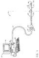
- the present invention includes a novel rapid diagnostic mapping and therapeutic delivery system, generally designated 18, as best shown in Fig. 1, comprising a novel fast diagnostic mapping and therapeutic delivery catheter 20 for insertion into the human body, and preferably, into a chamber 56 and 66 (Figs. 5 and 7A) of a human heart 29 (Figs. 2, 7A and 7B).
- the catheter 20 includes a catheter body 20a having a distal end 22.
- the distal end 22 includes an electrode 24 at distal tip 26 for measuring the electrical properties of the heart tissue.
- Electrode 24 is also useful for sending electrical signals to the heart for diagnostic purposes, e.g., for pace mapping, and/or for therapeutic purposes, e.g., for ablating defective cardiac tissue.
- Catheter 20 preferably includes a handle 30, which includes controls 32 to steer the distal end 22 of the catheter 20 in a desired direction, such as deflecting the distal end 22, or to position and/or orient it as desired.
- the system 18 as shown in Fig. 1 further comprises a console 34, which enables the user to observe and regulate the functions of catheter 20.
- Console 34 preferably includes a computer 36 (as a signal processor), keyboard 38, signal processing circuits 40 which are typically inside the computer, and display 42.
- Signal processing circuits 40 typically receive, amplify, filter and digitize signals from catheter 20, including signals generated by location sensor 28, tip electrode 24 and non-contact electrodes 25 whereupon these digitized signals are received and used by computer 36 to compute the position and orientation of the catheter as well as the electrical characteristics of the heart chamber.
- appropriate circuitry may be associated with the catheter 20 itself so that circuits 40 receive signals that are already amplified, filtered and/or digitized.
- Catheter 20 is coupled to computer 36 via an extension cable 21, which at its proximal end comprises a connector 44 adapted to fit in a mating receptacle 46 on console 34.
- the distal end of cable 21 comprises a receptacle 33 which connects to catheter handle 30.
- Receptacle 33 is preferably configured to receive catheters of a specific model, and preferably includes user-evident identification of the specific model.
- One of the advantages in using cable 21 is the ability to connect different models and types of catheters, such as those catheters having different handle configurations, to the same console 34. Different cables 21 can be used to connect a large variety of catheters to console 34.
- Another advantage in having a separate cable 21 is in the fact that the cable 21 does not come into contact with patients and therefore it is possible to re-use the cable 21 without sterilization.
- Cable 21 further contains one or more isolation transformers (not shown in the figures), which electrically isolate catheter 20 from console 34.
- the isolation transformers are preferably contained in receptacle 33. Alternatively, isolation transformers may be contained in the associated system electronics.
- FIG. 2 Additional components used in system 18 with catheter 20 of the present invention are illustrated schematically in Fig. 2.
- a physician 100 inserts catheter 20 through an incision in the vasculature, e.g., using an intravascular approach, into a chamber 56 and 66 (Figs 5, 7A and 7B) of a heart 29 of a patient 110, so that distal tip electrode 24, array 23 of non-contact electrodes 25 and location sensor 28 are inside the chamber.
- a location sensor described in PCT patent application number WO 96/05768, filed January 24, 1995, and U.S.
- patent 5,391,199 which are assigned to the assignee of the present application sensor 28 generates signals in response to externally applied magnetic fields generated by electromagnetic field generator coils 27 which are located near the patient 110 such as fixed to operating table 31.
- the magnitude of the signals generated by sensor 28 depends on the position and orientation of the sensor in the applied magnetic field.
- Field generator coils 27 are connected via cable 41 to driver circuits 43.
- Circuits 43 are connected to computer 36 (Fig. 1), which controls the operation of the generating coils.
- the system of the invention may employ field generator coils in the catheter and sensors external to the patient.
- any other location sensor that provides three-dimensional position information and, optionally, orientation information may be used in the practice of the invention.
- Illustrative sensors that are also useful include acoustic sensors and magnetic sensors.
- measurements by location sensor 28 are substantially synchronized with the heart cycle, so that the resultant maps of electrical activity of the heart chamber 56 and 66 depict the chamber geometry at a single point in the heart cycle.
- the maps depict the heart 29 at the end-diastole point in the heart cycle. Synchronization of the locations to a point in the cardiac cycle eliminates errors that may otherwise arise in determining positions of contact electrode 24 and non-contact electrodes 25 due to movement of the heart 29.
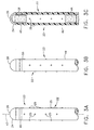
- Figure 3A is a plan view of the distal end of one preferred embodiment of the catheter of the invention.
- Fig. 3B depicts the catheter of Fig. 3A rotated by 90° about its longitudinal axis 47.
- Fig. 3C depicts the catheter of Fig. 3B in cross-section along line 3B-3B.
- the catheter comprises tip electrode 24 and ring electrode 45. Together, these two electrodes function as a bipolar contact electrode.
- the array 23 of non-contact electrodes 25 has a proximal end 49 and a distal end 50.
- Array 23 consists of a plurality of electrodes 25, for instance, sixteen point electrodes 25.
- Each electrode 25 is circular in cross-section and has a diameter of 1 mm.
- the electrodes 25 in array 23 are arranged in four columns spaced circumferentially around the catheter distal end 22 in 90° increments. The location of the electrodes 25 in each column is longitudinally offset relative to the location of the corresponding electrodes in adjacent columns. This arrangement of non-contact electrodes 25 in array 23 allows the non-contact electrodes 25 to simultaneously receive far-field electrical signals from all walls of the chamber 56 and 66 in which the catheter 20 is advanced.
- the catheter 20 further comprises two location sensors 28 and 48 wherein sensor 28 is at the catheter distal tip and sensor 48 is near the proximal end 49 of array 23. Not shown in Fig. 3C are wires that connect each of the sensors 28 and 48 and each of the electrodes 24, 25 and 45 to handle 30, from which signals are transmitted to circuits 40.
- a deflection mechanism which permits deflection of the catheter tip via control 32 on catheter handle 30.
- the specific design of the catheter deflection mechanism is not critical to the invention, and may be any of the designs for catheter deflection mechanisms known in the art.
- Catheter steering/deflection mechanisms are disclosed, for example, in U.S. Patents 5,964,757; 5,897,529; and 5,938,603; in EP Patent Applications EP 0900547 and EP 0900548, and in PCT Patent Application WO 98/43530.
- Fig. 4 shows an alternate embodiment distal end 22a for the catheter 20 of the invention.
- the catheter 20 consists of tip electrode 24 and ring electrode 45.
- An array 23a of non-contact electrodes 25a consists of a total of twenty-four non-contact electrodes 25a arranged in four columns of six electrodes each and spaced circumferentially at 90° increments about the catheter distal end 22a.
- the non-contact electrodes 25a are rectangular in shape, having dimensions of 1 mm X 3 mm, and are spaced within a column at a distance of 8 mm between centers.
- the catheter distal end 22a of Fig. 4 likewise contains two location sensors (not shown), one at the catheter tip 24 and the other at the proximal end of electrode array 23a.
- Electrode array 23a preferably comprises from about twelve to about thirty-two non-contact electrodes 25a. More preferably, array 23a comprises from about sixteen to about twenty-four non-contact electrodes 25a. In one preferred embodiment, array 23a comprises less than twenty non-contact electrodes 25a.
- non-contact electrodes 25 and 25a in electrode arrays 23 and 23a are preferably discontinuous about the circumference of catheter distal ends 22 and 22a, respectively.
- Fig. 5 is a top plan section view of catheter 20 in heart chamber 56.
- Catheter 20 has its non-contact electrode array 23 arranged in four columns equally spaced about the catheter circumference.
- the discontinuous non-contact electrodes sense the electrical activity of distinct regions of the cardiac surface, designated as 58, 60, 62 and 64 in Fig. 5.
- non-contact electrodes that are continuous about the catheter circumference would provide signals that would represent average electrical activity in the heart chamber, from which it would be more difficult to determine local electrical activity.
- Ring electrodes are an example of a continuous electrode geometry that completely encircles the catheter circumference, and, as such, are not preferred for use as the non-contact electrodes in the practice of the invention.
- the catheter 20 according to the present invention can optionally utilize the contact electrode 24 along with the non-contact electrode arrays 23 and 23a respectively. Accordingly, it is within the scope of the present invention to conduct a rapid diagnostic mapping procedure based on electrical information received through the non-contact electrodes 25 and 25a alone. While the catheter distal ends 22 and 22a shown in Figures 3A, 3B, 3C and 4 have bipolar distal tip contact electrodes, it will be understood that catheter distal ends containing unipolar distal tip electrodes are also considered to be within the scope of the present invention.
- the catheter of the invention used in the method preferably employs two or more location sensors such as sensors 28 and 48 as shown in Fig. 3C.
- One of these sensors is preferably placed in the catheter distal tip 26 while a second sensor is preferably placed at the proximal end 49 of the non-contact electrode array.
- at least one of these location sensors provides six degrees of location and orientation information, i.e., three position coordinates ( x, y and z ) and the three orientation coordinates (pitch, roll and yaw).
- a suitable, location sensor 28 and 48 that provides six degrees of location information is described, for example in PCT application WO 96/05768.
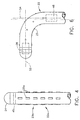
- Fig. 6 shows the catheter distal end 22 in Fig. 3B in a deflected position.
- the orientation of sensors 28 and 48 may be characterized by lines 52 and 54, which represent the axes passing through sensors 28 and 48, respectively. Knowing the three-dimensional position and orientation of each of the sensors and the geometry of the electrodes 25 at the catheter distal end 22, the position and orientation of each of the electrodes 25 may be calculated, for example, using spline techniques.
- the catheter having only a single position sensor in the practice of the method of the invention.
- the sensor is preferably located at the catheter distal tip 26.
- sensor 28 preferably senses and transmits signals indicative of six degrees of location information.
- sensor 48 may be a six-degree sensor, a sensor providing less than six degrees of location information may also be used.
- a sensor which senses five degrees of location information is described in U.S. Patent 5,913,820.
- Such sensors may be used as the second sensor proximate the proximate end 49 of electrode array 23.
- a plurality of location sensors, each providing less than six degrees of location information may be used.
- three or more location sensors, each providing three degrees of location information may be used to define the location of all points on the catheter.
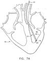
- Another aspect of the disclosed method is for rapidly generating an electrical map of a chamber 66 of the heart 29 that depicts an electrical characteristic of the chamber 66 as a function of chamber geometry within a brief time period.
- the method includes advancing the catheter 20 into the chamber 66 of the heart 29.
- the contact electrode 24 at distal tip 26 of catheter 20 is then brought into contact with wall 68 of chamber 66 at first contact point 70.
- Contact electrode 24 is maintained in contact with wall 68 at contact point 70 throughout at least an entire cardiac cycle.
- location information is continuously measured by location sensors 28 and 48, while electrical information, preferably, voltage (as a function of time), is measured by contact electrode 24 and each of the non-contact electrodes 25 in array 23.
- contact electrode 24 at the catheter tip 26 is advanced to a second contact point on the chamber surface.
- Figure 7B shows the contact electrode 24 in contact with second contact point 72 on chamber wall 68.
- Figure 7B further shows point 70, the site of the first contact point, and points 74, shown as asterisks, which represent the location of the non-contact electrodes 25 while contact electrode 24 was at first contact point 70.
- contact electrode 24 is maintained in contact with wall 68 at contact point 72 throughout at least an entire cardiac cycle, during which time location information is measured by the location sensors, and electrical information is measured by contact electrode 24 and by each of the non-contact electrodes 25.
- Contact electrode 24 is advanced over a plurality of contact points on the cardiac chamber surface, and location and electrical information is acquired while the contact electrode is in contact with each of the contact points.
- the above-described contacting and information acquisition steps are effected at at least about five contact points on the cardiac chamber surface. More preferably, the contacting and information acquisition steps are effected at between about five and about fifteen contact points on the cardiac chamber surface. Assuming that data are acquired at ten contact points, it can be seen that using the catheter of Figs. 3A-C for example, electrical data at a total of ten contact points and one hundred and sixty non-contact points (ten contact points X sixteen non-contact electrodes) would be available for the map generation step.
- the resultant location and electrical information acquired at each of the above-defined process steps provides the starting point for generating an electrical map of the heart chamber.
- the first source of information is the location of sensor 28 adjacent the catheter distal tip 26 at each of the contact points.
- the second source of information is the location of each of the non-contact electrodes while the contact electrode is in contact with each of the contact points.
- the location of the contact electrodes at each of the contact points may be used to define the geometric map of the cardiac chamber. While not actually contacting the cardiac surface, the totality of the non-contact electrode locations defines a "cloud" of space which represents a minimum chamber volume. These non-contact locations may be used, alternatively, or together with the location of the contact electrodes at each of the contact points, to define the chamber geometry.
- a reference location sensor it is preferable to use a reference location sensor to correct for patient movement during the procedure or to movement of the heart due to patient breathing.
- One method of obtaining a location reference is by the use of a reference catheter containing a reference location sensor elsewhere in the heart.
- a reference location sensor may be contained in a pad that might be attached external to the patient, for example on the back of the patient. In either case, locations determined by the sensors contained in the mapping catheter may be corrected for patient movement with the reference sensors.
- the disclosed method may likewise use the known Rudy method, as previously described, to extract endocardial potentials from electrical measurements made by the non-contact electrode array.
- data taken by the contact electrode which accurately measures endocardial potentials at the contact points, can be used to constrain the endocardial potentials determined from the non-contact electrodes.
- chamber geometry is determined by the location sensors simultaneous with the electrical measurements.
- expected endocardial potentials are computed based on measurements from the electrode array.
- the measured voltage at the surface-contacting reference electrode is used as a scaling factor in computation of the voltage map.
- the Beatty method may alternatively be used in the disclosed method to generate local endocardial potentials from the combined contact and non-contact electrode measurements.
- the resultant electrical potentials imputed to the cardiac surface by the non-contact electrode array can be used to reconstruct local endocardial electrograms. These reconstructed electrograms, together with the electrograms measured by contact electrode 24, provide the electrical information from which the electrical map of the heart chamber may be generated.
- LAT local activation time
- the local electrical characteristic that is mapped in the process of the invention is preferably referenced to a fiducial value.
- This value may, for example, be based on an electrical characteristic measured at a reference catheter elsewhere in the heart.
- the mapped electrical characteristic may be referenced to a particular feature of the body surface ECG signal.
- a processor reconstructs a map, preferably a 3-D map, of the cardiac chamber from a plurality of sampled points on the chamber whose position coordinates have been determined.
- the processor is preferably capable of reconstructing the map based on a limited number of sampled points. Preferably, five to fifteen sampled points are sufficient in order to perform a preliminary reconstruction of the surface to a satisfactory quality.
- An initial, generally arbitrary, closed 3-D curved surface (also referred to herein for brevity as a curve) is defined in a reconstruction space in the volume of the sampled points.
- the closed curve is roughly adjusted to a shape which resembles a reconstruction of the sampled points.
- a flexible matching stage is preferably repeatedly performed one or more times in order to bring the closed curve to accurately resemble the shape of the actual volume being reconstructed.
- the 3D surface is rendered to a video display or other screen for viewing by a physician or other user of the map.
- the initial closed curved surface preferably encompasses substantially all the sampled points or is interior to substantially all the sampled points.
- any curve in the vicinity of the sampled points is suitable.
- the closed 3D curved surface comprises an ellipsoid, or any other simple closed curve.
- a non-closed curve may be used, for example, when it is desired to reconstruct a single wall rather than the entire volume.
- a grid of a desired density is defined on the curve.
- a vector is defined which is dependent on the displacement between one or more of the grid points and one or more of the measured locations on the cardiac surface.
- the surface is adjusted by moving each of the grid points in response to the respective vector, so that the reconstructed surface is deformed to resemble the actual configuration of the cardiac chamber.
- the grid preferably divides the curved surface into quadrilaterals or any other polygons such that the grid evenly defines points on the curve.
- the grid density is sufficient such that there are generally more grid points than sampled points in any arbitrary vicinity.
- the grid density is adjustable according to a desired compromise between reconstruction accuracy and speed.
- dedicated graphics hardware designed to manipulate polygons, is used to perform the reconstruction stages described above.
- values of the electrical characteristic are determined for each of the grid points based on interpolation of the characteristic at surrounding points sampled by the contact electrode or imputed by the non-contact electrodes.
- the method results in the generation of a map of an electrical characteristic of the heart chamber 66 as a function of chamber geometry.
- the electrical characteristic is preferably selected from local voltage, local impedance, local conduction velocity or local activation time.
- the electrical characteristic is displayed on the reconstructed surface based on a predefined color scale.
- the method further preferably comprises outputting the generated map to a display device, preferably, a computer display or a computer printer.
- the above-described method is especially useful to define the area of interest, i.e., that portion of the heart chamber which is responsible for irregular cardiac activity, to within a certain degree of accuracy.
- the accuracy of the map in the area of interest may be further refined by collecting additional electrical and positional contact information in that area.
- a method for generating an electrical map of a chamber of a heart wherein the map depicts an electrical characteristic of the chamber as a function of chamber geometry.
- the catheter 20 is advanced into the chamber 66 of the heart 29 as shown in Figs. 7A and 7B wherein the wall 68 of the chamber 66 of the heart 29 is contacted with the catheter distal tip 26 at a plurality of contact points. Electrical information and location information from each of the electrodes and location sensors, respectively, is acquired. The acquisition takes place over at least one cardiac cycle while the catheter distal tip 26 is in contact with each of the contact points. An electrical map of the heart chamber is then generated from the acquired location and electrical information.
- the catheter 20 utilizes a first location sensor 28 and a second location sensor 48 as depicted in Fig. 3C.
- This disclosed method may be effected even in the absence of a contact electrode 24 at the catheter distal tip 26 by deriving chamber locations from the location sensors 28 and 48, particularly from the location sensor 28 positioned at the catheter distal tip 26.
- the location of each of the non-contact electrodes are known from the location of the location sensors and the known geometry of the catheter.
- the chamber geometry may be defined and reconstructed as described above, and the electrical characteristic, derived from the non-contact electrodes, is mapped on the reconstruction as a function of chamber geometry.
- the catheter and apparatus of the invention are directed to generating any of the maps commonly used by cardiologists.
- Exemplary mapping procedures that may be effected using the catheter, method and apparatus of the invention include sinus rhythm mapping, pace mapping and VT mapping.
- the contact electrode 24 at distal tip 26, in addition to mapping, is also useful to deliver therapy, such as RF energy ablation, through the contact electrode 24 at the distal tip 26 in order to ablate lesions at or near the endocardial surface.
- the catheter 20 of the invention is ideally suited to validate the effectiveness of the ablation procedure, preferably with the acquisition of the post-ablation electrical activity in a single cardiac beat.
Abstract
Description
- The invention is directed to apparatus and associated catheters for rapidly generating an electrical map of a chamber of a heart utilizing an array of non-contact electrodes for obtaining information indicative of chamber electrical activity, and optionally, of chamber geometry.
- Cardiac arrhythmias, the most common of which is ventricular tachycardia (VT), are a leading cause of death. In a majority of patients, VT originates from a 1 mm to 2 mm lesion located close to the inner surface of the heart chamber. One of the treatments for VT comprises mapping the electrical pathways of the heart to locate the lesion followed by ablation of the active site.
- Commonly assigned U.S. patent 5,546,951; U.S. patent application 08/793,371 (now published as US 6690693), and PCT application WO 96/05768 disclose methods for sensing an electrical property of heart tissue, for example, local activation time, as a function of the precise location within the heart. The data are acquired with one or more catheters that are advanced into the heart using catheters that have electrical and location sensors in their distal tips. Methods of creating a map of the electrical activity of the heart based on these data are disclosed in EP-A-0 974 936 and EP-A-1 070 480. As indicated in these applications, location and electrical activity is preferably initially measured on about 10 to about 20 points on the interior surface of the heart. These data points are then generally sufficient to generate a preliminary reconstruction or map of the cardiac surface to a satisfactory quality. The preliminary map is often combined with data taken at additional points in order to generate a more comprehensive map of the heart's electrical activity. In clinical settings, it is not uncommon to accumulate data at 100 or more sites to generate a detailed, comprehensive map of heart chamber electrical activity. The generated detailed map may then serve as the basis for deciding on a therapeutic course of action, for example, tissue ablation, to alter the propagation of the heart's electrical activity and to restore normal heart rhythm.
- Catheters containing position sensors may be used to determine the trajectory of points on the cardiac surface. These trajectories may be used to infer motion characteristics such as the contractility of the tissue. As disclosed in U.S. patent 5,738,096, maps depicting such motion characteristics may be constructed when the trajectory information is sampled at a sufficient number of points in the heart.
- Electrical activity at a point in the heart is typically measured by advancing a catheter containing an electrical sensor at or near its distal tip to that point in the heart, contacting the tissue with the sensor and acquiring data at that point. One drawback with mapping a cardiac chamber using a catheter containing only a single, distal tip electrode is the long period of time required to accumulate data on a point-by-point basis over the requisite number of points required for a detailed map of the chamber as a whole. Accordingly, multiple-electrode catheters have been developed to simultaneously measure electrical activity at multiple points in the heart chamber.
- Two approaches have been previously taken to acquire cardiac data using multi-electrode catheters by contact and non-contact methods.
- U.S. Patent 5,487,391, directed to systems and methods for deriving and displaying the propagation velocities of electrical events in the heart, is illustrative of contact methods found in the art. In the system disclosed in the '391 patent, the electrical probe is a three-dimensional structure that takes the form of a basket. In the illustrated embodiment, the basket is composed of 8 splines, each of which carries eight electrodes, for a total of 64 electrodes in the probe. The basket structure is designed such that when deployed, its electrodes are held in intimate contact against the endocardial surface. A problem with the catheters disclosed in the '391 patent is that they are both difficult and expensive to produce. The large number of electrodes in such catheters is also very demanding of the data recording and processing subsystem. There are additional complexities associated with the deployment and withdrawal of these catheters, and increased danger of coagulation.
- U.S. Patent 5,848,972 to Triedman et al. discloses a method for endocardial activation mapping using a multi-electrode catheter. In the method of the '972 patent, a multi-electrode catheter, preferably, a 50-electrode Webster-Jenkins™ basket catheter from Cordis-Webster of Baldwin Park, CA, is advanced into a chamber of the heart. Anteroposterior (AP) and lateral fluorograms are obtained to establish the position and orientation of each of the electrodes. Electrograms are recorded from each of the electrodes in contact with the cardiac surface relative to a temporal reference such as the onset of the P-wave in sinus rhythm from a body surface ECG. Interestingly, Triedman et al. differentiate between those electrodes that register electrical activity and those that do not due to absence of close proximity to the endocardial wall. After the initial electrograms are recorded, the catheter is repositioned, and fluorograms and electrograms are once again recorded. An electrical map is then constructed from the above information.
- U.S. Patent 4,649,924 to Taccardi discloses a method for the detection of intracardiac electrical potential fields. The '924 patent is illustrative of the non-contact methods that have been proposed to simultaneously acquire a large amount of cardiac electrical information. In the method of the '924 patent, a catheter having a distal end portion is provided with a series of sensor electrodes distributed over its surface and connected to insulated electrical conductors for connection to signal sensing and processing means. The size and shape of the end portion are such that the electrodes are spaced substantially away from the wall of the cardiac chamber. The method of the '924 patent is said to detect the intracardiac potential fields in only a single cardiac beat. The sensor electrodes are preferably distributed on a series of circumferences lying in planes spaced from each other. These planes are perpendicular to the major axis of the end portion of the catheter. At least two additional electrodes are provided adjacent the ends of the major axis of the end portion. The '924 patent discloses only a single exemplary embodiment in which the catheter comprises four circumferences with eight electrodes spaced equiangularly on each circumference. Thus, in that exemplary embodiment, the catheter comprises at least 34 electrodes (32 circumferential and 2 end electrodes).
- PCT application WO 99/06112 to Rudy (the "Rudy method") discloses an electrophysiological cardiac mapping system and method based on a non-contact, non-expanded multi-electrode catheter. Electrograms are obtained with catheters having from 42 to 122 electrodes. In addition to the above-described problem of complexity of multi-electrode catheters, the Rudy method requires prior knowledge of the relative geometry of the probe and the endocardium, which must be obtained via an independent imaging modality such as transesophogeal echocardiography. In the Rudy method, after the independent imaging, non-contact electrodes are used to measure cardiac surface potentials and construct maps therefrom. Briefly, the Rudy method involves the following steps (after the independent imaging step): (a) measuring electrical potentials with a plurality of electrodes disposed on a probe positioned in the heart; (b) determining the geometric relationship of the probe surface and the endocardial surface; (c) generating a matrix of coefficients representing the geometric relationship of the probe surface and the endocardial surface; and (d) determining endocardial potentials based on the electrode potentials and the matrix of coefficients.
- U.S. Patent 5,297,549 to Beatty et al. (the "Beatty method") discloses a method and apparatus for mapping the electrical potential distribution of a heart chamber. In the Beatty method, an intra-cardiac multielectrode mapping catheter assembly is inserted into the heart. The mapping catheter assembly includes a multi-electrode array with an integral reference electrode, or, preferably, a companion reference catheter. In use, the electrodes are deployed in the form of a substantially spherical array. The electrode array is spatially referenced to a point on the endocardial surface by the reference electrode or by the reference catheter which is brought into contact with the endocardial surface. The preferred electrode array catheter is said to carry at least 24 individual electrode sites. Additionally, the Beatty method requires knowledge of the location of each of the electrode sites on the array, as well as a knowledge of the cardiac geometry. These locations are preferably determined by the method of impedance plethysmography.
- U.S. patent 5,311,866 to Kagan et al. discloses a heart mapping catheter assembly including an electrode array defining a number of electrode sites. The mapping catheter assembly also comprises a lumen to accept a reference catheter having a distal tip electrode assembly which may be used to probe the heart wall. In the preferred construction, the mapping catheter comprises a braid of insulated wires, preferably having 24 to 64 wires in the braid, each of which are used to form electrode sites. The catheter is said to be readily positionable in a heart to be used to acquire electrical activity information from a first set of non-contact electrode sites and/or a second set of in-contact electrode sites.
- U.S. Patents 5,385,146 and 5,450,846 to Goldreyer disclose a catheter that is said to be useful for mapping electrophysiological activity within the heart. The catheter body has a distal tip which is adapted for delivery of a stimulating pulse for pacing the heart or an ablative electrode for ablating tissue in contact with the tip.
The catheter further comprises at least one pair of orthogonal electrodes to generate a difference signal indicative of the local cardiac electrical activity adjacent the orthogonal electrodes.
EP-A 0,911,059 discloses a catheter and console combination for mapping a chamber of a heart. The catheter comprises a body having a proximal end and a distal end having a distal tip. An ablation electrode is provided at the distal tip. Two sensing electrodes are located adjacent the ablation electrode, the electrodes being linearly arranged along a longitudinally axis of the body. The catheter also includes a location sensor on the distal end of the body adapted to generate signals in response to an electromagnetic field to determine a location of the distal tip of the catheter. Activation signals sensed by the two sensing electrodes and position signals generated by the position sensor are conveyed to a signal processor in the console. The signal processor processes the signals and calculates correlation coefficients and the position of the distal tip of the catheter. Where low correlation coefficients are detected those portions of the heart chamber are ablated by the ablation electrode. - WO 98/29032 discloses another catheter and console combination. The console comprises driver circuits operatively connected to electromagnetic field generators for generating an electromagnetic field. The console also comprises a signal processor for determining location information. The catheter comprises a body having a proximal end and a distal end having a distal tip. A contact electrode is provided at the distal tip. There is an array of non-contact electrodes on the distal end of the body, the array having a proximal end and a distal end, the non-contact electrodes being arranged along a longitudinal axis of the body. The catheter further comprises two location sensors on the distal end of the body adapted to generate signals in response to the electromagnetic field. The signal processor is adapted to use said generated signals to determine a location of the distal end of the catheter.
- U.S. Patent 5,662,108 to Budd et al. discloses a process for measuring electrophysiologic data in a heart chamber. The method involves, in part, positioning a set of active and passive electrodes into the heart; supplying current to the active electrodes, thereby generating an electric field in the heart chamber, and
measuring said electric field at said passive electrode sites. In one of the disclosed embodiments, the passive electrodes are contained in an array positioned on an inflatable balloon of a balloon catheter. In preferred embodiments, the array is said to have from 60 to 64 electrodes. - In summary, a number of methods have been proposed for increasing the speed of acquiring an electrical map of the heart. In general, these methods suffer from requiring complex equipment, or often require external imaging modalities for acquiring positional information. Moreover, these prior art systems are known to produce maps with limited accuracy. Accordingly, there is a need for equipment and methods that overcome these prior art limitations.
- The present invention is a novel system/apparatus for rapidly generating a map of a characteristic of an organ, such as a chamber of the heart, within a defined period of time. In accordance with the present invention there is provided a system for mapping a chamber of a heart. The system comprises a console, driver circuits and a catheter. The console comprises a signal processor for determining location information. The driver circuits are operatively connected to at least one electromagnetic field generator for generating an electromagnetic field. The catheter comprises a body having a proximal end and a distal end, the distal end having a distal tip. A contact electrode is provided at the distal tip. An array of non-contact electrodes is provided on the distal end of the body. The array has a proximal end and a distal end and the non-contact electrodes are linearly arranged along a longitudinal axis of the body. The catheter further comprises at least one location sensor on the distal end of the body adapted to generate signals in response to the electromagnetic field. The signal processor is adapted to use the generated signals to determine a location of the contact electrode and a location of the non-contact electrodes. The signal processor is adapted to determine the location of the non-contact electrodes from the signals generated by the at least one location sensor. The signal processor, during at least an entire cardiac cycle, in a first mode of operation is adapted to acquire electrical information from only the non-contact electrodes, indicative of the locations of the non-contact electrodes, to represent a minimum chamber volume of the heart, thus to define the geometry of the heart. The signal processor, during at least an entire cardiac cycle, in a second mode of operation is further adapted to acquire electrical information from the contact, indicative of the location of the contact electrode, to define a geometric map of the heart chamber, thus defining the chamber geometry by representing both a minimum chamber volume and a geometric map of the heart.
- In the case of a catheter having only a single location sensor, the sensor is preferably proximate the catheter distal tip. More preferably, the catheter comprises first and second location sensors. The first location sensor is preferably proximate the catheter distal tip and the second location sensor is proximate the proximal end of the non-contact electrode array. At least one and preferably both of the sensors used in the catheter of the invention provides six degrees of location information.
The location sensor used in the catheter of the invention is preferably an electromagnetic location sensor. - The distal tip electrode used in the catheter of the invention is preferably a bipolar electrode. The array of non-contact electrodes preferably comprises from about 12 to about 32 electrodes, and more preferably between about 16 to about 24 electrodes.
- It is an object of the invention to provide a catheter and apparatus for generating an electrical map of a chamber of a heart more rapidly than using single contact electrode catheters used in the prior art.
- It is another object of the invention to provide a catheter and apparatus for generating an electrical map of a chamber of a heart using both contact and non-contact electrodes.
- It is another object of the invention to provide a catheter and apparatus for generating an electrical map of a chamber of the heart that is more accurate than prior art maps generated using only non-contact electrodes.
- It is another object of the invention to provide a catheter and apparatus that may be used to simultaneously acquire location as well as contact and non-contact electrical information in a chamber of a heart.
- It is another object of the invention to provide a catheter and apparatus for generating an electrical map of a chamber of a heart without the need to use external imaging modalities.
- It is another object of the invention to provide a catheter and apparatus suitable for performing methods for ablating a region of the heart, with the capability of rapidly validating the effectiveness of the ablation procedure by collecting additional post-ablation electrical information.
- These and other objects, features and advantages of the present invention will be more readily apparent from the detailed description set forth below, taken in conjunction with the accompanying drawings.
-
- Fig. 1 is a schematic drawing of selected elements of a system employing the catheter of the invention;
- Fig. 2 shows additional elements of a system employing the catheter of the invention;
- Fig. 3A shows a front plan view of one embodiment of the catheter of the invention;
- Fig. 3B shows the catheter of Fig. 3A rotated by 90° about its longitudinal axis;
- Fig. 3C shows a partial cross-sectional view of the catheter of Fig. 3B;
- Fig. 4 shows a view of another preferred embodiment of the catheter of the invention;
- Fig. 5 shows a top plan section of a catheter of the invention in a heart chamber;
- Fig. 6 shows the catheter of Fig. 3B in a deflected position;
- Fig. 7A depicts the distal end of the catheter of Fig. 3B in contact with a first contact point within the left ventricle of a heart; and
- Fig. 7B depicts the distal end of the catheter of Fig. 3B in contact with a second contact point within the left ventricle of a heart.
- The present invention is a novel apparatus (system), including its associated catheter for conducting a rapid or fast mapping procedure in an organ such as the chamber of a heart. There is also disclosed a method, not forming a part of the invention, for conducting a rapid or fast mapping procedure in an organ such as the chamber of a heart. The present invention is directed to conducting this rapid mapping procedure, usually based on electrical activity through the heart tissue, within a minimum period of time.
- The present invention includes a novel rapid diagnostic mapping and therapeutic delivery system, generally designated 18, as best shown in Fig. 1, comprising a novel fast diagnostic mapping and
therapeutic delivery catheter 20 for insertion into the human body, and preferably, into achamber 56 and 66 (Figs. 5 and 7A) of a human heart 29 (Figs. 2, 7A and 7B). Thecatheter 20 includes acatheter body 20a having adistal end 22. Thedistal end 22 includes anelectrode 24 atdistal tip 26 for measuring the electrical properties of the heart tissue.Electrode 24 is also useful for sending electrical signals to the heart for diagnostic purposes, e.g., for pace mapping, and/or for therapeutic purposes, e.g., for ablating defective cardiac tissue.Distal end 22 ofcatheter 20 further includes anarray 23 ofnon-contact electrodes 25 for measuring far field electrical signals in the heart chamber. Thearray 23 ofnon-contact electrodes 25 is a linear array in that thenon-contact electrodes 25 are linearly arranged along the longitudinal axis 47 (Fig. 3A) of the catheterdistal end 22.Distal end 22 ofcatheter 20 further includes at least onelocation sensor 28 that generates signals used to determine the position and orientation of the catheter within the body.Location sensor 28 is preferably adjacent todistal tip 26 ofcatheter 20. There is preferably a fixed positional and orientational relationship oflocation sensor 28,tip 26 andelectrode 24. -
Catheter 20 preferably includes ahandle 30, which includescontrols 32 to steer thedistal end 22 of thecatheter 20 in a desired direction, such as deflecting thedistal end 22, or to position and/or orient it as desired. - The
system 18 as shown in Fig. 1 further comprises aconsole 34, which enables the user to observe and regulate the functions ofcatheter 20.Console 34 preferably includes a computer 36 (as a signal processor),keyboard 38,signal processing circuits 40 which are typically inside the computer, anddisplay 42.Signal processing circuits 40 typically receive, amplify, filter and digitize signals fromcatheter 20, including signals generated bylocation sensor 28,tip electrode 24 andnon-contact electrodes 25 whereupon these digitized signals are received and used bycomputer 36 to compute the position and orientation of the catheter as well as the electrical characteristics of the heart chamber. Alternatively, appropriate circuitry may be associated with thecatheter 20 itself so thatcircuits 40 receive signals that are already amplified, filtered and/or digitized. -
Catheter 20 is coupled tocomputer 36 via anextension cable 21, which at its proximal end comprises aconnector 44 adapted to fit in amating receptacle 46 onconsole 34. The distal end ofcable 21 comprises areceptacle 33 which connects to catheter handle 30.Receptacle 33 is preferably configured to receive catheters of a specific model, and preferably includes user-evident identification of the specific model. One of the advantages in usingcable 21 is the ability to connect different models and types of catheters, such as those catheters having different handle configurations, to thesame console 34.Different cables 21 can be used to connect a large variety of catheters to console 34. Another advantage in having aseparate cable 21 is in the fact that thecable 21 does not come into contact with patients and therefore it is possible to re-use thecable 21 without sterilization. -
Cable 21 further contains one or more isolation transformers (not shown in the figures), which electrically isolatecatheter 20 fromconsole 34. The isolation transformers are preferably contained inreceptacle 33. Alternatively, isolation transformers may be contained in the associated system electronics. - Additional components used in
system 18 withcatheter 20 of the present invention are illustrated schematically in Fig. 2. Aphysician 100 insertscatheter 20 through an incision in the vasculature, e.g., using an intravascular approach, into achamber 56 and 66 (Figs 5, 7A and 7B) of aheart 29 of apatient 110, so thatdistal tip electrode 24,array 23 ofnon-contact electrodes 25 andlocation sensor 28 are inside the chamber. In accordance with an exemplary location sensor described in PCT patent application number WO 96/05768, filed January 24, 1995, and U.S. patent 5,391,199, which are assigned to the assignee of thepresent application sensor 28 generates signals in response to externally applied magnetic fields generated by electromagnetic field generator coils 27 which are located near thepatient 110 such as fixed to operating table 31. The magnitude of the signals generated bysensor 28 depends on the position and orientation of the sensor in the applied magnetic field. Field generator coils 27 are connected viacable 41 todriver circuits 43.Circuits 43 are connected to computer 36 (Fig. 1), which controls the operation of the generating coils. Alternatively, the system of the invention may employ field generator coils in the catheter and sensors external to the patient. - While the catheter and apparatus of the invention are described herein with reference to electromagnetic sensors, any other location sensor that provides three-dimensional position information and, optionally, orientation information, may be used in the practice of the invention. Illustrative sensors that are also useful include acoustic sensors and magnetic sensors.
- Preferably, measurements by
location sensor 28 are substantially synchronized with the heart cycle, so that the resultant maps of electrical activity of theheart chamber heart 29 at the end-diastole point in the heart cycle. Synchronization of the locations to a point in the cardiac cycle eliminates errors that may otherwise arise in determining positions ofcontact electrode 24 andnon-contact electrodes 25 due to movement of theheart 29. - Figure 3A is a plan view of the distal end of one preferred embodiment of the catheter of the invention. Fig. 3B depicts the catheter of Fig. 3A rotated by 90° about its
longitudinal axis 47. Fig. 3C depicts the catheter of Fig. 3B in cross-section along line 3B-3B. As shown in Fig. 3A, the catheter comprisestip electrode 24 andring electrode 45. Together, these two electrodes function as a bipolar contact electrode. Thearray 23 ofnon-contact electrodes 25 has aproximal end 49 and adistal end 50.Array 23 consists of a plurality ofelectrodes 25, for instance, sixteenpoint electrodes 25. Eachelectrode 25 is circular in cross-section and has a diameter of 1 mm. Theelectrodes 25 inarray 23 are arranged in four columns spaced circumferentially around the catheterdistal end 22 in 90° increments. The location of theelectrodes 25 in each column is longitudinally offset relative to the location of the corresponding electrodes in adjacent columns. This arrangement ofnon-contact electrodes 25 inarray 23 allows thenon-contact electrodes 25 to simultaneously receive far-field electrical signals from all walls of thechamber catheter 20 is advanced. Thecatheter 20 further comprises twolocation sensors sensor 28 is at the catheter distal tip andsensor 48 is near theproximal end 49 ofarray 23. Not shown in Fig. 3C are wires that connect each of thesensors electrodes circuits 40. Likewise not shown is a deflection mechanism which permits deflection of the catheter tip viacontrol 32 oncatheter handle 30. The specific design of the catheter deflection mechanism is not critical to the invention, and may be any of the designs for catheter deflection mechanisms known in the art. Catheter steering/deflection mechanisms are disclosed, for example, in U.S. Patents 5,964,757; 5,897,529; and 5,938,603; in EP Patent Applications EP 0900547 and EP 0900548, and in PCT Patent Application WO 98/43530. - Fig. 4 shows an alternate embodiment
distal end 22a for thecatheter 20 of the invention. Thecatheter 20 consists oftip electrode 24 andring electrode 45. Anarray 23a ofnon-contact electrodes 25a consists of a total of twenty-fournon-contact electrodes 25a arranged in four columns of six electrodes each and spaced circumferentially at 90° increments about the catheterdistal end 22a. In the embodiment shown in Fig. 4, thenon-contact electrodes 25a are rectangular in shape, having dimensions of 1 mm X 3 mm, and are spaced within a column at a distance of 8 mm between centers. The catheterdistal end 22a of Fig. 4 likewise contains two location sensors (not shown), one at thecatheter tip 24 and the other at the proximal end ofelectrode array 23a. -
Electrode array 23a preferably comprises from about twelve to about thirty-twonon-contact electrodes 25a. More preferably,array 23a comprises from about sixteen to about twenty-fournon-contact electrodes 25a. In one preferred embodiment,array 23a comprises less than twentynon-contact electrodes 25a. - As shown in Figures 3A, 3B, 3C and 4,
non-contact electrodes electrode arrays catheter 20 inheart chamber 56.Catheter 20 has itsnon-contact electrode array 23 arranged in four columns equally spaced about the catheter circumference. The discontinuous non-contact electrodes sense the electrical activity of distinct regions of the cardiac surface, designated as 58, 60, 62 and 64 in Fig. 5. In contrast, non-contact electrodes that are continuous about the catheter circumference would provide signals that would represent average electrical activity in the heart chamber, from which it would be more difficult to determine local electrical activity. Ring electrodes are an example of a continuous electrode geometry that completely encircles the catheter circumference, and, as such, are not preferred for use as the non-contact electrodes in the practice of the invention. - Additionally, it is important to note that the
catheter 20 according to the present invention can optionally utilize thecontact electrode 24 along with thenon-contact electrode arrays non-contact electrodes - In practicing the disclosed method, it is necessary to know the position and orientation of each of the
non-contact electrodes array catheter 20. In order to know the location and orientation of each of the electrodes, the catheter of the invention used in the method preferably employs two or more location sensors such assensors distal tip 26 while a second sensor is preferably placed at theproximal end 49 of the non-contact electrode array. Preferably, at least one of these location sensors provides six degrees of location and orientation information, i.e., three position coordinates (x, y and z) and the three orientation coordinates (pitch, roll and yaw). A suitable,location sensor - Fig. 6 shows the catheter
distal end 22 in Fig. 3B in a deflected position. The orientation ofsensors lines sensors electrodes 25 at the catheterdistal end 22, the position and orientation of each of theelectrodes 25 may be calculated, for example, using spline techniques. - Under suitable circumstances, e.g., knowledge of the stiffness characteristics of the catheter, other image information, and the use of stiff, short non-contact electrode arrays, it may be possible to use a catheter having only a single position sensor in the practice of the method of the invention. In such cases, the sensor is preferably located at the catheter
distal tip 26. - In catheters having multiple location sensors, not all sensors need to provide six degrees of location information. For example, as shown in Fig. 3C,
sensor 28 preferably senses and transmits signals indicative of six degrees of location information. Whilesensor 48 may be a six-degree sensor, a sensor providing less than six degrees of location information may also be used. For example, a sensor which senses five degrees of location information (three position coordinates, pitch and yaw) is described in U.S. Patent 5,913,820. Such sensors may be used as the second sensor proximate theproximate end 49 ofelectrode array 23. Alternatively, a plurality of location sensors, each providing less than six degrees of location information, may be used. For example, three or more location sensors, each providing three degrees of location information, may be used to define the location of all points on the catheter. - The catheter of the invention preferably has a diameter between about 1.67 mm (5 French) and about 3.67 mm (11 French) (3 French = 1 mm). More preferably, the catheter of the invention has a diameter between about 2 mm (6 French) and about 2.67 mm (8 French).
- Another aspect of the disclosed method, not forming a part of the invention, is for rapidly generating an electrical map of a
chamber 66 of theheart 29 that depicts an electrical characteristic of thechamber 66 as a function of chamber geometry within a brief time period. The method, as best illustrated in Figs. 7A and 7B, includes advancing thecatheter 20 into thechamber 66 of theheart 29. Thecontact electrode 24 atdistal tip 26 ofcatheter 20 is then brought into contact withwall 68 ofchamber 66 atfirst contact point 70.Contact electrode 24 is maintained in contact withwall 68 atcontact point 70 throughout at least an entire cardiac cycle. During this time, location information, is continuously measured bylocation sensors contact electrode 24 and each of thenon-contact electrodes 25 inarray 23. - After the above electrical and location information is collected at
first contact point 70,contact electrode 24 at thecatheter tip 26 is advanced to a second contact point on the chamber surface. Figure 7B shows thecontact electrode 24 in contact withsecond contact point 72 onchamber wall 68. Figure 7B further showspoint 70, the site of the first contact point, and points 74, shown as asterisks, which represent the location of thenon-contact electrodes 25 whilecontact electrode 24 was atfirst contact point 70. Once again,contact electrode 24 is maintained in contact withwall 68 atcontact point 72 throughout at least an entire cardiac cycle, during which time location information is measured by the location sensors, and electrical information is measured bycontact electrode 24 and by each of thenon-contact electrodes 25. -
Contact electrode 24 is advanced over a plurality of contact points on the cardiac chamber surface, and location and electrical information is acquired while the contact electrode is in contact with each of the contact points. Preferably, the above-described contacting and information acquisition steps are effected at at least about five contact points on the cardiac chamber surface. More preferably, the contacting and information acquisition steps are effected at between about five and about fifteen contact points on the cardiac chamber surface. Assuming that data are acquired at ten contact points, it can be seen that using the catheter of Figs. 3A-C for example, electrical data at a total of ten contact points and one hundred and sixty non-contact points (ten contact points X sixteen non-contact electrodes) would be available for the map generation step. - The resultant location and electrical information acquired at each of the above-defined process steps provides the starting point for generating an electrical map of the heart chamber.
- There are two sources of location information useful in construction of the map of the cardiac chamber. The first source of information is the location of
sensor 28 adjacent the catheterdistal tip 26 at each of the contact points. The second source of information is the location of each of the non-contact electrodes while the contact electrode is in contact with each of the contact points. - The location of the contact electrodes at each of the contact points may be used to define the geometric map of the cardiac chamber. While not actually contacting the cardiac surface, the totality of the non-contact electrode locations defines a "cloud" of space which represents a minimum chamber volume. These non-contact locations may be used, alternatively, or together with the location of the contact electrodes at each of the contact points, to define the chamber geometry.
- It is preferable to use a reference location sensor to correct for patient movement during the procedure or to movement of the heart due to patient breathing. One method of obtaining a location reference is by the use of a reference catheter containing a reference location sensor elsewhere in the heart. Alternatively, a reference location sensor may be contained in a pad that might be attached external to the patient, for example on the back of the patient. In either case, locations determined by the sensors contained in the mapping catheter may be corrected for patient movement with the reference sensors.
- The disclosed method may likewise use the known Rudy method, as previously described, to extract endocardial potentials from electrical measurements made by the non-contact electrode array. However, using the
novel catheter 20 of the present invention in the novel manner disclosed herein, data taken by the contact electrode, which accurately measures endocardial potentials at the contact points, can be used to constrain the endocardial potentials determined from the non-contact electrodes. Furthermore, in contrast to the Rudy method where chamber geometry is determined independently, in the disclosed method chamber geometry is determined by the location sensors simultaneous with the electrical measurements. - In the Beatty method, as described previously, expected endocardial potentials are computed based on measurements from the electrode array. The measured voltage at the surface-contacting reference electrode is used as a scaling factor in computation of the voltage map. The Beatty method may alternatively be used in the disclosed method to generate local endocardial potentials from the combined contact and non-contact electrode measurements.
- The resultant electrical potentials imputed to the cardiac surface by the non-contact electrode array can be used to reconstruct local endocardial electrograms. These reconstructed electrograms, together with the electrograms measured by
contact electrode 24, provide the electrical information from which the electrical map of the heart chamber may be generated. - Alternatively, one can reconstruct a "virtual probe" which models the location and electrical information of the non-contact electrodes over all of the measurements, treating these as if they were acquired simultaneously in a single cardiac cycle. Electrical potentials at the virtual probe may be correlated with the surface of the heart wall in reconstructing the electrical map of the cardiac chamber.
- A preferred electrical characteristic of the heart which may be mapped is the local activation time (LAT). LAT may be determined as a characteristic of the local electrograms, e.g., as the time associated with the maximum value of the local electrogram.
- The local electrical characteristic that is mapped in the process of the invention is preferably referenced to a fiducial value. This value may, for example, be based on an electrical characteristic measured at a reference catheter elsewhere in the heart. Alternatively, the mapped electrical characteristic may be referenced to a particular feature of the body surface ECG signal.
- A preferred method for generating the electrical map of the heart from the acquired location and electrical information is described in EP-A-0 974 936.
- Briefly, in preferred embodiments of the present invention, a processor reconstructs a map, preferably a 3-D map, of the cardiac chamber from a plurality of sampled points on the chamber whose position coordinates have been determined. The processor is preferably capable of reconstructing the map based on a limited number of sampled points. Preferably, five to fifteen sampled points are sufficient in order to perform a preliminary reconstruction of the surface to a satisfactory quality.
- An initial, generally arbitrary, closed 3-D curved surface (also referred to herein for brevity as a curve) is defined in a reconstruction space in the volume of the sampled points. The closed curve is roughly adjusted to a shape which resembles a reconstruction of the sampled points. Thereafter, a flexible matching stage is preferably repeatedly performed one or more times in order to bring the closed curve to accurately resemble the shape of the actual volume being reconstructed. Preferably, the 3D surface is rendered to a video display or other screen for viewing by a physician or other user of the map.
- The initial closed curved surface preferably encompasses substantially all the sampled points or is interior to substantially all the sampled points. However, it is noted that any curve in the vicinity of the sampled points is suitable. Preferably, the closed 3D curved surface comprises an ellipsoid, or any other simple closed curve. Alternatively, a non-closed curve may be used, for example, when it is desired to reconstruct a single wall rather than the entire volume.
- A grid of a desired density is defined on the curve. For each of the points on the grid, a vector is defined which is dependent on the displacement between one or more of the grid points and one or more of the measured locations on the cardiac surface. The surface is adjusted by moving each of the grid points in response to the respective vector, so that the reconstructed surface is deformed to resemble the actual configuration of the cardiac chamber. The grid preferably divides the curved surface into quadrilaterals or any other polygons such that the grid evenly defines points on the curve. Preferably, the grid density is sufficient such that there are generally more grid points than sampled points in any arbitrary vicinity. Further preferably, the grid density is adjustable according to a desired compromise between reconstruction accuracy and speed.
- In preferred embodiments, dedicated graphics hardware, designed to manipulate polygons, is used to perform the reconstruction stages described above.
- Preferably, after the geometric map of the chamber is constructed as described above, values of the electrical characteristic are determined for each of the grid points based on interpolation of the characteristic at surrounding points sampled by the contact electrode or imputed by the non-contact electrodes.
- Thus, the method results in the generation of a map of an electrical characteristic of the
heart chamber 66 as a function of chamber geometry. The electrical characteristic is preferably selected from local voltage, local impedance, local conduction velocity or local activation time. - Preferably, the electrical characteristic is displayed on the reconstructed surface based on a predefined color scale.
- The method further preferably comprises outputting the generated map to a display device, preferably, a computer display or a computer printer.
- The above-described method is especially useful to define the area of interest, i.e., that portion of the heart chamber which is responsible for irregular cardiac activity, to within a certain degree of accuracy. The accuracy of the map in the area of interest may be further refined by collecting additional electrical and positional contact information in that area.
- Alternatively, there is disclosed a method for generating an electrical map of a chamber of a heart wherein the map depicts an electrical characteristic of the chamber as a function of chamber geometry. In this method, the
catheter 20 is advanced into thechamber 66 of theheart 29 as shown in Figs. 7A and 7B wherein thewall 68 of thechamber 66 of theheart 29 is contacted with the catheterdistal tip 26 at a plurality of contact points. Electrical information and location information from each of the electrodes and location sensors, respectively, is acquired. The acquisition takes place over at least one cardiac cycle while the catheterdistal tip 26 is in contact with each of the contact points. An electrical map of the heart chamber is then generated from the acquired location and electrical information. - In this disclosed method, the
catheter 20 utilizes afirst location sensor 28 and asecond location sensor 48 as depicted in Fig. 3C. This disclosed method may be effected even in the absence of acontact electrode 24 at the catheterdistal tip 26 by deriving chamber locations from thelocation sensors location sensor 28 positioned at the catheterdistal tip 26. The location of each of the non-contact electrodes are known from the location of the location sensors and the known geometry of the catheter. The chamber geometry may be defined and reconstructed as described above, and the electrical characteristic, derived from the non-contact electrodes, is mapped on the reconstruction as a function of chamber geometry. - The catheter and apparatus of the invention are directed to generating any of the maps commonly used by cardiologists. Exemplary mapping procedures that may be effected using the catheter, method and apparatus of the invention include sinus rhythm mapping, pace mapping and VT mapping.
- Additionally, it is important to note that the
contact electrode 24 atdistal tip 26, in addition to mapping, is also useful to deliver therapy, such as RF energy ablation, through thecontact electrode 24 at thedistal tip 26 in order to ablate lesions at or near the endocardial surface. Thecatheter 20 of the invention is ideally suited to validate the effectiveness of the ablation procedure, preferably with the acquisition of the post-ablation electrical activity in a single cardiac beat. - It will be appreciated that the preferred embodiments described above are cited by way of example and the full scope of the invention is limited only by the claims which follow.
Claims (10)
- A system (18) for mapping a chamber (56; 66) of a heart (29) comprising:a console (34) comprising a signal processor (36) for determining location information;driver circuits (43) operatively connected to at least one electromagnetic field generator (27) for generating an electromagnetic field; anda catheter comprising:wherein said signal processor (36) is adapted to use said generated signals to determine a location of said contact electrode (24) and a location of said non-contact electrodes (25), wherein said signal processor (36) is adapted to determine the location of the non-contact electrodes (25) from said signals generated by said at least one location sensor (28; 48), and wherein said signal processor (36), during at least an entire cardiac cycle, in a first mode of operation is adapted to acquire electrical information from only said non-contact electrodes (25), indicative of the locations of the non-contact electrodes, to represent a minimum chamber volume of the heart (29), thus to define the chamber geometry of the heart, and in a second mode of operation is further adapted to acquire electrical information from said contact electrode (24), indicative of the location of the contact electrode, to defined a geometric map of the heart chamber, thus defining the chamber geometry by representing both a minimum chamber volume and a geometric map of the heart (29).(i) a body (20a) having a proximal end and a distal end (22), said distal end having a distal tip (26);(ii) a contact electrode (24) at said distal tip (26);(iii) an array (23) of non-contact electrodes (25) on said distal end (22) of said body, said array having a proximal end (49) and a distal end (50), wherein said non-contact electrodes (25) are linearly arranged along a longitudinal axis (47) of said body; and(iv) at least one location sensor (24; 48), on said distal end (22) of said body adapted to generate signals in response to the electromagnetic field,
- The system of claim 1, wherein said at least one location sensor (28; 48) is proximate to said catheter distal tip (26).
- The system of claim 1 or claim. 2, wherein said at least one location sensor comprises a first location sensor (28) and a second location sensor (48).
- The system of claim 3, wherein said first location sensor (28) is proximal to said catheter distal tip (26) and said second location sensor (48) is proximate to said proximal end (49) of said array (23) of non-contact electrodes (25).
- The system of claim 4, wherein at least one of said first location sensor (28) and said second location sensor (48) provides six degrees of location information.
- The system of claim 5, wherein said first location sensor (28) and sai second location sensor (48) each provide six degrees of location information.
- The system of any one of claims 3 to 6 wherein at least one of said first location sensor (28) and said second location sensor (48) is an electromagnetic location sensor.
- The system of any one of claims 1 to 7 wherein said distal tip contact electrode (24) is a bipolar electrode.
- The system of any one of claims 1 to 8, wherein said electrode array (23) comprises from about 12 to about 32 non-contact electrodes (25).
- The system of claim 9, wherein said array (23) comprises from about 16 to about 24 electrodes (25).
Applications Claiming Priority (2)
| Application Number | Priority Date | Filing Date | Title |
|---|---|---|---|
| US506766 | 1995-07-26 | ||
| US09/506,766 US6892091B1 (en) | 2000-02-18 | 2000-02-18 | Catheter, method and apparatus for generating an electrical map of a chamber of the heart |
Publications (3)
| Publication Number | Publication Date |
|---|---|
| EP1125549A2 EP1125549A2 (en) | 2001-08-22 |
| EP1125549A3 EP1125549A3 (en) | 2002-09-18 |
| EP1125549B1 true EP1125549B1 (en) | 2006-06-07 |
Family
ID=24015920
Family Applications (1)
| Application Number | Title | Priority Date | Filing Date |
|---|---|---|---|
| EP01301387A Expired - Lifetime EP1125549B1 (en) | 2000-02-18 | 2001-02-16 | Catheter for generating an electrical map of a chamber of the heart |
Country Status (14)
| Country | Link |
|---|---|
| US (1) | US6892091B1 (en) |
| EP (1) | EP1125549B1 (en) |
| JP (1) | JP4738609B2 (en) |
| KR (1) | KR100789117B1 (en) |
| AT (1) | ATE328537T1 (en) |
| AU (1) | AU782718B2 (en) |
| CA (1) | CA2337340C (en) |
| CY (1) | CY1105413T1 (en) |
| DE (1) | DE60120245T2 (en) |
| DK (1) | DK1125549T3 (en) |
| ES (1) | ES2265395T3 (en) |
| HK (1) | HK1037507A1 (en) |
| IL (1) | IL141395A (en) |
| PT (1) | PT1125549E (en) |
Cited By (12)
| Publication number | Priority date | Publication date | Assignee | Title |
|---|---|---|---|---|
| US7753908B2 (en) | 2002-02-19 | 2010-07-13 | Endoscopic Technologies, Inc. (Estech) | Apparatus for securing an electrophysiology probe to a clamp |
| US7850685B2 (en) | 2005-06-20 | 2010-12-14 | Medtronic Ablation Frontiers Llc | Ablation catheter |
| AU2004205169B2 (en) * | 2003-08-20 | 2010-12-16 | Biosense Webster, Inc. | Transient event mapping in the heart |
| US8002770B2 (en) | 2003-12-02 | 2011-08-23 | Endoscopic Technologies, Inc. (Estech) | Clamp based methods and apparatus for forming lesions in tissue and confirming whether a therapeutic lesion has been formed |
| US8273084B2 (en) | 2004-11-24 | 2012-09-25 | Medtronic Ablation Frontiers Llc | Atrial ablation catheter and method of use |
| US8486063B2 (en) | 2004-10-14 | 2013-07-16 | Medtronic Ablation Frontiers Llc | Ablation catheter |
| US8617152B2 (en) | 2004-11-15 | 2013-12-31 | Medtronic Ablation Frontiers Llc | Ablation system with feedback |
| US8641704B2 (en) | 2007-05-11 | 2014-02-04 | Medtronic Ablation Frontiers Llc | Ablation therapy system and method for treating continuous atrial fibrillation |
| US8657814B2 (en) | 2005-08-22 | 2014-02-25 | Medtronic Ablation Frontiers Llc | User interface for tissue ablation system |
| US8834461B2 (en) | 2005-07-11 | 2014-09-16 | Medtronic Ablation Frontiers Llc | Low power tissue ablation system |
| US9005194B2 (en) | 2004-11-24 | 2015-04-14 | Medtronic Ablation Frontiers Llc | Atrial ablation catheter adapted for treatment of septal wall arrhythmogenic foci and method of use |
| WO2016196793A1 (en) * | 2015-06-02 | 2016-12-08 | Cardioinsight Technologies, Inc. | Magnetic sensing to provide geometry information |
Families Citing this family (371)
| Publication number | Priority date | Publication date | Assignee | Title |
|---|---|---|---|---|
| US8728065B2 (en) * | 2009-07-02 | 2014-05-20 | St. Jude Medical, Atrial Fibrillation Division, Inc. | Apparatus and methods for contactless electrophysiology studies |
| US6650927B1 (en) | 2000-08-18 | 2003-11-18 | Biosense, Inc. | Rendering of diagnostic imaging data on a three-dimensional map |
| US7187964B2 (en) * | 2001-09-27 | 2007-03-06 | Dirar S. Khoury | Cardiac catheter imaging system |
| US7785324B2 (en) | 2005-02-25 | 2010-08-31 | Endoscopic Technologies, Inc. (Estech) | Clamp based lesion formation apparatus and methods configured to protect non-target tissue |
| US6748255B2 (en) * | 2001-12-14 | 2004-06-08 | Biosense Webster, Inc. | Basket catheter with multiple location sensors |
| US6976967B2 (en) * | 2002-02-19 | 2005-12-20 | Medtronic, Inc. | Apparatus and method for sensing spatial displacement in a heart |
| US7001383B2 (en) | 2002-10-21 | 2006-02-21 | Biosense, Inc. | Real-time monitoring and mapping of ablation lesion formation in the heart |
| US9462960B2 (en) * | 2003-02-21 | 2016-10-11 | 3Dt Holdings, Llc | Impedance devices and methods of using the same to obtain luminal organ measurements |
| US7613513B1 (en) * | 2003-07-01 | 2009-11-03 | Pacesetter, Inc. | System and method for determining cardiac geometry |
| US7613497B2 (en) | 2003-07-29 | 2009-11-03 | Biosense Webster, Inc. | Energy transfer amplification for intrabody devices |
| US6973339B2 (en) | 2003-07-29 | 2005-12-06 | Biosense, Inc | Lasso for pulmonary vein mapping and ablation |
| US8052676B2 (en) | 2003-12-02 | 2011-11-08 | Boston Scientific Scimed, Inc. | Surgical methods and apparatus for stimulating tissue |
| US20050154279A1 (en) * | 2003-12-31 | 2005-07-14 | Wenguang Li | System and method for registering an image with a representation of a probe |
| US7966058B2 (en) * | 2003-12-31 | 2011-06-21 | General Electric Company | System and method for registering an image with a representation of a probe |
| US8046049B2 (en) | 2004-02-23 | 2011-10-25 | Biosense Webster, Inc. | Robotically guided catheter |
| US7811294B2 (en) * | 2004-03-08 | 2010-10-12 | Mediguide Ltd. | Automatic guidewire maneuvering system and method |
| US9750425B2 (en) * | 2004-03-23 | 2017-09-05 | Dune Medical Devices Ltd. | Graphical user interfaces (GUI), methods and apparatus for data presentation |
| US8010175B2 (en) * | 2004-05-05 | 2011-08-30 | Siemens Medical Solutions Usa, Inc. | Patient-specific coronary territory mapping |
| US7633502B2 (en) | 2004-05-19 | 2009-12-15 | Boston Scientific Scimed, Inc. | System and method for graphically representing anatomical orifices and vessels |
| US9782130B2 (en) | 2004-05-28 | 2017-10-10 | St. Jude Medical, Atrial Fibrillation Division, Inc. | Robotic surgical system |
| US10863945B2 (en) * | 2004-05-28 | 2020-12-15 | St. Jude Medical, Atrial Fibrillation Division, Inc. | Robotic surgical system with contact sensing feature |
| US7632265B2 (en) * | 2004-05-28 | 2009-12-15 | St. Jude Medical, Atrial Fibrillation Division, Inc. | Radio frequency ablation servo catheter and method |
| US8755864B2 (en) * | 2004-05-28 | 2014-06-17 | St. Jude Medical, Atrial Fibrillation Division, Inc. | Robotic surgical system and method for diagnostic data mapping |
| US10258285B2 (en) * | 2004-05-28 | 2019-04-16 | St. Jude Medical, Atrial Fibrillation Division, Inc. | Robotic surgical system and method for automated creation of ablation lesions |
| US7974674B2 (en) * | 2004-05-28 | 2011-07-05 | St. Jude Medical, Atrial Fibrillation Division, Inc. | Robotic surgical system and method for surface modeling |
| US8528565B2 (en) | 2004-05-28 | 2013-09-10 | St. Jude Medical, Atrial Fibrillation Division, Inc. | Robotic surgical system and method for automated therapy delivery |
| US7549988B2 (en) | 2004-08-30 | 2009-06-23 | Boston Scientific Scimed, Inc. | Hybrid lesion formation apparatus, systems and methods |
| US7727231B2 (en) | 2005-01-08 | 2010-06-01 | Boston Scientific Scimed, Inc. | Apparatus and methods for forming lesions in tissue and applying stimulation energy to tissue in which lesions are formed |
| US7715604B2 (en) * | 2005-01-18 | 2010-05-11 | Siemens Medical Solutions Usa, Inc. | System and method for automatically registering three dimensional cardiac images with electro-anatomical cardiac mapping data |
| US7918787B2 (en) | 2005-02-02 | 2011-04-05 | Voyage Medical, Inc. | Tissue visualization and manipulation systems |
| US9510732B2 (en) | 2005-10-25 | 2016-12-06 | Intuitive Surgical Operations, Inc. | Methods and apparatus for efficient purging |
| US8078266B2 (en) | 2005-10-25 | 2011-12-13 | Voyage Medical, Inc. | Flow reduction hood systems |
| US10064540B2 (en) | 2005-02-02 | 2018-09-04 | Intuitive Surgical Operations, Inc. | Visualization apparatus for transseptal access |
| US11478152B2 (en) | 2005-02-02 | 2022-10-25 | Intuitive Surgical Operations, Inc. | Electrophysiology mapping and visualization system |
| US20080015569A1 (en) | 2005-02-02 | 2008-01-17 | Voyage Medical, Inc. | Methods and apparatus for treatment of atrial fibrillation |
| US8050746B2 (en) | 2005-02-02 | 2011-11-01 | Voyage Medical, Inc. | Tissue visualization device and method variations |
| US7860556B2 (en) | 2005-02-02 | 2010-12-28 | Voyage Medical, Inc. | Tissue imaging and extraction systems |
| US7860555B2 (en) | 2005-02-02 | 2010-12-28 | Voyage Medical, Inc. | Tissue visualization and manipulation system |
| US8137333B2 (en) | 2005-10-25 | 2012-03-20 | Voyage Medical, Inc. | Delivery of biological compounds to ischemic and/or infarcted tissue |
| US7930016B1 (en) | 2005-02-02 | 2011-04-19 | Voyage Medical, Inc. | Tissue closure system |
| DE102005006276A1 (en) * | 2005-02-10 | 2006-08-17 | Tracoe Medical Gmbh | Guide aid for introducing probes into or through air-filled cavities |
| US7892228B2 (en) | 2005-02-25 | 2011-02-22 | Boston Scientific Scimed, Inc. | Dual mode lesion formation apparatus, systems and methods |
| US8155910B2 (en) | 2005-05-27 | 2012-04-10 | St. Jude Medical, Atrial Fibrillation Divison, Inc. | Robotically controlled catheter and method of its calibration |
| US8016822B2 (en) | 2005-05-28 | 2011-09-13 | Boston Scientific Scimed, Inc. | Fluid injecting devices and methods and apparatus for maintaining contact between fluid injecting devices and tissue |
| US8229545B2 (en) | 2005-09-15 | 2012-07-24 | St. Jude Medical, Atrial Fibrillation Division, Inc. | System and method for mapping complex fractionated electrogram information |
| US8038625B2 (en) * | 2005-09-15 | 2011-10-18 | St. Jude Medical, Atrial Fibrillation Division, Inc. | System and method for three-dimensional mapping of electrophysiology information |
| US8221310B2 (en) | 2005-10-25 | 2012-07-17 | Voyage Medical, Inc. | Tissue visualization device and method variations |
| US7713232B2 (en) | 2005-11-04 | 2010-05-11 | Medrad, Inc. | System for washing and processing of cells for delivery thereof to tissue |
| US8182444B2 (en) * | 2005-11-04 | 2012-05-22 | Medrad, Inc. | Delivery of agents such as cells to tissue |
| US9629567B2 (en) * | 2006-01-12 | 2017-04-25 | Biosense Webster, Inc. | Mapping of complex fractionated atrial electrogram |
| US7749249B2 (en) | 2006-02-21 | 2010-07-06 | Kardium Inc. | Method and device for closing holes in tissue |
| US8075486B2 (en) | 2006-05-03 | 2011-12-13 | Biosense Webster, Inc. | Enhanced ultrasound image display |
| US7988639B2 (en) * | 2006-05-17 | 2011-08-02 | St. Jude Medical, Atrial Fibrillation Division, Inc. | System and method for complex geometry modeling of anatomy using multiple surface models |
| US20070270688A1 (en) | 2006-05-19 | 2007-11-22 | Daniel Gelbart | Automatic atherectomy system |
| US7729752B2 (en) * | 2006-06-13 | 2010-06-01 | Rhythmia Medical, Inc. | Non-contact cardiac mapping, including resolution map |
| EP2745773A3 (en) * | 2006-06-13 | 2014-07-02 | Rhythmia Medical, Inc. | Non-contact cardiac mapping, including moving catheter and multi-beat integration |
| US7505810B2 (en) * | 2006-06-13 | 2009-03-17 | Rhythmia Medical, Inc. | Non-contact cardiac mapping, including preprocessing |
| US7515954B2 (en) * | 2006-06-13 | 2009-04-07 | Rhythmia Medical, Inc. | Non-contact cardiac mapping, including moving catheter and multi-beat integration |
| US9055906B2 (en) | 2006-06-14 | 2015-06-16 | Intuitive Surgical Operations, Inc. | In-vivo visualization systems |
| US8449605B2 (en) | 2006-06-28 | 2013-05-28 | Kardium Inc. | Method for anchoring a mitral valve |
| US9119633B2 (en) | 2006-06-28 | 2015-09-01 | Kardium Inc. | Apparatus and method for intra-cardiac mapping and ablation |
| US8920411B2 (en) | 2006-06-28 | 2014-12-30 | Kardium Inc. | Apparatus and method for intra-cardiac mapping and ablation |
| US11389232B2 (en) | 2006-06-28 | 2022-07-19 | Kardium Inc. | Apparatus and method for intra-cardiac mapping and ablation |
| US10028783B2 (en) | 2006-06-28 | 2018-07-24 | Kardium Inc. | Apparatus and method for intra-cardiac mapping and ablation |
| US7837610B2 (en) | 2006-08-02 | 2010-11-23 | Kardium Inc. | System for improving diastolic dysfunction |
| US20080097476A1 (en) | 2006-09-01 | 2008-04-24 | Voyage Medical, Inc. | Precision control systems for tissue visualization and manipulation assemblies |
| US10004388B2 (en) | 2006-09-01 | 2018-06-26 | Intuitive Surgical Operations, Inc. | Coronary sinus cannulation |
| JP2010502313A (en) | 2006-09-01 | 2010-01-28 | ボエッジ メディカル, インコーポレイテッド | Method and apparatus for the treatment of atrial fibrillation |
| US9370312B2 (en) * | 2006-09-06 | 2016-06-21 | Biosense Webster, Inc. | Correlation of cardiac electrical maps with body surface measurements |
| US8068920B2 (en) * | 2006-10-03 | 2011-11-29 | Vincent A Gaudiani | Transcoronary sinus pacing system, LV summit pacing, early mitral closure pacing, and methods therefor |
| US10335131B2 (en) | 2006-10-23 | 2019-07-02 | Intuitive Surgical Operations, Inc. | Methods for preventing tissue migration |
| US7831076B2 (en) * | 2006-12-08 | 2010-11-09 | Biosense Webster, Inc. | Coloring electroanatomical maps to indicate ultrasound data acquisition |
| US20080183036A1 (en) | 2006-12-18 | 2008-07-31 | Voyage Medical, Inc. | Systems and methods for unobstructed visualization and ablation |
| US8131350B2 (en) | 2006-12-21 | 2012-03-06 | Voyage Medical, Inc. | Stabilization of visualization catheters |
| US9226648B2 (en) | 2006-12-21 | 2016-01-05 | Intuitive Surgical Operations, Inc. | Off-axis visualization systems |
| US7941213B2 (en) | 2006-12-28 | 2011-05-10 | Medtronic, Inc. | System and method to evaluate electrode position and spacing |
| US7894871B2 (en) | 2006-12-29 | 2011-02-22 | St. Jude Medical, Atrial Fibrillation Division, Inc. | Filtering method for surface modeling |
| US7907994B2 (en) * | 2007-01-11 | 2011-03-15 | Biosense Webster, Inc. | Automated pace-mapping for identification of cardiac arrhythmic conductive pathways and foci |
| US20080190438A1 (en) * | 2007-02-08 | 2008-08-14 | Doron Harlev | Impedance registration and catheter tracking |
| EP2134403B1 (en) * | 2007-04-11 | 2012-12-12 | Elcam Medical Agricultural Cooperative Association Ltd. | System for accurate placement of a catheter tip in a patient |
| EP2136706A1 (en) | 2007-04-18 | 2009-12-30 | Medtronic, Inc. | Chronically-implantable active fixation medical electrical leads and related methods for non-fluoroscopic implantation |
| EP2148608A4 (en) | 2007-04-27 | 2010-04-28 | Voyage Medical Inc | Complex shape steerable tissue visualization and manipulation catheter |
| US8657805B2 (en) | 2007-05-08 | 2014-02-25 | Intuitive Surgical Operations, Inc. | Complex shape steerable tissue visualization and manipulation catheter |
| US8709008B2 (en) | 2007-05-11 | 2014-04-29 | Intuitive Surgical Operations, Inc. | Visual electrode ablation systems |
| US8213693B1 (en) * | 2007-05-16 | 2012-07-03 | General Electric Company | System and method to track and navigate a tool through an imaged subject |
| US20130165945A9 (en) * | 2007-08-14 | 2013-06-27 | Hansen Medical, Inc. | Methods and devices for controlling a shapeable instrument |
| US8235985B2 (en) | 2007-08-31 | 2012-08-07 | Voyage Medical, Inc. | Visualization and ablation system variations |
| US8535308B2 (en) * | 2007-10-08 | 2013-09-17 | Biosense Webster (Israel), Ltd. | High-sensitivity pressure-sensing probe |
| US8357152B2 (en) * | 2007-10-08 | 2013-01-22 | Biosense Webster (Israel), Ltd. | Catheter with pressure sensing |
| US8906011B2 (en) | 2007-11-16 | 2014-12-09 | Kardium Inc. | Medical device for use in bodily lumens, for example an atrium |
| US8359092B2 (en) * | 2007-11-29 | 2013-01-22 | Biosense Webster, Inc. | Determining locations of ganglia and plexi in the heart using complex fractionated atrial electrogram |
| WO2009079602A1 (en) * | 2007-12-17 | 2009-06-25 | St. Jude Medical, Atrial Fibrillation Division, Inc. | Systems and methods for modeling both unobstructed and obstructed portions of a catheter |
| US8103327B2 (en) | 2007-12-28 | 2012-01-24 | Rhythmia Medical, Inc. | Cardiac mapping catheter |
| US8489172B2 (en) | 2008-01-25 | 2013-07-16 | Kardium Inc. | Liposuction system |
| US8858609B2 (en) | 2008-02-07 | 2014-10-14 | Intuitive Surgical Operations, Inc. | Stent delivery under direct visualization |
| US8538509B2 (en) | 2008-04-02 | 2013-09-17 | Rhythmia Medical, Inc. | Intracardiac tracking system |
| ES2334309B2 (en) * | 2008-04-15 | 2012-07-05 | Universidad Rey Juan Carlos | SYSTEM AND METHOD FOR THE RECONSTRUCTION AND VISUALIZATION OF CARDIACA ELECTRICAL ACTIVATION. |
| US8340751B2 (en) * | 2008-04-18 | 2012-12-25 | Medtronic, Inc. | Method and apparatus for determining tracking a virtual point defined relative to a tracked member |
| US8457371B2 (en) * | 2008-04-18 | 2013-06-04 | Regents Of The University Of Minnesota | Method and apparatus for mapping a structure |
| US8663120B2 (en) * | 2008-04-18 | 2014-03-04 | Regents Of The University Of Minnesota | Method and apparatus for mapping a structure |
| US8839798B2 (en) * | 2008-04-18 | 2014-09-23 | Medtronic, Inc. | System and method for determining sheath location |
| US8494608B2 (en) * | 2008-04-18 | 2013-07-23 | Medtronic, Inc. | Method and apparatus for mapping a structure |
| WO2009129475A1 (en) * | 2008-04-18 | 2009-10-22 | Medtronic, Inc. | Method and apparatus for mapping a structure |
| US8532734B2 (en) * | 2008-04-18 | 2013-09-10 | Regents Of The University Of Minnesota | Method and apparatus for mapping a structure |
| US8676303B2 (en) * | 2008-05-13 | 2014-03-18 | The Regents Of The University Of California | Methods and systems for treating heart instability |
| US20090287304A1 (en) | 2008-05-13 | 2009-11-19 | Kardium Inc. | Medical Device for Constricting Tissue or a Bodily Orifice, for example a mitral valve |
| US8437832B2 (en) * | 2008-06-06 | 2013-05-07 | Biosense Webster, Inc. | Catheter with bendable tip |
| US9101735B2 (en) | 2008-07-07 | 2015-08-11 | Intuitive Surgical Operations, Inc. | Catheter control systems |
| US7904143B2 (en) * | 2008-07-07 | 2011-03-08 | Biosense Webster, Inc. | Binary logistic mixed model for complex fractionated atrial electrogram procedures |
| US8467863B2 (en) * | 2008-08-22 | 2013-06-18 | Koninklijke Philips N.V. | Sensing apparatus for sensing an object |
| US9101734B2 (en) * | 2008-09-09 | 2015-08-11 | Biosense Webster, Inc. | Force-sensing catheter with bonded center strut |
| EP2163218A1 (en) * | 2008-09-16 | 2010-03-17 | Osyris Medical | Device for treating part of a human or animal body comprising an instrument for dispensing and/or an instrument for locally sucking up treatment doses and means for controlling dosimetry |
| WO2010042826A1 (en) | 2008-10-09 | 2010-04-15 | Sanjiv Narayan | Machine and process for the automatic localization of sources of biological rhythm disorders |
| US8894643B2 (en) | 2008-10-10 | 2014-11-25 | Intuitive Surgical Operations, Inc. | Integral electrode placement and connection systems |
| US8333012B2 (en) | 2008-10-10 | 2012-12-18 | Voyage Medical, Inc. | Method of forming electrode placement and connection systems |
| US8137343B2 (en) | 2008-10-27 | 2012-03-20 | Rhythmia Medical, Inc. | Tracking system using field mapping |
| US8400164B2 (en) | 2008-11-12 | 2013-03-19 | Biosense Webster, Inc. | Calibration and compensation for errors in position measurement |
| US7996085B2 (en) * | 2008-11-12 | 2011-08-09 | Biosense Webster, Inc. | Isolation of sensing circuit from pace generator |
| US9468364B2 (en) | 2008-11-14 | 2016-10-18 | Intuitive Surgical Operations, Inc. | Intravascular catheter with hood and image processing systems |
| US8527049B2 (en) * | 2008-12-11 | 2013-09-03 | Pacesetter, Inc. | Cardiac resynchronization therapy optimization using vector measurements obtained from realtime electrode position tracking |
| US8175681B2 (en) | 2008-12-16 | 2012-05-08 | Medtronic Navigation Inc. | Combination of electromagnetic and electropotential localization |
| US9326700B2 (en) | 2008-12-23 | 2016-05-03 | Biosense Webster (Israel) Ltd. | Catheter display showing tip angle and pressure |
| US8600472B2 (en) * | 2008-12-30 | 2013-12-03 | Biosense Webster (Israel), Ltd. | Dual-purpose lasso catheter with irrigation using circumferentially arranged ring bump electrodes |
| US8475450B2 (en) * | 2008-12-30 | 2013-07-02 | Biosense Webster, Inc. | Dual-purpose lasso catheter with irrigation |
| US9398862B2 (en) * | 2009-04-23 | 2016-07-26 | Rhythmia Medical, Inc. | Multi-electrode mapping system |
| US8103338B2 (en) * | 2009-05-08 | 2012-01-24 | Rhythmia Medical, Inc. | Impedance based anatomy generation |
| US8571647B2 (en) * | 2009-05-08 | 2013-10-29 | Rhythmia Medical, Inc. | Impedance based anatomy generation |
| US9439735B2 (en) | 2009-06-08 | 2016-09-13 | MRI Interventions, Inc. | MRI-guided interventional systems that can track and generate dynamic visualizations of flexible intrabody devices in near real time |
| US8396532B2 (en) | 2009-06-16 | 2013-03-12 | MRI Interventions, Inc. | MRI-guided devices and MRI-guided interventional systems that can track and generate dynamic visualizations of the devices in near real time |
| US8606377B2 (en) * | 2009-07-23 | 2013-12-10 | Biosense Webster, Inc. | Preventing disruptive computer events during medical procedures |
| US8494613B2 (en) | 2009-08-31 | 2013-07-23 | Medtronic, Inc. | Combination localization system |
| US8494614B2 (en) | 2009-08-31 | 2013-07-23 | Regents Of The University Of Minnesota | Combination localization system |
| US20110082538A1 (en) | 2009-10-01 | 2011-04-07 | Jonathan Dahlgren | Medical device, kit and method for constricting tissue or a bodily orifice, for example, a mitral valve |
| US10434319B2 (en) | 2009-10-09 | 2019-10-08 | The Regents Of The University Of California | System and method of identifying sources associated with biological rhythm disorders |
| US9332915B2 (en) | 2013-03-15 | 2016-05-10 | The Regents Of The University Of California | System and method to identify sources associated with biological rhythm disorders |
| US9392948B2 (en) | 2011-12-09 | 2016-07-19 | The Regents Of The University Of California | System and method of identifying sources for biological rhythms |
| US10398326B2 (en) | 2013-03-15 | 2019-09-03 | The Regents Of The University Of California | System and method of identifying sources associated with biological rhythm disorders |
| US8355774B2 (en) * | 2009-10-30 | 2013-01-15 | Medtronic, Inc. | System and method to evaluate electrode position and spacing |
| US20110118590A1 (en) * | 2009-11-18 | 2011-05-19 | Siemens Medical Solutions Usa, Inc. | System For Continuous Cardiac Imaging And Mapping |
| US10688278B2 (en) | 2009-11-30 | 2020-06-23 | Biosense Webster (Israel), Ltd. | Catheter with pressure measuring tip |
| US8920415B2 (en) | 2009-12-16 | 2014-12-30 | Biosense Webster (Israel) Ltd. | Catheter with helical electrode |
| US8926604B2 (en) * | 2009-12-23 | 2015-01-06 | Biosense Webster (Israel) Ltd. | Estimation and mapping of ablation volume |
| US8668686B2 (en) | 2009-12-23 | 2014-03-11 | Biosense Webster (Israel) Ltd. | Sensing contact of ablation catheter using differential temperature measurements |
| US9962217B2 (en) | 2009-12-23 | 2018-05-08 | Biosense Webster (Israel) Ltd. | Estimation and mapping of ablation volume |
| US8521462B2 (en) | 2009-12-23 | 2013-08-27 | Biosense Webster (Israel), Ltd. | Calibration system for a pressure-sensitive catheter |
| US8529476B2 (en) | 2009-12-28 | 2013-09-10 | Biosense Webster (Israel), Ltd. | Catheter with strain gauge sensor |
| US8608735B2 (en) | 2009-12-30 | 2013-12-17 | Biosense Webster (Israel) Ltd. | Catheter with arcuate end section |
| US8374670B2 (en) * | 2010-01-22 | 2013-02-12 | Biosense Webster, Inc. | Catheter having a force sensing distal tip |
| US8694071B2 (en) | 2010-02-12 | 2014-04-08 | Intuitive Surgical Operations, Inc. | Image stabilization techniques and methods |
| US9814522B2 (en) | 2010-04-06 | 2017-11-14 | Intuitive Surgical Operations, Inc. | Apparatus and methods for ablation efficacy |
| KR20130057998A (en) | 2010-04-08 | 2013-06-03 | 더 리젠츠 오브 더 유니버시티 오브 캘리포니아 | Methods, system and apparatus for the detection, diagnosis and treatment of biological rhythm disorders |
| US8694074B2 (en) | 2010-05-11 | 2014-04-08 | Rhythmia Medical, Inc. | Electrode displacement determination |
| US8798952B2 (en) | 2010-06-10 | 2014-08-05 | Biosense Webster (Israel) Ltd. | Weight-based calibration system for a pressure sensitive catheter |
| US8226580B2 (en) | 2010-06-30 | 2012-07-24 | Biosense Webster (Israel), Ltd. | Pressure sensing for a multi-arm catheter |
| US8380276B2 (en) | 2010-08-16 | 2013-02-19 | Biosense Webster, Inc. | Catheter with thin film pressure sensing distal tip |
| US8940002B2 (en) | 2010-09-30 | 2015-01-27 | Kardium Inc. | Tissue anchor system |
| US8731859B2 (en) | 2010-10-07 | 2014-05-20 | Biosense Webster (Israel) Ltd. | Calibration system for a force-sensing catheter |
| US8979772B2 (en) | 2010-11-03 | 2015-03-17 | Biosense Webster (Israel), Ltd. | Zero-drift detection and correction in contact force measurements |
| US8532738B2 (en) * | 2010-11-04 | 2013-09-10 | Biosense Webster (Israel), Ltd. | Visualization of catheter-tissue contact by map distortion |
| US9737353B2 (en) | 2010-12-16 | 2017-08-22 | Biosense Webster (Israel) Ltd. | System for controlling tissue ablation using temperature sensors |
| US8948837B2 (en) | 2011-01-13 | 2015-02-03 | Rhythmia Medical, Inc. | Electroanatomical mapping |
| US9002442B2 (en) | 2011-01-13 | 2015-04-07 | Rhythmia Medical, Inc. | Beat alignment and selection for cardiac mapping |
| US9452016B2 (en) | 2011-01-21 | 2016-09-27 | Kardium Inc. | Catheter system |
| CA2764494A1 (en) | 2011-01-21 | 2012-07-21 | Kardium Inc. | Enhanced medical device for use in bodily cavities, for example an atrium |
| US9486273B2 (en) | 2011-01-21 | 2016-11-08 | Kardium Inc. | High-density electrode-based medical device system |
| US11259867B2 (en) | 2011-01-21 | 2022-03-01 | Kardium Inc. | High-density electrode-based medical device system |
| US8682410B2 (en) * | 2011-03-10 | 2014-03-25 | Medtronic Ablation Frontiers Llc | Multi-array monophasic action potential medical device |
| US9072511B2 (en) | 2011-03-25 | 2015-07-07 | Kardium Inc. | Medical kit for constricting tissue or a bodily orifice, for example, a mitral valve |
| EP2705464B1 (en) | 2011-05-02 | 2018-04-18 | Topera, Inc. | System and method for targeting heart rhythm disorders using shaped ablation |
| US9107600B2 (en) | 2011-05-02 | 2015-08-18 | The Regents Of The University Of California | System and method for reconstructing cardiac activation information |
| US8165666B1 (en) | 2011-05-02 | 2012-04-24 | Topera, Inc. | System and method for reconstructing cardiac activation information |
| US9050006B2 (en) | 2011-05-02 | 2015-06-09 | The Regents Of The University Of California | System and method for reconstructing cardiac activation information |
| US9220433B2 (en) | 2011-06-30 | 2015-12-29 | Biosense Webster (Israel), Ltd. | Catheter with variable arcuate distal section |
| US9662169B2 (en) | 2011-07-30 | 2017-05-30 | Biosense Webster (Israel) Ltd. | Catheter with flow balancing valve |
| DE202011110389U1 (en) | 2011-09-05 | 2013-09-26 | Ecp Entwicklungsgesellschaft Mbh | Medical device having a functional element for invasive use in the body of a patient |
| EP2564771A1 (en) | 2011-09-05 | 2013-03-06 | ECP Entwicklungsgesellschaft mbH | Medicinal product with a functional element for invasive use in the body of a patient |
| US9101333B2 (en) | 2011-11-14 | 2015-08-11 | Biosense Webster (Israel) Ltd. | Integrative atrial fibrillation ablation |
| US10456196B2 (en) | 2011-12-15 | 2019-10-29 | Biosense Webster (Israel) Ltd. | Monitoring and tracking bipolar ablation |
| US8956353B2 (en) | 2011-12-29 | 2015-02-17 | Biosense Webster (Israel) Ltd. | Electrode irrigation using micro-jets |
| US9687289B2 (en) | 2012-01-04 | 2017-06-27 | Biosense Webster (Israel) Ltd. | Contact assessment based on phase measurement |
| USD777925S1 (en) | 2012-01-20 | 2017-01-31 | Kardium Inc. | Intra-cardiac procedure device |
| USD777926S1 (en) | 2012-01-20 | 2017-01-31 | Kardium Inc. | Intra-cardiac procedure device |
| US10827977B2 (en) | 2012-05-21 | 2020-11-10 | Kardium Inc. | Systems and methods for activating transducers |
| US9017320B2 (en) | 2012-05-21 | 2015-04-28 | Kardium, Inc. | Systems and methods for activating transducers |
| US9198592B2 (en) | 2012-05-21 | 2015-12-01 | Kardium Inc. | Systems and methods for activating transducers |
| US8986300B2 (en) | 2012-06-25 | 2015-03-24 | Biosense Webster (Israel) Ltd. | Irrigated electrodes with enhanced heat conduction |
| US8577450B1 (en) | 2012-07-23 | 2013-11-05 | Biosense Webster (Israel) Ltd. | Graphic interface for multi-spine probe |
| EP3603501A1 (en) | 2012-08-09 | 2020-02-05 | University of Iowa Research Foundation | Catheter systems for surrounding a tissue structure |
| US9168004B2 (en) | 2012-08-20 | 2015-10-27 | Biosense Webster (Israel) Ltd. | Machine learning in determining catheter electrode contact |
| US9091603B2 (en) | 2012-09-26 | 2015-07-28 | Biosense Webster (Israel) Ltd. | Temperature simulator for thermocouple-based RF ablation system |
| US11096741B2 (en) | 2012-10-10 | 2021-08-24 | Biosense Webster (Israel) Ltd. | Ablation power control based on contact force |
| US9050056B2 (en) | 2012-12-26 | 2015-06-09 | Biosense Webster (Israel) Ltd. | Reduced X-ray exposure by simulating images |
| US9204820B2 (en) | 2012-12-31 | 2015-12-08 | Biosense Webster (Israel) Ltd. | Catheter with combined position and pressure sensing structures |
| US9204841B2 (en) | 2012-12-31 | 2015-12-08 | Biosense Webster (Israel) Ltd. | Catheter with serially connected sensing structures and methods of calibration and detection |
| US9486272B2 (en) | 2013-03-12 | 2016-11-08 | Biosense Webster (Israel) Ltd. | Force feedback device and method for catheters |
| US10188831B2 (en) | 2013-03-14 | 2019-01-29 | Angiodynamics, Inc. | Systems and methods for catheter tip placement using ECG |
| US9445746B1 (en) | 2013-03-14 | 2016-09-20 | Angio Dynamics, Inc. | Systems and methods for catheter tip placement using ECG |
| US9440047B1 (en) | 2013-03-14 | 2016-09-13 | Angiodynamics, Inc. | Systems and methods for catheter tip placement using ECG |
| US8715199B1 (en) | 2013-03-15 | 2014-05-06 | Topera, Inc. | System and method to define a rotational source associated with a biological rhythm disorder |
| US9636032B2 (en) | 2013-05-06 | 2017-05-02 | Boston Scientific Scimed Inc. | Persistent display of nearest beat characteristics during real-time or play-back electrophysiology data visualization |
| JP6182665B2 (en) | 2013-05-14 | 2017-08-16 | ボストン サイエンティフィック サイムド,インコーポレイテッドBoston Scientific Scimed,Inc. | Catheter system for the display and identification of activity patterns during electrophysiological mapping using vector fields |
| US9504522B2 (en) | 2013-06-25 | 2016-11-29 | Biosense Webster (Israel) Ltd. | Electrocardiogram noise reduction |
| US10265025B2 (en) | 2013-06-25 | 2019-04-23 | Biosense Webster (Israel) Ltd. | Electrocardiogram noise reduction |
| US9576107B2 (en) | 2013-07-09 | 2017-02-21 | Biosense Webster (Israel) Ltd. | Model based reconstruction of the heart from sparse samples |
| US9375269B2 (en) | 2013-07-23 | 2016-06-28 | Biosense Webster (Israel) Ltd. | Catheter with integrated flow sensor |
| US11324419B2 (en) | 2013-08-20 | 2022-05-10 | Biosense Webster (Israel) Ltd. | Graphical user interface for medical imaging system |
| US10213248B2 (en) | 2013-08-21 | 2019-02-26 | Biosense Webster (Israel) Ltd. | Adaptive electrode for bi-polar ablation |
| US9949664B2 (en) | 2013-08-27 | 2018-04-24 | Biosense Webster (Israel) Ltd. | Determining non-contact state for a catheter |
| US9974608B2 (en) | 2013-08-27 | 2018-05-22 | Biosense Webster (Israel) Ltd. | Determining absence of contact for a catheter |
| US9642674B2 (en) | 2013-09-12 | 2017-05-09 | Biosense Webster (Israel) Ltd. | Method for mapping ventricular/atrial premature beats during sinus rhythm |
| CN105592778B (en) | 2013-10-14 | 2019-07-23 | 波士顿科学医学有限公司 | High-resolution cardiac mapping electrod-array conduit |
| US10682175B2 (en) | 2013-11-06 | 2020-06-16 | Biosense Webster (Israel) Ltd. | Using catheter position and temperature measurement to detect movement from ablation point |
| US9265434B2 (en) | 2013-12-18 | 2016-02-23 | Biosense Webster (Israel) Ltd. | Dynamic feature rich anatomical reconstruction from a point cloud |
| US9696131B2 (en) | 2013-12-24 | 2017-07-04 | Biosense Webster (Israel) Ltd. | Adaptive fluoroscope location for the application of field compensation |
| EP3091921B1 (en) | 2014-01-06 | 2019-06-19 | Farapulse, Inc. | Apparatus for renal denervation ablation |
| US9554718B2 (en) | 2014-01-29 | 2017-01-31 | Biosense Webster (Israel) Ltd. | Double bipolar configuration for atrial fibrillation annotation |
| US9380953B2 (en) | 2014-01-29 | 2016-07-05 | Biosense Webster (Israel) Ltd. | Hybrid bipolar/unipolar detection of activation wavefront |
| US9986949B2 (en) * | 2014-03-05 | 2018-06-05 | Biosense Webster (Israel) Ltd. | Multi-arm catheter with signal transmission over braid wires |
| US10182733B2 (en) | 2014-03-11 | 2019-01-22 | Biosense Webster (Israel) Ltd. | Multiple LED sensors on a fiberoptic cable used as a catheter |
| US9956035B2 (en) | 2014-03-27 | 2018-05-01 | Biosense Webster (Israel) Ltd. | Temperature measurement in catheter |
| US20150282734A1 (en) | 2014-04-08 | 2015-10-08 | Timothy Schweikert | Medical device placement system and a method for its use |
| US9675416B2 (en) | 2014-04-28 | 2017-06-13 | Biosense Webster (Israel) Ltd. | Prevention of steam pops during ablation |
| US9833165B2 (en) | 2014-04-29 | 2017-12-05 | Biosense Webster (Israel) Ltd. | Checking for perforation of the epicardium using magnetic resonance imaging |
| WO2015171921A2 (en) | 2014-05-07 | 2015-11-12 | Mickelson Steven R | Methods and apparatus for selective tissue ablation |
| US9585588B2 (en) | 2014-06-03 | 2017-03-07 | Boston Scientific Scimed, Inc. | Electrode assembly having an atraumatic distal tip |
| JP2017516588A (en) | 2014-06-04 | 2017-06-22 | ボストン サイエンティフィック サイムド,インコーポレイテッドBoston Scientific Scimed,Inc. | Electrode assembly |
| WO2015192027A1 (en) | 2014-06-12 | 2015-12-17 | Iowa Approach Inc. | Method and apparatus for rapid and selective transurethral tissue ablation |
| WO2015192018A1 (en) | 2014-06-12 | 2015-12-17 | Iowa Approach Inc. | Method and apparatus for rapid and selective tissue ablation with cooling |
| US10327744B2 (en) | 2014-06-26 | 2019-06-25 | Biosense Webster (Israel) Ltd | Assistive manual zeroing visualization |
| US9649046B2 (en) | 2014-08-12 | 2017-05-16 | Biosense Webster (Israel) Ltd | Line of block detection |
| US20160081555A1 (en) | 2014-09-18 | 2016-03-24 | Biosense Webster (Israel) Ltd. | Multi-range optical sensing |
| SG11201702526SA (en) * | 2014-09-29 | 2017-04-27 | New York Inst Techn | Catheter for use in recording his electrogram alternans and application to various conditions |
| US10709492B2 (en) | 2014-10-14 | 2020-07-14 | Biosense Webster (Israel) Ltd. | Effective parasitic capacitance minimization for micro ablation electrode |
| EP3206613B1 (en) | 2014-10-14 | 2019-07-03 | Farapulse, Inc. | Apparatus for rapid and safe pulmonary vein cardiac ablation |
| US9615764B2 (en) | 2014-11-03 | 2017-04-11 | Biosense Webster (Israel) Ltd | Real-time coloring of electrophysiological map |
| US9955889B2 (en) | 2014-11-03 | 2018-05-01 | Biosense Webster (Israel) Ltd. | Registration maps using intra-cardiac signals |
| US10722184B2 (en) | 2014-11-17 | 2020-07-28 | Kardium Inc. | Systems and methods for selecting, activating, or selecting and activating transducers |
| US10368936B2 (en) | 2014-11-17 | 2019-08-06 | Kardium Inc. | Systems and methods for selecting, activating, or selecting and activating transducers |
| US20160174864A1 (en) | 2014-12-18 | 2016-06-23 | Biosense Webster (Israel) Ltd. | Far Field-Insensitive Intracardiac Catheter Electrodes |
| US9421061B2 (en) | 2014-12-18 | 2016-08-23 | Biosense Webster (Israel) Ltd. | Ventricular far field reduction |
| US20160175041A1 (en) | 2014-12-22 | 2016-06-23 | Biosense Webster (Israel) Ltd. | Balloon for ablation around pulmonary veins |
| US10327734B2 (en) | 2014-12-30 | 2019-06-25 | Biosense Webster (Israel) Ltd. | Measurement of tissue thickness using ultrasound and force measurements |
| US9662033B2 (en) | 2014-12-31 | 2017-05-30 | Biosense Webster (Israel) Ltd. | System and method for visualizing electrophysiology data |
| US9801585B2 (en) | 2014-12-31 | 2017-10-31 | Biosense Webster (Israel) Ltd. | Electrocardiogram noise reduction |
| US9833161B2 (en) | 2015-02-09 | 2017-12-05 | Biosense Webster (Israel) Ltd. | Basket catheter with far-field electrode |
| US10307078B2 (en) | 2015-02-13 | 2019-06-04 | Biosense Webster (Israel) Ltd | Training of impedance based location system using registered catheter images |
| US10105117B2 (en) | 2015-02-13 | 2018-10-23 | Biosense Webster (Israel) Ltd. | Compensation for heart movement using coronary sinus catheter images |
| US11844615B2 (en) * | 2015-03-12 | 2023-12-19 | The Regents Of The University Of Michigan | Catheter and method to localize ectopic and reentrant activity in the heart |
| US9706937B2 (en) | 2015-04-22 | 2017-07-18 | Biosense Webster (Israel) Ltd. | Ventricular electrical activity indicator |
| US9907610B2 (en) | 2015-05-07 | 2018-03-06 | Biosense Webster (Israel) Ltd. | Spring-loaded balloon |
| WO2016183468A1 (en) * | 2015-05-13 | 2016-11-17 | Acutus Medical, Inc. | Localization system and method useful in the acquisition and analysis of cardiac information |
| US20160354049A1 (en) | 2015-06-04 | 2016-12-08 | Biosense Webster (Israel) Ltd. | Registration of coronary sinus catheter image |
| WO2017031197A1 (en) | 2015-08-20 | 2017-02-23 | Boston Scientific Scimed Inc. | Flexible electrode for cardiac sensing and method for making |
| US10682176B2 (en) | 2015-08-25 | 2020-06-16 | Biosense Webster (Israel) Ltd. | System and method for controlling catheter power based on contact force |
| EP3346915A4 (en) | 2015-09-07 | 2018-10-10 | Ablacon Inc. | Systems, devices, components and methods for detecting the locations of sources of cardiac rhythm disorders in a patient's heart |
| EP3324930A2 (en) | 2015-09-16 | 2018-05-30 | DFB Soria, LLC | Delivery of drug nanoparticles and methods of use thereof |
| US10327859B2 (en) | 2015-09-21 | 2019-06-25 | Biosense Webster (Israel) Ltd. | Catheter stability indication |
| EP3353753A1 (en) | 2015-09-26 | 2018-08-01 | Boston Scientific Scimed Inc. | Systems and methods for anatomical shell editing |
| EP3352648B1 (en) | 2015-09-26 | 2022-10-26 | Boston Scientific Scimed Inc. | Multiple rhythm template monitoring |
| US10405766B2 (en) | 2015-09-26 | 2019-09-10 | Boston Scientific Scimed, Inc. | Method of exploring or mapping internal cardiac structures |
| EP3352662B1 (en) | 2015-09-26 | 2019-08-14 | Boston Scientific Scimed Inc. | Intracardiac egm signals for beat matching and acceptance |
| US10588692B2 (en) | 2015-11-06 | 2020-03-17 | Biosense Webster (Israel) Ltd. | Pulmonary vein isolation gap finder |
| US10383543B2 (en) | 2015-11-11 | 2019-08-20 | Biosense Webster (Israel) Ltd. | Symmetric short contact force sensor with four coils |
| US20170143413A1 (en) | 2015-11-24 | 2017-05-25 | Biosense Webster (Israel) Ltd. | Enhanced Safety Method and System for Digital Communication Using Two AC Coupling Wires |
| US9949657B2 (en) | 2015-12-07 | 2018-04-24 | Biosense Webster (Israel) Ltd. | Displaying multiple-activation areas on an electroanatomical map |
| US10231789B2 (en) | 2015-12-18 | 2019-03-19 | Biosense Webster (Israel) Ltd. | Using force sensor to give angle of ultrasound beam |
| US10398347B2 (en) | 2015-12-18 | 2019-09-03 | Biosense Webster (Israel) Ltd. | Sheath visualization method by means of impedance localization and magnetic information |
| US10687761B2 (en) | 2015-12-23 | 2020-06-23 | Biosense Webster (Israel) Ltd. | Catheter frame pieces used as large single axis sensors |
| US10078713B2 (en) | 2015-12-24 | 2018-09-18 | Biosense Webster (Israel) Ltd. | Global mapping catheter contact optimization |
| US20170189097A1 (en) | 2016-01-05 | 2017-07-06 | Iowa Approach Inc. | Systems, apparatuses and methods for delivery of ablative energy to tissue |
| US10660702B2 (en) | 2016-01-05 | 2020-05-26 | Farapulse, Inc. | Systems, devices, and methods for focal ablation |
| US10130423B1 (en) | 2017-07-06 | 2018-11-20 | Farapulse, Inc. | Systems, devices, and methods for focal ablation |
| US10172673B2 (en) | 2016-01-05 | 2019-01-08 | Farapulse, Inc. | Systems devices, and methods for delivery of pulsed electric field ablative energy to endocardial tissue |
| US10034653B2 (en) | 2016-01-11 | 2018-07-31 | Biosense Webster (Israel) Ltd. | Tissue depth estimation using gated ultrasound and force measurements |
| US10282888B2 (en) | 2016-01-28 | 2019-05-07 | Biosense Webster (Israel) Ltd. | High definition coloring of heart chambers |
| US10555776B2 (en) | 2016-03-08 | 2020-02-11 | Biosense Webster (Israel) Ltd. | Magnetic resonance thermometry during ablation |
| US10136828B2 (en) | 2016-03-31 | 2018-11-27 | Biosense Webster (Israel) Ltd. | Mapping of atrial fibrillation |
| US10638976B2 (en) | 2016-04-28 | 2020-05-05 | Biosense Webster (Israel) Ltd | Method of constructing irrigated balloon catheter |
| US10660700B2 (en) | 2016-04-28 | 2020-05-26 | Biosense Webster (Israel) Ltd. | Irrigated balloon catheter with flexible circuit electrode assembly |
| US11134899B2 (en) | 2016-05-06 | 2021-10-05 | Biosense Webster (Israel) Ltd. | Catheter with shunting electrode |
| US10987091B2 (en) | 2016-05-17 | 2021-04-27 | Biosense Webster (Israel) Ltd. | System and method for catheter connections |
| US20170354338A1 (en) | 2016-06-09 | 2017-12-14 | Biosense Webster (Israel) Ltd. | Dual-function sensors for a basket catheter |
| US10905329B2 (en) | 2016-06-09 | 2021-02-02 | Biosense Webster (Israel) Ltd. | Multi-function conducting elements for a catheter |
| US10349855B2 (en) | 2016-06-10 | 2019-07-16 | Biosense Webster (Israel) Ltd. | Identification and visualization of cardiac activation sequence in multi-channel recordings |
| WO2017218734A1 (en) | 2016-06-16 | 2017-12-21 | Iowa Approach, Inc. | Systems, apparatuses, and methods for guide wire delivery |
| US10646197B2 (en) | 2016-07-06 | 2020-05-12 | Biosense Webster (Israel) Ltd. | Ascertaining tissue thickness |
| US10376221B2 (en) | 2016-07-06 | 2019-08-13 | Biosense Webster (Israel) Ltd. | Automatic creation of multiple electroanatomic maps |
| WO2018057940A1 (en) * | 2016-09-22 | 2018-03-29 | Kusumoto Walter | Pericardiocentesis needle guided by cardiac electrophysiology mapping |
| US11020174B2 (en) | 2016-10-17 | 2021-06-01 | Biosense Webster (Israel) Ltd. | Catheter with angled irrigation holes |
| US11000201B2 (en) | 2016-11-09 | 2021-05-11 | Biosense Webster (Israel) Ltd. | Coils formed in folded nitinol sheet |
| US10314507B2 (en) | 2016-11-14 | 2019-06-11 | Biosense Webster (Israel) Ltd. | ASIC with switching noise reduction |
| US10403053B2 (en) | 2016-11-15 | 2019-09-03 | Biosense Webster (Israel) Ltd. | Marking sparse areas on maps |
| US11129574B2 (en) | 2016-12-12 | 2021-09-28 | Biosense Webster (Israel) Ltd. | Real time electroanatomical coloring of the heart |
| US11304644B2 (en) | 2017-03-07 | 2022-04-19 | Biosense Webster (Israel) Ltd. | 3-D electrophysiology heart simulation system and related methods |
| US10660574B2 (en) | 2017-03-08 | 2020-05-26 | Biosense Webster (Israel) Ltd. | Low cost planar spring for force sensor |
| US11317965B2 (en) | 2017-03-08 | 2022-05-03 | Biosense Webster (Israel) Ltd. | Reduced size force sensor |
| WO2018170196A1 (en) | 2017-03-15 | 2018-09-20 | Dfb Soria, Llc | Topical therapy for the treatment of skin malignancies using nanoparticles of taxanes |
| US20180310987A1 (en) | 2017-04-27 | 2018-11-01 | Biosense Webster (Israel) Ltd. | Systems and processes for map-guided automatic cardiac ablation |
| US9987081B1 (en) | 2017-04-27 | 2018-06-05 | Iowa Approach, Inc. | Systems, devices, and methods for signal generation |
| US10617867B2 (en) | 2017-04-28 | 2020-04-14 | Farapulse, Inc. | Systems, devices, and methods for delivery of pulsed electric field ablative energy to esophageal tissue |
| US20180325585A1 (en) | 2017-05-15 | 2018-11-15 | Biosense Webster (Israel) Ltd. | Networked thermistors |
| US10751121B2 (en) | 2017-06-29 | 2020-08-25 | Biosense Webster (Israel) Ltd. | Ultrasound transducers on predetermined radii of balloon catheter |
| US11109788B2 (en) | 2017-07-17 | 2021-09-07 | Biosense Webster (Israel) Ltd. | Catheter with Fibonacci distributed electrodes |
| US10869713B2 (en) | 2017-07-21 | 2020-12-22 | Biosense Webster (Israel) Ltd. | Ablation power supply |
| CN111163692B (en) * | 2017-08-17 | 2023-08-15 | 纳维斯国际有限公司 | Reconstruction of anatomical structures from in vivo measurements |
| US11304603B2 (en) | 2017-08-21 | 2022-04-19 | Biosense Webster (Israel) Ltd. | Advanced current location (ACL) automatic map rotation to detect holes in current position map (CPM) mapping |
| US10682181B2 (en) | 2017-09-06 | 2020-06-16 | Biosense Webster (Israel) Ltd. | Methods and systems for modeling and registration of 3-dimensional images of the heart |
| JP2020533050A (en) | 2017-09-12 | 2020-11-19 | ファラパルス,インコーポレイテッド | Systems, devices, and methods for ventricular focal ablation |
| US10441188B2 (en) | 2017-09-12 | 2019-10-15 | Biosense Webster (Israel) Ltd. | Automatic display of earliest LAT point |
| US10532187B2 (en) | 2017-10-17 | 2020-01-14 | Biosense Webster (Israel) Ltd. | Reusable catheter handle system |
| US10765475B2 (en) | 2017-10-31 | 2020-09-08 | Biosense Webster (Israel) Ltd. | All-in-one spiral catheter |
| JP6941030B2 (en) * | 2017-11-08 | 2021-09-29 | 日本光電工業株式会社 | Electrode catheter |
| US10575746B2 (en) | 2017-12-14 | 2020-03-03 | Biosense Webster (Israel) Ltd. | Epicardial mapping |
| US10974031B2 (en) | 2017-12-28 | 2021-04-13 | Biosense Webster (Israel) Ltd. | Balloon catheter with internal distal end |
| WO2019178024A1 (en) | 2018-03-16 | 2019-09-19 | Dfb Soria, Llc | Topical therapy for the treatment of cervical intraepithelial neoplasia (cin) and cervical cancer using nanoparticles of taxanes |
| JP7399881B2 (en) | 2018-05-07 | 2023-12-18 | ファラパルス,インコーポレイテッド | epicardial ablation catheter |
| CN112118798A (en) | 2018-05-07 | 2020-12-22 | 法拉普尔赛股份有限公司 | Systems, devices, and methods for filtering high voltage noise induced by pulsed electric field ablation |
| EP3790486A1 (en) | 2018-05-07 | 2021-03-17 | Farapulse, Inc. | Systems, apparatuses and methods for delivery of ablative energy to tissue |
| US10912484B2 (en) * | 2018-07-09 | 2021-02-09 | Biosense Webster (Israel) Ltd. | Multiplexing of high count electrode catheter(s) |
| US11672461B2 (en) | 2018-07-16 | 2023-06-13 | Biosense Webster (Israel) Ltd. | Flexible circuit with location and force-sensor coils |
| US20200030024A1 (en) | 2018-07-30 | 2020-01-30 | Biosense Webster (Israel) Ltd. | Flexible-circuit tip for a split-tip catheter |
| WO2020061359A1 (en) | 2018-09-20 | 2020-03-26 | Farapulse, Inc. | Systems, apparatuses, and methods for delivery of pulsed electric field ablative energy to endocardial tissue |
| US11577075B1 (en) | 2018-10-12 | 2023-02-14 | Vincent A. Gaudiani | Transcoronary sinus pacing of his bundle |
| US11648397B1 (en) | 2018-10-12 | 2023-05-16 | Vincent Gaudiani | Transcoronary sinus pacing of posteroseptal left ventricular base |
| US10786166B2 (en) | 2018-10-15 | 2020-09-29 | Biosense Webster (Israel) Ltd. | Mapping of activation wavefronts |
| US10672510B1 (en) | 2018-11-13 | 2020-06-02 | Biosense Webster (Israel) Ltd. | Medical user interface |
| US11045628B2 (en) | 2018-12-11 | 2021-06-29 | Biosense Webster (Israel) Ltd. | Balloon catheter with high articulation |
| US11006886B2 (en) * | 2018-12-20 | 2021-05-18 | Biosense Webster (Israel) Ltd. | Visualization of different cardiac rhythms using different timing-pattern displays |
| US11826088B2 (en) | 2018-12-28 | 2023-11-28 | Biosense Webster (Israel) Ltd. | Adjusting phases of multiphase ablation generator to detect contact |
| US11464437B2 (en) | 2019-03-06 | 2022-10-11 | Biosense Webster (Israel) Ltd. | Mid-field signal extraction |
| US11564738B2 (en) | 2019-05-06 | 2023-01-31 | Biosense Webster (Israel) Ltd. | Using pulmonary vein isolation for patients with atrial fibrillation |
| USD969138S1 (en) | 2019-05-31 | 2022-11-08 | Biosense Webster (Israel) Ltd. | Display screen with a graphical user interface |
| USD968421S1 (en) | 2019-05-31 | 2022-11-01 | Biosense Webster (Israel) Ltd. | Display screen with a graphical user interface |
| USD968422S1 (en) | 2019-05-31 | 2022-11-01 | Biosense Webster (Israel) Ltd. | Display screen with transitional graphical user interface |
| US11116435B2 (en) | 2019-08-26 | 2021-09-14 | Biosense Webster (Israel) Ltd. | Automatic identification of a location of focal source in atrial fibrillation (AF) |
| US20210059549A1 (en) | 2019-08-26 | 2021-03-04 | Biosense Webster (Israel) Ltd. | Error estimation of local activation times (lat) measured by multiple electrode catheter |
| US20210077180A1 (en) | 2019-09-12 | 2021-03-18 | Biosense Webster (Israel) Ltd. | Balloon Catheter with Force Sensor |
| US10625080B1 (en) | 2019-09-17 | 2020-04-21 | Farapulse, Inc. | Systems, apparatuses, and methods for detecting ectopic electrocardiogram signals during pulsed electric field ablation |
| US11471650B2 (en) | 2019-09-20 | 2022-10-18 | Biosense Webster (Israel) Ltd. | Mechanism for manipulating a puller wire |
| US20210085204A1 (en) | 2019-09-24 | 2021-03-25 | Biosense Webster (Israel) Ltd. | 3d intracardiac activity presentation |
| US11497541B2 (en) | 2019-11-20 | 2022-11-15 | Boston Scientific Scimed, Inc. | Systems, apparatuses, and methods for protecting electronic components from high power noise induced by high voltage pulses |
| US11065047B2 (en) | 2019-11-20 | 2021-07-20 | Farapulse, Inc. | Systems, apparatuses, and methods for protecting electronic components from high power noise induced by high voltage pulses |
| US10842572B1 (en) | 2019-11-25 | 2020-11-24 | Farapulse, Inc. | Methods, systems, and apparatuses for tracking ablation devices and generating lesion lines |
| US11857251B2 (en) | 2019-12-16 | 2024-01-02 | Biosense Webster (Israel) Ltd. | Flexible circuit for use with a catheter and related manufacturing method |
| US11517218B2 (en) | 2019-12-20 | 2022-12-06 | Biosense Webster (Israel) Ltd. | Selective graphical presentation of electrophysiological parameters |
| US20210278936A1 (en) | 2020-03-09 | 2021-09-09 | Biosense Webster (Israel) Ltd. | Electrophysiological user interface |
| US20210330372A1 (en) | 2020-04-22 | 2021-10-28 | Biosense Webster (Israel) Ltd. | Ablation of a hard-to-access region |
| US11730413B2 (en) | 2020-07-01 | 2023-08-22 | Biosense Webster (Israel) Ltd. | Analyzing multi-electrode catheter signals to determine electrophysiological (EP) wave propagation vector |
| US20220047220A1 (en) | 2020-08-17 | 2022-02-17 | Biosense Webster (Israel) Ltd. | Real-time assessment of rejection filters during cardiac mapping |
| US20220061730A1 (en) | 2020-08-27 | 2022-03-03 | Biosense Webster (Israel) Ltd. | Removing far-field from intracardiac signals |
| US20220079491A1 (en) | 2020-09-14 | 2022-03-17 | Biosense Webster (Israel) Ltd. | Local activation time analysis system |
| US20220133206A1 (en) | 2020-11-03 | 2022-05-05 | Biosense Webster (Israel) Ltd. | Recording apparatus noise reduction |
| US11694401B2 (en) | 2020-11-25 | 2023-07-04 | Biosense Webster (Israel) Ltd. | Reconstruction of registered geometry based on constant fluoroscopic snapshot |
| US20220183669A1 (en) | 2020-12-16 | 2022-06-16 | Biosense Webster (Israel) Ltd. | Probe-cavity motion modeling |
| US20220193370A1 (en) | 2020-12-17 | 2022-06-23 | Biosense Webster (Israel) Ltd. | Accurate Measurement of Distal End Dimension |
| US11918383B2 (en) | 2020-12-21 | 2024-03-05 | Biosense Webster (Israel) Ltd. | Visualizing performance of catheter electrodes |
| US20220202370A1 (en) | 2020-12-29 | 2022-06-30 | Biosense Webster (Israel) Ltd. | Systems, methods, and processes for detecting electrode wire noise |
| IL289567A (en) | 2021-01-14 | 2022-08-01 | Biosense Webster Israel Ltd | Intravascular balloon with slidable central irrigation tube |
| US20220395214A1 (en) | 2021-06-09 | 2022-12-15 | Biosense Webster (Israel) Ltd. | Wave propagation control enhancement |
| US20220395321A1 (en) | 2021-06-10 | 2022-12-15 | Biosense Webster (Israel) Ltd. | Follow wave propagation |
| IL293942A (en) | 2021-06-22 | 2023-01-01 | Biosense Webster Israel Ltd | Improving mapping resolution of electrophysiological (ep) wave propagating on the surface of patient heart |
| US20230146716A1 (en) | 2021-10-14 | 2023-05-11 | Biosense Webster (Israel) Ltd. | Digital twin of atria for atrial fibrillation patients |
| WO2023105493A1 (en) | 2021-12-10 | 2023-06-15 | Biosense Webster (Israel) Ltd. | Cardiac vein ablation visualization system and catheter |
| WO2023111798A1 (en) | 2021-12-13 | 2023-06-22 | Biosense Webster (Israel) Ltd. | Intracardiac unipolar far field cancelation using multiple electrode catheters |
| US20230190366A1 (en) | 2021-12-17 | 2023-06-22 | Biosense Webster (Israel) Ltd. | High-frequency tissue ablation using coated electrodes |
| US20230211165A1 (en) | 2021-12-30 | 2023-07-06 | Biosense Webster (Israel) Ltd. | Methods and systems for bypassing a signal converter in a cardiac sensing and pacing system |
| US20230346465A1 (en) | 2022-04-28 | 2023-11-02 | Biosense Webster (Israel) Ltd. | Irrigation hub for an ablation catheter |
| US20240020926A1 (en) | 2022-07-14 | 2024-01-18 | Biosense Webster (Israel) Ltd. | Correcting a segmentation curve in an anatomical model |
| EP4338695A1 (en) | 2022-09-11 | 2024-03-20 | Biosense Webster (Israel) Ltd. | System for combined ablation modalities |
| US20240099643A1 (en) * | 2022-09-26 | 2024-03-28 | Catheter Precision, Inc. | Systems and Methods of Cardiac Mapping |
| US20240108402A1 (en) | 2022-10-03 | 2024-04-04 | Biosense Webster (Israel) Ltd. | Seamless switching between different modes of tissue ablation |
Citations (1)
| Publication number | Priority date | Publication date | Assignee | Title |
|---|---|---|---|---|
| WO1998029032A1 (en) * | 1997-01-03 | 1998-07-09 | Biosense Inc. | Conformal catheter |
Family Cites Families (38)
| Publication number | Priority date | Publication date | Assignee | Title |
|---|---|---|---|---|
| CA1265586A (en) | 1984-08-14 | 1990-02-06 | Consiglio Nazionale Delle Ricerche | Method and device for quick location of starting site of ventricular arrhythmias |
| US4911174A (en) | 1989-02-13 | 1990-03-27 | Cardiac Pacemakers, Inc. | Method for matching the sense length of an impedance measuring catheter to a ventricular chamber |
| US5156151A (en) | 1991-02-15 | 1992-10-20 | Cardiac Pathways Corporation | Endocardial mapping and ablation system and catheter probe |
| CA2106378A1 (en) | 1991-04-05 | 1992-10-06 | Tom D. Bennett | Subcutaneous multi-electrode sensing system |
| WO1992021285A1 (en) | 1991-05-24 | 1992-12-10 | Ep Technologies, Inc. | Combination monophasic action potential/ablation catheter and high-performance filter system |
| US5237996A (en) | 1992-02-11 | 1993-08-24 | Waldman Lewis K | Endocardial electrical mapping catheter |
| US5265602A (en) | 1992-07-13 | 1993-11-30 | Medtronic, Inc. | Ring-to-ring cardiac electrogram pacemaker |
| WO1994004938A1 (en) | 1992-08-14 | 1994-03-03 | British Telecommunications Public Limited Company | Position location system |
| CA2678625A1 (en) * | 1992-09-23 | 1994-03-31 | St. Jude Medical, Atrial Fibrillation Division, Inc. | Endocardial mapping system |
| US5553611A (en) | 1994-01-06 | 1996-09-10 | Endocardial Solutions, Inc. | Endocardial measurement method |
| US5311866A (en) * | 1992-09-23 | 1994-05-17 | Endocardial Therapeutics, Inc. | Heart mapping catheter |
| US5662108A (en) | 1992-09-23 | 1997-09-02 | Endocardial Solutions, Inc. | Electrophysiology mapping system |
| US5297549A (en) | 1992-09-23 | 1994-03-29 | Endocardial Therapeutics, Inc. | Endocardial mapping system |
| US5385146A (en) | 1993-01-08 | 1995-01-31 | Goldreyer; Bruce N. | Orthogonal sensing for use in clinical electrophysiology |
| US5391199A (en) | 1993-07-20 | 1995-02-21 | Biosense, Inc. | Apparatus and method for treating cardiac arrhythmias |
| US5738096A (en) | 1993-07-20 | 1998-04-14 | Biosense, Inc. | Cardiac electromechanics |
| US5582609A (en) | 1993-10-14 | 1996-12-10 | Ep Technologies, Inc. | Systems and methods for forming large lesions in body tissue using curvilinear electrode elements |
| US5487391A (en) | 1994-01-28 | 1996-01-30 | Ep Technologies, Inc. | Systems and methods for deriving and displaying the propagation velocities of electrical events in the heart |
| CA2197986C (en) | 1994-08-19 | 2008-03-18 | Shlomo Ben-Haim | Medical diagnosis, treatment and imaging systems |
| US5595183A (en) | 1995-02-17 | 1997-01-21 | Ep Technologies, Inc. | Systems and methods for examining heart tissue employing multiple electrode structures and roving electrodes |
| US5718241A (en) * | 1995-06-07 | 1998-02-17 | Biosense, Inc. | Apparatus and method for treating cardiac arrhythmias with no discrete target |
| US5954665A (en) | 1995-06-07 | 1999-09-21 | Biosense, Inc. | Cardiac ablation catheter using correlation measure |
| US5848972A (en) | 1995-09-15 | 1998-12-15 | Children's Medical Center Corporation | Method for endocardial activation mapping using a multi-electrode catheter |
| US5836874A (en) | 1996-04-08 | 1998-11-17 | Ep Technologies, Inc. | Multi-function electrode structures for electrically analyzing and heating body tissue |
| JP2000504242A (en) | 1996-01-19 | 2000-04-11 | イーピー・テクノロジーズ・インコーポレイテッド | Multifunctional electrode structure for electrically analyzing and heating body tissue |
| US5605159A (en) | 1996-02-16 | 1997-02-25 | Smith; Joseph M. | System and method for determining spatial organization of atrial activation |
| ATE279883T1 (en) * | 1996-06-11 | 2004-11-15 | Roke Manor Research | CATHETER TRACKING SYSTEM |
| SI0901341T1 (en) * | 1997-01-03 | 2005-04-30 | Biosense Webster, Inc. | Bend-responsive catheter |
| AU6112798A (en) | 1997-03-31 | 1998-10-22 | Biosense, Inc. | Deflectable catheter |
| WO1999006112A1 (en) | 1997-07-31 | 1999-02-11 | Case Western Reserve University | Electrolphysiological cardiac mapping system based on a non-contact non-expandable miniature multi-electrode catheter and method therefor |
| US6402719B1 (en) | 1997-09-05 | 2002-06-11 | Cordis Webster, Inc. | Steerable DMR catheter with infusion tube |
| EP0900547B1 (en) | 1997-09-05 | 2007-05-30 | Biosense Webster, Inc. | Steerable catheter for detecting and revascularizing ischemic myocardial tissue |
| US5964757A (en) | 1997-09-05 | 1999-10-12 | Cordis Webster, Inc. | Steerable direct myocardial revascularization catheter |
| US5897529A (en) | 1997-09-05 | 1999-04-27 | Cordis Webster, Inc. | Steerable deflectable catheter having improved flexibility |
| US6104944A (en) * | 1997-11-17 | 2000-08-15 | Martinelli; Michael A. | System and method for navigating a multiple electrode catheter |
| US5938603A (en) | 1997-12-01 | 1999-08-17 | Cordis Webster, Inc. | Steerable catheter with electromagnetic sensor |
| US6301496B1 (en) | 1998-07-24 | 2001-10-09 | Biosense, Inc. | Vector mapping of three-dimensionally reconstructed intrabody organs and method of display |
| US6226542B1 (en) | 1998-07-24 | 2001-05-01 | Biosense, Inc. | Three-dimensional reconstruction of intrabody organs |
-
2000
- 2000-02-18 US US09/506,766 patent/US6892091B1/en not_active Expired - Lifetime
-
2001
- 2001-02-12 IL IL141395A patent/IL141395A/en active IP Right Grant
- 2001-02-15 CA CA002337340A patent/CA2337340C/en not_active Expired - Lifetime
- 2001-02-16 EP EP01301387A patent/EP1125549B1/en not_active Expired - Lifetime
- 2001-02-16 JP JP2001040802A patent/JP4738609B2/en not_active Expired - Lifetime
- 2001-02-16 AT AT01301387T patent/ATE328537T1/en not_active IP Right Cessation
- 2001-02-16 DE DE60120245T patent/DE60120245T2/en not_active Expired - Lifetime
- 2001-02-16 PT PT01301387T patent/PT1125549E/en unknown
- 2001-02-16 DK DK01301387T patent/DK1125549T3/en active
- 2001-02-16 ES ES01301387T patent/ES2265395T3/en not_active Expired - Lifetime
- 2001-02-16 AU AU23070/01A patent/AU782718B2/en not_active Expired
- 2001-02-16 KR KR1020010007690A patent/KR100789117B1/en not_active IP Right Cessation
- 2001-12-10 HK HK01108648A patent/HK1037507A1/en not_active IP Right Cessation
-
2006
- 2006-08-11 CY CY20061101146T patent/CY1105413T1/en unknown
Patent Citations (1)
| Publication number | Priority date | Publication date | Assignee | Title |
|---|---|---|---|---|
| WO1998029032A1 (en) * | 1997-01-03 | 1998-07-09 | Biosense Inc. | Conformal catheter |
Cited By (20)
| Publication number | Priority date | Publication date | Assignee | Title |
|---|---|---|---|---|
| US7753908B2 (en) | 2002-02-19 | 2010-07-13 | Endoscopic Technologies, Inc. (Estech) | Apparatus for securing an electrophysiology probe to a clamp |
| AU2004205169B2 (en) * | 2003-08-20 | 2010-12-16 | Biosense Webster, Inc. | Transient event mapping in the heart |
| US8002770B2 (en) | 2003-12-02 | 2011-08-23 | Endoscopic Technologies, Inc. (Estech) | Clamp based methods and apparatus for forming lesions in tissue and confirming whether a therapeutic lesion has been formed |
| US9642675B2 (en) | 2004-10-14 | 2017-05-09 | Medtronic Ablation Frontiers Llc | Ablation catheter |
| US8486063B2 (en) | 2004-10-14 | 2013-07-16 | Medtronic Ablation Frontiers Llc | Ablation catheter |
| US8617152B2 (en) | 2004-11-15 | 2013-12-31 | Medtronic Ablation Frontiers Llc | Ablation system with feedback |
| US9005194B2 (en) | 2004-11-24 | 2015-04-14 | Medtronic Ablation Frontiers Llc | Atrial ablation catheter adapted for treatment of septal wall arrhythmogenic foci and method of use |
| US8273084B2 (en) | 2004-11-24 | 2012-09-25 | Medtronic Ablation Frontiers Llc | Atrial ablation catheter and method of use |
| US9468495B2 (en) | 2005-06-20 | 2016-10-18 | Medtronic Ablation Frontiers Llc | Ablation catheter |
| US8771267B2 (en) | 2005-06-20 | 2014-07-08 | Medtronic Ablation Frontiers Llc | Ablation catheter |
| US8979841B2 (en) | 2005-06-20 | 2015-03-17 | Medtronic Ablation Frontiers Llc | Ablation catheter |
| US8337492B2 (en) | 2005-06-20 | 2012-12-25 | Medtronic Ablation Frontiers Llc | Ablation catheter |
| US7850685B2 (en) | 2005-06-20 | 2010-12-14 | Medtronic Ablation Frontiers Llc | Ablation catheter |
| US8834461B2 (en) | 2005-07-11 | 2014-09-16 | Medtronic Ablation Frontiers Llc | Low power tissue ablation system |
| US9566113B2 (en) | 2005-07-11 | 2017-02-14 | Medtronic Ablation Frontiers Llc | Low power tissue ablation system |
| US8657814B2 (en) | 2005-08-22 | 2014-02-25 | Medtronic Ablation Frontiers Llc | User interface for tissue ablation system |
| US8771269B2 (en) | 2007-05-11 | 2014-07-08 | Medtronic Ablation Frontiers Llc | RF energy delivery system and method |
| US8641704B2 (en) | 2007-05-11 | 2014-02-04 | Medtronic Ablation Frontiers Llc | Ablation therapy system and method for treating continuous atrial fibrillation |
| US10219857B2 (en) | 2007-05-11 | 2019-03-05 | Medtronic Ablation Frontiers Llc | RF energy delivery system |
| WO2016196793A1 (en) * | 2015-06-02 | 2016-12-08 | Cardioinsight Technologies, Inc. | Magnetic sensing to provide geometry information |
Also Published As
| Publication number | Publication date |
|---|---|
| JP2001292973A (en) | 2001-10-23 |
| HK1037507A1 (en) | 2002-02-15 |
| DE60120245D1 (en) | 2006-07-20 |
| IL141395A0 (en) | 2002-03-10 |
| JP4738609B2 (en) | 2011-08-03 |
| KR20010082694A (en) | 2001-08-30 |
| ATE328537T1 (en) | 2006-06-15 |
| CY1105413T1 (en) | 2010-04-28 |
| PT1125549E (en) | 2006-08-31 |
| US6892091B1 (en) | 2005-05-10 |
| KR100789117B1 (en) | 2007-12-28 |
| EP1125549A3 (en) | 2002-09-18 |
| ES2265395T3 (en) | 2007-02-16 |
| CA2337340A1 (en) | 2001-08-18 |
| AU2307001A (en) | 2001-08-23 |
| AU782718B2 (en) | 2005-08-25 |
| EP1125549A2 (en) | 2001-08-22 |
| CA2337340C (en) | 2009-04-14 |
| DE60120245T2 (en) | 2007-04-19 |
| IL141395A (en) | 2007-09-20 |
| DK1125549T3 (en) | 2006-10-09 |
Similar Documents
| Publication | Publication Date | Title |
|---|---|---|
| EP1125549B1 (en) | Catheter for generating an electrical map of a chamber of the heart | |
| AU782706B2 (en) | Apparatus and method for measuring a plurality of electrical signals from the body of a patient | |
| AU782438B2 (en) | Rapid mapping of electrical activity in the heart | |
| US6957101B2 (en) | Transient event mapping in the heart | |
| EP3733060B1 (en) | Utilization of electrode spatial arrangements for characterizing cardiac conduction conditions | |
| US8706195B2 (en) | Method for producing an electrophysiological map of the heart | |
| US20200397329A1 (en) | Methods and systems for transmural tissue mapping |
Legal Events
| Date | Code | Title | Description |
|---|---|---|---|
| PUAI | Public reference made under article 153(3) epc to a published international application that has entered the european phase |
Free format text: ORIGINAL CODE: 0009012 |
|
| AK | Designated contracting states |
Kind code of ref document: A2 Designated state(s): AT BE CH CY DE DK ES FI FR GB GR IE IT LI LU MC NL PT SE TR |
|
| AX | Request for extension of the european patent |
Free format text: AL;LT;LV;MK;RO;SI |
|
| PUAL | Search report despatched |
Free format text: ORIGINAL CODE: 0009013 |
|
| AK | Designated contracting states |
Kind code of ref document: A3 Designated state(s): AT BE CH CY DE DK ES FI FR GB GR IE IT LI LU MC NL PT SE TR |
|
| AX | Request for extension of the european patent |
Free format text: AL;LT;LV;MK;RO;SI |
|
| 17P | Request for examination filed |
Effective date: 20030224 |
|
| AKX | Designation fees paid |
Designated state(s): AT BE CH CY DE DK ES FI FR GB GR IE IT LI LU MC NL PT SE TR |
|
| 17Q | First examination report despatched |
Effective date: 20040419 |
|
| RAP1 | Party data changed (applicant data changed or rights of an application transferred) |
Owner name: BIOSENSE WEBSTER, INC. |
|
| GRAP | Despatch of communication of intention to grant a patent |
Free format text: ORIGINAL CODE: EPIDOSNIGR1 |
|
| GRAS | Grant fee paid |
Free format text: ORIGINAL CODE: EPIDOSNIGR3 |
|
| GRAA | (expected) grant |
Free format text: ORIGINAL CODE: 0009210 |
|
| AK | Designated contracting states |
Kind code of ref document: B1 Designated state(s): AT BE CH CY DE DK ES FI FR GB GR IE IT LI LU MC NL PT SE TR |
|
| PG25 | Lapsed in a contracting state [announced via postgrant information from national office to epo] |
Ref country code: IT Free format text: LAPSE BECAUSE OF FAILURE TO SUBMIT A TRANSLATION OF THE DESCRIPTION OR TO PAY THE FEE WITHIN THE PRESCRIBED TIME-LIMIT;WARNING: LAPSES OF ITALIAN PATENTS WITH EFFECTIVE DATE BEFORE 2007 MAY HAVE OCCURRED AT ANY TIME BEFORE 2007. THE CORRECT EFFECTIVE DATE MAY BE DIFFERENT FROM THE ONE RECORDED. Effective date: 20060607 |
|
| REG | Reference to a national code |
Ref country code: GB Ref legal event code: FG4D |
|
| REG | Reference to a national code |
Ref country code: CH Ref legal event code: EP |
|
| REG | Reference to a national code |
Ref country code: IE Ref legal event code: FG4D |
|
| REF | Corresponds to: |
Ref document number: 60120245 Country of ref document: DE Date of ref document: 20060720 Kind code of ref document: P |
|
| REG | Reference to a national code |
Ref country code: CH Ref legal event code: NV Representative=s name: E. BLUM & CO. PATENTANWAELTE |
|
| REG | Reference to a national code |
Ref country code: PT Ref legal event code: SC4A Effective date: 20060705 |
|
| REG | Reference to a national code |
Ref country code: SE Ref legal event code: TRGR |
|
| REG | Reference to a national code |
Ref country code: GR Ref legal event code: EP Ref document number: 20060402684 Country of ref document: GR |
|
| REG | Reference to a national code |
Ref country code: DK Ref legal event code: T3 |
|
| ET | Fr: translation filed | ||
| REG | Reference to a national code |
Ref country code: HK Ref legal event code: GR Ref document number: 1037507 Country of ref document: HK |
|
| REG | Reference to a national code |
Ref country code: ES Ref legal event code: FG2A Ref document number: 2265395 Country of ref document: ES Kind code of ref document: T3 |
|
| PLBE | No opposition filed within time limit |
Free format text: ORIGINAL CODE: 0009261 |
|
| STAA | Information on the status of an ep patent application or granted ep patent |
Free format text: STATUS: NO OPPOSITION FILED WITHIN TIME LIMIT |
|
| 26N | No opposition filed |
Effective date: 20070308 |
|
| REG | Reference to a national code |
Ref country code: CH Ref legal event code: PFA Owner name: BIOSENSE WEBSTER, INC. Free format text: BIOSENSE WEBSTER, INC.#3333 DIAMOND CANYON ROAD#DIAMOND BAR, CALIFORNIA 91765 (US) -TRANSFER TO- BIOSENSE WEBSTER, INC.#3333 DIAMOND CANYON ROAD#DIAMOND BAR, CALIFORNIA 91765 (US) |
|
| PGFP | Annual fee paid to national office [announced via postgrant information from national office to epo] |
Ref country code: AT Payment date: 20090211 Year of fee payment: 9 Ref country code: LU Payment date: 20090219 Year of fee payment: 9 |
|
| PGFP | Annual fee paid to national office [announced via postgrant information from national office to epo] |
Ref country code: PT Payment date: 20090209 Year of fee payment: 9 |
|
| PGFP | Annual fee paid to national office [announced via postgrant information from national office to epo] |
Ref country code: GR Payment date: 20090123 Year of fee payment: 9 |
|
| PGFP | Annual fee paid to national office [announced via postgrant information from national office to epo] |
Ref country code: CY Payment date: 20090116 Year of fee payment: 9 |
|
| PGFP | Annual fee paid to national office [announced via postgrant information from national office to epo] |
Ref country code: TR Payment date: 20090121 Year of fee payment: 9 |
|
| PGFP | Annual fee paid to national office [announced via postgrant information from national office to epo] |
Ref country code: MC Payment date: 20090128 Year of fee payment: 9 |
|
| REG | Reference to a national code |
Ref country code: PT Ref legal event code: MM4A Free format text: LAPSE DUE TO NON-PAYMENT OF FEES Effective date: 20100816 |
|
| PG25 | Lapsed in a contracting state [announced via postgrant information from national office to epo] |
Ref country code: MC Free format text: LAPSE BECAUSE OF NON-PAYMENT OF DUE FEES Effective date: 20100301 |
|
| PG25 | Lapsed in a contracting state [announced via postgrant information from national office to epo] |
Ref country code: AT Free format text: LAPSE BECAUSE OF NON-PAYMENT OF DUE FEES Effective date: 20100216 |
|
| PG25 | Lapsed in a contracting state [announced via postgrant information from national office to epo] |
Ref country code: CY Free format text: LAPSE BECAUSE OF NON-PAYMENT OF DUE FEES Effective date: 20100121 |
|
| PG25 | Lapsed in a contracting state [announced via postgrant information from national office to epo] |
Ref country code: PT Free format text: LAPSE BECAUSE OF NON-PAYMENT OF DUE FEES Effective date: 20100816 |
|
| PGFP | Annual fee paid to national office [announced via postgrant information from national office to epo] |
Ref country code: FI Payment date: 20120213 Year of fee payment: 12 |
|
| PG25 | Lapsed in a contracting state [announced via postgrant information from national office to epo] |
Ref country code: LU Free format text: LAPSE BECAUSE OF NON-PAYMENT OF DUE FEES Effective date: 20100216 |
|
| PG25 | Lapsed in a contracting state [announced via postgrant information from national office to epo] |
Ref country code: TR Free format text: LAPSE BECAUSE OF NON-PAYMENT OF DUE FEES Effective date: 20100216 |
|
| PG25 | Lapsed in a contracting state [announced via postgrant information from national office to epo] |
Ref country code: FI Free format text: LAPSE BECAUSE OF NON-PAYMENT OF DUE FEES Effective date: 20130216 |
|
| REG | Reference to a national code |
Ref country code: FR Ref legal event code: PLFP Year of fee payment: 16 |
|
| REG | Reference to a national code |
Ref country code: FR Ref legal event code: PLFP Year of fee payment: 17 |
|
| PGFP | Annual fee paid to national office [announced via postgrant information from national office to epo] |
Ref country code: CH Payment date: 20170214 Year of fee payment: 17 Ref country code: SE Payment date: 20170213 Year of fee payment: 17 |
|
| PGFP | Annual fee paid to national office [announced via postgrant information from national office to epo] |
Ref country code: DK Payment date: 20170210 Year of fee payment: 17 Ref country code: IE Payment date: 20170209 Year of fee payment: 17 |
|
| PGFP | Annual fee paid to national office [announced via postgrant information from national office to epo] |
Ref country code: ES Payment date: 20170112 Year of fee payment: 17 |
|
| REG | Reference to a national code |
Ref country code: FR Ref legal event code: PLFP Year of fee payment: 18 |
|
| REG | Reference to a national code |
Ref country code: CH Ref legal event code: PL |
|
| REG | Reference to a national code |
Ref country code: DK Ref legal event code: EBP Effective date: 20180228 |
|
| REG | Reference to a national code |
Ref country code: SE Ref legal event code: EUG |
|
| PG25 | Lapsed in a contracting state [announced via postgrant information from national office to epo] |
Ref country code: SE Free format text: LAPSE BECAUSE OF NON-PAYMENT OF DUE FEES Effective date: 20180217 |
|
| REG | Reference to a national code |
Ref country code: IE Ref legal event code: MM4A |
|
| PG25 | Lapsed in a contracting state [announced via postgrant information from national office to epo] |
Ref country code: LI Free format text: LAPSE BECAUSE OF NON-PAYMENT OF DUE FEES Effective date: 20180228 Ref country code: CH Free format text: LAPSE BECAUSE OF NON-PAYMENT OF DUE FEES Effective date: 20180228 |
|
| PG25 | Lapsed in a contracting state [announced via postgrant information from national office to epo] |
Ref country code: DK Free format text: LAPSE BECAUSE OF NON-PAYMENT OF DUE FEES Effective date: 20180228 Ref country code: IE Free format text: LAPSE BECAUSE OF NON-PAYMENT OF DUE FEES Effective date: 20180216 |
|
| REG | Reference to a national code |
Ref country code: ES Ref legal event code: FD2A Effective date: 20190801 |
|
| PG25 | Lapsed in a contracting state [announced via postgrant information from national office to epo] |
Ref country code: ES Free format text: LAPSE BECAUSE OF NON-PAYMENT OF DUE FEES Effective date: 20180217 |
|
| PGFP | Annual fee paid to national office [announced via postgrant information from national office to epo] |
Ref country code: GB Payment date: 20200206 Year of fee payment: 20 Ref country code: NL Payment date: 20200212 Year of fee payment: 20 Ref country code: DE Payment date: 20200204 Year of fee payment: 20 Ref country code: IT Payment date: 20200128 Year of fee payment: 20 |
|
| PGFP | Annual fee paid to national office [announced via postgrant information from national office to epo] |
Ref country code: BE Payment date: 20200114 Year of fee payment: 20 |
|
| PGFP | Annual fee paid to national office [announced via postgrant information from national office to epo] |
Ref country code: FR Payment date: 20200113 Year of fee payment: 20 |
|
| REG | Reference to a national code |
Ref country code: DE Ref legal event code: R079 Ref document number: 60120245 Country of ref document: DE Free format text: PREVIOUS MAIN CLASS: A61B0005042000 Ipc: A61B0005283000 |
|
| REG | Reference to a national code |
Ref country code: DE Ref legal event code: R071 Ref document number: 60120245 Country of ref document: DE |
|
| REG | Reference to a national code |
Ref country code: NL Ref legal event code: MK Effective date: 20210215 |
|
| REG | Reference to a national code |
Ref country code: GB Ref legal event code: PE20 Expiry date: 20210215 |
|
| REG | Reference to a national code |
Ref country code: BE Ref legal event code: MK Effective date: 20210216 |
|
| PG25 | Lapsed in a contracting state [announced via postgrant information from national office to epo] |
Ref country code: GB Free format text: LAPSE BECAUSE OF EXPIRATION OF PROTECTION Effective date: 20210215 |