EP1132108A1 - Clamp assembly - Google Patents
Clamp assembly Download PDFInfo
- Publication number
- EP1132108A1 EP1132108A1 EP01810154A EP01810154A EP1132108A1 EP 1132108 A1 EP1132108 A1 EP 1132108A1 EP 01810154 A EP01810154 A EP 01810154A EP 01810154 A EP01810154 A EP 01810154A EP 1132108 A1 EP1132108 A1 EP 1132108A1
- Authority
- EP
- European Patent Office
- Prior art keywords
- clamping device
- hose
- force
- closing
- closing member
- Prior art date
- Legal status (The legal status is an assumption and is not a legal conclusion. Google has not performed a legal analysis and makes no representation as to the accuracy of the status listed.)
- Withdrawn
Links
- 0 CC(CC(CCC1)C*1O)N=O Chemical compound CC(CC(CCC1)C*1O)N=O 0.000 description 1
Images


Classifications
-
- F—MECHANICAL ENGINEERING; LIGHTING; HEATING; WEAPONS; BLASTING
- F16—ENGINEERING ELEMENTS AND UNITS; GENERAL MEASURES FOR PRODUCING AND MAINTAINING EFFECTIVE FUNCTIONING OF MACHINES OR INSTALLATIONS; THERMAL INSULATION IN GENERAL
- F16K—VALVES; TAPS; COCKS; ACTUATING-FLOATS; DEVICES FOR VENTING OR AERATING
- F16K31/00—Actuating devices; Operating means; Releasing devices
- F16K31/02—Actuating devices; Operating means; Releasing devices electric; magnetic
- F16K31/06—Actuating devices; Operating means; Releasing devices electric; magnetic using a magnet, e.g. diaphragm valves, cutting off by means of a liquid
- F16K31/08—Actuating devices; Operating means; Releasing devices electric; magnetic using a magnet, e.g. diaphragm valves, cutting off by means of a liquid using a permanent magnet
- F16K31/082—Actuating devices; Operating means; Releasing devices electric; magnetic using a magnet, e.g. diaphragm valves, cutting off by means of a liquid using a permanent magnet using a electromagnet and a permanent magnet
-
- A—HUMAN NECESSITIES
- A61—MEDICAL OR VETERINARY SCIENCE; HYGIENE
- A61M—DEVICES FOR INTRODUCING MEDIA INTO, OR ONTO, THE BODY; DEVICES FOR TRANSDUCING BODY MEDIA OR FOR TAKING MEDIA FROM THE BODY; DEVICES FOR PRODUCING OR ENDING SLEEP OR STUPOR
- A61M39/00—Tubes, tube connectors, tube couplings, valves, access sites or the like, specially adapted for medical use
- A61M39/22—Valves or arrangement of valves
- A61M39/28—Clamping means for squeezing flexible tubes, e.g. roller clamps
-
- F—MECHANICAL ENGINEERING; LIGHTING; HEATING; WEAPONS; BLASTING
- F16—ENGINEERING ELEMENTS AND UNITS; GENERAL MEASURES FOR PRODUCING AND MAINTAINING EFFECTIVE FUNCTIONING OF MACHINES OR INSTALLATIONS; THERMAL INSULATION IN GENERAL
- F16K—VALVES; TAPS; COCKS; ACTUATING-FLOATS; DEVICES FOR VENTING OR AERATING
- F16K7/00—Diaphragm valves or cut-off apparatus, e.g. with a member deformed, but not moved bodily, to close the passage ; Pinch valves
- F16K7/02—Diaphragm valves or cut-off apparatus, e.g. with a member deformed, but not moved bodily, to close the passage ; Pinch valves with tubular diaphragm
- F16K7/04—Diaphragm valves or cut-off apparatus, e.g. with a member deformed, but not moved bodily, to close the passage ; Pinch valves with tubular diaphragm constrictable by external radial force
- F16K7/045—Diaphragm valves or cut-off apparatus, e.g. with a member deformed, but not moved bodily, to close the passage ; Pinch valves with tubular diaphragm constrictable by external radial force by electric or magnetic means
Definitions
- the invention relates to a clamping device for clamping a Hose in a fluid system for biological liquids, in particular Blood, according to the preamble of independent claim 1.
- Fluid systems for biological fluids typically include one Pump device for the fluid to be pumped, which with hoses a circuit or connected to other elements of the fluid system are.
- Heart-lung machines are an example of such a fluid system called which z. B. during heart surgery with the The patient's bloodstream is linked to the function of the heart to take over and maintain blood circulation. It is very important that in the blood, which is promoted in the patient's circulation there will be no air bubbles because they are serious Represent risks to the patient.
- heart-lung machines usually a bubble detector and a downstream of the pump Clamping device provided.
- the clamping device As soon as the bubble detector detects an air bubble detected, the clamping device must pass through the hose as quickly as possible clamped blood that flows into the patient’s body and thus interrupt the blood supply to the patient, so that the Air bubble cannot penetrate into the body's circulation.
- the clamping device thus serves as an on / off switch for the flow connection between the Blood pump and the patient's circulatory system. So that Clamping device through the flow connection quickly enough Disconnect the hose, it is desirable that their switching time is less than 100 milliseconds, preferably at most 80 Is milliseconds.
- Clamping devices are known in which the clamping means a spindle and a stepper motor driving the spindle. This However, devices have the disadvantage that they are structurally complex are and that for a sufficient speed relatively large and powerful stepper motors are necessary. In addition, there are Clamping devices due to the spindle drive are self-locking. in the In the event of a failure of the electrical system, it is, if at all, only very much difficult to open or close the clamping device manually.
- Clamping devices are also known in which the closing element, which disconnects the blood-carrying tube, operated electromagnetically becomes.
- the closing element is usually turned against the by means of an electromagnet Force of a spring, moved into the closed position and held there, or conversely, by an electromagnet against the force of a spring in the Open position held. Deactivating the electromagnet moves then the closing element due to the spring force depending on the conkreter Configuration in the open position or in the closed position.
- Disadvantageous such clamping devices is their high energy consumption, because at least for a holding state, namely holding the locking member in the Open position or holding in the closed position is constantly energy needed to power the electromagnet.
- the constant Current flow also leads to disadvantageous heat development.
- the height Energy requirements are particularly important for portable or mobile systems considerable disadvantage because such systems usually use batteries be fed. Also with regard to situations in which the heart-lung machine it can only be operated with an emergency power supply desirable to keep the electricity requirement as low as possible. Also have such electromagnetically operated clamping devices also Disadvantage that they do not open manually or in the event of electrical failure can be closed.
- a clamping device for clamping a hose in propose a fluid system for biological fluids, which these Does not have disadvantages.
- the clamping device should during use as little energy (electricity) as possible, structurally simple and be as compact as possible. It should have sufficiently fast switching times of enable less than about 100 milliseconds, and moreover in simpler Be manually operable.
- the clamping device solving these tasks is characterized by the features of characterized independent claim 1.
- a clamping device for clamping a Hose in a fluid system for biological fluids, in particular blood proposed, with a movably arranged closing member, which includes a closing piece for clamping the hose, with a permanent magnetic holding device, which is arranged and is designed so that it closes the locking element against a force in two various stable equilibrium positions, namely an open position and a closed position, can hold without the permanent magnetic holding device for holding in the respective Equilibrium energy needs to be supplied, as well as with Actuating means to move the locking device from the open position into the To move the closing position.
- the permanent magnetic holding device is thus designed such that there are two stable equilibrium positions for the locking device, namely on the one hand, the open position, in which one in the clamping device inserted hose is not or only slightly clamped, so that the Liquid can flow through the hose, and the other a closed position, in which the hose through the closing piece of the Closing member is clamped so that no more liquid through the Hose can flow.
- the open position in which one in the clamping device inserted hose is not or only slightly clamped, so that the Liquid can flow through the hose
- the other a closed position in which the hose through the closing piece of the Closing member is clamped so that no more liquid through the Hose can flow.
- To hold the locking mechanism in the two Equilibrium positions do not require energy in the form of electricity.
- the Closing device becomes purely passive in the two equilibrium positions, namely permanent magnetic, held what in terms of energy consumption is a very significant advantage.
- the actuating means preferably comprise at least one coil, which is arranged in such a way that it closes on the closing element in the direction of the Closing position or acting in the direction of the open position can exert electromagnetic force.
- an electromagnetic one Force which the locking organ so far out of its one stable Equilibrium position that it is its other stable Equilibrium. So the coil only needs to be activated, if the locking device is moved from the open to the closed position should be or vice versa from the closed to the open position.
- the closing member comprises two Leg and a crossbar, the legs spaced are connected to each other with the crossbar.
- the permanent magnetic Holding device then comprises two permanent magnetic holders, from each of which surrounds one leg, and where that Striker on the crossbar between the two legs is arranged.
- each leg of the Closing device provided two separate coils as actuating means, where for each of the two separate coils a separate control and Supply device is provided.
- This measure leaves realize an advantageous fault tolerance, which increases operational safety elevated. If one of the two separate coils or one of the two Control and supply devices fail due to a fault, for example, by breaking a line or cable or a other damage, the locking device with the still faultless coil continue to be operated electromagnetically, so that the clamping device remains fully functional.
- Another advantageous measure consists of at least one on the To provide closing element acting spring element, which so is arranged that the spring force counteracts the magnetic force, which the permanent magnetic holding device on the closing member exercises. This measure makes the clamping device easier Adapt to the properties of the hose used in each case.
- the clamping device according to the invention is particularly suitable for Combination with a pumping device for pumping a biological Fluids, especially for combination with a blood pump, for example in a Life-support-machine.
- Fig. 1 shows a first embodiment of a in a longitudinal section Clamping device according to the invention, the total with the Reference number 1 is provided.
- the clamping device 1 comprises a Closing member 3 with a striker 31 for clamping a Hose 10 and a permanent magnetic holding device 2 for Holding the locking device 3 in two different stable Equilibrium positions.
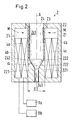
- Fig. 2 shows in a 1 analog representation of the permanent magnetic holding device 2 without the locking device 3.
- the permanent magnetic holding device 2 (see FIGS. 1 and 2) comprises a housing 22, the longitudinal axis of which is designated A.
- the Housing 22 is made of a ferromagnetic material.
- the Holding device 2 has a central passage 24 for receiving the Locking mechanism 3.
- the passage 24 extends in the direction of the Longitudinal axis A and has an upper cylindrical portion 241 to which is followed by a conical area 242, which then into a lower cylindrical portion 243 merges, the diameter of which is smaller than that Diameter of the upper cylindrical area 241.
- the conical area 242 and the lower cylindrical region 243 are formed by two extensions 221 of the housing 22 limits, each in the axial direction extend above, and their upper boundary surfaces 222 each obliquely to the longitudinal axis A, so that they the conical region 242 of Form passage 24.
- Half the cone angle is labeled ⁇ .
- a sleeve 23 is inserted, which consists of a non-ferromagnetic material, for example plastic.
- the housing 22 of the permanent magnetic holding device 2 are between the sleeve 23 and the outer wall of the housing two Permanent magnets 21 arranged, their magnetization, symbolically represented by the arrows M, perpendicular to the longitudinal axis A.
- the Permanent magnets 21 each have a cuboid shape and on both Sides located next to the central passage 24, or the Permanent magnets 21 are each designed as half-shells around the Passage 24 are arranged around.
- coils 4a, 4b are provided, which serve as actuating means, to the closing member 3 from its open position to its closed position move or vice versa.
- Each of the coils 4a, 4b surrounds the passage 24, the first coil 4a is internal with respect to the radial direction is arranged and the second coil 4b on the outside around the first coil 4a is arranged around.
- Each of the coils 4a, 4b can therefore, if they are powered is fed, directed in the direction of the longitudinal axis A. Apply electromagnetic force to the locking device 3.
- the in itself known control and supply devices 11a, 11b for the coils 4a, 4b are shown symbolically in FIG. 2.
- the closing member 3 (see FIG. 1) includes one in the sleeve 23 arranged rod 32, whose diameter D1 to the inner diameter the sleeve 23 in the upper cylindrical part 241 of the passage 24 adapted is so that the rod 32 is guided through the sleeve 23.
- the rod 32 is off made of a ferromagnetic material and tapers at its lower end conical, with half the cone angle preferably the same is as large as the angle ⁇ at which the boundary surfaces 222 are inclined are so that between the lower end of the rod 32 and the Boundary surfaces 222 there is an air gap 5 which is relative to the axial Direction is bounded by two mutually parallel surfaces that run obliquely with respect to the longitudinal axis A.
- the striker 31 is attached, here as a stamp with a handle 311 and a head 312 is formed.
- the stem 311 extends through through the lower conical region 243 of the passage 24 and ends on the head 312, which is arranged outside the housing 22 and for this purpose serves to disconnect the hose 10.
- the striker 31 is made of one made of non-ferromagnetic material.
- the upper end of the rod 32 protrudes from the housing 22 and is with a handle 33 provided as a mechanical actuator for the Closing member 3 is used.
- the handle 33 is on a thread 321 at the top screwed on the rod 32.
- a spring element 6 designed as a spiral spring provided which acts on the closing member 3 via the handle 33 and exerts a spring force on this, as shown above is directed.
- the bias of the spring element 6 and thus that of it caused spring force is adjustable by means of the handle 33.
- the handle 33 is on screwed further down the thread 321, the spring element 6 more compressed, which increases the spring force he exerts. If the handle 33 is screwed up on the thread 321, it is relaxed the spring element, resulting in a reduction in the closing organ 3 acting spring force results.
- the counterpart 8 has a support surface 81 for the hose 10 and is arranged so that the hose 10 between the Closing piece 31 of the locking member 3 and the counterpart 8 are clamped can be.
- the counterpart 8 is resilient with respect to the axial direction and adjustable to adapt to the diameter of the Allow hose 10 and to dampen the closing movement.
- the counterpart 8 is provided with a threaded bore 82, in which engages an adjusting screw 83, which is through a threadless Bore in the bracket 7 extends through.
- a spring 84 is provided between the bottom of the Counterpart 8 and the holder 7, so that the counterpart 8 is resiliently mounted with respect to the holder 7.
- the permanent magnetic holding device 2 can, as will be explained in more detail is explained, the closing member 3 in two different stable Maintain equilibrium positions, namely one shown in Fig. 1 Open position in which the hose 10 does not or only very little is clamped so that the liquid through the hose 10 can flow through, and a closed position in which the hose 10 between the closing piece 31 and the counterpart 8 is pinched that no more liquid through the hose 10 can flow through.
- Fig. 1 Open position in which the hose 10 does not or only very little is clamped so that the liquid through the hose 10 can flow through
- a closed position in which the hose 10 between the closing piece 31 and the counterpart 8 is pinched that no more liquid through the hose 10 can flow through.
- the striker 31 is without in FIG Contact with the hose 10 shown.
- Hose 10 is usually also slightly pinched in the open position between the closing piece 31 and the counterpart 8.
- An essential feature of the invention is that the permanent magnetic holding device 2, the closing element 3 in both Can maintain equilibrium positions (open position and closed position). While holding, the clamping device 1 does not require any energy in the form of electricity, which is why the clamping device 1 extremely economical with respect to Is energy consumption.
- the permanent magnetic flux PM flows from the north pole N of the permanent magnet through the sleeve 23 into the ferromagnetic rod 32, is axially downward from this guided, flows through the air gap 5 into the extension 221 of the housing 22, and is then from the housing 22 initially in the radial direction to the outside and then in the axial direction upwards to the south pole S of the Permanent magnets 21 returned.
- Fig. 1 Also shown in Fig. 1 are two field lines EM (solid Lines) of the electromagnetic flux from the coils 4a, 4b is generated, but is only available if the locking device from the Open to the closed position or from the closed position to the Open position is switched. These switching operations will be discussed later explained.
- EM solid Lines
- the path coordinate x increases to the right and the amount of each Force F upwards for positive forces and downwards for negative forces.
- the characteristic curve KS represents the hose force.
- the hose force With decreasing x the hose force initially takes approximately linear in the range d ⁇ x ⁇ a to. This area corresponds to the "collapse" of the hose, that is the tube is compressed more and more, causing the open Flow cross section reduced in it.
- the magnetic characteristic curve KM shows the dependence of the permanent magnetic force on the closing element 3 as a function of x again.
- the air gap 5 between the rod also becomes 32 and the extensions 221 of the housing 22 smaller, resulting in an increase of the permanent magnetic flux and thus that caused by it magnetic force on the closing member 3 results.
- the characteristic curve KS is representative of the sum of the Hose force and the spring force caused by the spring element 6 viewed.
- the characteristic curve KS thus represents the dependency of the Hose force from the path coordinate x, and for such preferred Refinements such as that described here, in which the spring element 6 is present, the characteristic curve KS represents the dependence of the sum from the hose force and the spring force from the path coordinate x. Since the Hose force has a path dependency in its linear range, which corresponds to that of a spring, so the hose is roughly like one Behaves in the spring, the sum of the hose force and the force caused by the spring element 6 for the sake of simplicity as Called spring force. This includes both the force of the "tube spring” as well as that of the spring element 6.
- the characteristic curve for the resulting total force which is based on the Closing member 3 acts, results from the addition of the magnetic KM characteristic curve and KS characteristic curve.
- the characteristic curve for the total force is in Fig. 3 with the reference number KR.
- the permanent magnetic holding device 2 is a bistable, passive retention system, being passive in the sense too understand is that the holding system no energy, z. B. in the form of electricity, must be fed to the locking organ in the open or in the To keep the closed position.
- the characteristic curve KS can be based on the material properties of the material which the hose 10 is made, and by the geometry of the Hose 10, for example the thickness of the hose wall, changed become. Furthermore, the characteristic curve KS can be selected by the choice of the spring element 6 can be varied, or via the bias of the spring element 6, by means of of the handle 33 (Fig. 1) is adjustable.
- the change or adaptation of the characteristic curve KM for those of the Magnetic force caused by permanent magnets 21 can take place via: Material, size, shape and strength of the permanent magnets 21, Material properties such as saturation magnetization and geometry of the components that carry the permanent magnetic flux, that is e.g. B. the rod 32, the extensions 221 and the housing 22 permanent magnetic force, for example, over the outside diameter Change D1 of the rod 32 (see Fig. 1) or over the extent D2 (see FIG. 2) of the extensions 221 in the radial direction.
- the course of the characteristic curve KM of the magnetic force over the angle ⁇ (Fig. 2) can be changed, which is the inclination of the Boundary surfaces 222 of the extensions 221 are determined.
- the closing element 3 consists of a stable one Equilibrium position is brought into the other stable equilibrium position.
- the locking device is in its Fig. 1 illustrated open position and in the closed position to be brought.
- the two coils 4a, 4b see Fig. 1, Fig. 2) Actuating means provided.
- the coils 4a, 4b arranged in such a way that they are activated when activated by Current on the closing member 3 in the direction of the closed position or electromagnetic force acting in the direction of the open position exercise.
- the direction of the electromagnetic force depends on the Polarity of the current that is fed into the coils 4a, 4b.
- FIG. 4 shows several force-displacement characteristics in an illustration analogous to FIG. 3.
- KS in turn designates the characteristic for the spring force, which results from the hose 10 and the spring element 6,
- KM denotes the Characteristic curve of the magnetic force exerted by the permanent magnets 21 and KR is the characteristic of the resulting total force.
- the coils 4a, 4b are now supplied with a positive current, so they cause an electromagnetic flow that is negative exerts electromagnetic force on the closing member 3.
- a positive Electricity has the electromagnetic flux and the permanent magnetic Flow in the same direction, that is, they add up in their effect.
- the total magnetic force i.e. the sum of the permanent magnetic force and the electromagnetic force proportional to the square of the sum of the electromagnetic and the permanent magnetic flux.
- This entire magnetic force, or their dependence on x is illustrated in FIG. 4 by the characteristic curve KE1, which is drawn with the symbols +.
- the symbol + should indicate that the current for the coils 4a, 4b has a positive sign.
- the Characteristic curve KG1 which represents the total force with positive current acts through the coils 4a, 4b on the closing element 3, results from Addition of the characteristic curves KS and KE1.
- This characteristic marked with KG1 is shown with the symbols ⁇ .
- x which are greater than f1
- KS spring force
- the coils 4a, 4b are acted upon by a negative current.
- the one generated by the activated coils 4a, 4b electromagnetic flow directed in the opposite direction permanent magnetic flux, that is, weaken these two rivers in their effect.
- the total magnetic force from the Permanent magnet 21 and the activated coils 4a, 4b on the Closing element 3 is exerted, is therefore for a negative current proportional to the square of the difference from the amount of permanent magnetic flux and the amount of electromagnetic River.
- the path dependence of this total magnetic force for the Case of a negative current in the coils 4a, 4b is in Fig. 4 by the Characteristic curve KE2 reproduced, which is shown with the symbols -.
- the Symbol - should indicate that the current for the coils 4a, 4b negative Has a sign.
- the positive or negative current can be set in a simple manner be that at least qualitatively the characteristic curves KE1 and KE2 result.
- the characteristic curve KE2 which is decisive for the opening becomes preferably set so that it is as close as possible below the x-axis runs. In practice, it is normally not possible to use the KE2 characteristic so that it lies exactly on the x-axis.
- the locking device can be opened Applying the coils 4a, 4b with a positive or with a negative current from the open to the closed position or from the closing position move the open position.
- the direction (the sign) and the amount of the current set so that for the locking device 3 there is only a stable equilibrium position (open or closed) as long as the current flows in the coils 4a, 4b.
- the clamping device 1 can also be operated mechanically in a simple manner be, for example if both coils 4a, 4b or the entire Power supply fail.
- the clamping device is actuated electromagnetically, one is Switching time of less than 100 milliseconds, e.g. around 80 Milliseconds, easy to implement.
- the switching time means the time which the closing element 3 needs to move out of one To move the equilibrium position to the other equilibrium position.
- Another advantageous measure is securing means to be provided, which are designed so that the distance between the Counterpart 8 and the locking piece 31 which interacts with it Closing device 3 is always larger than a minimum value.
- the measure can be taken especially during the closing process, in which the closing piece 31 moves down and the hose 10 against the Counterpart 8 presses, prevent the hose 10 from being damaged or is severed.
- the spring 84 dampens.
- the counterpart 8 has two projections 85, which are in the axial direction in each case by an amount 11 over the contact surface 81 for the hose 10 protrude.
- the head 312 'of the locking piece 31 of the locking element 3 comprises two disc-shaped elements 312a and 312b, which with respect to FIG Longitudinal axis A are arranged one above the other.
- the lower one, closer to Component 8 located element 312a has an axial height 12, with which its Extension in the direction of the longitudinal axis A is meant, which is smaller than that Amount 11 by which the projections 85 over the bearing surface 81 of the Project counterpart 8.
- the lower element is in the radial direction 312a dimensioned so that it fits between the two projections 85.
- the upper member 312b which is further away from the counterpart 8 on the other hand, dimensioned in the radial direction so that it is not between the Projections 85 fits.
- the counterpart 8 is as in the front explained resiliently with respect to the axial direction by means of spring 84 stored so that the closing or disconnecting of the hose 10 dampened.
- Fig. 6 shows, partly in section, a second embodiment of the Clamping device 1 according to the invention, which is particularly practical has proven.
- the principle of operation is identical to that of the first Embodiment and is therefore no longer explained. From the function hereby identical or equivalent parts are with the same, already explained reference numerals as in the first Embodiment, with a line in addition to the Reference numerals are used to refer to the different design point out. The following are the differences from the first Described embodiment, otherwise the explanations apply with respect to the first embodiment in a similar manner also for the second embodiment.
- this includes Closing member 3, which is shown in its open position in FIG. 6, two rod-shaped legs 32a, 32b and a cross bar 34 on which the Legs 32a, 32b are spaced apart and fastened parallel to each other.
- the both legs 32a, 32b each extend essentially perpendicular to the crossbar 34.
- the striker 31 ' is on the crossbar 34 between the two legs 32a, 32b arranged, but can also by Crossbar 34 itself can be realized.
- the permanent magnetic Holding device 2 comprises two permanent magnetic holders 2a, 2b, one of which is shown in section. Both holders 2a, 2b are the same configured and each take on one of the two legs 32a, 32b, that is, the leg 32a is held by the holder 2a and the Leg 32b through the holder 2b.
- the two have equilibrium positions (open and closed positions) Legs 32a, 32b and the permanent magnetic surrounding them Holder 2a, 2b the same function as the rod 32 and the permanent magnetic holding device 2 of the first embodiment.
- the striker 31 'on the Crossbar 34 is arranged with each permanent magnetic holder 2a, 2b instead of the passage 24 from FIG. 1, a recess 24 ' provided, each in the direction of the longitudinal axis A1 or A2 of the extends permanent magnetic holder 2a and 2b and with a conical region 242 'ends inside the housing 22'.
- This end will formed by the extension 221 'of the housing 22' which the two Corresponds to extensions 221 in FIG. 2. That arranged in the recess 24 '
- the ends of the legs 32a and 32b are each conical, in analogously the same way as for the rod 32 of the first Embodiment.
- a spring element 6 ' is provided to a upwards, i.e. in the direction of the open position, directed spring force on the Closing device 3 to exercise.
- a plate 322 is provided on part of each leg 32a, 32b which the spring element 6 'is supported. With its other end lies the spring element 6 'on the housing 22' or on the sleeve 23, which is fitted into the recess 24 '.
- the function of the spring elements 6 ' corresponds to that of the spring element 6 in FIG. 1.
- the spring elements 6 ' cause a spring force on the closing member 3, which of the Permanent magnet 21 counteracts the force.
- the bracket 7 for the counterpart 8 is between the two permanent magnetic holders 2a, 2b arranged so that the counterpart 8 with its support surface 81 is opposite the striker 31 '.
- the counterpart 8 is the same as in the first exemplary embodiment by means of the adjusting screw 83 with respect to the direction of the parallel Longitudinal axes A1, A2 adjustable and resilient in the spring 84 Bracket 7 stored.
- the legs 32a, 32b are each by means of pins 323a, 323b the cross bar 34 connected.
- the Crossbar 34 are pivoted upward about pin 323a, such as this is indicated by the arrow O, so that the hose 10 contacts the support surface 81 the counterpart 8 can be placed.
- the cross bar 34 pivoted down and the pin 323b inserted.
- the handle 33 'on the crossbar is used as a mechanical actuating means. appropriate.
- the closing element By exerting a downward force on the handle 33 ', for example by pressing by hand, the closing element can be removed from the Open position to be brought into the closed position.
- an upward force on the handle 33 ' for example by pulling by hand, the closing member 3 from the Closing position are brought into the open position.
- the hose 10 are also the second Embodiment on the counterpart 8, the two projections 85 provided, each in the axial direction by an amount 11 over the Protrude support surface 81 for the hose 10.
- the striker 31 ' protrudes downward by an amount 12 ⁇ 11 with respect to the axial direction the crossbar out and is in the perpendicular direction dimensioned so that it fits between the two projections 85.
- the minimal possible distance I1-I2 between the striker 31 'and the Contact surface 81 of counterpart 8 results when crossbar 34 is on the two projections 85 rests.
- FIG. 7 shows a schematic illustration of an exemplary embodiment of a fluid system for biological fluids, which comprises the combination of a pump device 100 for conveying a biological fluid with a clamping device 1 according to the invention.
- the fluid system is, for example, a heart-lung machine for maintaining blood circulation in a patient's body.
- the pump device 100 is a blood pump, the input of which is connected to the blood circulation of the patient, so that the blood can flow from the body to the blood pump 100, as indicated by the arrow E.
- the blood pump 100 conveys the blood in a tube 10 connected to its outlet Clamping device 1 according to the invention is provided, which can be designed according to the first or the second exemplary embodiment.
- the hose 10 is passed through the clamping device 1 and lies on the support surface 81 of the counterpart 8. Downstream of the clamping device 1, the tube 10 is connected to the patient's blood circulation, so that the delivered blood is supplied to the body circulation, as indicated by the arrow K.
- a bubble detector 101 Downstream of the output of the blood pump 100 and upstream of the Clamping device 1 is provided with a bubble detector 101, which monitors whether there are air bubbles in the blood flowing through the tube 10 are.
- the bubble detector is connected to the one or more via a signal line 102
- Control and supply device (s) 11a, 11b of the clamping device 1 connected.
- the control and supply devices 11a, 11b are over Lines 103 connected to the coils of the clamping device 1.
- the closing member 3 is Clamping device 1 in its open position, so that the delivered blood in can flow the patient’s body.
- the bubble detector detects one Air bubble in the hose 10, it transmits a signal to the control and Utilities 11 a, 11b, which then have a corresponding Feed current into the coils of the clamping device 1, so that Closing member 3 is moved into the closed position and the hose 10 clamped between the striker 31, 31 'and the support surface 81. Then the flow connection is broken and there is no more blood flow through the clamping device 1.
- the clamping device 1 can Close the flow connection for the blood before that of the Bubble detector 101 detected bubble has passed the clamping device 1. This will surely avoid getting the air bubble into the patient's body reached.
- the control and supply devices 11a, 11b by applying a corresponding current to the coils Clamping device 1 switch the closing device back to the open position.
- clamping device 1 Since the clamping device 1 according to the invention is only for switching Electricity is not required between the open position and the closed position but for keeping the locking device 3 in the stable
- the clamping device has equilibrium positions (open and closed position) 1 very low energy or electricity consumption and is therefore suitable especially for portable systems.
- the clamping device 1 can be very quickly and easily can be operated manually. By pressing the handle 33; 33 'or pulling on the handle 33; 33 ', the closing member 3 from the open to the Move the closed position or vice versa.
- the clamping device 1 also in the event of a power failure or an error in the Coils can be operated very quickly and reliably.
- clamping device 1 is also suitable for Fluid systems in which others prefer biological fluids or Fluids are transported as blood, e.g. B. infusion solutions or Nutrient solutions in bioreactors.
Abstract
Description
Die Erfindung betrifft eine Klemmvorrichtung zum Abklemmen eines
Schlauchs in einem Fluidsystem für biologische Flüssigkeiten, insbesondere
Blut, gemäss dem Oberbegriff des unabhängigen Anspruchs 1.The invention relates to a clamping device for clamping a
Hose in a fluid system for biological liquids, in particular
Blood, according to the preamble of
Fluidsysteme für biologische Flüssigkeiten umfassen typischerweise eine Pumpvorrichtung für das zu fördernde Fluid, welche über Schläuche mit einem Kreislauf bzw. mit anderen Elementen des Fluidsystems verbunden sind. Als Beispiel für eine solches Fluidsystem seien hier Herz-Lungen-Maschinen genannt, welche z. B. während einer Herzoperation mit dem Blutkreislauf des Patienten verbunden werden, um die Funktion des Herzens zu übernehmen und den Blutkreislauf aufrechtzuerhalten. Dabei ist es sehr wichtig, dass in dem Blut, welches in den Kreislauf des Patienten gefördert wird, möglichst keine Luftblasen vorhanden sind, weil diese ernsthafte Gefährdungen des Patienten darstellen. Daher ist in Herz-Lungen-Maschinen üblicherweise stromabwärts der Pumpe ein Blasendetektor und eine Klemmvorrichtung vorgesehen. Sobald der Blasendetektor eine Luftblase detektiert, muss die Klemmvorrichtung möglichst schnell den Schlauch, durch welchen das geförderte Blut in den Körper des Patienten strömt, abklemmen und damit die Blutversorgung zum Patienten unterbrechen, damit die Luftblase nicht in den Körperkreislauf vordringen kann. Die Klemmvorrichtung dient somit als Ein/Aus-Schalter für die Strömungsverbindung zwischen der Blutpumpe und dem Körperkreislauf des Patienten. Damit die Klemmvorrichtung die Strömungsverbindung genügend schnell durch Abklemmen des Schlauchs unterbrechen kann, ist es wünschenswert, dass ihre Schaltzeit weniger als 100 Millisekunden, vorzugsweise höchstens 80 Millisekunden beträgt.Fluid systems for biological fluids typically include one Pump device for the fluid to be pumped, which with hoses a circuit or connected to other elements of the fluid system are. Heart-lung machines are an example of such a fluid system called which z. B. during heart surgery with the The patient's bloodstream is linked to the function of the heart to take over and maintain blood circulation. It is very important that in the blood, which is promoted in the patient's circulation there will be no air bubbles because they are serious Represent risks to the patient. Hence in heart-lung machines usually a bubble detector and a downstream of the pump Clamping device provided. As soon as the bubble detector detects an air bubble detected, the clamping device must pass through the hose as quickly as possible clamped blood that flows into the patient’s body and thus interrupt the blood supply to the patient, so that the Air bubble cannot penetrate into the body's circulation. The clamping device thus serves as an on / off switch for the flow connection between the Blood pump and the patient's circulatory system. So that Clamping device through the flow connection quickly enough Disconnect the hose, it is desirable that their switching time is less than 100 milliseconds, preferably at most 80 Is milliseconds.
Es sind Klemmvorrichtungen bekannt, bei denen das Abklemmen mittels einer Spindel und einem die Spindel antreibenden Schrittmotor erfolgt. Diese Vorrichtungen haben jedoch den Nachteil, dass sie konstruktiv aufwendig sind und dass für eine ausreichende Schnelligkeit relativ grosse und leistungsstarke Schrittmotoren notwendig sind. Zudem sind solche Klemmvorrichtungen durch den Spindelantrieb bedingt selbsthemmend. Im Falle eines Ausfalls der Elektrik ist es daher - wenn überhaupt - nur sehr schwer möglich, die Klemmvorrichtung manuell zu öffnen oder zu schliessen.Clamping devices are known in which the clamping means a spindle and a stepper motor driving the spindle. This However, devices have the disadvantage that they are structurally complex are and that for a sufficient speed relatively large and powerful stepper motors are necessary. In addition, there are Clamping devices due to the spindle drive are self-locking. in the In the event of a failure of the electrical system, it is, if at all, only very much difficult to open or close the clamping device manually.
Ferner sind Klemmvorrichtungen bekannt, bei welchen das Schliessorgan, welches den blutführenden Schlauch abklemmt, elektromagnetisch betätigt wird. Das Schliessorgan wird mittels eines Elektromagneten, meist gegen die Kraft einer Feder, in die Schliessstellung bewegt und dort gehalten, oder umgekehrt, durch einen Elektromagneten gegen die Kraft einer Feder in der Offenstellung gehalten. Durch Deaktivieren des Elektromagneten bewegt sich dann das Schliessorgan aufgrund der Federkraft je nach konktreter Ausgestaltung in die Offenstellung oder in die Schliessstellung. Nachteilig an solchen Klemmvorichtungen ist ihr hoher Energieverbrauch, denn zumindest für einen Haltezustand, nämlich das Halten des Schliessorgans in der Offenstellung oder das Halten in der Schliessstellung wird ständig Energie benötigt, um den Elektromagneten mit Strom zu versorgen. Der ständige Stromfluss führt ferner zu einer nachteiligen Wärmeentwicklung. Der hohe Energiebedarf ist insbesondere bei tragbaren bzw. mobilen Systemen ein erheblicher Nachteil, weil solche Systeme üblicherweise mit Batterien gespeist werden. Auch im Hinblick auf Situationen, in denen die Herz-Lungen-Maschine nur mit Notstromversorgung betrieben werden kann, ist es wünschenswert, den Strombedaf möglichst gering zu halten. Zudem haben solche elektromagnetisch betriebenen Klemmvorrichtungen auch den Nachteil, dass sie beim Ausfall der Elektrik nicht manuell geöffnet oder geschlossen werden können.Clamping devices are also known in which the closing element, which disconnects the blood-carrying tube, operated electromagnetically becomes. The closing element is usually turned against the by means of an electromagnet Force of a spring, moved into the closed position and held there, or conversely, by an electromagnet against the force of a spring in the Open position held. Deactivating the electromagnet moves then the closing element due to the spring force depending on the conkreter Configuration in the open position or in the closed position. Disadvantageous such clamping devices is their high energy consumption, because at least for a holding state, namely holding the locking member in the Open position or holding in the closed position is constantly energy needed to power the electromagnet. The constant Current flow also leads to disadvantageous heat development. The height Energy requirements are particularly important for portable or mobile systems considerable disadvantage because such systems usually use batteries be fed. Also with regard to situations in which the heart-lung machine it can only be operated with an emergency power supply desirable to keep the electricity requirement as low as possible. Also have such electromagnetically operated clamping devices also Disadvantage that they do not open manually or in the event of electrical failure can be closed.
Ausgehend von diesem Stand der Technik ist es daher eine Aufgabe der Erfindung, eine Klemmvorrichtung zum Abklemmen eines Schlauches in einem Fluidsystem für biologische Flüssigkeiten vorzuschlagen, welche diese Nachteile nicht aufweist. Insbesondere soll die Klemmvorrichtung während des Betriebs möglichst wenig Energie (Strom) benötigen, konstruktiv einfach und möglichst kompakt sein. Sie soll ausreichend schnelle Schaltzeiten von weniger als etwa 100 Millisekunden ermöglichen, und zudem in einfacher Weise manuell betätigbar sein.Based on this prior art, it is therefore a task of Invention, a clamping device for clamping a hose in propose a fluid system for biological fluids, which these Does not have disadvantages. In particular, the clamping device should during use as little energy (electricity) as possible, structurally simple and be as compact as possible. It should have sufficiently fast switching times of enable less than about 100 milliseconds, and moreover in simpler Be manually operable.
Die diese Aufgaben lösende Klemmvorrichtung ist durch die Merkmale des
unabhängigen Anspruchs 1 gekennzeichnet.The clamping device solving these tasks is characterized by the features of
characterized
Erfindungsgemäss wird also eine Klemmvorrichtung zum Abklemmen eines Schlauchs in einem Fluidsystem für biologische Fluide, insbesondere Blut, vorgeschlagen, mit einem bewegbar angeordneten Schliessorgan, welches ein Schliessstück zum Abklemmen des Schlauches umfasst, mit einer permanentmagnetischen Halteeinrichtung, welche derart angeordnet und ausgestaltet ist, dass sie das Schliessorgan gegen eine Kraft in zwei verschiedenen stabilen Gleichgewichtslagen, nämlich einer Offenstellung und einer Schliessstellung, halten kann, ohne dass der permanentmagnetischen Halteeinrichtung für das Halten in der jeweiligen Gleichgewichtslage Energie zugeführt werden muss, sowie mit Betätigungsmitteln, um das Schliessorgan aus der Offenstellung in die Schliessstellung zu bewegen.According to the invention, a clamping device for clamping a Hose in a fluid system for biological fluids, in particular blood, proposed, with a movably arranged closing member, which includes a closing piece for clamping the hose, with a permanent magnetic holding device, which is arranged and is designed so that it closes the locking element against a force in two various stable equilibrium positions, namely an open position and a closed position, can hold without the permanent magnetic holding device for holding in the respective Equilibrium energy needs to be supplied, as well as with Actuating means to move the locking device from the open position into the To move the closing position.
Die permanentmagnetische Halteeinrichtung ist also derart ausgestaltet, dass für das Schliessorgan zwei stabile Gleichgewichtslagen existieren, nämlich zum einen die Offenstellung, in welcher ein in die Klemmvorrichtung eingelegter Schlauch nicht oder nur wenig geklemmt wird, sodass die Flüssigkeit durch den Schlauch hindurchströmen kann, und zum anderen eine Schliessstellung, in welcher der Schlauch durch das Schliessstück des Schliessorgans abgeklemmt wird, sodass keine Flüssigkeit mehr durch den Schlauch strömen kann. Zum Halten des Schliessorgans in den beiden Gleichgewichtslagen bedarf es keiner Energie in Form von Strom. Das Schliessorgan wird in den beiden Gleichgewichtslagen rein passiv, nämlich permanentmagnetisch, gehalten, was im Hinblick auf den Energieverbrauch ein ganz erheblicher Vorteil ist. The permanent magnetic holding device is thus designed such that there are two stable equilibrium positions for the locking device, namely on the one hand, the open position, in which one in the clamping device inserted hose is not or only slightly clamped, so that the Liquid can flow through the hose, and the other a closed position, in which the hose through the closing piece of the Closing member is clamped so that no more liquid through the Hose can flow. To hold the locking mechanism in the two Equilibrium positions do not require energy in the form of electricity. The Closing device becomes purely passive in the two equilibrium positions, namely permanent magnetic, held what in terms of energy consumption is a very significant advantage.
Zudem sind keine Spindelantriebe oder sonstige selbsthemmenden Antriebe zur Betätigung der Klemmvorrichtung notwendig, weshalb die Klemmvorrichtung konstruktiv einfach, sehr kompakt und insbesondere auch manuell betätigbar ist, das heisst manuell in die Offenstellung und in die Schliessstellung gebracht werden kann.In addition, there are no spindle drives or other self-locking drives necessary to operate the clamping device, which is why Clamping device structurally simple, very compact and in particular also is manually operable, that is, manually in the open position and in the Closing position can be brought.
Vorzugsweise umfassen die Betätigungsmittel mindestens eine Spule, welche so angeordnet ist, dass sie auf das Schliessorgan eine in Richtung auf die Schliessstellung oder in Richtung auf die Offenstellung wirkende elektomagnetische Kraft ausüben kann. Durch Aktivieren der Spule wird zusätzlich zur permanentmagnetischen Haltekraft eine elektromagnetische Kraft erzeugt, welche das Schliessorgan so weit aus seiner einen stabilen Gleichgewichtslage auslenkt, dass es seine andere stabile Gleichgewichtslage einnimmt. Die Spule braucht also nur aktiviert zu werden, falls das Schliessorgan aus der Offen- in die Schliessstellung gebracht werden soll oder umgekehrt aus der Schliess- in die Offenstellung.The actuating means preferably comprise at least one coil, which is arranged in such a way that it closes on the closing element in the direction of the Closing position or acting in the direction of the open position can exert electromagnetic force. By activating the coil in addition to the permanent magnetic holding force, an electromagnetic one Force which the locking organ so far out of its one stable Equilibrium position that it is its other stable Equilibrium. So the coil only needs to be activated, if the locking device is moved from the open to the closed position should be or vice versa from the closed to the open position.
Bei einem bevorzugten Ausführungsbeispiel umfasst das Schliessorgan zwei Schenkel sowie eine Querstange, wobei die Schenkel beabstandet zueinander mit der Querstange verbunden sind. Die permanentmagnetische Halteeinrichtung umfasst dann zwei permanentmagnetische Halter, von denen jeder jeweils einen Schenkel umgibt, und bei welcher das Schliessstück an der Querstange zwischen den beiden Schenkeln angeordnet ist. Vorzugsweise ist ferner für jeden Schenkel des Schliessorgans mindestens eine den Schenkel umgebende Spule zum Ausüben einer elektromagnetischen Kraft auf den Schenkel vorgesehen. Dieses Ausführungsbeispiel zeichnet sich durch sein besonders sicheres Betriebsverhalten aus.In a preferred embodiment, the closing member comprises two Leg and a crossbar, the legs spaced are connected to each other with the crossbar. The permanent magnetic Holding device then comprises two permanent magnetic holders, from each of which surrounds one leg, and where that Striker on the crossbar between the two legs is arranged. Preferably, for each leg of the Closing member for at least one coil surrounding the leg An electromagnetic force is exerted on the leg. This embodiment is particularly safe Operating behavior.
Vorzugsweise sind für das Schliessorgan oder für jeden Schenkel des Schliessorgans zwei separate Spulen als Betätigungsmittel vorgesehen, wobei für jede der beiden separaten Spulen jeweils eine getrennte Ansteuerund Versorgungsvorrichtung vorgesehen ist. Durch diese Massnahme lässt sich eine vorteilhafte Fehlertoleranz realisieren, welche die Betriebssicherheit erhöht. Falls nämlich eine der beiden separaten Spulen oder eine der beiden Ansteuer- und Versorgungsvorrichtungen aufgrund eines Fehlers ausfällt, beispielsweise durch den Bruch einer Leitung bzw. eines Kabels oder einen sonstigen Schaden, kann das Schliessorgan mit der noch fehlerfreien Spule weiterhin elektromagnetisch betätigt werden, sodass die Klemmvorrichtung vollständig funktionstüchtig bleibt.Preferably for the closing member or for each leg of the Closing device provided two separate coils as actuating means, where for each of the two separate coils a separate control and Supply device is provided. This measure leaves realize an advantageous fault tolerance, which increases operational safety elevated. If one of the two separate coils or one of the two Control and supply devices fail due to a fault, for example, by breaking a line or cable or a other damage, the locking device with the still faultless coil continue to be operated electromagnetically, so that the clamping device remains fully functional.
Eine weitere vorteilhafte Massnahme besteht darin, mindestens ein auf das Schliessorgan einwirkendes Federelement vorzusehen, welches so angeordnet ist, dass die Federkraft der magnetischen Kraft entgegenwirkt, welche die permanentmagnetische Haltevorrichtung auf das Schliessorgan ausübt. Durch diese Massnahme lässt sich die Klemmvorrichtung in einfacher Weise an die Eigenschaften des jeweils verwendeten Schlauchs anpassen.Another advantageous measure consists of at least one on the To provide closing element acting spring element, which so is arranged that the spring force counteracts the magnetic force, which the permanent magnetic holding device on the closing member exercises. This measure makes the clamping device easier Adapt to the properties of the hose used in each case.
Die erfindungsgemässe Klemmvorrichtung eignet sich insbesondere zur Kombination mit einer Pumpvorrichtung zum Fördern eines biologischen Fluids, speziell zur Kombination mit einer Blutpumpe, beispielsweise in einer Herz-Lungen-Maschine.The clamping device according to the invention is particularly suitable for Combination with a pumping device for pumping a biological Fluids, especially for combination with a blood pump, for example in a Life-support-machine.
Weitere vorteilhafte Massnahmen und bevorzugte Ausgestaltungen der Erfindung ergeben sich aus den abhängigen Ansprüchen.Further advantageous measures and preferred configurations of the Invention result from the dependent claims.
Im Folgenden wird die Erfindung anhand von Ausführungsbeispielen und anhand der Zeichnung näher erläutert. In der teilweise schematischen Zeichnung zeigen:
- Fig. 1:
- Einen Längsschnitt durch ein erstes Ausführungbeispiel der erfindungsgemässen Klemmvorrichtung,
- Fig.2:
- die permanentmagnetische Halteeinrichtung aus Fig. 1 (ohne Schliessorgan)
- Fig. 3:
- ein Diagramm mit Kraft-Weg-Kennlinien,
- Fig. 4:
- wie Fig. 3, jedoch inklusive Kennlinien für das Schalten in die Schliessstellung bzw. in die Offenstellung,
- Fig. 5:
- eine Ausführungsform von Sicherungsmitteln zum Vermeiden einer Beschädigung des Schlauchs,
- Fig. 6:
- ein zweites Ausführungsbeispiel der erfindungsgemässen Klemmvorrichtung, teilweise im Schnitt, und
- Fig. 7:
- eine schematische Darstellung eines Fluidsystems mit einer Kombination von einer Pumpvorrichtung mit einer erfindungsgemässen Klemmvorrichtung.
- Fig. 1:
- A longitudinal section through a first embodiment of the clamping device according to the invention,
- Fig. 2:
- the permanent magnetic holding device from Fig. 1 (without closing member)
- Fig. 3:
- a diagram with force-displacement characteristics,
- Fig. 4:
- 3, but including characteristics for switching to the closed position or to the open position,
- Fig. 5:
- an embodiment of securing means to avoid damage to the hose,
- Fig. 6:
- a second embodiment of the clamping device according to the invention, partly in section, and
- Fig. 7:
- is a schematic representation of a fluid system with a combination of a pump device with a clamping device according to the invention.
Bei der folgenden Beschreibung beziehen sich relative Lagebezeichnungen wie "oben", "unten", "oberhalb", "unterhalb" usw. auf die Darstellungen in den Figuren, haben jedoch keinen einschränkenden Charakter.In the following description, relative location designations refer such as "above", "below", "above", "below" etc. on the representations in the Figures, however, have no restrictive character.
Fig. 1 zeigt in einem Längsschnitt ein erstes Ausführungsbeispiel einer
erfindungsgemässen Klemmvorrichtung, die gesamthaft mit dem
Bezugszeichen 1 versehen ist. Die Klemmvorrichtung 1 umfasst ein
Schliessorgan 3 mit einem Schliessstück 31 zum Abklemmen eines
Schlauches 10 und eine permanentmagnetische Halteeinrichtung 2 zum
Halten des Schliessorgans 3 in zwei verschiedenen stabilen
Gleichgewichtslagen. Zum besseren Verständnis zeigt Fig. 2 in einer zu
Fig. 1 analogen Darstellung die permanentmagnetische Halteeinrichtung 2
ohne das Schliessorgan 3.Fig. 1 shows a first embodiment of a in a longitudinal section
Clamping device according to the invention, the total with the
Die permanentmagnetische Halteeinrichtung 2 (siehe Fig. 1 und Fig. 2)
umfasst ein Gehäuse 22, dessen Längsachse mit A bezeichnet ist. Das
Gehäuse 22 ist aus einem ferromagnetischen Material gefertigt. Die
Halteeinrichtung 2 weist einen zentralen Durchlass 24 zur Aufnahme des
Schliessorgans 3 auf. Der Durchlass 24 erstreckt sich in Richtung der
Längsachse A und weist ein oberen zylindrischen Bereich 241 auf, an den
sich ein konischer Bereich 242 anschliesst, der dann in einen unteren
zylindrischen Bereich 243 übergeht, dessen Durchmesser kleiner ist als der
Durchmesser des oberen zylindrischen Bereichs 241. Der konische Bereich
242 und der untere zylindrische Bereich 243 werden durch zwei Fortsätze
221 des Gehäuses 22 begrenzt, die sich jeweils in axialer Richtung nach
oben erstrecken, und deren oberen Begrenzungsflächen 222 jeweils schräg
zur Längsachse A verlaufen, sodass sie den konischen Bereich 242 des
Durchlasses 24 bilden. Der halbe Konuswinkel ist mit α bezeichnet. In den
oberen zylindrischen Bereich 241 ist eine Hülse 23 eingesetzt, die aus einem
nicht-ferromagnetischen Material, beispielsweise Kunststoff hergestellt ist.The permanent magnetic holding device 2 (see FIGS. 1 and 2)
comprises a
In dem Gehäuse 22 der permanentmagnetischen Halteeinrichtung 2 sind
zwischen der Hülse 23 und der äusseren Wandung des Gehäuses zwei
Permanentmagnete 21 angeordnet, deren Magnetisierung, symbolisch
dargestellt durch die Pfeile M, senkrecht zur Längsachse A liegt. In dem hier
beschriebenen Ausführungsbeispiel liegt jeweils der Nordpol N innen und der
Südpol S aussen, das heisst die Magnetisierung M weist jeweils von aussen
nach innen, also zur Längsachse A hin gerichtet. Beispielsweise sind die
Permanentmagnete 21 jeweils quaderförmig ausgestaltet und auf beiden
Seiten neben dem zentralen Durchlass 24 angeordnet, oder die
Permanentmagnete 21 sind jeweils als Halbschalen ausgestaltet, die um den
Durchlass 24 herum angeordnet sind.In the
Unterhalb der Permanentmagnete 21 sind in dem Gehäuse 22 zwei koaxial
angeordnete Spulen 4a,4b vorgesehen, welche als Betätigungsmittel dienen,
um das Schliessorgan 3 aus seiner Offenstellung in seine Schliessstellung zu
bewegen bzw. umgekehrt. Jede der Spulen 4a,4b umgibt den Durchlass 24,
wobei die erste Spule 4a bezüglich der radialen Richtung innenliegend
angeordnet ist und die zweite Spule 4b aussenliegend um die erste Spule 4a
herum angeordnet ist. Jede der Spulen 4a,4b kann also, wenn sie mit Strom
gespeist wird, eine in Richtung der Längsachse A gerichtete
elektromagnetische Kraft auf das Schliessorgan 3 ausüben. Die an sich
bekannten Ansteuer- und Versorgungseinrichtungen 11a, 11b für die Spulen
4a,4b sind in Fig. 2 symbolisch dargestellt. Natürlich sind auch
Ausgestaltungen mit nur einer Spule als Betätigungsmittel für das
Schliessorgan 3 möglich. Mit zwei separaten Spulen 4a, 4b lässt sich jedoch
eine vorteilhafte Fehlertoleranz realisieren, da im Falle eines Fehlers in einer
Spule das Schliessorgan 3 noch mittels der anderen Spule betätigt werden
kann. Daher sind vorzugsweise auch getrennte Ansteuer- und
Versorgungsvorrichtungen 11a, 11b mit getrennten Verstärkern für die beiden
Spulen 4a,4b vorgesehen. Below the
Das Schliessorgan 3 (siehe Fig. 1) umfasst einen in der Hülse 23
angeordneten Stab 32, dessen Durchmesser D1 an den Innendurchmesser
der Hülse 23 im oberen zylindrischen Teil 241 des Durchlasses 24 angepasst
ist, sodass der Stab 32 durch die Hülse 23 geführt ist. Der Stab 32 ist aus
einem ferromagnetischen Material gefertigt und verjüngt sich an seinem
unteren Ende konisch, wobei der halbe Konuswinkel vorzugsweise gleich
gross ist wie der Winkel α, unter dem die Begrenzungsflächen 222 geneigt
sind, sodass zwischen dem unteren Ende des Stabs 32 und den
Begrenzungsflächen 222 ein Luftspalt 5 existiert, der bezüglich der axialen
Richtung von zwei zueinander parallelen Flächen begrenzt wird, die
bezüglich der Längsachse A schräg verlaufen. Am unteren Ende des Stabs
32 ist das Schliessstück 31 befestigt, das hier als Stempel mit einem Stiel
311 und einem Kopf 312 ausgebildet ist. Der Stiel 311 erstreckt sich durch
den unteren konischen Bereich 243 des Durchlasses 24 hindurch und endet
an dem Kopf 312, der ausserhalb des Gehäuses 22 angeordnet ist und dazu
dient, den Schlauch 10 abzuklemmen. Das Schliessstück 31 ist aus einem
nicht-ferromagnetischen Material hergestellt.The closing member 3 (see FIG. 1) includes one in the
Das obere Ende des Stabs 32 ragt aus dem Gehäuse 22 heraus und ist mit
einem Griff 33 versehen, der als mechanisches Betätigungsmittel für das
Schliessorgan 3 dient. Der Griff 33 ist auf ein Gewinde 321 am oberen Ende
des Stabs 32 aufgeschraubt. Zwischen dem Griff 33 und dem Gehäuse 22
bzw. der Hülse 23 ist ein als Spiralfeder ausgestaltetes Federelement 6
vorgesehen, welches über den Griff 33 auf das Schliessorgan 3 einwirkt und
auf dieses eine Federkraft ausübt, die darstellungsgemäss nach oben
gerichtet ist. Die Vorspannung des Federelements 6 und damit die von ihm
bewirkte Federkraft ist mittels des Griffs 33 einstellbar. Wird der Griff 33 auf
dem Gewinde 321 weiter nach unten geschraubt, so wird das Federelement 6
stärker komprimiert, wodurch sich die von ihm ausgeübte Federkraft erhöht.
Wird der Griff 33 auf dem Gewinde 321 nach oben geschraubt, so entspannt
sich das Federelement, woraus eine Reduzierung der auf das Schliessorgan
3 einwirkenden Federkraft resultiert.The upper end of the
Unterhalb des Gehäuses 22 ist eine an dem Gehäuse 22 befestigte
Halterung 7 für ein Gegenstück 8 zum Auflegen des Schlauchs 10
vorgesehen. Das Gegenstück 8 weist eine Auflagefläche 81 für den Schlauch
10 auf und ist so angeordnet, dass der Schlauch 10 zwischen dem
Schliessstück 31 des Schliessorgans 3 und dem Gegenstück 8 eingeklemmt
werden kann. Das Gegenstück 8 ist bezüglich der axialen Richtung federnd
und verstellbar gelagert, um eine Anpassung an den Durchmesser des
Schlauchs 10 zu ermöglichen und um die Schliessbewegung zu dämpfen.
Dazu ist das Gegenstück 8 mit einer Gewindebohrung 82 versehen, in
welche eine Justierschraube 83 eingreift, die sich durch eine gewindelose
Bohrung in der Halterung 7 hindurch erstreckt. Zwischen der Unterseite des
Gegenstücks 8 und der Halterung 7 ist eine Feder 84 vorgesehen, sodass
das Gegenstück 8 bezüglich der Halterung 7 federnd gelagert ist. Durch
Drehen der Justierschraube 83 kann das Gegenstück 8 in Richtung der
Längsachse A nach oben bzw. nach unten verschoben werden, wodurch die
Klemmvorrichtung 1 an den Durchmesser des jeweils verwendeten Schlauchs
10 angepasst werden kann.Below the
Die permanentmagnetische Halteeinrichtung 2 kann, wie noch eingehender
erläutert wird, das Schliessorgan 3 in zwei verschiedenen stabilen
Gleichgewichtlagen halten, nämlich einer in Fig. 1 dargestellten
Offenstellung, in welcher der Schlauch 10 nicht oder nur sehr wenig
geklemmt wird, sodass die Flüssigkeit durch den Schlauch 10
hindurchströmen kann, und einer Schliessstellung, in welcher der Schlauch
10 derart zwischen dem Schliessstück 31 und dem Gegenstück 8
eingeklemmt wird, dass keine Flüssigkeit mehr durch den Schlauch 10
hindurchströmen kann. In der Offenstellung (Fig. 1) ist der
Strömungsquerschnitt für die Flüssigkeit im Schlauch 10 maximal. Zum
Schliessen wird das Schliessorgan 3 in noch zu erläuternder Weise nach
unten bewegt und presst dadurch den Schlauch 10 derart zusammen, das
der Strömungsquerschnitt Null wird. In dieser Schliessstellung des
Schliessorgans 3 ist der Schlauch 10 dann abgeklemmt.The permanent
Aus Gründen der besseren Übersicht ist in Fig. 1 das Schliessstück 31 ohne
Kontakt mit dem Schlauch 10 dargestellt. In der Praxis ist jedoch der
Schlauch 10 üblicherweise auch in der Offenstellung leicht eingeklemmt
zwischen dem Schliessstück 31 und dem Gegenstück 8. For the sake of a better overview, the
Ein wesentliches Merkmal der Erfindung ist es, dass die
permanentmagnetische Halteeinrichtung 2 das Schliessorgan 3 in beiden
Gleichgewichtslagen (Offenstellung und Schliessstellung) halten kann.
Während des Haltens benötigt die Klemmvorrichtung 1 keine Energie in Form
von Strom, weshalb die Klemmvorrichtung 1 enorm sparsam bezüglich des
Energieverbrauchs ist.An essential feature of the invention is that the
permanent
In Fig. 1 ist der von den Permanentmagneten 21 generierte
permanentmagnetische Fluss durch die beiden gestrichelt gezeichneten
Feldlinien PM symbolisch dargestellt. Der permanentmagnetische Fluss PM
fliesst vom Nordpol N des Permanentmagneten durch die Hülse 23 in den
ferromagnetischen Stab 32, wird von diesem in axialer Richtung nach unten
geführt, fliesst durch den Luftspalt 5 in den Fortsatz 221 des Gehäuses 22,
und wird dann vom Gehäuse 22 zunächst in radialer Richtung nach aussen
und dann in axialer Richtung nach oben zum Südpol S des
Permanentmagneten 21 zurückgeführt.1 is that generated by the
Ebenfalls eingezeichnet in Fig. 1 sind zwei Feldlinien EM (durchgezogene
Linien) des elektromagnetischen Flusses, der von den Spulen 4a,4b
generiert wird, aber nur vorhanden ist, wenn das Schliessorgan aus der
Offen- in die Schliessstellung oder aus der Schliessstellung in die
Offenstellung geschaltet wird. Diese Schaltvorgänge werden weiter hinten
erläutert.Also shown in Fig. 1 are two field lines EM (solid
Lines) of the electromagnetic flux from the
Im Folgenden wird nun das Halten des Schliessorgans 3 in den beiden
Gleichgewichtslagen anhand von Fig. 3 näher erläutert. Ohne Beschränkung
der Allgemeinheit werden Kräfte, die nach unten wirken, also in Richtung auf
die Schliessstellung, als negativ dargestellt und bezeichnet, und Kräfte die
nach oben wirken als positiv. Während des Haltens in der Offen- oder der
Schliessstellung sind die Spulen 4a,4b deaktiviert, sodass sie keine
elektromagnetische Kraft auf das Schliessorgan 3 ausüben. Dann wirken auf
das Schliessorgan 3 im wesentlichen die folgenden Kräfte: Die negative
magnetische Kraft, welche von den Permanentmagneten 21 ausgeübt wird,
eine positive Kraft, welche der Schlauch 10 bewirkt und welche im Folgenden
als Schlauchkraft bezeichnet wird, sowie die positive Federkraft, welche das
Federelement 6 bewirkt. Der Betrag dieser Kräfte ist von einer
Wegkoordinate x abhängig. Die Wegkoordinate x (siehe Fig. 1) gibt den
Abstand zwischen der Auflagefläche 81 des Gegenstücks 8 und der ihr
zugewandten Begrenzungsfläche des Kopfs 312 des Schliessstücks 31 an,
wobei x=0 bedeutet, dass der Kopf 312 des Schliessstücks 31 auf der
Auflagefläche 81 des Gegenstücks 8 aufliegt.In the following, the
In Fig. 3 sind verschiedenen Kraft-Weg-Kennlinien für den Fall aufgetragen,
dass die Spulen 4a, 4b deaktiviert sind, also nicht mit Strom gespeist werden.
Die Wegkoordinate x nimmt nach rechts zu und der Betrag der jeweiligen
Kraft F nach oben für positive Kräfte und nach unten für negative Kräfte.3 shows various force-displacement characteristics for the case
that the
Die Kennlinie KS repräsentiert die Schlauchkraft. Für x=a (oder x>a) ist der Schlauch ganz offen, die Schlauchkraft ist Null. Mit kleiner werdendem x nimmt die Schlauchkraft im Bereich d<x<a zunächst näherungsweise linear zu. Dieser Bereich entspricht dem "Kollabieren" des Schlauchs, das heisst der Schlauch wird immer mehr zusammengedrückt, wodurch sich der offene Strömungsquerschnitt in ihm reduziert. Bei x=d ist der Schlauch vollständig "kollabiert", das heisst er ist so eingeklemmt, dass der offene Strömungsquerschnitt in ihm Null ist. Bei weiterer Reduzierung von x (f<x<d) wird die Schlauchwand komprimiert, was zu einem sehr steilen Anstieg in der Schlauchkraft führt.The characteristic curve KS represents the hose force. For x = a (or x> a) it is Hose completely open, the hose force is zero. With decreasing x the hose force initially takes approximately linear in the range d <x <a to. This area corresponds to the "collapse" of the hose, that is the tube is compressed more and more, causing the open Flow cross section reduced in it. At x = d the hose is complete "collapses", that is, it is so pinched that the open Flow cross section in it is zero. If x (f <x <d) is further reduced the hose wall is compressed, resulting in a very steep increase in the Hose force leads.
Die magnetische Kennlinie KM gibt die Abhängigkeit der
permanentmagnetischen Kraft auf das Schliessorgan 3 in Abhängigkeit von x
wieder. Mit kleiner werdendem x wird auch der Luftspalt 5 zwischen dem Stab
32 und den Fortsätzen 221 des Gehäuses 22 kleiner, woraus eine Erhöhung
des permanentmagnetischen Flusses und damit der von ihm bewirkten
magnetischen Kraft auf das Schliessorgan 3 resultiert. Vorzugsweise ist der
Spalt 5 so bemessen, dass er für x=0 gerade ganz geschlossen ist. Da die
magnetische Kraft im wesentlich proportional zum Quadrat des magnetischen
Flusses ist, steigt der Betrag der magnetischen Kraft mit kleiner werdendem x
im wesentlichen quadratisch an. Diese Abhängigkeit führt qualitativ zu der in
Fig. 3 dargestellten Kennlinie KM.The magnetic characteristic curve KM shows the dependence of the
permanent magnetic force on the
Für die positive Federkraft, welche das Federelement 6 bewirkt, ist in Fig. 3
keine gesonderte Kennlinie eingezeichnet. Die Federkraft hängt im
wesentlichen linear vom Weg x ab, wobei der Betrag der Federkraft mit
kleiner werdendem x grösser wird. Rein qualitativ verläuft die Kennlinie für
die Federkraft also in gleicher Weise wie die Kennlinie KS der Schlauchkraft
in ihrem linearen Bereich (d<x<a). Da es für das Verständnis ausreichend ist,
wird die Kennlinie KS im Folgenden als repräsentativ für die Summe aus der
Schlauchkraft und der von dem Federelement 6 bewirkten Federkraft
angesehen. Für solche Ausgestaltungen, bei denen kein Federelement 6
vorgesehen ist, repräsentiert die Kennlinie KS also die Abhängigkeit der
Schlauchkraft von der Wegkoordinate x, und für solche bevorzugten
Ausgestaltungen wie der hier beschriebenen, bei denen das Federelement 6
vorhanden ist, repräsentiert die Kennlinie KS die Abhängigkeit der Summe
aus der Schlauchkraft und der Federkraft von der Wegkoordinate x. Da die
Schlauchkraft in ihrem linearen Bereich eine Wegabhängigkeit aufweist,
welche der einer Feder entspricht, der Schlauch sich also etwa wie eine
Feder verhält, wird im Folgenden die Summe aus der Schlauchkraft und der
von dem Federelement 6 bewirkten Kraft der Einfachheit halber als
Federkraft bezeichnet. Diese beinhaltet sowohl die Kraft der "Schlauchfeder"
als auch die des Federelements 6.3 for the positive spring force which the
Die Kennlinie für die resultierende Gesamtkraft, welche auf das
Schliessorgan 3 einwirkt, ergibt sich durch Addition der magnetischen
Kennlinie KM und der Kennlinie KS. Die Kennlinie für die Gesamtkraft ist in
Fig. 3 mit dem Bezugszeichen KR bezeichnet. Wie dies Fig. 3 zeigt, hat die
Kennlinie KR drei Nulldurchgänge, nämlich bei den Werten x=b, x=f und x=c.
Bei diesen Nulldurchgängen ist die resultierende Gesamtkraft auf das
Schliessorgan 31 Null, das heisst für diese drei Werte b, f, c befindet sich
das Schliessorgan im Kräftegleichgewicht. Zwei der Gleichgewichtslagen,
nämlich x=f und x=b, sind stabile Gleichgewichtslagen. Befindet sich
beispielsweise das Schliessorgan 3 in der Position x=f und wird es in
Richtung kleiner werdender x-Koordinate aus dieser Lage ausgelenkt, so
überwiegt die positive Federkraft und bewirkt wieder eine Vergrösserung von
x, das heisst, das Schliessorgan 3 kehrt in die Gleichgewichtslage x=f zurück.
Lenkt man das Schliessorgan 3 aus der Gleichgewichtslage x=f in Richtung
grösser werdender x-Koordinate aus, so überwiegt die negative magnetische
Kraft und zieht das Schliessorgan 3 in die Gleichgewichtslage x=f zurück.
Folglich ist x=f eine stabile Gleichgewichtslage. In analoger Weise ergibt
sich, dass auch der Wert x=b einer stabilen Gleichgewichtslage des
Schliessorgans 3 entspricht. Die stabile Gleichgewichtslage x=f ist die
Schliessstellung des Schliessorgans 3 und die stabile Gleichgewichtslage
x=b seine Offenstellung.The characteristic curve for the resulting total force, which is based on the
Die dritte Gleichgewichtslage bei x=c ist eine labile Gleichgewichtslage.
Befindet sich das Schliessorgan 3 in der Position x=c und lenkt man es nur
geringfügig in Richtung grösser werdender x-Koordinate aus dieser
Gleichgewichtslage aus, so überwiegt die Federkraft, wodurch x noch weiter
vergrössert wird, bis das Schliessorgan 3 bei x=b eine stabile
Gleichgewichtslage (Offenstellung) einnimmt. Lenkt man das Schliessorgan 3
aus der Position x=c in Richtung kleiner werdender x-Koordinate aus, so
überwiegt die negative magnetische Kraft, wodurch x noch weiter verkleinert
wird, bis das Schliessorgan bei x=f die andere stabile Gleichgewichtslage
(Schliessstellung) einnimmt.The third equilibrium position at x = c is an unstable equilibrium position.
If the
Somit existieren genau zwei stabile Gleichgewichtslagen, nämlich die
Offenstellung und die Schliessstellung des Schliessorgans 3, in denen sich
die von den Permanentmagneten 21 auf das Schliessorgan 3 ausgeübte
Kraft und die auf das Schliessorgan 3 einwirkende Federkraft gegenseitig
dauerhaft kompensieren. Die permanentmagnetische Halteeinrichtung 2 ist
ein bistabiles, passives Haltesystem, wobei passiv in dem Sinne zu
verstehen ist, dass dem Haltesystem keine Energie, z. B. in Form von Strom,
zugeführt werden muss, um das Schliessorgan in der Offen- oder in der
Schliessstellung zu halten.So there are exactly two stable equilibrium positions, namely the
Open position and the closed position of the
Um die beiden Kennlinien KM und KS so aufeinander abzustimmen, dass sich die gewünschte resultierende Kennlinie KS ergibt, stehen verschiedene Massnahmen zur Verfügung, von denen hier nur einige in nicht abschliessender Aufzählung erwähnt werden.To coordinate the two characteristic curves KM and KS so that If the desired resulting characteristic curve KS results, there are different ones Measures are available, some of which are not in here final list should be mentioned.
Die Kennlinie KS kann über die Materialeigenschaften des Materials, aus
welchem der Schlauch 10 hergestellt ist, sowie durch die Geometrie des
Schlauchs 10, beispielsweise die Dicke der Schlauchwand, verändert
werden. Ferner kann die Kennlinie KS durch die Wahl des Federelements 6
variiert werden, oder über die Vorspannung des Federelements 6, die mittels
des Griffs 33 (Fig. 1) einstellbar ist.The characteristic curve KS can be based on the material properties of the material
which the
Die Änderung bzw. Anpassung der Kennlinie KM für die von den
Permanentmagneten 21 verursachte magnetische Kraft kann erfolgen über:
Material, Grösse, Form und Stärke der Permanentmagneten 21,
Materialeigenschaften wie die Sättigungsmagnetisierung, sowie Geometrie
derjenigen Bauteile, welche den permanentmagnetischen Fluss führen, also
z. B. der Stab 32, die Fortsätze 221 und das Gehäuse 22. So lässt sich die
permanentmagnetische Kraft beispielsweise über den Aussendurchmesser
D1 des Stabs 32 (siehe Fig. 1) verändern oder über die Ausdehnung D2
(siehe Fig. 2) der Fortsätze 221 in radialer Richtung.The change or adaptation of the characteristic curve KM for those of the
Magnetic force caused by
Insbesondere kann der Verlauf der Kennlinie KM der magnetischen Kraft
über den Winkel α (Fig. 2) geändert werden, welcher die Neigung der
Begrenzungsflächen 222 der Fortsätze 221 bestimmt. Aus
fertigungstechnischen Gründen wird α vorzugsweise zwischen 0° und 90°
gewählt. Kleine Werte von α haben zur Folge, dass die magnetische
Kennlinie KM flacher, also mit geringerer Steigung insbesondere für kleine
Werte von x, verläuft, während grössere Werte von α die magnetische
Kennlinie KM steiler werden lassen. Für α = 90° verlaufen die
Begrenzungsflächen 222 senkrecht zur Längsachse A, das heisst der
konische Bereich 242 des Durchlasses 24 (Fig. 2) ist nicht vorhanden.In particular, the course of the characteristic curve KM of the magnetic force
over the angle α (Fig. 2) can be changed, which is the inclination of the
Boundary surfaces 222 of the
Durch diese Massnahmen ist es möglich, die beiden Kennlininen, nämlich die
Kennlinie KM für die magnetische Kraft und die Kennlinie KS für die Summe
aus der von dem Schlauch 10 und von dem Federelment 6 verursachten
Federkraft, so aufeinander abzustimmen, dass für das Schliessorgan 3 zwei
stabile Gleichgewichtslagen existieren, wenn kein Strom in die Spulen 4a,4b
eingespeist wird.These measures make it possible to measure the two characteristics, namely the
Characteristic curve KM for the magnetic force and characteristic curve KS for the sum
from that caused by the
Es wird nun erläutert, wie das Schliessorgan 3 aus einer stabilen
Gleichgewichtslage in die andere stabile Gleichgewichtslage gebracht wird.
Zunächst wird davon ausgegangen, dass sich das Schliessorgan in seiner in
Fig. 1 veranschaulichten Offenstellung befindet und in die Schliessstellung
gebracht werden soll. Dazu sind bei dem hier beschriebenen
Ausführungsbeispiel die beiden Spulen 4a,4b (siehe Fig 1, Fig. 2) als
Betätigungsmittel vorgesehen. Wie bereits erläutert, sind die Spulen 4a, 4b
so angeordnet, dass sie bei ihrer Aktivierung durch Beaufschlagung mit
Strom auf das Schliessorgan 3 eine in Richtung auf die Schliessstellung oder
in Richtung auf die Offenstellung wirkende elektromagnetische Kraft
ausüben. Die Richtung der elektromagnetischen Kraft hängt dabei von der
Polarität des Stromes ab, der in die Spulen 4a,4b eingespeist wird. Ohne
Beschränkung der Allgemeinheit sei vereinbart, dass ein Strom mit positivem
Vorzeichen eine in Richtung der Längsachse A nach unten - also auf die
Schliessstellung hin - gerichtete elektromagnetische Kraft auf das
Schliessorgan 3 bewirkt und ein Strom mit negativem Vorzeichen eine in
Richtung der Längsachse A nach oben gerichte elektomagnetische Kraft. In
Fig. 1 ist der elektromagnetische Fluss, der aus einem positiven Strom
resultiert, symbolisch durch die beiden Feldlinien EM veranschaulicht.It will now be explained how the
Fig. 4 zeigt in einer zu Fig. 3 analogen Darstellung mehrere Kraft-Weg-Kennlinien.
KS bezeichnet wiederum die Kennlinie für die Federkraft, welche
aus dem Schlauch 10 und dem Federelement 6 resultiert, KM bezeichnet die
Kennlinie der magnetischen Kraft, die von den Permanentmagneten 21
verursacht wird und KR die Kennlinie der resultierenden Gesamtkraft. Die
Kennlinien KM, KR beziehen sich auf den Fall, dass die Spulen 4a,4b nicht
mit Strom beaufschlagt werden. In diesem Fall existieren für das
Schliessorgan 3 die beiden stabilenen Gleichgewichtslagen bei x=b
(Offenstellung) und x=f (Schliessstellung).FIG. 4 shows several force-displacement characteristics in an illustration analogous to FIG. 3.
KS in turn designates the characteristic for the spring force, which
results from the
Werden nun die Spulen 4a,4b mit einem positiven Strom beaufschlagt, so
verursachen sie einen elektromagnetischen Fluss, der eine negative
elektromagnetische Kraft auf das Schliessorgan 3 ausübt. Für einen positiven
Strom haben der elektromagnetische Fluss und der permanentmagnetische
Fluss die gleiche Richtung, das heisst sie addieren sich in ihrer Wirkung. Die
gesamte magnetische Kraft, also die Summe aus der
permanentmagnetischen Kraft und der elektromagnetischen Kraft, ist
proportional zum Quadrat der Summe aus dem elektromagnetischen und
dem permanentmagnetischen Fluss. Diese gesamte magnetische Kraft, bzw.
ihre Abhängigkeit von x, ist in Fig. 4 durch die Kennlinie KE1 veranschaulicht,
welche mit den Symbolen + eingezeichnet ist. Das Symbol + soll dabei
anzeigen, dass der Strom für die Spulen 4a,4b positives Vorzeichen hat. Die
Kennlinie KG1, welche die Gesamtkraft repräsentiert, die bei positivem Strom
durch die Spulen 4a,4b auf das Schliessorgan 3 einwirkt, ergibt sich durch
Addition der Kennlinien KS und KE1. Diese mit KG1 bezeichnete Kennlinie
ist mit den Symbolen ⊕ dargestellt. Wie dies Fig. 4 zeigt, weist die Kennlinie
KG1 nur noch einen Nulldurchgang bei x=f1 auf, wobei f1<f ist. Dieser
Nulldurchgang bei f1 ist eine stabile Gleichgewichtslage. Für alle Werte von
x, die grösser als f1 sind, ist die gesamte magnetische Kraft (Kennlinie KE1)
betragsmässig stets grösser als die Federkraft (Kennlinie KS), sodass die
resultierende Gesamtkraft (Kennlinie KG1) stets negativ ist. Befindet sich
also das Schliessorgan anfänglich in seiner Offenstellung (x=b) und wird
dann ein positiver Strom in die Spulen 4a,4b eingespeist, so bewegt sich das
Schliessorgan in die Gleichgewichtslage f1. Nach Abschalten des Stroms
durch die Spulen 4a,4b nimmt das Schliessorgan 3 die stabile
Gleichgewichtslage x=f auf der Kennlinie KR ein und befindet sich somit in
seiner Schliessstellung. Der Schlauch 10 ist abgeklemmt, das heisst er ist
derart zwischen dem Schliessstück 31 und dem Gegenstück 8 eingeklemmt,
dass keine Flüssigkeit mehr durch ihn hindurchströmen kann.If the
Um das Schliessorgan 3 aus der Offen- in die Schliessstellung zu bewegen,
ist es nicht notwendig, den positiven Strom solange eingeschaltet zu lassen,
bis das Schliessorgan 3 die Gleichgewichtslage bei x=f1 angenommen hat.
Der Strom durch die Spulen 4a,4b kann bereits abgeschaltet werden, sobald
sich das Schliessorgan 3 bei einer Wegkoordinate x befindet, die kleiner ist
als c. Auf der Kennlinie KR, die den stromlosen Fall repräsentiert, befindet
man sich dann nämlich bereits links der labilen Gleichgewichtslage x=c,
sodass das Schliessorgan 3 selbsttätig, das heisst ohne Unterstützung durch
die elektromagnetische Kraft bzw. den elektromagnetischen Fluss, seine
stabile Gleichgewichtslage bei x=f (Schliessstellung) einnimmt.To move the
Um das Schliessorgan 3 aus der Schliessstellung in die Offenstellung zu
bewegen, werden die Spulen 4a,4b mit einem negativen Strom beaufschlagt.
In diesem Fall ist der von den aktivierten Spulen 4a,4b generierte
elektromagnetische Fluss entgegengesetzt gerichtet zum
permanentmagnetischen Fluss, das heisst diese beiden Flüsse schwächen
sich in ihrer Wirkung ab. Die gesamte magnetische Kraft, die von den
Permanentmagneten 21 und den aktivierten Spulen 4a,4b auf das
Schliessorgan 3 ausgeübt wird, ist also für einen negativen Strom
proportional zum Quadrat der Differenz aus dem Betrag des
permanentmagnetischen Flusses und dem Betrag des elektromagnetischen
Flusses. Die Wegabhängigkeit dieser gesamten magnetischen Kraft für den
Fall eines negativen Stroms in den Spulen 4a,4b ist in Fig. 4 durch die
Kennlinie KE2 wiedergegeben, die mit den Symbolen - dargestellt ist. Das
Symbol - soll dabei anzeigen, dass der Strom für die Spulen 4a,4b negatives
Vorzeichen hat. Die Kennlinie KG2, welche die Gesamtkraft repräsentiert, die
bei negativem Strom durch die Spulen 4a,4b auf das Schliessorgan 3
einwirkt, ergibt sich durch Addition der Kennlinien KS und KE2. Diese mit
KG2 bezeichnete Kennlinie ist mit den Symbolen e dargestellt. Wie dies Fig.
4 zeigt, weist die Kennlinie KG2 nur noch eine Nullstelle bei x=b1 auf, wobei
b1>b ist. Diese Nullstelle bei b1 ist eine stabile Gleichgewichtslage. Für alle
Werte von x, die kleiner als b1 sind, ist die gesamte magnetische Kraft
(Kennlinie KE2) betragsmässig stets kleiner als die Federkraft (Kennlinie KS),
sodass die resultierende Gesamtkraft (Kennlinie KG2) stets positiv ist.
Befindet sich also das Schliessorgan 3 anfänglich (das heisst vor Aktivieren
der Spulen 4a,4b) in seiner Schliessstellung (x=f) und wird dann ein
negativer Strom in die Spulen 4a, 4b eingespeist, so bewegt sich das
Schliessorgan 3 in die Gleichgewichtslage b1. Nach Abschalten des Stroms
durch die Spulen 4a,4b nimmt das Schliessorgan 3 die stabile
Gleichgewichtslage x=b auf der Kennlinie KR ein und befindet sich somit in
seiner Offenstellung.To the closing
Analog wie vorne beschrieben, reicht es auch für den Vorgang des Öffnens
aus, wenn der negative Strom in den Spulen 4a,4b solange eingeschaltet
bleibt, bis sich das Schliessorgan 3 in einer Position mit x>c befindet. Wird
dann der Strom abgeschaltet, bewegt sich das Schliessorgan 3 weiter, bis es
seine stabile Gleichgewichtslage bei x=b eingenommen hat, weil es sich
bereits rechts der labilen Gleichgewichtslage x=c für den stromlosen Fall
befindet.As described above, it is also sufficient for the opening process
off when the negative current in the
Mittels der Ansteuer- und Versorgungseinrichtungen 11a, 11b für die Spulen
4a,4b kann der positive oder negative Strom in einfacher Weise so eingestellt
werden, dass zumindest qualitativ die in Fig. 4 gezeigten Kennlinien KE1 und
KE2 resultieren. Die für das Öffnen massgebliche Kennlinie KE2 wird
vorzugsweise so eingestellt, dass sie möglichst nahe unterhalb der x-Achse
verläuft. In der Praxis ist es normalerweise nicht möglich, die Kennlinie KE2
derart einzustellen, dass sie genau auf der x-Achse liegt.By means of the control and supply devices 11a, 11b for the
Wie vorangehend beschrieben, lässt sich also das Schliessorgan durch
Beaufschlagen der Spulen 4a,4b mit einem positiven oder mit einem
negativen Strom aus der Offen- in die Schliessstellung oder aus der Schliessin
die Offenstellung bewegen. Dazu werden die Richtung (das Vorzeichen)
und der Betrag des Stroms jeweils so eingestellt, dass für das Schliessorgan
3 nur noch eine stabile Gleichgewichtslage (offen oder zu) existiert, solange
der Strom in den Spulen 4a,4b fliesst.As described above, the locking device can be opened
Applying the
Wie bereits erwähnt, ist es keinesfalls notwendig zwei separate Spulen 4a,4b
vorzusehen. Das hier beschriebene Ausführungsbeispiel funktioniert in
genau gleicher Weise auch dann, wenn nur eine Spule vorgesehen ist. Die
Ausführung mit zwei Spulen hat jedoch den Vorteil, fehlertolerant zu sein. Im
normalen Betrieb wird das Schalten zwischen Offen- und Schliessstellung
des Schliessorgans 3 durch Beaufschlagung beider Spulen 4a,4b mit Strom
bewirkt. Falls nun eine Spule 4a oder 4b (oder eine der Versorgungs- und
Ansteuervorrichtungen 11a, 11b) ausfällt, z. B. aufgrund des Bruchs eines
elektrischen Leiters, so bleibt die Klemmvorrichtung 1 vollständig
betriebsfähig, weil das Schalten in die Offen- bzw. Schliessstellung noch mit
der anderen Spule 4b oder 4a bewirkt werden kann. Falls nur eine der beiden
Spulen 4a oder 4b für das Schalten verwendet wird, muss natürlich in dieser
Spule ein entsprechend grösserer Strom fliessen, um im wesentlichen einen
gleich grossen elektromagnetischen Fluss zu generieren wie im Falle, dass
beide Spulen zum Generieren des elektromagnetischen Flusses verwendet
werden.As already mentioned, it is not necessary to have two
Die Klemmvorrichtung 1 kann ferner in einfacher Weise mechanisch betätigt
werden, beispielsweise wenn beide Spulen 4a,4b oder die gesamte
Stromversorgung ausfallen. Dazu ist der Griff 33 (siehe Fig. 1) vorgesehen.
Befindet sich das Schliessorgan 3 in der Offenstellung, so kann es durch
Ausüben einer nach unten gerichteten (negativen) Kraft, beispielsweise
durch einen Druck oder Schlag per Hand, in die Schliessstellung gebracht
werden. Diese Kraft muss lediglich ausreichen, um das Schliessorgan 3 in
eine Position mit x<c (siehe Fig. 3) zu bewegen. Dann sorgt die
permanentmagnetische Halteeinrichtung 2 selbständig dafür, dass das
Schliessorgan 3 seine Schliessstellung bei x=f einnimmt und beibehält.
Umgekehrt kann das Schliesselement 3 in sinngemäss gleicher Weise durch
Ausüben einer nach oben gerichteten (positiven) Kraft auf den Griff 33,
beispielsweise durch Ziehen per Hand, aus der Schliessstellung in die
Offenstellung gebracht werden.The
Falls die Klemmvorrichtung elektromagnetisch betätigt wird, ist eine
Schaltzeit von weniger als 100 Millisekunden, beispielsweise etwa 80
Millisekunden, problemlos realisierbar. Mit der Schaltzeit ist die Zeit gemeint,
welche das Schliesselement 3 benötigt, um sich aus der einen
Gleichgewichtslage in die andere Gleichgewichtslage zu bewegen.If the clamping device is actuated electromagnetically, one is
Switching time of less than 100 milliseconds, e.g. around 80
Milliseconds, easy to implement. The switching time means the time
which the
Eine weitere vorteilhafte Massnahme besteht darin, Sicherungsmittel
vorzusehen, welche so ausgestaltet sind, dass der Abstand zwischen dem
Gegenstück 8 und dem mit ihm zusammenwirkenden Schliessstück 31 des
Schliessorgans 3 stets grösser ist als ein Minimalwert. Durch diese
Massnahme lässt es sich insbesondere beim Schliessvorgang, bei welchem
sich das Schliessstück 31 abwärts bewegt und den Schlauch 10 gegen das
Gegenstück 8 presst, verhindern, dass der Schlauch 10 beschädigt oder
durchtrennt wird. Zusätzlich erfolgt eine Dämpfung durch die Feder 84.Another advantageous measure is securing means
to be provided, which are designed so that the distance between the
Fig. 5 veranschaulicht eine mögliche Ausgestaltung solcher Sicherungsmittel.
Das Gegenstück 8 weist zwei Vorsprünge 85 auf, die in axialer Richtung
jeweils um einen Betrag 11 über die Auflagefläche 81 für den Schlauch 10
hinausragen. Der Kopf 312' des Schliessstücks 31 des Schliessorgans 3
umfasst zwei scheibenförmige Elemente 312a und 312b, die bezüglich der
Längsachse A übereinander angeordnet sind. Das untere, näher am
Gegestück 8 befindliche Element 312a hat eine axiale Höhe 12, womit seine
Ausdehnung in Richtung der Längsachse A gemeint ist, die kleiner ist als der
Betrag 11, um den die Vorsprünge 85 über die Auflagefläche 81 des
Gegenstücks 8 hinausragen. In radialer Richtung ist das untere Element
312a so bemessen, dass es zwischen die beiden Vorsprünge 85 passt. Das
obere Element 312b, das weiter von dem Gegenstück 8 entfernt ist, ist
dagegen in radialer Richtung so bemessen, dass es nicht zwischen die
Vorsprünge 85 passt.5 illustrates a possible embodiment of such securing means.
The
Wird nun das Schliessorgan 3 und damit das Schliessteil 31 nach unten
bewegt, so bewegt es sich höchstens soweit, bis das obere Element 312b auf
den beiden Vorsprüngen 85 aufliegt. Dies ist der minimal mögliche Abstand
zwischen dem Schliessstück 31 und der Auflagefläche 81 des Gegenstücks
8. Dieser Minimalwert beträgt I1-I2. Somit steht für den Schlauch 10 stets ein
Spalt zwischen dem unteren Element 312 a des Schliessstücks 31 und der
Auflagefläche 81 zur Verfügung, der mindestens die axiale Höhe 11-12 hat. Es
versteht sich, dass I1 und I2 so bemessen werden, bzw. so an den jeweils
verwendeten Schlauch angepasst werden, dass einerseits I1-I2nicht grösser
ist als d (siehe Fig. 3), also der Wert von x, bei welchem der
Strömungsquerschnitt im Schlauch 10 vollständig geschlossen ist, und
andererseits ein Durchtrennen des Schlauchs 10 beim Schliessen der
Klemmvorrichtung 1 sicher verhindert wird. In der Praxis hat es sich
insbesondere bewährt, wenn die Differenz 11-12 ungefähr das 1,2-fache bis
1,8-fache der Wandstärke des Schlauchs 10 beträgt.Now the closing
Als zusätzliche Sicherheitsmassnahme ist das Gegenstück 8 wie vorne
erläutert bezüglich der axialen Richtung mittels der Feder 84 federnd
gelagert, sodass das Schliessen bzw. das Abklemmen des Schlauches 10
gedämpft erfolgt.As an additional safety measure, the
Fig. 6 zeigt, teilweise im Schnitt, ein zweites Ausführungsbeispiel der
erfindungsgemässen Klemmvorrichtung 1, das sich in der Praxis besonders
bewährt hat. Die prinzipielle Funktionsweise ist identisch mit der des ersten
Ausführungsbeispiels und wird daher nicht mehr erläutert. Von der Funktion
her identische oder gleichwertige Teile sind mit den gleichen, bereits
erläuterten Bezugszeichen versehen wie bei dem ersten
Ausführungsbeispiel, wobei teilweise zusätzlich ein Strich' an den
Bezugszeichen verwendet wird, um auf die unterschiedliche Ausgestaltung
hinzuweisen. Im Folgenden werden die Unterschiede zum ersten
Ausführungsbeispiel beschrieben, ansonsten gelten die Erläuterungen
bezüglich des ersten Ausführungsbeispiels in sinngemäss gleicher Weise
auch für das zweite Ausführungsbeispiel. Fig. 6 shows, partly in section, a second embodiment of the
Bei dem zweiten Ausführungsbeispiel gemäss Fig. 6 umfasst das
Schliessorgan 3, welches in Fig. 6 in seiner Offenstellung dargestellt ist, zwei
stabförmige Schenkel 32a, 32b sowie eine Querstange 34, an welcher die
Schenkel 32a, 32b beabstandet und parallel zueinander befestigt sind. Die
beiden Schenkel 32a,32b erstrecken sich jeweils im wesentlichen senkrecht
zur Querstange 34. Das Schliessstück 31' ist an der Querstange 34 zwischen
den beiden Schenkeln 32a, 32b angeordnet, kann aber auch durch die
Querstange 34 selbst realisiert sein. Die permanentmagnetische
Halteeinrichtung 2 umfasst zwei permanentmagnetische Halter 2a,2b, von
denen einer im Schnitt dargestellt ist. Beide Halter 2a,2b sind gleich
ausgestaltet und nehmen jeweils einen der beiden Schenkel 32a, 32b auf,
das heisst der Schenkel 32a wird durch den Halter 2a gehalten und der
Schenkel 32b durch den Halter 2b.In the second exemplary embodiment according to FIG. 6, this includes
Bezüglich des Haltens des Schliessorgans 3 in den beiden stabilen
Gleichgewichtslagen (Offen- und Schliessstellung) haben die beiden
Schenkel 32a, 32b und die sie jeweils umgebenden permanentmagnetischen
Halter 2a,2b die sinngemäss gleiche Funktion wie der Stab 32 und die
permanentmagnetische Halteeinrichtung 2 des ersten Ausführungsbeispiels.
Da jedoch bei dem zweiten Ausführungsbeispiel das Schliessstück 31' an der
Querstange 34 angeordnet ist, ist bei jedem permanentmagnetischen Halter
2a,2b anstelle des Durchlasses 24 aus Fig. 1 eine Ausnehmung 24'
vorgesehen, die sich jeweils in Richtung der Längsachse A1 bzw. A2 des
permanentmagnetischen Halters 2a bzw. 2b erstreckt und mit einem
konischen Bereich 242' im Innern des Gehäuses 22' endet. Dieses Ende wird
von dem Fortsatz 221' des Gehäuses 22' gebildet, welcher den beiden
Fortsätzen 221 in Fig. 2 entspricht. Das in der Ausnehmung 24' angeordnete
Ende des Schenkels 32a bzw. 32b ist jeweils konisch ausgestaltet, in
sinngemäss gleicher Weise wie bei dem Stab 32 des ersten
Ausführungsbeispiels.Regarding the holding of the
In Fig. 6 ist in dem permanentmagnetischen Halter 2a nur eine Spule 4 zum
Erzeugen der elektromagnetischen Kraft für den Wechsel zwischen den
beiden stabilen Gleichgewichtslagen dargestellt. Natürlich können auch bei
dem zweiten Ausführungsbeispiel in jedem Halter 2a,2b in sinngemäss
gleicher Weise wie vorne beschrieben jeweils zwei separate Spulen mit
getrennten Ansteuer- und Versorgungsvorrichtungen 11a, 11b vorgesehen
sein, um eine vorteilhafte Fehlertoleranz zu realisieren.In Fig. 6, only one coil 4 is in the permanent magnetic holder 2a
Generate the electromagnetic force to switch between the
shown two stable equilibrium positions. Of course you can also at
the second embodiment in each
Für jeden Schenkel 32a,32b ist ein Federelement 6' vorgesehen, um eine
nach oben, also in Richtung der Offenstellung, gerichtete Federkraft auf das
Schliessorgan 3 auszuüben. An dem aus dem Gehäuse 22' herausragenden
Teil jedes Schenkels 32a,32b ist jeweils ein Teller 322 vorgesehen, auf
welchem sich das Federelement 6' abstützt. Mit seinem anderen Ende liegt
das Federelement 6' auf dem Gehäuse 22' bzw. auf der Hülse 23 auf, welche
in die Ausnehmung 24' eingepasst ist. Die Funktion der Federelemente 6'
entspricht derjenigen des Federelements 6 in Fig. 1. Die Federelemente 6'
bewirken eine Federkraft auf das Schliessorgan 3, welche der von den
Permanentmagneten 21 bewirkten Kraft entgegenwirkt.For each
Die Halterung 7 für das Gegenstück 8 ist zwischen den beiden
permanentmagnetischen Haltern 2a,2b angeordnet, sodass das Gegenstück
8 mit seiner Auflagefläche 81 dem Schliessstück 31' gegenüberliegt. In
gleicher Weise wie beim ersten Ausführungsbeispiel ist das Gegenstück 8
mittels der Justierschraube 83 bezüglich der Richtung der parallelen
Längsachsen A1,A2 verstellbar und mittels der Feder 84 federnd in der
Halterung 7 gelagert.The
Um das Einlegen des Schlauchs 10 in die Klemmvorrichtung 1 zu
vereinfachen, sind die Schenkel 32a,32b jeweils mittels Stiften 323a,323b mit
der Querstange 34 verbunden. Nach Entfernen des Stifts 323b kann die
Querstange 34 um den Stift 323a herum nach oben geschwenkt werden, wie
dies der Pfeil O andeutet, sodass der Schlauch 10 auf die Auflagefläche 81
des Gegenstücks 8 aufgelegt werden kann. Danach wird die Querstange 34
nach unten geschwenkt und der Stift 323b eingesetzt.To insert the
Als mechanisches Betätigungsmittel ist an der Querstange der Griff 33'
angebracht. Durch Ausüben einer nach unten gerichteten Kraft auf den Griff
33', beispielsweise durch Drücken per Hand, kann das Schliessorgan aus der
Offenstellung in die Schliessstellung gebracht werden. Umgekehrt kann
durch Ausüben einer nach oben gerichteten Kraft auf den Griff 33',
beispielsweise durch Ziehen per Hand, das Schliessorgan 3 aus der
Schliessstellung in die Offenstellung gebracht werden.The handle 33 'on the crossbar is used as a mechanical actuating means.
appropriate. By exerting a downward force on the handle
33 ', for example by pressing by hand, the closing element can be removed from the
Open position to be brought into the closed position. Conversely, can
by exerting an upward force on the handle 33 ',
for example by pulling by hand, the closing
Als Sicherungsmittel zum Vermeiden einer Verletzung oder eines
Durchtrennen des Schlauchs 10, sind auch bei dem zweiten
Ausführungsbeispiel an dem Gegenstück 8 die beiden Vorsprünge 85
vorgesehen, die in axialer Richtung jeweils um einen Betrag 11 über die
Auflagefläche 81 für den Schlauch 10 hinausragen. Das Schliessstück 31'
ragt bezüglich der axialen Richtung um einen Betrag 12<11 nach unten über
die Querstange heraus und ist in der dazu senkrechten Richtung so
bemessen, dass es zwischen die beiden Vorsprünge 85 passt. Der minimal
mögliche Abstand I1-I2 zwischen dem Schliessstück 31' und der
Auflagefläche 81 des Gegenstücks 8 ergibt sich, wenn die Querstange 34 auf
den beiden Vorsprüngen 85 aufliegt.As a means of avoiding injury or injury
Cutting the
Um das Schliessorgan 3 aus der Offenstellung in die Schliessstellung oder
aus der Schliessstellung in die Offenstellung zu bewegen, werden in
analoger Weise wie vorne für das erste Ausführungsbeispiel beschrieben die
Spulen 4 mit einem positiven oder einem negativen Strom beaufschlagt. In
den beiden Gleichgewichtslagen (Offenstellung, Schliessstellung) wird das
Schliessorgan 3 - ohne die Zufuhr von Strom - von den beiden
permanentmagnetischen Haltern 2a,2b gegen die Federkraft der Federn 6'
und der "Schlauchfeder" passiv magnetisch gehalten.To the closing
Fig. 7 zeigt in einer schematischen Darstellung ein Ausführungsbeispiel
eines Fluidsystems für biologische Fluide, welches die Kombination einer
Pumpvorrichtung 100 zum Fördern eines biologischen Fluids mit einer
Klemmvorrichtung 1 gemäss der Erfindung umfasst. Das Fluidsystem ist
beispielsweise eine Herz-Lungen-Maschine zum Aufrechterhalten des
Blutkreislaufs im Körper eines Patienten. Die Pumpvorrichtung 100 ist eine
Blutpumpe, deren Eingang mit dem Blutkreislauf des Patienten verbunden ist,
sodass das Blut aus dem Körper zu der Blutpumpe 100 strömen kann, wie
dies der Pfeil E andeutet. Die Blutpumpe 100 fördert das Blut in einem mit
ihrem Ausgang verbundenen Schlauch 10. Ferner ist eine
erfindungsgemässe Klemmvorrichtung 1 vorgesehen, die gemäss dem ersten
oder dem zweiten Ausführungsbeispiel ausgestaltet sein kann. Der Schlauch
10 wird durch die Klemmvorrichtung 1 hindurchgeführt und liegt auf der
Auflagefläche 81 des Gegenstücks 8 auf. Stromabwärts der
Klemmvorrichtung 1 ist der Schlauch 10 mit dem Blutkreislauf des Patienten
verbunden, sodass das geförderte Blut dem Körperkreislauf zugeführt wird,
wie dies der Pfeil K andeutet.7 shows a schematic illustration of an exemplary embodiment of a fluid system for biological fluids, which comprises the combination of a
Clamping
Stromabwärts des Ausgangs der Blutpumpe 100 und stromaufwärts der
Klemmvorrichtung 1 ist ein Blasendetektor 101 vorgesehen, der überwacht,
ob in dem Blut, welches durch den Schlauch 10 strömt, Luftblasen vorhanden
sind. Der Blasendetektor ist über eine Signalleitung 102 mit der oder den
Ansteuer- und Versorgungseinrichtung(en) 11a,11b der Klemmvorrichtung 1
verbunden. Die Ansteuer- und Versorgungseinrichtungen 11a,11b sind über
Leitungen 103 mit den Spulen der Klemmvorrichtung 1 verbunden.Downstream of the output of the
Während des normalen Betriebs befindet sich das Schliessorgan 3 der
Klemmvorrichtung 1 in seiner Offenstellung, sodass das geförderte Blut in
den Körper des Patienten strömen kann. Detektiert der Blasendetektor eine
Luftblase in dem Schlauch 10, so übermittelt er ein Signal an die Ansteuerund
Versorgungseinrichtungen 11 a, 11b, die dann einen entsprechenden
Strom in die Spulen der Klemmvorrichtung 1 einspeisen, sodass das
Schliessorgan 3 in die Schliessstellung bewegt wird und den Schlauch 10
zwischen dem Schliessstück 31,31' und der Auflagefläche 81 abklemmt.
Dann ist die Strömungsverbindung unterbrochen und es kann kein Blut mehr
durch die Klemmvorrichtung 1 hindurchströmen. Da mit der
erfindungsgemässen Klemmvorrichtung 1 problemlos Schaltzeiten von
weniger als 100 Millisekunden und insbesondere von höchsten 80
Millisekunden realisierbar sind, kann die Klemmvorrichtung 1 die
Strömungsverbindung für das Blut schliessen, bevor die von dem
Blasendetektor 101 detektierte Blase die Klemmvorrichtung 1 passiert hat.
Somit wird sicher vermieden, dass die Luftblase in den Körper des Patienten
gelangt. Nach Entfernen der Luftblase, beispielsweise durch Entlüften des
Schlauchs 10, können die Ansteuer- und Versorgungvorrichtungen 11a, 11b
durch entsprechende Strombeaufschlagung der Spulen der
Klemmvorrichtung 1 das Schliessorgan wieder in die Offenstellung schalten. During normal operation, the closing
Da die erfindungsgemässe Klemmvorrichtung 1 nur für das Umschalten
zwischen der Offenstellung und der Schliessstellung Strom benötigt, nicht
aber für das Halten des Schliessorgans 3 in den stabilen
Gleichgewichtslagen (Offen- und Schliessstellung) hat die Klemmvorrichtung
1 einen sehr geringen Energie- bzw. Stromverbrauch und eignet sich somit
insbesondere auch für portable Systeme.Since the
Zudem kann die Klemmvorrichtung 1 sehr schnell und in einfacher Weise
manuell betätigt werden. Durch Drücken auf den Griff 33;33' bzw. Ziehen an
dem Griff 33;33' lässt sich das Schliessorgan 3 aus der Offen- in die
Schliessstellung bzw. umgekehrt bewegen. Somit kann die Klemmvorrichtung
1 auch bei einem Ausfall der Stromversorgung oder bei einem Fehler in den
Spulen sehr rasch und zuverlässig betätigt werden.In addition, the
Es versteht sich, dass ausser dem Blasensetektor 101 auch andere
Überwachungsmittel in dem Fluidsystem vorhanden sein können, die mittels
eines Steuersignals ein Umschalten der Klemmvorrichtung 1 aus der Offenin
die Schliessstellung und umgekehrt bewirken könnenIt goes without saying that in addition to the bubble detector 101, there are also others
Monitoring means may be present in the fluid system by means of
a control signal a switching of the
Natürlich eignet sich die erfindungsgemässe Klemmvorrichtung 1 auch für
Fluidsysteme, in denen andere vorzugsweise biologische Flüssigkeiten oder
Fluide transportiert werden als Blut, z. B. Infusionslösungen oder
Nährlösungen in Bioreaktoren.Of course, the
Claims (11)
Priority Applications (1)
| Application Number | Priority Date | Filing Date | Title |
|---|---|---|---|
| EP01810154A EP1132108A1 (en) | 2000-03-06 | 2001-02-16 | Clamp assembly |
Applications Claiming Priority (3)
| Application Number | Priority Date | Filing Date | Title |
|---|---|---|---|
| EP00810184 | 2000-03-06 | ||
| EP00810184 | 2000-03-06 | ||
| EP01810154A EP1132108A1 (en) | 2000-03-06 | 2001-02-16 | Clamp assembly |
Publications (1)
| Publication Number | Publication Date |
|---|---|
| EP1132108A1 true EP1132108A1 (en) | 2001-09-12 |
Family
ID=26073799
Family Applications (1)
| Application Number | Title | Priority Date | Filing Date |
|---|---|---|---|
| EP01810154A Withdrawn EP1132108A1 (en) | 2000-03-06 | 2001-02-16 | Clamp assembly |
Country Status (1)
| Country | Link |
|---|---|
| EP (1) | EP1132108A1 (en) |
Cited By (7)
| Publication number | Priority date | Publication date | Assignee | Title |
|---|---|---|---|---|
| WO2003070314A1 (en) * | 2002-02-22 | 2003-08-28 | Gambro Lundia Ab | Method of monitoring the operationality of a flow cut-off member and flow arresting system, for an extracorporeal fluid circuit |
| WO2005031198A1 (en) * | 2003-09-26 | 2005-04-07 | Emerson Electric Co. | Pinch valve |
| US7367540B2 (en) | 2005-03-04 | 2008-05-06 | Lifebridge Medizintechnik Ag | Fast closing clamp |
| CN103104716A (en) * | 2011-11-10 | 2013-05-15 | Smc株式会社 | Pinch valve |
| EP2966326A3 (en) * | 2014-07-11 | 2016-06-08 | GEMÜ Gebr. Müller Apparatebau GmbH & Co. Kommanditgesellschaft | Tubing pinch valve |
| WO2019073016A1 (en) * | 2017-10-12 | 2019-04-18 | Fresenius Medical Care Deutschland Gmbh | Clamp |
| EP4144402A1 (en) | 2021-09-03 | 2023-03-08 | Levitronix GmbH | Pinch valve device |
Citations (6)
| Publication number | Priority date | Publication date | Assignee | Title |
|---|---|---|---|---|
| US2835252A (en) * | 1955-06-06 | 1958-05-20 | James B Mcfadyen | Monitor apparatus for blood transfusions |
| FR2321904A1 (en) * | 1975-08-29 | 1977-03-25 | Inst Nat Sante Rech Med | Automatic perfusion monitoring appts. - has detector sensing absence of liquid to sound alarm and shut off tube downstream using sprung member to squeeze tube against stop |
| US4191359A (en) * | 1976-12-03 | 1980-03-04 | Gambro Ab | Control apparatus for controlling positioning of a control member |
| US5482446A (en) * | 1994-03-09 | 1996-01-09 | Baxter International Inc. | Ambulatory infusion pump |
| US5529281A (en) * | 1994-08-24 | 1996-06-25 | The United States Of America As Represented By The Administrator Of National Aeronautics And Space | Dual-latching solenoid-actuated valve assembly |
| EP0718001A2 (en) * | 1994-11-25 | 1996-06-26 | Francesco Bellifemine | Device for monitoring and controlling an intravenous infusion system |
-
2001
- 2001-02-16 EP EP01810154A patent/EP1132108A1/en not_active Withdrawn
Patent Citations (6)
| Publication number | Priority date | Publication date | Assignee | Title |
|---|---|---|---|---|
| US2835252A (en) * | 1955-06-06 | 1958-05-20 | James B Mcfadyen | Monitor apparatus for blood transfusions |
| FR2321904A1 (en) * | 1975-08-29 | 1977-03-25 | Inst Nat Sante Rech Med | Automatic perfusion monitoring appts. - has detector sensing absence of liquid to sound alarm and shut off tube downstream using sprung member to squeeze tube against stop |
| US4191359A (en) * | 1976-12-03 | 1980-03-04 | Gambro Ab | Control apparatus for controlling positioning of a control member |
| US5482446A (en) * | 1994-03-09 | 1996-01-09 | Baxter International Inc. | Ambulatory infusion pump |
| US5529281A (en) * | 1994-08-24 | 1996-06-25 | The United States Of America As Represented By The Administrator Of National Aeronautics And Space | Dual-latching solenoid-actuated valve assembly |
| EP0718001A2 (en) * | 1994-11-25 | 1996-06-26 | Francesco Bellifemine | Device for monitoring and controlling an intravenous infusion system |
Cited By (11)
| Publication number | Priority date | Publication date | Assignee | Title |
|---|---|---|---|---|
| WO2003070314A1 (en) * | 2002-02-22 | 2003-08-28 | Gambro Lundia Ab | Method of monitoring the operationality of a flow cut-off member and flow arresting system, for an extracorporeal fluid circuit |
| US7393337B2 (en) | 2002-02-22 | 2008-07-01 | Gambro Lundia Ab | Method of monitoring the operationality of a flow cut-off member and flow arresting system, for an extracorporeal fluid circuit |
| US7935072B2 (en) | 2002-02-22 | 2011-05-03 | Gambro Lundia Ab | Method of monitoring the operationality of a flow cut-off member and flow arresting system, for an extracorporeal fluid circuit |
| WO2005031198A1 (en) * | 2003-09-26 | 2005-04-07 | Emerson Electric Co. | Pinch valve |
| US7367540B2 (en) | 2005-03-04 | 2008-05-06 | Lifebridge Medizintechnik Ag | Fast closing clamp |
| CN103104716A (en) * | 2011-11-10 | 2013-05-15 | Smc株式会社 | Pinch valve |
| CN103104716B (en) * | 2011-11-10 | 2017-05-31 | Smc株式会社 | Pinch valve |
| EP2966326A3 (en) * | 2014-07-11 | 2016-06-08 | GEMÜ Gebr. Müller Apparatebau GmbH & Co. Kommanditgesellschaft | Tubing pinch valve |
| WO2019073016A1 (en) * | 2017-10-12 | 2019-04-18 | Fresenius Medical Care Deutschland Gmbh | Clamp |
| US11484696B2 (en) | 2017-10-12 | 2022-11-01 | Fresenius Medical Care Deutschland Gmbh | Clamp |
| EP4144402A1 (en) | 2021-09-03 | 2023-03-08 | Levitronix GmbH | Pinch valve device |
Similar Documents
| Publication | Publication Date | Title |
|---|---|---|
| DE102012011276B4 (en) | pinch valve | |
| DE3802648C2 (en) | ||
| EP0976957B1 (en) | Servo pressure controller with stepped magnet armature | |
| DE3401598A1 (en) | LINEAR ACTUATOR WITH HYBRID STRUCTURE | |
| DE1550378B1 (en) | Solenoid valve with a permanent magnet | |
| DE602005001964T2 (en) | Excess flow valve | |
| WO2013010731A1 (en) | Pressure control valve apparatus having a flow-guiding device | |
| EP1132108A1 (en) | Clamp assembly | |
| EP4144402A1 (en) | Pinch valve device | |
| DE4415068C2 (en) | Bistable solenoid valve | |
| DE3205576C2 (en) | Device for converting electrical signals into pneumatic signals | |
| DE4310415A1 (en) | Electromagnetic valve | |
| DE10327209B3 (en) | Switching arrangement, especially for actuating valves, has anti-stick device with axial connecting part enclosing actuating part with defined radial separation and engaging opening in pole core | |
| DE102017213430A1 (en) | Fuel gas feeding apparatus | |
| DE3244840A1 (en) | Normally closed two-way needle valve with electromagnetic control | |
| DE2903086A1 (en) | ELECTROMAGNETIC CONTROL DEVICE, IN PARTICULAR FOR ADJUSTING THE CONTROL ARM OF AN ELECTRO-HYDRAULIC SERVO VALVE | |
| DE102006052453B3 (en) | Device for generating a defined force | |
| DE102009003219A1 (en) | Active closing solenoid valve for magnetic injectors | |
| DE3423469A1 (en) | Monostable operating magnet | |
| DE19818336C1 (en) | Electric-pneumatic converter for regulator wit minimal electric power consumption | |
| DE2701434C2 (en) | Electromechanically operated valve | |
| EP1155421A1 (en) | Electromagnet and hydraulic valve comprising such an electromagnet | |
| DE2440078A1 (en) | DEVICE FOR AUTOMATIC CONTROL OF THE FLOW RATE IN A HYDRAULIC WORKING CIRCUIT | |
| DE2160263A1 (en) | ELECTROMAGNETIC VALVE | |
| DE19715114A1 (en) | Overcurrent trigger for fast DC switch |
Legal Events
| Date | Code | Title | Description |
|---|---|---|---|
| PUAI | Public reference made under article 153(3) epc to a published international application that has entered the european phase |
Free format text: ORIGINAL CODE: 0009012 |
|
| AK | Designated contracting states |
Kind code of ref document: A1 Designated state(s): CH DE LI Kind code of ref document: A1 Designated state(s): AT BE CH CY DE DK ES FI FR GB GR IE IT LI LU MC NL PT SE TR |
|
| AX | Request for extension of the european patent |
Free format text: AL;LT;LV;MK;RO;SI |
|
| 17P | Request for examination filed |
Effective date: 20020215 |
|
| AKX | Designation fees paid |
Free format text: CH DE LI |
|
| 17Q | First examination report despatched |
Effective date: 20051006 |
|
| STAA | Information on the status of an ep patent application or granted ep patent |
Free format text: STATUS: THE APPLICATION IS DEEMED TO BE WITHDRAWN |
|
| 18D | Application deemed to be withdrawn |
Effective date: 20100901 |