EP1137477B1 - Hydrogen separation membrane assembly - Google Patents
Hydrogen separation membrane assembly Download PDFInfo
- Publication number
- EP1137477B1 EP1137477B1 EP99961621A EP99961621A EP1137477B1 EP 1137477 B1 EP1137477 B1 EP 1137477B1 EP 99961621 A EP99961621 A EP 99961621A EP 99961621 A EP99961621 A EP 99961621A EP 1137477 B1 EP1137477 B1 EP 1137477B1
- Authority
- EP
- European Patent Office
- Prior art keywords
- membrane
- fluid separation
- fluid
- separation assembly
- permeate
- Prior art date
- Legal status (The legal status is an assumption and is not a legal conclusion. Google has not performed a legal analysis and makes no representation as to the accuracy of the status listed.)
- Expired - Lifetime
Links
- 239000012528 membrane Substances 0.000 title claims abstract description 187
- 238000000926 separation method Methods 0.000 title claims abstract description 77
- 229910052739 hydrogen Inorganic materials 0.000 title claims abstract description 69
- 239000001257 hydrogen Substances 0.000 title claims abstract description 69
- 125000004435 hydrogen atom Chemical class [H]* 0.000 title description 3
- 239000012530 fluid Substances 0.000 claims abstract description 89
- UFHFLCQGNIYNRP-UHFFFAOYSA-N Hydrogen Chemical compound [H][H] UFHFLCQGNIYNRP-UHFFFAOYSA-N 0.000 claims abstract description 61
- 239000000203 mixture Substances 0.000 claims abstract description 33
- 238000009792 diffusion process Methods 0.000 claims abstract description 22
- 238000000429 assembly Methods 0.000 claims abstract description 18
- 230000000712 assembly Effects 0.000 claims abstract description 18
- 230000004888 barrier function Effects 0.000 claims abstract description 11
- 239000010409 thin film Substances 0.000 claims abstract description 8
- 150000004767 nitrides Chemical class 0.000 claims abstract description 5
- 229910000951 Aluminide Inorganic materials 0.000 claims abstract description 4
- 229910021332 silicide Inorganic materials 0.000 claims abstract description 4
- 239000012466 permeate Substances 0.000 claims description 36
- 229910052751 metal Inorganic materials 0.000 claims description 28
- 239000002184 metal Substances 0.000 claims description 28
- 238000000034 method Methods 0.000 claims description 16
- 239000011324 bead Substances 0.000 claims description 7
- 238000004519 manufacturing process Methods 0.000 claims description 7
- KDLHZDBZIXYQEI-UHFFFAOYSA-N Palladium Chemical compound [Pd] KDLHZDBZIXYQEI-UHFFFAOYSA-N 0.000 claims description 4
- 229910001092 metal group alloy Inorganic materials 0.000 claims description 4
- 229910001252 Pd alloy Inorganic materials 0.000 claims description 3
- 150000001875 compounds Chemical class 0.000 claims description 3
- 150000001247 metal acetylides Chemical class 0.000 claims description 2
- 229910052763 palladium Inorganic materials 0.000 claims description 2
- 238000007789 sealing Methods 0.000 claims description 2
- 239000010935 stainless steel Substances 0.000 claims 3
- 229910001220 stainless steel Inorganic materials 0.000 claims 3
- 239000007789 gas Substances 0.000 abstract description 43
- FVBUAEGBCNSCDD-UHFFFAOYSA-N silicide(4-) Chemical compound [Si-4] FVBUAEGBCNSCDD-UHFFFAOYSA-N 0.000 abstract description 2
- 239000000463 material Substances 0.000 description 26
- 239000011888 foil Substances 0.000 description 22
- 239000000956 alloy Substances 0.000 description 16
- 229910045601 alloy Inorganic materials 0.000 description 15
- 238000003466 welding Methods 0.000 description 15
- PXHVJJICTQNCMI-UHFFFAOYSA-N Nickel Chemical compound [Ni] PXHVJJICTQNCMI-UHFFFAOYSA-N 0.000 description 14
- 229910000934 Monel 400 Inorganic materials 0.000 description 8
- 229910000990 Ni alloy Inorganic materials 0.000 description 8
- OANFWJQPUHQWDL-UHFFFAOYSA-N copper iron manganese nickel Chemical compound [Mn].[Fe].[Ni].[Cu] OANFWJQPUHQWDL-UHFFFAOYSA-N 0.000 description 8
- 238000005516 engineering process Methods 0.000 description 8
- 150000002431 hydrogen Chemical class 0.000 description 8
- 229910000881 Cu alloy Inorganic materials 0.000 description 7
- 239000004744 fabric Substances 0.000 description 7
- 229910052759 nickel Inorganic materials 0.000 description 7
- RYGMFSIKBFXOCR-UHFFFAOYSA-N Copper Chemical compound [Cu] RYGMFSIKBFXOCR-UHFFFAOYSA-N 0.000 description 6
- 238000005219 brazing Methods 0.000 description 6
- 239000010949 copper Substances 0.000 description 6
- 229910052802 copper Inorganic materials 0.000 description 6
- 238000009826 distribution Methods 0.000 description 5
- 230000004927 fusion Effects 0.000 description 5
- 238000005304 joining Methods 0.000 description 4
- 239000000047 product Substances 0.000 description 4
- 230000008901 benefit Effects 0.000 description 3
- 238000010894 electron beam technology Methods 0.000 description 3
- 239000011261 inert gas Substances 0.000 description 3
- 238000005240 physical vapour deposition Methods 0.000 description 3
- 230000008569 process Effects 0.000 description 3
- 239000000126 substance Substances 0.000 description 3
- WFKWXMTUELFFGS-UHFFFAOYSA-N tungsten Chemical compound [W] WFKWXMTUELFFGS-UHFFFAOYSA-N 0.000 description 3
- 229910052721 tungsten Inorganic materials 0.000 description 3
- 239000010937 tungsten Substances 0.000 description 3
- OKTJSMMVPCPJKN-UHFFFAOYSA-N Carbon Chemical compound [C] OKTJSMMVPCPJKN-UHFFFAOYSA-N 0.000 description 2
- 229910052799 carbon Inorganic materials 0.000 description 2
- 239000011248 coating agent Substances 0.000 description 2
- 238000000576 coating method Methods 0.000 description 2
- 239000002131 composite material Substances 0.000 description 2
- 238000010276 construction Methods 0.000 description 2
- 230000000694 effects Effects 0.000 description 2
- 239000010408 film Substances 0.000 description 2
- 150000002739 metals Chemical class 0.000 description 2
- 230000005012 migration Effects 0.000 description 2
- 238000013508 migration Methods 0.000 description 2
- 238000012986 modification Methods 0.000 description 2
- 230000004048 modification Effects 0.000 description 2
- 239000010970 precious metal Substances 0.000 description 2
- 238000005476 soldering Methods 0.000 description 2
- 239000007787 solid Substances 0.000 description 2
- 229910001256 stainless steel alloy Inorganic materials 0.000 description 2
- 229910000851 Alloy steel Inorganic materials 0.000 description 1
- 229910000831 Steel Inorganic materials 0.000 description 1
- 239000010953 base metal Substances 0.000 description 1
- 239000000919 ceramic Substances 0.000 description 1
- 229910010293 ceramic material Inorganic materials 0.000 description 1
- 230000008859 change Effects 0.000 description 1
- 238000006243 chemical reaction Methods 0.000 description 1
- 238000011109 contamination Methods 0.000 description 1
- 230000008602 contraction Effects 0.000 description 1
- 238000007796 conventional method Methods 0.000 description 1
- 238000000354 decomposition reaction Methods 0.000 description 1
- 230000007423 decrease Effects 0.000 description 1
- 238000013461 design Methods 0.000 description 1
- 230000001627 detrimental effect Effects 0.000 description 1
- 239000011152 fibreglass Substances 0.000 description 1
- 239000000945 filler Substances 0.000 description 1
- 230000004907 flux Effects 0.000 description 1
- 238000010574 gas phase reaction Methods 0.000 description 1
- 239000003365 glass fiber Substances 0.000 description 1
- -1 hydrogen ions Chemical class 0.000 description 1
- 230000006872 improvement Effects 0.000 description 1
- 239000007788 liquid Substances 0.000 description 1
- 230000007246 mechanism Effects 0.000 description 1
- 230000000737 periodic effect Effects 0.000 description 1
- 238000005546 reactive sputtering Methods 0.000 description 1
- 230000000717 retained effect Effects 0.000 description 1
- 230000002441 reversible effect Effects 0.000 description 1
- 229920006395 saturated elastomer Polymers 0.000 description 1
- 239000010959 steel Substances 0.000 description 1
- 238000012546 transfer Methods 0.000 description 1
- 229910052723 transition metal Inorganic materials 0.000 description 1
- 150000003624 transition metals Chemical class 0.000 description 1
- 238000007740 vapor deposition Methods 0.000 description 1
- XLYOFNOQVPJJNP-UHFFFAOYSA-N water Substances O XLYOFNOQVPJJNP-UHFFFAOYSA-N 0.000 description 1
Images


Classifications
-
- B—PERFORMING OPERATIONS; TRANSPORTING
- B01—PHYSICAL OR CHEMICAL PROCESSES OR APPARATUS IN GENERAL
- B01D—SEPARATION
- B01D53/00—Separation of gases or vapours; Recovering vapours of volatile solvents from gases; Chemical or biological purification of waste gases, e.g. engine exhaust gases, smoke, fumes, flue gases, aerosols
- B01D53/22—Separation of gases or vapours; Recovering vapours of volatile solvents from gases; Chemical or biological purification of waste gases, e.g. engine exhaust gases, smoke, fumes, flue gases, aerosols by diffusion
- B01D53/228—Separation of gases or vapours; Recovering vapours of volatile solvents from gases; Chemical or biological purification of waste gases, e.g. engine exhaust gases, smoke, fumes, flue gases, aerosols by diffusion characterised by specific membranes
-
- B—PERFORMING OPERATIONS; TRANSPORTING
- B01—PHYSICAL OR CHEMICAL PROCESSES OR APPARATUS IN GENERAL
- B01D—SEPARATION
- B01D63/00—Apparatus in general for separation processes using semi-permeable membranes
-
- B—PERFORMING OPERATIONS; TRANSPORTING
- B01—PHYSICAL OR CHEMICAL PROCESSES OR APPARATUS IN GENERAL
- B01D—SEPARATION
- B01D63/00—Apparatus in general for separation processes using semi-permeable membranes
- B01D63/08—Flat membrane modules
-
- B—PERFORMING OPERATIONS; TRANSPORTING
- B01—PHYSICAL OR CHEMICAL PROCESSES OR APPARATUS IN GENERAL
- B01D—SEPARATION
- B01D63/00—Apparatus in general for separation processes using semi-permeable membranes
- B01D63/08—Flat membrane modules
- B01D63/081—Manufacturing thereof
-
- B—PERFORMING OPERATIONS; TRANSPORTING
- B01—PHYSICAL OR CHEMICAL PROCESSES OR APPARATUS IN GENERAL
- B01D—SEPARATION
- B01D63/00—Apparatus in general for separation processes using semi-permeable membranes
- B01D63/08—Flat membrane modules
- B01D63/082—Flat membrane modules comprising a stack of flat membranes
- B01D63/084—Flat membrane modules comprising a stack of flat membranes at least one flow duct intersecting the membranes
-
- B—PERFORMING OPERATIONS; TRANSPORTING
- B01—PHYSICAL OR CHEMICAL PROCESSES OR APPARATUS IN GENERAL
- B01D—SEPARATION
- B01D71/00—Semi-permeable membranes for separation processes or apparatus characterised by the material; Manufacturing processes specially adapted therefor
- B01D71/02—Inorganic material
- B01D71/022—Metals
-
- C—CHEMISTRY; METALLURGY
- C01—INORGANIC CHEMISTRY
- C01B—NON-METALLIC ELEMENTS; COMPOUNDS THEREOF; METALLOIDS OR COMPOUNDS THEREOF NOT COVERED BY SUBCLASS C01C
- C01B3/00—Hydrogen; Gaseous mixtures containing hydrogen; Separation of hydrogen from mixtures containing it; Purification of hydrogen
- C01B3/50—Separation of hydrogen or hydrogen containing gases from gaseous mixtures, e.g. purification
- C01B3/501—Separation of hydrogen or hydrogen containing gases from gaseous mixtures, e.g. purification by diffusion
- C01B3/503—Separation of hydrogen or hydrogen containing gases from gaseous mixtures, e.g. purification by diffusion characterised by the membrane
-
- B—PERFORMING OPERATIONS; TRANSPORTING
- B01—PHYSICAL OR CHEMICAL PROCESSES OR APPARATUS IN GENERAL
- B01D—SEPARATION
- B01D2313/00—Details relating to membrane modules or apparatus
- B01D2313/14—Specific spacers
Definitions
- the present invention relates to apparatuses and methods for separation of a desired fluid from a fluid mixture. More particularly, the present invention is generally directed to a fluid separation assembly having a membrane permeable to a desired fluid and a wire mesh membrane support that supports the permeable membrane and has a barrier that prevents intermetallic diffusion bonding. This invention relates to metal membranes used for separating hydrogen gas from a mixture of gases.
- Rubin 3,172,742 are exemplary of the early work in this field which employed alloys of palladium to overcome some of the detrimental changes which can occur in the metal foil when subjected to substantial temperature changes in the presence of hydrogen, when produced typically by gas phase reactions such as the water gas shift reaction (steam over heated carbon or carbon containing materials), or the decomposition of hydrogen containing compounds. (Canadian Patent No. 579,535 ).
- the gas mixture when separating a gas from a mixture of gases by diffusion, the gas mixture is typically brought into contact with a nonporous membrane which is selectively permeable to the gas that is desired to be separated from the gas mixture.
- the desired gas diffuses through the permeable membrane and is separated from the other gas mixture.
- a pressure differential between opposite sides of the permeable membrane is usually created such that the diffusion process proceeds more effectively, wherein a higher partial pressure of the gas to be separated is maintained on the gas mixture side of the permeable membrane.
- the gas mixture and the selectively permeable membrane can be maintained at elevated temperatures to facilitate the separation of the desired gas from the gas mixture. This type of process can be used to separate hydrogen from a gas mixture containing hydrogen.
- the permeable membrane is permeable to hydrogen and is commonly constructed from palladium or a palladium alloy.
- the exposure to high temperatures and mechanical stresses created by the pressure differential dictates that the permeable membrane be supported in such a way that does not obstruct passage of the desired gas through the membrane.
- One type of conventional apparatus used for the separation of hydrogen from a gas mixture employs a woven refractory-type cloth for supporting the permeable membrane during the separation process.
- the disadvantage of this type of conventional membrane support is that the cloth support is susceptible to failure when it is exposed to high mechanical stresses associated with the differential pressure required to effect diffusion through the membrane material.
- Another conventional permeable membrane support is a metal gauze structure placed adjacent to the permeable membrane.
- the disadvantage of this type of support is that intermetallic diffusion bonding occurs between the membrane support and the permeable membrane when they are exposed to high pressures and high temperatures.
- the high pressure tends to compress the permeable membrane and the metal gauze together and the high temperatures tend to deteriorate the chemical bonds of those materials.
- Such undesirable condition results in migration of the molecules of the permeable membrane to the metal gauze membrane and the migration of molecules of
- EP-A-0783919 discloses a construction of composite hydrogen separation elements and modules utilising the same. At least one common-axis hole is provided through all components of the separation element and there is also provided a gas-tight seal, for example by welding, brazing, or diffusion bonding, around the periphery of the hole or holes through a coating metal layer of the element. In an embodiment a ceramic or glass fibre layer is used to present intermetallic diffusion
- US-46 99 637 discloses a hydrogen permeation membrane reinforced on both sides with a wire mesh comprising a nickel or nickel alloy coating with a thickness of a few microns.
- the invention provides a fluid separation assembly in accordance with claim 1 of the appended claims.
- the hydrogen permeable membrane structure of the present invention comprises a disc shaped supported metal foil sized to overlap a support plate or disc capable of passing product gases diffused or transferred through the metal foil, which disc terminates at its periphery with a pair of beveled sheet metal support rings overlying the support plate and a pair of beveled sheet metal capture rings matched in shape to the beveled support rings to capture the hydrogen permeable membrane foil there between, the assembly terminating in an edge formed by the edges of the capture rings and support rings with the captured foil, which edge is then hermetically scaled by a weld bead joining all of the rings together.
- the assembly includes means for centrally removing the separated hydrogen from the support plate.
- the present invention provides a fluid separation assembly having a fluid permeable membrane and a wire mesh membrane support adjacent the fluid permeable membrane, wherein the wire mesh membrane support has an intermetallic diffusion bonding barrier.
- the present invention further provides a method for separating a desired fluid from a fluid mixture in accordance with claim 14 of the appended claims.
- a membrane used in this type of a device is very thin and consequently of low mechanical strength.
- a mechanical support, placed under the membrane on the product side allows the membrane to function under high differential pressures at elevated temperatures. If membrane material is placed on both sides of the mechanical support, then the support itself is loaded under compressive stress during operation. Using this type of a design, the mechanical support can be less robust than would be necessary if it were loaded from one side only.
- the present invention provides a way of sealing each membrane "half" independent of the mechanical support so that all possible leak paths are eliminated. If both membrane sheets are joined at their periphery using a single seam type weld to join parts, the probability of a leak through a welded seam is substantially reduced.
- Diffusion bonding of membrane foils as a means of attachment to fabricated support members is limited by the requirement that a hermetic seal in a bonded joint can only occur when the material in the bonding zone enters into the liquid stage at some time during the bonding process.
- the present invention involves the joining of two thin foil membranes (approx. 25 micron/0.001 inch) using commercially available welding technology.
- a single weld joint hermetically seals both membranes in one pass, reducing the probability of a failed weld joint due to weld induced stress, contamination present in the base metals, and of porosity in the finished weld by approximately 50%.
- the completed joint has advantages over present technology in the areas of reliability and ease of manufacturing.
- the hydrogen separation membrane of the present invention is therefore an improvement over the membrane structure described in U.S. Patent No. 5,139,541 .
- the membrane support structure 10 of the present invention is, as shown in Fig. 1 , a disc shaped member designed to contact the hydrogen containing gas with both of its exterior surfaces.
- the exposed exterior surface 12 of the foil is sandwiched under the outer ring 13 in a manner more fully described hereinafter.
- the central hole communicates with the interior space of the disc for removal of the hydrogen.
- the reverse side of the disc (not shown) is identical as can be seen on Figs. 2 and 2A .
- the internal support disc has a hole corresponding to the interior of the central support structure 21.
- the disc 20 has a solid perimeter which is shown in section at 25. Slots are provided in the disc which radiate radially outward from its central hole to terminate at the edge of the outer perimeter.
- the edges of the slots are shown schematically at 27,28 and 29 for example.
- the foil 30 is received on both faces of the disc 10. Hydrogen will be transported from the exterior of the disc 10 through the foil 30 and into a slot 35 in the support disc from where it can be removed through a central conduit (not shown) since the edges of the slots (for example 27, 28, 29) communicate with the opening (hole 15) and the central conduit.
- Other means for permitting the exhaust of the hydrogen can be provided i.e. such as grooves instead of slots or surface texturing or the like.
- the edge structure for the disc is critical for achieving a gas tight seal.
- the foil preferably will be supported on an inert fabric such as woven fiberglass or a woven or non-woven ceramic material.
- the support disc 20 is covered on both sides with a layer of inert fabric 31.
- the hydrogen permeable metal membrane foil 30 is received over the fabric 31.
- a pair of sheet metal support rings 36 and 37 are affixed to the support disc 20 around its periphery so as not to occlude the slots.
- the beveled support rings 36 and 37 are dimensional to meet and form an edge.
- the foil 30 and 32 are positioned to overlay the fabric 31 received on the fabric 31 supported by the support disc 20.
- a pair of sheet metal capture rings 40 and 41 are sized to mate with the support rings 36 and 37 respectively and capture the foil 30 and 32 between the support rings 36 and 37 and the metal capture rings 40 and 41.
- a weld bead 50 joins all of the rings together.
- the disc 20, capture rings 40 and 41, and support rings 36 and 37 are all made from materials which are compatible with the end use environment for the membrane discs.
- This invention differs from the present technology by reducing the total length of welded or sealed joints for a given pair of membranes with comparable outside diameters.
- the invention also allows dimensional changes due to the different coefficients of thermal expansion used in the materials of the welded joint and dimensional changes encountered when the membrane material is saturated with hydrogen which occurs independently of other components in the assembly. This has the effect of further reducing stress on the membrane under operating conditions. Additionally, this type of joint allows for the selection of lower cost materials of construction that are not physically a part of the welded joint further reducing the cost of manufacture.
- the fabrication of these parts into a completed assembly is accomplished by assembly into a welding fixture that clamps the parts together.
- the membrane material is mechanically forced between the bottom membrane support and the membrane cover rings during clamping into the weld fixture so that the outer edges are held tightly together in tight contact with the membrane.
- This clamped assembly is then seam welded at the outer perimeter.
- the single weld bead fuses the outer edges of the upper and lower bottom membrane support rings, the upper and lower membranes, and the upper and lower membrane cover rings into a leak proof unit.
- the actual seam weld can be effected by a number of commercially available technologies, including but not limited to laser, electron beam, and tungsten inert gas (TIG) welding.
- TIG tungsten inert gas
- the welded seam can be achieved with or without the addition of filler material to the weld zone. This type of weld may have other applications requiring welding of thin metal foils for other uses outside the membrane application described.
- An assembly of forty-three individual discs prepared as described herein, containing approximately 1,86 square metres (twenty square feet) of total membrane area were operated at 300° C and 4.14MPa (600 psig) for a total of 200 hours with no noticeable decline in hydrogen separation function.
- the permeate side of the assembly was operated at a pressure of from about 1.03 to 2.08 MPa (15 to 30 psig) subjecting the assembly to a differential pressure across each membrane of 3.93 to 4.03 MPa (570-585 psig).
- the assembly was also subjected to about 30 cycles of operation from ambient conditions of temperature and pressure to the operating temperatures and pressures described without failure of the welded joint.
- FIGS. 5 and 6 illustrate one embodiment of the fluid separation assembly 110 of the present invention, wherein FIG. 6 is an exploded view of the fluid separation assembly 110 shown in FIG. 5 .
- the fluid separation assembly 110 comprises first membrane retainers 112, a female membrane subassembly 114, a first membrane gasket 116, a first wire mesh membrane support 118, second membrane retainers 120, a slotted permeate plate 122, a permeate rim 124, a second wire mesh membrane support 128, a second membrane gasket 130 and a male membrane subassembly 132.
- the first retainers 112 may be substantially flat ring members having an outside diameter equal to the diameter of the female and male membrane subassemblies 114 and 132 and a thickness of between approximately 0.0025cm (0.001 inches) and 0.15cm (0.060 inches)
- the first membrane retainers 112 each have a centrally disposed opening 113 and 135.
- the first membrane retainers 112 may be made from Monel 400 (UNS N 04400); however, other materials that are compatible with the welding process, discussed below, may also be used. It will also be appreciated that while first retainers 112 are shown as comprising substantially annular members they may have other desired shapes and other thicknesses.
- FIG. 7 is an exploded view of a female permeable membrane subassembly 114.
- female membrane subassembly 114 comprises a female gasket seat 136, a hydrogen permeable membrane 138, an inner diameter membrane gasket 140 and a center support washer 142.
- the female gasket seat 136 is a substantially flat ring member 144 having a raised face 146 extending around the ring member 144 and a centrally disposed opening 145. It will be appreciated that while this embodiment is shown with gasket seats with this configurations or materials that may be used.
- the female gasket seat 136 may be made from Monel 400; however, other materials such as nickel, copper, nickel alloys, copper alloys, or other alloys that provide for compatible fusion with the chosen permeable membrane material during welding may be used.
- the hydrogen permeable membrane 138 is a substantially planar member having a circular configuration, opposing sides 148 and a centrally disposed circular opening 150.
- the inner diameter membrane gasket 140 is also a flat ring member having a centrally disposed opening 151.
- the inner diameter membrane gasket 140 may be made from Monel 400 (UNS N 04400); however, other materials such as nickel, copper, nickel alloys, copper alloys, or other alloys that provide for compatible fusion with the chosen permeable membrane material during welding may be used.
- the center support washer 142 is a flat ring member having a centrally disposed opening 153.
- the center support washer 142 may be made of Monel 400 (UNS N 04400); however, other materials such as nickel, copper, nickel alloys, copper alloys, or other alloys that provide for compatible fusion with the chosen permeable membrane material or alloy during welding may be used.
- the first and second membrane gaskets 116 and 130 are each a substantially flat ring member having a centrally-disposed opening 155 and 157, respectively.
- the first and second membrane gaskets 116 and 130 may be made from Monel 400 alloy (UNS N 004400), nickel, copper, nickel alloys, copper alloys or other precious alloys or other alloys compatible with the weld that is used to join the components of the fluid separation assembly 110 and which is discussed below.
- the first and second membrane gaskets 116 and 130 may have a thickness of between approximately 0.001cm (0.0005 inches) to 0.013 cm (0.005 inches). However, other gasket thicknesses could be employed.
- first and second wire mesh membrane supports 118 and 128 are planar, ring-shaped members having centrally disposed openings 152 and 154, respectively.
- the wire mesh membrane supports 118 and 128 may be made from 316L stainless steel alloy with a mesh count of between approximately 7.394 mesh per centimetre (19 to 1,000 mesh per inch) wherein the mesh count is chosen to be adequate to support the hydrogen permeably membranes 138 and 162.
- the style of woven mesh may include a standard plain square weave, twill square weave, rectangular plain or twill weave or triangular plain or twill weave.
- One example of a mesh count that may be used is 19 mesh per centimetre (49 mesh per inch).
- the wire mesh membrane supports 118 and 128 may be made of steel alloys, stainless steel alloys, nickel alloys or copper alloys.
- the wire mesh may be coated with a thin film that prevents intermetallic diffusion bonding (i.e, an intermetallic diffusion bonding barrier).
- the intermetallic diffusion bonding barrier may be a kin film containing at least one of an oxide, a nitride, a boride, a silicide, a carbide, or an aluminide and may be applied using a number of conventional methods, including but not limited to, physical vapor deposition (PVD), chemical vapor disposition, and plasma enhanced vapor deposition.
- the method of reactive sputtering can be used to apply a thin oxide film of between approximately 600-700 angstroms to the wire mesh membrane supports 118 and 128.
- a variety of oxides, nitrides, borides, silicides, carbides and aluminides may also be used for the thin film as well as any thin films that will be apparent to those of ordinary skill in the art.
- Using this form of PVD results in a dense amorphous thin film having approximately the same mechanical strength as the bulk thin film material.
- the second membrane retainers 120 each are a substantially flat ring member.
- One retainer 120 has a centrally disposed opening 159 and retainer 120 has it centrally disposed opening 161. See FIG. 6 .
- These retainers 120 may be the same thickness as the first and second wire mesh membrane supports 118 and 128.
- the second membrane retainers 120 may be made from a material that is compatible with the weld, discussed below, such as Monel 400 (UNS N 004400) and nickel, copper, nickel alloys, copper alloys, precious metals or alloys, or other alloys that provide for compatible fusion with the chosen membrane material or alloy during welding may be used.
- the slotted permeate plate 122 is a steel plate having a plurality of slots 156 extending radially and outwardly from a central opening 158 in the direction of the periphery of the slotted permeate plate 122.
- the number of slots 156 in a slotted permeate plate 122 may range from approximately 10 to 72. However, other suitable slot densities could conceivably be employed.
- the permeate plate rim 124 is a substantially flat ring member having a centrally disposed opening 163 and an inner diameter larger than the outer diameter of the slotted permeate plate 122.
- the permeate plate rim 124 is made from Monel 400 (UNS N 04400); however, other materials can also be used such as nickel, copper, nickel alloys, copper alloys, precious metals or alloys or other alloys that provide for compatible fusion with the chosen membrane material or alloy during welding.
- FIG. 8 is an exploded view of the male permeable membrane subassembly 132.
- the male membrane subassembly 132 comprises a male gasket seat 160, a hydrogen permeable membrane 162, an inner diameter membrane gasket 164, and a center support washer 166.
- the hydrogen permeable membranes 138 and 162 may be made from at least one hydrogen permeable metal or an alloy containing at least one hydrogen permeable metal, preferably selected from the transition metals of groups VIIB or VIIIB of the Periodic Table.
- the hydrogen permeable membrane 162, the inner diameter membrane gasket 164, and the center support washer 166 are similar in structure to the hydrogen permeable membrane 138, the inner diameter membrane gasket 140 and the center support washer 142, respectively, discussed above.
- the male gasket seat 160 is a substantially planar ring member 168 having a circular protuberance 170 extending around a centrally disposed opening 172.
- the female gasket seat 136 and the male gasket seat 160 are made of a high strength alloy material that is compatible with the weld such as Monel 400.
- the inner diameter member gaskets 140 and 164 are made from the same materials as the first and second outer diameter membrane gaskets 116 and 130, discussed above.
- FIGS. 9 through 11 are various cross-sectional views of the assembled fluid separation assembly 110 of the present invention, wherein FIG. 10 is an enlarged view of section A of the fluid separation assembly 110 shown in FIG. 9 , and FIG. 11 is a cross-sectional plan view of the assembled fluid separation assembly 110.
- the female membrane subassembly 114 and the male membrane subassembly 132 are initially assembled.
- the female gasket seat 136, the permeable membrane 138, the inner diameter membrane gasket 140 and the center support washer 142 are placed adjacent one another, as shown in FIG. 11 , such that their central disposed openings 145, 150, 151 and 153, respectively, are coaxially aligned.
- a first weld 171 is placed at the openings thereof.
- the first weld 171 takes the form of a weld bead creating a hermetic seal between the female gasket seat 136, the permeable membrane 138, the inner diameter membrane gasket 140 and the center support washer 142.
- the weld 171 can be effected by a number of commercially available technologies, including but not limited to, lasers, electron beam and tungsten inert gas (TIG) welding. Alternative joining technologies such as brazing or soldering may also be employed with the desired result being a gas tight bond between the gasket seat 136 and the permeable membrane 138.
- TOG tungsten inert gas
- the components of the male membrane subassembly 132 which include the male gasket seat 160, the permeable membrane 162, the inner diameter membrane gasket 164 and the center support washer 166 are also placed adjacent one another, as shown in FIG. 11 , such that their centrally disposed openings 172, 181, 183 and 185 are coaxidly aligned with each other and a second weld bead 173, shown in FIG. 11 , is placed around the circumference of the openings 172, 181, 183 and 185 thereof.
- the weld 173 can be effected by a number of commercially available technologies, including but not limited to, laser, electron beam, and tungsten inert gas (TIG) welding.
- the components of the female membrane subassembly 114 and the components of the male membrane subassembly 132 have each been connected by the welds 171 and 173, respectively, they are assembled with the other components described above to form the fluid separation assembly 110.
- the first and second retainer members 112 and 120, the female and male membrane subassemblies 114 and 132, the first and second outer diameter gaskets 116 and 130, the first and second wire mesh membrane supports 118 and 128, the slotted permeate plate 122 and the permeate rim 124 are aligned such that their centrally disposed openings are coaxially aligned.
- FIG. 6 the first and second retainer members 112 and 120, the female and male membrane subassemblies 114 and 132, the first and second outer diameter gaskets 116 and 130, the first and second wire mesh membrane supports 118 and 128, the slotted permeate plate 122 and the permeate rim 124 are aligned such that their centrally disposed openings are co
- these components are retained in that configuration by placing a weld 174 at the outer periphery of the first and second retainer members 112 and 120, the female, and male membrane subassemblies 114 and 132, the first and second outer diameter membranes gaskets 116 and 130, and the slotted permeate rim 124.
- these parts could be assembled such that their centrally disposed openings are coaxially aligned, as shown in FIG.
- the fluid separation assembly 110 may have a thickness ranging from 0.025 to 0.318 can (0.010 inches to 0.125 inches.) depending upon the thicknesses of the components employed.
- the gas mixture is directed towards the permeable membranes 138 and 162 of the female membrane subassembly 114 end the male membrane subassembly 132, respectively, in the directions D and E, as shown in FIG. 11 .
- the permeable membranes 138 and 164 of the female and male membrane subassemblies 114 and 132, respectively are shown in FIG. 11 as being spaced from the first and second wire mesh membrane supports 118 and 128; however, in use, the permeable membranes 138 and 162 are in contact with the first and second wire mesh membrane supports 118 and 128 and are supported thereby.
- the central openings of the components of the fluid separation assembly 110 form a conduit 180 wherein the purified hydrogen is collected and transported to a desired location.
- the conduit 180 may have a diameter of between approximately 0.64 cm (0.25 inches) and 2.54 cm (1 inch). The diameter is determined by the components of the fluid separation assembly 110 and by the desire that the hydrogen flow be substantially unimpeded.
- the non-hydrogen gases in the gas mixture are prevented from entering the fluid separation assembly 110 by the fluid permeable membranes 138 and 162.
- the remainder of the hydrogen depleted gas mixture is directed around the exterior of the fluid separation assembly 110 in this embodiment.
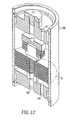
- FIGS. 12 and 13 illustrate a module 185 employing several fluid separation assemblies 110 of the present invention, wherein FIG. 13 is an enlarged section B of the module 185.
- Each of the fluid separation assemblies 110 are shown as a solid body for clarity. However, each of the fluid separation assemblies 110 are the same as the fluid separation assemblies 110 shown in FIGS. 5-11 .
- the module 185 has a feed gas inlet 191, a permeate outlet 190 and a discharge gas outlet 193.
- the fluid separation assemblies 110 are coaxially aligned.
- Distribution plates 187 are sandwiched between and separate the fluid separation assemblies 110.
- the distribution plates 187 are positioned on a shoulder of the gasket seats 136 in such a manner that they are positioned equidistant from the planar surface of the permeable membrane assemblies 114 and 132 in successive fluid separation assemblies 110.
- the distribution plates 187 are not fixedly connected to the gasket seats 136 and 160, but rather rest on a shoulder of the gasket seat 136. There is sufficient clearance between the central opening of the redistribution plate 187 and the shoulder on the female gasket seat 136 that the redistribution plates 187 and the fluid separation assemblies 110 are allowed to position themselves inside the wall of the membrane housing independently of the position of the fluid separation assemblies 110.
- Each distribution plate 187 has openings 189 therein.
- the fluid separation assemblies 110 are aligned one with the other such that each of the conduits 180 of the fluid separation assemblies 110 form a larger conduit 190.
- the path of the gas mixture containing hydrogen represented by arrow G, enters the opening 189 and travels along the outer surface of the fluid separation assembly 110, wherein some of the hydrogen of the gas mixture is free to enter the fluid separation assembly 110 by the permeable membranes 138 and 162 and is directed along path F into the larger conduit 190 and the remaining gas mixture follows arrow G and serpentines through the passageway, formed by the distribution plates 187, the fluid separation assemblies 110 and the interior wall 192 of the module 185.
- the gas mixture As the gas mixture travels through the passageway, it contacts the outer surfaces of several other fluid separation assemblies 110, wherein more of the hydrogen remaining in the gas mixture permeates the permeable membrane 138 and 162 and follows the path F resulting in this purified hydrogen entering the larger conduit 190.
- the remainder of the hydrogen depleted gas mixture exits through a port 193 located at the opposite end of the module 185 after flowing over the entire stack of fluid separation membrane assemblies 110.
Abstract
Description
- The present invention relates to apparatuses and methods for separation of a desired fluid from a fluid mixture. More particularly, the present invention is generally directed to a fluid separation assembly having a membrane permeable to a desired fluid and a wire mesh membrane support that supports the permeable membrane and has a barrier that prevents intermetallic diffusion bonding. This invention relates to metal membranes used for separating hydrogen gas from a mixture of gases.
- Several metal foils have been shown to be suitable for the separation of hydrogen gas from a gas mixture by a mechanism of diffusion or transfer of hydrogen ions or protons through the normally non-porous metal foil with molecular hydrogen being recoverable on the opposite side of the foil from the side contacting the gas mixture. Many workers in this field have employed different metals, metal alloys and different structures to optimize the separation of the hydrogen component of a gas mixture or to purify hydrogen under the wide variety of conditions that can be present in a hydrogen containing gas stream at or near the conditions for hydrogen production. The
U.S. Patents to Johann G.E. Cohn 3,238,700 andLeonard R. Rubin 3,172,742 are exemplary of the early work in this field which employed alloys of palladium to overcome some of the detrimental changes which can occur in the metal foil when subjected to substantial temperature changes in the presence of hydrogen, when produced typically by gas phase reactions such as the water gas shift reaction (steam over heated carbon or carbon containing materials), or the decomposition of hydrogen containing compounds. (Canadian Patent No.579,535 ). - It is therefore an objective of the present invention to provide a supported hydrogen permeable metal or metal alloy foil-containing structure which can operate successfully in the environments present in hydrogen production as well as being suitable for separation of hydrogen from gas streams containing hydrogen produced by any means.
- Generally, when separating a gas from a mixture of gases by diffusion, the gas mixture is typically brought into contact with a nonporous membrane which is selectively permeable to the gas that is desired to be separated from the gas mixture. The desired gas diffuses through the permeable membrane and is separated from the other gas mixture. A pressure differential between opposite sides of the permeable membrane is usually created such that the diffusion process proceeds more effectively, wherein a higher partial pressure of the gas to be separated is maintained on the gas mixture side of the permeable membrane. It is also desireable for the gas mixture and the selectively permeable membrane to be maintained at elevated temperatures to facilitate the separation of the desired gas from the gas mixture. This type of process can be used to separate hydrogen from a gas mixture containing hydrogen. Thus, in this application, the permeable membrane is permeable to hydrogen and is commonly constructed from palladium or a palladium alloy. The exposure to high temperatures and mechanical stresses created by the pressure differential dictates that the permeable membrane be supported in such a way that does not obstruct passage of the desired gas through the membrane.
- One type of conventional apparatus used for the separation of hydrogen from a gas mixture employs a woven refractory-type cloth for supporting the permeable membrane during the separation process. The disadvantage of this type of conventional membrane support is that the cloth support is susceptible to failure when it is exposed to high mechanical stresses associated with the differential pressure required to effect diffusion through the membrane material.
- Another conventional permeable membrane support is a metal gauze structure placed adjacent to the permeable membrane. The disadvantage of this type of support is that intermetallic diffusion bonding occurs between the membrane support and the permeable membrane when they are exposed to high pressures and high temperatures. The high pressure tends to compress the permeable membrane and the metal gauze together and the high temperatures tend to deteriorate the chemical bonds of those materials. Such undesirable condition results in migration of the molecules of the permeable membrane to the metal gauze membrane and the migration of molecules of
- the metal gauze membrane to the permeable membrane until a bond is formed between those two structures. This intermetallic diffusion bonding results in a composite material that is no longer permeable by the hydrogen gas.
-
EP-A-0783919 discloses a construction of composite hydrogen separation elements and modules utilising the same. At least one common-axis hole is provided through all components of the separation element and there is also provided a gas-tight seal, for example by welding, brazing, or diffusion bonding, around the periphery of the hole or holes through a coating metal layer of the element. In an embodiment a ceramic or glass fibre layer is used to present intermetallic diffusion -
US-46 99 637 discloses a hydrogen permeation membrane reinforced on both sides with a wire mesh comprising a nickel or nickel alloy coating with a thickness of a few microns. - Thus, the need exists for a method and apparatus for separating a desired fluid from a fluid mixture that can reliably withstand high operating pressures and temperatures.
- Another need exists for a permeable membrane and support arrangement for separating a desired fluid from a fluid mixture, wherein the permeable membrane is not susceptible to breakage or intermetallic diffusion bonding.
- Yet another need exists for a method of supporting a membrane that is permeable to a fluid, wherein the fluid permeable membrane is exposed to high temperatures and high pressures.
- For the present invention to be readily understood and practiced, preferred embodiments will be described in conjunction with the following figures wherein:
-
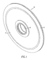
FIG. 1 is an isometric view of a membrane assembly according to the present invention before welding; -
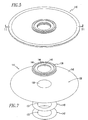
FIG. 2 is a top view of the membrane assembly ofFIG. 1 ; -
FIG. 2A is a sectional view of the membrane assembly ofFIG. 2 taken along the lines andarrows 2A; -
FIG. 3 is a partial sectional view in perspective of the edge detail of the membrane of the present invention; -
FIG. 4 is a partial cut away view of the membrane assembly of the present invention; -
FIG. 5 is a top isometric view of a fluid separation assembly of the present invention; -
FIG. 6 is an exploded isometric view of the fluid separation assembly of the present invention shown inFIG. 5 ; -
FIG. 7 is an exploded isometric view of the female permeable membrane subassembly of the present invention shown inFIG. 5 ; -
FIG. 8 is an exploded isometric view of the male permeable membrane subassembly of the present invention shown inFIG. 5 ; -
FIG. 9 is a sectional isometric view of the fluid separation assembly of the present invention; -
FIG. 10 is an enlarged view of section A of the fluid separation assembly shown inFIG. 9 ; -
FiG.11 is a cross-sectional view of the fluid separation assembly of the present invention shown inFIG. 5 taken along line 11-11; -
Fig. 12 is an isometric sectional diagrammatical view of a module employing several fluid separation assemblies of the present invention; and -
FIG.13 is an enlarged section B of the module shown inFIG. 12 . - The invention provides a fluid separation assembly in accordance with
claim 1 of the appended claims. - The hydrogen permeable membrane structure of the present invention comprises a disc shaped supported metal foil sized to overlap a support plate or disc capable of passing product gases diffused or transferred through the metal foil, which disc terminates at its periphery with a pair of beveled sheet metal support rings overlying the support plate and a pair of beveled sheet metal capture rings matched in shape to the beveled support rings to capture the hydrogen permeable membrane foil there between, the assembly terminating in an edge formed by the edges of the capture rings and support rings with the captured foil, which edge is then hermetically scaled by a weld bead joining all of the rings together. The assembly includes means for centrally removing the separated hydrogen from the support plate.
- The present invention provides a fluid separation assembly having a fluid permeable membrane and a wire mesh membrane support adjacent the fluid permeable membrane, wherein the wire mesh membrane support has an intermetallic diffusion bonding barrier.
- The present invention further provides a method for separating a desired fluid from a fluid mixture in accordance with claim 14 of the appended claims. Other details, objects and advantages of the present invention will become more apparent with the following description of the present invention.
- The present invention will be described below in terms of apparatuses and methods for separation of hydrogen from a mixture of gases. It should be noted that describing the present invention in terms of a hydrogen separation assembly is for illustrative purposes and the advantages of the present invention may be realized using other structures and technologies that have a need for such apparatuses and methods for separation of a desired fluid from a fluid mixture containing the desired fluid.
- It is to be further understood that the Figures and descriptions of the present invention have been simplified to illustrate elements that are relevant for a clear understanding of the present invention, while eliminating, for purposes of clarity, other elements and/or descriptions thereof found in a hydrogen separation assembly. Those of ordinary skill in the art will recognise that other elements may be desirable in order to implement the present invention. However, because such elements are well known in the art, and because they do not facilitate a better understanding of the present invention, a discussion of such elements is not provided herein.
- In the manufacture of a metal membrane based gas separation device, it is necessary to eliminate all possible leak paths between the feed side of the membrane and the product or permeate side of the membrane. This is done to maintain the highest possible purity of the product stream. Typically, a membrane used in this type of a device is very thin and consequently of low mechanical strength. A mechanical support, placed under the membrane on the product side, allows the membrane to function under high differential pressures at elevated temperatures. If membrane material is placed on both sides of the mechanical support, then the support itself is loaded under compressive stress during operation. Using this type of a design, the mechanical support can be less robust than would be necessary if it were loaded from one side only.
- The present invention provides a way of sealing each membrane "half" independent of the mechanical support so that all possible leak paths are eliminated. If both membrane sheets are joined at their periphery using a single seam type weld to join parts, the probability of a leak through a welded seam is substantially reduced.
- Many methods of the joining of thin metal foils used for hydrogen permeable membranes are known. Efforts to achieve a hermetic seal of thin foil type membranes with welding, brazing or diffusion bonding are described in
U.S. Patent No. 5,645,626 . Additional efforts at a brazed joint are described in Canadian Patent Application Number436,620 . The problems with a brazed type joint occur because of the possibility of the brazing alloy contaminating the membrane surface during the brazing operation with metals, flux compounds, or other substances that would interfere with the membranes ability to transport hydrogen during operation. - Diffusion bonding of membrane foils as a means of attachment to fabricated support members is limited by the requirement that a hermetic seal in a bonded joint can only occur when the material in the bonding zone enters into the liquid stage at some time during the bonding process.
- The present invention involves the joining of two thin foil membranes (approx. 25 micron/0.001 inch) using commercially available welding technology. A single weld joint hermetically seals both membranes in one pass, reducing the probability of a failed weld joint due to weld induced stress, contamination present in the base metals, and of porosity in the finished weld by approximately 50%. The completed joint has advantages over present technology in the areas of reliability and ease of manufacturing.
- The hydrogen separation membrane of the present invention is therefore an improvement over the membrane structure described in
U.S. Patent No. 5,139,541 . - The
membrane support structure 10 of the present invention is, as shown inFig. 1 , a disc shaped member designed to contact the hydrogen containing gas with both of its exterior surfaces. The exposedexterior surface 12 of the foil is sandwiched under theouter ring 13 in a manner more fully described hereinafter. The central hole communicates with the interior space of the disc for removal of the hydrogen. The reverse side of the disc (not shown) is identical as can be seen onFigs. 2 and 2A . The internal support disc has a hole corresponding to the interior of thecentral support structure 21. Thedisc 20 has a solid perimeter which is shown in section at 25. Slots are provided in the disc which radiate radially outward from its central hole to terminate at the edge of the outer perimeter. The edges of the slots are shown schematically at 27,28 and 29 for example. Thefoil 30 is received on both faces of thedisc 10. Hydrogen will be transported from the exterior of thedisc 10 through thefoil 30 and into aslot 35 in the support disc from where it can be removed through a central conduit (not shown) since the edges of the slots (for example 27, 28, 29) communicate with the opening (hole 15) and the central conduit. Other means for permitting the exhaust of the hydrogen can be provided i.e. such as grooves instead of slots or surface texturing or the like. - As previously described, the edge structure for the disc is critical for achieving a gas tight seal. Likewise, the foil preferably will be supported on an inert fabric such as woven fiberglass or a woven or non-woven ceramic material. Referring now to
Fig. 3 , thesupport disc 20 is covered on both sides with a layer ofinert fabric 31. The hydrogen permeablemetal membrane foil 30 is received over thefabric 31. A pair of sheet metal support rings 36 and 37 are affixed to thesupport disc 20 around its periphery so as not to occlude the slots. The beveled support rings 36 and 37 are dimensional to meet and form an edge. Thefoil fabric 31 received on thefabric 31 supported by thesupport disc 20. A pair of sheet metal capture rings 40 and 41 are sized to mate with the support rings 36 and 37 respectively and capture thefoil weld bead 50 joins all of the rings together. Thedisc 20, capture rings 40 and 41, and support rings 36 and 37 are all made from materials which are compatible with the end use environment for the membrane discs. - This invention differs from the present technology by reducing the total length of welded or sealed joints for a given pair of membranes with comparable outside diameters. The invention also allows dimensional changes due to the different coefficients of thermal expansion used in the materials of the welded joint and dimensional changes encountered when the membrane material is saturated with hydrogen which occurs independently of other components in the assembly. This has the effect of further reducing stress on the membrane under operating conditions. Additionally, this type of joint allows for the selection of lower cost materials of construction that are not physically a part of the welded joint further reducing the cost of manufacture.
- The fabrication of these parts into a completed assembly is accomplished by assembly into a welding fixture that clamps the parts together. The membrane material is mechanically forced between the bottom membrane support and the membrane cover rings during clamping into the weld fixture so that the outer edges are held tightly together in tight contact with the membrane. This clamped assembly is then seam welded at the outer perimeter. The single weld bead fuses the outer edges of the upper and lower bottom membrane support rings, the upper and lower membranes, and the upper and lower membrane cover rings into a leak proof unit.
- The actual seam weld can be effected by a number of commercially available technologies, including but not limited to laser, electron beam, and tungsten inert gas (TIG) welding. The welded seam can be achieved with or without the addition of filler material to the weld zone. This type of weld may have other applications requiring welding of thin metal foils for other uses outside the membrane application described.
- An assembly of forty-three individual discs prepared as described herein, containing approximately 1,86 square metres (twenty square feet) of total membrane area were operated at 300° C and 4.14MPa (600 psig) for a total of 200 hours with no noticeable decline in hydrogen separation function. The permeate side of the assembly was operated at a pressure of from about 1.03 to 2.08 MPa (15 to 30 psig) subjecting the assembly to a differential pressure across each membrane of 3.93 to 4.03 MPa (570-585 psig). The assembly was also subjected to about 30 cycles of operation from ambient conditions of temperature and pressure to the operating temperatures and pressures described without failure of the welded joint.
- The limitations to maintaining weld integrity and thus a hermetically sealed weld joint are primarily in the selection of materials for the bottom support and top cover rings that are compatible with the thin metal foil to be welded and selecting the proper weld parameters of the equipment used to make the weld.
-
FIGS. 5 and6 illustrate one embodiment of thefluid separation assembly 110 of the present invention, whereinFIG. 6 is an exploded view of thefluid separation assembly 110 shown inFIG. 5 . Thefluid separation assembly 110 comprisesfirst membrane retainers 112, afemale membrane subassembly 114, afirst membrane gasket 116, a first wiremesh membrane support 118,second membrane retainers 120, a slottedpermeate plate 122, apermeate rim 124, a second wiremesh membrane support 128, asecond membrane gasket 130 and amale membrane subassembly 132. In one embodiment, thefirst retainers 112 may be substantially flat ring members having an outside diameter equal to the diameter of the female andmale membrane subassemblies first membrane retainers 112 each have a centrally disposedopening first membrane retainers 112 may be made from Monel 400 (UNS N 04400); however, other materials that are compatible with the welding process, discussed below, may also be used. It will also be appreciated that whilefirst retainers 112 are shown as comprising substantially annular members they may have other desired shapes and other thicknesses. -
FIG. 7 is an exploded view of a femalepermeable membrane subassembly 114. In this embodiment,female membrane subassembly 114, comprises afemale gasket seat 136, a hydrogenpermeable membrane 138, an innerdiameter membrane gasket 140 and acenter support washer 142. In this embodiment, thefemale gasket seat 136 is a substantiallyflat ring member 144 having a raisedface 146 extending around thering member 144 and a centrally disposedopening 145. It will be appreciated that while this embodiment is shown with gasket seats with this configurations or materials that may be used. Thefemale gasket seat 136 may be made from Monel 400; however, other materials such as nickel, copper, nickel alloys, copper alloys, or other alloys that provide for compatible fusion with the chosen permeable membrane material during welding may be used. In this embodiment, the hydrogenpermeable membrane 138 is a substantially planar member having a circular configuration, opposingsides 148 and a centrally disposedcircular opening 150. The innerdiameter membrane gasket 140 is also a flat ring member having a centrally disposedopening 151. Also in this embodiment, the innerdiameter membrane gasket 140 may be made from Monel 400 (UNS N 04400); however, other materials such as nickel, copper, nickel alloys, copper alloys, or other alloys that provide for compatible fusion with the chosen permeable membrane material during welding may be used. Thecenter support washer 142 is a flat ring member having a centrally disposedopening 153. Thecenter support washer 142 may be made of Monel 400 (UNS N 04400); however, other materials such as nickel, copper, nickel alloys, copper alloys, or other alloys that provide for compatible fusion with the chosen permeable membrane material or alloy during welding may be used. - Referring back to
FIG. 6 , in this embodiment, the first andsecond membrane gaskets opening second membrane gaskets fluid separation assembly 110 and which is discussed below. The first andsecond membrane gaskets - Also in this embodiment, the first and second wire mesh membrane supports 118 and 128 are planar, ring-shaped members having centrally disposed
openings hydrogen permeably membranes - Also in this embodiment, the
second membrane retainers 120 each are a substantially flat ring member. Oneretainer 120 has a centrally disposedopening 159 andretainer 120 has it centrally disposedopening 161. SeeFIG. 6 . Theseretainers 120 may be the same thickness as the first and second wire mesh membrane supports 118 and 128. Thesecond membrane retainers 120 may be made from a material that is compatible with the weld, discussed below, such as Monel 400 (UNS N 004400) and nickel, copper, nickel alloys, copper alloys, precious metals or alloys, or other alloys that provide for compatible fusion with the chosen membrane material or alloy during welding may be used. - In this embodiment, the slotted
permeate plate 122 is a steel plate having a plurality ofslots 156 extending radially and outwardly from acentral opening 158 in the direction of the periphery of the slottedpermeate plate 122. The number ofslots 156 in a slottedpermeate plate 122 may range from approximately 10 to 72. However, other suitable slot densities could conceivably be employed. Thepermeate plate rim 124 is a substantially flat ring member having a centrally disposedopening 163 and an inner diameter larger than the outer diameter of the slottedpermeate plate 122. Thepermeate plate rim 124 is made from Monel 400 (UNS N 04400); however, other materials can also be used such as nickel, copper, nickel alloys, copper alloys, precious metals or alloys or other alloys that provide for compatible fusion with the chosen membrane material or alloy during welding. -
FIG. 8 is an exploded view of the malepermeable membrane subassembly 132. Themale membrane subassembly 132 comprises amale gasket seat 160, a hydrogenpermeable membrane 162, an innerdiameter membrane gasket 164, and acenter support washer 166. The hydrogenpermeable membranes permeable membrane 162, the innerdiameter membrane gasket 164, and thecenter support washer 166 are similar in structure to the hydrogenpermeable membrane 138, the innerdiameter membrane gasket 140 and thecenter support washer 142, respectively, discussed above. Themale gasket seat 160 is a substantiallyplanar ring member 168 having acircular protuberance 170 extending around a centrally disposedopening 172. In this embodiment, thefemale gasket seat 136 and themale gasket seat 160 are made of a high strength alloy material that is compatible with the weld such as Monel 400. The innerdiameter member gaskets diameter membrane gaskets -
FIGS. 9 through 11 are various cross-sectional views of the assembledfluid separation assembly 110 of the present invention, whereinFIG. 10 is an enlarged view of section A of thefluid separation assembly 110 shown inFIG. 9 , andFIG. 11 is a cross-sectional plan view of the assembledfluid separation assembly 110. When assembling the components of thefluid separation assembly 110 shown inFIGS. 6-8 , thefemale membrane subassembly 114 and themale membrane subassembly 132 are initially assembled. Thefemale gasket seat 136, thepermeable membrane 138, the innerdiameter membrane gasket 140 and thecenter support washer 142 are placed adjacent one another, as shown inFIG. 11 , such that their centraldisposed openings first weld 171, shown inFIG. 11 , is placed at the openings thereof. Thefirst weld 171 takes the form of a weld bead creating a hermetic seal between thefemale gasket seat 136, thepermeable membrane 138, the innerdiameter membrane gasket 140 and thecenter support washer 142. Theweld 171 can be effected by a number of commercially available technologies, including but not limited to, lasers, electron beam and tungsten inert gas (TIG) welding. Alternative joining technologies such as brazing or soldering may also be employed with the desired result being a gas tight bond between thegasket seat 136 and thepermeable membrane 138. Likewise, the components of themale membrane subassembly 132, which include themale gasket seat 160, thepermeable membrane 162, the innerdiameter membrane gasket 164 and thecenter support washer 166 are also placed adjacent one another, as shown inFIG. 11 , such that their centrally disposedopenings second weld bead 173, shown inFIG. 11 , is placed around the circumference of theopenings weld 173 can be effected by a number of commercially available technologies, including but not limited to, laser, electron beam, and tungsten inert gas (TIG) welding. - After the components of the
female membrane subassembly 114 and the components of themale membrane subassembly 132 have each been connected by thewelds fluid separation assembly 110. As shown inFIG. 6 , the first andsecond retainer members male membrane subassemblies outer diameter gaskets permeate plate 122 and thepermeate rim 124 are aligned such that their centrally disposed openings are coaxially aligned. As shown inFIG. 11 , these components are retained in that configuration by placing aweld 174 at the outer periphery of the first andsecond retainer members male membrane subassemblies diameter membranes gaskets permeate rim 124. Alternatively, these parts could be assembled such that their centrally disposed openings are coaxially aligned, as shown inFIG. 11 , and connected to one another by performing a brazing or soldering operation at the outer periphery of the first andsecond retainer members male membrane subassemblies diameter membrane gaskets permeate rim 124. As seen inFIG. 10 , aspace 175 is provided between the slottedpermeate plate 122 and thepermeate rim 124 which permits expansion and contraction of the components of thefluid separation assembly 110 resulting from the change in temperature. Assembled, thefluid separation assembly 110 may have a thickness ranging from 0.025 to 0.318 can (0.010 inches to 0.125 inches.) depending upon the thicknesses of the components employed. - When separating the hydrogen from a mixture of gas that includes hydrogen, the gas mixture is directed towards the
permeable membranes female membrane subassembly 114 end themale membrane subassembly 132, respectively, in the directions D and E, as shown inFIG. 11 . For clarity, thepermeable membranes male membrane subassemblies FIG. 11 as being spaced from the first and second wire mesh membrane supports 118 and 128; however, in use, thepermeable membranes permeable membranes permeable membranes permeate plate 122 where the hydrogen enters aspecific slot 156 and to be directed toward the central axis C by the passageways formed by theslots 156. The central openings of the components of thefluid separation assembly 110, shown inFIG. 6 , form aconduit 180 wherein the purified hydrogen is collected and transported to a desired location. Theconduit 180 may have a diameter of between approximately 0.64 cm (0.25 inches) and 2.54 cm (1 inch). The diameter is determined by the components of thefluid separation assembly 110 and by the desire that the hydrogen flow be substantially unimpeded. The non-hydrogen gases in the gas mixture are prevented from entering thefluid separation assembly 110 by the fluidpermeable membranes fluid separation assembly 110 in this embodiment. -
FIGS. 12 and13 illustrate amodule 185 employing severalfluid separation assemblies 110 of the present invention, whereinFIG. 13 is an enlarged section B of themodule 185. Each of thefluid separation assemblies 110 are shown as a solid body for clarity. However, each of thefluid separation assemblies 110 are the same as thefluid separation assemblies 110 shown inFIGS. 5-11 . Themodule 185 has afeed gas inlet 191, apermeate outlet 190 and adischarge gas outlet 193. Thefluid separation assemblies 110 are coaxially aligned.Distribution plates 187 are sandwiched between and separate thefluid separation assemblies 110. Thedistribution plates 187 are positioned on a shoulder of the gasket seats 136 in such a manner that they are positioned equidistant from the planar surface of thepermeable membrane assemblies fluid separation assemblies 110. Thedistribution plates 187 are not fixedly connected to the gasket seats 136 and 160, but rather rest on a shoulder of thegasket seat 136. There is sufficient clearance between the central opening of theredistribution plate 187 and the shoulder on thefemale gasket seat 136 that theredistribution plates 187 and thefluid separation assemblies 110 are allowed to position themselves inside the wall of the membrane housing independently of the position of thefluid separation assemblies 110. Eachdistribution plate 187 hasopenings 189 therein. Thefluid separation assemblies 110 are aligned one with the other such that each of theconduits 180 of thefluid separation assemblies 110 form alarger conduit 190. The path of the gas mixture containing hydrogen, represented by arrow G, enters theopening 189 and travels along the outer surface of thefluid separation assembly 110, wherein some of the hydrogen of the gas mixture is free to enter thefluid separation assembly 110 by thepermeable membranes larger conduit 190 and the remaining gas mixture follows arrow G and serpentines through the passageway, formed by thedistribution plates 187, thefluid separation assemblies 110 and theinterior wall 192 of themodule 185. As the gas mixture travels through the passageway, it contacts the outer surfaces of several otherfluid separation assemblies 110, wherein more of the hydrogen remaining in the gas mixture permeates thepermeable membrane larger conduit 190. The remainder of the hydrogen depleted gas mixture exits through aport 193 located at the opposite end of themodule 185 after flowing over the entire stack of fluidseparation membrane assemblies 110. - Although the present invention has been described in conjunction with the above described embodiments thereof, it is expected that many modifications and variations will be developed. The following claims cover all such modifications and variations.
Claims (19)
- A fluid separation assembly (110) comprising:a. a permeate plate (122) having a first surface, a second surface, a fluid outlet (158) and fluid passageways (156) extending from said fluid outlet (158) in the direction of the periphery of the permeable plate;b. first and second wire mesh membrane supports (118,128) adjacent said first surface and said second surface of said permeate plate (122), respectively, each of said first and second wire mesh membrane supports (118,128) comprising a wire mesh comprised of a metal or a metal alloy and having a coaling that is an intermetallic diffusion bonding barrier, said intermetallic diffusion bonding barrier containing a compound selected from the group consisting of oxides, nitrides, borides, silicides, carbides and aluminides, and having an opening (152) aligned with said fluid outlet (158) of said permeate plate (122);c. first and second hydrogen permeable membranes (138,162) comprising a metal or metal alloy, said first hydrogen permeable membrane (138) adjacent a surface of said first wire mesh membrane support (118) opposite said permeate plate (122), said second hydrogen permeable membrane (162) adjacent a surface of said second wire mesh membrane (128) opposite said permeate plate (122), each of said first and second permeable membranes (138,162) having an opening (150,181) aligned with said fluid outlet (158).
- The fluid separation assembly (110) according to claim 1, wherein the permeate plate (122) is a slotted permeate plate.
- The fluid separation assembly (110) of claim 2, wherein said openings of said hydrogen permeable membranes (138,162) and said membrane supports (118,128) and said outlet of said permeate plate (122) are centrally disposed and coaxially aligned to form a central conduit (180).
- The fluid separation assembly (110) of claim 3, wherein said hydrogen permeable membranes (138,162), said membrane supports (118,128) and said permeate plate (122) are substantially flat and ring-shaped, said permeate plate (122) includes slots (156) defining said fluid passageways (156), and said slots (156) are radially disposed.
- The fluid separation assembly (110) of claim 1, wherein each of said hydrogen permeable membranes (138,162) further comprises a gasket seat (136,160), a membrane gasket (140,164), and a washer (142,166) disposed about said opening (152,145,172) to form a first and second membrane subassembly (114,132), wherein said gasket seats (136,160), said membrane gaskets (140,164) and said washers (142,166) are connected to said hydrogen permeable membrane (138,162).
- The fluid separation assembly (110) of claim 5, further comprising a hermetic seal, said hermetic seal comprising weld bead (171,173) connected to each of said first and second membrane subassemblies (114,132).
- The fluid separation assembly (110) of claim 2, further comprising gaskets (116,130), one of said gaskets (116,130) adjacent each of said first and second wire mesh membrane supports (118,128).
- The fluid separation assembly (110) of claim 7, further comprising a permeate rim (124) surrounding said permeate plate (122) and wherein said permeate rim (124), said first retainers (112), said second retainers (120), said permeable membranes (138,162) and said gaskets (116,130) are joined together at their peripheries, and wherein a gap (175) is defined between the said permeate plate (122) and said permeate rim (124).
- The fluid separation assembly (110) according to claim 8, wherein said permeate rim (124), said first retainers (112), said second retainers (120), said permeable membranes (138,162) and said gaskets (116,130) are joined together by a weld bead (174) at their peripheries.
- A fluid separation module (185), comprising a plurality of fluid separation assemblies (110) in accordance with claim 8 or claim 9.
- The fluid separation assembly (110) of claim 1, wherein said hydrogen permeable membranes (138,162) comprise palladium or a palladium alloy.
- The fluid separation assembly (110) of claim 1, wherein said wire mesh membrane supports (118,128) comprise stainless steel.
- The fluid separation assembly (110) of claim 1, wherein the intermetallic diffusion bonding barrier contains one of an oxide and a nitride.
- A method for separating a desired fluid from a fluid mixture, comprising:providing a fluid separation assembly (110) as recited in any one of the preceding claims; andcontacting the hydrogen permeable membranes (138,162) of the fluid separation assembly (110) with the fluid mixture.
- The method of claim 14, wherein the intermetallic diffusion bonding barrier is a thin film.
- The method of claim 14, wherein the wire mesh membrane support is a stainless steel screen having a mesh count ranging from approximately 7 to 394 mesh per centimetre (19 to 1000 mesh per inch).
- A method of making a fluid separation assembly, comprising the steps ofa. providing a fluid separation assembly (110) as recited in claim 8 or claim 9; andb. hermetically sealing the first retainer (112), the gasket (116,130) and the second retainer (120) at their peripheries.
- The method according to claim 17, wherein the intermetallic diffusion bonding barrier is thin film.
- The method according to claim 18, wherein the wire mesh membrane support (118,128) is a stainless steel screen with a mesh count ranging from approximately 7 to 394 mesh per centimetre (19 to 1000 mesh per inch).
Applications Claiming Priority (5)
| Application Number | Priority Date | Filing Date | Title |
|---|---|---|---|
| US10778498P | 1998-11-10 | 1998-11-10 | |
| US107784P | 1998-11-10 | ||
| US09/422,505 US6602325B1 (en) | 1999-10-21 | 1999-10-21 | Fluid separation assembly |
| US422505 | 1999-10-21 | ||
| PCT/US1999/026527 WO2000027507A1 (en) | 1998-11-10 | 1999-11-10 | Hydrogen separation membrane |
Publications (2)
| Publication Number | Publication Date |
|---|---|
| EP1137477A1 EP1137477A1 (en) | 2001-10-04 |
| EP1137477B1 true EP1137477B1 (en) | 2010-08-04 |
Family
ID=26805148
Family Applications (1)
| Application Number | Title | Priority Date | Filing Date |
|---|---|---|---|
| EP99961621A Expired - Lifetime EP1137477B1 (en) | 1998-11-10 | 1999-11-10 | Hydrogen separation membrane assembly |
Country Status (13)
| Country | Link |
|---|---|
| US (1) | US6582499B2 (en) |
| EP (1) | EP1137477B1 (en) |
| JP (1) | JP2002529220A (en) |
| KR (1) | KR100592625B1 (en) |
| AU (1) | AU767080B2 (en) |
| CA (1) | CA2351191C (en) |
| CH (1) | CH694150A5 (en) |
| DE (1) | DE19983751B4 (en) |
| DK (2) | DK177264B1 (en) |
| ES (1) | ES2199663B1 (en) |
| FI (1) | FI122170B (en) |
| SE (1) | SE526425C2 (en) |
| WO (1) | WO2000027507A1 (en) |
Families Citing this family (24)
| Publication number | Priority date | Publication date | Assignee | Title |
|---|---|---|---|---|
| US6494937B1 (en) | 2001-09-27 | 2002-12-17 | Idatech, Llc | Hydrogen purification devices, components and fuel processing systems containing the same |
| US6319306B1 (en) * | 2000-03-23 | 2001-11-20 | Idatech, Llc | Hydrogen-selective metal membrane modules and method of forming the same |
| US6835232B2 (en) * | 1998-11-10 | 2004-12-28 | Frost Chester B | Fluid separation assembly and fluid separation module |
| US6767389B2 (en) * | 1999-03-22 | 2004-07-27 | Idatech, Llc | Hydrogen-selective metal membranes, membrane modules, purification assemblies and methods of forming the same |
| DE10044406A1 (en) * | 1999-10-19 | 2001-07-05 | Ford Global Tech Inc | Hydrogen separator and process for its manufacture |
| US6660069B2 (en) * | 2001-07-23 | 2003-12-09 | Toyota Jidosha Kabushiki Kaisha | Hydrogen extraction unit |
| CN100427186C (en) * | 2001-09-26 | 2008-10-22 | 东洋钢钣株式会社 | Gas separating equipment and producing method thereof |
| KR100715103B1 (en) * | 2001-10-26 | 2007-05-07 | 에스케이 주식회사 | Hydrogen purification module |
| US20030230623A1 (en) * | 2002-06-17 | 2003-12-18 | Fleckenstein Joseph Edward | Means for brazing palladium alloy elements intended for hydrogen purifier |
| US7353982B2 (en) * | 2003-11-25 | 2008-04-08 | Membrane Reactor Technologies Ltd. | Diffusion bonding for metallic membrane joining with metallic module |
| CA2463386A1 (en) * | 2004-04-02 | 2005-10-02 | Mcmaster University | Membrane adsorption module |
| FR2873935B1 (en) * | 2004-08-06 | 2006-11-03 | Cie D Etudes Des Technologies | PURIFIED HYDROGEN PRODUCTION STAGE SYSTEM FROM A REACTIONAL GAS MIXTURE COMPRISING A HYDROCARBON COMPOUND |
| DE102004057107B8 (en) * | 2004-11-26 | 2016-07-28 | A3 Water Solutions Gmbh | Frameless, plate-shaped filtration body and filtration module |
| JP2007000858A (en) * | 2005-05-23 | 2007-01-11 | Kobe Steel Ltd | Hydrogen permeation member and its manufacturing method |
| JP4853617B2 (en) * | 2005-11-09 | 2012-01-11 | 三菱瓦斯化学株式会社 | Hydrogen purification module |
| US20110061376A1 (en) * | 2009-02-17 | 2011-03-17 | Mcalister Technologies, Llc | Energy conversion assemblies and associated methods of use and manufacture |
| US8110022B2 (en) * | 2009-04-16 | 2012-02-07 | Genesis Fueltech, Inc. | Hydrogen purifier module and method for forming the same |
| US8226750B2 (en) * | 2009-05-05 | 2012-07-24 | Genesis Fueltech, Inc. | Hydrogen purifier module with membrane support |
| US10717040B2 (en) | 2012-08-30 | 2020-07-21 | Element 1 Corp. | Hydrogen purification devices |
| US11738305B2 (en) | 2012-08-30 | 2023-08-29 | Element 1 Corp | Hydrogen purification devices |
| US9187324B2 (en) | 2012-08-30 | 2015-11-17 | Element 1 Corp. | Hydrogen generation assemblies and hydrogen purification devices |
| KR101406868B1 (en) * | 2012-11-15 | 2014-06-13 | 한국원자력연구원 | Flange-type apparatus for hydrogen isotopes permeation |
| US10476093B2 (en) | 2016-04-15 | 2019-11-12 | Chung-Hsin Electric & Machinery Mfg. Corp. | Membrane modules for hydrogen separation and fuel processors and fuel cell systems including the same |
| US11712655B2 (en) | 2020-11-30 | 2023-08-01 | H2 Powertech, Llc | Membrane-based hydrogen purifiers |
Family Cites Families (101)
| Publication number | Priority date | Publication date | Assignee | Title |
|---|---|---|---|---|
| CA724479A (en) * | 1965-12-28 | P. Murphy Kevin | Process of separating helium and/or hydrogen from gaseous mixtures containing same | |
| US2824620A (en) * | 1955-09-12 | 1958-02-25 | Universal Oil Prod Co | Purification of hydrogen utilizing hydrogen-permeable membranes |
| US3206198A (en) * | 1962-10-09 | 1965-09-14 | Kenneth C Sherman | Mechanism for sorting and delivering bowling balls and pins |
| US3350176A (en) * | 1964-03-24 | 1967-10-31 | Engelhard Ind Inc | Hydrogen generator |
| US3336730A (en) * | 1964-11-17 | 1967-08-22 | Union Carbide Corp | Hydrogen continuous production method and apparatus |
| US3344586A (en) * | 1965-06-22 | 1967-10-03 | Engelhard Ind Inc | Gas separation apparatus |
| US3428476A (en) * | 1965-06-22 | 1969-02-18 | Engelhard Min & Chem | Method for producing hydrogen diffusion cells |
| US3450500A (en) * | 1965-08-03 | 1969-06-17 | United Aircraft Corp | Method for catalytically reforming hydrogen-containing carbonaceous feed-stocks by simultaneous abstractions through a membrane selectively permeable to hydrogen |
| US3368329A (en) * | 1965-08-10 | 1968-02-13 | Eguchi Takashi | Hydrogen purification apparatus |
| US3447288A (en) * | 1965-08-23 | 1969-06-03 | Prototeck Inc | Gas-diffusion assembly including thin hydrogen-permeable impervious foil |
| US3398834A (en) * | 1966-10-10 | 1968-08-27 | Aerojet General Co | Reverse osmosis water purification apparatus and cell therefor |
| US3439474A (en) * | 1967-08-17 | 1969-04-22 | Union Carbide Corp | Method for hydrogen separation and purification |
| US3469944A (en) * | 1968-05-13 | 1969-09-30 | Joseph P Bocard | Process and apparatus for the manufacture of hydrogen for fuel cells |
| US3486301A (en) * | 1968-08-05 | 1969-12-30 | Engelhard Min & Chem | Hydrogen diffusion apparatus |
| US3520803A (en) * | 1968-12-24 | 1970-07-21 | Ionics | Membrane fluid separation apparatus and process |
| GB1287584A (en) * | 1969-02-07 | 1972-08-31 | Johnson Matthey Co Ltd | Diffusion cell |
| US3564819A (en) * | 1970-02-24 | 1971-02-23 | Gen Electric | Membrane package construction |
| US3665680A (en) * | 1970-12-18 | 1972-05-30 | Engelhard Min & Chem | Hydrogen diffusion apparatus |
| US3713270A (en) * | 1971-05-24 | 1973-01-30 | Nat Res Dev | Hydrogen diffusion membranes |
| BE788610A (en) * | 1971-09-09 | 1973-03-08 | Rhone Poulenc Sa | MEMBRANE SEPARATOR APPARATUS USED IN GAS PERMEATION AND PERVAPORATION |
| JPS4873388A (en) * | 1971-12-29 | 1973-10-03 | ||
| US3761382A (en) * | 1972-06-21 | 1973-09-25 | Triangle Environment Corp | Ers and the like apparatus for generating purifying and delivering hydrogen for analyz |
| FR2207747B1 (en) * | 1972-11-24 | 1975-07-04 | Rhone Poulenc Ind | |
| BE795954A (en) * | 1973-02-05 | 1973-08-27 | Uralsky Politekhn Inst | PROCESS FOR OBTAINING VERY HIGH PURITY HYDROGEN |
| US4072625A (en) * | 1975-03-03 | 1978-02-07 | Imperial Chemical Industries Limited | Steam-hydrocarbon process |
| US4003725A (en) * | 1975-05-12 | 1977-01-18 | Trienco, Inc. | Apparatus for purifying hydrogen gas |
| US3972695A (en) * | 1975-05-12 | 1976-08-03 | Trienco, Inc. | Hydrogen purifier |
| US4056373A (en) * | 1976-05-12 | 1977-11-01 | Resource Systems, Inc. | Hydrogen-purification apparatus with palladium-alloy filter coil |
| US4132668A (en) * | 1977-04-06 | 1979-01-02 | Gryaznov Vladimir M | Method of preparing a hydrogen-permeable membrane catalyst on a base of palladium or its alloys for the hydrogenation of unsaturated organic compounds |
| CH625712A5 (en) * | 1977-12-01 | 1981-10-15 | Kilcher Chemie Ag | |
| SE7801231L (en) * | 1978-02-02 | 1979-08-03 | Gambro Ab | DEVICE FOR DIFFUSION OF THE SUBJECT BETWEEN TWO FLUIDA SEPARATED BY A SEMIPERMABLE MEMBRANE |
| US4254086A (en) * | 1978-12-27 | 1981-03-03 | Sanders Alfred P | Endothermal water decomposition unit for producing hydrogen and oxygen |
| US4468235A (en) * | 1979-02-15 | 1984-08-28 | Hill Eugene F | Hydrogen separation using coated titanium alloys |
| US4248688A (en) * | 1979-09-04 | 1981-02-03 | International Business Machines Corporation | Ion milling of thin metal films |
| US4331520A (en) * | 1979-10-26 | 1982-05-25 | Prototech Company | Process for the recovery of hydrogen-reduced metals, ions and the like at porous hydrophobic catalytic barriers |
| US4319923A (en) * | 1979-12-26 | 1982-03-16 | Western Electric Co., Inc. | Recovery of gold and/or palladium from an iodide-iodine etching solution |
| JPS5935631B2 (en) * | 1980-07-24 | 1984-08-29 | テルモ株式会社 | Body fluid “filtration” device |
| US4422911A (en) * | 1982-06-14 | 1983-12-27 | Prototech Company | Method of recovering hydrogen-reduced metals, ions and the like at porous catalytic barriers and apparatus therefor |
| EP0106523B1 (en) * | 1982-09-13 | 1987-04-01 | Johnson Matthey Public Limited Company | Diffusion cell |
| US4472176A (en) * | 1983-08-01 | 1984-09-18 | Resource Systems, Inc. | Apparatus and method for the production of pure hydrogen from a hydrogen-containing crude gas |
| DE3332348A1 (en) * | 1983-09-08 | 1985-04-04 | Kernforschungsanlage Jülich GmbH, 5170 Jülich | HYDROGEN PERMEATION WALL |
| DE3332345C2 (en) * | 1983-09-08 | 1986-08-07 | Doduco KG Dr. Eugen Dürrwächter, 7530 Pforzheim | Filter material made of metal mesh |
| DE3332346A1 (en) * | 1983-09-08 | 1985-04-04 | Kernforschungsanlage Jülich GmbH, 5170 Jülich | HYDROGEN PERMEATION WALL, METHOD FOR PRODUCING THE SAME AND THE USE THEREOF |
| DE3424208A1 (en) * | 1984-06-30 | 1986-01-16 | Kernforschungsanlage Jülich GmbH, 5170 Jülich | METHOD AND DEVICE FOR INCREASING THE SALES OF GAS REACTIONS PROCESSING WITH HYDROGEN PRODUCTION |
| US4613436A (en) * | 1984-10-31 | 1986-09-23 | Separex Corporation | Membrane assembly for fluid separations-disk |
| US4810485A (en) * | 1986-08-25 | 1989-03-07 | Institute Of Gas Technology | Hydrogen forming reaction process |
| JPH0642940B2 (en) * | 1987-03-31 | 1994-06-08 | 東洋エンジニアリング株式会社 | Device for gas endothermic reaction |
| JP2572612B2 (en) * | 1987-11-30 | 1997-01-16 | 日本パイオニクス株式会社 | Hydrogen purification method |
| JP2596767B2 (en) * | 1987-11-30 | 1997-04-02 | 日本パイオニクス株式会社 | Method and apparatus for purifying hydrogen |
| JPH07112532B2 (en) * | 1988-04-13 | 1995-12-06 | 昭和アルミニウム株式会社 | Method for manufacturing filtration membrane |
| JPH0217918A (en) * | 1988-07-06 | 1990-01-22 | Sanyo Chem Ind Ltd | Gas separation membrane module |
| FR2637817B1 (en) * | 1988-10-17 | 1992-10-09 | Eurodia Sa | SEPARATOR FRAME FOR DEVICES FOR EXCHANGING BETWEEN TWO FLUIDS |
| JPH0317026A (en) * | 1989-06-13 | 1991-01-25 | Agency Of Ind Science & Technol | Dehydrogenation |
| JPH0534736Y2 (en) * | 1989-07-11 | 1993-09-02 | ||
| NL8902565A (en) * | 1989-10-16 | 1991-05-16 | Amafilter Bv | DEVICE FOR MEMBRANE FILTRATION. |
| US4981676A (en) * | 1989-11-13 | 1991-01-01 | Minet Ronald G | Catalytic ceramic membrane steam/hydrocarbon reformer |
| US5229102A (en) * | 1989-11-13 | 1993-07-20 | Medalert, Inc. | Catalytic ceramic membrane steam-hydrocarbon reformer |
| US5354547A (en) * | 1989-11-14 | 1994-10-11 | Air Products And Chemicals, Inc. | Hydrogen recovery by adsorbent membranes |
| US5215729A (en) * | 1990-06-22 | 1993-06-01 | Buxbaum Robert E | Composite metal membrane for hydrogen extraction |
| US5217506A (en) * | 1990-08-10 | 1993-06-08 | Bend Research, Inc. | Hydrogen-permeable composite metal membrane and uses thereof |
| US5393325A (en) * | 1990-08-10 | 1995-02-28 | Bend Research, Inc. | Composite hydrogen separation metal membrane |
| US5139541A (en) * | 1990-08-10 | 1992-08-18 | Bend Research, Inc. | Hydrogen-permeable composite metal membrane |
| US5498278A (en) * | 1990-08-10 | 1996-03-12 | Bend Research, Inc. | Composite hydrogen separation element and module |
| BR9103432A (en) * | 1990-08-10 | 1992-05-19 | Bend Res Inc | METALLIC MEMBRANE COMPOSITE HYDROGEN |
| US5645626A (en) * | 1990-08-10 | 1997-07-08 | Bend Research, Inc. | Composite hydrogen separation element and module |
| DE4028379A1 (en) * | 1990-09-07 | 1992-03-12 | Seitz Filter Werke | FILTRATION MODULE AND FILTRATION DEVICE FOR SEPARATING AND FILTRATING FLUIDS IN THE CROSSFLOW PROCESS, AND METHOD FOR PRODUCING THE FILTRATION MODULE |
| US5158581A (en) * | 1991-07-29 | 1992-10-27 | Coplan Myron J | Fluid separation membrane module with hollow fibers having segregated active surface regions |
| JP2960998B2 (en) * | 1991-09-25 | 1999-10-12 | 三菱重工業株式会社 | Hydrogen gas separation membrane |
| FR2685218B1 (en) * | 1991-12-19 | 1994-02-11 | Institut Francais Petrole | HYDROGEN PURIFIER COMPRISING AN ALLOY BASE OF THE SAME COMPOSITION AS THAT OF THE TUBES. |
| US5269917A (en) * | 1992-02-28 | 1993-12-14 | Millipore Corporation | Filtration apparatus having stress relief groove |
| US5205841A (en) * | 1992-04-03 | 1993-04-27 | Tpc Technologies, Inc. | Apparatus and method for extracting hydrogen |
| CA2094198A1 (en) * | 1992-05-15 | 1993-11-16 | David J. Edlund | Hydrogen-permeable composite metal membrane and uses thereof |
| JPH06134244A (en) * | 1992-10-20 | 1994-05-17 | Orion Mach Co Ltd | Membrane gas drier |
| CA2081170C (en) * | 1992-10-22 | 2002-12-24 | Alaa-Eldin Moustafa Adris | Fluidized bed reaction system for steam/hydrocarbon gas reforming to produce hydrogen |
| DE4303936C1 (en) * | 1993-02-10 | 1994-08-18 | Gore W L & Ass Gmbh | Device for removing gaseous substances from a gas stream |
| CA2118956C (en) * | 1993-03-16 | 1998-08-25 | Yoshinori Shirasaki | Hydrogen producing apparatus |
| JP2991609B2 (en) * | 1993-10-18 | 1999-12-20 | 日本碍子株式会社 | Joint of gas separator and metal and hydrogen gas separator |
| US5821185A (en) * | 1994-01-14 | 1998-10-13 | Eltron Research, Inc. | Solid state proton and electron mediating membrane and use in catalytic membrane reactors |
| US5500122A (en) * | 1994-05-11 | 1996-03-19 | Uop | Stacked fluid-separation membrane disk module assemblies |
| US5536405A (en) * | 1994-05-11 | 1996-07-16 | Uop | Stacked membrane disk assemblies for fluid separations |
| US5520807A (en) * | 1994-05-11 | 1996-05-28 | Uop | Stacked fluid-separation membrane disk module assemblies |
| US5525322A (en) * | 1994-10-12 | 1996-06-11 | The Regents Of The University Of California | Method for simultaneous recovery of hydrogen from water and from hydrocarbons |
| DE4447211C2 (en) * | 1994-12-30 | 1998-01-15 | Geesthacht Gkss Forschung | Device for separating mixtures of substances by means of spaced, stacked membrane elements |
| US5663488A (en) * | 1995-05-31 | 1997-09-02 | Hewlett-Packard Co. | Thermal isolation system in an analytical instrument |
| US5738708A (en) * | 1995-06-07 | 1998-04-14 | The Regents Of The University Of California Office Of Technology Transfer | Composite metal membrane |
| US5888273A (en) * | 1996-09-25 | 1999-03-30 | Buxbaum; Robert E. | High temperature gas purification system |
| JP3540495B2 (en) * | 1996-03-18 | 2004-07-07 | 三菱重工業株式会社 | Hydrogen separation membrane |
| US5858314A (en) * | 1996-04-12 | 1999-01-12 | Ztek Corporation | Thermally enhanced compact reformer |
| DE19618816C2 (en) * | 1996-05-10 | 1999-08-26 | Forschungszentrum Juelich Gmbh | Membrane reactor for the production of CO and CO¶2¶ free hydrogen |
| US6171574B1 (en) * | 1996-09-24 | 2001-01-09 | Walter Juda Associates, Inc. | Method of linking membrane purification of hydrogen to its generation by steam reforming of a methanol-like fuel |
| US5861137A (en) * | 1996-10-30 | 1999-01-19 | Edlund; David J. | Steam reformer with internal hydrogen purification |
| US6221117B1 (en) * | 1996-10-30 | 2001-04-24 | Idatech, Llc | Hydrogen producing fuel processing system |
| US6152995A (en) * | 1999-03-22 | 2000-11-28 | Idatech Llc | Hydrogen-permeable metal membrane and method for producing the same |
| US5997594A (en) * | 1996-10-30 | 1999-12-07 | Northwest Power Systems, Llc | Steam reformer with internal hydrogen purification |
| US5904754A (en) * | 1997-06-20 | 1999-05-18 | Walter Juda Associates | Diffusion-bonded palladium-copper alloy framed membrane for pure hydrogen generators and the like and method of preparing the same |
| US5965010A (en) * | 1997-07-15 | 1999-10-12 | Niagara Mohawk Power Corporation | Electrochemical autothermal reformer |
| US5938800A (en) * | 1997-11-13 | 1999-08-17 | Mcdermott Technology, Inc. | Compact multi-fuel steam reformer |
| US6152987A (en) * | 1997-12-15 | 2000-11-28 | Worcester Polytechnic Institute | Hydrogen gas-extraction module and method of fabrication |
| US6238465B1 (en) * | 1998-12-31 | 2001-05-29 | Walter Juda Associates, Inc. | Method of producing thin palladium-copper and the like, palladium alloy membranes by solid-solid metallic interdiffusion, and improved membrane |
| US6103028A (en) * | 1999-02-18 | 2000-08-15 | Walter Juda Associates, Inc. | Method of fabricating thinned free-standing metallic hydrogen-selective palladium-bearing membranes and novel pin-hole-free membranes formed thereby |
| JP2001015142A (en) * | 1999-06-30 | 2001-01-19 | Mitsubishi Heavy Ind Ltd | Running method of fuel-cell vehicle and fuel-cell vehicle |
-
1999
- 1999-11-10 KR KR1020017005881A patent/KR100592625B1/en not_active IP Right Cessation
- 1999-11-10 ES ES200150043A patent/ES2199663B1/en not_active Expired - Fee Related
- 1999-11-10 DE DE19983751T patent/DE19983751B4/en not_active Expired - Lifetime
- 1999-11-10 JP JP2000580728A patent/JP2002529220A/en active Pending
- 1999-11-10 CA CA002351191A patent/CA2351191C/en not_active Expired - Lifetime
- 1999-11-10 AU AU18158/00A patent/AU767080B2/en not_active Expired
- 1999-11-10 CH CH00854/01A patent/CH694150A5/en not_active IP Right Cessation
- 1999-11-10 WO PCT/US1999/026527 patent/WO2000027507A1/en active IP Right Grant
- 1999-11-10 EP EP99961621A patent/EP1137477B1/en not_active Expired - Lifetime
-
2001
- 2001-05-10 DK DKPA200100737A patent/DK177264B1/en not_active IP Right Cessation
- 2001-05-10 SE SE0101634A patent/SE526425C2/en not_active IP Right Cessation
- 2001-05-10 FI FI20010984A patent/FI122170B/en not_active IP Right Cessation
-
2002
- 2002-09-13 US US10/243,018 patent/US6582499B2/en not_active Expired - Lifetime
-
2010
- 2010-12-17 DK DKPA201070550A patent/DK178650B1/en not_active IP Right Cessation
Also Published As
| Publication number | Publication date |
|---|---|
| KR20010086015A (en) | 2001-09-07 |
| DK201070550A (en) | 2010-12-17 |
| FI20010984A (en) | 2001-05-10 |
| DK200100737A (en) | 2001-07-10 |
| ES2199663B1 (en) | 2005-05-01 |
| CA2351191A1 (en) | 2000-05-18 |
| WO2000027507A1 (en) | 2000-05-18 |
| US20030033933A1 (en) | 2003-02-20 |
| SE526425C2 (en) | 2005-09-13 |
| AU1815800A (en) | 2000-05-29 |
| ES2199663A1 (en) | 2004-02-16 |
| EP1137477A1 (en) | 2001-10-04 |
| JP2002529220A (en) | 2002-09-10 |
| DE19983751B4 (en) | 2008-04-17 |
| DE19983751T1 (en) | 2001-11-29 |
| DK178650B1 (en) | 2016-10-17 |
| US6582499B2 (en) | 2003-06-24 |
| DK177264B1 (en) | 2012-09-10 |
| KR100592625B1 (en) | 2006-06-23 |
| AU767080B2 (en) | 2003-10-30 |
| CA2351191C (en) | 2005-02-22 |
| SE0101634L (en) | 2001-06-26 |
| FI122170B (en) | 2011-09-30 |
| SE0101634D0 (en) | 2001-05-10 |
| CH694150A5 (en) | 2004-08-13 |
Similar Documents
| Publication | Publication Date | Title |
|---|---|---|
| EP1137477B1 (en) | Hydrogen separation membrane assembly | |
| US6602325B1 (en) | Fluid separation assembly | |
| JP2002529220A5 (en) | ||
| US6419726B1 (en) | Fluid separation assembly and fluid separation module | |
| US8603219B2 (en) | Membrane support module for permeate separation in a fuel cell | |
| JP3705389B2 (en) | Complex hydrogen separation elements and modules | |
| EP0796647B1 (en) | Hydrogen separation member | |
| US3534531A (en) | Assembly of pure gas permeating separator | |
| US6835232B2 (en) | Fluid separation assembly and fluid separation module | |
| US8110022B2 (en) | Hydrogen purifier module and method for forming the same | |
| US7022165B2 (en) | Tubular hydrogen permeable metal foil membrane and method of fabrication | |
| WO2010128374A1 (en) | Hydrogen purifier module with membrane support | |
| TW201231145A (en) | Hydrogen separation apparatus | |
| KR20230132791A (en) | Membrane attachment technology | |
| JPH10297905A (en) | Plate type hydrogen separation membrane module | |
| WO2000053289A1 (en) | Purifier assemblies |
Legal Events
| Date | Code | Title | Description |
|---|---|---|---|
| PUAI | Public reference made under article 153(3) epc to a published international application that has entered the european phase |
Free format text: ORIGINAL CODE: 0009012 |
|
| 17P | Request for examination filed |
Effective date: 20010525 |
|
| AK | Designated contracting states |
Kind code of ref document: A1 Designated state(s): AT BE CH CY DE DK ES FI FR GB GR IE IT LI LU MC NL PT SE |
|
| AX | Request for extension of the european patent |
Free format text: AL;LT;LV;MK;RO;SI |
|
| RAP1 | Party data changed (applicant data changed or rights of an application transferred) |
Owner name: ATI PROPERTIES, INC. |
|
| RBV | Designated contracting states (corrected) |
Designated state(s): FR GB IT NL |
|
| REG | Reference to a national code |
Ref country code: DE Ref legal event code: 8566 |
|
| RAP1 | Party data changed (applicant data changed or rights of an application transferred) |
Owner name: ATI PROPERTIES, INC. |
|
| GRAP | Despatch of communication of intention to grant a patent |
Free format text: ORIGINAL CODE: EPIDOSNIGR1 |
|
| GRAC | Information related to communication of intention to grant a patent modified |
Free format text: ORIGINAL CODE: EPIDOSCIGR1 |
|
| RTI1 | Title (correction) |
Free format text: HYDROGEN SEPARATION MEMBRANE ASSEMBLY |
|
| GRAS | Grant fee paid |
Free format text: ORIGINAL CODE: EPIDOSNIGR3 |
|
| GRAA | (expected) grant |
Free format text: ORIGINAL CODE: 0009210 |
|
| AK | Designated contracting states |
Kind code of ref document: B1 Designated state(s): FR GB IT NL |
|
| REG | Reference to a national code |
Ref country code: GB Ref legal event code: FG4D |
|
| REG | Reference to a national code |
Ref country code: NL Ref legal event code: T3 |
|
| PLBE | No opposition filed within time limit |
Free format text: ORIGINAL CODE: 0009261 |
|
| STAA | Information on the status of an ep patent application or granted ep patent |
Free format text: STATUS: NO OPPOSITION FILED WITHIN TIME LIMIT |
|
| 26N | No opposition filed |
Effective date: 20110506 |
|
| REG | Reference to a national code |
Ref country code: FR Ref legal event code: PLFP Year of fee payment: 17 |
|
| REG | Reference to a national code |
Ref country code: FR Ref legal event code: PLFP Year of fee payment: 18 |
|
| REG | Reference to a national code |
Ref country code: FR Ref legal event code: PLFP Year of fee payment: 19 |
|
| PGFP | Annual fee paid to national office [announced via postgrant information from national office to epo] |
Ref country code: NL Payment date: 20181126 Year of fee payment: 20 |
|
| PGFP | Annual fee paid to national office [announced via postgrant information from national office to epo] |
Ref country code: GB Payment date: 20181127 Year of fee payment: 20 Ref country code: FR Payment date: 20181127 Year of fee payment: 20 Ref country code: IT Payment date: 20181123 Year of fee payment: 20 |
|
| REG | Reference to a national code |
Ref country code: NL Ref legal event code: MK Effective date: 20191109 |
|
| REG | Reference to a national code |
Ref country code: GB Ref legal event code: PE20 Expiry date: 20191109 |
|
| PG25 | Lapsed in a contracting state [announced via postgrant information from national office to epo] |
Ref country code: GB Free format text: LAPSE BECAUSE OF EXPIRATION OF PROTECTION Effective date: 20191109 |