EP1151728B1 - Method and heating assembly for preheating dental materials - Google Patents
Method and heating assembly for preheating dental materials Download PDFInfo
- Publication number
- EP1151728B1 EP1151728B1 EP00109430A EP00109430A EP1151728B1 EP 1151728 B1 EP1151728 B1 EP 1151728B1 EP 00109430 A EP00109430 A EP 00109430A EP 00109430 A EP00109430 A EP 00109430A EP 1151728 B1 EP1151728 B1 EP 1151728B1
- Authority
- EP
- European Patent Office
- Prior art keywords
- dental
- upper section
- compules
- heating assembly
- temperature
- Prior art date
- Legal status (The legal status is an assumption and is not a legal conclusion. Google has not performed a legal analysis and makes no representation as to the accuracy of the status listed.)
- Expired - Lifetime
Links
Images


Classifications
-
- B—PERFORMING OPERATIONS; TRANSPORTING
- B01—PHYSICAL OR CHEMICAL PROCESSES OR APPARATUS IN GENERAL
- B01L—CHEMICAL OR PHYSICAL LABORATORY APPARATUS FOR GENERAL USE
- B01L7/00—Heating or cooling apparatus; Heat insulating devices
-
- A—HUMAN NECESSITIES
- A61—MEDICAL OR VETERINARY SCIENCE; HYGIENE
- A61C—DENTISTRY; APPARATUS OR METHODS FOR ORAL OR DENTAL HYGIENE
- A61C19/00—Dental auxiliary appliances
-
- A—HUMAN NECESSITIES
- A61—MEDICAL OR VETERINARY SCIENCE; HYGIENE
- A61C—DENTISTRY; APPARATUS OR METHODS FOR ORAL OR DENTAL HYGIENE
- A61C19/00—Dental auxiliary appliances
- A61C19/003—Apparatus for curing resins by radiation
-
- A—HUMAN NECESSITIES
- A61—MEDICAL OR VETERINARY SCIENCE; HYGIENE
- A61C—DENTISTRY; APPARATUS OR METHODS FOR ORAL OR DENTAL HYGIENE
- A61C5/00—Filling or capping teeth
- A61C5/60—Devices specially adapted for pressing or mixing capping or filling materials, e.g. amalgam presses
- A61C5/66—Capsules for filling material
Definitions
- This invention relates to a method and heating assembly for pre-heating dental material(s) prior to clinical usage and more particularly to a method and device for pre-heating compule(s) of dental material to an elevated temperature, above ambient, prior to clinical usage.
- dental materials have properties which can be enhanced by being preheated just prior to clinical usage.
- dental materials include etching agents, bleaching compositions, dental cements, impression materials and more particularly photocurable dental restorative materials. All such dental materials can be dispensed through a dispensing device such as a syringe.
- a dispensing device such as a syringe.
- the use of a dispenser facilitates the handling and discharge of the dental material(s) from the compule directly into the patient's mouth.
- Photocurable dental restorative materials have become popular as a replacement for silver amalgams and have the advantage of matching the tooth color and being adjustable in the dental cavity for contour as well as shape before curing.
- Photocurable dental materials are composite compositions of unreactive monomer(s) and filler formulated to be polymerized by photochemical action upon exposure to light.
- photocurable restorative materials are typically formulated for dental usage as a paste and will polymerize upon the application of light in the 300-500 nanometer range.
- the concentration of filler in the composite is adjusted as high as possible to maximize strength, typically between 75-90% of the composition. The higher the filler concentration the more viscous and the more difficult the material is to dispense, handle and polymerize.
- Some or all of the same advantages apply when preheating dental material other than photocurable restorative material(s) prior to clinical usage. For example heating a bleaching composition containing a peroxide bleaching agent will be more active at higher temperatures. Thus the performance of many dental material(s) heated prior to clinical usage will be improved and their application time decreased in accordance with the present invention.
- the method of the present invention for enhancing the cure of photocurable dental restorative composite materials containing unreactive monomer(s) and filler upon exposure to light radiation broadly comprises the step of preheating the photocurable dental restorative composite(s) to an elevated temperature above ambient prior to said exposure to light radiation during clinical usage.
- the heating assembly of the present invention for heating dental materials prior to clinical usage comprises a base, an upper section removably mounted on the base for supporting one or more compules containing photocurable dental restorative composite material(s), with the upper section being composed of a conductive material and with the base forming a housing for a thermostat, a power connection for electrically connecting the thermostat to a source of power and a heating element for uniformity heating said upper section to an elevated temperature preset by said thermostat for preheating said compules to said elevated temperature.
- the preferred heater assembly 10 of the present invention is shown in Figures 1,2,3,7 and 8 and comprises a base 12 having a removable upper section 14 mounted on the base 12 and a removable cover 15.
- the heater assembly 10 may be of any suitable geometry and size.
- the base 12 is cylindrical.
- the base 12 has a cavity 13 in which a thermostat 16 and a power connection 17 is mounted.
- the base 12 supports the removable upper section 14.
- the base 12 may be composed from any suitable material such as plastic or metal.
- the power connection 17 extends from the cavity 13 in the base 12 to the periphery 18 of the base 12 for electrically connecting the thermostat 16 to a suitable external source of electrical power (not shown).
- the heater assembly 10 may also be operated from a rechargeable battery.
- the thermostat 16 may also be connected in circuit with a suitable visible light source (not shown) to provide a visual indication that the thermostat is operational and the unit has reached operating temperature.
- the thermostat 16 is electrically connected to a heating element 20 to form an electrical resistive heater for heating the upper section 14 to a controlled temperature.
- the heating element 20 is a conductive material in the form of a filamentary wire or flat conductor of graphite, tungsten, copper or other suitable conductive material in a serpentine or other geometrical arrangement to form a series electrical path with the thermostat 16.
- the heating element 20 is embedded in a plastic, ceramic or rubber compound so as to form a flat surface which is connected to a conductive flat plate 21 upon which the upper section 14 rests.
- the flat plate 21 is removably affixed to the base 12 and provides a planar surface for uniformity heating the upper section 14 of the heating assembly 10.
- the thermostat 16 and heating element 20 are commercially available as a single unit.
- the thermostat 16 controls the temperature of the heating element 20. Any conventional type of thermostat may be used for this purpose and is preferably preadjusted to bring the temperature of the heating element 20 to a suitable elevated temperature above ambient room temperature but preferably between 100°F and 140°F.
- the optimum temperature setting of the heating element 20 is about 130°F for photocurable dental materials. It could be higher for bleaching or other dental materials applied to the enamel. Too high a temperature would cause dental pulp damage.
- the removable upper section 14 of the heating assembly 10 is of a conductive material such as aluminum, copper, brass or stainless steel and rests upon the flat plate 21 which may be fabricated from a similar conductive material.
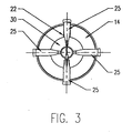
- One or more slots 22 is provided in the upper section 14 of the heater assembly 10 to support a corresponding number of compules 25 of photocurable restorative material. Once the upper section 14 is heated it serves as a heat sink upon its removal from the base 12 to maintain the compules at a relatively uniform temperature over an extended time period.
- four compules 25 are shown symmetrically arranged in slots 22 positioned 90° apart from one another.
- the cover 15 is seated over the heater assembly 10 to substantially enclose the compules 25 within an enclosed space 27 to facilitate the heating of the compules 25.
- the design of the individual compules 25 does not form a part of the present invention. Different compule designs are available commercially for conventional use with different dispensers.
- the compules 25 are generally affixed to the end of the dispenser and have a contoured shape with an open ended tip 29 at the distal end thereof which lies at an appropriate angle from the central axis of the compule 25.
- Photocurable material is discharged into a dental cavity from the compules 25 as shown in Figure 3 and Figure 7 by attachment of each compule to a conventional dispensing syringe.
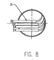
- the heating assembly may be used to heat a combination compute syringe dispenser 31. Such combination compule syringe dispenser(s) 31 are presently commercially available.
- the upper section 14 of the heating assembly contains an annular channel 30 for receiving the tips 29 of the compules 25.
- Figures 7 and 8 show alternate arrangements to accommodate different compule/syringe designs.
- the reactive monomer in the photocurable material converts to polymer in a substantially linear relationship over a temperature range extending from a refrigerated temperature of -6.6°C (20° F) to an elevated temperature of 65,6°C (150°F ).
- a small amount of material was expressed between two mylar strips and conditioned for a minimum of 30 minutes at selected pre-set temperature values.
- a conventional dental light curing unit was also placed in each temperature environment.
- Figure 4 shows the relationship of monomer conversion to pre-cure temperature.
- Figures 5 and 6 show the effect of temperature on viscosity with viscosity measured by the thickness variation of the material, i.e., a less viscous material will have less thickness.
- Figures 5 and 6 validate the concept of the present invention that an increase in the temperature of photocurable materials above ambient temperature and particularly above 37,8°C (100° F) and optimally at 54,4°C (°130 F) prior to clinical usage unexpectedly enhances cure.
Abstract
Description
- This invention relates to a method and heating assembly for pre-heating dental material(s) prior to clinical usage and more particularly to a method and device for pre-heating compule(s) of dental material to an elevated temperature, above ambient, prior to clinical usage.
- DE 1909857;
EP 0 895 772 andEP 0 826 420 disclose heating assemblies. - In accordance with the present invention it has been discovered that many dental materials have properties which can be enhanced by being preheated just prior to clinical usage. Examples of such dental materials include etching agents, bleaching compositions, dental cements, impression materials and more particularly photocurable dental restorative materials. All such dental materials can be dispensed through a dispensing device such as a syringe. Presently, it has become conventional to package dental material(s) particularly dental restorative materials in unit dosage within a removable section hereafter called a "compule" of the dispensing device. The use of a dispenser facilitates the handling and discharge of the dental material(s) from the compule directly into the patient's mouth.
- Photocurable dental restorative materials have become popular as a replacement for silver amalgams and have the advantage of matching the tooth color and being adjustable in the dental cavity for contour as well as shape before curing. Photocurable dental materials are composite compositions of unreactive monomer(s) and filler formulated to be polymerized by photochemical action upon exposure to light. In general photocurable restorative materials are typically formulated for dental usage as a paste and will polymerize upon the application of light in the 300-500 nanometer range. The concentration of filler in the composite is adjusted as high as possible to maximize strength, typically between 75-90% of the composition. The higher the filler concentration the more viscous and the more difficult the material is to dispense, handle and polymerize. Moreover, it is conventional for many dentists to refrigerate compules containing the photocurable dental restorative material prior to clinical use. The purpose of cold storage is to slow down the natural generation of free radicals within the material and thereby extend the useful life of the material. However, the viscosity of the composite is also subject to temperature and the colder the temperature the more viscous the material becomes. The ability of the photocurable material to flow and adapt to the intricacies of a dental cavity preparation will be compromised if sufficient time is not given to restore the temperature of the refrigerated composite back to room temperature.
- It has been discovered in accordance with the present invention that when compules of photocurable composite materials are pre-heated to an elevated temperature above ambient immediately prior to clinical usage the degree of conversion i.e., the percentage of unreacted monomer converted to polymer within the cavity preparation is substantially increased. In addition, by pre-heating the compules of photocurable composite materials its viscosity is substantially reduced permitting yet higher filler loading(s) in the composite material and enabling the restorative material expressed from the compule to adapt better to the walls of the cavity preparation and to the intricacies of the cavity preparation.
- The principle advantages of preheating compules of photocurable material(s) prior to clinical usage are as follows:
- (1) Improved monomer conversion,
- (2) Improved material hardness,
- (3) Improved wear resistance,
- (4) Improved color stability, and
- (5) Improved strength.
- Some or all of the same advantages apply when preheating dental material other than photocurable restorative material(s) prior to clinical usage. For example heating a bleaching composition containing a peroxide bleaching agent will be more active at higher temperatures. Thus the performance of many dental material(s) heated prior to clinical usage will be improved and their application time decreased in accordance with the present invention.
- The method of the present invention for enhancing the cure of photocurable dental restorative composite materials containing unreactive monomer(s) and filler upon exposure to light radiation broadly comprises the step of preheating the photocurable dental restorative composite(s) to an elevated temperature above ambient prior to said exposure to light radiation during clinical usage.
- The heating assembly of the present invention for heating dental materials prior to clinical usage comprises a base, an upper section removably mounted on the base for supporting one or more compules containing photocurable dental restorative composite material(s), with the upper section being composed of a conductive material and with the base forming a housing for a thermostat, a power connection for electrically connecting the thermostat to a source of power and a heating element for uniformity heating said upper section to an elevated temperature preset by said thermostat for preheating said compules to said elevated temperature.
- Other features and advantages of the present invention will become apparent from the following detailed description of the invention when read in conjunction with the accompanying drawings of which:
- Figure 1 is a perspective view of the heater assembly of the present invention;
- Figure 2 is a cross sectional view of the heater assembly of Figure 1,
- Figure 3 is a top view of the heater assembly of Figure 1 with the cover removed,
- Figure 4 is a graph showing the relationship between pre-cure temperature and percentage of monomer conversion into polymer;
- Figure 5 is another graph showing the effect of different temperatures on the viscosity of a typical composite dental resin material before cure with viscosity differences shown by measuring the average thickness variation of the material at each temperature;
- Figure 6 is yet another graph similar to Figure 5 which shows that the relationship of temperature and the viscosity (measured by thickness variation) of the pre-cured dental material is non-linear;
- Figure 7 shows an alternative compule arrangement for the heater assembly of Figure 1; and
- Figure 8 shows yet another alternative compule arrangement using small syringe compules with the heater assembly of the present invention.
- The
preferred heater assembly 10 of the present invention is shown in Figures 1,2,3,7 and 8 and comprises abase 12 having a removableupper section 14 mounted on thebase 12 and aremovable cover 15. Theheater assembly 10 may be of any suitable geometry and size. In the embodiment of Figure 1 thebase 12 is cylindrical. Thebase 12 has acavity 13 in which athermostat 16 and apower connection 17 is mounted. Thebase 12 supports the removableupper section 14. Thebase 12 may be composed from any suitable material such as plastic or metal. Thepower connection 17 extends from thecavity 13 in thebase 12 to theperiphery 18 of thebase 12 for electrically connecting thethermostat 16 to a suitable external source of electrical power (not shown). Although not shown theheater assembly 10 may also be operated from a rechargeable battery. Thethermostat 16 may also be connected in circuit with a suitable visible light source (not shown) to provide a visual indication that the thermostat is operational and the unit has reached operating temperature. - The
thermostat 16 is electrically connected to aheating element 20 to form an electrical resistive heater for heating theupper section 14 to a controlled temperature. Theheating element 20 is a conductive material in the form of a filamentary wire or flat conductor of graphite, tungsten, copper or other suitable conductive material in a serpentine or other geometrical arrangement to form a series electrical path with thethermostat 16. Theheating element 20 is embedded in a plastic, ceramic or rubber compound so as to form a flat surface which is connected to a conductiveflat plate 21 upon which theupper section 14 rests. Theflat plate 21 is removably affixed to thebase 12 and provides a planar surface for uniformity heating theupper section 14 of theheating assembly 10. Thethermostat 16 andheating element 20 are commercially available as a single unit. Thethermostat 16 controls the temperature of theheating element 20. Any conventional type of thermostat may be used for this purpose and is preferably preadjusted to bring the temperature of theheating element 20 to a suitable elevated temperature above ambient room temperature but preferably between 100°F and 140°F. The optimum temperature setting of theheating element 20 is about 130°F for photocurable dental materials. It could be higher for bleaching or other dental materials applied to the enamel. Too high a temperature would cause dental pulp damage. - The removable
upper section 14 of theheating assembly 10 is of a conductive material such as aluminum, copper, brass or stainless steel and rests upon theflat plate 21 which may be fabricated from a similar conductive material. One or more slots 22 is provided in theupper section 14 of theheater assembly 10 to support a corresponding number ofcompules 25 of photocurable restorative material. Once theupper section 14 is heated it serves as a heat sink upon its removal from thebase 12 to maintain the compules at a relatively uniform temperature over an extended time period. In the embodiment of Figure 1 fourcompules 25 are shown symmetrically arranged in slots 22 positioned 90° apart from one another. Thecover 15 is seated over theheater assembly 10 to substantially enclose thecompules 25 within anenclosed space 27 to facilitate the heating of thecompules 25. An insulatingmember 28, preferably rubber or plastic O-ring(s), surrounds theupper section 14 to enable theupper section 14 to be removed from the base 12 to a dental tray adjacent the patient at the elevated temperature to which thecompules 25 have been raised. - The design of the
individual compules 25 does not form a part of the present invention. Different compule designs are available commercially for conventional use with different dispensers. Thecompules 25 are generally affixed to the end of the dispenser and have a contoured shape with an open endedtip 29 at the distal end thereof which lies at an appropriate angle from the central axis of thecompule 25. Photocurable material is discharged into a dental cavity from thecompules 25 as shown in Figure 3 and Figure 7 by attachment of each compule to a conventional dispensing syringe. Alternatively as shown in Figure 8 the heating assembly may be used to heat a combinationcompute syringe dispenser 31. Such combination compule syringe dispenser(s) 31 are presently commercially available. Theupper section 14 of the heating assembly contains anannular channel 30 for receiving thetips 29 of thecompules 25. Figures 7 and 8 show alternate arrangements to accommodate different compule/syringe designs. - In accordance with the present invention it was discovered that the reactive monomer in the photocurable material converts to polymer in a substantially linear relationship over a temperature range extending from a refrigerated temperature of -6.6°C (20° F) to an elevated temperature of 65,6°C (150°F ). This was substantiated by the graphically presented data in Figure 4 using a commercially common photo-activated composite identified as Herculite XRV, shade A2, manufactured by Kerr/Sybron of Orange California. A small amount of material was expressed between two mylar strips and conditioned for a minimum of 30 minutes at selected pre-set temperature values. A conventional dental light curing unit was also placed in each temperature environment. While in this environment the test specimen was exposed to a controlled intensity (500mW/cm2) of curing light for 60 seconds. Following exposure the specimen was stored in the dark for 24 hours. The extent of monomer conversion was then determined by using an infrared spectrometer (FTIR) and standardized methods of statistical analysis. Figure 4 shows the relationship of monomer conversion to pre-cure temperature. Figures 5 and 6 show the effect of temperature on viscosity with viscosity measured by the thickness variation of the material, i.e., a less viscous material will have less thickness. Figures 5 and 6 validate the concept of the present invention that an increase in the temperature of photocurable materials above ambient temperature and particularly above 37,8°C (100° F) and optimally at 54,4°C (°130 F) prior to clinical usage unexpectedly enhances cure.
Claims (10)
- A method for enhancing the cure of a photocurable dental restorative composite material containing unreacted monomer(s) and filler upon its exposure to light radiation comprising the steps of:storing said dental restorative composite material in a container, andpreheating tne container housing said photocurable dental restoration composite material to raise the temperature of said dental restorative composite material to an elevated temperature above ambient prior to use.
- A method as defined in claim 1 wherein said container housing said dental restorative composite material comprises a compule.
- A method as defined in claim 1 or 2 wherein said compule is preheated to a preset temperature between about 37.8° C (100° F) to 60° C (140° F).
- A method as defined in claim 3 wherein said compule is preheated to a preset temperature of about 54.4°C (130° F).
- A heating assembly for preheating one or more dental compules containing dental material prior to clinical usage comprising a base (12) and an upper section (14) composed of a conductive material,
said upper section (14) being removably mounted on said base (12) and having one or more slots (22) to accommodate each of one or more of said dental compules (25), said upper section functioning as a heat sink for each of said compules (25) and being capable of maintaining said compules at a relatively uniform temperature over an extended perior of time,
said base (12) comprising a thermostat (16), a power connection(17) for electrically connecting the thermostat to a source of power, a heating element (20) for uniformly heating the base (12) and a conductive material (21) in engagement with said heating element (20) having a substantially planar surface upon which said removable upper section (14) rests to cause the temperature of the upper section (14) when mounted thereon to rise to an elevated temperature according to said thermostat (16) and to uniformly heat each compute (25)in each of said slots (22) and, in turn, the dental material in each compule (25) respectively to said elevated temperature. - A heating assembly as defined in claim 5 wherein said heating element (20) in said base is in the form of a filamentary wire or flat conductor connected to the thermostat (16) to form an electrical resistive heater.
- A heating assembly as defined in any of claims 5 or 6 wherein said upper section (14) is composed of a material selected from the class consisting of aluminum, copper, brass and stainless steel.
- A heating assembly as defined in any of claims 5 to 7 further comprising an insulating member (28) surrounding said upper section (14) which enables said upper section (14) to be removed from said base (12) even at said elevated temperature so that said compules (25) may be moved when necessary to a dental tray at said elevated temperature.
- A heating assembly as defined in any of the claims 5 to 8 wherein each of said compules (25) is incorporated in a dispensing device as a single unit to be heated by said heating assembly.
- A heating assembly as defined in claim 9 wherein said dispensing device is a syringe dispenser (31) of dental material.
Priority Applications (4)
| Application Number | Priority Date | Filing Date | Title |
|---|---|---|---|
| DE60029752T DE60029752T2 (en) | 2000-05-03 | 2000-05-03 | Method and heating device for preheating dental materials |
| EP00109430A EP1151728B1 (en) | 2000-05-03 | 2000-05-03 | Method and heating assembly for preheating dental materials |
| DK00109430T DK1151728T3 (en) | 2000-05-03 | 2000-05-03 | Method and heating device for preheating dental materials |
| AT00109430T ATE334637T1 (en) | 2000-05-03 | 2000-05-03 | METHOD AND HEATING DEVICE FOR PREHEATING DENTAL MATERIALS |
Applications Claiming Priority (1)
| Application Number | Priority Date | Filing Date | Title |
|---|---|---|---|
| EP00109430A EP1151728B1 (en) | 2000-05-03 | 2000-05-03 | Method and heating assembly for preheating dental materials |
Publications (2)
| Publication Number | Publication Date |
|---|---|
| EP1151728A1 EP1151728A1 (en) | 2001-11-07 |
| EP1151728B1 true EP1151728B1 (en) | 2006-08-02 |
Family
ID=8168612
Family Applications (1)
| Application Number | Title | Priority Date | Filing Date |
|---|---|---|---|
| EP00109430A Expired - Lifetime EP1151728B1 (en) | 2000-05-03 | 2000-05-03 | Method and heating assembly for preheating dental materials |
Country Status (4)
| Country | Link |
|---|---|
| EP (1) | EP1151728B1 (en) |
| AT (1) | ATE334637T1 (en) |
| DE (1) | DE60029752T2 (en) |
| DK (1) | DK1151728T3 (en) |
Cited By (6)
| Publication number | Priority date | Publication date | Assignee | Title |
|---|---|---|---|---|
| US7748070B2 (en) | 2003-09-09 | 2010-07-06 | The Procter & Gamble Company | Electric toothbrush comprising an electrically powered element |
| US7845039B2 (en) | 2003-09-09 | 2010-12-07 | The Procter & Gamble Company | Toothbrush with severable electrical connections |
| US8308722B2 (en) | 1998-12-14 | 2012-11-13 | Medwaves, Inc. | Hollow conductive coaxial cable for radio frequency based tissue ablation system |
| DE102018114690A1 (en) | 2018-06-19 | 2019-12-19 | Voco Gmbh | Thermally effective dental composite composition |
| DE102018126140A1 (en) | 2018-10-22 | 2020-04-23 | Voco Gmbh | Device with a thermochromic temperature indicator for the absorption, heating and application of dental materials |
| DE102021103980A1 (en) | 2021-02-19 | 2022-08-25 | Universität Rostock, Körperschaft des öffentlichen Rechts | Arrangement for receiving and/or applying a dental composite |
Families Citing this family (1)
| Publication number | Priority date | Publication date | Assignee | Title |
|---|---|---|---|---|
| EP4031062B8 (en) * | 2019-09-19 | 2024-04-10 | Solventum Intellectual Properties Company | A device for heating a dental material |
Family Cites Families (4)
| Publication number | Priority date | Publication date | Assignee | Title |
|---|---|---|---|---|
| DE1909857A1 (en) * | 1969-02-27 | 1970-09-10 | Konrad Ziesling | Electric cooking process |
| FR2044308A5 (en) * | 1969-05-16 | 1971-02-19 | Bardonnet Gabriel | |
| FR2752754B1 (en) * | 1996-08-27 | 1998-10-23 | Pierron Entreprise | ELECTRIC HEATING DEVICE FOR LABORATORY GLASSWARE |
| EP0895772A1 (en) * | 1997-08-07 | 1999-02-10 | Seb S.A. | Heating device for a feeding bottle with a metallic bottom |
-
2000
- 2000-05-03 AT AT00109430T patent/ATE334637T1/en not_active IP Right Cessation
- 2000-05-03 EP EP00109430A patent/EP1151728B1/en not_active Expired - Lifetime
- 2000-05-03 DE DE60029752T patent/DE60029752T2/en not_active Expired - Lifetime
- 2000-05-03 DK DK00109430T patent/DK1151728T3/en active
Cited By (7)
| Publication number | Priority date | Publication date | Assignee | Title |
|---|---|---|---|---|
| US8308722B2 (en) | 1998-12-14 | 2012-11-13 | Medwaves, Inc. | Hollow conductive coaxial cable for radio frequency based tissue ablation system |
| US7748070B2 (en) | 2003-09-09 | 2010-07-06 | The Procter & Gamble Company | Electric toothbrush comprising an electrically powered element |
| US7845039B2 (en) | 2003-09-09 | 2010-12-07 | The Procter & Gamble Company | Toothbrush with severable electrical connections |
| DE102018114690A1 (en) | 2018-06-19 | 2019-12-19 | Voco Gmbh | Thermally effective dental composite composition |
| DE102018126140A1 (en) | 2018-10-22 | 2020-04-23 | Voco Gmbh | Device with a thermochromic temperature indicator for the absorption, heating and application of dental materials |
| DE102018126140B4 (en) | 2018-10-22 | 2023-12-07 | Voco Gmbh | Device with a thermochromic temperature indicator for receiving, heating and applying dental materials |
| DE102021103980A1 (en) | 2021-02-19 | 2022-08-25 | Universität Rostock, Körperschaft des öffentlichen Rechts | Arrangement for receiving and/or applying a dental composite |
Also Published As
| Publication number | Publication date |
|---|---|
| DK1151728T3 (en) | 2006-11-27 |
| ATE334637T1 (en) | 2006-08-15 |
| DE60029752T2 (en) | 2007-08-09 |
| EP1151728A1 (en) | 2001-11-07 |
| DE60029752D1 (en) | 2006-09-14 |
Similar Documents
| Publication | Publication Date | Title |
|---|---|---|
| US6320162B1 (en) | Method for preheating dental materials | |
| US6511317B2 (en) | Device for curing photosensitive dental compositions with off-axis lens and method of curing | |
| US6755647B2 (en) | Photocuring device with axial array of light emitting diodes and method of curing | |
| US6468077B1 (en) | Compact device for curing dental compositions and method of curing | |
| US6441354B1 (en) | Microwave polymerization system for dentistry | |
| WO1999021505A1 (en) | Dental composite light curing system | |
| Peutzfeldt et al. | The effect of postcuring on quantity of remaining double bonds, mechanical properties, and in vitro wear of two resin composites | |
| Rueggeberg | State-of-the-art: dental photocuring—a review | |
| US6318996B1 (en) | Method for curing a dental composition using a light emitting diode | |
| US6089740A (en) | Multipurpose dental lamp apparatus | |
| US20060269893A1 (en) | Medical treatment apparatus and needle manufacturing method | |
| EP1151728B1 (en) | Method and heating assembly for preheating dental materials | |
| WO1999009071A1 (en) | System and method for controlling a light actuator to achieve partial polymerization | |
| Baroudi et al. | In vitro pulp chamber temperature rise from irradiation and exotherm of flowable composites | |
| Dietschi et al. | Comparative efficiency of plasma and halogen light sources on composite micro-hardness in different curing conditions | |
| JPH07255751A (en) | Dental impression tray for photosetting impression material | |
| US6254389B1 (en) | Hand-held microwave intra-oral dental system | |
| WO1992011833A1 (en) | Apparatus and method for applying gutta-percha | |
| WO1997036552A1 (en) | Apparatus and method for polymerising dental photopolymerisable compositions | |
| Danesh et al. | Polymerisation characteristics of resin composites polymerised with different curing units | |
| US6948933B2 (en) | Complex root canal plugging apparatus for dental work | |
| US7015423B2 (en) | Heating device for dental material | |
| WO1989002753A1 (en) | Apparatus for sterilizing objects, in particular dental and medical utensils | |
| US5477054A (en) | Denture curing apparatus and method | |
| Peutzfeldt | Effect of the ultrasonic insertion technique on the seating of composite inlays |
Legal Events
| Date | Code | Title | Description |
|---|---|---|---|
| PUAI | Public reference made under article 153(3) epc to a published international application that has entered the european phase |
Free format text: ORIGINAL CODE: 0009012 |
|
| AK | Designated contracting states |
Kind code of ref document: A1 Designated state(s): AT BE CH CY DE DK ES FI FR GB GR IE IT LI LU MC NL PT SE |
|
| AX | Request for extension of the european patent |
Free format text: AL;LT;LV;MK;RO;SI |
|
| 17P | Request for examination filed |
Effective date: 20020507 |
|
| AKX | Designation fees paid |
Free format text: AT BE CH CY DE DK ES FI FR GB GR IE IT LI LU MC NL PT SE |
|
| 17Q | First examination report despatched |
Effective date: 20040729 |
|
| GRAP | Despatch of communication of intention to grant a patent |
Free format text: ORIGINAL CODE: EPIDOSNIGR1 |
|
| GRAS | Grant fee paid |
Free format text: ORIGINAL CODE: EPIDOSNIGR3 |
|
| GRAA | (expected) grant |
Free format text: ORIGINAL CODE: 0009210 |
|
| AK | Designated contracting states |
Kind code of ref document: B1 Designated state(s): AT BE CH CY DE DK ES FI FR GB GR IE IT LI LU MC NL PT SE |
|
| PG25 | Lapsed in a contracting state [announced via postgrant information from national office to epo] |
Ref country code: AT Free format text: LAPSE BECAUSE OF FAILURE TO SUBMIT A TRANSLATION OF THE DESCRIPTION OR TO PAY THE FEE WITHIN THE PRESCRIBED TIME-LIMIT Effective date: 20060802 Ref country code: LI Free format text: LAPSE BECAUSE OF FAILURE TO SUBMIT A TRANSLATION OF THE DESCRIPTION OR TO PAY THE FEE WITHIN THE PRESCRIBED TIME-LIMIT Effective date: 20060802 Ref country code: FI Free format text: LAPSE BECAUSE OF FAILURE TO SUBMIT A TRANSLATION OF THE DESCRIPTION OR TO PAY THE FEE WITHIN THE PRESCRIBED TIME-LIMIT Effective date: 20060802 Ref country code: BE Free format text: LAPSE BECAUSE OF FAILURE TO SUBMIT A TRANSLATION OF THE DESCRIPTION OR TO PAY THE FEE WITHIN THE PRESCRIBED TIME-LIMIT Effective date: 20060802 Ref country code: NL Free format text: LAPSE BECAUSE OF FAILURE TO SUBMIT A TRANSLATION OF THE DESCRIPTION OR TO PAY THE FEE WITHIN THE PRESCRIBED TIME-LIMIT Effective date: 20060802 Ref country code: CH Free format text: LAPSE BECAUSE OF FAILURE TO SUBMIT A TRANSLATION OF THE DESCRIPTION OR TO PAY THE FEE WITHIN THE PRESCRIBED TIME-LIMIT Effective date: 20060802 Ref country code: IT Free format text: LAPSE BECAUSE OF FAILURE TO SUBMIT A TRANSLATION OF THE DESCRIPTION OR TO PAY THE FEE WITHIN THE PRE;WARNING: LAPSES OF ITALIAN PATENTS WITH EFFECTIVE DATE BEFORE 2007 MAY HAVE OCCURRED AT ANY TIME BEFORE 2007. THE CORRECT EFFECTIVE DATE MAY BE DIFFERENT FROM THE ONE RECORDED.SCRIBED TIME-LIMIT Effective date: 20060802 |
|
| REG | Reference to a national code |
Ref country code: GB Ref legal event code: FG4D |
|
| REG | Reference to a national code |
Ref country code: CH Ref legal event code: EP |
|
| REG | Reference to a national code |
Ref country code: IE Ref legal event code: FG4D |
|
| REF | Corresponds to: |
Ref document number: 60029752 Country of ref document: DE Date of ref document: 20060914 Kind code of ref document: P |
|
| PG25 | Lapsed in a contracting state [announced via postgrant information from national office to epo] |
Ref country code: ES Free format text: LAPSE BECAUSE OF FAILURE TO SUBMIT A TRANSLATION OF THE DESCRIPTION OR TO PAY THE FEE WITHIN THE PRESCRIBED TIME-LIMIT Effective date: 20061113 |
|
| REG | Reference to a national code |
Ref country code: SE Ref legal event code: TRGR |
|
| REG | Reference to a national code |
Ref country code: DK Ref legal event code: T3 |
|
| NLV1 | Nl: lapsed or annulled due to failure to fulfill the requirements of art. 29p and 29m of the patents act | ||
| PG25 | Lapsed in a contracting state [announced via postgrant information from national office to epo] |
Ref country code: PT Free format text: LAPSE BECAUSE OF FAILURE TO SUBMIT A TRANSLATION OF THE DESCRIPTION OR TO PAY THE FEE WITHIN THE PRESCRIBED TIME-LIMIT Effective date: 20070102 |
|
| REG | Reference to a national code |
Ref country code: CH Ref legal event code: PL |
|
| ET | Fr: translation filed | ||
| PLBE | No opposition filed within time limit |
Free format text: ORIGINAL CODE: 0009261 |
|
| STAA | Information on the status of an ep patent application or granted ep patent |
Free format text: STATUS: NO OPPOSITION FILED WITHIN TIME LIMIT |
|
| 26N | No opposition filed |
Effective date: 20070503 |
|
| PGFP | Annual fee paid to national office [announced via postgrant information from national office to epo] |
Ref country code: GB Payment date: 20070516 Year of fee payment: 8 |
|
| PG25 | Lapsed in a contracting state [announced via postgrant information from national office to epo] |
Ref country code: MC Free format text: LAPSE BECAUSE OF NON-PAYMENT OF DUE FEES Effective date: 20070531 |
|
| PG25 | Lapsed in a contracting state [announced via postgrant information from national office to epo] |
Ref country code: GR Free format text: LAPSE BECAUSE OF FAILURE TO SUBMIT A TRANSLATION OF THE DESCRIPTION OR TO PAY THE FEE WITHIN THE PRESCRIBED TIME-LIMIT Effective date: 20061103 |
|
| PG25 | Lapsed in a contracting state [announced via postgrant information from national office to epo] |
Ref country code: IE Free format text: LAPSE BECAUSE OF NON-PAYMENT OF DUE FEES Effective date: 20070503 |
|
| PGFP | Annual fee paid to national office [announced via postgrant information from national office to epo] |
Ref country code: SE Payment date: 20080530 Year of fee payment: 9 |
|
| GBPC | Gb: european patent ceased through non-payment of renewal fee |
Effective date: 20080503 |
|
| PG25 | Lapsed in a contracting state [announced via postgrant information from national office to epo] |
Ref country code: GB Free format text: LAPSE BECAUSE OF NON-PAYMENT OF DUE FEES Effective date: 20080503 |
|
| PG25 | Lapsed in a contracting state [announced via postgrant information from national office to epo] |
Ref country code: LU Free format text: LAPSE BECAUSE OF NON-PAYMENT OF DUE FEES Effective date: 20070503 Ref country code: CY Free format text: LAPSE BECAUSE OF FAILURE TO SUBMIT A TRANSLATION OF THE DESCRIPTION OR TO PAY THE FEE WITHIN THE PRESCRIBED TIME-LIMIT Effective date: 20060802 |
|
| REG | Reference to a national code |
Ref country code: FR Ref legal event code: ST Effective date: 20100129 |
|
| PG25 | Lapsed in a contracting state [announced via postgrant information from national office to epo] |
Ref country code: FR Free format text: LAPSE BECAUSE OF NON-PAYMENT OF DUE FEES Effective date: 20090602 |
|
| PGFP | Annual fee paid to national office [announced via postgrant information from national office to epo] |
Ref country code: FR Payment date: 20080514 Year of fee payment: 9 |
|
| PG25 | Lapsed in a contracting state [announced via postgrant information from national office to epo] |
Ref country code: SE Free format text: LAPSE BECAUSE OF NON-PAYMENT OF DUE FEES Effective date: 20090504 |
|
| PGFP | Annual fee paid to national office [announced via postgrant information from national office to epo] |
Ref country code: IT Payment date: 20110516 Year of fee payment: 12 |
|
| PG25 | Lapsed in a contracting state [announced via postgrant information from national office to epo] |
Ref country code: IT Free format text: LAPSE BECAUSE OF NON-PAYMENT OF DUE FEES Effective date: 20120503 |
|
| PGFP | Annual fee paid to national office [announced via postgrant information from national office to epo] |
Ref country code: DE Payment date: 20190509 Year of fee payment: 20 Ref country code: DK Payment date: 20190509 Year of fee payment: 20 |
|
| REG | Reference to a national code |
Ref country code: DE Ref legal event code: R071 Ref document number: 60029752 Country of ref document: DE |
|
| REG | Reference to a national code |
Ref country code: DK Ref legal event code: EUP Expiry date: 20200503 |