EP1156598A2 - Orthogonal frequency division multiplexing transmit diversity system for frequency-selective fading channels - Google Patents
Orthogonal frequency division multiplexing transmit diversity system for frequency-selective fading channels Download PDFInfo
- Publication number
- EP1156598A2 EP1156598A2 EP01303929A EP01303929A EP1156598A2 EP 1156598 A2 EP1156598 A2 EP 1156598A2 EP 01303929 A EP01303929 A EP 01303929A EP 01303929 A EP01303929 A EP 01303929A EP 1156598 A2 EP1156598 A2 EP 1156598A2
- Authority
- EP
- European Patent Office
- Prior art keywords
- means adapted
- time domain
- frequency
- antenna
- signal
- Prior art date
- Legal status (The legal status is an assumption and is not a legal conclusion. Google has not performed a legal analysis and makes no representation as to the accuracy of the status listed.)
- Granted
Links
Images


Classifications
-
- H—ELECTRICITY
- H04—ELECTRIC COMMUNICATION TECHNIQUE
- H04B—TRANSMISSION
- H04B7/00—Radio transmission systems, i.e. using radiation field
- H04B7/02—Diversity systems; Multi-antenna system, i.e. transmission or reception using multiple antennas
- H04B7/04—Diversity systems; Multi-antenna system, i.e. transmission or reception using multiple antennas using two or more spaced independent antennas
- H04B7/06—Diversity systems; Multi-antenna system, i.e. transmission or reception using multiple antennas using two or more spaced independent antennas at the transmitting station
- H04B7/0613—Diversity systems; Multi-antenna system, i.e. transmission or reception using multiple antennas using two or more spaced independent antennas at the transmitting station using simultaneous transmission
-
- H—ELECTRICITY
- H04—ELECTRIC COMMUNICATION TECHNIQUE
- H04L—TRANSMISSION OF DIGITAL INFORMATION, e.g. TELEGRAPHIC COMMUNICATION
- H04L27/00—Modulated-carrier systems
- H04L27/26—Systems using multi-frequency codes
- H04L27/2601—Multicarrier modulation systems
- H04L27/2602—Signal structure
-
- H—ELECTRICITY
- H04—ELECTRIC COMMUNICATION TECHNIQUE
- H04B—TRANSMISSION
- H04B7/00—Radio transmission systems, i.e. using radiation field
- H04B7/02—Diversity systems; Multi-antenna system, i.e. transmission or reception using multiple antennas
- H04B7/04—Diversity systems; Multi-antenna system, i.e. transmission or reception using multiple antennas using two or more spaced independent antennas
- H04B7/06—Diversity systems; Multi-antenna system, i.e. transmission or reception using multiple antennas using two or more spaced independent antennas at the transmitting station
- H04B7/0613—Diversity systems; Multi-antenna system, i.e. transmission or reception using multiple antennas using two or more spaced independent antennas at the transmitting station using simultaneous transmission
- H04B7/0667—Diversity systems; Multi-antenna system, i.e. transmission or reception using multiple antennas using two or more spaced independent antennas at the transmitting station using simultaneous transmission of delayed versions of same signal
- H04B7/0669—Diversity systems; Multi-antenna system, i.e. transmission or reception using multiple antennas using two or more spaced independent antennas at the transmitting station using simultaneous transmission of delayed versions of same signal using different channel coding between antennas
-
- H—ELECTRICITY
- H04—ELECTRIC COMMUNICATION TECHNIQUE
- H04L—TRANSMISSION OF DIGITAL INFORMATION, e.g. TELEGRAPHIC COMMUNICATION
- H04L1/00—Arrangements for detecting or preventing errors in the information received
- H04L1/02—Arrangements for detecting or preventing errors in the information received by diversity reception
- H04L1/06—Arrangements for detecting or preventing errors in the information received by diversity reception using space diversity
- H04L1/0606—Space-frequency coding
-
- H—ELECTRICITY
- H04—ELECTRIC COMMUNICATION TECHNIQUE
- H04L—TRANSMISSION OF DIGITAL INFORMATION, e.g. TELEGRAPHIC COMMUNICATION
- H04L1/00—Arrangements for detecting or preventing errors in the information received
- H04L1/02—Arrangements for detecting or preventing errors in the information received by diversity reception
- H04L1/06—Arrangements for detecting or preventing errors in the information received by diversity reception using space diversity
- H04L1/0618—Space-time coding
- H04L1/0637—Properties of the code
- H04L1/0656—Cyclotomic systems, e.g. Bell Labs Layered Space-Time [BLAST]
-
- H—ELECTRICITY
- H04—ELECTRIC COMMUNICATION TECHNIQUE
- H04L—TRANSMISSION OF DIGITAL INFORMATION, e.g. TELEGRAPHIC COMMUNICATION
- H04L27/00—Modulated-carrier systems
- H04L27/26—Systems using multi-frequency codes
- H04L27/2601—Multicarrier modulation systems
- H04L27/2626—Arrangements specific to the transmitter only
- H04L27/2627—Modulators
- H04L27/2634—Inverse fast Fourier transform [IFFT] or inverse discrete Fourier transform [IDFT] modulators in combination with other circuits for modulation
- H04L27/2636—Inverse fast Fourier transform [IFFT] or inverse discrete Fourier transform [IDFT] modulators in combination with other circuits for modulation with FFT or DFT modulators, e.g. standard single-carrier frequency-division multiple access [SC-FDMA] transmitter or DFT spread orthogonal frequency division multiplexing [DFT-SOFDM]
-
- H—ELECTRICITY
- H04—ELECTRIC COMMUNICATION TECHNIQUE
- H04L—TRANSMISSION OF DIGITAL INFORMATION, e.g. TELEGRAPHIC COMMUNICATION
- H04L27/00—Modulated-carrier systems
- H04L27/26—Systems using multi-frequency codes
- H04L27/2601—Multicarrier modulation systems
- H04L27/2602—Signal structure
- H04L27/2605—Symbol extensions, e.g. Zero Tail, Unique Word [UW]
- H04L27/2607—Cyclic extensions
-
- H—ELECTRICITY
- H04—ELECTRIC COMMUNICATION TECHNIQUE
- H04L—TRANSMISSION OF DIGITAL INFORMATION, e.g. TELEGRAPHIC COMMUNICATION
- H04L27/00—Modulated-carrier systems
- H04L27/26—Systems using multi-frequency codes
- H04L27/2601—Multicarrier modulation systems
- H04L27/2626—Arrangements specific to the transmitter only
Definitions
- This invention relates to wireless communications and, more particularly, to orthogonal frequency division multiplexing (OFDM) transmission systems.
- OFDM orthogonal frequency division multiplexing
- space-time block coding arrangements in the same spirit as the Alamouti arrangement can also result in rate loss when the number of transmit antennas is greater than two (2). See for example, an article authored by V. Tarokh et al. entitled "Space-time block codes from orthogonal designs", IEEE Transactions on Information Theory, Vol. 45, pp. 1456-1467, July 1999, for such space-time block coding.
- OFDM orthogonal frequency division multiplexing
- reduced complexity in the implementation is realized by employing a reverse order complex conjugate and a reverse order, reverse sign (-) complex conjugate and by judicious selection of the processed data signals in order to transmit the appropriate ones of the signals during the first and second OFDM intervals. Again, if the channel remains constant over the two OFDM intervals, diversity combination is realized for each frequency subchannel.
- antenna-group hopping is employed in conjunction with pairing in time of the OFDM frequency subchannel signals to realize increased transmit diversity without rate loss.
- FIG. 1A graphically illustrates the pairing of signals in time for use in an embodiment of the invention in transmitting from a first antenna, antenna 0, in an OFDM transmit diversity system. Specifically, shown are signal components x 0 (0) and - x * 1 (0) along the vertical time axis prior to their inverse fast Fourier transform (IFFT) and where the * denotes the complex conjugate.
- IFFT inverse fast Fourier transform
- FIG. 1B graphically illustrates the pairing of signals in time for use in an embodiment of the invention in transmitting from a second antenna, antenna 1, in an OFDM transmit diversity system. Specifically, shown are signal components x 1 (0) and x * 0 (0) along the vertical time axis prior to their inverse fast Fourier transform (IFFT and where the * denotes the complex conjugate.
- IFFT inverse fast Fourier transform
- the signal pairing in a first OFDM interval, is such that signal component x 0 (0) is transmitted from antenna 0 and signal x 1 (0) is transmitted from antenna 1, and in a second OFDM interval, the signal pairing is such that signal component - x * 1 (0) is transmitted from antenna 0 and signal component x * 0 (0) is transmitted from antenna 1.
- the * denotes the complex conjugate of the signal.
- FIG. 2 shows, in simplified block diagram form, details of an embodiment of the invention.
- signal X 0 is a digital signal that has already been encoded and modulated, e.g., using phase shift keying (PSK), quadrature amplitude modulation (QAM) or the like.
- IFFT unit 201 obtains the inverse fast Fourier transform of signal X 0 , in well known fashion, and yields Y 0 .
- Y 0 is supplied to a first input of controllable selector 205.
- N length signal vector X 1 [ x 1 (0), x 1 (1), ⁇ , x 1 ( N - 1)] also to be transmitted is supplied to inverse fast Fourier transform (IFFT) unit 203, and to reverse sign (-) complex conjugate unit 204.
- IFFT inverse fast Fourier transform
- signal X 1 is also a digital signal that has already been encoded and modulated, e.g., using PSK, QAM or the like.
- IFFT unit 203 obtains the inverse fast Fourier transform of signal X 1 , in well known fashion, and yields Y 1 .
- Y 1 is supplied to a first input of controllable selector 206.
- X * 0 [ x * 0 (0), x * 0 (1), ⁇ , x * 0 ( N - 1)]. Again, where "*" indicates complex conjugate.
- signal X * 0 to be transmitted is supplied to inverse fast Fourier transform (IFFT) unit 207.
- Y ' 0 is supplied to a second input of controllable selector 206.
- signal - X * 1 to be transmitted is supplied to inverse fast Fourier transform (IFFT) unit 208.
- Y ' 1 is supplied to a second input of controllable selector 205.
- signals X 0 , X 1 , X * 0 , and - X * 1 are frequency domain signals
- Y 0 , Y 1 , Y ' 0 , and Y ' 1 are time domain signals.
- Controllable selector 205 under control of select input 217, supplies Y 0 during a first, e.g., an even, OFDM interval and Y ' 1 during a second, e.g., an odd, OFDM interval, as an output which is supplied to cyclic prefix unit 209.
- cyclic prefix unit 209 prepends a cyclic prefix to each OFDM interval, i.e., each symbol period.
- the cyclic prefix is used to compensate for the dispersion introduced by the channel response and by a pulse shaping filter (not shown) used in the transmitter. Note that the cyclic prefix is added only for those tones used in an OFDM transmitter.
- a cyclic prefix is added for all of the available orthogonal tones. However, if the transmitter were to be used in a mobile unit using only a single OFDM tone, then the cyclic prefix uses only the particular single tone being used by the mobile unit. Then, the prepended Y 0 or Y ' 1 signal is converted to analog form via digital-to-analog (D/A) converter 210 and supplied to RF transmitter 211 for transmission via antenna 212, i.e., antenna 0. Note that RF transmitter 211 performs a conventional baseband-to-passband conversion of the OFDM signal for transmission.
- D/A digital-to-analog
- controllable selector 206 under control of select input 218, supplies Y 1 during a first, e.g., an even, OFDM interval and Y ' 0 during a second, e.g., an odd, OFDM interval, as an output to cyclic prefix unit 213.
- cyclic prefix unit 213 prepends a cyclic prefix to each OFDM interval, i.e., each symbol period.
- the cyclic prefix is used to compensate for the dispersion introduced by the channel response and by a pulse shaping filter (not shown) used in the transmitter. Note that the cyclic prefix is added only for those tones used in an OFDM transmitter.
- the instant transmitter is primarily intended for use in a base station, a cyclic prefix is added for all of the available orthogonal tones. However, if the transmitter were to be used in a mobile unit using only a single OFDM tone, then the cyclic prefix uses only the particular single tone being used by the mobile unit. Then, the prepended Y 1 or Y ' 0 signal is converted to analog form via digital-to-analog (D/A) converter 214 and supplied to RF transmitter 215 for transmission via antenna 216, i.e., antenna 1.
- D/A digital-to-analog
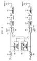
- FIG. 3 shows, in simplified block diagram form, details of a reduced complexity implement of an OFDM transmit diversity system in accordance with the invention.
- IFFT inverse fast Fourier transform
- Y 0 is supplied to a first input of controllable selector 302 and to reverse order complex conjugate unit 303.
- signal vector X 0 is a digital signal that has already been encoded and modulated, e.g., using PSK, QAM or the like.
- IFFT inverse fast Fourier transform
- Y 1 is supplied to a first input of controllable selector 305 and to reverse order, reverse sign (-) complex conjugate unit 306.
- signal vector X 1 is also a digital signal that has already been encoded and modulated, e.g., using PSK, QAM or the like.
- y ' 0 (1) y * 0 ( N - 1)
- y * 0 ( N - 1) y * 0 (1).
- Y ' 0 is supplied to a second input of controllable selector 305.
- controllable selector 305 is controlled via a signal supplied to control input 314 to select as an output, either a signal supplied to its first input or a signal supplied to its second input, namely, either Y 1 or Y ' 0 , respectively.
- y ' 1 (1) -y * 1 ( N -1)
- ⁇ , y ' 1 ( N - 1) - y * 1 (1).
- controllable selector 302 is also controlled via a signal supplied to control input 313 to select as an output, either a signal supplied to its first input or a signal supplied to its second input, namely, either Y 0 or Y ' 1 , respectively.
- An output from controllable selector 302 is supplied to cyclic prefix unit 307, which prepends a cyclic prefix to each OFDM interval, i.e., each symbol period.
- the cyclic prefix is used to compensate for the dispersion introduced by the channel response and by a pulse shaping filter (not shown) used in the transmitter. Note that the cyclic prefix is added only for those tones used in an OFDM transmitter. Since the instant transmitter is primarily intended for use in a base station, a cyclic prefix is added for all of the available orthogonal tones. However, if the transmitter were to be used in a mobile unit using only a single OFDM tone, then the cyclic prefix uses only the particular single tone being used by the mobile unit. Then, the prepended Y 0 or Y ' 1 signal is converted to analog form via digital-to-analog (D/A) converter 308 and supplied to RF transmitter 309 for transmission via antenna 310, i.e., antenna 0.
- cyclic prefix unit 311 which prepends a cyclic prefix to each OFDM interval, i.e., each symbol period.
- the cyclic prefix is used to compensate for the dispersion introduced by the channel response and by a pulse shaping filter (not shown) used in the transmitter.
- the cyclic prefix is added only for those tones used in an OFDM transmitter. Since the instant transmitter is primarily intended for use in a base station, a cyclic prefix is added for all of the available orthogonal tones. However, if the transmitter were to be used in a mobile unit using only a single OFDM tone, then the cyclic prefix uses only the particular single tone being used by the mobile unit.
- the prepended Y 1 or Y ' 0 signal is converted to analog form via digital-to-analog (D/A) converter 312 and supplied to RF transmitter 313 for transmission via antenna 314, i.e., antenna 1.
- D/A digital-to-analog
- controllable selectors 302 and 305 select signal vectors Y 0 and Y 1 , respectively
- second, e.g., odd, OFDM intervals controllable selectors select signal vectors Y ' 1 , and Y ' 0 , respectively. Therefore, in the first OFDM intervals, a signal vector version of Y 0 after the cyclic prefix is prepended and then D/A converted is supplied for transmission to antenna (0) 310 and a signal vector version of Y 1 after the cyclic prefix is prepended and then D/A converted is supplied for transmission to antenna (1) 314.
- a signal vector version of Y ' 1 after the cyclic prefix is prepended and then D/A converted is supplied for transmission to antenna (0) 310 and a signal vector version of Y ' 0 after the cyclic prefix is prepended and then D/A converted is supplied for transmission to antenna (1) 314.
- more than two transmit antennas are advantageously employed to realize the transmit diversity.
- two of the antennas are grouped together and use the signal pattern shown in FIGs. 1A and 1B. It is noted that the grouping pattern, i.e., the selection of antennas for each frequency subchannel may vary.
- frequency subchannel is referred to as just “subchannel”.
- FIG. 4A graphically illustrates the pairing of signals in time for use in an embodiment of the invention in transmitting from a first antenna, in this example, antenna 0, in an antenna-group hopping OFDM transmit diversity system.
- a first OFDM time interval a first subchannel includes signal component x 0 (0); a second subchannel includes a zero (0); a third subchannel includes signal component x 0 (2); a fourth subchannel includes a zero (0); etc.
- the first subchannel includes signal component - x * 1 (0); the second subchannel includes a zero (0); the third subchannel includes signal component - x * 1 (2) ; a fourth subchannel includes a zero (0); etc.
- FIG. 4B graphically illustrates the pairing of signals in time for use in an embodiment of the invention in transmitting from a second antenna in an antenna-group hopping OFDM transmit diversity system.
- a first OFDM time interval a first subchannel includes signal component x 1 (0); a second subchannel includes a zero (0); a third subchannel includes a zero (0); a fourth subchannel includes signal component x 0 (3); etc.
- the first subchannel includes signal component x * 0 (0); the second subchannel includes a zero (0); the third subchannel includes a zero (0); a fourth subchannel includes signal component - x * 1 (3); etc.
- FIG. 4C graphically illustrates the pairing of signals in time for use in an embodiment of the invention in transmitting from a third antenna in an antenna-group hopping OFDM transmit diversity system.
- a first OFDM time interval a first subchannel includes a zero (0); a second subchannel includes signal component x 0 (1); a third subchannel includes signal component x 1 (2); a fourth subchannel includes a zero (0); etc.
- the first subchannel includes a zero (0); the second subchannel includes signal component - x * 1 (1); the third subchannel includes signal component x * 0 (2); a fourth subchannel includes a zero (0); etc.
- FIG. 4D graphically illustrates the pairing of signals in time for use in an embodiment of the invention in transmitting from a fourth antenna in an antenna-group hopping OFDM transmit diversity system.
- a first OFDM time interval a first subchannel includes a zero (0); a second subchannel includes signal component x 1 (1); a third subchannel includes a zero (0); a fourth subchannel includes signal component x 1 (3); etc.
- the first subchannel includes a zero (0); the second subchannel includes signal component x * 0 (1); the third subchannel includes a zero (0); a fourth subchannel includes signal component x * 0 (3) ; etc.
- the signal components are paired in time on each subchannel.
- the grouping of the antennas varies from subchannel to subchannel. On a first subchannel antennas 0 and 1 are grouped together; on a second subchannel, antennas 2 and 3 are grouped together; on a third subchannel antennas 0 and 2 are grouped together; on a fourth subchannel antennas 1 and 3 are grouped together; and so on.
- FIG. 5 shows, in simplified block diagram form, details of an embodiment of the invention for use in effecting antenna-group hopping in an OFDM transmit diversity system.
- N length signal vector X 1 [ x 1 (0), x 1 (1), ⁇ , x 1 ( N - 1)] also to be transmitted is also supplied to signal and select processor, and distributor 501.
- signals are generated as represented by X ' 0 , X ' 1 , X ' 2 , X ' 3 , X ' 4 , X ' 5 , X ' 6 and X ' 7 . As shown in FIG.
- X ' 0 [ x 0 (0),0, x 0 (2),0, x 0 (4),0, x 0 (6),0, ⁇ ];
- X ' 1 [- x * 1 (0),0,- x * 1 (2),0,- x * 1 (4),0,- x * 1 (6),0, ⁇ ];
- X ' 2 [ x 1 (0),0,0, x 0 (3), x 1 (4),0,0, x 0 (7), ⁇ ];
- X ' 3 [ x * 0 (0),0,0,- x * 1 (3), x * 0 (4),0,0,- x * 1 (7) ⁇ ];
- X ' 4 [0, x 0 (1), x 1 (2),0,0, x 0 (5), x 1 (6),0, ⁇ ];
- X ' 5 [0,- x * 1 (1), x * 0 (2)
- Z ' 0 is supplied to a first input of controllable selector 503.
- Z ' 1 is supplied to a second input of controllable selector 503.
- Controllable selector 503 is responsive to control signals supplied to terminal 515, from select bus 514 generated by signal and select processor, and distributor 501, to realize selection of the signal components during alternate OFDM time intervals, e.g., during even and odd intervals.
- controllable selector 503 The output from controllable selector 503 is supplied to cyclic prefix unit 516 that prepends a cyclic prefix to each OFDM interval, i.e., each symbol period, as described above. Then, the prepended Z ' 0 or Z ' 1 signal is converted to analog form via digital-to-analog (D/A) converter 517 and supplied to RF transmitter 518 for transmission via antenna 519, i.e., antenna 0.
- D/A digital-to-analog
- Z ' 2 is supplied to a first input of controllable selector 506.
- Z ' 3 is supplied to a second input of controllable selector 506.
- Controllable selector 506 is responsive to control signals supplied to terminal 520, from select bus 514 generated by signal and select processor, and distributor 501, to realize selection of the signal components during alternate OFDM time intervals, e.g., during even and odd intervals.
- controllable selector 506 is supplied to cyclic prefix unit 521 that prepends a cyclic prefix to each OFDM interval, i.e., each symbol period, as described above. Then, the prepended Z ' 2 or Z ' 3 signal is converted to analog form via digital-to-analog (D/A) converter 522 and supplied to RF transmitter 523 for transmission via antenna 524, i.e., antenna 1.
- D/A digital-to-analog
- Z ' 4 is supplied to a first input of controllable selector 509.
- Z ' 5 is supplied to a second input of controllable selector 509.
- Controllable selector 509 is responsive to control signals supplied to terminal 525, from select bus 514 generated by signal and select processor, and distributor 501, to realize selection of the signal components during alternate OFDM time intervals, e.g., during even and odd intervals.
- controllable selector 509 The output from controllable selector 509 is supplied to cyclic prefix unit 526 that prepends a cyclic prefix to each OFDM interval, i.e., each symbol period, as described above. Then, the prepended Z ' 4 or Z ' 5 signal is converted to analog form via digital-to-analog (D/A) converter 527 and supplied to RF transmitter 528 for transmission via antenna 529, i.e., antenna 2.
- D/A digital-to-analog
- Z ' 6 is supplied to a first input of controllable selector 512.
- Z ' 7 is supplied to a second input of controllable selector 512.
- Controllable selector 512 is responsive to control signals supplied to terminal 530, from select bus 514 generated by signal and select processor, and distributor 501, to realize selection of the signal components during alternate OFDM time intervals, e.g., during even and odd intervals.
- controllable selector 512 is supplied to cyclic prefix unit 531 that prepends a cyclic prefix to each OFDM interval, i.e., each symbol period, as described above. Then, the prepended Z ' 6 or Z ' 7 signal is converted to analog form via digital-to-analog (D/A) converter 532 and supplied to RF transmitter 533 for transmission via antenna 534, i.e., antenna 3.
- D/A digital-to-analog
- antenna grouping can be in clusters of tones, instead of tone-by-tone.
- other special antenna grouping patterns are also readily realizable without departing from the spirit and scope of the invention.
Abstract
Description
- This invention relates to wireless communications and, more particularly, to orthogonal frequency division multiplexing (OFDM) transmission systems.
- Arrangements are know for realizing transmit diversity for flat-fading transmission channels in wireless communications systems. One such prior known system of particular interest is described in an article authored by S. M. Alamouti an entitled "A Simple Transmit Diversity Technique for Wireless Communications", IEEE Journal On Select Areas In Communications, Vol. 16, No. 8, pp. 1451-1458, October 1998. Also see PCT published patent application WO9914871A1 issued March 25, 1999 to Alamouti et al. However, the Alamouti arrangement cannot be directly applied to frequency-selective fading channels. Moreover, the Alamouti arrangement leads to transmission rate loss when more than two (2) transmit antennas are employed. Additionally, other space-time block coding arrangements in the same spirit as the Alamouti arrangement can also result in rate loss when the number of transmit antennas is greater than two (2). See for example, an article authored by V. Tarokh et al. entitled "Space-time block codes from orthogonal designs", IEEE Transactions on Information Theory, Vol. 45, pp. 1456-1467, July 1999, for such space-time block coding.
- Problems and/or limitations of transmit diversity arrangements for wireless communications are overcome for frequency-selective fading channels by employing a system including orthogonal frequency division multiplexing (OFDM) in combination with an at least two antenna transmit diversity arrangement. Specifically, OFDM converts a multipath channel into a plurality of narrowband subchannels each having flat fading. Then, the signals on the same subchannels of the at least two antennas are grouped together. Considering a first frequency subchannel, during a first OFDM time interval, a first signal and a second signal are transmitted on the first frequency subchannel from a first antenna (0) and from a second antenna (1), respectively. During a second OFDM time interval, a reverse sign (-) complex conjugate of the second signal and a complex conjugate of the first signal are transmitted from the first antenna and the second antenna, respectively.
- In a specific embodiment of the invention, reduced complexity in the implementation is realized by employing a reverse order complex conjugate and a reverse order, reverse sign (-) complex conjugate and by judicious selection of the processed data signals in order to transmit the appropriate ones of the signals during the first and second OFDM intervals. Again, if the channel remains constant over the two OFDM intervals, diversity combination is realized for each frequency subchannel.
- In another embodiment of the invention, antenna-group hopping is employed in conjunction with pairing in time of the OFDM frequency subchannel signals to realize increased transmit diversity without rate loss.
-
- FIG. 1A graphically illustrates the pairing of signals in time for use in an embodiment of the invention in transmitting from a first antenna in an OFDM transmit diversity system;
- FIG. 1B graphically illustrates the pairing of signals in time for use in an embodiment of the invention in transmitting from a second antenna in an OFDM transmit diversity system;
- FIG. 2 shows, in simplified block diagram form, details of an embodiment of the invention;
- FIG. 3 shows, in simplified block diagram form, details of a reduced complexity implement of an OFDM transmit diversity system in accordance with the invention;
- FIG. 4A graphically illustrates the pairing of signals in time for use in an embodiment of the invention in transmitting from a first antenna in an antenna-group hopping OFDM transmit diversity system;
- FIG. 4B graphically illustrates the pairing of signals in time for use in an embodiment of the invention in transmitting from a second antenna in an antenna-group hopping OFDM transmit diversity system;
- FIG. 4C graphically illustrates the pairing of signals in time for use in an embodiment of the invention in transmitting from a third antenna in an antenna-group hopping OFDM transmit diversity system;
- FIG. 4D graphically illustrates the pairing of signals in time for use in an embodiment of the invention in transmitting from a fourth antenna in an antenna-group hopping OFDM transmit diversity system;
- FIG. 5 shows, in simplified block diagram form, details of an embodiment of the invention for use in effecting antenna-group hopping in an OFDM transmit diversity system; and
- FIG. 6 is an example matrix of OFDM signals that may advantageously employed in the embodiment of the invention illustrated in FIG. 5.
-
- FIG. 1A graphically illustrates the pairing of signals in time for use in an embodiment of the invention in transmitting from a first antenna,
antenna 0, in an OFDM transmit diversity system. Specifically, shown are signal components x 0(0) and - x * 1 (0) along the vertical time axis prior to their inverse fast Fourier transform (IFFT) and where the * denotes the complex conjugate. - Similarly, FIG. 1B graphically illustrates the pairing of signals in time for use in an embodiment of the invention in transmitting from a second antenna,
antenna 1, in an OFDM transmit diversity system. Specifically, shown are signal components x 1 (0) and x * 0 (0) along the vertical time axis prior to their inverse fast Fourier transform (IFFT and where the * denotes the complex conjugate. - Thus, in a first OFDM interval, the signal pairing is such that signal component x 0(0) is transmitted from
antenna 0 and signal x 1(0) is transmitted fromantenna 1, and in a second OFDM interval, the signal pairing is such that signal component -x * 1(0) is transmitted fromantenna 0 and signal component x * 0(0) is transmitted fromantenna 1. Again, the * denotes the complex conjugate of the signal. - FIG. 2 shows, in simplified block diagram form, details of an embodiment of the invention. Specifically, N length signal vector X 0 = [x 0(0), x 0(1),···,x 0(N - 1)] to be transmitted is supplied to inverse fast Fourier transform (IFFT)
unit 201, and tocomplex conjugate unit 202. Note that signal X 0 is a digital signal that has already been encoded and modulated, e.g., using phase shift keying (PSK), quadrature amplitude modulation (QAM) or the like.IFFT unit 201 obtains the inverse fast Fourier transform of signal X 0, in well known fashion, and yields Y 0. In this example, Y 0 = [y 0(0), y 0(1),···,(N - 1)] = F -1(X 0), which is the N-point IFFT of X 0 and where, for n = 0,···,N - 1. In turn, Y 0 is supplied to a first input of
controllable selector 205. - Similarly, N length signal vector X 1 =[x 1(0),x 1(1), ···,x 1(N - 1)] also to be transmitted is supplied to inverse fast Fourier transform (IFFT)
unit 203, and to reverse sign (-)complex conjugate unit 204. Note that signal X 1 is also a digital signal that has already been encoded and modulated, e.g., using PSK, QAM or the like.IFFT unit 203 obtains the inverse fast Fourier transform of signal X 1, in well known fashion, and yields Y 1. In this example, Y 1 = [y 1(0),y 1(1),···,y 1(N - 1)] = F -1(X 1), which is the N-point IFFT of X 1 and wherefor n = 0, ···, N-1. In turn, Y 1 is supplied to a first input of
controllable selector 206. - An output from
complex conjugate unit 203 is X * 0 = [x * 0(0), x * 0(1),···, x * 0 (N - 1)]. Again, where "*" indicates complex conjugate. Then, signal X * 0 to be transmitted is supplied to inverse fast Fourier transform (IFFT)unit 207.IFFT unit 207 generates an inverse fast Fourier transform of X * 0, in well known fashion, namely, Y ' 0 = [y ' 0(0),y ' 0(1),···,y ' 0(N - 1)] = F -1(X * 0), where, for n = 0, ···, N - 1. In turn, Y ' 0 is supplied to a second input of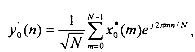
controllable selector 206. - An output from reverse sign (-)
complex conjugate unit 205 is - X * 1 = [-x * 1(0),-x * 1(1),···,-x * 1(N - 1)]. Then, signal - X * 1 to be transmitted is supplied to inverse fast Fourier transform (IFFT)unit 208.IFFT unit 208 generates an inverse fast Fourier transform of -X * 1, in well know fashion, namely, Y ' 1 = [y ' 1 (0), y ' 1 (1),···, y ' 1(N -1)] = F -1 (X * 1), where, for n = 0,···, N - 1. In turn, Y ' 1 is supplied to a second input of
controllable selector 205. - It is noted that signals X 0, X 1, X * 0, and - X * 1 are frequency domain signals, and that Y 0, Y 1, Y ' 0, and Y ' 1 are time domain signals.
-
Controllable selector 205, under control ofselect input 217, supplies Y 0 during a first, e.g., an even, OFDM interval and Y ' 1 during a second, e.g., an odd, OFDM interval, as an output which is supplied tocyclic prefix unit 209. In turn,cyclic prefix unit 209 prepends a cyclic prefix to each OFDM interval, i.e., each symbol period. The cyclic prefix is used to compensate for the dispersion introduced by the channel response and by a pulse shaping filter (not shown) used in the transmitter. Note that the cyclic prefix is added only for those tones used in an OFDM transmitter. Since the instant transmitter is primarily intended for use in a base station, a cyclic prefix is added for all of the available orthogonal tones. However, if the transmitter were to be used in a mobile unit using only a single OFDM tone, then the cyclic prefix uses only the particular single tone being used by the mobile unit. Then, the prepended Y 0 or Y ' 1 signal is converted to analog form via digital-to-analog (D/A)converter 210 and supplied toRF transmitter 211 for transmission viaantenna 212, i.e.,antenna 0. Note thatRF transmitter 211 performs a conventional baseband-to-passband conversion of the OFDM signal for transmission. - Similarly,
controllable selector 206, under control ofselect input 218, supplies Y 1 during a first, e.g., an even, OFDM interval and Y ' 0 during a second, e.g., an odd, OFDM interval, as an output tocyclic prefix unit 213. In turn,cyclic prefix unit 213 prepends a cyclic prefix to each OFDM interval, i.e., each symbol period. The cyclic prefix is used to compensate for the dispersion introduced by the channel response and by a pulse shaping filter (not shown) used in the transmitter. Note that the cyclic prefix is added only for those tones used in an OFDM transmitter. Since the instant transmitter is primarily intended for use in a base station, a cyclic prefix is added for all of the available orthogonal tones. However, if the transmitter were to be used in a mobile unit using only a single OFDM tone, then the cyclic prefix uses only the particular single tone being used by the mobile unit. Then, the prepended Y 1 or Y ' 0 signal is converted to analog form via digital-to-analog (D/A)converter 214 and supplied toRF transmitter 215 for transmission viaantenna 216, i.e.,antenna 1. - FIG. 3 shows, in simplified block diagram form, details of a reduced complexity implement of an OFDM transmit diversity system in accordance with the invention. Specifically, N length signal vector X 0 = [x 0(0),x 0(1),···,x 0(N - 1)] to be transmitted is supplied to inverse fast Fourier transform (IFFT)
unit 301 which obtains the inverse fast Fourier transform of signal X 0, in well known fashion, and yields Y 0. In this example, Y 0 = [y 0(0), y 0(1),···,(N - 1)] = F -1(X 0), which is the N-point IFFT of X 0 and where, for n = 0, ···, N - 1. In turn, Y 0 is supplied to a first input of
controllable selector 302 and to reverse ordercomplex conjugate unit 303. Note that signal vector X 0 is a digital signal that has already been encoded and modulated, e.g., using PSK, QAM or the like. - Similarly, N length signal vector X 1 = [x 1(0),x 1(1),···,x 1(N - 1)] to be transmitted is supplied to inverse fast Fourier transform (IFFT)
unit 304 which obtains the inverse fast Fourier transform of signal X 1, in well known fashion, and yields Y 1. In this example, Y 1 = [y 1(0),y 1(1),···,y 1(N - 1)] = F -1(X 1), which is the N-point IFFT of X 1 and wherefor n = 0,···,N - 1. In turn, Y 1 is supplied to a first input of
controllable selector 305 and to reverse order, reverse sign (-)complex conjugate unit 306. Note that signal vector X 1 is also a digital signal that has already been encoded and modulated, e.g., using PSK, QAM or the like. - Reverse order
complex conjugate unit 303 generates the inverse Fourier transform of X * 0 from Y 0, namely, Y ' 0 =[y ' 0(0),y ' 0(1),···,y ' 0(N - 1)] = F -1(X * 0). whereand where* denotes the complex conjugate. Note with reverse order, y ' 0(0) = y * 0(N) = y * 0(0), y ' 0(1) = y * 0(N - 1),···,y ' 0(N - 1) = y * 0(1). In turn, Y ' 0 is supplied to a second input of
controllable selector 305. Note thatcontrollable selector 305 is controlled via a signal supplied to controlinput 314 to select as an output, either a signal supplied to its first input or a signal supplied to its second input, namely, either Y 1 or Y ' 0, respectively. - Similarly, reverse order, reverse sign (-)
complex conjugate unit 306 generates the inverse sign (-), reverse order Fourier transform of X * 1 of Y 1, namely, Y ' 1 = [y ' 1(0),y ' 1(1),···,y ' 1(N - 1)] = F -1(X * 1), whereand where * denotes the complex conjugate. Note with reverse order, y ' 1 (0) = -y * 1(N) = -y * 1(0), y ' 1(1) = -y* 1 (N-1), ···, y ' 1 (N - 1) = -y * 1(1). In turn, Y ' 1 is supplied to a second input of
controllable selector 302. Note thatcontrollable selector 302 is also controlled via a signal supplied to controlinput 313 to select as an output, either a signal supplied to its first input or a signal supplied to its second input, namely, either Y 0 or Y ' 1, respectively. - An output from
controllable selector 302 is supplied tocyclic prefix unit 307, which prepends a cyclic prefix to each OFDM interval, i.e., each symbol period. The cyclic prefix is used to compensate for the dispersion introduced by the channel response and by a pulse shaping filter (not shown) used in the transmitter. Note that the cyclic prefix is added only for those tones used in an OFDM transmitter. Since the instant transmitter is primarily intended for use in a base station, a cyclic prefix is added for all of the available orthogonal tones. However, if the transmitter were to be used in a mobile unit using only a single OFDM tone, then the cyclic prefix uses only the particular single tone being used by the mobile unit. Then, the prepended Y 0 or Y ' 1 signal is converted to analog form via digital-to-analog (D/A)converter 308 and supplied toRF transmitter 309 for transmission viaantenna 310, i.e.,antenna 0. - Similarly, an output from
controllable selector 305 is supplied tocyclic prefix unit 311, which prepends a cyclic prefix to each OFDM interval, i.e., each symbol period. Again, the cyclic prefix is used to compensate for the dispersion introduced by the channel response and by a pulse shaping filter (not shown) used in the transmitter. Note that the cyclic prefix is added only for those tones used in an OFDM transmitter. Since the instant transmitter is primarily intended for use in a base station, a cyclic prefix is added for all of the available orthogonal tones. However, if the transmitter were to be used in a mobile unit using only a single OFDM tone, then the cyclic prefix uses only the particular single tone being used by the mobile unit. Then, the prepended Y 1 or Y ' 0 signal is converted to analog form via digital-to-analog (D/A)converter 312 and supplied toRF transmitter 313 for transmission viaantenna 314, i.e.,antenna 1. - Thus, in first, e.g., even, OFDM intervals
controllable selectors - Therefore, it is seen that the transmit diversity is realized in OFDM by employing a significantly less complex implement than that shown in FIG. 2.
- In another embodiment of the invention, more than two transmit antennas are advantageously employed to realize the transmit diversity. In each frequency subchannel two of the antennas are grouped together and use the signal pattern shown in FIGs. 1A and 1B. It is noted that the grouping pattern, i.e., the selection of antennas for each frequency subchannel may vary.
- Further note that although the following example employs four antennas any number greater than two may be employed. Additionally, hereinafter "frequency subchannel" is referred to as just "subchannel".
- FIG. 4A graphically illustrates the pairing of signals in time for use in an embodiment of the invention in transmitting from a first antenna, in this example,
antenna 0, in an antenna-group hopping OFDM transmit diversity system. Thus, as shown, in a first OFDM time interval: a first subchannel includes signal component x 0(0); a second subchannel includes a zero (0); a third subchannel includes signal component x 0(2); a fourth subchannel includes a zero (0); etc., and in a second OFDM time interval: the first subchannel includes signal component - x * 1(0); the second subchannel includes a zero (0); the third subchannel includes signal component - x * 1 (2) ; a fourth subchannel includes a zero (0); etc. - FIG. 4B graphically illustrates the pairing of signals in time for use in an embodiment of the invention in transmitting from a second antenna in an antenna-group hopping OFDM transmit diversity system. Thus, as shown, in a first OFDM time interval: a first subchannel includes signal component x 1(0); a second subchannel includes a zero (0); a third subchannel includes a zero (0); a fourth subchannel includes signal component x 0(3); etc., and in a second OFDM time interval: the first subchannel includes signal component x * 0(0); the second subchannel includes a zero (0); the third subchannel includes a zero (0); a fourth subchannel includes signal component - x * 1(3); etc.
- FIG. 4C graphically illustrates the pairing of signals in time for use in an embodiment of the invention in transmitting from a third antenna in an antenna-group hopping OFDM transmit diversity system. Thus, as shown, in a first OFDM time interval: a first subchannel includes a zero (0); a second subchannel includes signal component x 0(1); a third subchannel includes signal component x 1(2); a fourth subchannel includes a zero (0); etc., and in a second OFDM time interval: the first subchannel includes a zero (0); the second subchannel includes signal component - x * 1(1); the third subchannel includes signal component x * 0(2); a fourth subchannel includes a zero (0); etc.
- FIG. 4D graphically illustrates the pairing of signals in time for use in an embodiment of the invention in transmitting from a fourth antenna in an antenna-group hopping OFDM transmit diversity system. Thus, as shown, in a first OFDM time interval: a first subchannel includes a zero (0); a second subchannel includes signal component x 1 (1); a third subchannel includes a zero (0); a fourth subchannel includes signal component x 1(3); etc., and in a second OFDM time interval: the first subchannel includes a zero (0); the second subchannel includes signal component x * 0(1); the third subchannel includes a zero (0); a fourth subchannel includes signal component x * 0(3) ; etc.
- As shown, in each group of two (2) antennas, the signal components are paired in time on each subchannel. In this example, the grouping of the antennas varies from subchannel to subchannel. On a
first subchannel antennas antennas third subchannel antennas fourth subchannel antennas - FIG. 5 shows, in simplified block diagram form, details of an embodiment of the invention for use in effecting antenna-group hopping in an OFDM transmit diversity system. Specifically, N length signal vector X 0 = [x 0(0), x 0(1), ···, x 0(N - 1)] to be transmitted is supplied to "signal and select processor, and distributor" 501. Similarly, N length signal vector X 1 = [x 1 (0), x 1 (1),···, x 1(N - 1)] also to be transmitted is also supplied to signal and select processor, and
distributor 501. As shown above in relationship to the embodiment of the invention of FIG. 2, signal and select processor, anddistributor 501 is operative to generate the complex conjugate of signal vector X 0, namely, X * 0 = [x * 0 (0), x * 0((1); ···, x * 0] (N - 1)], and the reverse sign (-) complex conjugate of signal vector X 1, namely, - X * 1 = [-x * 1 (0),-x * 1; (1), ···,-x* 1 (N - 1)] From the signal components of X 0, X 1, X * 0 and - X * 1 signal and select processor, anddistributor 501 generates, in this example, the matrix of signal as shown in FIG. 6. Specifically, signals are generated as represented by X ' 0, X ' 1, X ' 2, X ' 3, X' 4, X ' 5, X ' 6 and X ' 7. As shown in FIG. 6: - Then, X ' 0 is supplied to
IFFT unit 502 that generates the inverse fast Fourier transform thereof, namely, Z'0 = F -1 X' 0, in a manner similar to that described above in relationship to the embodiment of the invention of FIG. 2. Z ' 0 is supplied to a first input ofcontrollable selector 503. - Similarly, X ' 1 is supplied to
IFFT unit 504 that generates the inverse fast Fourier transform thereof, namely, Z ' 1 = F -1 X ' 1, also in a manner similar to that described above in relationship to the embodiment of the invention of FIG. 2. Z' 1 is supplied to a second input ofcontrollable selector 503.Controllable selector 503 is responsive to control signals supplied toterminal 515, from select bus 514 generated by signal and select processor, anddistributor 501, to realize selection of the signal components during alternate OFDM time intervals, e.g., during even and odd intervals. - The output from
controllable selector 503 is supplied tocyclic prefix unit 516 that prepends a cyclic prefix to each OFDM interval, i.e., each symbol period, as described above. Then, the prepended Z ' 0 or Z ' 1 signal is converted to analog form via digital-to-analog (D/A)converter 517 and supplied toRF transmitter 518 for transmission viaantenna 519, i.e.,antenna 0. - X ' 2 is supplied to
IFFT unit 505 that generates the inverse fast Fourier transform thereof, namely, Z ' 2 = F -1 X ' 2, in a manner similar to that described above in relationship to the embodiment of the invention of FIG. 2. Z' 2 is supplied to a first input ofcontrollable selector 506. - Similarly, X ' 3 is supplied to
IFFT unit 507 that generates the inverse fast Fourier transform thereof, namely, Z ' 3 = F -1 X ' 3, also in a manner similar to that described above in relationship to the embodiment of the invention of FIG. 2. Z ' 3 is supplied to a second input ofcontrollable selector 506.Controllable selector 506 is responsive to control signals supplied toterminal 520, from select bus 514 generated by signal and select processor, anddistributor 501, to realize selection of the signal components during alternate OFDM time intervals, e.g., during even and odd intervals. - The output from
controllable selector 506 is supplied tocyclic prefix unit 521 that prepends a cyclic prefix to each OFDM interval, i.e., each symbol period, as described above. Then, the prepended Z ' 2 or Z ' 3 signal is converted to analog form via digital-to-analog (D/A)converter 522 and supplied toRF transmitter 523 for transmission viaantenna 524, i.e.,antenna 1. - X ' 4 is supplied to
IFFT unit 508 that generates the inverse fast Fourier transform thereof, namely, Z ' 4 = F -1 X ' 4, in a manner similar to that described above in relationship to the embodiment of the invention of FIG. 2. Z ' 4 is supplied to a first input ofcontrollable selector 509. - Similarly, X ' 5 is supplied to
IFFT unit 510 that generates the inverse fast Fourier transform thereof, namely, Z ' 5 = F -1 X ' 5, also in a manner similar to that described above in relationship to the embodiment of the invention of FIG. 2. Z ' 5 is supplied to a second input ofcontrollable selector 509.Controllable selector 509 is responsive to control signals supplied toterminal 525, from select bus 514 generated by signal and select processor, anddistributor 501, to realize selection of the signal components during alternate OFDM time intervals, e.g., during even and odd intervals. - The output from
controllable selector 509 is supplied tocyclic prefix unit 526 that prepends a cyclic prefix to each OFDM interval, i.e., each symbol period, as described above. Then, the prepended Z ' 4 or Z ' 5 signal is converted to analog form via digital-to-analog (D/A)converter 527 and supplied toRF transmitter 528 for transmission viaantenna 529, i.e.,antenna 2. - X ' 6 is supplied to
IFFT unit 511 that generates the inverse fast Fourier transform thereof, namely, Z ' 6 = F -1 X ' 6, in a manner similar to that described above in relationship to the embodiment of the invention of FIG. 2. Z ' 6 is supplied to a first input ofcontrollable selector 512. - Similarly, X ' 7 is supplied to
IFFT unit 513 that generates the inverse fast Fourier transform thereof, namely, Z ' 7 = F -1 X ' 7, also in a manner similar to that described above in relationship to the embodiment of the invention of FIG. 2. Z ' 7 is supplied to a second input ofcontrollable selector 512.Controllable selector 512 is responsive to control signals supplied toterminal 530, from select bus 514 generated by signal and select processor, anddistributor 501, to realize selection of the signal components during alternate OFDM time intervals, e.g., during even and odd intervals. - The output from
controllable selector 512 is supplied tocyclic prefix unit 531 that prepends a cyclic prefix to each OFDM interval, i.e., each symbol period, as described above. Then, the prepended Z ' 6 or Z ' 7 signal is converted to analog form via digital-to-analog (D/A)converter 532 and supplied toRF transmitter 533 for transmission viaantenna 534, i.e.,antenna 3. - It is further noted that the antenna grouping can be in clusters of tones, instead of tone-by-tone. Indeed, other special antenna grouping patterns are also readily realizable without departing from the spirit and scope of the invention. For one clustered OFDM communication system, see United States patent 5,914,933, issued June 22, 1999.
- The above-described embodiments are, of course, merely illustrative of the principles of the invention. Indeed, numerous other methods or apparatus may be devised by those skilled in the art without departing from the spirit and scope of the invention. Specifically, it is noted that although the invention was described in terms of pairing signal in time, they could equally be paired in frequency or paired both in time and frequency. Additionally, over sampled signals may be utilized.
Claims (24)
- Apparatus for use in a wireless communication system to realize transmit diversity including first and second frequency domain signals to be transmitted,
the apparatus being CHARACTERIZED BY:means adapted to generate a third frequency domain signal representative of a complex conjugate of said first frequency domain signal;means adapted to generate a fourth frequency domain signal representative of a reverse sign (-) complex conjugate of said second frequency domain signal;means adapted to generate first through fourth time domain signals representative of said first through fourth frequency domain signals, respectively; andmeans adapted to pair selected components of said first through fourth time domain signals in prescribed time intervals for transmission, whereby transmit diversity is provided for frequency-fading channels in the wireless communication system. - The apparatus as defined in claim 1 wherein said means adapted to generate said time domain signals includes means adapted to transform said frequency domain signals into said time domain signals by obtaining inverse fast Fourier transforms of said frequency domain signals.
- The apparatus as defined in claim 2 wherein said means adapted to transform includes a plurality of means adapted to obtain inverse fast Fourier transforms, wherein each of said plurality of means adapted to obtain inverse fast Fourier transforms are associated on a one-to-one basis with an individual one of said frequency domain signals.
- The apparatus as defined in claim 1 further including a first antenna means and at least a second antenna means adapted to transmit said time domain signals, and wherein said means adapted to pair includes at least a first controllable selector means adapted to controllably select signal components of said first time domain signal for transmission on said first antenna means during first time intervals and adapted to controllably select signal components of said fourth time domain signal for transmission on said first antenna means during second time intervals, and a second controllable selector means adapted to controllably select signal components of said second time domain signal for transmission on said second antenna means during first time intervals and adapted to controllably select signal components of said third time domain signal for transmission on said second antenna means during second time intervals.
- The apparatus as defined in claim 4 wherein said first and second time intervals are orthogonal frequency division multiplexing (OFDM) symbol intervals, and said means adapted to generate said time domain signals includes a plurality of means adapted to obtain inverse fast Fourier transforms, wherein each of said plurality of means adapted to obtain inverse fast Fourier transforms is associated on a one-to-one basis with an individual one of said frequency domain signals to transform said frequency domain signals into said time domain signals.
- The apparatus as defined in claim 5 wherein said first frequency domain signal is of the form X0 = [x 0 (0), x 0 (1), ···, x 0 (N - 1)] and its corresponding first time domain signal is of the form Y 0 = [y 0(0),y 0(1), ···,(N -1)] = F -1(X 0), where F -1 is the inverse Fourier transform andfor n = 0,···,N - 1·

- The apparatus as defined in claim 5 wherein said second frequency domain signal is of the form X 1 = [x 1(0),x 1(1),···,x 1(N - 1)] and its corresponding second time domain signal is of the form Y 1 = [y 1(0),y 1(1),···,y 1(N - 1)] = F -1(X 1), where F -1 is the inverse Fourier transform andfor n = 0,···, N - 1.

- The apparatus as defined in claim 5 wherein said third frequency domain signal is of the form X * 0 = [x * 0(0),x * 0(1),···, x * 0 (N - 1)] and its corresponding third time domain signal is of the form Y'0 =[y'0(0),y'0(1),···,y'0(N - 1)] F -1 (X* 0), where F -1 is the inverse Fourier transform and * denotes complex conjugate andfor n = 0,···, N - 1 and where * denotes the complex conjugate.

- The apparatus as defined in claim 5 wherein said fourth frequency domain signal is of the form - X * 1 = [-x * 1(0),-x * 1(1),···,-x * 1(N - 1)] and its corresponding fourth time domain signal is of the form Y'1 = [y'1(0), y'1(1),···y'1(N - 1)] = F -1(X * 1), where F -1 is the inverse Fourier transform and * denotes complex conjugate andfor n = 0,···, N - 1 and where * denotes the complex conjugate.

- Apparatus for use in a wireless communication system to realize transmit diversity including first and second frequency domain signals to be transmitted,
the apparatus being CHARACTERIZED BY:means adapted to generate first and second time domain signals representative of said first and second frequency domain signals, respectively;means adapted to generate a third time domain signal representative of a reverse order complex conjugate of said first time domain signal;means adapted to generate a fourth time domain signal representative of a reverse order, reverse sign (-) complex conjugate of said second time domain signal; andmeans adapted to pair selected components of said first through fourth time domain signals in prescribed time intervals for transmission, whereby transmit diversity is provided for frequency-fading channels in the wireless communication system. - The apparatus as defined in claim 10 wherein said means adapted to generate first and second time domain signals includes means adapted to transform said frequency domain signals into said time domain signals by obtaining inverse fast Fourier transforms of said frequency domain signals.
- The apparatus as defined in claim 11 wherein said means adapted to transform includes a plurality of means adapted to obtain inverse fast Fourier transforms, wherein each of said plurality of means adapted to obtain inverse fast Fourier transforms is associated on a one-to-one basis with an individual one of said frequency domain signals.
- The apparatus as defined in claim 10 further including a first antenna means and at least a second antenna means adapted to transmit said time domain signals, and wherein said means adapted to pair includes at least a first controllable selector means adapted to controllably select signal components of said first time domain signal for transmission on said first antenna means during first time intervals and adapted to controllably select signal components of said fourth time domain signal for transmission on said first antenna means during second time intervals, and a second controllable selector means adapted to controllably select signal components of said second time domain signal for transmission on said second antenna means during first time intervals and adapted to controllably select signal components of said third time domain signal for transmission on said second antenna means during second time intervals.
- The apparatus as defined in claim 13 wherein said first and second time intervals are orthogonal frequency division multiplexing (OFDM) symbol intervals, and said means adapted to generate said time domain signals includes a plurality of means adapted to obtain inverse fast Fourier transforms, wherein individual ones of said plurality of means adapted to obtain inverse fast Fourier transforms is associated on a one-to-one basis with an individual one of said frequency domain signals to transform said frequency domain signals into said time domain signals.
- The apparatus as defined in claim 14 wherein said first frequency domain signal is of the form X 0 = [x 0(0), x 0(1),···,x 0(N - 1)] and its corresponding first time domain signal is of the form Y 0 = [y 0(0), y 0(1), ···, (N - 1)] = F -1(X 0), where F -1 is the inverse Fourier transform andfor n = 0,···, N - 1.

- The apparatus as defined in claim 14 wherein said second frequency domain signal is of the form X 1 =[x 1(0),x 1(1),···,x 1(N - 1)] and its corresponding second time domain signal is of the form Y 1 = [y 1(0),y 1(1),···,y 1(N - 1)] = F -1(X 1), where F -1 is the inverse Fourier transform andfor n = 0,···, N - 1.

- The apparatus as defined in claim 14 wherein said third time domain signal is of the form Y'0 = [y'0(0), y'0(1),···,y'0(N - 1)] and y'0(n) = y * 0(N - n), for n = 0,···, N - 1, where with reverse order, y'0(0) = y * 0(N) = y * 0(0), y'0(1) = y * 0(N - 1),···,y'0(N - 1) = y * 0(1), and where * denotes the complex conjugate.
- The apparatus as defined in claim 14 wherein said fourth time domain signal is of the form Y'1 = [y'1(0),y'1(1),···,y'1(N - 1)] and y'1(n) = -y * 1(N - n), for n = 0,···, N - 1, where with reverse order, y'1(0) = -y * 1(N) = -y * 1(0), y'1(1) = -y * 1(N - 1),···,y'1(N - 1) = -y * 1(1), and where * denotes the complex conjugate.
- Apparatus for use in a wireless communication system to realize transmit diversity through antenna hopping including first and second frequency domain signals to be transmitted,
the apparatus being CHARACTERIZED BY:means adapted to generate a third frequency domain signal representative of a complex conjugate of said first frequency domain signal;means adapted to generate a fourth frequency domain signal representative of a reverse sign (-) complex conjugate of said second frequency domain signal;first means adapted to select prescribed frequency components of said first through fourth frequency domain signals for inclusion into a plurality of frequency domain signals having a selected prescribed relationship to a plurality of antennas including at least three antennas, said selected prescribed relationship being such that two antennas are assigned to each of a plurality of frequency subchannels for transmission of signals;means adapted to convert said plurality of frequency domain signals into a corresponding plurality of time domain signals; andsecond means adapted to select prescribed ones of said plurality of time domain signals in prescribed time intervals for transmission, whereby transmit diversity is provided for frequency-fading channels in the wireless communication system. - The apparatus as defined in claim 19 wherein said means adapted to convert includes means adapted to transform said frequency domain signals into said time domain signals by obtaining inverse Fourier transforms.
- The apparatus as defined in claim 20 wherein said means adapted to transform includes a plurality of means adapted to obtain inverse fast Fourier transforms, wherein each of said plurality of means adapted to obtain inverse fast Fourier transforms is associated on a one-to-one basis with an individual one of said frequency domain signals.
- The apparatus as defined in claim 21 wherein said time intervals are orthogonal frequency division multiplexing (OFDM) symbol intervals.
- The apparatus as defined in claim 22 wherein said first means adapted to select selects said frequency components such that a different set including two antennas of said at least three antennas is assigned to frequency subchannels in a prescribed sequence of said antenna groups.
- The apparatus as defined in claim 23 further including a fourth antenna to transmit said time domain signals, and wherein said first means adapted to select selects said frequency components such that a different set including two antennas of said at least four antennas is assigned to frequency subchannels in a prescribed sequence of said antenna groups.
Applications Claiming Priority (2)
| Application Number | Priority Date | Filing Date | Title |
|---|---|---|---|
| US568170 | 1984-01-04 | ||
| US09/568,170 US7020072B1 (en) | 2000-05-09 | 2000-05-09 | Orthogonal frequency division multiplexing transmit diversity system for frequency-selective fading channels |
Publications (3)
| Publication Number | Publication Date |
|---|---|
| EP1156598A2 true EP1156598A2 (en) | 2001-11-21 |
| EP1156598A3 EP1156598A3 (en) | 2005-11-30 |
| EP1156598B1 EP1156598B1 (en) | 2009-04-29 |
Family
ID=24270190
Family Applications (1)
| Application Number | Title | Priority Date | Filing Date |
|---|---|---|---|
| EP01303929A Expired - Lifetime EP1156598B1 (en) | 2000-05-09 | 2001-04-30 | Orthogonal frequency division multiplexing transmit diversity system for frequency-selective fading channels |
Country Status (9)
| Country | Link |
|---|---|
| US (1) | US7020072B1 (en) |
| EP (1) | EP1156598B1 (en) |
| JP (1) | JP3768831B2 (en) |
| KR (1) | KR100719785B1 (en) |
| CN (1) | CN1323109A (en) |
| AU (1) | AU4028701A (en) |
| BR (1) | BR0101646A (en) |
| CA (1) | CA2341808A1 (en) |
| DE (1) | DE60138506D1 (en) |
Cited By (13)
| Publication number | Priority date | Publication date | Assignee | Title |
|---|---|---|---|---|
| WO2006048717A2 (en) | 2004-11-03 | 2006-05-11 | Nokia Corporation | System and method for space-time frequency coding in a multi-antenna transmission system |
| EP1884048A2 (en) * | 2005-05-03 | 2008-02-06 | Motorola, Inc. | Transmission of signalling information in an ofdm communication system |
| US7433413B2 (en) | 2003-12-24 | 2008-10-07 | Samsung Electronics Co., Ltd | Data transmission apparatus and method in an OFDM communication system |
| US7634016B2 (en) | 2006-04-25 | 2009-12-15 | Microsoft Corporation | Variable OFDM subchannel coding and modulation |
| US7929623B2 (en) | 2007-03-30 | 2011-04-19 | Microsoft Corporation | FEC in cognitive multi-user OFDMA |
| US7933344B2 (en) | 2006-04-25 | 2011-04-26 | Mircosoft Corporation | OFDMA based on cognitive radio |
| US7970085B2 (en) | 2007-05-08 | 2011-06-28 | Microsoft Corporation | OFDM transmission and reception for non-OFDMA signals |
| US8144793B2 (en) | 2006-12-12 | 2012-03-27 | Microsoft Corporation | Cognitive multi-user OFDMA |
| US8189621B2 (en) | 2006-05-12 | 2012-05-29 | Microsoft Corporation | Stack signaling to application with lack of requested bandwidth |
| US8374130B2 (en) | 2008-01-25 | 2013-02-12 | Microsoft Corporation | Orthogonal frequency division multiple access with carrier sense |
| US8855087B2 (en) | 2008-12-18 | 2014-10-07 | Microsoft Corporation | Wireless access point supporting control by multiple applications |
| US10700800B2 (en) | 2003-05-21 | 2020-06-30 | Regents Of The University Of Minnesota | Estimating frequency-offsets and multi-antenna channels in MIMO OFDM systems |
| CN113489503A (en) * | 2021-07-01 | 2021-10-08 | 维沃移动通信有限公司 | Radio frequency architecture and electronic device |
Families Citing this family (44)
| Publication number | Priority date | Publication date | Assignee | Title |
|---|---|---|---|---|
| US7952511B1 (en) | 1999-04-07 | 2011-05-31 | Geer James L | Method and apparatus for the detection of objects using electromagnetic wave attenuation patterns |
| US8363744B2 (en) * | 2001-06-10 | 2013-01-29 | Aloft Media, Llc | Method and system for robust, secure, and high-efficiency voice and packet transmission over ad-hoc, mesh, and MIMO communication networks |
| EP2755344B1 (en) | 2000-08-24 | 2018-07-25 | Sony Deutschland Gmbh | Communication device for transmitting OFDM signals in a wireless communication system |
| US8339935B2 (en) * | 2000-09-01 | 2012-12-25 | Apple Inc. | Adaptive time diversity and spatial diversity for OFDM |
| US6985434B2 (en) * | 2000-09-01 | 2006-01-10 | Nortel Networks Limited | Adaptive time diversity and spatial diversity for OFDM |
| CN100407612C (en) * | 2000-11-22 | 2008-07-30 | 北方电讯网络有限公司 | Method and device for turbo space-time trellis coding |
| MXPA03005307A (en) * | 2000-12-15 | 2004-12-02 | Adaptix Inc | Multi-carrier communications with group-based subcarrier allocation. |
| US6947748B2 (en) | 2000-12-15 | 2005-09-20 | Adaptix, Inc. | OFDMA with adaptive subcarrier-cluster configuration and selective loading |
| US7061854B2 (en) * | 2001-10-15 | 2006-06-13 | Nortel Networks Limited | Efficient OFDM communications with interference immunity |
| CN1290281C (en) | 2001-11-10 | 2006-12-13 | 三星电子株式会社 | Apparatus and method for coding/decoding of STTD in OFDM mobile communication system |
| JP3997890B2 (en) | 2001-11-13 | 2007-10-24 | 松下電器産業株式会社 | Transmission method and transmission apparatus |
| JP3963737B2 (en) | 2002-02-28 | 2007-08-22 | 松下電器産業株式会社 | Multi-carrier signal generation method, radio transmission apparatus, and radio reception apparatus |
| US7577085B1 (en) | 2002-06-03 | 2009-08-18 | Marvell International Ltd. | Multicarrier transmit diversity |
| WO2004004178A1 (en) * | 2002-06-28 | 2004-01-08 | Micronas Gmbh | Wireless audio signal transmission method for a three-dimensional sound system |
| US7394754B2 (en) * | 2002-08-01 | 2008-07-01 | Mediatek Inc. | System and method for transmitting data in a multiple-branch transmitter-diversity orthogonal frequency-division multiplexing (OFDM) system |
| KR100511559B1 (en) | 2002-11-28 | 2005-08-31 | 한국전자통신연구원 | Transmitting and Receiving Method having Distortion Reduction Caused by a Time-varying Channel in an Orthogonal Frequency Division Multiplex System |
| KR100950646B1 (en) * | 2003-10-16 | 2010-04-01 | 삼성전자주식회사 | Method for transmitting preamble in order to synchronous mimo ofdm communication system |
| WO2005081439A1 (en) | 2004-02-13 | 2005-09-01 | Neocific, Inc. | Methods and apparatus for multi-carrier communication systems with adaptive transmission and feedback |
| CN1832466B (en) * | 2004-03-12 | 2011-05-04 | 株式会社东芝 | Ofdm signal transmission method and apparatus |
| US7447268B2 (en) * | 2004-03-31 | 2008-11-04 | Intel Corporation | OFDM system with per subcarrier phase rotation |
| CN1965513B (en) | 2004-05-01 | 2014-11-26 | 桥扬科技有限公司 | Methods and apparatus for communication with time-division duplexing |
| US8285226B2 (en) * | 2004-05-07 | 2012-10-09 | Qualcomm Incorporated | Steering diversity for an OFDM-based multi-antenna communication system |
| US7724835B2 (en) * | 2004-05-17 | 2010-05-25 | Qualcomm Incorporated | Space-time block coding in orthogonal frequency division communication systems |
| US7616557B2 (en) * | 2004-05-17 | 2009-11-10 | California Institute Of Technology | Method and apparatus for canceling intercarrier interference through conjugate transmission for multicarrier communication systems |
| CN102655446B (en) | 2004-06-30 | 2016-12-14 | 亚马逊科技公司 | Apparatus and method and communication means for control signal transmission |
| US7263335B2 (en) * | 2004-07-19 | 2007-08-28 | Purewave Networks, Inc. | Multi-connection, non-simultaneous frequency diversity in radio communication systems |
| WO2006014143A1 (en) * | 2004-08-03 | 2006-02-09 | Agency For Science, Technology And Research | Method for transmitting a digital data stream, transmitter, method for receiving a digital data stream and receiver |
| US8484272B2 (en) | 2004-08-20 | 2013-07-09 | Qualcomm Incorporated | Unified pulse shaping for multi-carrier and single-carrier waveforms |
| US8130855B2 (en) | 2004-11-12 | 2012-03-06 | Interdigital Technology Corporation | Method and apparatus for combining space-frequency block coding, spatial multiplexing and beamforming in a MIMO-OFDM system |
| KR100689484B1 (en) * | 2004-11-29 | 2007-03-02 | 삼성전자주식회사 | Diversity method and apparatus in mobile communication system |
| US7573851B2 (en) * | 2004-12-07 | 2009-08-11 | Adaptix, Inc. | Method and system for switching antenna and channel assignments in broadband wireless networks |
| US7773703B2 (en) * | 2005-07-08 | 2010-08-10 | Qualcomm Incorporated | Methods and apparatus for communicating using a DC tone |
| US7773679B2 (en) * | 2005-07-08 | 2010-08-10 | Qualcomm Incorporated | Base station methods and apparatus for DC tone special treatment |
| KR100768511B1 (en) | 2005-07-19 | 2007-10-18 | 한국전자통신연구원 | Base station transmitter of system for mc-cdma, transmit diversity method for that system, base station transmitter of system for scattered mc-cdma, transmit diversity method for thar system |
| EP1929693A2 (en) * | 2005-09-23 | 2008-06-11 | Koninklijke Philips Electronics N.V. | Space-time coded mb-ofdm uwb system |
| US8693430B2 (en) | 2005-09-28 | 2014-04-08 | Neocific, Inc. | Method and system for multi-carrier packet communication with reduced overhead |
| CN102684861B (en) * | 2005-09-28 | 2015-03-04 | 桥扬科技有限公司 | Orthogonal frequency division multiple access wireless packet system and base station thereof, mobile equipment and communication method. |
| JP4331221B2 (en) * | 2007-03-15 | 2009-09-16 | 株式会社東芝 | Wireless communication method, wireless transmission device, and wireless reception device |
| EP2071758A1 (en) * | 2007-12-11 | 2009-06-17 | Sony Corporation | OFDM-Transmitting apparatus and method, and OFDM-receiving apparatus and method |
| TW201034418A (en) * | 2008-08-18 | 2010-09-16 | Agency Science Tech & Res | Cyclic prefix schemes |
| US8724488B2 (en) | 2009-03-17 | 2014-05-13 | Interdigital Patent Holdings, Inc. | Method and apparatus for power control of sounding reference signal (SRS) transmission |
| EP2230788A1 (en) * | 2009-03-20 | 2010-09-22 | Mitsubishi Electric R&D Centre Europe B.V. | Method and device for determining a shifting parameter to be used by a telecommunication device for transferring symbols |
| MX356392B (en) * | 2014-08-07 | 2018-05-28 | One Media Llc | Dynamic configuration of a flexible orthogonal frequency division multiplexing phy transport data frame. |
| CA2955611C (en) | 2014-08-07 | 2022-03-22 | Coherent Logix, Incorporated | Multi-partition radio frames |
Citations (1)
| Publication number | Priority date | Publication date | Assignee | Title |
|---|---|---|---|---|
| WO1998009381A1 (en) * | 1996-08-29 | 1998-03-05 | The Board Of Trustees Of The Leland Stanford Junior University | High capacity wireless communication using spatial subchannels |
Family Cites Families (7)
| Publication number | Priority date | Publication date | Assignee | Title |
|---|---|---|---|---|
| US5914933A (en) | 1996-03-08 | 1999-06-22 | Lucent Technologies Inc. | Clustered OFDM communication system |
| US6185258B1 (en) | 1997-09-16 | 2001-02-06 | At&T Wireless Services Inc. | Transmitter diversity technique for wireless communications |
| JP3724940B2 (en) * | 1998-01-08 | 2005-12-07 | 株式会社東芝 | OFDM diversity receiver |
| US6728302B1 (en) * | 1999-02-12 | 2004-04-27 | Texas Instruments Incorporated | STTD encoding for PCCPCH |
| US6317411B1 (en) * | 1999-02-22 | 2001-11-13 | Motorola, Inc. | Method and system for transmitting and receiving signals transmitted from an antenna array with transmit diversity techniques |
| US6775260B1 (en) * | 1999-02-25 | 2004-08-10 | Texas Instruments Incorporated | Space time transmit diversity for TDD/WCDMA systems |
| US6542556B1 (en) * | 2000-03-31 | 2003-04-01 | Nokia Mobile Phones Ltd. | Space-time code for multiple antenna transmission |
-
2000
- 2000-05-09 US US09/568,170 patent/US7020072B1/en not_active Expired - Lifetime
-
2001
- 2001-03-23 CA CA002341808A patent/CA2341808A1/en not_active Abandoned
- 2001-04-30 BR BR0101646-6A patent/BR0101646A/en not_active Application Discontinuation
- 2001-04-30 DE DE60138506T patent/DE60138506D1/en not_active Expired - Lifetime
- 2001-04-30 EP EP01303929A patent/EP1156598B1/en not_active Expired - Lifetime
- 2001-05-02 AU AU40287/01A patent/AU4028701A/en not_active Abandoned
- 2001-05-08 CN CN01117929A patent/CN1323109A/en active Pending
- 2001-05-09 KR KR1020010025188A patent/KR100719785B1/en active IP Right Grant
- 2001-05-09 JP JP2001138083A patent/JP3768831B2/en not_active Expired - Lifetime
Patent Citations (1)
| Publication number | Priority date | Publication date | Assignee | Title |
|---|---|---|---|---|
| WO1998009381A1 (en) * | 1996-08-29 | 1998-03-05 | The Board Of Trustees Of The Leland Stanford Junior University | High capacity wireless communication using spatial subchannels |
Non-Patent Citations (1)
| Title |
|---|
| LI Y ET AL: "TRANSMITTER DIVERSITY FOR OFDM SYSTEMS WITH MOBILE WIRELESS CHANNELS" IEEE GLOBECOM 1998. GLOBECOM '98. THE BRIDGE TO GLOBAL INTEGRATION. SYDNEY, NOV. 8 - 12, 1998, IEEE GLOBAL TELECOMMUNICATIONS CONFERENCE, NEW YORK, NY : IEEE, US, vol. VOL. 2, 1998, pages 968-973, XP000825893 ISBN: 0-7803-4985-7 * |
Cited By (32)
| Publication number | Priority date | Publication date | Assignee | Title |
|---|---|---|---|---|
| US11303377B2 (en) | 2003-05-21 | 2022-04-12 | Regents Of The University Of Minnesota | Estimating frequency-offsets and multi-antenna channels in MIMO OFDM systems |
| US10700800B2 (en) | 2003-05-21 | 2020-06-30 | Regents Of The University Of Minnesota | Estimating frequency-offsets and multi-antenna channels in MIMO OFDM systems |
| US7433413B2 (en) | 2003-12-24 | 2008-10-07 | Samsung Electronics Co., Ltd | Data transmission apparatus and method in an OFDM communication system |
| EP1810434A2 (en) * | 2004-11-03 | 2007-07-25 | Nokia Corporation | System and method for space-time frequency coding in a multi-antenna transmission system |
| EP1810434A4 (en) * | 2004-11-03 | 2011-03-23 | Nokia Corp | System and method for space-time frequency coding in a multi-antenna transmission system |
| WO2006048717A2 (en) | 2004-11-03 | 2006-05-11 | Nokia Corporation | System and method for space-time frequency coding in a multi-antenna transmission system |
| EP1884048A2 (en) * | 2005-05-03 | 2008-02-06 | Motorola, Inc. | Transmission of signalling information in an ofdm communication system |
| EP1884048A4 (en) * | 2005-05-03 | 2013-07-17 | Motorola Mobility Llc | Transmission of signalling information in an ofdm communication system |
| US7634016B2 (en) | 2006-04-25 | 2009-12-15 | Microsoft Corporation | Variable OFDM subchannel coding and modulation |
| US7933344B2 (en) | 2006-04-25 | 2011-04-26 | Mircosoft Corporation | OFDMA based on cognitive radio |
| US8189621B2 (en) | 2006-05-12 | 2012-05-29 | Microsoft Corporation | Stack signaling to application with lack of requested bandwidth |
| US8509265B2 (en) | 2006-05-12 | 2013-08-13 | Microsoft Corporation | Stack signaling to application with lack of requested bandwidth |
| US8923340B2 (en) | 2006-05-12 | 2014-12-30 | Microsoft Corporation | Signaling to application lack of requested bandwidth |
| US10182367B2 (en) | 2006-05-12 | 2019-01-15 | Microsoft Technology Licensing Llc | Signaling to application lack of requested bandwidth |
| US9386055B2 (en) | 2006-05-12 | 2016-07-05 | Microsoft Technology Licensing, Llc | Signaling to application lack of requested bandwidth |
| US9774415B2 (en) | 2006-12-12 | 2017-09-26 | Microsoft Technology Licensing, Llc | Cognitive multi-user OFDMA |
| US8144793B2 (en) | 2006-12-12 | 2012-03-27 | Microsoft Corporation | Cognitive multi-user OFDMA |
| US10581655B2 (en) | 2006-12-12 | 2020-03-03 | Microsoft Technology Licensing, Llc | Cognitive multi-user OFDMA |
| US9065687B2 (en) | 2006-12-12 | 2015-06-23 | Microsoft Technology Licensing, Llc | Cognitive multi-user OFDMA |
| US9866418B2 (en) | 2006-12-12 | 2018-01-09 | Microsoft Technology Licensing, Llc | Cognitive multi-user OFDMA |
| US9641273B2 (en) | 2006-12-12 | 2017-05-02 | Microsoft Technology Licensing, Llc | Cognitive multi-user OFDMA |
| US7929623B2 (en) | 2007-03-30 | 2011-04-19 | Microsoft Corporation | FEC in cognitive multi-user OFDMA |
| US8842752B2 (en) | 2007-03-30 | 2014-09-23 | Microsoft Corporation | FEC in cognitive multi-user OFDMA |
| US7970085B2 (en) | 2007-05-08 | 2011-06-28 | Microsoft Corporation | OFDM transmission and reception for non-OFDMA signals |
| US9755879B2 (en) | 2007-05-08 | 2017-09-05 | Microsoft Technology Licensing, Llc | OFDM transmission and reception for non-OFDM signals |
| US10177953B2 (en) | 2007-05-08 | 2019-01-08 | Microsoft Technology Licensing, Llc | OFDM transmission and reception for non-OFDM signals |
| US9363120B2 (en) | 2007-05-08 | 2016-06-07 | Microsoft Technology Licensing, Llc | OFDM transmission and reception for non-OFDM signals |
| US8718211B2 (en) | 2007-05-08 | 2014-05-06 | Microsoft Corporation | OFDM transmission and reception for non-OFDM signals |
| US9363795B2 (en) | 2008-01-25 | 2016-06-07 | Microsoft Technology Licensing, Llc | Orthogonal Frequency Division Multiple Access with carrier sense |
| US8374130B2 (en) | 2008-01-25 | 2013-02-12 | Microsoft Corporation | Orthogonal frequency division multiple access with carrier sense |
| US8855087B2 (en) | 2008-12-18 | 2014-10-07 | Microsoft Corporation | Wireless access point supporting control by multiple applications |
| CN113489503A (en) * | 2021-07-01 | 2021-10-08 | 维沃移动通信有限公司 | Radio frequency architecture and electronic device |
Also Published As
| Publication number | Publication date |
|---|---|
| EP1156598A3 (en) | 2005-11-30 |
| AU4028701A (en) | 2001-11-15 |
| US7020072B1 (en) | 2006-03-28 |
| CA2341808A1 (en) | 2001-11-09 |
| KR20010104656A (en) | 2001-11-26 |
| JP3768831B2 (en) | 2006-04-19 |
| BR0101646A (en) | 2001-12-26 |
| JP2002009735A (en) | 2002-01-11 |
| CN1323109A (en) | 2001-11-21 |
| KR100719785B1 (en) | 2007-05-21 |
| DE60138506D1 (en) | 2009-06-10 |
| EP1156598B1 (en) | 2009-04-29 |
Similar Documents
| Publication | Publication Date | Title |
|---|---|---|
| EP1156598B1 (en) | Orthogonal frequency division multiplexing transmit diversity system for frequency-selective fading channels | |
| US7436903B2 (en) | Multicarrier transmitter and method for transmitting multiple data streams with cyclic delay diversity | |
| US20070230431A1 (en) | Methods and Apparatus for Backwards Compatible Communication in a Multiple Antenna Communication System Using Fmd-Based Preamble Structures | |
| CN101248608B (en) | Mimo-ofdm transmission device and mimo-ofdm transmission method | |
| CN101569127B (en) | Base station device | |
| US20030072452A1 (en) | Preamble structures for single-input, single-output (SISO) and multi-input, multi-output (MIMO) communication systems | |
| CN101138163A (en) | Apparatus and method for mapping space-time coded data to subcarriers in a broadband wireless communication system | |
| US20010033623A1 (en) | Wireless communication | |
| WO2001071928A3 (en) | High efficiency, high performance communications system employing multi-carrier modulation | |
| CN101841384A (en) | Reception apparatus | |
| CN101171779A (en) | Method, apparatus, and system for transmitting and receiving information of an uncoded channel in an orthogonal frequency division multiplexing system | |
| KR100939738B1 (en) | Apparatus and method for cyclic delay diversity in multiple access broad band wireless communication system | |
| KR20050008388A (en) | Apparatus for generating preamble sequences in an orthogonal frequency division multiplexing communication system using a plurarity of transmission antennas and method thereof | |
| CN101208878B (en) | Transmit diversity scheme | |
| CN1894868B (en) | Method and transmitter for transmitting data in a multi-carrier system via a number of transmitting antennas | |
| WO2005004361A1 (en) | Multi-carrier radio transmission system, transmission device, and reception device | |
| JPH11205276A (en) | Multi-carrier modulator | |
| CN101282150B (en) | Transmission method capable of improving OFDMA system prefix sequence | |
| CN101001099A (en) | Distribution intermediate method and intermediate system | |
| EP1662684B1 (en) | Transmitter apparatus, receiver apparatus, transmitting method, receiving method, and program | |
| JP2002261727A (en) | Ofdm signal transmitter | |
| KR20050011292A (en) | Apparatus for generating preamble sequences in an orthogonal frequency division multiplexing communication system using a plurarity of transmission antennas and method thereof | |
| Ahmed et al. | Asymptotic performance of transmit diversity via OFDM for multipath channels | |
| CN1983894B (en) | Reception apparatus | |
| KR100807392B1 (en) | Digital transmission device for multi-antenna communication system |
Legal Events
| Date | Code | Title | Description |
|---|---|---|---|
| PUAI | Public reference made under article 153(3) epc to a published international application that has entered the european phase |
Free format text: ORIGINAL CODE: 0009012 |
|
| AK | Designated contracting states |
Kind code of ref document: A2 Designated state(s): AT BE CH CY DE DK ES FI FR GB GR IE IT LI LU MC NL PT SE TR |
|
| AX | Request for extension of the european patent |
Free format text: AL;LT;LV;MK;RO;SI |
|
| PUAL | Search report despatched |
Free format text: ORIGINAL CODE: 0009013 |
|
| AK | Designated contracting states |
Kind code of ref document: A3 Designated state(s): AT BE CH CY DE DK ES FI FR GB GR IE IT LI LU MC NL PT SE TR |
|
| AX | Request for extension of the european patent |
Extension state: AL LT LV MK RO SI |
|
| AKX | Designation fees paid |
Designated state(s): DE FI FR GB SE |
|
| 17P | Request for examination filed |
Effective date: 20060526 |
|
| GRAP | Despatch of communication of intention to grant a patent |
Free format text: ORIGINAL CODE: EPIDOSNIGR1 |
|
| GRAS | Grant fee paid |
Free format text: ORIGINAL CODE: EPIDOSNIGR3 |
|
| GRAA | (expected) grant |
Free format text: ORIGINAL CODE: 0009210 |
|
| AK | Designated contracting states |
Kind code of ref document: B1 Designated state(s): DE FI FR GB SE |
|
| REG | Reference to a national code |
Ref country code: GB Ref legal event code: FG4D |
|
| REF | Corresponds to: |
Ref document number: 60138506 Country of ref document: DE Date of ref document: 20090610 Kind code of ref document: P |
|
| PGFP | Annual fee paid to national office [announced via postgrant information from national office to epo] |
Ref country code: FI Payment date: 20090522 Year of fee payment: 9 |
|
| RAP4 | Party data changed (patent owner data changed or rights of a patent transferred) |
Owner name: LUCENT TECHNOLOGIES INC. |
|
| PG25 | Lapsed in a contracting state [announced via postgrant information from national office to epo] |
Ref country code: FI Free format text: LAPSE BECAUSE OF FAILURE TO SUBMIT A TRANSLATION OF THE DESCRIPTION OR TO PAY THE FEE WITHIN THE PRESCRIBED TIME-LIMIT Effective date: 20090429 |
|
| PG25 | Lapsed in a contracting state [announced via postgrant information from national office to epo] |
Ref country code: SE Free format text: LAPSE BECAUSE OF FAILURE TO SUBMIT A TRANSLATION OF THE DESCRIPTION OR TO PAY THE FEE WITHIN THE PRESCRIBED TIME-LIMIT Effective date: 20090729 |
|
| PLBE | No opposition filed within time limit |
Free format text: ORIGINAL CODE: 0009261 |
|
| STAA | Information on the status of an ep patent application or granted ep patent |
Free format text: STATUS: NO OPPOSITION FILED WITHIN TIME LIMIT |
|
| 26N | No opposition filed |
Effective date: 20100201 |
|
| REG | Reference to a national code |
Ref country code: GB Ref legal event code: 732E Free format text: REGISTERED BETWEEN 20131121 AND 20131127 |
|
| REG | Reference to a national code |
Ref country code: FR Ref legal event code: CD Owner name: ALCATEL-LUCENT USA INC. Effective date: 20131122 |
|
| REG | Reference to a national code |
Ref country code: FR Ref legal event code: GC Effective date: 20140410 |
|
| REG | Reference to a national code |
Ref country code: FR Ref legal event code: RG Effective date: 20141015 |
|
| REG | Reference to a national code |
Ref country code: FR Ref legal event code: PLFP Year of fee payment: 15 |
|
| REG | Reference to a national code |
Ref country code: FR Ref legal event code: PLFP Year of fee payment: 16 |
|
| REG | Reference to a national code |
Ref country code: FR Ref legal event code: PLFP Year of fee payment: 17 |
|
| REG | Reference to a national code |
Ref country code: FR Ref legal event code: PLFP Year of fee payment: 18 |
|
| PGFP | Annual fee paid to national office [announced via postgrant information from national office to epo] |
Ref country code: FR Payment date: 20200312 Year of fee payment: 20 |
|
| PGFP | Annual fee paid to national office [announced via postgrant information from national office to epo] |
Ref country code: DE Payment date: 20200415 Year of fee payment: 20 |
|
| PGFP | Annual fee paid to national office [announced via postgrant information from national office to epo] |
Ref country code: GB Payment date: 20200422 Year of fee payment: 20 |
|
| REG | Reference to a national code |
Ref country code: DE Ref legal event code: R071 Ref document number: 60138506 Country of ref document: DE |
|
| REG | Reference to a national code |
Ref country code: GB Ref legal event code: PE20 Expiry date: 20210429 |
|
| PG25 | Lapsed in a contracting state [announced via postgrant information from national office to epo] |
Ref country code: GB Free format text: LAPSE BECAUSE OF EXPIRATION OF PROTECTION Effective date: 20210429 |