EP1164459A2 - Computer panel member - Google Patents
Computer panel member Download PDFInfo
- Publication number
- EP1164459A2 EP1164459A2 EP01304832A EP01304832A EP1164459A2 EP 1164459 A2 EP1164459 A2 EP 1164459A2 EP 01304832 A EP01304832 A EP 01304832A EP 01304832 A EP01304832 A EP 01304832A EP 1164459 A2 EP1164459 A2 EP 1164459A2
- Authority
- EP
- European Patent Office
- Prior art keywords
- computer
- panel
- latch
- assembly
- enclosure assembly
- Prior art date
- Legal status (The legal status is an assumption and is not a legal conclusion. Google has not performed a legal analysis and makes no representation as to the accuracy of the status listed.)
- Withdrawn
Links
- 238000000034 method Methods 0.000 claims description 6
- 238000003825 pressing Methods 0.000 claims description 6
- 230000000712 assembly Effects 0.000 abstract description 4
- 238000000429 assembly Methods 0.000 abstract description 4
- 229920003023 plastic Polymers 0.000 description 11
- 210000000078 claw Anatomy 0.000 description 6
- 241001272720 Medialuna californiensis Species 0.000 description 3
- 239000002184 metal Substances 0.000 description 3
- 239000003086 colorant Substances 0.000 description 2
- 238000006073 displacement reaction Methods 0.000 description 2
- 238000003780 insertion Methods 0.000 description 2
- 230000037431 insertion Effects 0.000 description 2
- 230000002093 peripheral effect Effects 0.000 description 2
- 229920000122 acrylonitrile butadiene styrene Polymers 0.000 description 1
- 230000000994 depressogenic effect Effects 0.000 description 1
- 230000007246 mechanism Effects 0.000 description 1
- 230000003287 optical effect Effects 0.000 description 1
Images


Classifications
-
- G—PHYSICS
- G06—COMPUTING; CALCULATING OR COUNTING
- G06F—ELECTRIC DIGITAL DATA PROCESSING
- G06F1/00—Details not covered by groups G06F3/00 - G06F13/00 and G06F21/00
- G06F1/16—Constructional details or arrangements
- G06F1/18—Packaging or power distribution
- G06F1/181—Enclosures
Definitions
- the present invention relates generally to computers and, more particularly, to a computer having a removable/replaceable bezel.
- any removable bezel assembly must be constructed and arranged in a manner that enables a bezel to be accurately located on the computer and reliably affixed thereto in a manner which discourages theft or mischief.
- the present invention is directed to a computer enclosure assembly which includes a readily-removable/replaceable bezel that enables a computer owner to easily change the appearance of his/her computer by replacing the bezel with one of a different color and/or different surface appearance.
- the invention may comprise a computer enclosure assembly including a generally box shaped computer chassis having a plurality of face portions including a first face portion.
- a first panel member is removably mounted on the first face portion.
- the enclosure assembly with a latch assembly with a first latch portion on the chassis and a second latch portion on the first panel member.
- One of the first and second latch portions is trippingly deflectable to disengage the first latch portion from the second latch portion through application of pressure to a trip area. The trip area is hidden from view.
- the invention may also comprise a method of removing a computer panel including: applying pressure to a hidden trip area on a deflectable member; and removing the panel.
- the invention may also comprise a method of replacing a computer front panel including: pivotally lifting a computer top panel; inserting an elongated tool into a hole in a portion of computer chassis exposed by lifting the top panel; pushing the elongated tool against a deflectable member associated with the front panel; pivotally displacing and liftingly removing the computer front panel; placing a replacement front panel in engagement with a housing pivot structure; and pivoting the replacement front panel into latching engagement with the computer chassis.
- the invention may also comprise a computer including a computer enclosure assembly and a readily-removable/replaceable front bezel fixedly mounted on a front portion of the computer enclosure assembly.
- the drawing figures in general, disclose a computer enclosure assembly including a generally box shaped computer chassis 30, 32, 34, 36 having a plurality of face portions including a first face portion 36.
- a first panel member which may be a front bezel 210, is removably mounted on the first face portion 36.
- a latch assembly is provided which includes a first latch portion 96, 98 on the chassis and a second latch portion 232 on the first panel member 210.
- One of the first and second latch portions 96, 98 and 232 may be deflected to disengage the first latch portion from the second latch portion 232.
- the deflection is produced by applying pressure to a trip area 241.
- the trip area is hidden from view when the computer is in the normal assembled state shown in FIG. 1.
- the trip area may be accessed by lifting a top door 50. Pressure may be applied to the trip area with a ball point pen or straightened paper clip or other small diameter member.
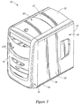
- FIGS. 1 and 2 disclose a computer 10 having an enclosure assembly with top portion 12, bottom portion 14, front portion 16, rear portion 18, left side portion 20 and right side portion 22.
- the computer may comprise a rectangular box shaped sheet metal housing 30 provided with a fixedly attached, plastic (e.g., ABS plastic) top panel member 32, bottom plastic panel member 34 and front plastic panel member 36.
- the housing 30 and relatively permanently attached panel member 32, 34, and 36 are referred to herein as the computer “chassis assembly” or simply “chassis”.
- the top panel member 32 has a top surface 40 which may have a recessed portion 42 thereon.
- An upstanding vertical post 44 may be positioned at the center of the recessed portion.
- the post is adapted for holding optical disks such as CDs and DVDs.
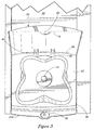
- the recessed portion also may have two other post members 46, 48 which are adapted to pivotally mount a top door (panel) member 50 about a horizontal pivot access AA, FIG. 3.
- the pivotal mounting structure of the post may be a snap-off/snap-on mounting structure of the type illustrated in FIG. 4. this structure includes having an arcuate, upwardly facing surface 52 provided at a top portion of the post which is adapted to rotably support a cylindrical pivot member 54 integrally formed with door 50.
- the post has an upper, resiliently defectable arm portion 56 adapted to engage cylindrical portion 54 to retain it in contact with arcuate portion 52 and thus maintain door 50 about pivot access AA.
- pivotal displacement of door 50 rearwardly beyond the position illustrated in FIG. 2 will cause a lower edge portion 58 of the door to contact surface 60 adjacent the post 46, 48 which in turn causes any further rotation of the door to occur along an axis defined by edge 58 at its point of contact with surface 60.
- Such further rotation causes cylindrical member 54 to be lifted up and out of its engagement with arcuate portion 52 and arm portion 56 as generally illustrated in FIG. 4 at 62.
- the defectable movement of arm portion 56 is indicated at 64.
- the cylindrical portion 54 may be snappingly reinserted into engagement with arcuate surface 52 by urging the surface of cylindrical portion 54 forwardly and downwardly against the terminal end of arm portion 56. Snap-on/snap-off doors are known in the art.
- the door 50 may have a main body portion 72 and a front edge 74 and lateral side edges 76, 78 extending generally perpendicular thereto.
- the main body portion may have a depressed and cutout portion 80 therein which may serve as a finger-hold handle for raising and lowering the door 50.
- the door may have resilient outwardly projecting numbs 82, 84 provided on the side edge portion 76, 78 thereof which are adapted to act as detents which may be received in detent holes 86 (only one shown) at the lateral edges of recessed portion 42.
- This detent assembly 82, 84, 86, etc. serves to hold the door in a normally closed operating position illustrated in FIG. 1.
- the recess 42 and the door 50 are sized to provide a relatively close fit of the door within the recessed portion.
- the recess portion at a forward edge thereof has a depression or bowl 90 which may be, e.g., 20mm in diameter, and which may have a depth of e.g., 7mm.
- the bowl 90 in turn has a hole 92 centered therein and extending through the top plastic panel 32.
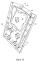
- FIG. 12 is a bottom view of top plastic panel 32 in which the portion corresponding to bowl 90 is a half dome 94 having hole 92 centered therein.
- FIG. 13 is a detail of the half dome 94 from which it may be seen that a pair of spaced apart wedge-shaped prongs 96, 98 project outwardly from the half dome 94.
- Each prong has a lower downwardly and rearwardly inclined ramp surface 110 and a vertically extending rear surface 112.
- the lower surface 120 of top plastic panel member 32 has a plurality of downwardly extending projections 122, etc. and locking tabs 124, 126, etc. adapted to snap lockingly fixedly secure the plastic top panel 32 to the top portion 128, FIG. 11, of housing 30.
- the various tabs and projections align the housing top portion with hole 92 thereof positioned directly above a point 130 on fixed front panel member 56, described below. Both point 130 and hole 92 are centered on vertical axis BB.
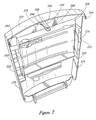
- Front plastic panel member 56 as best illustrated by FIGS. 1, 2, 5, and 11 is permanently fixedly mounted (i.e., it is not designed to be removed by a computer purchaser) on a front face portion of housing 30 as by snap-fit tabs on the panel member (not shown) received through cutouts (not shown) in the housing front face (not shown).
- the front panel 36 has a generally U-shaped configuration having a lower central body portion 140 integrally connected to left and right vertically extending arm portions 142, 144.
- Each of the arm portions as best shown by FIGS. 5 and 11, have a plurality of deflectable detent members 150, 152, 154, 156 formed on inner vertically and longitudinally extending surface portions 158, 160 thereof.
- Each of these surfaces 158, 160 also has an inwardly projecting stud 162, 164 provided in a lower surface portion thereof.
- the studs 162, 164 are coaxially aligned on horizontal axis CC.
- a resilient bridge member 170 has a first end portion 172 thereof attached to an upper end of the vertical arm portion 142 and a second end portion 174 thereof attached to an upper end of arm portion 144.
- point 130 on the bridge member lies on vertical axis BB in alignment with hole 92 in upper panel member 32.
- Bridge member 170 has two vertically upright flange portion 176, 178 provided thereon which abuttingly contact the lower front edge surface of top plastic panel member 32 when it is mounted on the housing as illustrated in FIG. 5.
- the vertical flanges 176, 178 are separated at a central portion of the bridge member 170 by a gap 180 which enables dome portion 94 to project downwardly such that the bottom most surface 93 thereof (located at the periphery at hole 92) is positioned in near touching contact, e.g., 0mm - 3mm, with a central flat surface 182 of the bridge member which contains point 130.
- Bridge member 170 is sufficiently flexible so that central portion 180 thereof may flex downwardly about 5mm as the result of moderate downward force, e.g., 10lbs., applied thereto at point 130. There is sufficient distance between the bottom of bridge member 170 and drive assemblies 190, etc. positioned immediately below it to allow such downward flexing movement to occur.
- the front panel member may also comprise a plurality of transverse portions 184, 186 defining openings 183, 185 in which other computer components such as drive assemblies, etc., 190,192 are supported.
- a front bezel member (panel) 210 may be mounted on front panel member 36 as illustrated in FIGS. 1 and 2.
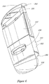
- the front bezel member as best shown in FIGS. 1, 6, and 7 includes an outside surface 212 and an inside surface 214.
- the bezel member has a top portion 216, a bottom portion 218 and left and right longitudinally extending side wall flanges 220, 222.
- the front surface portion of the front bezel 210 may have various computer actuator buttons 224, 226, etc. projecting therefrom and may have one or more openings 228, 230 extending there through for providing access to display panels, media drives, and the like.
- the inside surface of bezel 210 has an elongated latch member 232 extending rearwardly therefrom.
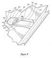
- the latch member 232 is a cantilever beam member, shown in greater detail in FIG. 8, having a first end portion 234 fixedly attached to bezel rear surface 214 at an upper portion 236 of the bezel member which is positioned above cutout slot 228.
- the latch member 232 has a second or distal end 238 having an upper surface portion 240 which is adapted to be aligned at region 241 with vertical axis BB when the bezel 210 is mounted on the housing in the position illustrated in FIG. 1.
- the second end 238 also has a lower surface portion 242 positioned immediately below its upper surface portion 240.
- a rectangular cutout 244 is provided a short distance in the proximal direction 246 from the tip 248 of second end 238. The distance from the tip may be e.g., 7mm.
- the cutout portion 244 has front, rear, left, and right annular wall portions 241, 243, 245, 247.
- the latch member 232 may have stiffening vertical flanges 252, 254 provided thereon at a position endwardly of cutout 244.
- the latch member 242 is resiliently deflectable from the position illustrated in FIGS. 7 and 8 to a position with tip end 248 located a short distance, e.g., 5mm downwardly from that illustrated in FIG. 8. Through application of moderate force e.g., 5 or 10 lbs. to upper surface portion 240.
- a central point 239 on upper surface 240 is adapted to be aligned with axis BB when the bezel 210 is in a latched position as shown in dashed lines in FIG. 13 and discussed in further detail below.
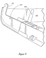
- the front bezel left and right side wall flange portions 220, 222 may comprise detent holes 260, etc. therein adapted to receive associated detent portions 150, 152, 154, etc. to releaseable hold the bezel member 210 in fixed association with the front panel member 36.
- a top claw portion 264, 266 extends rearwardly from the top lateral side portion of the bezel member 210.
- the claw portions 262, 264 are adapted to be received in recesses 266, 268 provided in the front top portion of the top panel member 32.
- Each claw portion is adapted to matingly engage a reciprocal claw portion 81, 83 provided at the lower front edge of the top door 50.
- the engagement of the reciprocal claw portions may be released by lifting the top panel door 50, but as long as the door 50 is down the claw portions remain engaged preventing forward movement of the top portion of the front bezel 210.
- the front bezel 210 has a plurality of rearward projections 268, 270, 272, 274 adapted to be received in holes 276, 278, etc., of front panel 36, FIG. 5, to properly align the bezel 210 with the front panel 36.
- the bezel member 210 also has downwardly opening, half moon shaped recesses in the lower portions of the side wall flanges 220, 222 as shown at 282, 284.
- the recesses 282, 284 are adapted to be received on studs 162, 164 for vertically supporting bezel member 210 on the front panel 36 and for allowing pivotal displacement of the front bezel 210 about axis CC.
- the operation of mounting a front bezel member 210 on front panel 36 begins, as illustrated in FIG. 10, by placing half moon recesses 282, 284 of the bezel member on studs 164 and 162 of the front panel member 36 with the bezel member 210 tilted away from the front panel 36 at an angle of between about 10 and 30 degrees.
- the top portion of the bezel member 210 is moved toward the top portion of the panel member 36 by rotation of the bezel member 210 about axis CC.
- This rotation about axis CC eventually brings latch member 232 to a point where the tip 240 thereof is positioned in alignment with a hole 310 in a vertically extending face 312 of internal computer component 190 extending through opening 183 in front panel 36.
- the hole 310 is longitudinally (forwardly/rearwardly) aligned with the gap 180 in bridge member 170. Further rotational movement of the front bezel member 210 causes the latch member tip 248 to pass through opening 310 and through gap 180 and to engage a sloping forward surface of half dome 94. The engagement with half dome 94 causes tip 248 to be moved slightly downwardly. Further rotational movement of the bezel member 210 causes tip 248 to engage ramp surfaces 110 of wedge shaped prongs 96, 98 causing further downward deflection thereof.
- the latch member 232 and other portions of the bezel member 210 and front panel member 56 and top panel member 32 are constructed and arranged such that when the latch member 232 is in the latched state the bezel member 210 is in the relatively rotated position with respect to front panel member 56 shown in FIGS. 1 and 2 with the various detents and detent holes 154, etc. and 262, etc. aligned and engaged.
- the top door 50 is opened exposing hole 92, FIG. 3.
- a small slender object such as a ball point pen, pencil, paper clip end or the like is inserted into the hole and pressed downwardly against the upper surface 240 of the latch member at 241. This downward pressure causes the latch member to deflect downwardly sufficiently so that it clears the prongs 96, 98.
- the front bezel is grasped at the top and rotated outwardly or away from the front panel member (about axis CC) until the latch member 232 is completely outside of opening 310.
- the front bezel may be lifted slightly to remove half moon portions 282, etc. from studs 164, etc. so that it now occupies the position shown in FIG. 10. Finally, it may be lifted and completely removed from the front panel.
- top door 50 may be removed simply by rotating it past the open position shown in FIG. 2.
- a computer is provided with two readily removable panel members 50, 210 (which may be a top door and front bezel) which may be replaced with other panel members of different colors to change the appearance of the computer 10.
- the door and front bezel member could be mounted directly on a sheet metal housing rather than interposed fixed plastic panel members; various latch assemblies and/or latch trip mechanisms may be employed; the top door may be eliminated or the access hole may be made large enough to, so that no tool is required, etc.
Abstract
Description
- The present invention relates generally to computers and, more particularly, to a computer having a removable/replaceable bezel.
- When personal computers were introduced in the late 1970's and early 1980's consumers considered them to be strictly utilitarian devices and their appearance reflected this sentiment. Most computers were housed in white, gray or beige, box-shaped, sheet metal housings. A few buttons and a floppy disk insertion slot were typically provided on a similarly colored, flat, front panel.
- In the last few years industrial design has become extremely important to the computer industry. For computers directed at the home consumer market, sleek housings highlighted with brightly colored plastic panels have become the norm. Peripheral devices are often sold having replaceable colored panels so that a computer owner can "customize" the peripheral by installing a colored panel to match the colored panel on his/her computer. Applicants perceive a need for a computer of a type that would allow the computer owner to customize the appearance of the computer itself. This could be done with different colored replacement panels, particularly front panels or-bezels since the front bezel is the most visible area on the computer.
- However there are drawbacks to providing a computer front bezel that is easily removable and replaceable. To begin with the front bezel is typically the region of the computer that experiences the most physical contact with a user as a result of button actuation, media insertion/removal, etc. Also the front bezel is typically one of the largest housing components and as a result of this size, any shifting or twisting of the bezel relative the rest of the housing structure can create noticeable gaps in seams or other regions where the bezel engages other portions of the computer. Another problem that exists with an easily removable bezel, applicants believe, is that it may become a target for theft or mischief. Therefore, applicants believe, any removable bezel assembly must be constructed and arranged in a manner that enables a bezel to be accurately located on the computer and reliably affixed thereto in a manner which discourages theft or mischief.
- So far as applicants are aware, prior to applicant's invention personal computers have not been provided with readily-removable/replaceable front bezels which allow computer purchasers to themselves easily customize their computers with replacement front bezels of different colors or different exterior designs. (As used herein a "readily-removable/replaceable bezel" is one which is lockingly attachable to a computer and which is unlatchingly removable and latchingly replaceable with a bezel of identical structure by a typical lay person with no special technical expertise and without specialized tools in less than 30 seconds.)
- The present invention is directed to a computer enclosure assembly which includes a readily-removable/replaceable bezel that enables a computer owner to easily change the appearance of his/her computer by replacing the bezel with one of a different color and/or different surface appearance.
- Thus the invention may comprise a computer enclosure assembly including a generally box shaped computer chassis having a plurality of face portions including a first face portion. A first panel member is removably mounted on the first face portion. The enclosure assembly with a latch assembly with a first latch portion on the chassis and a second latch portion on the first panel member. One of the first and second latch portions is trippingly deflectable to disengage the first latch portion from the second latch portion through application of pressure to a trip area. The trip area is hidden from view.
- The invention may also comprise a method of removing a computer panel including: applying pressure to a hidden trip area on a deflectable member; and removing the panel.
- The invention may also comprise a method of replacing a computer front panel including: pivotally lifting a computer top panel; inserting an elongated tool into a hole in a portion of computer chassis exposed by lifting the top panel; pushing the elongated tool against a deflectable member associated with the front panel; pivotally displacing and liftingly removing the computer front panel; placing a replacement front panel in engagement with a housing pivot structure; and pivoting the replacement front panel into latching engagement with the computer chassis.
- The invention may also comprise a computer including a computer enclosure assembly and a readily-removable/replaceable front bezel fixedly mounted on a front portion of the computer enclosure assembly.
- FIG. 1 is a perspective view of a computer;
- FIG. 2 is a perspective view of the computer of FIG. 1 with a top door in an open position;
- FIG. 3 is a top plan view of the computer of FIG. 1 with the top door in an open position;
- FIG. 4 is a perspective detail of a top door hinge assembly;
- FIG. 5 is a perspective view of a front portion the computer of FIG. 1 with a front bezel member removed;
- FIG. 6 is a front perspective view of a bezel member of the computer of FIG. 1;
- FIG. 7 is a rear perspective view of the bezel member of FIG. 6;
- FIG. 8 is a detail perspective view of a portion of a front bezel latch assembly;
- FIG. 9 is a detail perspective view of an upper corner portion of the bezel member;
- FIG. 10 is a perspective view of a front portion of the computer of FIG. 1 showing mounting of a bezel member thereon;
- FIG. 11 is a top perspective view of a front portion of the computer of FIG. 1 with a top fixed panel assembly and a front bezel member removed;
- FIG. 12 is a bottom perspective view of a top panel member of the computer of FIG. 1; and
- FIG. 13 is a detail view of a bottom portion of the top panel member shown in FIG. 12.
-
- The drawing figures, in general, disclose a computer enclosure assembly including a generally box shaped
computer chassis first face portion 36. A first panel member, which may be afront bezel 210, is removably mounted on thefirst face portion 36. A latch assembly is provided which includes afirst latch portion second latch portion 232 on thefirst panel member 210. One of the first andsecond latch portions second latch portion 232. The deflection is produced by applying pressure to atrip area 241. The trip area is hidden from view when the computer is in the normal assembled state shown in FIG. 1. The trip area may be accessed by lifting atop door 50. Pressure may be applied to the trip area with a ball point pen or straightened paper clip or other small diameter member. - FIGS. 1 and 2 disclose a
computer 10 having an enclosure assembly withtop portion 12,bottom portion 14,front portion 16,rear portion 18,left side portion 20 andright side portion 22. - The computer may comprise a rectangular box shaped
sheet metal housing 30 provided with a fixedly attached, plastic (e.g., ABS plastic)top panel member 32, bottomplastic panel member 34 and frontplastic panel member 36. Thehousing 30 and relatively permanently attachedpanel member - The
top panel member 32 has a top surface 40 which may have arecessed portion 42 thereon. An upstandingvertical post 44 may be positioned at the center of the recessed portion. The post is adapted for holding optical disks such as CDs and DVDs. The recessed portion also may have two otherpost members member 50 about a horizontal pivot access AA, FIG. 3. The pivotal mounting structure of the post may be a snap-off/snap-on mounting structure of the type illustrated in FIG. 4. this structure includes having an arcuate, upwardly facingsurface 52 provided at a top portion of the post which is adapted to rotably support acylindrical pivot member 54 integrally formed withdoor 50. The post has an upper, resilientlydefectable arm portion 56 adapted to engagecylindrical portion 54 to retain it in contact witharcuate portion 52 and thus maintaindoor 50 about pivot access AA. However, pivotal displacement ofdoor 50 rearwardly beyond the position illustrated in FIG. 2 will cause alower edge portion 58 of the door to contactsurface 60 adjacent thepost edge 58 at its point of contact withsurface 60. Such further rotation causescylindrical member 54 to be lifted up and out of its engagement witharcuate portion 52 andarm portion 56 as generally illustrated in FIG. 4 at 62. The defectable movement ofarm portion 56 is indicated at 64. Thecylindrical portion 54 may be snappingly reinserted into engagement witharcuate surface 52 by urging the surface ofcylindrical portion 54 forwardly and downwardly against the terminal end ofarm portion 56. Snap-on/snap-off doors are known in the art. - The
door 50 may have amain body portion 72 and afront edge 74 andlateral side edges cutout portion 80 therein which may serve as a finger-hold handle for raising and lowering thedoor 50. The door may have resilient outwardly projectingnumbs side edge portion portion 42. Thisdetent assembly recess 42 and thedoor 50 are sized to provide a relatively close fit of the door within the recessed portion. As best shown in FIG. 3 the recess portion at a forward edge thereof has a depression orbowl 90 which may be, e.g., 20mm in diameter, and which may have a depth of e.g., 7mm. Thebowl 90 in turn has ahole 92 centered therein and extending through the topplastic panel 32. FIG. 12 is a bottom view of topplastic panel 32 in which the portion corresponding to bowl 90 is ahalf dome 94 havinghole 92 centered therein. FIG. 13 is a detail of thehalf dome 94 from which it may be seen that a pair of spaced apart wedge-shapedprongs half dome 94. Each prong has a lower downwardly and rearwardlyinclined ramp surface 110 and a vertically extendingrear surface 112. It may be seen from FIG. 12 that thelower surface 120 of topplastic panel member 32 has a plurality of downwardly extendingprojections 122, etc. and lockingtabs top panel 32 to thetop portion 128, FIG. 11, ofhousing 30. The various tabs and projections align the housing top portion withhole 92 thereof positioned directly above apoint 130 on fixedfront panel member 56, described below. Bothpoint 130 andhole 92 are centered on vertical axis BB. - Front
plastic panel member 56, as best illustrated by FIGS. 1, 2, 5, and 11 is permanently fixedly mounted (i.e., it is not designed to be removed by a computer purchaser) on a front face portion ofhousing 30 as by snap-fit tabs on the panel member (not shown) received through cutouts (not shown) in the housing front face (not shown). Thefront panel 36 has a generally U-shaped configuration having a lowercentral body portion 140 integrally connected to left and right vertically extendingarm portions deflectable detent members surface portions surfaces stud studs resilient bridge member 170 has afirst end portion 172 thereof attached to an upper end of thevertical arm portion 142 and asecond end portion 174 thereof attached to an upper end ofarm portion 144. As previously mentionedpoint 130 on the bridge member lies on vertical axis BB in alignment withhole 92 inupper panel member 32.Bridge member 170 has two verticallyupright flange portion plastic panel member 32 when it is mounted on the housing as illustrated in FIG. 5. Thevertical flanges bridge member 170 by agap 180 which enablesdome portion 94 to project downwardly such that the bottommost surface 93 thereof (located at the periphery at hole 92) is positioned in near touching contact, e.g., 0mm - 3mm, with a centralflat surface 182 of the bridge member which containspoint 130.Bridge member 170 is sufficiently flexible so thatcentral portion 180 thereof may flex downwardly about 5mm as the result of moderate downward force, e.g., 10lbs., applied thereto atpoint 130. There is sufficient distance between the bottom ofbridge member 170 and driveassemblies 190, etc. positioned immediately below it to allow such downward flexing movement to occur. - The front panel member may also comprise a plurality of
transverse portions openings - A front bezel member (panel) 210 may be mounted on
front panel member 36 as illustrated in FIGS. 1 and 2. The front bezel member, as best shown in FIGS. 1, 6, and 7 includes anoutside surface 212 and aninside surface 214. The bezel member has atop portion 216, abottom portion 218 and left and right longitudinally extendingside wall flanges front bezel 210 may have variouscomputer actuator buttons more openings - The inside surface of
bezel 210 has an elongatedlatch member 232 extending rearwardly therefrom. Thelatch member 232 is a cantilever beam member, shown in greater detail in FIG. 8, having afirst end portion 234 fixedly attached to bezelrear surface 214 at anupper portion 236 of the bezel member which is positioned abovecutout slot 228. Thelatch member 232 has a second ordistal end 238 having anupper surface portion 240 which is adapted to be aligned atregion 241 with vertical axis BB when thebezel 210 is mounted on the housing in the position illustrated in FIG. 1. Thesecond end 238 also has alower surface portion 242 positioned immediately below itsupper surface portion 240. Arectangular cutout 244 is provided a short distance in theproximal direction 246 from thetip 248 ofsecond end 238. The distance from the tip may be e.g., 7mm. Thecutout portion 244 has front, rear, left, and rightannular wall portions latch member 232 may have stiffeningvertical flanges cutout 244. Thelatch member 242 is resiliently deflectable from the position illustrated in FIGS. 7 and 8 to a position withtip end 248 located a short distance, e.g., 5mm downwardly from that illustrated in FIG. 8. Through application of moderate force e.g., 5 or 10 lbs. toupper surface portion 240. Acentral point 239 onupper surface 240 is adapted to be aligned with axis BB when thebezel 210 is in a latched position as shown in dashed lines in FIG. 13 and discussed in further detail below. - As illustrated in FIG. 9 the front bezel left and right side
wall flange portions detent portions bezel member 210 in fixed association with thefront panel member 36. As also shown in FIG. 9 atop claw portion bezel member 210. Theclaw portions recesses top panel member 32. Each claw portion is adapted to matingly engage a reciprocal claw portion 81, 83 provided at the lower front edge of thetop door 50. The engagement of the reciprocal claw portions may be released by lifting thetop panel door 50, but as long as thedoor 50 is down the claw portions remain engaged preventing forward movement of the top portion of thefront bezel 210. Thefront bezel 210 has a plurality ofrearward projections holes front panel 36, FIG. 5, to properly align thebezel 210 with thefront panel 36. - The
bezel member 210 also has downwardly opening, half moon shaped recesses in the lower portions of theside wall flanges recesses 282, 284 are adapted to be received onstuds bezel member 210 on thefront panel 36 and for allowing pivotal displacement of thefront bezel 210 about axis CC. - The operation of mounting a
front bezel member 210 onfront panel 36 begins, as illustrated in FIG. 10, by placing half moon recesses 282, 284 of the bezel member onstuds front panel member 36 with thebezel member 210 tilted away from thefront panel 36 at an angle of between about 10 and 30 degrees. Next the top portion of thebezel member 210 is moved toward the top portion of thepanel member 36 by rotation of thebezel member 210 about axis CC. This rotation about axis CC eventually bringslatch member 232 to a point where thetip 240 thereof is positioned in alignment with ahole 310 in a vertically extendingface 312 ofinternal computer component 190 extending throughopening 183 infront panel 36. Thehole 310 is longitudinally (forwardly/rearwardly) aligned with thegap 180 inbridge member 170. Further rotational movement of thefront bezel member 210 causes thelatch member tip 248 to pass throughopening 310 and throughgap 180 and to engage a sloping forward surface ofhalf dome 94. The engagement withhalf dome 94 causes tip 248 to be moved slightly downwardly. Further rotational movement of thebezel member 210 causestip 248 to engageramp surfaces 110 of wedge shapedprongs bezel member 210 about axis CC causes thelatch member cutout 240 to move into vertical alignment with the prongs which allows the latch member to resiliently deflect upwardly such that the upper surface thereof is in contact with thelower surface 93 ofdome portion 94 as illustrated in phantom in FIG. 13. In this position thelatch member 232 is in a "latched state" or "latched" and is prevented from moving longitudinally forwardly by the engagement of therear surface 112 of theprongs annular wall surface 241 of the cutout. - The
latch member 232 and other portions of thebezel member 210 andfront panel member 56 andtop panel member 32 are constructed and arranged such that when thelatch member 232 is in the latched state thebezel member 210 is in the relatively rotated position with respect tofront panel member 56 shown in FIGS. 1 and 2 with the various detents anddetent holes 154, etc. and 262, etc. aligned and engaged. - To remove the
bezel member 210 thetop door 50 is opened exposinghole 92, FIG. 3. Next a small slender object such as a ball point pen, pencil, paper clip end or the like is inserted into the hole and pressed downwardly against theupper surface 240 of the latch member at 241. This downward pressure causes the latch member to deflect downwardly sufficiently so that it clears theprongs latch member 232 the front bezel is grasped at the top and rotated outwardly or away from the front panel member (about axis CC) until thelatch member 232 is completely outside ofopening 310. Next, the front bezel may be lifted slightly to removehalf moon portions 282, etc. fromstuds 164, etc. so that it now occupies the position shown in FIG. 10. Finally, it may be lifted and completely removed from the front panel. - As previously mentioned the
top door 50 may be removed simply by rotating it past the open position shown in FIG. 2. - Thus, a computer is provided with two readily
removable panel members 50, 210 (which may be a top door and front bezel) which may be replaced with other panel members of different colors to change the appearance of thecomputer 10. - While illustrative and presently preferred embodiments of the invention have been described in detail herein, it is to be understood that the inventive concepts may be otherwise variously embodied and employed and that the appended claims are intended to be construed to include such variations except insofar as limited by the prior art. For example, the door and front bezel member could be mounted directly on a sheet metal housing rather than interposed fixed plastic panel members; various latch assemblies and/or latch trip mechanisms may be employed; the top door may be eliminated or the access hole may be made large enough to, so that no tool is required, etc.
Claims (14)
- A computer enclosure assembly comprising:a generally box shaped computer chassis (30-36) having a plurality of face portions including a first face portion;a first panel member (210) removably mounted on said first face portion;a latch assembly comprising a first latch portion (96, 98) on said chassis and a second latch portion (232) on said first panel member;one of said first and second latch portions being trippingly deflectable to disengage said first latch portion from said second latch portion through application of pressure to a trip area (241), said trip area being hidden from view.
- The computer enclosure assembly of claim 1, said trip area being hidden behind a displaceable second panel member (50).
- The computer enclosure assembly of claim 2, said second displaceable panel member (50) being mounted on one of said face portions (32) of said chassis contiguous with said first face portion.
- The computer enclosure assembly of claim 3, said first face portion (36) comprising a front face portion, said second face portion (32) comprising a top face portion.
- The computer enclosure assembly of any preceding claim, said trip area (241) being engageable only through use of a tool.
- The computer enclosure assembly of any preceding claim, said trip area (241) being engageable only through use of an elongated tool insertable through a hole (92) in said chassis.
- The computer enclosure assembly of any preceding claim, further comprising:a pivot assembly comprising a first pivot assembly portion on said chassis (162, 164) and a second pivot assembly portion (282, 284) on said first panel member cooperating with said first pivot assembly portion to removably pivotally support said first panel member on said first face portion;said first panel member having said second latch portion provided at a first end portion thereof and having said second pivot assembly portion provided on a second end portion thereof.
- The computer enclosure assembly of claim 7, wherein said first panel portion comprises a first section and a second section pivotally mounted on said first section; said first section having said second latch portion and said second pivot assembly portion provided thereon.
- The computer enclosure assembly of any preceding claim, further comprising a replacement panel identical to said first panel in size and shape.
- A method of removing a computer panel comprising:applying pressure to a hidden trip area on a deflectable member; andremoving said panel.
- The method of claim 10 wherein applying pressure to a hidden trip area on a deflectable member comprises applying pressure with an elongated tool, and the method further comprises inserting the elongated tool through a restricted opening in a computer chassis prior to applying pressure to the hidden trip area.
- A method of replacing a computer front panel comprising:
pivotally lifting a computer top panel:inserting an elongated tool into a hole in a portion of computer chassis exposed by lifting the top panel;pushing the elongated tool against a deflectable member associated with the front panel;pivotally displacing and liftingly removing the computer front panel;placing a replacement front panel in engagement with a housing pivot structure;pivoting the replacement front panel into latching engagement with the computer chassis. - A computer comprising:a computer enclosure assembly; anda readily-removable/replaceable front bezel fixedly mounted on a front portion of said computer enclosure assembly.
- The computer of claim 13 further comprising a readily-removable top door mounted on a top portion of said enclosure assembly, a front bezel latching assembly positioned below said top door and accessible by opening said top door, and a latch access opening positioned below said door and having a diameter less than 10mm.
Applications Claiming Priority (2)
| Application Number | Priority Date | Filing Date | Title |
|---|---|---|---|
| US09/586,650 US6535379B1 (en) | 2000-06-01 | 2000-06-01 | Computer with exchangeable front bezel |
| US586650 | 2000-06-01 |
Publications (2)
| Publication Number | Publication Date |
|---|---|
| EP1164459A2 true EP1164459A2 (en) | 2001-12-19 |
| EP1164459A3 EP1164459A3 (en) | 2003-05-07 |
Family
ID=24346597
Family Applications (1)
| Application Number | Title | Priority Date | Filing Date |
|---|---|---|---|
| EP01304832A Withdrawn EP1164459A3 (en) | 2000-06-01 | 2001-06-01 | Computer panel member |
Country Status (4)
| Country | Link |
|---|---|
| US (1) | US6535379B1 (en) |
| EP (1) | EP1164459A3 (en) |
| CN (1) | CN1350217A (en) |
| TW (1) | TW509836B (en) |
Families Citing this family (16)
| Publication number | Priority date | Publication date | Assignee | Title |
|---|---|---|---|---|
| US6490151B1 (en) * | 2000-08-25 | 2002-12-03 | Crystal Group Inc. | Method and system for visually differentiating industrial personal computers |
| US6685285B1 (en) * | 2001-05-10 | 2004-02-03 | The Mills Company Inc. | Latch mechanism for locker |
| US7699412B2 (en) * | 2001-05-10 | 2010-04-20 | The Mills Company Inc. | Storage unit |
| US6707667B1 (en) * | 2002-09-19 | 2004-03-16 | Kuo-Yao Yang | Integral computer |
| KR20040082515A (en) * | 2003-03-19 | 2004-09-30 | 엘지전자 주식회사 | Structure for cap deco of refrigerator |
| TW587747U (en) * | 2003-04-09 | 2004-05-11 | Hon Hai Prec Ind Co Ltd | Bezel mounting assembly |
| JP2005070970A (en) * | 2003-08-21 | 2005-03-17 | Toshiba Corp | Electronic equipment |
| KR100475578B1 (en) * | 2003-08-22 | 2005-03-14 | 삼성전자주식회사 | Computer |
| US20050045501A1 (en) * | 2003-09-02 | 2005-03-03 | Briggs Randall Jay | Integrated compact disc holder for a portable device |
| US7505260B2 (en) * | 2004-03-12 | 2009-03-17 | Hewlett-Packard Development Company, L.P. | Storage compartment with positionable post for holding a compact disc and related system and method |
| US20050278301A1 (en) * | 2004-05-26 | 2005-12-15 | Castellanos Maria G | System and method for determining an optimized process configuration |
| JP4533712B2 (en) * | 2004-09-30 | 2010-09-01 | 株式会社東芝 | Electronics |
| US7431408B2 (en) * | 2006-03-15 | 2008-10-07 | In Win Development, Inc. | Movable cover-plate of a computer host |
| US7697282B2 (en) * | 2007-04-05 | 2010-04-13 | Dell Products L.P. | Tip-resisting stand for floor standing chassis |
| US20090127988A1 (en) * | 2007-11-20 | 2009-05-21 | Sergejs Lucuks | Device for a computer case cover |
| CN104571374B (en) * | 2013-10-21 | 2017-11-21 | 纬创资通股份有限公司 | Electronic installation with rotational positioning function |
Citations (6)
| Publication number | Priority date | Publication date | Assignee | Title |
|---|---|---|---|---|
| EP0508869A2 (en) * | 1991-04-08 | 1992-10-14 | Digital Equipment Corporation | Shielded printed circuit board housing for high density storage |
| US5202197A (en) * | 1991-10-17 | 1993-04-13 | International Business Machines Corporation | Data processing device having an improved manually operated battery eject mechanism and a warning light |
| US5423605A (en) * | 1993-05-14 | 1995-06-13 | Enlight Corporation | Front panel structure for a personal computer |
| US5547272A (en) * | 1995-04-24 | 1996-08-20 | At&T Global Information Solutions Company | Modular cabinet bezel |
| US5877938A (en) * | 1995-08-22 | 1999-03-02 | Sequent Computer Systems, Inc. | Packaging architecture for a data server |
| US5997115A (en) * | 1997-10-08 | 1999-12-07 | Dell U.S.A., L.P. | Computer access panel having single point release interlock mechanism |
Family Cites Families (3)
| Publication number | Priority date | Publication date | Assignee | Title |
|---|---|---|---|---|
| US6640235B1 (en) * | 1992-08-20 | 2003-10-28 | Intel Corporation | Expandable mass disk drive storage system |
| US5349132A (en) * | 1993-02-08 | 1994-09-20 | Apple Computer, Inc. | Methods and apparatus for modular computer construction |
| US6053586A (en) * | 1997-10-24 | 2000-04-25 | Dell U.S.A., L.P. | Computer access panel having a biased cover latching mechanism and method |
-
2000
- 2000-06-01 US US09/586,650 patent/US6535379B1/en not_active Expired - Fee Related
-
2001
- 2001-05-31 TW TW090113229A patent/TW509836B/en not_active IP Right Cessation
- 2001-06-01 CN CN01120737.XA patent/CN1350217A/en active Pending
- 2001-06-01 EP EP01304832A patent/EP1164459A3/en not_active Withdrawn
Patent Citations (6)
| Publication number | Priority date | Publication date | Assignee | Title |
|---|---|---|---|---|
| EP0508869A2 (en) * | 1991-04-08 | 1992-10-14 | Digital Equipment Corporation | Shielded printed circuit board housing for high density storage |
| US5202197A (en) * | 1991-10-17 | 1993-04-13 | International Business Machines Corporation | Data processing device having an improved manually operated battery eject mechanism and a warning light |
| US5423605A (en) * | 1993-05-14 | 1995-06-13 | Enlight Corporation | Front panel structure for a personal computer |
| US5547272A (en) * | 1995-04-24 | 1996-08-20 | At&T Global Information Solutions Company | Modular cabinet bezel |
| US5877938A (en) * | 1995-08-22 | 1999-03-02 | Sequent Computer Systems, Inc. | Packaging architecture for a data server |
| US5997115A (en) * | 1997-10-08 | 1999-12-07 | Dell U.S.A., L.P. | Computer access panel having single point release interlock mechanism |
Also Published As
| Publication number | Publication date |
|---|---|
| EP1164459A3 (en) | 2003-05-07 |
| CN1350217A (en) | 2002-05-22 |
| TW509836B (en) | 2002-11-11 |
| US6535379B1 (en) | 2003-03-18 |
Similar Documents
| Publication | Publication Date | Title |
|---|---|---|
| US6535379B1 (en) | Computer with exchangeable front bezel | |
| US6373690B1 (en) | Apparatus for mounting a panel to a chassis of a computer | |
| US6266239B1 (en) | Computer access panel having a biased cover latching mechanism and method | |
| JP3077378B2 (en) | Input pen storage mechanism for tablet input device | |
| US6882527B2 (en) | Computer enclosure incorporating drive bracket | |
| CN101311875B (en) | CD ROM baffle plate combination | |
| JP3601720B2 (en) | Compact disc case | |
| US8230629B2 (en) | Faceplate assembly and label cover | |
| US6466435B2 (en) | Computer bezel having pivotable drive cover | |
| JPH11249758A (en) | Card holder and information processor having the same | |
| US20070235305A1 (en) | Bezel assembly for computer | |
| JP5035828B2 (en) | Display holder | |
| JP4192058B2 (en) | Handle hole cover for chassis for gaming machines | |
| US6502439B1 (en) | Storage lock mechanism | |
| US7247806B2 (en) | Computing device bezel and facia button therefor | |
| JPH0576434A (en) | Wagon | |
| US20040031899A1 (en) | Device for holding an object | |
| JPH09139583A (en) | Connection structure for cover | |
| JP4352020B2 (en) | Panel attaching / detaching mechanism, disc reproducing apparatus and panel jig using the panel attaching / detaching mechanism. | |
| JP4201480B2 (en) | Wall material attachment and wall material attachment structure using the wall material attachment | |
| JP2802038B2 (en) | Display device | |
| JP2000027518A (en) | Handle mechanism | |
| JPH0720793Y2 (en) | Product sales data processor | |
| JPH07235A (en) | Wiring through-hole device of desk top plate or the like | |
| JPH0355376Y2 (en) |
Legal Events
| Date | Code | Title | Description |
|---|---|---|---|
| PUAI | Public reference made under article 153(3) epc to a published international application that has entered the european phase |
Free format text: ORIGINAL CODE: 0009012 |
|
| AK | Designated contracting states |
Kind code of ref document: A2 Designated state(s): AT BE CH CY DE DK ES FI FR GB GR IE IT LI LU MC NL PT SE TR |
|
| AX | Request for extension of the european patent |
Free format text: AL;LT;LV;MK;RO;SI |
|
| PUAL | Search report despatched |
Free format text: ORIGINAL CODE: 0009013 |
|
| AK | Designated contracting states |
Designated state(s): AT BE CH CY DE DK ES FI FR GB GR IE IT LI LU MC NL PT SE TR |
|
| AX | Request for extension of the european patent |
Extension state: AL LT LV MK RO SI |
|
| 17P | Request for examination filed |
Effective date: 20030804 |
|
| AKX | Designation fees paid |
Designated state(s): FR GB |
|
| REG | Reference to a national code |
Ref country code: DE Ref legal event code: 8566 |
|
| 17Q | First examination report despatched |
Effective date: 20040910 |
|
| STAA | Information on the status of an ep patent application or granted ep patent |
Free format text: STATUS: THE APPLICATION IS DEEMED TO BE WITHDRAWN |
|
| 18D | Application deemed to be withdrawn |
Effective date: 20080103 |