EP1170879A1 - Radio receiving device and radio receiving method - Google Patents
Radio receiving device and radio receiving method Download PDFInfo
- Publication number
- EP1170879A1 EP1170879A1 EP20010901376 EP01901376A EP1170879A1 EP 1170879 A1 EP1170879 A1 EP 1170879A1 EP 20010901376 EP20010901376 EP 20010901376 EP 01901376 A EP01901376 A EP 01901376A EP 1170879 A1 EP1170879 A1 EP 1170879A1
- Authority
- EP
- European Patent Office
- Prior art keywords
- signals
- replica
- radio receiving
- weighting factors
- arrival
- Prior art date
- Legal status (The legal status is an assumption and is not a legal conclusion. Google has not performed a legal analysis and makes no representation as to the accuracy of the status listed.)
- Withdrawn
Links
Images


Classifications
-
- H—ELECTRICITY
- H04—ELECTRIC COMMUNICATION TECHNIQUE
- H04B—TRANSMISSION
- H04B7/00—Radio transmission systems, i.e. using radiation field
- H04B7/02—Diversity systems; Multi-antenna system, i.e. transmission or reception using multiple antennas
- H04B7/04—Diversity systems; Multi-antenna system, i.e. transmission or reception using multiple antennas using two or more spaced independent antennas
- H04B7/08—Diversity systems; Multi-antenna system, i.e. transmission or reception using multiple antennas using two or more spaced independent antennas at the receiving station
- H04B7/0837—Diversity systems; Multi-antenna system, i.e. transmission or reception using multiple antennas using two or more spaced independent antennas at the receiving station using pre-detection combining
- H04B7/0842—Weighted combining
- H04B7/086—Weighted combining using weights depending on external parameters, e.g. direction of arrival [DOA], predetermined weights or beamforming
-
- H—ELECTRICITY
- H01—ELECTRIC ELEMENTS
- H01Q—ANTENNAS, i.e. RADIO AERIALS
- H01Q3/00—Arrangements for changing or varying the orientation or the shape of the directional pattern of the waves radiated from an antenna or antenna system
- H01Q3/26—Arrangements for changing or varying the orientation or the shape of the directional pattern of the waves radiated from an antenna or antenna system varying the relative phase or relative amplitude of energisation between two or more active radiating elements; varying the distribution of energy across a radiating aperture
- H01Q3/2605—Array of radiating elements provided with a feedback control over the element weights, e.g. adaptive arrays
- H01Q3/2611—Means for null steering; Adaptive interference nulling
- H01Q3/2617—Array of identical elements
Definitions
- the present invention relates to a radio receiving apparatus and a radio receiving method used in a mobile communication system of CDMA (Code Division Multiple Access).
- CDMA Code Division Multiple Access
- a signal that a radio receiving apparatus receives is subjected to interference by various signals to cause deterioration of characteristics.
- An array antenna is known as an apparatus for eliminating the interference.
- the array antenna is composed of a plurality of antenna elements, and is capable of setting reception directivity freely by providing adjustment of each of amplitude and phase to a signal received by each antenna element.
- adjustment of amplitude and phase provided to the received signal can be carried out by multiplying the received signal by weighting factor (hereinafter referred to as "reception weight").
- the radio receiving apparatus can intensively receive only a signal coming from a desired direction by adjusting the reception weight by which the received signal is multiplied.
- the interference canceller is a technique for canceling a signal (interference) transmitted from other communication partners other than current communication partner from the received signal to extract a desired signal from the received signal.
- an apparatus for canceling interference signals there are apparatuses described in 1) "Sequential Channel Estimation Type Serial Canceller Using a pilot Symbol in DS-CDMA (Technical Bulletin, RCS95-50, July, 1995, Radio Communication System Research Society of the Institute of Electronics, Information and Communication Engineers)" authored by Sawahashi, Miki, Andoh, and Higuchi, 2) “Sequential Transmission Line Estimation Type CDMA Multistage Interference Canceller Utilizing a Symbol Replica Process (Technical Bulletin, RCS96-171, February, 1997, Radio Communication System Research Society of the Institute of Electronics, Information and Communication Engineers)” authored by Yoshida and Ushirokawa, and 3) "Study of CDMA Interference Canceller in an Up
- It is an object of the present invention is to provide a radio receiving apparatus and a radio receiving method that are capable of receiving a desired signal with high quality in an apparatus of small scale without providing an interference canceller to each channel corresponding to each communication partner even when the array antenna and the interference canceller are combined.
- the present invention generates a replica signal every signal received by each antenna of the array antenna to make it possible to receive a desired signal with high quality in an apparatus of small scale without providing an interference canceller to each channel corresponding to each communication partner even when the array antenna and the interference canceller are combined.
- the present invention is characterized in that a reception weight by which an optimal radiation pattern is formed is calculated to improve an interference cancellation effect without limiting to a calculation algorithm of the reception weight. Moreover, the present invention is characterized in that the reception weight is sequentially updated using a signal from which a interference signal is sequentially eliminated to sequentially generate a radiation pattern with high reliability, whereby further improving the interference cancellation effect.
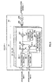
- FIG. 1 is a block diagram of a main part illustrating a schematic configuration of a radio receiving apparatus according to Embodiment 1 of the present invention.
- the following will explain the case in which the number of stages of the interference canceller is 3, the number of communication partners is 3, and the number of multipaths is 3. It is noted that these numbers are just one example, and this Embodiment is not limited to these number.
- a signal received via an antenna 101-1 is inputted to ICUs (Interference Canceling Units) 102-1 to 102-3 and a delayer 103-1 provided to correspond to the antenna 101-1.
- ICUs Interference Canceling Units
- a signal received via an antenna 101-2 is inputted to ICUs 102-1 to 102-3 and a delayer 103-2 provided to correspond to the antenna 101-2.
- ICUs 102-1 to 102-3 are provided to correspond to communication partners 1 to 3, respectively, and each generates a replica signal in connection with each of the signals received via the antennas 101-1 and 101-2.
- the replica signals generated by the ICUs 102-1 to 102-3 are inputted to adders 104-1 and 104-2 provided to correspond to the antennas 101-1 and 101-2, and are inputted to adders 105-1 and 105-2.
- the configuration of each of the ICUs 102-1 to 102-3 will be described later.
- the delayers 103-1 and 103-2 delay the received signals by processing time of ICUs 102-1 to 102-3, and each outputs the resultant to each of the adders 104-1 and 104-2.
- the replica signals of communication partners 1 to 3 for the signal received via the antenna 101-1 are subtracted from the signal received via the antenna 101-1.
- the replica signals of communication partners 1 to 3 for the signal received via the antenna 101-2 are subtracted from the signal received via the antenna 101-2. This eliminates the replica signals of all communication partners from the signals received via the respective antennas. Signals (residual signals) obtained by eliminating the replica signals of all communication partners from the received signals are inputted to the adders 105-1 and 105-2, respectively, and are inputted to the delayers 103-1 and 103-2 of the second stage.
- the replica signals for the signals received via the antennas 101-1 and 101-2 and the residual signals are added every communication partner.
- the signal from communication partner 2 and the signal from communication partner 3, which cause interference with communication partner 1 are eliminated from the received signal to obtain a desired signal for communication partner 1 every antenna.
- the similar processing is carried out, so that the signals of other communication partners causing interference are eliminated from the received signals, so that the desired signal for communication partner 2 and the desired signal for communication partner 3 can be obtained every antenna.
- the obtained desired signals are inputted to ICUs 102-1 to 102-3 of the second stage, respectively.
- the same processing as performed in the first stage is repeated in the second stage, so that the accuracy of replica signal is improved and that of the interference signal cancellation is improved.
- the more the number of stages are increased the more the inference signals sent from the other communication partners that cause interference with the respective communication partners are eliminated.
- the signals added by the adders 105-1 and 105-2 of the second stage are inputted to ICUs 106-1 to 106-3 of the third stage, and are demodulated. This obtains demodulated signals 1 to 3 of the communication partners 1 to 3.
- the configuration of each of the ICUs 106-1 to 106-3 will be described later.
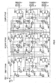
- FIG. 2 is a block diagram of a main part illustrating a schematic configuration of ICU of each of first and second stages of an interference signal canceling apparatus according to Embodiment 1 of the present invention.
- FIG. 3 is a block diagram of a main part illustrating a schematic configuration of ICU of a third stage of the interference signal canceling apparatus according to Embodiment 1 of the present invention.
- ICUs 102-1 to 102-3 of the first and second stages have the same configuration and operation, respectively.
- ICUs 106-1 to 106-3 of the third stage have the same configuration and operation.
- the ICU 102-1 of the first stage and the ICU 106-1 of the third stage corresponding to the communication partner 1 are explained, and the explanation of the respective ICUs corresponding to the communication partner 2 and the communication partner 3 is omitted.
- the ICU 102-1 shown in FIG. 2 and the ICU 106-1 shown in FIG. 3 are configured on the assumption that the number of multipath to the radio receiving apparatus is 3.
- the respective configuration parts for the respective paths are shown by P1 to P3, respectively. Since the respective configuration parts for the respective paths have the same configuration and operation, only the first path P1 is illustrated, and the explanation of the second path P2 and third path P3 is omitted.
- the ICU 102-1 briefly includes a preceding stage S1 in which the signals received by the respective antennas 101-1 and 101-2 are subjected to despreading and then the resultants are multiplied by reception weights of the receptive antennas, respectively, an intermediate stage S2 in which RAKE combining and provisional decision are carried out, and the last stage S3 in which the signal subjected to provisional decision is multiplied by a weighting factor for generating a replica signal (hereinafter referred to as "replica weight") to generate a replica signal.
- replica weight a weighting factor for generating a replica signal
- the signal received via the antenna 101-1 is despread by a despreading section 201-1 and the signal received via the antenna 101-2 is despread by a despreading section 201-2.
- Despread signals X 1 and X 2 are inputted to multipliers 202-1, 202-2, a reception weight calculation section 203, and an arrival direction estimation section 204.
- the reception weight calculation section 203 calculates weights W 1 and W 2 of each antenna, and outputs the resultants to multipliers 202-1 and 202-2, and a replica weight calculation section 211. Since the reception weight calculation section 203 is provided every path and every communication partner, making it possible to calculate the reception weights each being different every path and every user. The calculation method for the reception weight will be described later.
- the arrival direction estimation section 204 estimates a direction of arrival of the received signal every antenna, and outputs steering vectors S 1 and S 2 of the respective antennas to the replica weight calculation section 211, and the arrival direction estimation section 204 of the second stage.
- the reason why the arrival direction estimation section 204 of the first stage outputs the steering vectors S 1 and S 2 to the arrival direction estimation section 204 of the second stage is as follows. Specifically, the arrival direction estimation section 204 of the second stage averages the steering victors calculated in the first stage and the steering victors calculated in the second stage every path, and uses the resultant as a steering vector in the second stage. This makes it possible to increase the accuracy of the steering vector as the operation goes to the last stage. In other words, the accuracy of the direction of arrival can be improved as the operation goes to the last stage, making it possible to improve the accuracy of the calculation of the replica weight.
- the signal inputted to each stage is a signal from which an interference signal is eliminated in the previous stage, the signal whose interference state changes every stage is inputted.
- the reception weight calculation section 203 and the arrival direction estimation section 204 are provided on a stage-by-stage basis. This makes it possible to adaptively change the radiation pattern in accordance with the state of the inference signal at this point on the stage-by-stage basis.
- the radiation pattern and the replica signal can be accurately generated. This eliminates the useless processing wherein interference cancellation using directional control is further performed to interference that can be sufficiently cancelled by only interference cancellation processing, conversely; interference cancellation processing is further performed to interference that can be sufficiently cancelled by only directional control.
- the direction of arrival of the signal from which the interference signals are sequentially cancelled is estimated.
- the accuracy of estimation of the direction of arrival is improved as the operation goes to the last stage. Accordingly, since the interference cancellation having good performance can be carried out with a relatively small number of stages, the apparatus scale can be reduced.
- the channel estimation section 206 performs the channel estimation based on the signal subjected to the array combining, and outputs the resultant to a complex conjugate h a * of a channel estimation value h a to the multiplier 207, and outputs the channel estimation value h a to a multiplier 210.
- the multiplier 207 multiplies the signal subjected to the array combining by the complex conjugate h a * of the channel estimation value. This compensates for phase rotation of the signal subjected to the array combining.
- the signal which has been subjected to the array combining of each of paths P1 to P3 and which has been multiplied by the complex conjugate h a * of the channel estimation value, is subjected to RAKE combining by an adder 208 of the intermediate stage S2.
- the result obtained by RAKE combining is temporarily decided by a decider 209.
- a signal d subjected to temporarily decision is multiplied by the channel estimation value h a by a multiplier 210 for each of paths P1 to P3, and the resultant is inputted to multipliers 212-1 and 212-2, respectively.
- a replica weight calculation section 211 calculates replica weights W r1 and W r2 using reception weights W 1 and W 2 and steering vectors S 1 and S 2 , and outputs the resultant to the multipliers 212-1 and 212-2, respectively. The method for calculating the replica weight will be described later.
- the multipliers 212-1 and 212-2 multiply the signals outputted from the multiplier 210 by replica weights W r1 and W r2 , respectively. This obtains replica signals X r1 and X r2 corresponding to X 1 and X 2 , respectively.
- the replica signals Xr 1 and Xr 2 are spread by re-spreading sections 213-1 and 213-2, respectively, and the resultants are inputted to adders 214-1 and 214-2.
- the replica signals Xr 1 and Xr 2 re-spread for each of paths P1 to P3 are added by adders 214-1 and 214-2, respectively, and the resultants are inputted to adders 105-1 and 105-2.
- the ICU 106-1 of the third stage will be described.
- the ICU 106-1 of the third stage has substantially the same structure as that of the preceding stage S1 and that of the intermediate stage S2 of the ICU 102-1 of FIG. 2. Accordingly, the same reference numerals are added to the same configuration parts as those of the ICU102-1 of FIG. 2, and the explanation of the ICU 106-1 of the third stage will be omitted.
- the ICU 106-1 is different from the ICU 102-1 in the point that there is no the arrival direction estimation section 204 provided in the ICU 102-1. This is because in the third stage, demodulated signal 1 is outputted instead of the replica signal, and therefore the replica weight necessary for generating the replica signals not required, whereby steering vector necessary for calculating the replica weight is not required also.
- the method of directional control using the array antenna is largely divided into directional control carried out by a beam steering and directional control carried out by a null steering.
- the beam steering is a method in which interference from the other communication partners is eliminated by generating such a radiation pattern that directs directivity to a direction where a desired communication partner exists.
- the null steering is a method in which interference from the other communication partners is eliminated by generating a radiation pattern that forms a null point in a direction where a desired communication partner exists.
- the signals received by the respective antennas are multiplied by in-phase addition weights as reception weights W 1 and W 2 such that the signals received by the respective antennas are added in a state that they all are in phase with each other.
- the in-phase addition weights are weights that adjust only phases of the signals received by the respective antenna.
- the signals subjected to provisional decision are multiplied by complex conjugates of reception weights W 1 and W 2 as replica weights Wr 1 and Wr 2 in order to return the adjusted phases to the original. This makes it possible to generate replica signals Xr 1 and Xr 2 for each antenna.
- the radiation pattern is not in a pointed form as illustrated in FIG. 4.
- control is performed in such a way that the center of the radiation pattern is directed to the direction where a desired communication partner exists. For this reason, when the direction where the desired communication partner exists and the direction where the communication partner, which causes interference, exists are close to each other or when transmission power of the communication partner, which causes interference, is greater than that of the desired communication partner, it is impossible to sufficiently eliminate interference with respect to the desired communication partner.
- the radio receiving apparatus of this embodiment performs the array reception using the null steering.
- the reception weight calculation section 203 shown in FIG. 2 calculates reception weights W 1 and W 2 by a control algorithm using, for example, MMSE (Minimum Means Square Error) as a code so as to obtain the null point.
- MMSE Minimum Means Square Error
- reception weights W 1 and W 2 thus obtained are not the weights that adjust only the phases of the signals received by the respective antennas.
- replica signals X r1 and X r2 for every antenna cannot be generated by multiplying the signals subjected to provisional decision by complex conjugates of reception weights W 1 and W 2 as replica weights W r1 and W r2 .
- the replica weight calculation section 211 shown in FIG. 2 calculates a replica weight W rk in the following way. Additionally, in this embodiment, since the number of array antennas is two, k is 1 or 2.
- a signal subjected to provisional decision by the decider 209 is d
- a steering vector of each antenna obtained by the arrival direction estimation section 204 is S k
- a channel estimation value of a signal X k received by each antenna is h.
- the channel estimation values of the signals received by the respective antennas are all h.
- the channel estimation value of the signal subjected to array combining obtained by the channel estimation section 206 is h a and a reception weight by which the signal X k received by each antenna is multiplied is W k .
- n denotes the number of antenna.
- the radio receiving apparatus of this embodiment can calculate the replica weight W rk without limitation of the kinds of the reception weights even if any kind of reception weight is used as a reception weight W k .
- the radio receiving apparatus of this embodiment can generate the replica signal X rk every antenna even if the replica weight W rk is not the complex conjugate of the reception weight W k .
- the radio receiving apparatus of this embodiment can perform the array reception using the null steering having high interference cancellation effect.
- the radio receiving apparatus of this embodiment can generate the replica signal even if any kind of reception weight is used, so that the method of the array reception is not limited to the null steering.
- the arrival direction estimation section 204 outputs the steering vector S k to the reception weight calculation section 203, and the reception weight calculation section 203 calculates the reception weight W k as a complex conjugate S k * of the steering vector S k .
- W k in the above equation (7) is equal to S k *.
- W k S k *
- the radio receiving apparatus of this embodiment can use the in-phase addition weight also as a reception weight W k .
- the array reception is performed using the optimal directional control method in order to improve the interference cancellation effect without limiting to a calculation algorithm of the reception weight, and the replica signal can be generated every signal received by each antenna of the array antenna. This makes it possible to receive a desired signal with high quality in an apparatus of small scale even when the array antenna and the interference canceller are combined.
- the reception weight can be updated in accordance with the change in the state of interference. This makes it possible to generate the radiation pattern and the replica signal accurately. Accordingly, according to the radio receiving apparatus and the radio receiving method of this embodiment,' since the interference cancellation having good performance can be carried out with a relatively small number of stages, the apparatus scale can be reduced.
- the accuracy of the estimation of the direction of arrival can be improved as the operation goes to the last stage, the accuracy of the calculation of the replica weight can be improved.
- the radio receiving apparatus and the radio receiving method of this embodiment are to eliminate the interference signals sequentially every communication partner in one stage and to update the reception weights sequentially every communication partner in one stage.
- FIG. 6 is a block diagram of a main part illustrating a schematic configuration of a radio receiving apparatus according to Embodiment 2 of the present invention. Additionally, ICUs 606-1 to 606-3 shown in FIG. 6 have the same configuration as that of the ICU 102-1 shown in FIG. 2, and the detailed explanation of each ICU is omitted. It is noted that the ICU 606-1 and 606-2 of the third stage shown in FIG. 6 adopt the configuration that output the replica signal and output demodulated signal 1 and 2, respectively. Also, the ICU 606-3 of the third stage shown in FIG. 6 adopts the same configuration as that of the ICU 106-1 shown in FIG. 3 so as to output a demodulated signal'3.
- Signals received via antennas 601-1 and 601-2 are inputted to delayers 602-1,602-2, and 603-1, 603-2, respectively.
- the received signals inputted to the delayers 602-1,602-2 are delayed by a given time and outputted to the second stage.
- the received signals inputted to the delayers 603-1,603-2 are delayed by a given time, and outputted to the ICU 606-1 and outputted to delayers 604-1 and 604-2.
- a reception weight, a steering vector, and a replica signal of the communication partner 1 are generated every antenna based on the received signal.
- the replica signal of the communication partner 1 generated every antenna is inputted to each of adders 607-1 and 607-2, and the steering vector every antenna is inputted to the ICU 606-1 of the second stage.
- the replica signals of the communication partner 1 are eliminated from the received signals delayed by the delayers 604-1, and' 604-2.
- a reception weight, a steering vector, and a replica signal of the communication partner 2 are generated every antenna based on a signal obtained by eliminating the replica signal of the communication partner 1, from the received signal.
- the replica signal of the communication partner 2 generated every antenna is inputted to each of next adders 607-1 and 607-2, and the steering vector every antenna is inputted to the ICU 606-2 of the second stage.
- the replica signals of the communication partner 1 and those of the communication partner 2 are eliminated from the received signals delayed by the delayers 605-1, and 605-2.
- a reception weight, a steering vector, and a replica signal of the communication partner 3 are generated every antenna based on a signal obtained by eliminating the replica signal of the communication partner 1 and the replica signal of the communication partner 2 from the received signal.
- each ICU in one stage calculates the reception weight based on the signal from which the interference signals are sequentially eliminated, the reception weights are sequentially updated every communication partner in one stage.
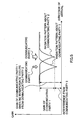
- FIG. 7A to FIG. 7C are view each showing an example of a radiation pattern formed by each ICU of the radio receiving apparatus according to Embodiment 2 of the present invention.
- FIGS. 7A to 7C it is assumed that the wider the width of the arrow becomes, the larger transmission power becomes.
- the ICU 606-1 performs the array reception using the null steering.
- the radiation pattern is generated in such a way that the null point is directed to the direction where the communication partner 2 exists. This makes it possible for the ICU 606-1 to generate the replica signal after eliminating interference received from the communication partner 2. As a result, the replica signal of the communication partner 1 can be accurately generated.
- the number of antennas is two, the number of null points that can be generated is only one, with the result that the null point is formed in the direction where the communication partner 2 providing a large quality of interference exists.
- the replica signal of the communication partner 1 is eliminated from the received signal by the adders 607-1 and 607-2 connected to the delayers 604-1 and 604-2, only the signals sent from the communication partners 2 and 3 are contained in the signals inputted to the ICU 606-2. Accordingly, in the ICU 606-2, as illustrated in FIG. 7B, the radiation pattern is generated in such a way that the null point is directed to the direction where the communication partner 3 exists. This makes it possible for the ICU 606-2 to generate the replica signal after eliminating interference received from the communication partner 3 from the signals from which interference received from the communication partner 1 is eliminated. As a result, the replica signal of the communication partner 2 can be accurately generated.
- the replica signals of the communication partners 1 and 2 are eliminated from the received signals by the adders 607-1 and 607-2 connected to the delayers 605-1 and 605-2, only the signal sent from the communication partner 3 is inputted to the ICU 606-3. Accordingly, in the ICU 606-3, as illustrated in FIG. 7C, the radiation pattern is generated in such a way that the beam point is directed to the direction where the communication partner 3 exists. This makes it possible to generate the replica signal of the communication partner 3 accurately.
- Embodiment 1 has explained the radio receiving apparatus in which the array antenna and the parallel type interference canceller are combined.
- the parallel type interference canceller is used, so that the inference signals of the respective communication partners are simultaneously eliminated in parallel in one stage. For this reason, in Embodiment 1, each ICU in one stage calculates the reception weights without considering the interference signals to be eliminated in the stage.
- the radio receiving apparatus of Embodiment 2 is the radio receiving apparatus in which the array antenna and the serial type interference canceller are combined as illustrated in FIG. 6.
- the interference signals are sequentially eliminated for every communication partner in one stage. Accordingly, in the radio receiving apparatus of this embodiment, the signals from which interference signals are sequentially eliminated are inputted to each ICU in one stage.
- each ICU of the radio receiving apparatus of this embodiment calculates the reception weights with respect to the signals from which the interference signals are sequentially eliminated in one stage.
- the radio receiving apparatus of this embodiment can generate the radiation pattern and the replica signal more accurately as compared with Embodiment 1. This makes it possible to obtain high interference cancellation capability even if the number of stages is further reduced as compared with Embodiment 1. Therefore, it is possible to further reduce the apparatus scale.
- the interference signals are sequentially eliminated every communication partner in one stage to update the reception weights sequentially every communication partner in one stage. This makes it possible to improve the accuracy of the radiation pattern and that of the replica signal. Therefore, according to the radio receiving apparatus and the radio receiving method according to this embodiment, it is possible to obtain high interference cancellation capability even if the number of stages is further reduced as compared with Embodiment 1, and this makes it possible to further reduce the apparatus scale.
- the method for estimating the direction of arrival is not particularly limited.
- the estimation of the direction of arrival aims to obtain the steering vector S k every antenna.
- the radio receiving apparatus of Embodiment 1 and 2 may obtain the steering vector S k using any method as long as the steering vector S k can be obtained.
- the radio receiving apparatus of Embodiment 1 and 2 calculate the correlation value between the signal received by each antenna and the known signal to make it possible to obtain the steering vector S k .
- Embodiment 1 has explained the radio receiving apparatus in which the array antenna and the parallel type interference canceller are combined.
- Embodiment 2 has explained the radio receiving apparatus in which the array antenna and the serial type interference canceller are combined.
- the present invention can be applied to the radio receiving apparatus in which the array antenna and the symbol ranking type interference canceller are combined.
- the present invention even if the array antenna and the interference canceller are combined, it is possible to receive a desired signal with high quality in an apparatus of small scale without providing an interference canceller to each channel corresponding to each communication partner.
- the present invention is suitable for use in a mobile station apparatus and a base station apparatus in a mobile communication system.
- it is possible to receive a desired signal with high quality in an apparatus of' small scale even if the array antenna and the interference canceller are combined in the mobile station apparatus and the base station apparatus.
Abstract
A reception weight calculation section 203
calculates reception weights W1 and W2 every antenna
using an optimal directional control method in order
to improve interference cancellation effect, an
arrival direction estimation section 204 estimates
a direction of arrive of a received signal for each
antenna to calculate steering vectors S1 and S2 for
each antenna, and a replica weight calculation
section 211 calculates replica weights Wr1 and Wr2
using the reception weights W1, W2 and steering
vectors S1, S2.
Description
- The present invention relates to a radio receiving apparatus and a radio receiving method used in a mobile communication system of CDMA (Code Division Multiple Access).
- In a mobile communication system of CDMA, since a plurality of user signals is transmitted in the same band, a signal that a radio receiving apparatus receives is subjected to interference by various signals to cause deterioration of characteristics.
- An array antenna is known as an apparatus for eliminating the interference. The array antenna is composed of a plurality of antenna elements, and is capable of setting reception directivity freely by providing adjustment of each of amplitude and phase to a signal received by each antenna element. In this case, adjustment of amplitude and phase provided to the received signal can be carried out by multiplying the received signal by weighting factor (hereinafter referred to as "reception weight"). The radio receiving apparatus can intensively receive only a signal coming from a desired direction by adjusting the reception weight by which the received signal is multiplied.
- Another apparatus for eliminating the interference, an interference canceller is known. The interference canceller is a technique for canceling a signal (interference) transmitted from other communication partners other than current communication partner from the received signal to extract a desired signal from the received signal. Conventionally, as an apparatus for canceling interference signals, there are apparatuses described in 1) "Sequential Channel Estimation Type Serial Canceller Using a pilot Symbol in DS-CDMA (Technical Bulletin, RCS95-50, July, 1995, Radio Communication System Research Society of the Institute of Electronics, Information and Communication Engineers)" authored by Sawahashi, Miki, Andoh, and Higuchi, 2) "Sequential Transmission Line Estimation Type CDMA Multistage Interference Canceller Utilizing a Symbol Replica Process (Technical Bulletin, RCS96-171, February, 1997, Radio Communication System Research Society of the Institute of Electronics, Information and Communication Engineers)" authored by Yoshida and Ushirokawa, and 3) "Study of CDMA Interference Canceller in an Upstream Line(Technical Bulletin, RCS96-121, January, 1997, Radio Communication System Research Society of the Institute of Electronics, Information and Communication Engineers)" written by Uesugi, Katoh, and Honma. The above three apparatuses are hereinafter referred to as 1) a serial type interference canceller, 2) a parallel type interference canceller, and 3) a symbol ranking type canceller.
- Here, it can be expected that the use of combination of the array antenna and the interference canceller provide a larger interference cancellation effect than each independent use.
- However, in the radio communication system that provides reception directivity to each channel corresponding to each communication partner by use of the array antenna, degree of interference with respect to each communication partner is different from one communication partner to another. Accordingly, in the case of applying the interference canceller to such the system, it is necessary to individually provide the interference canceller to each channel corresponding to each communication partner. Hence, the simple combination of the array antenna and the interference canceller increases the amount of calculations and the apparatus scale, making it difficult to implement such an apparatus in consideration given to actual hardware, design.
- It is an object of the present invention is to provide a radio receiving apparatus and a radio receiving method that are capable of receiving a desired signal with high quality in an apparatus of small scale without providing an interference canceller to each channel corresponding to each communication partner even when the array antenna and the interference canceller are combined.
- In order to attain the above object, the present invention generates a replica signal every signal received by each antenna of the array antenna to make it possible to receive a desired signal with high quality in an apparatus of small scale without providing an interference canceller to each channel corresponding to each communication partner even when the array antenna and the interference canceller are combined.
- Particularly, the present invention is characterized in that a reception weight by which an optimal radiation pattern is formed is calculated to improve an interference cancellation effect without limiting to a calculation algorithm of the reception weight. Moreover, the present invention is characterized in that the reception weight is sequentially updated using a signal from which a interference signal is sequentially eliminated to sequentially generate a radiation pattern with high reliability, whereby further improving the interference cancellation effect.
-
- FIG. 1 is a block diagram of a main part
illustrating a schematic configuration of a radio
receiving apparatus according to
Embodiment 1 of the present invention; - FIG. 2, is a block diagram of a main part
illustrating a schematic configuration of ICU of each
of first and second stages of an interference signal
canceling apparatus according to
Embodiment 1 of the present invention; - FIG. 3 is a block diagram of a main part
illustrating a schematic configuration of ICU of a
third stage of the interference signal canceling
apparatus according to
Embodiment 1 of the present invention; - FIG. 4 is a view of a radiation pattern formed by a beam steering.
- FIG. 5 is a view of a radiation pattern formed by a null steering.
- FIG. 6 is a block diagram of a main part
illustrating a schematic configuration of a radio
receiving apparatus according to
Embodiment 2 of the present invention; - FIG. 7A is a view showing one example of a
radiation pattern formed by each ICU of the radio
receiving apparatus according to
Embodiment 2 of the present invention; - FIG. 7B is a view showing one example of a
radiation pattern formed by each ICU of the radio
receiving apparatus according to
Embodiment 2 of the present invention; and - FIG. 7C is a view showing one example of a
radiation pattern formed by each ICU of the radio
receiving apparatus according to
Embodiment 2 of the present invention. -
- Embodiments of the present invention will be specifically described with reference to the drawings accompanying herewith.
- FIG. 1 is a block diagram of a main part illustrating a schematic configuration of a radio receiving apparatus according to
Embodiment 1 of the present invention. The following will explain the case in which the number of stages of the interference canceller is 3, the number of communication partners is 3, and the number of multipaths is 3. It is noted that these numbers are just one example, and this Embodiment is not limited to these number. - In addition, as illustrated in FIG. 1, since the first stage and the second stage have the same configuration, the same reference numerals are added to the same structural parts, and the explanation of the second stage is omitted.
- In FIG. 1, a signal received via an antenna 101-1 is inputted to ICUs (Interference Canceling Units) 102-1 to 102-3 and a delayer 103-1 provided to correspond to the antenna 101-1. Similarly, a signal received via an antenna 101-2 is inputted to ICUs 102-1 to 102-3 and a delayer 103-2 provided to correspond to the antenna 101-2.
- ICUs 102-1 to 102-3 are provided to correspond to
communication partners 1 to 3, respectively, and each generates a replica signal in connection with each of the signals received via the antennas 101-1 and 101-2. The replica signals generated by the ICUs 102-1 to 102-3 are inputted to adders 104-1 and 104-2 provided to correspond to the antennas 101-1 and 101-2, and are inputted to adders 105-1 and 105-2. The configuration of each of the ICUs 102-1 to 102-3 will be described later. - The delayers 103-1 and 103-2 delay the received signals by processing time of ICUs 102-1 to 102-3, and each outputs the resultant to each of the adders 104-1 and 104-2.
- In the adder 104-1, the replica signals of
communication partners 1 to 3 for the signal received via the antenna 101-1 are subtracted from the signal received via the antenna 101-1. Also, in the adder 104-2, the replica signals ofcommunication partners 1 to 3 for the signal received via the antenna 101-2 are subtracted from the signal received via the antenna 101-2. This eliminates the replica signals of all communication partners from the signals received via the respective antennas. Signals (residual signals) obtained by eliminating the replica signals of all communication partners from the received signals are inputted to the adders 105-1 and 105-2, respectively, and are inputted to the delayers 103-1 and 103-2 of the second stage. - In the adders 105-1 and 105-2, the replica signals for the signals received via the antennas 101-1 and 101-2 and the residual signals are added every communication partner. This eliminates the replica signal of
communication partner 1, the replica signal ofcommunication partner 2, the replica signal ofcommunication partner 3 from the received signals every antenna. Namely, when attention is paid tocommunication partner 1, the signal fromcommunication partner 2 and the signal fromcommunication partner 3, which cause interference withcommunication partner 1, are eliminated from the received signal to obtain a desired signal forcommunication partner 1 every antenna. The similar processing is carried out, so that the signals of other communication partners causing interference are eliminated from the received signals, so that the desired signal forcommunication partner 2 and the desired signal forcommunication partner 3 can be obtained every antenna. The obtained desired signals are inputted to ICUs 102-1 to 102-3 of the second stage, respectively. - According to the radio receiving apparatus of this embodiment, the same processing as performed in the first stage is repeated in the second stage, so that the accuracy of replica signal is improved and that of the interference signal cancellation is improved. In other words, the more the number of stages are increased, the more the inference signals sent from the other communication partners that cause interference with the respective communication partners are eliminated.
- The signals added by the adders 105-1 and 105-2 of the second stage are inputted to ICUs 106-1 to 106-3 of the third stage, and are demodulated. This obtains
demodulated signals 1 to 3 of thecommunication partners 1 to 3. The configuration of each of the ICUs 106-1 to 106-3 will be described later. - An explanation will be next given of ICUs 102-1 to 102-3 and ICUs 106-1 to 106-3. FIG. 2 is a block diagram of a main part illustrating a schematic configuration of ICU of each of first and second stages of an interference signal canceling apparatus according to
Embodiment 1 of the present invention. Also, FIG. 3 is a block diagram of a main part illustrating a schematic configuration of ICU of a third stage of the interference signal canceling apparatus according toEmbodiment 1 of the present invention. Additionally, ICUs 102-1 to 102-3 of the first and second stages have the same configuration and operation, respectively. Also, ICUs 106-1 to 106-3 of the third stage have the same configuration and operation. Accordingly, in the explanation set forth below, the ICU 102-1 of the first stage and the ICU 106-1 of the third stage corresponding to thecommunication partner 1 are explained, and the explanation of the respective ICUs corresponding to thecommunication partner 2 and thecommunication partner 3 is omitted. Moreover, the ICU 102-1 shown in FIG. 2 and the ICU 106-1 shown in FIG. 3 are configured on the assumption that the number of multipath to the radio receiving apparatus is 3. In FIGS. 2 and 3, the respective configuration parts for the respective paths are shown by P1 to P3, respectively. Since the respective configuration parts for the respective paths have the same configuration and operation, only the first path P1 is illustrated, and the explanation of the second path P2 and third path P3 is omitted. - In FIG. 2, the ICU 102-1 briefly includes a preceding stage S1 in which the signals received by the respective antennas 101-1 and 101-2 are subjected to despreading and then the resultants are multiplied by reception weights of the receptive antennas, respectively, an intermediate stage S2 in which RAKE combining and provisional decision are carried out, and the last stage S3 in which the signal subjected to provisional decision is multiplied by a weighting factor for generating a replica signal (hereinafter referred to as "replica weight") to generate a replica signal.
- The signal received via the antenna 101-1 is despread by a despreading section 201-1 and the signal received via the antenna 101-2 is despread by a despreading section 201-2. Despread signals X1 and X2 are inputted to multipliers 202-1, 202-2, a reception
weight calculation section 203, and an arrivaldirection estimation section 204. - The reception
weight calculation section 203 calculates weights W1 and W2 of each antenna, and outputs the resultants to multipliers 202-1 and 202-2, and a replicaweight calculation section 211. Since the receptionweight calculation section 203 is provided every path and every communication partner, making it possible to calculate the reception weights each being different every path and every user. The calculation method for the reception weight will be described later. - The arrival
direction estimation section 204 estimates a direction of arrival of the received signal every antenna, and outputs steering vectors S1 and S2 of the respective antennas to the replicaweight calculation section 211, and the arrivaldirection estimation section 204 of the second stage. Here, the reason why the arrivaldirection estimation section 204 of the first stage outputs the steering vectors S1 and S2 to the arrivaldirection estimation section 204 of the second stage is as follows. Specifically, the arrivaldirection estimation section 204 of the second stage averages the steering victors calculated in the first stage and the steering victors calculated in the second stage every path, and uses the resultant as a steering vector in the second stage. This makes it possible to increase the accuracy of the steering vector as the operation goes to the last stage. In other words, the accuracy of the direction of arrival can be improved as the operation goes to the last stage, making it possible to improve the accuracy of the calculation of the replica weight. - Here, since the signal inputted to each stage is a signal from which an interference signal is eliminated in the previous stage, the signal whose interference state changes every stage is inputted. Hence, according to this embodiment, the reception
weight calculation section 203 and the arrivaldirection estimation section 204 are provided on a stage-by-stage basis. This makes it possible to adaptively change the radiation pattern in accordance with the state of the inference signal at this point on the stage-by-stage basis. Hence, according to this embodiment, the radiation pattern and the replica signal can be accurately generated. This eliminates the useless processing wherein interference cancellation using directional control is further performed to interference that can be sufficiently cancelled by only interference cancellation processing, conversely; interference cancellation processing is further performed to interference that can be sufficiently cancelled by only directional control. - Moreover, according to this embodiment, the direction of arrival of the signal from which the interference signals are sequentially cancelled is estimated. Hence, the accuracy of estimation of the direction of arrival is improved as the operation goes to the last stage. Accordingly, since the interference cancellation having good performance can be carried out with a relatively small number of stages, the apparatus scale can be reduced.
- Despread signals X1 and X2 are multiplied by reception weights W1 and W2 by the multipliers 202-1 and 202-2, respectively, and the resultant is added by an
adder 205. This carries out array combining. The signal subjected to array combining is outputted to achannel estimation section 206 and is outputted to amultiplier 207. - The
channel estimation section 206 performs the channel estimation based on the signal subjected to the array combining, and outputs the resultant to a complex conjugate ha* of a channel estimation value ha to themultiplier 207, and outputs the channel estimation value ha to amultiplier 210. Themultiplier 207 multiplies the signal subjected to the array combining by the complex conjugate ha* of the channel estimation value. This compensates for phase rotation of the signal subjected to the array combining. - The signal, which has been subjected to the array combining of each of paths P1 to P3 and which has been multiplied by the complex conjugate ha* of the channel estimation value, is subjected to RAKE combining by an
adder 208 of the intermediate stage S2. The result obtained by RAKE combining is temporarily decided by adecider 209. A signal d subjected to temporarily decision is multiplied by the channel estimation value ha by amultiplier 210 for each of paths P1 to P3, and the resultant is inputted to multipliers 212-1 and 212-2, respectively. - A replica
weight calculation section 211 calculates replica weights Wr1 and Wr2 using reception weights W1 and W2 and steering vectors S1 and S2, and outputs the resultant to the multipliers 212-1 and 212-2, respectively. The method for calculating the replica weight will be described later. - The multipliers 212-1 and 212-2 multiply the signals outputted from the
multiplier 210 by replica weights Wr1 and Wr2, respectively. This obtains replica signals Xr1 and Xr2 corresponding to X1 and X2, respectively. The replica signals Xr1 and Xr2 are spread by re-spreading sections 213-1 and 213-2, respectively, and the resultants are inputted to adders 214-1 and 214-2. The replica signals Xr1 and Xr2 re-spread for each of paths P1 to P3 are added by adders 214-1 and 214-2, respectively, and the resultants are inputted to adders 105-1 and 105-2. - Next, the ICU 106-1 of the third stage will be described. As illustrated in FIG. 3, the ICU 106-1 of the third stage has substantially the same structure as that of the preceding stage S1 and that of the intermediate stage S2 of the ICU 102-1 of FIG. 2. Accordingly, the same reference numerals are added to the same configuration parts as those of the ICU102-1 of FIG. 2, and the explanation of the ICU 106-1 of the third stage will be omitted. The ICU 106-1 is different from the ICU 102-1 in the point that there is no the arrival
direction estimation section 204 provided in the ICU 102-1. This is because in the third stage, demodulatedsignal 1 is outputted instead of the replica signal, and therefore the replica weight necessary for generating the replica signals not required, whereby steering vector necessary for calculating the replica weight is not required also. - An explanation will be next given of the method for calculating the reception weights W1 and W2, and the method for calculating the replica weights Wr1 and Wr2.
- The method of directional control using the array antenna is largely divided into directional control carried out by a beam steering and directional control carried out by a null steering.
- The beam steering is a method in which interference from the other communication partners is eliminated by generating such a radiation pattern that directs directivity to a direction where a desired communication partner exists. On the other hand, the null steering is a method in which interference from the other communication partners is eliminated by generating a radiation pattern that forms a null point in a direction where a desired communication partner exists.
- In the case of performing array reception using the beam steering, the signals received by the respective antennas are multiplied by in-phase addition weights as reception weights W1 and W2 such that the signals received by the respective antennas are added in a state that they all are in phase with each other. Here, the in-phase addition weights are weights that adjust only phases of the signals received by the respective antenna. For this reason, in the case of using the in-phase addition weights as reception weights W1 and W2, the signals subjected to provisional decision are multiplied by complex conjugates of reception weights W1 and W2 as replica weights Wr1 and Wr2 in order to return the adjusted phases to the original. This makes it possible to generate replica signals Xr1 and Xr2 for each antenna.
- However, in the case of the beam steering (namely, in-phase addition weight), the radiation pattern is not in a pointed form as illustrated in FIG. 4. Moreover, in the case of the beam steering, control is performed in such a way that the center of the radiation pattern is directed to the direction where a desired communication partner exists. For this reason, when the direction where the desired communication partner exists and the direction where the communication partner, which causes interference, exists are close to each other or when transmission power of the communication partner, which causes interference, is greater than that of the desired communication partner, it is impossible to sufficiently eliminate interference with respect to the desired communication partner.
- Morespecifically, as illustrated in FIG. 4, when
communication partner 2 exists closely in the direction where a desiredcommunication partner 1 exists, the signal sent from thecommunication partner 2 that causes interference with thecommunication partner 1 cannot be fully eliminated in the case of the beam steering. For this reason, the gain of the desiredcommunication partner 1 becomes extremely small as compared with the case in which there is no interference from thecommunication partner 2. - On the other hand, in the case of the null steering, such a radiation pattern that directs the null point to the direction, where the
communication partner 2 that causes interference exists, is formed in connection with the desiredcommunication partner 1 as illustrated in FIG. 5. This makes it possible to fully eliminate the signal sent from thecommunication partner 2 that causes interference with thecommunication partner 1. As a result, the gain of the desiredcommunication partner 1 becomes extremely large as compared with the case of using the beam steering. In this way, it is useful to perform the array reception using the null steering at the time of eliminating the interference signal. - Accordingly, the radio receiving apparatus of this embodiment performs the array reception using the null steering. In other words, the reception
weight calculation section 203 shown in FIG. 2 calculates reception weights W1 and W2 by a control algorithm using, for example, MMSE (Minimum Means Square Error) as a code so as to obtain the null point. - However, reception weights W1 and W2 thus obtained are not the weights that adjust only the phases of the signals received by the respective antennas. Hence, in the case of performing the array reception using the null steering, replica signals Xr1 and Xr2 for every antenna cannot be generated by multiplying the signals subjected to provisional decision by complex conjugates of reception weights W1 and W2 as replica weights Wr1 and Wr2.
- For this reason, according to this embodiment, the replica
weight calculation section 211 shown in FIG. 2 calculates a replica weight Wrk in the following way. Additionally, in this embodiment, since the number of array antennas is two, k is 1 or 2. - It is assumed that a signal subjected to provisional decision by the
decider 209 is d, a steering vector of each antenna obtained by the arrivaldirection estimation section 204 is Sk and a channel estimation value of a signal Xk received by each antenna is h. The replica signal Xrk can be expressed by the following equation (1): - Additionally, since it is assumed that fading correlation between the array antennas is 1, the channel estimation values of the signals received by the respective antennas are all h.
- Moreover, it is assumed that the channel estimation value of the signal subjected to array combining obtained by the
channel estimation section 206 is ha and a reception weight by which the signal Xk received by each antenna is multiplied is Wk. The following equation is established.where n denotes the number of antenna.
- Substitution of equation (1) into equation (2) yields the following equation (3):

- From the equation (3), the following equation (4) is established:

- Next, substitution of equation (4) into equation (1) yields the following equation (5):

- Moreover, the replica signal Xrk can be expressed by the following equation (6):
- Then, comparison between equation (5) and (6) is performed and the following equation (7) can be obtained as a replica weight Wrk by the replica
weight calculation section 211.
- Accordingly, the radio receiving apparatus of this embodiment can calculate the replica weight Wrk without limitation of the kinds of the reception weights even if any kind of reception weight is used as a reception weight Wk.
- Therefore, the radio receiving apparatus of this embodiment can generate the replica signal Xrk every antenna even if the replica weight Wrk is not the complex conjugate of the reception weight Wk. In other words, since the kind of reception weight used in the radio receiving apparatus of this embodiment is not limited to the in-phase addition weight, the radio receiving apparatus of this embodiment can perform the array reception using the null steering having high interference cancellation effect.
- The above has explained the case in which the array reception is performed using the null steering as one example. The radio receiving apparatus of this embodiment can generate the replica signal even if any kind of reception weight is used, so that the method of the array reception is not limited to the null steering.
- For example, in the case where the radio receiving apparatus of this embodiment performs the array reception using the beam steering, the arrival
direction estimation section 204 outputs the steering vector Sk to the receptionweight calculation section 203, and the receptionweight calculation section 203 calculates the reception weight Wk as a complex conjugate Sk* of the steering vector Sk. - Namely, Wk in the above equation (7) is equal to Sk*.
- Accordingly, the replica
weight calculation section 211 calculates the replica weight Wrk using the above equation (7) to obtain the following equation (9): - Accordingly, since the replica weight Wrk serves as a complex conjugate of the reception weight Wk, the radio receiving apparatus of this embodiment can use the in-phase addition weight also as a reception weight Wk.
- In this way, according to the radio receiving apparatus and the radio receiving method of this embodiment, the array reception is performed using the optimal directional control method in order to improve the interference cancellation effect without limiting to a calculation algorithm of the reception weight, and the replica signal can be generated every signal received by each antenna of the array antenna. This makes it possible to receive a desired signal with high quality in an apparatus of small scale even when the array antenna and the interference canceller are combined.
- Moreover, according to the radio receiving apparatus and the radio receiving method of this embodiment, the reception weight can be updated in accordance with the change in the state of interference. This makes it possible to generate the radiation pattern and the replica signal accurately.
Accordingly, according to the radio receiving apparatus and the radio receiving method of this embodiment,' since the interference cancellation having good performance can be carried out with a relatively small number of stages, the apparatus scale can be reduced. - Still' moreover, according to the radio receiving apparatus and the radio receiving method of this embodiment, since, the accuracy of the estimation of the direction of arrival can be improved as the operation goes to the last stage, the accuracy of the calculation of the replica weight can be improved.
- The radio receiving apparatus and the radio receiving method of this embodiment are to eliminate the interference signals sequentially every communication partner in one stage and to update the reception weights sequentially every communication partner in one stage.
- FIG. 6 is a block diagram of a main part illustrating a schematic configuration of a radio receiving apparatus according to
Embodiment 2 of the present invention. Additionally, ICUs 606-1 to 606-3 shown in FIG. 6 have the same configuration as that of the ICU 102-1 shown in FIG. 2, and the detailed explanation of each ICU is omitted. It is noted that the ICU 606-1 and 606-2 of the third stage shown in FIG. 6 adopt the configuration that output the replica signal and output demodulatedsignal - In addition, as illustrated in FIG. 6, since the first to third stages have the same configuration, the same reference numerals are added to the same structural parts, and the explanation of the second and third stages are omitted.
- Signals received via antennas 601-1 and 601-2 are inputted to delayers 602-1,602-2, and 603-1, 603-2, respectively. The received signals inputted to the delayers 602-1,602-2 are delayed by a given time and outputted to the second stage. The received signals inputted to the delayers 603-1,603-2 are delayed by a given time, and outputted to the ICU 606-1 and outputted to delayers 604-1 and 604-2.
- In the ICU 606-1, a reception weight, a steering vector, and a replica signal of the
communication partner 1 are generated every antenna based on the received signal. The replica signal of thecommunication partner 1 generated every antenna is inputted to each of adders 607-1 and 607-2, and the steering vector every antenna is inputted to the ICU 606-1 of the second stage. - In the adders 607-1 and 607-2 connected to the delayers 604-1, 604-2, the replica signals of the
communication partner 1 are eliminated from the received signals delayed by the delayers 604-1, and' 604-2. - In the ICU 606-2, a reception weight, a steering vector, and a replica signal of the
communication partner 2 are generated every antenna based on a signal obtained by eliminating the replica signal of thecommunication partner 1, from the received signal. The replica signal of thecommunication partner 2 generated every antenna is inputted to each of next adders 607-1 and 607-2, and the steering vector every antenna is inputted to the ICU 606-2 of the second stage. - In the adders 607-1 and 607-2 connected to the delayers 605-1, 605-2, the replica signals of the
communication partner 1 and those of thecommunication partner 2 are eliminated from the received signals delayed by the delayers 605-1, and 605-2. - Then, in the ICU 606-3, a reception weight, a steering vector, and a replica signal of the
communication partner 3 are generated every antenna based on a signal obtained by eliminating the replica signal of thecommunication partner 1 and the replica signal of thecommunication partner 2 from the received signal. - In this way, since each ICU in one stage calculates the reception weight based on the signal from which the interference signals are sequentially eliminated, the reception weights are sequentially updated every communication partner in one stage.
- An explanation will be next given of the radiation pattern generated by each ICU of the first stage using FIGS. 7A to 7C. FIG. 7A to FIG. 7C are view each showing an example of a radiation pattern formed by each ICU of the radio receiving apparatus according to
Embodiment 2 of the present invention. In FIGS. 7A to 7C, it is assumed that the wider the width of the arrow becomes, the larger transmission power becomes. - First, all signals sent from the
communication partners 1 to 3 are contained in the signals inputted in the ICU 606-1. It is assumed that the ICU 606-1 performs the array reception using the null steering. In the ICU 606-1, as shown in FIG. 7A, the radiation pattern is generated in such a way that the null point is directed to the direction where thecommunication partner 2 exists. This makes it possible for the ICU 606-1 to generate the replica signal after eliminating interference received from thecommunication partner 2. As a result, the replica signal of thecommunication partner 1 can be accurately generated. - The reason why the null point is not directed to the direction where the
communication partner 3 exists is as follows: - Since the number of antennas is two, the number of null points that can be generated is only one, with the result that the null point is formed in the direction where the
communication partner 2 providing a large quality of interference exists. - Since the replica signal of the
communication partner 1 is eliminated from the received signal by the adders 607-1 and 607-2 connected to the delayers 604-1 and 604-2, only the signals sent from thecommunication partners communication partner 3 exists. This makes it possible for the ICU 606-2 to generate the replica signal after eliminating interference received from thecommunication partner 3 from the signals from which interference received from thecommunication partner 1 is eliminated. As a result, the replica signal of thecommunication partner 2 can be accurately generated. - Then, since the replica signals of the
communication partners communication partner 3 is inputted to the ICU 606-3. Accordingly, in the ICU 606-3, as illustrated in FIG. 7C, the radiation pattern is generated in such a way that the beam point is directed to the direction where thecommunication partner 3 exists. This makes it possible to generate the replica signal of thecommunication partner 3 accurately. -
Embodiment 1 has explained the radio receiving apparatus in which the array antenna and the parallel type interference canceller are combined. In the radio receiving apparatus ofembodiment 1, the parallel type interference canceller is used, so that the inference signals of the respective communication partners are simultaneously eliminated in parallel in one stage. For this reason, inEmbodiment 1, each ICU in one stage calculates the reception weights without considering the interference signals to be eliminated in the stage. - In contrast to this, the radio receiving apparatus of
Embodiment 2 is the radio receiving apparatus in which the array antenna and the serial type interference canceller are combined as illustrated in FIG. 6. For this reason, in the radio receiving apparatus of this embodiment, the interference signals are sequentially eliminated for every communication partner in one stage. Accordingly, in the radio receiving apparatus of this embodiment, the signals from which interference signals are sequentially eliminated are inputted to each ICU in one stage. - In other words, each ICU of the radio receiving apparatus of this embodiment calculates the reception weights with respect to the signals from which the interference signals are sequentially eliminated in one stage. Hence, as compared with each ICU of the radio receiving apparatus of
Embodiment 1, it is possible to calculate the reception weights with respect to the signals having a small amount of interference. Accordingly, the radio receiving apparatus of this embodiment can generate the radiation pattern and the replica signal more accurately as compared withEmbodiment 1. This makes it possible to obtain high interference cancellation capability even if the number of stages is further reduced as compared withEmbodiment 1. Therefore, it is possible to further reduce the apparatus scale. - Thus, according to the radio receiving apparatus and the radio receiving method according to this embodiment, the interference signals are sequentially eliminated every communication partner in one stage to update the reception weights sequentially every communication partner in one stage. This makes it possible to improve the accuracy of the radiation pattern and that of the replica signal. Therefore, according to the radio receiving apparatus and the radio receiving method according to this embodiment, it is possible to obtain high interference cancellation capability even if the number of stages is further reduced as compared with
Embodiment 1, and this makes it possible to further reduce the apparatus scale. - Additionally, in
Embodiments Embodiment Embodiment -
Embodiment 1 has explained the radio receiving apparatus in which the array antenna and the parallel type interference canceller are combined.Embodiment 2 has explained the radio receiving apparatus in which the array antenna and the serial type interference canceller are combined. However, the present invention can be applied to the radio receiving apparatus in which the array antenna and the symbol ranking type interference canceller are combined. - As explained above, according to the present invention, even if the array antenna and the interference canceller are combined, it is possible to receive a desired signal with high quality in an apparatus of small scale without providing an interference canceller to each channel corresponding to each communication partner.
- This application is based on the Japanese Patent Application No. 2000-010878 filed on January 19, 2000, entire content of which is expressly incorporated by reference herein
- The present invention is suitable for use in a mobile station apparatus and a base station apparatus in a mobile communication system. In the case of application, it is possible to receive a desired signal with high quality in an apparatus of' small scale even if the array antenna and the interference canceller are combined in the mobile station apparatus and the base station apparatus.
Claims (9)
- A radio receiving apparatus comprising:a first calculation section for calculating reception weighting factors with respect to received signals received by the respective antenna element composing an adaptive array antenna;an arrival direction estimation section for estimating directions of arrival of said received signals;a second calculation section for calculating weighting factors for a replica signal generation in accordance with said reception weighting factors and said directions of arrival;a replica signal generator for generating replica signals of each of said received signals using said weighting factors for a replica signal generation; andan eliminator for eliminating said replica signals from said received signals.
- The radio receiving apparatus according to claim 1, whereinsaid first calculation section calculates reception weighting factors by which a radiation pattern is formed in such a way that a null point is directed to a direction where an interference signal source exists.
- The radio receiving apparatus according to claim 1, comprisinga plurality of processors each having said first calculation section, said arrival direction estimation section, and said eliminator, as a multistage.
- The radio receiving apparatus according to claim 3, whereinin the processor of a latter stage,said first calculation section calculates the reception weighting factors with respect to the signals obtained by eliminating the replica signals from the received signals by said eliminator in a preceding stage, whereby updating the reception weighting factors sequentially.
- The radio receiving apparatus according to claim 3, whereinin the processor of a latter stage,said arrival direction estimation section estimates the directions of arrival of the signals obtained by eliminating the replica signals from the received signals by said eliminator in a preceding stage.
- The radio receiving apparatus according to claim 5, whereinin the processor of a latter stage,said arrival direction estimation section estimates the directions of arrival using an average value of calculated steering vectors in a given interval.
- A mobile station apparatus having a radio receiving apparatus thereon, said radio receiving apparatus comprising:a first calculation section for calculating reception weighting factors with respect to received signals received by the respective antenna element composing an adaptive array antenna;an arrival direction estimation section for estimating directions of arrival of said received signals;a second calculation section for calculating weighting factors for a replica signal generation in accordance with said reception weighting factors and said directions of arrival;a replica signal generator for generating replica signals of each of said received signals using said weighting factors for a replica signal generation; andan eliminator for eliminating said replica signals from said received signals.
- A base station apparatus having a radio receiving apparatus thereon, said radio receiving apparatus comprising:a first calculation section for calculating reception weighting factors with respect to received signals received by the respective antenna element composing an adaptive array antenna;an arrival direction estimation section for estimating directions of arrival of said received signals;a second calculation section for calculating weighting factors for a replica signal generation in accordance with said reception weighting factors and said directions of arrival;a replica signal generator for generating replica signals of each of said received signals using said weighting factors for a replica signal generation; andan eliminator for eliminating said replica signals from said received signals.
- A radio receiving method comprising the steps of:calculating reception weighting factors with respect to received signals received by the respective antenna element composing an adaptive array antenna;estimating directions of arrival of said received signals;calculating weighting factors for a replica signal generation in accordance with said reception weighting factors and said directions of arrival;generating replica signals of each of said received signals using said weighting factors for a replica signal generation; andeliminating said replica signals from said received signals.
Applications Claiming Priority (3)
| Application Number | Priority Date | Filing Date | Title |
|---|---|---|---|
| JP2000010878A JP3619729B2 (en) | 2000-01-19 | 2000-01-19 | Radio receiving apparatus and radio receiving method |
| JP2000010878 | 2000-01-19 | ||
| PCT/JP2001/000250 WO2001054310A1 (en) | 2000-01-19 | 2001-01-17 | Radio receiving device and radio receiving method |
Publications (1)
| Publication Number | Publication Date |
|---|---|
| EP1170879A1 true EP1170879A1 (en) | 2002-01-09 |
Family
ID=18538834
Family Applications (1)
| Application Number | Title | Priority Date | Filing Date |
|---|---|---|---|
| EP20010901376 Withdrawn EP1170879A1 (en) | 2000-01-19 | 2001-01-17 | Radio receiving device and radio receiving method |
Country Status (6)
| Country | Link |
|---|---|
| US (1) | US7047044B2 (en) |
| EP (1) | EP1170879A1 (en) |
| JP (1) | JP3619729B2 (en) |
| CN (1) | CN1147066C (en) |
| AU (1) | AU2704201A (en) |
| WO (1) | WO2001054310A1 (en) |
Cited By (15)
| Publication number | Priority date | Publication date | Assignee | Title |
|---|---|---|---|---|
| WO2004039011A2 (en) * | 2002-10-25 | 2004-05-06 | Qualcomm Incorporated | Mimo wlan system |
| US7986742B2 (en) | 2002-10-25 | 2011-07-26 | Qualcomm Incorporated | Pilots for MIMO communication system |
| US8134976B2 (en) | 2002-10-25 | 2012-03-13 | Qualcomm Incorporated | Channel calibration for a time division duplexed communication system |
| US8145179B2 (en) | 2002-10-25 | 2012-03-27 | Qualcomm Incorporated | Data detection and demodulation for wireless communication systems |
| US8169944B2 (en) | 2002-10-25 | 2012-05-01 | Qualcomm Incorporated | Random access for wireless multiple-access communication systems |
| US8194770B2 (en) | 2002-08-27 | 2012-06-05 | Qualcomm Incorporated | Coded MIMO systems with selective channel inversion applied per eigenmode |
| US8203978B2 (en) | 2002-10-25 | 2012-06-19 | Qualcomm Incorporated | Multi-mode terminal in a wireless MIMO system |
| US8208364B2 (en) | 2002-10-25 | 2012-06-26 | Qualcomm Incorporated | MIMO system with multiple spatial multiplexing modes |
| US8218609B2 (en) | 2002-10-25 | 2012-07-10 | Qualcomm Incorporated | Closed-loop rate control for a multi-channel communication system |
| US8358714B2 (en) | 2005-06-16 | 2013-01-22 | Qualcomm Incorporated | Coding and modulation for multiple data streams in a communication system |
| US8570988B2 (en) | 2002-10-25 | 2013-10-29 | Qualcomm Incorporated | Channel calibration for a time division duplexed communication system |
| US8855226B2 (en) | 2005-05-12 | 2014-10-07 | Qualcomm Incorporated | Rate selection with margin sharing |
| US8873365B2 (en) | 2002-10-25 | 2014-10-28 | Qualcomm Incorporated | Transmit diversity processing for a multi-antenna communication system |
| US9154274B2 (en) | 2002-10-25 | 2015-10-06 | Qualcomm Incorporated | OFDM communication system with multiple OFDM symbol sizes |
| US9473269B2 (en) | 2003-12-01 | 2016-10-18 | Qualcomm Incorporated | Method and apparatus for providing an efficient control channel structure in a wireless communication system |
Families Citing this family (8)
| Publication number | Priority date | Publication date | Assignee | Title |
|---|---|---|---|---|
| CN100459535C (en) * | 2002-10-25 | 2009-02-04 | 高通股份有限公司 | MIMO WLAN system |
| US7386057B2 (en) * | 2003-02-20 | 2008-06-10 | Nec Corporation | Iterative soft interference cancellation and filtering for spectrally efficient high-speed transmission in MIMO systems |
| JP2006013786A (en) * | 2004-06-24 | 2006-01-12 | Ntt Docomo Inc | Adaptive antenna array receiver and its method |
| US8509287B2 (en) * | 2009-10-23 | 2013-08-13 | Broadcom Corporation | Method and system for diversity processing utilizing a programmable interface suppression module |
| JP5337111B2 (en) * | 2010-01-07 | 2013-11-06 | 株式会社エヌ・ティ・ティ・ドコモ | Signal detection apparatus and signal detection method used in a radio station of a radio communication system |
| KR101889677B1 (en) | 2015-06-12 | 2018-08-17 | 제이에프이미네라르 가부시키가이샤 | Therapeutic agent for skin wound or rough skin |
| US10330770B2 (en) * | 2017-11-09 | 2019-06-25 | Cisco Technology, Inc. | Channel estimation in OFDMA for switched antenna array based angle-of-arrival location |
| WO2023053193A1 (en) * | 2021-09-28 | 2023-04-06 | 三菱電機株式会社 | Wireless communication device, control circuit, storage medium, and signal processing method |
Family Cites Families (8)
| Publication number | Priority date | Publication date | Assignee | Title |
|---|---|---|---|---|
| JPH10190495A (en) | 1996-12-20 | 1998-07-21 | Fujitsu Ltd | Interference canceler |
| JP2991179B2 (en) * | 1998-01-08 | 1999-12-20 | 日本電気株式会社 | CDMA multi-user receiver |
| JP3335900B2 (en) * | 1998-02-27 | 2002-10-21 | 松下電器産業株式会社 | Interference removal apparatus and interference removal method |
| JPH11251959A (en) * | 1998-03-05 | 1999-09-17 | Fujitsu Ltd | Interference canceler device and radio communication equipment |
| JP3406831B2 (en) * | 1998-03-19 | 2003-05-19 | 富士通株式会社 | Array antenna system for wireless base station |
| US6385185B1 (en) * | 1998-06-25 | 2002-05-07 | Lucent Technologies Inc. | Methods and apparatus for coherent detection of signals with orthogonal data modulation |
| JP2000138605A (en) | 1998-10-30 | 2000-05-16 | Nec Corp | Multi-user receiver |
| JP2001016148A (en) | 1999-06-28 | 2001-01-19 | Fujitsu Ltd | Interference canceler system using array antenna and interference replica generation unit |
-
2000
- 2000-01-19 JP JP2000010878A patent/JP3619729B2/en not_active Expired - Fee Related
-
2001
- 2001-01-17 WO PCT/JP2001/000250 patent/WO2001054310A1/en not_active Application Discontinuation
- 2001-01-17 AU AU27042/01A patent/AU2704201A/en not_active Abandoned
- 2001-01-17 EP EP20010901376 patent/EP1170879A1/en not_active Withdrawn
- 2001-01-17 CN CNB018000371A patent/CN1147066C/en not_active Expired - Fee Related
- 2001-01-17 US US09/936,728 patent/US7047044B2/en not_active Expired - Fee Related
Non-Patent Citations (1)
| Title |
|---|
| See references of WO0154310A1 * |
Cited By (34)
| Publication number | Priority date | Publication date | Assignee | Title |
|---|---|---|---|---|
| US8194770B2 (en) | 2002-08-27 | 2012-06-05 | Qualcomm Incorporated | Coded MIMO systems with selective channel inversion applied per eigenmode |
| US8570988B2 (en) | 2002-10-25 | 2013-10-29 | Qualcomm Incorporated | Channel calibration for a time division duplexed communication system |
| US8203978B2 (en) | 2002-10-25 | 2012-06-19 | Qualcomm Incorporated | Multi-mode terminal in a wireless MIMO system |
| US8134976B2 (en) | 2002-10-25 | 2012-03-13 | Qualcomm Incorporated | Channel calibration for a time division duplexed communication system |
| US8711763B2 (en) | 2002-10-25 | 2014-04-29 | Qualcomm Incorporated | Random access for wireless multiple-access communication systems |
| US8170513B2 (en) | 2002-10-25 | 2012-05-01 | Qualcomm Incorporated | Data detection and demodulation for wireless communication systems |
| US8169944B2 (en) | 2002-10-25 | 2012-05-01 | Qualcomm Incorporated | Random access for wireless multiple-access communication systems |
| WO2004039011A3 (en) * | 2002-10-25 | 2005-07-14 | Qualcomm Inc | Mimo wlan system |
| US8750151B2 (en) | 2002-10-25 | 2014-06-10 | Qualcomm Incorporated | Channel calibration for a time division duplexed communication system |
| US8208364B2 (en) | 2002-10-25 | 2012-06-26 | Qualcomm Incorporated | MIMO system with multiple spatial multiplexing modes |
| US8218609B2 (en) | 2002-10-25 | 2012-07-10 | Qualcomm Incorporated | Closed-loop rate control for a multi-channel communication system |
| US8320301B2 (en) | 2002-10-25 | 2012-11-27 | Qualcomm Incorporated | MIMO WLAN system |
| US8355313B2 (en) | 2002-10-25 | 2013-01-15 | Qualcomm Incorporated | MIMO system with multiple spatial multiplexing modes |
| US10382106B2 (en) | 2002-10-25 | 2019-08-13 | Qualcomm Incorporated | Pilots for MIMO communication systems |
| US9967005B2 (en) | 2002-10-25 | 2018-05-08 | Qualcomm Incorporated | Pilots for MIMO communication systems |
| US8483188B2 (en) | 2002-10-25 | 2013-07-09 | Qualcomm Incorporated | MIMO system with multiple spatial multiplexing modes |
| WO2004039011A2 (en) * | 2002-10-25 | 2004-05-06 | Qualcomm Incorporated | Mimo wlan system |
| US8145179B2 (en) | 2002-10-25 | 2012-03-27 | Qualcomm Incorporated | Data detection and demodulation for wireless communication systems |
| US7986742B2 (en) | 2002-10-25 | 2011-07-26 | Qualcomm Incorporated | Pilots for MIMO communication system |
| US8462643B2 (en) | 2002-10-25 | 2013-06-11 | Qualcomm Incorporated | MIMO WLAN system |
| US8873365B2 (en) | 2002-10-25 | 2014-10-28 | Qualcomm Incorporated | Transmit diversity processing for a multi-antenna communication system |
| US8913529B2 (en) | 2002-10-25 | 2014-12-16 | Qualcomm Incorporated | MIMO WLAN system |
| US8934329B2 (en) | 2002-10-25 | 2015-01-13 | Qualcomm Incorporated | Transmit diversity processing for a multi-antenna communication system |
| US9013974B2 (en) | 2002-10-25 | 2015-04-21 | Qualcomm Incorporated | MIMO WLAN system |
| US9031097B2 (en) | 2002-10-25 | 2015-05-12 | Qualcomm Incorporated | MIMO system with multiple spatial multiplexing modes |
| US9048892B2 (en) | 2002-10-25 | 2015-06-02 | Qualcomm Incorporated | MIMO system with multiple spatial multiplexing modes |
| US9154274B2 (en) | 2002-10-25 | 2015-10-06 | Qualcomm Incorporated | OFDM communication system with multiple OFDM symbol sizes |
| US9240871B2 (en) | 2002-10-25 | 2016-01-19 | Qualcomm Incorporated | MIMO WLAN system |
| US9312935B2 (en) | 2002-10-25 | 2016-04-12 | Qualcomm Incorporated | Pilots for MIMO communication systems |
| US9473269B2 (en) | 2003-12-01 | 2016-10-18 | Qualcomm Incorporated | Method and apparatus for providing an efficient control channel structure in a wireless communication system |
| US9876609B2 (en) | 2003-12-01 | 2018-01-23 | Qualcomm Incorporated | Method and apparatus for providing an efficient control channel structure in a wireless communication system |
| US10742358B2 (en) | 2003-12-01 | 2020-08-11 | Qualcomm Incorporated | Method and apparatus for providing an efficient control channel structure in a wireless communication system |
| US8855226B2 (en) | 2005-05-12 | 2014-10-07 | Qualcomm Incorporated | Rate selection with margin sharing |
| US8358714B2 (en) | 2005-06-16 | 2013-01-22 | Qualcomm Incorporated | Coding and modulation for multiple data streams in a communication system |
Also Published As
| Publication number | Publication date |
|---|---|
| CN1147066C (en) | 2004-04-21 |
| US7047044B2 (en) | 2006-05-16 |
| JP2001203624A (en) | 2001-07-27 |
| CN1358359A (en) | 2002-07-10 |
| US20030069045A1 (en) | 2003-04-10 |
| WO2001054310A1 (en) | 2001-07-26 |
| JP3619729B2 (en) | 2005-02-16 |
| AU2704201A (en) | 2001-07-31 |
Similar Documents
| Publication | Publication Date | Title |
|---|---|---|
| EP1170879A1 (en) | Radio receiving device and radio receiving method | |
| US6385181B1 (en) | Array antenna system of wireless base station | |
| EP0806844B1 (en) | Diversity receiver and control method therefor | |
| US7031368B1 (en) | Adaptive transmitter/receiver | |
| US8064407B2 (en) | Method and equipment for realizing smart antenna in WCDMA system | |
| JP4744725B2 (en) | Interference canceller | |
| JP3580495B2 (en) | Adaptive antenna receiver | |
| US6657590B2 (en) | Adaptive antenna reception apparatus using reception signals by arrays antennas | |
| EP1231720A2 (en) | Adaptive antenna receiving apparatus | |
| JP2002026787A (en) | Wireless receiver | |
| JPH1155216A (en) | Cdma adaptive receiving device | |
| JP2002077011A (en) | Adaptive antenna receiver | |
| US20070189362A1 (en) | Method and system for channel estimation, related receiver and computer program product | |
| US7565172B2 (en) | Adaptive antenna reception method and device | |
| EP0936755A2 (en) | Adaptive receiving device with antenna array | |
| JP3328930B2 (en) | Adaptive receiver | |
| EP1164735B1 (en) | Interference signal removing device and interference signal removing method | |
| EP1583258B1 (en) | Array antenna radio communication apparatuses | |
| Choi et al. | A single beamformer for antenna array CDMA systems | |
| JP2000353981A (en) | Device for estimating direct spread received data and direct spread receiver |
Legal Events
| Date | Code | Title | Description |
|---|---|---|---|
| PUAI | Public reference made under article 153(3) epc to a published international application that has entered the european phase |
Free format text: ORIGINAL CODE: 0009012 |
|
| 17P | Request for examination filed |
Effective date: 20011010 |
|
| AK | Designated contracting states |
Kind code of ref document: A1 Designated state(s): AT BE CH CY DE DK ES FI FR GB GR IE IT LI LU MC NL PT SE TR |
|
| AX | Request for extension of the european patent |
Free format text: AL;LT;LV;MK;RO;SI |
|
| RBV | Designated contracting states (corrected) |
Designated state(s): DE FR GB |
|
| STAA | Information on the status of an ep patent application or granted ep patent |
Free format text: STATUS: THE APPLICATION HAS BEEN WITHDRAWN |
|
| 18W | Application withdrawn |
Effective date: 20060626 |