EP1173026A1 - A method of compressing digital images - Google Patents
A method of compressing digital images Download PDFInfo
- Publication number
- EP1173026A1 EP1173026A1 EP00202438A EP00202438A EP1173026A1 EP 1173026 A1 EP1173026 A1 EP 1173026A1 EP 00202438 A EP00202438 A EP 00202438A EP 00202438 A EP00202438 A EP 00202438A EP 1173026 A1 EP1173026 A1 EP 1173026A1
- Authority
- EP
- European Patent Office
- Prior art keywords
- digital image
- component
- unit
- factor
- function
- Prior art date
- Legal status (The legal status is an assumption and is not a legal conclusion. Google has not performed a legal analysis and makes no representation as to the accuracy of the status listed.)
- Granted
Links
Images


Classifications
-
- H—ELECTRICITY
- H04—ELECTRIC COMMUNICATION TECHNIQUE
- H04N—PICTORIAL COMMUNICATION, e.g. TELEVISION
- H04N19/00—Methods or arrangements for coding, decoding, compressing or decompressing digital video signals
- H04N19/10—Methods or arrangements for coding, decoding, compressing or decompressing digital video signals using adaptive coding
- H04N19/134—Methods or arrangements for coding, decoding, compressing or decompressing digital video signals using adaptive coding characterised by the element, parameter or criterion affecting or controlling the adaptive coding
- H04N19/146—Data rate or code amount at the encoder output
- H04N19/149—Data rate or code amount at the encoder output by estimating the code amount by means of a model, e.g. mathematical model or statistical model
-
- H—ELECTRICITY
- H04—ELECTRIC COMMUNICATION TECHNIQUE
- H04N—PICTORIAL COMMUNICATION, e.g. TELEVISION
- H04N19/00—Methods or arrangements for coding, decoding, compressing or decompressing digital video signals
- H04N19/10—Methods or arrangements for coding, decoding, compressing or decompressing digital video signals using adaptive coding
- H04N19/102—Methods or arrangements for coding, decoding, compressing or decompressing digital video signals using adaptive coding characterised by the element, parameter or selection affected or controlled by the adaptive coding
- H04N19/12—Selection from among a plurality of transforms or standards, e.g. selection between discrete cosine transform [DCT] and sub-band transform or selection between H.263 and H.264
- H04N19/122—Selection of transform size, e.g. 8x8 or 2x4x8 DCT; Selection of sub-band transforms of varying structure or type
-
- H—ELECTRICITY
- H04—ELECTRIC COMMUNICATION TECHNIQUE
- H04N—PICTORIAL COMMUNICATION, e.g. TELEVISION
- H04N19/00—Methods or arrangements for coding, decoding, compressing or decompressing digital video signals
- H04N19/10—Methods or arrangements for coding, decoding, compressing or decompressing digital video signals using adaptive coding
- H04N19/102—Methods or arrangements for coding, decoding, compressing or decompressing digital video signals using adaptive coding characterised by the element, parameter or selection affected or controlled by the adaptive coding
- H04N19/124—Quantisation
- H04N19/126—Details of normalisation or weighting functions, e.g. normalisation matrices or variable uniform quantisers
-
- H—ELECTRICITY
- H04—ELECTRIC COMMUNICATION TECHNIQUE
- H04N—PICTORIAL COMMUNICATION, e.g. TELEVISION
- H04N19/00—Methods or arrangements for coding, decoding, compressing or decompressing digital video signals
- H04N19/10—Methods or arrangements for coding, decoding, compressing or decompressing digital video signals using adaptive coding
- H04N19/134—Methods or arrangements for coding, decoding, compressing or decompressing digital video signals using adaptive coding characterised by the element, parameter or criterion affecting or controlling the adaptive coding
- H04N19/136—Incoming video signal characteristics or properties
- H04N19/14—Coding unit complexity, e.g. amount of activity or edge presence estimation
-
- H—ELECTRICITY
- H04—ELECTRIC COMMUNICATION TECHNIQUE
- H04N—PICTORIAL COMMUNICATION, e.g. TELEVISION
- H04N19/00—Methods or arrangements for coding, decoding, compressing or decompressing digital video signals
- H04N19/10—Methods or arrangements for coding, decoding, compressing or decompressing digital video signals using adaptive coding
- H04N19/169—Methods or arrangements for coding, decoding, compressing or decompressing digital video signals using adaptive coding characterised by the coding unit, i.e. the structural portion or semantic portion of the video signal being the object or the subject of the adaptive coding
- H04N19/18—Methods or arrangements for coding, decoding, compressing or decompressing digital video signals using adaptive coding characterised by the coding unit, i.e. the structural portion or semantic portion of the video signal being the object or the subject of the adaptive coding the unit being a set of transform coefficients
-
- H—ELECTRICITY
- H04—ELECTRIC COMMUNICATION TECHNIQUE
- H04N—PICTORIAL COMMUNICATION, e.g. TELEVISION
- H04N19/00—Methods or arrangements for coding, decoding, compressing or decompressing digital video signals
- H04N19/10—Methods or arrangements for coding, decoding, compressing or decompressing digital video signals using adaptive coding
- H04N19/169—Methods or arrangements for coding, decoding, compressing or decompressing digital video signals using adaptive coding characterised by the coding unit, i.e. the structural portion or semantic portion of the video signal being the object or the subject of the adaptive coding
- H04N19/186—Methods or arrangements for coding, decoding, compressing or decompressing digital video signals using adaptive coding characterised by the coding unit, i.e. the structural portion or semantic portion of the video signal being the object or the subject of the adaptive coding the unit being a colour or a chrominance component
-
- H—ELECTRICITY
- H04—ELECTRIC COMMUNICATION TECHNIQUE
- H04N—PICTORIAL COMMUNICATION, e.g. TELEVISION
- H04N19/00—Methods or arrangements for coding, decoding, compressing or decompressing digital video signals
- H04N19/42—Methods or arrangements for coding, decoding, compressing or decompressing digital video signals characterised by implementation details or hardware specially adapted for video compression or decompression, e.g. dedicated software implementation
-
- H—ELECTRICITY
- H04—ELECTRIC COMMUNICATION TECHNIQUE
- H04N—PICTORIAL COMMUNICATION, e.g. TELEVISION
- H04N19/00—Methods or arrangements for coding, decoding, compressing or decompressing digital video signals
- H04N19/60—Methods or arrangements for coding, decoding, compressing or decompressing digital video signals using transform coding
-
- H—ELECTRICITY
- H04—ELECTRIC COMMUNICATION TECHNIQUE
- H04N—PICTORIAL COMMUNICATION, e.g. TELEVISION
- H04N23/00—Cameras or camera modules comprising electronic image sensors; Control thereof
- H04N23/60—Control of cameras or camera modules
- H04N23/67—Focus control based on electronic image sensor signals
- H04N23/673—Focus control based on electronic image sensor signals based on contrast or high frequency components of image signals, e.g. hill climbing method
-
- H—ELECTRICITY
- H04—ELECTRIC COMMUNICATION TECHNIQUE
- H04N—PICTORIAL COMMUNICATION, e.g. TELEVISION
- H04N23/00—Cameras or camera modules comprising electronic image sensors; Control thereof
- H04N23/70—Circuitry for compensating brightness variation in the scene
- H04N23/71—Circuitry for evaluating the brightness variation
-
- H—ELECTRICITY
- H04—ELECTRIC COMMUNICATION TECHNIQUE
- H04N—PICTORIAL COMMUNICATION, e.g. TELEVISION
- H04N25/00—Circuitry of solid-state image sensors [SSIS]; Control thereof
- H04N25/10—Circuitry of solid-state image sensors [SSIS]; Control thereof for transforming different wavelengths into image signals
- H04N25/11—Arrangement of colour filter arrays [CFA]; Filter mosaics
- H04N25/13—Arrangement of colour filter arrays [CFA]; Filter mosaics characterised by the spectral characteristics of the filter elements
- H04N25/134—Arrangement of colour filter arrays [CFA]; Filter mosaics characterised by the spectral characteristics of the filter elements based on three different wavelength filter elements
Definitions
- the present invention relates to a method of compressing digital images.
- Digital images are commonly used in several applications such as, for example, in digital still cameras (DSC).
- a digital image consists of a matrix of elements, commonly referred to as a bit map; each element of the matrix, which represents an elemental area of the image (a pixel or pel), is formed by several digital values indicating corresponding components of the pixel.
- Digital images are typically subjected to a compression process in order to increase the number of digital images which can be stored simultaneously, such as onto a memory of the camera; moreover, this allows transmission of digital images (for example in the INTERNET) to be easier and less time consuming.
- a compression method commonly used in standard applications is the JPEG (Joint Photographic Experts Group) algorithm, described in CCITT T.81, 1992.
- DCT Discrete Cosine Transform
- CF-CTRL Compression Factor Control
- the compression factor control is quite difficult in algorithms, such as the JPEG, wherein the size of the compressed digital image depends on the content of the corresponding original digital image.
- the compression factor is controlled by scaling the quantization tables using a multiplier coefficient (gain factor).
- the gain factor to obtain a target compression factor is determined using iterative methods.
- the compression process is executed several times, at least twice; the gain factor is modified according to the result of the preceding compression process, until the compressed digital image has a size that meets the target compression factor.
- the present invention provides a method of compressing a digital image including a matrix of elements each one consisting of a plurality of digital components of different type representing a pixel, the method comprising the steps of providing an incomplete digital image wherein at least one component is missing in each element, obtaining the digital image from the incomplete digital image, splitting the digital image into a plurality of blocks and calculating, for each block, a group of DCT coefficients for the components of each type, and quantizing the DCT coefficients of each group using a corresponding quantization table scaled by a gain factor for achieving a target compression factor; the method further comprises the steps of determining at least one energy measure of the incomplete digital image and estimating the gain factor as a function of the at least one energy measure, the function being determined experimentally according to the target compression factor.
- the present invention also provides a corresponding device for compressing a digital image and a digital still camera comprising this device.
- this shows a digital still camera 100 for taking digital images representative of real scenes.
- a digital image is constituted by a matrix with N rows and M columns (for example, 640 rows by 480 columns); each element of the matrix consists of several digital values (for example three values each one of 8 bits, ranging from 0 to 255) representative of respective optical components of a pixel.
- the camera 100 includes an image-acquisition unit 105 formed by a diaphragm and a set of lenses for transmitting the light corresponding to the image of the real scene onto a sensor unit (SENS) 110.
- the sensor unit 110 is typically constituted by a Charge-Coupled Device (CCD); a CCD is an integrated circuit which contains a matrix of light-sensitive cells, each one generating a voltage the intensity of which is proportional to the exposure of the light-sensitive cell. The voltage generated by each light-sensitive cell is supplied to an analog/digital converter, which produces a corresponding digital value.
- CCD Charge-Coupled Device
- the sensor unit 110 does not detect all the components for every pixel; typically, only one light-sensitive cell is provided for each pixel.
- the CCD is covered by a colour filter consisting of a matrix of filter elements each one associated with a corresponding light-sensitive cell of the CCD; each filter element transmits (absorbing a minimal portion) the luminous radiation belonging only to the wavelength of red, blue or green light (substantially absorbing the others), so as to detect a red color component (R), a green color component (G), or a blue color component (B) for each pixel.
- the filter is of the Bayer type as described in US-A-3,971,065, in which only the G component is detected for a half of the pixels, in a chessboard-like arrangement; the R component or the B component is detected for the other half of the pixels, in respective alternate rows, as shown in the following table:
- An incomplete digital image SImg in which each element consists of a single colour component (R, G or B), is output by the sensor unit 110.
- the camera 100 includes a control unit 115 formed by several blocks which are connected in parallel to a communication bus 120.
- a pre-processing unit (PRE_PROC) 125 receives the incomplete digital image SImg.
- the pre-processing unit 125 determines various parameters of the incomplete digital image SImg (such as a high-frequency content and an average luminosity); these parameters are used to automatically control a focus (auto-focus) and an exposure (auto-exposure) by means of corresponding control signals Sc which are supplied to the acquisition unit 105.
- the pre-processing unit 125 also modifies the incomplete digital image SImg, for example applying a white-balance algorithm which corrects the colour shift of the light towards red (reddish) or towards blue (bluish), in dependence on the colour temperature of the light source; a corresponding incomplete digital image BImg is output by the pre-processing unit 125 and sent onto the bus 120.
- the incomplete digital image BImg is received by an image-processing unit (IPU) 130.
- the image-processing unit 130 interpolates the missing colour components in each element of the incomplete digital image BImg, in order to obtain a corresponding digital image RGB wherein each pixel is represented by the R component, the G component and the B component.
- the digital image RGB is then processed to improve image quality, for example correcting exposure problems such as back-lighting or excessive front illumination, reducing a noise introduced by the CDD, correcting alterations of a selected colour tone, applying special effects (such as a mist effect), compensating the loss of sharpness due to a ⁇ -correction function (typically applied by a television set); moreover, the digital image can be enlarged, a particular of the image can be zoomed, or the ratio of its dimensions can be changed (for example from 4:3 to 16:9), and the like.
- image quality for example correcting exposure problems such as back-lighting or excessive front illumination, reducing a noise introduced by the CDD, correcting alterations of a selected colour tone, applying special effects (such as a mist effect), compensating the loss of sharpness due to a ⁇ -correction function (typically applied by a television set); moreover, the digital image can be enlarged, a particular of the image can be zoomed, or the ratio of its dimensions can be changed
- the digital image RGB is then converted into a corresponding digital image YUV in a luminance/chrominance space.
- the digital image YUV is sent onto the bus 120.
- a compression unit 135 is also connected to the bus 120; the compression unit 135 receives the digital image YUV and outputs a corresponding digital image JImg compressed applying a JPEG algorithm.
- the compression unit 135 includes a Discrete Cosine Transform (DCT) unit 145, which is input the digital image YUV. Each component of the digital image YUV is shifted from the range 0..255 to the range -128..+127, in order to normalize the result of the operation.
- Each block of Y components BLy, each block of Cu components BLu, and each block of Cv components BLv is translated into a group of DCT coefficients DCTy, a group of DCT coefficients DCTu, and a group of DCT coefficients DCTv, respectively, representing a spatial frequency of the corresponding components.
- the first DCT coefficient of each group is referred to as DC coefficient, and it is proportional to the average of the components of the group, whereas the other DCT coefficients are referred to as AC coefficients.
- the groups of DCT coefficients DCTy,u,v are directly provided to a quantizer (QUANT) 150, which also receives (from the bus 120) a scaled quantization table for each type of component; typically, a scaled quantization table SQy is used for the Y components and a scaled quantization table SQuv is used for both the Cu components and the Cv components.
- Each scaled quantization table consists of a 8x8 matrix of quantization constants; the DCT coefficients of each group are divided by the corresponding quantization constants and rounded off to the nearest integer. As a consequence, smaller and unimportant DCT coefficients disappear and larger DCT coefficients loose unnecessary precision.
- the quantization process generates corresponding groups of quantized DCT coefficients QDCTy for the Y component, groups of quantized DCT coefficients QDCTu for the Cu component, and groups of quantized DCT coefficients QDCTv for the Cv component.
- the JPEG algorithm is then a lossy compression method, wherein some information about the original image is finally lost during the compression process; however, no image degradation is usually visible to the human eye at normal magnification in the corresponding de-compressed digital image for a compression ratio ranging from 10:1 to 20:1 (defined as the ratio between the number of bits required to represent the digital image YUV and the number of bits required to represent the compressed digital image JImg).
- the gain factor G is used to obtain a desired, target compression factor bp t of the JPEG algorithm (defined as the ratio between the number of bits of the compressed digital image JImg and the number of pixels). Particularly, if the gain factor G is greater than 1, the compression factor is reduced (compared to the one provided by the quantization tables Qy,Quv), whereas if the gain factor G is less than 1 the compression factor is increased.
- the quantization tables Qy,Quv are defined so as to discard more chrominance information that luminance information.
- the quantization table Qy is: 1 11 10 16 24 40 51 61 12 12 14 19 26 58 60 55 14 13 16 24 40 57 69 56 14 17 22 29 51 87 8 62 18 22 37 56 68 109 203 77 24 35 55 64 81 104 113 92 49 64 78 87 103 121 120 101 72 92 95 98 112 100 103 99
- the quantization table Quv is: 1 18 24 47 99 99 99 99 18 21 26 66 99 99 99 24 26 56 99 99 99 99 99 99 99 99 99 99 99 99 99 99 99 99 99 99 99 99 99 99 99 99 99 99 99 99 99 99 99 99 99 99 99 99 99 99 99 99 99 99 99 99 99 99 99 99 99 99 99 99 99 99 99 99 99 99 99 99 99 99 99 99 99 99 99 99 99 99 99 99 99 99 99 99 99 99 99 99 99 99 99 99 99 99 99 99 99 99 99 99 99 99 99 99 99 99 99 99 99 99 99
- the groups of quantized DCT coefficients QDCTy,u,v are directly provided to a zigzag unit (ZZ) 155.
- the zigzag unit 155 modifies and reorders the quantized DCT coefficients to obtain a single vector ZZ of digital values.
- Each quantized DC coefficient (but the one of a first group) is represented as the difference from the quantized DC coefficient of a previous group.
- the quantized AC coefficients are arranged in a zigzag order, so that quantized AC coefficients representing low frequencies are moved to the beginning of the group and quantized AC coefficients representing high frequencies are moved to the end of the group; since the quantized AC coefficients representing high frequencies are more likely to be zeros, this increases the probability of having longer sequences of zeros in the vector ZZ (which require a lower number of bits in a run length encoding scheme).
- the vector ZZ is directly provided to an encoder (ENC) 160, which also receives one or more encoding tables HT from the bus 120.
- Each value of the vector ZZ is encoded using a Huffman scheme, wherein the value is represented by a variable number of bits which is inversely proportional to a statistical frequency of use thereof.
- the encoder 160 then generates the corresponding compressed digital image JImg (which is sent onto the bus 120).
- the compressed digital image JImg is typically formed by a header (for example some tens of bytes containing information about the digital image and the compression method, such as the quantization tables and the dimension of the digital image) followed by the encoded values.
- the control unit 115 also includes a working memory 165, typically a SDRAM (Synchronous Dynamic Random Access Memory) and a microprocessor ( ⁇ P) 170, which controls the operation of the device.
- a working memory 165 typically a SDRAM (Synchronous Dynamic Random Access Memory)
- ⁇ P microprocessor
- peripheral units are further connected to the bus 120 (by means of a respective interface).
- a non-volatile memory 175, typically a flash E 2 PROM stores the quantization tables Qy,Quv, the encoding tables HT, and a control program for the microprocessor 170.
- a memory card (MEM_CARD) 180 is used to store the compressed digital images JImg; the memory card 185 has a capacity of a few Mbytes, and can store several tens of compressed digital images JImg.
- the camera 100 includes an input/output (I/O) unit 185 consisting, for example, of a series of push-buttons, for enabling the user to select various functions of the camera 100 (such as an on/off button, an image quality selection button, a shot button, a zoom control button), and a liquid-crystal display (LCD), for supplying data on the operative state of the camera 100 to the user.
- I/O input/output
- LCD liquid-crystal display
- the camera has a different architecture or includes different units, such as equivalent communication means, a CMOS sensor, a viewfinder or an interface for connection to a personal computer (PC) and a television set, if another colour filter (not with a Bayer pattern) is used, if the compressed digital images are directly sent outside the camera (without being stored onto the memory card), and so on.
- the digital image is converted into another space (not a luminance/chrominance space), the digital image RGB is directly compressed (without being converted), the digital image YUV is manipulated to down-sample the Cu,Cv components by averaging groups of pixels together (in order to eliminate further information without sacrificing overall image quality), or no elaboration of the digital image is performed; similarly, one or more different quantization tables are used, arithmetic encoding schemes are employed, a different compression algorithm is used (such as a progressive JPEG).
- the compression method of the present invention leads itself to be implemented even in a different apparatus, such as a portable scanner, a computer in which graphic applications are provided, and the like.
- an energy unit (ENRG) 190 which receives the incomplete digital image BImg from the bus 120.
- the energy unit 190 determines (as described in detail in the following) an energy measure Er, Eg and Eb for each type of colour component (R, G and B, respectively) of the incomplete digital image BImg; in other words, values indicative of the high-frequency content of each type of colour component of the incomplete digital image BImg are determined.
- the energy measures Er,Eg,Eb are then sent onto the bus 120.
- the gain factor G for obtaining the target compression factor bp t is a function of one or more energy measures of the incomplete digital image BImg (the energy measures Er, Eg and Eb in the example at issue).
- the function depends on the target compression factor bp t (in addition to the characteristics of the camera 100, such as the dimension of the CCD, the size of the digital image, the quantization tables used), and can be determined a priori by a statistical analysis.
- the present invention includes the steps of determining at least one energy measure of the incomplete digital image and estimating the gain factor as a function of the at least one energy measure, the function being determined experimentally according to the target compression factor.
- the method of the invention is very fast, in that the operations performed by the processing unit and by the compression unit (i.e., the modification of the incomplete digital image and the compression of the digital image) are executed only once.
- the solution according to the present invention is particularly advantageous in portable devices supplied by batteries (even if different applications are not excluded), since it drastically reduces the power consumption.
- a basic compression factor bp b obtained using the quantization tables Qy,Quv scaled by a pre-set factor S (determined as set out in the following).
- the gain factor G for obtaining the target compression factor bp t is then estimated as a function of the basic compression factor bp b . Both functions are determined a priori by a statistical analysis.
- Fig.2b shows an example of a relation between the basic compression factor bp b and the gain factor G for obtaining a compression factor of 2 bit/pel (for the same camera as above).
- the parameters Cr,Cg,Cb,C are stored onto the E 2 PROM 175.
- two or more sets of parameters C2,C1,C0 are determined a priori by a statistical analysis.
- a look-up table wherein each row addressable by the value of the target compression factor bp t contains the respective parameters C2,C1,C0, is also stored onto the E 2 PROM 175. This feature allows different compression factors to be easily selected by the user.
- the factor S is determined a priori by a statistical analysis, in order to further reduce the error between the target compression factor bp t and the actual compression factor bp a .
- Experimental results have shown that the factor S which minimizes the error also depends on the target compression factor bp t (in addition to the characteristics of the camera 100).
- the gain factor is estimated directly from the energy measures, the relation bp b /E and the relation G/bp b are interpolated with different functions (such as a logarithmic function), the look-up table is stored elsewhere or a different memory structure is used, only one set of parameters C2,C1,CO is stored, the linear and quadratic functions are implemented by software, the factor S is set to a constant value, even equal to 1 (irrespective of the target compression factor bp t ), and the like.
- the energy unit 190 includes a demultiplexer 310 with one input and three outputs; the demultiplexer 310 receives the incomplete digital image BImg and transfers the color components of each type to a respective output (according to a selection command not shown in the figure); as a consequence, the incomplete digital image BImg is split into a red colour component image Br, a green colour component image Bg, and a blue colour component image Bb.
- the colour component images Br, Bg and Bb are supplied to a buffer (BFR) 315r, 315g, and 315b, respectively.
- An activity unit (ACT) 320r, 320g and 320b is also provided for each type of colour component; the activity unit 320r,320g,320b receives the colour component image Br,Bg,Bb directly from the demultiplexer 310 and the colour component image Br,Bg,Bb output by the buffer 315r,315g,315b at respective inputs.
- An output of each activity unit 320r, 320g and 320b is provided to a respective accumulator 325r, 325g and 325b, which outputs the corresponding energy measure Er, Eg and Eb.
- Each buffer 315r,315g,315b compacts the colour component image Br,Bg,Bb (scanning the matrix along each row), in order to remove the elements without the colour component of the respective type.
- the energy unit is simplified by using a single output of the demultiplexer 310, for the green colour component image Bg, and providing only the corresponding buffer 315g, activity unit 320g and accumulator 325g.
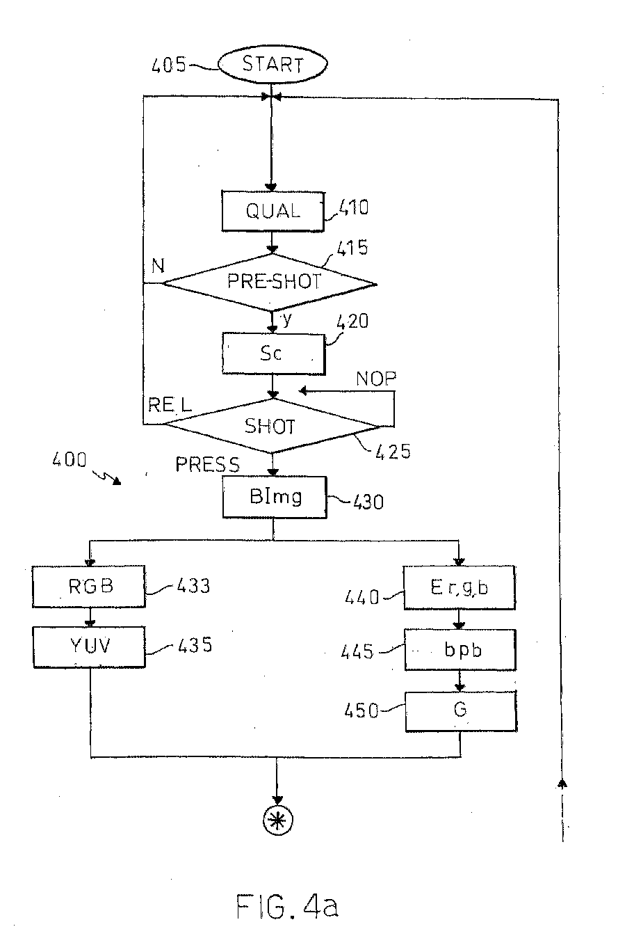
- Figg.4a-4b In order to explain the operation of the camera, reference is made to Figg.4a-4b (together with Fig.1).
- the microprocessor 170 runs the control program stored in the E 2 PROM 175.
- a method 400 corresponding to this control program starts at block 405 and then passes to block 410, wherein the user selects the desired quality of the image (such as low or high) by acting on the corresponding button; the microprocessor 170 determines and stores onto the SDARM 165 the target compression factor bp t corresponding to the selected image quality (for example, 1 bit/pel for the low quality and 2 bit/pel for the high quality).
- the method checks at block 415 if the shot button has been partially pressed in order to focus the image; if not, the method returns to block 410; as soon as the user partially presses the shot button, the method proceeds to block 420, wherein the incomplete digital image SImg is acquired by the sensor unit 110 (the diaphragm is always open and the light is focused by the lenses, through the Bayer filter, onto the CCD).
- the pre-processing unit 125 controls the acquisition unit 115 (by means of the control signals Sc) according to the content of the incomplete digital image SImg.
- the method checks again the status of the shot button at block 425. If the shot button has been released, the method returns to block 410, whereas if the shot button has been completely pressed (in order to take a photo) the method continues to block 430; on the other hand, if no action is performed by the user, the method stays in block 425 in an idle loop.
- the incomplete digital image SImg is acquired by the sensor unit 110 and modified by the pre-processing unit 125; the corresponding incomplete digital image BImg is stored onto the SDRAM 165.
- the method then forks into two branches which are executed concurrently.
- a first branch consists of blocks 433-435, and a second branch consists of blocks 440-450; the two branches joint at block 455 (described in the following).
- the incomplete digital image BImg is read from the SDRAM 165 and provided to the image-processing unit 130.
- the image-processing unit 130 interpolates the missing colour components in each element of the incomplete digital image BImg, in order to obtain the corresponding digital image RGB, and modifies the digital image RGB to improve the image quality.
- the method passes to block 435, wherein the digital image RGB is converted into the corresponding digital image YUV.
- the incomplete digital image BImg (read from the SDRAM 165) is also provided to the energy unit 190 at block 440; the energy unit 190 calculates the energy measures Er, Eg and Eb.
- the method proceeds to block 445, wherein the microprocessor 170 receives the energy measures Er,g,b and estimates the basic compression factor bp b using the parameters Cr,Cg,Cb,C read from the E 2 PROM 175.
- the microprocessor reads the parameters C2,C1,C0 associated with the target compression factor bp t from the E 2 PROM 175 (addressing the look-up table by the value of the target compression factor bp t ); the microprocessor 170 then estimates the gain factor G for obtaining the target compression factor bp t using the read parameters C2,C1,C0.
- the digital image YUV is provided to the DCT unit 140 which calculates the groups of DCT coefficients DCTy,u,v.
- the microprocessor 170 reads the quantization tables Qy,Quv from the E 2 PROM 175 and calculates the scaled quantization tables SQy,SQuv multiplying the respective quantization tables Qy,Quv by the gain factor G.
- the groups of DCT coefficients DCTy,u,v and the scaled quantization tables SQy,SQuv are provided to the quantizer 150, which generates the corresponding groups of quantized DCT coefficients QDCTy,u,v.
- the method proceeds to block 470, wherein the quantized DCT coefficients QDCTy,u,v are transformed into the vector ZZ by the zigzag unit 155.
- the vector ZZ is provided to the encoder 160 at block 475, which generates the corresponding compressed digital image JImg; the compressed digital image JImg is then stored onto the SDRAM 165.
- the compressed digital image JImg is read from the SDRAM 165 and sent to the memory card 180.
- the method than checks at block 485 if a stop condition has occurred, for example if the user has switched off the camera 100 (acting on the on/off button) or if the memory card 180 is full. If not, the method returns to block 410; on the other end, the method ends at block 490.
- FIG.5a the elements corresponding to the ones of Fig.1 are denoted with the same reference numbers and their explanation is omitted for the sake of simplicity
- the figure depicts a camera 500 with a control unit 515; the control unit 515 differs from the one described above in that no distinct energy unit is provided; on the other hand, an auto-focus unit 530 of the pre-processing unit 125 supplies the energy measures Er,g,b, which are sent onto the bus 120.
- the auto-focus unit 530 includes a block similar to the energy unit described above (wherein the energy measures are preferably estimated using Sobel filters).
- the microprocessor 175 controls the camera 500 running a program similar to the one described above.
- This solution is particularly advantageous, in that the gain factor is estimated using values already computed by the auto-focus unit; therefore, this structure is faster and further reduces the power consumption. Moreover, the camera is very simple, since no additional unit is required.
Abstract
Description


| 1 | 11 | 10 | 16 | 24 | 40 | 51 | 61 |
| 12 | 12 | 14 | 19 | 26 | 58 | 60 | 55 |
| 14 | 13 | 16 | 24 | 40 | 57 | 69 | 56 |
| 14 | 17 | 22 | 29 | 51 | 87 | 8 | 62 |
| 18 | 22 | 37 | 56 | 68 | 109 | 203 | 77 |
| 24 | 35 | 55 | 64 | 81 | 104 | 113 | 92 |
| 49 | 64 | 78 | 87 | 103 | 121 | 120 | 101 |
| 72 | 92 | 95 | 98 | 112 | 100 | 103 | 99 |
| 1 | 18 | 24 | 47 | 99 | 99 | 99 | 99 |
| 18 | 21 | 26 | 66 | 99 | 99 | 99 | 99 |
| 24 | 26 | 56 | 99 | 99 | 99 | 99 | 99 |
| 47 | 66 | 99 | 99 | 99 | 99 | 99 | 99 |
| 99 | 66 | 99 | 99 | 99 | 99 | 99 | 99 |
| 99 | 66 | 99 | 99 | 99 | 99 | 99 | 99 |
| 99 | 66 | 99 | 99 | 99 | 99 | 99 | 99 |
| 99 | 66 | 99 | 99 | 99 | 99 | 99 | 99 |


Claims (17)
- A method (400) of compressing a digital image including a matrix of elements each one consisting of a plurality of digital components of different type representing a pixel, the method comprising the steps of:providing (410-430) an incomplete digital image wherein at least one component is missing in each element,obtaining (433-435) the digital image from the incomplete digital image,splitting (455) the digital image into a plurality of blocks and calculating, for each block, a group of DCT coefficients for the components of each type,quantizing (460-465) the DCT coefficients of each group using a corresponding quantization table scaled by a gain factor for achieving a target compression factor,
characterized by the steps ofdetermining (440) at least one energy measure of the incomplete digital image,estimating (445-450) the gain factor as a function of the at least one energy measure, the function being determined experimentally according to the target compression factor. - The method (400) according to claim 1, wherein the step (445-450) of estimating the gain factor includes the steps of:estimating (445) a basic compression factor provided by the quantization tables scaled by a pre-set factor as a first function of the at least one energy measure,estimating (450) the gain factor as a second function of the basic compression factor, the first function and the second function being determined experimentally according to the target compression factor.
- The method (400) according to claim 2, wherein the first function is a linear function and the second function is a quadratic function.
- The method (400) according to claim 2 or 3, further comprising the steps of:storing a plurality of sets of parameters representing the second function, each set of parameters being associated with a corresponding value of the target compression factor,selecting (410) an image quality and determining a current value of the target compression factor as a function of the selected image quality,reading (450) the parameters associated with the current value of the target compression factor and estimating the gain factor using the read parameters.
- The method (400) according to any claim from 2 to 4, wherein the pre-set factor is determined experimentally according to the target compression factor.
- The method (400) according to any claim from 1 to 5, wherein each element of the incomplete digital image consists of a single component chosen between a red component, a green component, and a blue component, the elements of the incomplete digital image being arranged in a Bayer pattern.
- The method (400) according to claim 6, wherein each element of the digital image consists of a luminance component, a first chrominance component, and a second chrominance component, the step (433-435) of obtaining the digital image from the incomplete digital image comprising the steps of:interpolating (433) the missing red component, green component and blue component for each element of the incomplete digital image,calculating (435) the luminance component, the first chrominance component and the second chrominance component for each element of the digital image from the corresponding red component, green component and blue component.
- The method (400) according to claim 6 or 7, wherein the at least one energy measure consists of an energy measure of the red components, an energy measure of the green components and an energy measure of the blue components.
- The method (400) according to claim 6 or 7, wherein the at least one energy measure consists of an energy measure of the green components.
- The method (400) according to claim 8 or 9, wherein the step (440) of determining the at least one energy measure comprises, for each type of component, the steps of:calculating, for each element of the incomplete digital image consisting of said type of component, a first absolute value of the difference between the element and a first adjacent element consisting of said type of component along a first direction, and a second absolute value of the difference between the element and a second adjacent element consisting of said type of component along a second direction perpendicular to the first direction, andsumming the first absolute values and the second absolute values.
- The method (400) according to claim 10, wherein at least one quantization table is asymmetric along the first direction and the second direction, the method further comprising the steps of:multiplying each first absolute value by a correction factor for compensating the asymmetry of the at least one quantization table.
- The method (400) according to any claim from 1 to 11, further comprising the step of controlling (420) an automatic focus of the incomplete digital image using the at least one energy measure.
- A device (115) for compressing a digital image including a matrix of elements each one consisting of a plurality of digital components of different type representing a pixel, the device (115) comprising means (125) for providing an incomplete digital image wherein at least one component is missing in each element, means (130) for obtaining the digital image from the incomplete digital image, means (145) for splitting the digital image into a plurality of blocks and calculating, for each block, a group of DCT coefficients for the components of each type, means (150) for quantizing the DCT coefficients of each group using a corresponding quantization table scaled by a gain factor for achieving a target compression factor,
characterized in thatthe device (115) further includes means (190) for determining at least one energy measure of the incomplete digital image, and means (170) for estimating the gain factor as a function of the at least one energy measure, the function being determined experimentally according to the target compression factor. - The device (115) according to claim 13, further comprising a pre-processing unit (125) including the means for providing the incomplete digital image, an image-processing unit (130) comprising the means for obtaining the digital image, a compression unit (135) comprising the means (145) for splitting the digital image and for calculating the DCT coefficients and the means (150) for quantizing the DCT coefficients, a memory unit (175) for storing the quantization tables, an energy unit (190) including the means for determining the at least one energy measure, a processor unit (170) for controlling the device (115), communication means (120) for connecting the pre-processing unit, the image-processing unit, the compression unit, the memory unit, the energy unit and the processor unit therebetween, the processor unit (170) estimating the gain factor under the control of a program stored onto the memory unit (175).
- The device (515) according to claim 13, further comprising means (530) for controlling an automatic focus of the incomplete digital image using the at least one energy measure.
- The device (515) according to claim 15, further comprising a pre-processing unit (125) including the means for providing the incomplete digital image, an image-processing unit (130) comprising the means for obtaining the digital image, a compression unit (135) comprising the means (145) for splitting the digital image and for calculating the DCT coefficients and the means (150) for quantizing the DCT coefficients, a memory unit (175) for storing the quantization tables, an auto-focus unit (530) including the means for determining the at least one energy measure and the means for controlling the automatic focus, a processor unit (170) for controlling the device (515), communication means (120) for connecting the pre-processing unit, the image-processing unit, the compression unit, the memory unit, the auto-focus unit and the processor unit therebetween, the processor unit (170) estimating the gain factor under the control of a program stored onto the memory unit (175).
- A digital still camera (100;500) comprising the device (115;515) of any claim from 13 to 16.
Priority Applications (3)
| Application Number | Priority Date | Filing Date | Title |
|---|---|---|---|
| EP00202438A EP1173026B1 (en) | 2000-07-10 | 2000-07-10 | A method of compressing digital images |
| DE60039689T DE60039689D1 (en) | 2000-07-10 | 2000-07-10 | Method of compressing digital images |
| US09/903,371 US6839467B2 (en) | 2000-07-10 | 2001-07-10 | Method of compressing digital images |
Applications Claiming Priority (1)
| Application Number | Priority Date | Filing Date | Title |
|---|---|---|---|
| EP00202438A EP1173026B1 (en) | 2000-07-10 | 2000-07-10 | A method of compressing digital images |
Publications (2)
| Publication Number | Publication Date |
|---|---|
| EP1173026A1 true EP1173026A1 (en) | 2002-01-16 |
| EP1173026B1 EP1173026B1 (en) | 2008-07-30 |
Family
ID=8171775
Family Applications (1)
| Application Number | Title | Priority Date | Filing Date |
|---|---|---|---|
| EP00202438A Expired - Lifetime EP1173026B1 (en) | 2000-07-10 | 2000-07-10 | A method of compressing digital images |
Country Status (3)
| Country | Link |
|---|---|
| US (1) | US6839467B2 (en) |
| EP (1) | EP1173026B1 (en) |
| DE (1) | DE60039689D1 (en) |
Cited By (1)
| Publication number | Priority date | Publication date | Assignee | Title |
|---|---|---|---|---|
| EP3635954A4 (en) * | 2017-04-21 | 2020-07-15 | Zenimax Media Inc. | Systems and methods for rendering & pre-encoded load estimation based encoder hinting |
Families Citing this family (11)
| Publication number | Priority date | Publication date | Assignee | Title |
|---|---|---|---|---|
| US7315388B2 (en) * | 2001-01-24 | 2008-01-01 | Canon Kabushiki Kaisha | Image input/output control apparatus, image processing apparatus, image processing method, data communication apparatus, and data communication method |
| US7046856B2 (en) * | 2001-11-07 | 2006-05-16 | Feria Erlan H | Accelerated predictive-transform |
| DE60114651T2 (en) | 2001-12-14 | 2006-06-01 | Stmicroelectronics S.R.L., Agrate Brianza | Method of compressing digital images recorded in color filter array format (CFA) |
| EP1326209B1 (en) * | 2001-12-24 | 2007-09-26 | STMicroelectronics S.r.l. | Method for contrast enhancement in colour digital image |
| US7130072B2 (en) * | 2002-02-08 | 2006-10-31 | Canon Kabushiki Kaisha | Multifunction system, image processing method, computer program and memory medium |
| EP1632902B1 (en) * | 2004-09-03 | 2007-12-05 | STMicroelectronics S.r.l. | Method for image compression, related system and computer product therefor |
| US7916103B2 (en) * | 2004-09-27 | 2011-03-29 | Qualcomm Mems Technologies, Inc. | System and method for display device with end-of-life phenomena |
| KR100601475B1 (en) * | 2004-12-09 | 2006-07-18 | 삼성전기주식회사 | Image compressor having variable quantization parameter in accordance with image complexity and method thereof |
| EP1755341A1 (en) * | 2005-08-19 | 2007-02-21 | Texas Instruments Incorporated | Method of quantization of transform coefficients |
| KR101035754B1 (en) * | 2006-02-13 | 2011-05-20 | 가부시끼가이샤 도시바 | Moving image encoding/decoding method and device |
| CN117292003B (en) * | 2023-11-27 | 2024-03-19 | 深圳对对科技有限公司 | Picture cloud data storage method for computer network |
Citations (5)
| Publication number | Priority date | Publication date | Assignee | Title |
|---|---|---|---|---|
| EP0566219A2 (en) * | 1991-04-23 | 1993-10-20 | Canon Kabushiki Kaisha | Image processing apparatus |
| WO1995004434A1 (en) * | 1993-07-27 | 1995-02-09 | Sri International | Method and apparatus for compression and decompression of digital color images |
| US5818529A (en) * | 1992-04-28 | 1998-10-06 | Mitsubishi Denki Kabushiki Kaisha | Variable length coding of video with controlled deletion of codewords |
| EP0899961A1 (en) * | 1997-08-25 | 1999-03-03 | Tektronix, Inc. | Pipelined processing for moving picture compression bit rate control |
| WO1999060793A1 (en) * | 1998-05-21 | 1999-11-25 | Intel Corporation | The compression of color images based on a 2-dimensional discrete wavelet transform yielding a perceptually lossless image |
Family Cites Families (7)
| Publication number | Priority date | Publication date | Assignee | Title |
|---|---|---|---|---|
| US6512791B1 (en) * | 1991-05-15 | 2003-01-28 | Canon Kabushiki Kaisha | Image processing apparatus having means for controlling exposure using an orthogonal transformation coefficient |
| US5339368A (en) * | 1991-11-21 | 1994-08-16 | Unisys Corporation | Document image compression system and method |
| US5949919A (en) * | 1995-10-05 | 1999-09-07 | Microsoft Corporation | Precompression extrapolation method |
| US5764814A (en) * | 1996-03-22 | 1998-06-09 | Microsoft Corporation | Representation and encoding of general arbitrary shapes |
| US6037988A (en) * | 1996-03-22 | 2000-03-14 | Microsoft Corp | Method for generating sprites for object-based coding sytems using masks and rounding average |
| CN1278385A (en) * | 1997-10-28 | 2000-12-27 | 西门子公司 | Method and device for processing ditigized image |
| US6760479B1 (en) * | 1999-10-22 | 2004-07-06 | Research Foundation Of The City University Of New York | Super predictive-transform coding |
-
2000
- 2000-07-10 EP EP00202438A patent/EP1173026B1/en not_active Expired - Lifetime
- 2000-07-10 DE DE60039689T patent/DE60039689D1/en not_active Expired - Lifetime
-
2001
- 2001-07-10 US US09/903,371 patent/US6839467B2/en not_active Expired - Lifetime
Patent Citations (5)
| Publication number | Priority date | Publication date | Assignee | Title |
|---|---|---|---|---|
| EP0566219A2 (en) * | 1991-04-23 | 1993-10-20 | Canon Kabushiki Kaisha | Image processing apparatus |
| US5818529A (en) * | 1992-04-28 | 1998-10-06 | Mitsubishi Denki Kabushiki Kaisha | Variable length coding of video with controlled deletion of codewords |
| WO1995004434A1 (en) * | 1993-07-27 | 1995-02-09 | Sri International | Method and apparatus for compression and decompression of digital color images |
| EP0899961A1 (en) * | 1997-08-25 | 1999-03-03 | Tektronix, Inc. | Pipelined processing for moving picture compression bit rate control |
| WO1999060793A1 (en) * | 1998-05-21 | 1999-11-25 | Intel Corporation | The compression of color images based on a 2-dimensional discrete wavelet transform yielding a perceptually lossless image |
Non-Patent Citations (3)
| Title |
|---|
| BALASUBRAMANIAN R ET AL: "SEQUENTIAL SCALAR QUANTIZATION OF COLOR IMAGES", JOURNAL OF ELECTRONIC IMAGING,US,SPIE + IS&T, vol. 3, no. 1, 1994, pages 45 - 59, XP000420583, ISSN: 1017-9909 * |
| MARCELLIN M W ET AL: "TRANSFORM CODING OF MONOCHROME AND COLOR IMAGES USING TRELLIS CODED QUANTIZATION", IEEE TRANSACTIONS ON CIRCUITS AND SYSTEMS FOR VIDEO TECHNOLOGY,US,IEEE INC. NEW YORK, vol. 3, no. 4, 1 August 1993 (1993-08-01), pages 270 - 276, XP000414653, ISSN: 1051-8215 * |
| MARTINEZ-URIEGAS E ET AL: "SPATIOCHROMATIC MULTIPLEXING: A COLOR IMAGE REPRESENTATION FOR DIGITAL PROCESSING AND COMPRESSION", PROCEEDINGS OF THE SPIE, 29 January 1996 (1996-01-29), XP002043437 * |
Cited By (3)
| Publication number | Priority date | Publication date | Assignee | Title |
|---|---|---|---|---|
| EP3635954A4 (en) * | 2017-04-21 | 2020-07-15 | Zenimax Media Inc. | Systems and methods for rendering & pre-encoded load estimation based encoder hinting |
| RU2753157C2 (en) * | 2017-04-21 | 2021-08-12 | Зенимакс Медиа Инк. | Systems and methods for issuing prompts to encoder based on estimation of pre-coded load |
| US11503313B2 (en) | 2017-04-21 | 2022-11-15 | Zenimax Media Inc. | Systems and methods for rendering and pre-encoded load estimation based encoder hinting |
Also Published As
| Publication number | Publication date |
|---|---|
| EP1173026B1 (en) | 2008-07-30 |
| US20030063807A1 (en) | 2003-04-03 |
| DE60039689D1 (en) | 2008-09-11 |
| US6839467B2 (en) | 2005-01-04 |
Similar Documents
| Publication | Publication Date | Title |
|---|---|---|
| US8233060B2 (en) | Image data processing apparatus, image data processing method, and program | |
| US8538174B2 (en) | Image processing device | |
| US7358988B1 (en) | Image signal processor for performing image processing appropriate for an output device and method therefor | |
| US8724898B2 (en) | Signal processor and storage medium storing signal processing program | |
| KR20080038137A (en) | Digital signal encoding and decoding device and method | |
| KR100504649B1 (en) | Device for compressing image data | |
| EP1173026B1 (en) | A method of compressing digital images | |
| JP2019106572A (en) | Image encoding apparatus, and control method and program thereof | |
| US6990240B2 (en) | Image processing apparatus | |
| US7116832B2 (en) | Method of compressing digital images | |
| EP1173024B1 (en) | A method of compressing digital images | |
| EP0877524B1 (en) | Digital photography apparatus with an image-processing unit | |
| JP3795932B2 (en) | Image data compression encoding method and apparatus | |
| JP3858528B2 (en) | Electronic camera and recording medium on which image processing program is recorded | |
| KR20100011288A (en) | Method of compressing images, computer-readable medium storing program to perform the same and apparatus of photographing digital images | |
| JPH02105686A (en) | Digital recorder for still picture | |
| JP7256629B2 (en) | Image encoding device and its control method and program | |
| JP3568103B2 (en) | Image compression device | |
| JP3082050B2 (en) | Digital electronic still camera | |
| JP3192133B2 (en) | Electronic camera device | |
| KR100634568B1 (en) | Method for processing image signal capable of controlling jpeg file size and apparatus thereof | |
| JPH10257432A (en) | Image compression recording device | |
| JP2003163947A (en) | Image-compression method, program, and digital camera | |
| JPH06141215A (en) | Digital electronic still camera | |
| JP2004172674A (en) | Image encoder, image processor, image encoding method, image processing method, program thereof, and recording medium |
Legal Events
| Date | Code | Title | Description |
|---|---|---|---|
| PUAI | Public reference made under article 153(3) epc to a published international application that has entered the european phase |
Free format text: ORIGINAL CODE: 0009012 |
|
| AK | Designated contracting states |
Kind code of ref document: A1 Designated state(s): AT BE CH CY DE DK ES FI FR GB GR IE IT LI LU MC NL PT SE Kind code of ref document: A1 Designated state(s): DE FR GB IT |
|
| AX | Request for extension of the european patent |
Free format text: AL;LT;LV;MK;RO;SI |
|
| 17P | Request for examination filed |
Effective date: 20020626 |
|
| AKX | Designation fees paid |
Free format text: DE FR GB IT |
|
| GRAP | Despatch of communication of intention to grant a patent |
Free format text: ORIGINAL CODE: EPIDOSNIGR1 |
|
| GRAS | Grant fee paid |
Free format text: ORIGINAL CODE: EPIDOSNIGR3 |
|
| GRAA | (expected) grant |
Free format text: ORIGINAL CODE: 0009210 |
|
| AK | Designated contracting states |
Kind code of ref document: B1 Designated state(s): DE FR GB IT |
|
| REG | Reference to a national code |
Ref country code: GB Ref legal event code: FG4D |
|
| REF | Corresponds to: |
Ref document number: 60039689 Country of ref document: DE Date of ref document: 20080911 Kind code of ref document: P |
|
| PLBE | No opposition filed within time limit |
Free format text: ORIGINAL CODE: 0009261 |
|
| STAA | Information on the status of an ep patent application or granted ep patent |
Free format text: STATUS: NO OPPOSITION FILED WITHIN TIME LIMIT |
|
| 26N | No opposition filed |
Effective date: 20090506 |
|
| PG25 | Lapsed in a contracting state [announced via postgrant information from national office to epo] |
Ref country code: IT Free format text: LAPSE BECAUSE OF FAILURE TO SUBMIT A TRANSLATION OF THE DESCRIPTION OR TO PAY THE FEE WITHIN THE PRESCRIBED TIME-LIMIT Effective date: 20080730 |
|
| GBPC | Gb: european patent ceased through non-payment of renewal fee |
Effective date: 20090710 |
|
| REG | Reference to a national code |
Ref country code: FR Ref legal event code: ST Effective date: 20100331 |
|
| PG25 | Lapsed in a contracting state [announced via postgrant information from national office to epo] |
Ref country code: FR Free format text: LAPSE BECAUSE OF NON-PAYMENT OF DUE FEES Effective date: 20090731 |
|
| PG25 | Lapsed in a contracting state [announced via postgrant information from national office to epo] |
Ref country code: GB Free format text: LAPSE BECAUSE OF NON-PAYMENT OF DUE FEES Effective date: 20090710 |
|
| PGFP | Annual fee paid to national office [announced via postgrant information from national office to epo] |
Ref country code: DE Payment date: 20190620 Year of fee payment: 20 |
|
| REG | Reference to a national code |
Ref country code: DE Ref legal event code: R071 Ref document number: 60039689 Country of ref document: DE |