EP1185080B1 - Color image processing method and apparatus, and storage medium - Google Patents
Color image processing method and apparatus, and storage medium Download PDFInfo
- Publication number
- EP1185080B1 EP1185080B1 EP01306737A EP01306737A EP1185080B1 EP 1185080 B1 EP1185080 B1 EP 1185080B1 EP 01306737 A EP01306737 A EP 01306737A EP 01306737 A EP01306737 A EP 01306737A EP 1185080 B1 EP1185080 B1 EP 1185080B1
- Authority
- EP
- European Patent Office
- Prior art keywords
- unit
- color
- mfp
- image
- developing
- Prior art date
- Legal status (The legal status is an assumption and is not a legal conclusion. Google has not performed a legal analysis and makes no representation as to the accuracy of the status listed.)
- Expired - Lifetime
Links
- 238000003672 processing method Methods 0.000 title claims description 5
- 238000000034 method Methods 0.000 claims description 76
- 230000008569 process Effects 0.000 claims description 61
- 238000012937 correction Methods 0.000 claims description 32
- 238000012545 processing Methods 0.000 claims description 17
- 230000006870 function Effects 0.000 description 41
- 238000010586 diagram Methods 0.000 description 24
- 238000006243 chemical reaction Methods 0.000 description 19
- 239000003086 colorant Substances 0.000 description 14
- 238000012986 modification Methods 0.000 description 7
- 230000004048 modification Effects 0.000 description 7
- 230000008859 change Effects 0.000 description 5
- 230000006835 compression Effects 0.000 description 5
- 238000007906 compression Methods 0.000 description 5
- 239000004359 castor oil Substances 0.000 description 4
- 239000011159 matrix material Substances 0.000 description 4
- 239000000203 mixture Substances 0.000 description 4
- 238000012546 transfer Methods 0.000 description 4
- 238000005286 illumination Methods 0.000 description 3
- 230000003287 optical effect Effects 0.000 description 3
- 239000004065 semiconductor Substances 0.000 description 3
- 230000003595 spectral effect Effects 0.000 description 3
- 238000012360 testing method Methods 0.000 description 3
- XEKOWRVHYACXOJ-UHFFFAOYSA-N Ethyl acetate Chemical compound CCOC(C)=O XEKOWRVHYACXOJ-UHFFFAOYSA-N 0.000 description 2
- 238000004891 communication Methods 0.000 description 2
- 238000011161 development Methods 0.000 description 2
- 238000009826 distribution Methods 0.000 description 2
- 230000000873 masking effect Effects 0.000 description 2
- 238000005303 weighing Methods 0.000 description 2
- 241000931526 Acer campestre Species 0.000 description 1
- 238000012935 Averaging Methods 0.000 description 1
- 239000004364 Benzylated hydrocarbon Substances 0.000 description 1
- 239000004358 Butane-1, 3-diol Substances 0.000 description 1
- 238000003705 background correction Methods 0.000 description 1
- 230000000593 degrading effect Effects 0.000 description 1
- 230000001419 dependent effect Effects 0.000 description 1
- 238000006073 displacement reaction Methods 0.000 description 1
- 238000007730 finishing process Methods 0.000 description 1
- 238000007429 general method Methods 0.000 description 1
- 239000011521 glass Substances 0.000 description 1
- 239000003292 glue Substances 0.000 description 1
- 238000009499 grossing Methods 0.000 description 1
- 230000014759 maintenance of location Effects 0.000 description 1
- 230000002093 peripheral effect Effects 0.000 description 1
- 238000009877 rendering Methods 0.000 description 1
- 230000035945 sensitivity Effects 0.000 description 1
- 238000009966 trimming Methods 0.000 description 1
- 230000003442 weekly effect Effects 0.000 description 1
Images


Classifications
-
- H—ELECTRICITY
- H04—ELECTRIC COMMUNICATION TECHNIQUE
- H04N—PICTORIAL COMMUNICATION, e.g. TELEVISION
- H04N1/00—Scanning, transmission or reproduction of documents or the like, e.g. facsimile transmission; Details thereof
- H04N1/46—Colour picture communication systems
- H04N1/56—Processing of colour picture signals
- H04N1/60—Colour correction or control
- H04N1/603—Colour correction or control controlled by characteristics of the picture signal generator or the picture reproducer
- H04N1/6052—Matching two or more picture signal generators or two or more picture reproducers
-
- H—ELECTRICITY
- H04—ELECTRIC COMMUNICATION TECHNIQUE
- H04N—PICTORIAL COMMUNICATION, e.g. TELEVISION
- H04N1/00—Scanning, transmission or reproduction of documents or the like, e.g. facsimile transmission; Details thereof
- H04N1/46—Colour picture communication systems
- H04N1/56—Processing of colour picture signals
- H04N1/60—Colour correction or control
- H04N1/603—Colour correction or control controlled by characteristics of the picture signal generator or the picture reproducer
Definitions
- the present invention relates to an image processing method and apparatus for processing an input job in parallel at a plurality of color image output apparatus, and to a storage medium storing a program realizing such a method.
- a user selects a desired printer by using a printer driver and an application running on a computer, and instructs a print job via a public line such as a LAN and a dedicated interface.
- a server/client system is well known in which a client user sends a job via a document server to a printer.
- a document made of a large number of pages such as a manual and an operation instruction document or documents of a large number of volumes from publishing companies are often requested to be printed.
- the concept of cluster print has been proposed in which one document in a server or client is printed by a plurality of printers at the same time.
- Color documents are also prevailing and cluster print for color documents is being desired.
- Cluster print for color documents poses a problem of a difference between hues of output samples printed by printers, this problem not being associated with cluster print for white and black documents.
- An environment change or secular change of each printer can be mitigated to some degree by calibrating the printer.
- a plurality of printers have characteristics specific to them, a minute difference therebetween appears in output samples.
- a difference between hues of output samples printed out at the same time becomes a critical issue to a user.
- a difference between hues of printers of the same type is less conspicuous, a difference between hues of printers of different type is more conspicuous.
- JP2001-157069 discloses a color management system in which the output profile of each connected output device is detected to obtain a color reproducing area (an area within a color space which can be reproduced by each output device). The AND of all the color reproducing areas is obtained as a common color reproducing area. The range of color information of image data in picture editing is restricted to color information in the common color reproducing area and thus the compression of the color space is not required on outputting an image to each output device.
- US6035103 describes a method for providing color correction to a color marking engine, including generating a test pattern. An offset bit value of an image in the test pattern determined to be closest to a true gray is applied to the marking engine.
- US5642208 discloses an image forming system with a plurality of image forming apparatuses, configured to reduce a memory capacity of the entire system whilst maintaining a high copy volume.
- Color adjustment for printer is generally included in a series of processes called RIP processes of converting PDL data into bit map data. Only the color matching process cannot be used independently. In order to print out data from a plurality of color MFP's, it is necessary to perform the RIP process a plurality of times so that it takes a double RIP time.
- the present invention has been made in consideration of the above-described disadvantages and aims to process input image data in parallel at a plurality of color image output apparatus at high speed, while reducing the number of RIP processes of developing the input image data into bit map image data.
- an image processing method for processing an input job in parallel by a plurality of color image output apparatus comprising: a developing step of developing input image data into bit map image data, wherein the developing step includes first and second modes, wherein the first mode develops the input image data a plurality of times by using a color processing condition corresponding to each of the plurality of color image output apparatus, wherein and the second mode develops the input image data by using an optional color processing condition and outputs a result obtained in said developing step to the plurality of color image output apparatus.
- an image processing method for processing an input job in parallel by a plurality of color image output apparatus comprising: a developing step of developing input image data into bit map image data for a first color image output apparatus; and a converting step of converting the bit map image data for the first color image output apparatus into bit map image data for a second color image output apparatus, wherein the bit map image data for the first color image output apparatus developed by the developing step is transferred to the first color image output apparatus, and wherein the bit map image data for the second color image output apparatus converted by the converting step is transferred to the second color image output apparatus.
- FIGs. 1 and 2 are schematic diagrams showing examples of the structure of a system according to an embodiment.
- a network 101 is divided into two series in order to improve the performance of the system.
- Two series of the network shown in Fig. 1 are called a public network 101a and a private network 101b.
- the system configuration is not limited only to those shown in Figs. 1 and 2 , but other configurations may also be used.
- a document server 102 has two network interface cards (NIC) for two hardware series.
- One NIC 111 is connected to the public network 101a, and the other NIC 112 is connected to the private network 101b connected to printers.
- Computers 103a, 103b and 103c are clients which send a job to the document server. Although not shown, a number of other clients are connected to the public network. Clients are represented collectively hereinafter by a reference numeral 103.
- Multi function peripherals (MFP's) 105 are connected to the private network 101b.
- MFP 105 can scan and print a monochromatic image or a color image at a low resolution or in a binary state.
- MFP's as well as scanners, printers and FAXes are also connected to the private network 101b.
- An MFP 104 is a full color MFP capable of scanning and printing a full color image at a high resolution and at a high gradation level. Although MFP 104 may be connected to the private network 101b, it is connected to the document server 102 via a specific interface card 113 in order to allow a plurality of bits to be transferred at the same time, because it handles a great amount of data to be transferred.
- At least two full color MFP's 104a and 104b are controlled.
- Two specific I/F cards 113 are provided to control the full color MFP's 104a and 104b independently.
- a mother board 110 with a CPU, a memory and the like has NIC's 111 and 112 and exclusive I/F cards 113 connected via a PCI bus.
- the client computer 103 creates and edits various documents and figures by using an application program which executes desk top publishing (DTP).
- the created document/figure data is converted into page description language (PDL) by the client computer 103, and transferred via the network 101a to MFP 104 or 105 to be printed out.
- PDL page description language
- MFP 104, 105 has communication means capable of exchanging information with the document server 102 via the network 101b or an exclusive interface 109 (109a, 109b). Information and the status of MFP 104, 105 are supplied when necessary to the document server 102 or to the client computer 103 via the document server 102.
- the document server 102 (or client 103) has utility software for processing the information received from MFP 104, 105 which is controlled by the computer 102 (or client 103).
- MFP 104, 105 With reference to Figs. 3 to 11 , the structure of MFP 104, 105 will be described. A difference between MFP 104 and MFP 105 is whether a full color image or a monochromatic image is processed.
- the full color apparatus often includes the functions other than color processing function of the monochromatic apparatus. From these reason, the description is mainly directed to the full color apparatus, and the description for the monochromatic apparatus will be given when necessary.
- MFP 104, 105 has a scanner unit 201 for reading an image, a scanner IP unit 202 for processing image data, a NIC unit 204 for transferring image data and apparatus information via the network, and an exclusive I/F unit 205 for exchanging information with the full color MFP 104.
- a core unit 206 temporarily stores image data and determines a route depending upon the status of MFP 104, 105.
- Image data output from the core unit 206 is supplied to a printer unit 209 via a printer IP unit 207 and a PWM unit 208. Paper sheets printed out at the printer unit 209 are sent to a finisher unit 210 which performs a finishing process such as sorting and finishing.
- An original (manuscript) 302 to be read is placed on an original support glass 301.
- the original 302 is illuminated with an illumination lamp 303, and reflected light is focussed upon a CCD 308 via mirrors 304, 305 and 306 and a lens 307.
- a first mirror unit 310 including the mirror 304 and illumination lamp 303 moves at a speed v
- a second mirror unit 311 including the mirrors 305 and 306 moves at a speed 1/2 v, to thereby scan the whole area of the original 302.
- the first and second mirror units 310 and 311 are driven by a motor 309.
- the scanner IP unit 202 will be described.
- An input optical signal is converted into an electrical signal by a CCD sensor 308.
- the CCD sensor 308 is a color sensor having RGB three lines, and R (red), G (green) and B (blue) image signals are input to an A/D conversion unit 401 which performs a gain adjustment and an offset adjustment and thereafter converts the image signals into 8-bit digital color image signals R0, G0 and B0.
- a shading unit 402 performs a well-known shading correction for each color by using a signal read from a reference white plate. Since respective color line sensors of the CCD sensor 308 are disposed spaced apart by a predetermined distance, a line delay adjustment circuit (line interpolation unit) 403 corrects the spatial displacement in the sub-scan direction.
- an input masking unit 404 converts a read color space determined by the spectral characteristics of R, G and B filters of the CCD sensor 308 into the NTSC standard color space. Specifically, it converts input (R0, G0, B0) signals into standard (R, G, B) signals by a 3 x 3 matrix calculation using constants which are specific to the apparatus and are obtained by taking into consideration the sensitivity characteristics of the CCD sensor 308, the spectral characteristics of the illumination lamp and the like.
- a luminance/density conversion unit (LOG conversion unit) 405 is made of a look-up table (LUT) RAM, and converts RGB luminance signals into density signals of C1 (cyan), M1 (magenta) and Y1 (yellow).
- LUT look-up table
- the NIC unit 204 provides a function of interfacing with the network 101. Data is transferred to and from the external by using an Ethernet cable such as 10 Base-T and 100 Base-TX.
- the exclusive I/F unit 205 provides a function of interfacing with the full color MFP 104 and transferring CMYK signals of multi bits.
- the exclusive I/F unit 205 transfers image data of four colors of 8 bits and includes communication lines. If data is transmitted via an Ethernet cable, the transfer speed is insufficient for MFP 104 and the performance of other devices connected to the network is sacrificed. From these reasons, the exclusive parallel interface is used.
- the bus selector unit 221 of the core nit 206 provides a function of routing control of MFP 104, 105. Namely, the bus selector unit 221 selects a bus in accordance with various functions of MFP 104, 105 such as copy function, network scan function, network print function, and a display function.
- Image data output from the bus selector 221 is supplied to the printer unit 209 via the compression unit 222, memory unit 223 of large capacity such as a hard disk drive (HDD) and expansion unit 224.
- the compression method to be used by the compression unit 222 may be general methods such as JPEG, JBIG and ZIP.
- the compressed image data is managed for each job and stored together with additional data such as a file name, a creator name, a creation date and time, and a file size.
- a job number and a password are stored together, it is possible to support a personal box function. This function is used for preventing data in HDD from being temporarily stored or printed out by persons other than limited persons. If a print-out of a stored job is designated, authentication of the password is performed and then the job is read from the memory unit 223 and image expansion is performed to recover raster images which are sent to the printer unit 207.
- An output masking/UCR circuit unit 501 converts M1, C1 and Y1 signals into Y (yellow), M (magenta) C (cyan) and K (black) signals matching toner colors of the image forming apparatus, by a matrix calculation. This conversion is performed in accordance with the toner spectral distribution characteristics.
- a gamma correction unit 502 performs correction by using a look-up table (LUT) RAM while considering the characteristics of hue and the like such as the toner gradation characteristics.
- a spatial filter 503 performs sharpness correction and smoothing correction and outputs image singles to the PWM unit 208.
- Image data of yellow (Y), magenta (M), cyan (C) and black (K) of four separated colors (single color for MFP 105) output from the printer IP unit 207 is used for forming images by the PWM unit 208.
- a signal ( Fig. 8-1 ) from a triangular wave generating unit 801 and a signal ( Fig. 8-2 ) from a D/A converter 802 for converting an input digital image signal into an analog signal are compared by a comparator 803 which outputs a signal shown in Fig. 8-3 .
- This signal is supplied to a laser drive unit 804, and respective laser units 805 converts CMYK signals into laser beams.
- Each laser beam is scanned by a polygon mirror 913 and applied to each of photosensitive drums 917, 921, 925 and 929.
- Fig. 9 is a schematic diagram showing the color printer unit.
- Four laser beams emitted from the four semiconductor laser units 805 are applied to a polygon mirror 913.
- One of the four laser beams scans the photosensitive drum 917 via mirrors 914, 915 and 916.
- Another laser beam scans the photosensitive drum 921 via mirrors 918, 919 and 920.
- Another laser beam scans the photosensitive drum 925 via mirrors 922, 923 and 924.
- Another laser beam scans the photosensitive drum 929 via mirrors 926, 927 and 928.
- a developer 930 supplies yellow (Y) toner and forms a yellow toner image on the photosensitive drum 917 in accordance with the laser beam.
- a developer 931 supplies magenta (M) toner and forms a magenta toner image on the photosensitive drum 921 in accordance with the laser beam.
- a developer 932 supplies cyan (C) toner and forms a cyan toner image on the photosensitive drum 925 in accordance with the laser beam.
- a developer 933 supplies black (K) toner and forms a black toner image on the photosensitive drum 929 in accordance with the laser beam. Toner images of four colors (Y, M, C, K) are transferred to a sheet so that a full color output image can be formed.
- a sheet supplied from either a sheet cassette 934, 935 or a manual tray 936 is sucked to a transfer belt 938 via registration rollers 937 and transported. Synchronously with paper feed timing, respective color toners are developed beforehand on the photosensitive drums 917, 921, 925 and 929. As the sheet is transported, each toner is transferred to the sheet. The sheet transferred with respective toners is separated and transported by a transport belt 939, and toners are fixed to the sheet by a fixing unit 940. The sheet passed through the fixing unit 940 is guided once downward by a flapper 950. After the back end of the sheet passes through the flapper 950, the sheet is switched back and ejected out. Therefore, the sheet is ejected in a face-down state so that printed-out sheets are arranged in the correct page order starting from the top page.
- the four photosensitive drums 917, 921, 925 and 929 are disposed at an equal interval of a distance d.
- a sheet is transported at a constant speed v by the transport belt 939. Synchronously with this transport, the four semiconductor laser units 805 are driven.
- Fig. 10 is a schematic diagram showing the monochromatic printer unit.
- Four laser beams emitted from the four semiconductor laser units 805 are applied to a polygon mirror 1013. Each laser beam scans a photosensitive drum 1017 via mirrors 1014, 1015 and 1016.
- a developer 1030 supplies black toner and forms a toner image on the photosensitive drum 1017 in accordance with the laser beam to obtain an output image.
- a sheet supplied from either a sheet cassette 1034, 1035 or a manual tray 1036 is sucked to a transfer belt 1038 via registration rollers 1037 and transported. Synchronously with paper feed timing, toner is developed beforehand on the photosensitive drums 1017. As the sheet is transported, the toner is transferred to the sheet. The sheet transferred with the toner is separated and the toner is fixed to the sheet by a fixing unit 1040. The sheet passed through the fixing unit 1040 is guided once downward by a flapper 1050. After the back end of the sheet passes through the flapper 1050, the sheet is switched back and ejected out. Therefore, the sheet is ejected in a face-down state so that printed-out sheets are arranged in the correct page order starting from the top page.
- Fig. 11 is a schematic diagram showing the finisher unit.
- a sheet output from the fixing unit 940 (or 1040) of the printer unit 209 enters the finisher unit 210.
- the finisher unit 210 has a sample tray 1101 and a stack tray 1102. Each sheet is ejected out in accordance with the type of a job and the number of sheets to be ejected.
- sorting methods There are two sorting methods. One is a bin sorting method of sorting sheets into a plurality of bins. The other is a shift sorting method using an electronic sorting function to be described later, the method sorting sheets for each job by shifting a bin (or tray) forward along the depth direction.
- the electronic sorting function is called a collate function.
- the collate function exchanges a page order buffered in the large capacity memory of the core unit with a page eject order.
- a grouping function sorts sheets for each page instead of for each job.
- sheets before ejection may be stored for each job to bind the sheets with a stapler 1105 immediately before they are ejected.
- a Z folding machine 1104 for folding a sheet in a Z-character shape and a puncher 1106 for forming two (or three) holes through sheets for filing are provided.
- the Z folding machine and puncher are used in accordance with the type of a job.
- a saddle stitcher 1107 binds sheets at two positions in the sheet center area and then squeezes the center area by rollers to fold the sheets by halves and form a booklet such as a weekly magazine and a pamphlet. Sheets bound with the saddle stitcher 1107 is ejected from a booklet tray 1108.
- a function of binding with glue may also be provided.
- An inserter 1103 is used for sending sheets set to a tray 1110 to one of the trays 1101, 1102 and 1108 without sending them to the printer. It is therefore possible to insert a sheet set to the inserter 1103 between sheets supplied to the finisher 209. Sheets in the face-up state are set to the tray 1110 of the inserter 1103, and the sheets are fed by pickup rollers 1111 starting from the uppermost sheet. Therefore, the sheets from the inserter 1103 are directly transported by pickup rollers 1111 to the tray 1101, 1102 to eject them in the face-down state. When sheets are sent to the saddle stitcher 1107, they are once transported to the puncher 1106 side and then switched back to obtain the same face direction.
- a job input from NIC 111 is supplied to the server via an input device control unit 1201.
- the job is processed in the server by using various client applications.
- PDL data and JCL (job control language) data are accepted.
- client requests are processed.
- This module outputs data obtained by combining proper PDL and JCL data.
- An input job control unit 1202 forms a job list for managing a list of requests by jobs and accessing each job supplied to the server.
- This module has a job routing function of determining a job route and a job scheduling function of determining a job order.
- a rasterizing (RIP) unit 1203 performs an RIP process for PDL to create a bit map having a proper size and resolution.
- the RIP unit 1203 can perform a rasterizing process for data having various formats such as PostScript (registered trademark of Adobe Systems Incorporated), PCL, TIFF, JPEG and PDF.
- a data conversion unit 1204 performs compression and format conversion of a bit map image formed by the RIP unit, and selects the optimum image type matching each printer. For example, if a job is to be processed in the page unit, a PDF header is added to the bit map data of TIFF, JPEG or the like rasterized by the RIP unit, and the bit map image is edited as PDF data.
- an output job control unit 1205 manages how a page image of the job is processed. For example, the page image is printed by a printer or saved in a hard disk drive (HDD) 1207. It is also possible to judge whether or not the printed job is to be saved in the hard disk drive (HDD) 1207. If saved, it may be called again.
- the output job control unit 1205 also manages the cooperation between the hard disk drive (HDD) 1207 and a RAM 1208.
- An output device control unit 1206 controls to select a device whereat a job is output and to select devices for clustering (printing by a plurality printers at the same time).
- the output device control unit 1206 also monitors the status of the device 104, 105 and supplies the device status to the document server 102.
- a device for developing data described with PDL (Page Description Language), typically PostScript (registered trademark of Adobe Systems Incorporated), into bit map data capable of print and display, is generally called a RIP (Raster Image Processor).
- RIP may be realized by hardware or software, which is called a hardware RIP or a software RIP.
- Fig. 13 shows the structure of the RIP unit 1203.
- the RIP unit 1203 is constituted of a rasterizing unit 1301, a CMS (Color Management System) unit 1302 and a TRC (Tone Reproduction Curve) unit 1303.
- the rasterizing unit 1301 converts PDL data into bit map data having a resolution matching print and display.
- the CMS unit 1302 manages colors, and the TRC unit 1303 performs a gamma correction for maintaining linearity of CMYK colors.
- PDL data is generally classified into the following factors, and an original image is constituted of a combination of these factors.
- Fig. 14 shows a description example of PDL data in left side
- Fig. 14 shows the development result of the PDL data shown in right side of Fig. 14 .
- L1411 is a description of designating a character color, the densities of C, M, Y and B being indicated between the parentheses.
- a minimum value of a color designation command is 0.0 and a maximum value is 1.0.
- L1411 indicates that the character is black.
- L1412 substitutes a character string "IC" in a variable String 1.
- First and second parameters in L1413 indicate the X- and Y-coordinate values of the start position of a sheet on which the character string is laid out.
- the third parameter indicates the size of the character
- the fourth parameter indicates the space between characters
- the fifth parameter indicates the character string to be laid out.
- L1413 therefore instructs to lay out the character string "IC" from the coordinate (0.0, 0.0) at the size of 0.3 and a space of 0.1.
- figure information R1402. Similar to L1411, L1421 designates a line color, in this example, cyan is designated. L1422 designates to draw a line. First and second parameters indicate the X- and Y-coordinate values of a start position of the line, and third and fourth parameters indicate the X-and Y-coordinate values of an end position of the line. The fifth parameter indicates a width of the line.
- L1431 substitutes a raster image into a variable image 1.
- the first parameter indicates the type of the raster image and the number of color compositions.
- the second parameter indicates the number of bits per one color composition.
- the third and fourth parameters indicate the size of the raster image in the X- and Y-directions.
- the fifth and following parameters represent raster image data.
- the number of raster image data pieces corresponds to a product of the number of color compositions constituting one pixel and the image size in the X- and Y- directions.
- Fig. 14 shows the development result of the raster image data obtained by analyzing the three image descriptions of one page.
- R1401, R1402 and R1403 are obtained by developing PDL data.
- This raster image data is actually developed in RAM 1208 (or image disk 1207) for each of CMYK colors.
- PDL data sent from the client 103 is directly written in RAM 1208 (or image disk 1207) or it is developed into a raster image and then written.
- the stored data is maintained to be stored when necessary.
- CMS Cosmetic Management System
- the CMS unit 1302 shown in Fig. 13 performs color matching by selecting a conversion table source profile 1304 or a conversion table printer profile 1305, which is a so-called ICC (International Color Consortium) profile. Namely, input image data is processed by using the correction conditions of the characteristics of input image data described in the source profile and the correction conditions of the characteristics of a printer described in the printer profile.
- ICC International Color Consortium
- PDL data includes two kinds, RGB series and CMYK series.
- the latter PDL data (mainly PostScript) is generated by some applications capable of processing data in the unit of CMYK, such as Photoshop and Illustrator (registered trademarks of Adobe Systems Incorporated).
- the former PDL data (mainly Postscript) is generated by other applications, and includes data having the format of TIFF and JPEG.
- the ICC profile stores a sequence formula train, a multi-dimension look-up table and the like.
- conversion by using a sequence formula is used.
- Similar processes may be used also for other types such as three-dimension look-up tables.
- the source profile 1304 may be profiles of various displays typically S-RGB or profiles for various input devices such as digital cameras and scanners, and stores a sequence formula ⁇ a00,..., a22 ⁇ for each type of devices.
- the CMYK data is once converted into a standardized L*a*b* space by using a formula E1502 stored in the printer profile.
- a formula E1502 stored in the printer profile.
- the L*a*b* is converted into the CMYK data matching the printer.
- data is printed by MFP 104a so that conversion is performed by using the formula E1503.
- This sequence formula ⁇ c00,..., c32 ⁇ is prepared for each type of printers. For example, if MFP 104a and MFP 104b are different types, E1503 is a profile for MFP 104a, whereas E1504 is a profile for MFP 104b. If a target device is changed, another profile is selected.
- a plurality of sequence formulas may be prepared to select one of them in accordance with a method of adjusting a difference of the reproduction range between displays, input devices and output devices, which method is called rendering intent such as "perceptual (hue retention)”, “colormetric (minimum color difference)” and “saturation (saturation preference)”.
- the TRC unit 1303 performs a gamma conversion of a value of each of the CMYK colors having eight bits (0 to 255) in accordance with the gradation characteristics of each printer.
- a linear table G0 such as shown in Fig. 16-1 does not show linear gradation characteristics.
- a chart such as shown in Fig. 18 is output and the output density is measured with a density meter
- an output result G1 is such as shown in Fig. 16-2 .
- a gamma table Ga such as shown in Fig. 16-3 , which is a reverse gamma function of Gi ( Fig. 16-2 ), is used for the conversion by the TRC unit to obtain a linear print output such as shown in Fig. 16-1 .
- the gradation characteristics of a printer represented by Gi changes with time because of the environment change such as a temperature and humidity, a secular change from turn-on of a printer power source and a print start, and a durability change such as the total number of printed sheets and the consumption degree of consumables. Therefore, a linear image cannot be obtained unless the gamma table is replaced routinely.
- a calibration tool is constituted of three steps, a step of printing a chart such as shown in Fig. 18 from a printer, a step of reading a patch density of each portion of the printed-out chart sample, and a step of correcting the gamma table of the TRC unit in accordance with the read patch density.
- the scanner unit 201 or a density meter may be used.
- the gamma table of the TRC unit is specific to each device. Therefore, if the same PDL data is output from two color MFP's at the same time, it cannot ensure the linearity of each color MFP.
- Input PDL data is once stored in the hard disk drive (HDD) 1207 and subjected to the RIP process twice.
- the first RIP process correction is performed by using the gamma table 1701 of MFP 104a to generate CMYK data specific to MFP 104a and output the data to MFP 104a.
- the second RIP process correction is performed by using the gamma table 1702 of MFP 104b to generate CMYK data specific to MFP 104b and output the data to MFP 104b.
- the RIP process is performed twice.
- the RIP modules 1203a and 1203b use respective gamma tables 1701 and 1702.
- one gamma table is used.
- a new gamma table Gc 1801 is used which is obtained by averaging two gamma tables Ga 1701 and Gb 1702, so that the RIP process for both MFP 104a and MFP 104b can be performed at the same time.
- the gamma table Gc is not necessarily required to use average values, but one of the gamma tables Ga and Gb may be used as a representative one. In forming an averaged gamma table, it is necessary to obtain an average value of each of the CMYK colors.
- a buffer memory 1802 is provided with synchronization between the server computer 102 and respective MFP's.
- raster data of each of the CMYK colors stored in the buffer memory may be stored also in the hard disk drive (HDD) 1207.
- a high image quality mode and a high speed mode may be provided to allow a user to select one of them.
- the RIP process is performed twice by sequentially using the gamma tables for MFP 104a and MFP 104b.
- the RIP process is performed once by using an average gamma table or a predetermined one of the gamma tables for MFP 104a and MFP 104b, and the data is supplied to MFP 104a and MFP 104b at the same time.
- Information of the selection of the high image quality mode or high speed mode is added to the header information of a job, to allow the mode to be automatically selected during the job processing.
- the RIP process is executed a plurality of times by using the gamma table corresponding to each color MFP.
- a process using the gamma table corresponding to each color MFP is executed by using the gamma conversion unit 502 ( Fig. 6 ) of each MFP.
- a rasterizing process is executed by using the rasterizing unit 1401 and a color matching process is executed by using the CMS unit 1402, without executing the gamma conversion process using TRC 1403.
- the gamma conversion unit 502 of each color MFP can be controlled externally (e.g., from the document server), the gamma conversion unit 502 of each color MFP is used as the TRC unit 1403 so that a cluster print using a plurality of color MFP's of the same type can be performed with a high image quality and by a single RIP process.
- the calibrated gamma table is downloaded in the gamma conversion unit 502.
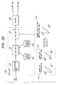
- printer profile 1405 Since the printer profile 1405 is different for each type, coincidence of hues cannot be obtained even if the gamma tables of the TRC units 1403 of MFP's of different types are changed.
- the high image quality mode is used in which the printer profile 1405 is changed for the first and second RIP processes and the RIP process is executed twice.
- a profile Pa 1901 is a profile for MFP 104a and corresponds to the sequence formula E1503 shown in Fig. 15 . If the type of MFP 104b is different, the values specific to this device also become different and a profile Pb 1902 is used. The gamma tables Ga and Gb also become different for the first and second RIP processes and are sent to the devices MFP 104a and MFP 104b.
- PDL data output from the rasterized unit 1401 is once stored in a hard disk drive (HDD) 1207 and by using printer profiles 1901 and 1902 and gamma tables 1701 and 1702, the data is output to MFP's 104a and 104b.
- HDD hard disk drive
- the high image quality mode can be realized by using printer profiles and gamma tables for the first, second, third,..., RIP processes, and the high speed mode can be realized by using an averaged printer profile and an averaged gamma table.
- the average values are not necessarily required to be used, but mode values or median values may also be used.
- the number of distributions of clustering is weighted in accordance with the print speed of each printer. As shown in Fig. 24 , if MFP 104a is 30 ppm and MFP 104b is 20 ppm, a weighted profile represented by a sequence formula E2201 is used. In this case, a cluster is made of two printers to complete printing at the same time. MFP 104a prints 30 sheets which are 3/5 of all sheets, and is given a weighing coefficient of 3/5, whereas MFP 104b prints 20 sheets which are 2/5 of all sheets, and is given a weighing coefficient of 2/5.
- One of the first to third embodiments may be selectively used for the cluster process in accordance with the type of a printer.
- a high image quality mode and a high speed mode are prepared for cluster print by at least two color MFP's 104 under the control of one server 102.
- the RIP process is executed twice for the cluster printing with hue matching each color MFP, whereas as a user selects the high speed mode, a plurality of MFP's perform the cluster printing at the same time by one RIP process to provide hue minimizing a difference between color MFP characteristics. In this manner, a color clustering system can be provided which satisfies both the needs of high image quality and high speed.
- This embodiment provides a method of generating data for each device by one RIP process by connecting a plurality of color MFP's 104 of the same type.
- one device e.g., MFP 104a
- another e.g., MFP 104b
- MFP 104a is a master
- MFP 104b is a slave.
- Data for the slave is obtained by correcting CMYK data for MFP 104a processed by using the gamma table for the master (MFP 104a) by using a correction gamma table unit 1801 for correcting data for MFP 104b.
- the CMYK data for MFP 104a is multiplied by the reverse function table Gi ( Fig. 16-2 ) of the gamma table Ga ( Fig. 16-3 ) for MFP 104a to obtain CMYK data before the TRC unit 1403. Then, the obtained CMYK data is multiplied by the gamma table Gb ( Fig. 17 ) for MFP 104b to obtain CMYK data matching MFP 104b.
- the number of combinations of cluster printing increases if three or more MFP's are connected.
- the relation of master and slave such as the first embodiment is not always realized.
- the combinations of cluster are (104a and 104b), (104b and 104c), (104c and 104b) and (104a and 104b and 104c). Therefore, even if MFP 104a is used as the master, there is a combination without the master. It is therefore necessary to prepare the correction table units for all MFP's 104a, 104b and 104c.
- a gamma table Ga for MFP 104a is set to the TRC unit 1403
- a linear gamma table G0 is set to a table correction unit 1901 for MFP 104a
- a gamma table (Gi*Gb) is set to a table correction unit 1902 for MFP 104b
- a gamma table (Gi*Gc where Gc is a gamma table for MFP 104c) is set to a table correction unit 1903 for MFP 104c.
- any combination can output always the corrected CMYK data by one RIP process to each color MFP.
- the cluster process using printers larger in number than the number of RIP units can be performed at high speed without degrading the quality of an output image.
- the gamma conversion unit 502 ( Fig. 6 ) of the MFP color printer may be used. Namely, the gamma conversion unit 502 of the slave color MFP may be used as the correction table unit. In this case, the gamma table is downloaded to the slave color MFP.
- a combination of color MFP's 104 for cluster print of different types will be described. Since the printer profile 1405 is different for each type, coincidence of hues is not possible even if the gamma tables of TRC units 1403 of different type of devices are changed.
- profile correction units 2001 and 2002 for correcting the printer profile 1405 are added as shown in Fig. 22 to correct a difference between colors of devices.
- a first method for this correction is to calculate approximate values of CMYK colors by using a look-up table (gamma table). This method is the same as that to be performed by the table correction unit. However, the look-up table can be integrated with the multiplied gamma table of the table correction unit.
- a second method is to use a function calculation of calculating CMYK values dependent upon the device by multiplying CMYK data by a sequence formula. For example, as shown in Fig. 23 , new CMYK data can be calculated by a matrix calculation such as E2003, or by using both the look-up table and matrix calculation.
- CMYK image data output from the RIP unit 1203 may be stored once in the hard disk drive (HDD) 1207, to output data corrected by respective correction tables to MFP 104a, MFP 104b, and other devices.
- HDD hard disk drive
- Each of the cluster print using a plurality of MFP's of the same type and the cluster print using a plurality of MFP's of different types can be automatically selected by making the document server 102 judge the type of an output printer.
- a master printer is set in accordance with a predetermined priority order or information designated by a user designated a job.
- the cluster print is performed by at least two color MFP's.
- Output data for the master is generated by performing a color correction matching the characteristics of the master color MFP, and output data for a slave color MFP is generated by preparing a correction table for correcting the master output data to the slave output data.
- a color clustering system can be provided which can perform the cluster print of image data matching the hue by a plurality of color MFP's at the same time and with a single RIP process.
- the software program codes themselves realize the embodiment function. Therefore, the program codes themselves and means for supplying the program codes, e.g., a storage medium storing the program codes, constitute the present invention.
- the storage medium for storing such program codes may be a floppy disk, a hard disk, an optical disk, a magneto optical disk, a CD-ROM, a magnetic tape, a nonvolatile memory card, a ROM or the like.
- program codes are included in the embodiment of the invention, wherein not only the computer executes the supplied program codes to realize the embodiment function but also the program codes in cooperation with an OS (operating system) running on the computer or with another application or the like realize the embodiment function.
Description
- The present invention relates to an image processing method and apparatus for processing an input job in parallel at a plurality of color image output apparatus, and to a storage medium storing a program realizing such a method.
- A user selects a desired printer by using a printer driver and an application running on a computer, and instructs a print job via a public line such as a LAN and a dedicated interface. A server/client system is well known in which a client user sends a job via a document server to a printer.
- In the market called a print-on-demand or the like, a document made of a large number of pages such as a manual and an operation instruction document or documents of a large number of volumes from publishing companies are often requested to be printed. In order to deal with such cases, the concept of cluster print has been proposed in which one document in a server or client is printed by a plurality of printers at the same time. Color documents are also prevailing and cluster print for color documents is being desired.
- Cluster print for color documents poses a problem of a difference between hues of output samples printed by printers, this problem not being associated with cluster print for white and black documents. An environment change or secular change of each printer can be mitigated to some degree by calibrating the printer. However, since a plurality of printers have characteristics specific to them, a minute difference therebetween appears in output samples. Regardless of the same document, a difference between hues of output samples printed out at the same time becomes a critical issue to a user. Although a difference between hues of printers of the same type is less conspicuous, a difference between hues of printers of different type is more conspicuous.
-
JP2001-157069 -
US6035103 describes a method for providing color correction to a color marking engine, including generating a test pattern. An offset bit value of an image in the test pattern determined to be closest to a true gray is applied to the marking engine. -
US5642208 discloses an image forming system with a plurality of image forming apparatuses, configured to reduce a memory capacity of the entire system whilst maintaining a high copy volume. - Color adjustment for printer is generally included in a series of processes called RIP processes of converting PDL data into bit map data. Only the color matching process cannot be used independently. In order to print out data from a plurality of color MFP's, it is necessary to perform the RIP process a plurality of times so that it takes a double RIP time.
- The present invention has been made in consideration of the above-described disadvantages and aims to process input image data in parallel at a plurality of color image output apparatus at high speed, while reducing the number of RIP processes of developing the input image data into bit map image data.
- It is also an object of the invention to allow a user to select either a high speed process or a high precision process.
- In order to achieve these objects of the invention, there is provided an image processing method for processing an input job in parallel by a plurality of color image output apparatus, comprising: a developing step of developing input image data into bit map image data, wherein the developing step includes first and second modes, wherein the first mode develops the input image data a plurality of times by using a color processing condition corresponding to each of the plurality of color image output apparatus, wherein and the second mode develops the input image data by using an optional color processing condition and outputs a result obtained in said developing step to the plurality of color image output apparatus.
- According to another aspect of the invention, there is provided an image processing method for processing an input job in parallel by a plurality of color image output apparatus, comprising: a developing step of developing input image data into bit map image data for a first color image output apparatus; and a converting step of converting the bit map image data for the first color image output apparatus into bit map image data for a second color image output apparatus, wherein the bit map image data for the first color image output apparatus developed by the developing step is transferred to the first color image output apparatus, and wherein the bit map image data for the second color image output apparatus converted by the converting step is transferred to the second color image output apparatus.
- Other objects and features of the present invention will become apparent from the following detailed description of embodiments when read in conjunction with the accompanying drawings.
-
-
Fig. 1 is a diagram showing the entirety of a system according to an embodiment of the invention. -
Fig. 2 is a diagram showing the entirety of a system according to another embodiment of the invention. -
Fig. 3 is a block diagram showing the entirety of an image forming apparatus. -
Fig. 4 is a diagram showing a scanner unit of the image forming apparatus. -
Fig. 5 is a diagram showing a scanner IP unit of the image forming apparatus. -
Fig. 6 is a diagram showing a printer IP unit of the image forming apparatus. -
Fig. 7 is a block diagram showing a PWM unit of the image forming apparatus. -
Fig. 8 is a timing chart illustrating the operation of the PWM unit of the image forming apparatus. -
Fig. 9 is a diagram showing a printer unit of a color image forming apparatus. -
Fig. 10 is a diagram showing a printer unit of a white and black image forming apparatus. -
Fig. 11 is a diagram showing a finisher unit of the image forming apparatus. -
Fig. 12 is a job flow inside of a document server according to the invention. -
Fig. 13 is a diagram showing the structure of an RIP unit. -
Fig. 14 shows a description example of PDL data and raster-developed data. -
Fig. 15 shows sequence formulas using a source profile and a printer profile. -
Figs. 16-1, 16-2, and 16-3 are diagrams showing gamma curves. -
Fig. 17 is a diagram showing a gamma curve. -
Fig. 18 is a test chart for calibration. -
Fig. 19 is a diagram showing the structure of the RIP unit. -
Fig. 20 is a diagram showing the structure of the RIP unit. -
Fig. 21 is a diagram showing the structure of the RIP unit. -
Fig. 22 shows sequence formulas using printer profiles. -
Fig. 23 is a diagram showing the structure of the RIP unit. -
Fig. 24 shows sequence formulas using printer profiles. -
Fig. 25 is a diagram showing the structure of an RIP unit. -
Fig. 26 is a diagram showing the structure of an RIP unit. -
Fig. 27 is a diagram showing the structure of an RIP unit. -
Fig. 28 shows a sequence formula for a profile correction unit. -
Figs. 1 and2 are schematic diagrams showing examples of the structure of a system according to an embodiment. - In the system shown in
Fig. 1 , anetwork 101 is divided into two series in order to improve the performance of the system. Two series of the network shown inFig. 1 are called apublic network 101a and aprivate network 101b. The system configuration is not limited only to those shown inFigs. 1 and2 , but other configurations may also be used. - A
document server 102 has two network interface cards (NIC) for two hardware series. One NIC 111 is connected to thepublic network 101a, and the other NIC 112 is connected to theprivate network 101b connected to printers. -
Computers - Multi function peripherals (MFP's) 105 are connected to the
private network 101b. MFP 105 can scan and print a monochromatic image or a color image at a low resolution or in a binary state. Although not shown, other MFP's as well as scanners, printers and FAXes are also connected to theprivate network 101b. - An MFP 104 is a full color MFP capable of scanning and printing a full color image at a high resolution and at a high gradation level. Although MFP 104 may be connected to the
private network 101b, it is connected to thedocument server 102 via aspecific interface card 113 in order to allow a plurality of bits to be transferred at the same time, because it handles a great amount of data to be transferred. - In this embodiment, at least two full color MFP's 104a and 104b are controlled. Two specific I/F cards 113 (113a and 113b) are provided to control the full color MFP's 104a and 104b independently.
- In the hardware structure of the
document server 102, amother board 110 with a CPU, a memory and the like has NIC's 111 and 112 and exclusive I/F cards 113 connected via a PCI bus. - The client computer 103 creates and edits various documents and figures by using an application program which executes desk top publishing (DTP). The created document/figure data is converted into page description language (PDL) by the client computer 103, and transferred via the
network 101a to MFP 104 or 105 to be printed out. - MFP 104, 105 has communication means capable of exchanging information with the
document server 102 via thenetwork 101b or an exclusive interface 109 (109a, 109b). Information and the status of MFP 104, 105 are supplied when necessary to thedocument server 102 or to the client computer 103 via thedocument server 102. The document server 102 (or client 103) has utility software for processing the information received from MFP 104, 105 which is controlled by the computer 102 (or client 103). - With reference to
Figs. 3 to 11 , the structure of MFP 104, 105 will be described. A difference between MFP 104 and MFP 105 is whether a full color image or a monochromatic image is processed. The full color apparatus often includes the functions other than color processing function of the monochromatic apparatus. From these reason, the description is mainly directed to the full color apparatus, and the description for the monochromatic apparatus will be given when necessary. - MFP 104, 105 has a
scanner unit 201 for reading an image, ascanner IP unit 202 for processing image data, aNIC unit 204 for transferring image data and apparatus information via the network, and an exclusive I/F unit 205 for exchanging information with the full color MFP 104. Acore unit 206 temporarily stores image data and determines a route depending upon the status of MFP 104, 105. - Image data output from the
core unit 206 is supplied to aprinter unit 209 via aprinter IP unit 207 and aPWM unit 208. Paper sheets printed out at theprinter unit 209 are sent to afinisher unit 210 which performs a finishing process such as sorting and finishing. - With reference to
Fig. 4 , the structure of thescanner unit 201 will be described. An original (manuscript) 302 to be read is placed on anoriginal support glass 301. The original 302 is illuminated with anillumination lamp 303, and reflected light is focussed upon aCCD 308 viamirrors lens 307. Afirst mirror unit 310 including themirror 304 andillumination lamp 303 moves at a speed v, and asecond mirror unit 311 including themirrors speed 1/2 v, to thereby scan the whole area of the original 302. The first andsecond mirror units motor 309. - With reference to
Fig. 5 , thescanner IP unit 202 will be described. An input optical signal is converted into an electrical signal by aCCD sensor 308. TheCCD sensor 308 is a color sensor having RGB three lines, and R (red), G (green) and B (blue) image signals are input to an A/D conversion unit 401 which performs a gain adjustment and an offset adjustment and thereafter converts the image signals into 8-bit digital color image signals R0, G0 and B0. Ashading unit 402 performs a well-known shading correction for each color by using a signal read from a reference white plate. Since respective color line sensors of theCCD sensor 308 are disposed spaced apart by a predetermined distance, a line delay adjustment circuit (line interpolation unit) 403 corrects the spatial displacement in the sub-scan direction. - Next, an
input masking unit 404 converts a read color space determined by the spectral characteristics of R, G and B filters of theCCD sensor 308 into the NTSC standard color space. Specifically, it converts input (R0, G0, B0) signals into standard (R, G, B) signals by a 3 x 3 matrix calculation using constants which are specific to the apparatus and are obtained by taking into consideration the sensitivity characteristics of theCCD sensor 308, the spectral characteristics of the illumination lamp and the like. - A luminance/density conversion unit (LOG conversion unit) 405 is made of a look-up table (LUT) RAM, and converts RGB luminance signals into density signals of C1 (cyan), M1 (magenta) and Y1 (yellow).
- The
NIC unit 204 provides a function of interfacing with thenetwork 101. Data is transferred to and from the external by using an Ethernet cable such as 10 Base-T and 100 Base-TX. - The exclusive I/
F unit 205 provides a function of interfacing with the full color MFP 104 and transferring CMYK signals of multi bits. The exclusive I/F unit 205 transfers image data of four colors of 8 bits and includes communication lines. If data is transmitted via an Ethernet cable, the transfer speed is insufficient for MFP 104 and the performance of other devices connected to the network is sacrificed. From these reasons, the exclusive parallel interface is used. - The
bus selector unit 221 of thecore nit 206 provides a function of routing control of MFP 104, 105. Namely, thebus selector unit 221 selects a bus in accordance with various functions of MFP 104, 105 such as copy function, network scan function, network print function, and a display function. - Bus selection patterns for executing each function are shown below.
copy function:scanner 201 →core 206 →printer 209
network scan function:scanner 201 →core 206 →NIC unit 204
network print function:NIC unit 204 →core 206 →printer 209 - Image data output from the
bus selector 221 is supplied to theprinter unit 209 via thecompression unit 222,memory unit 223 of large capacity such as a hard disk drive (HDD) andexpansion unit 224. The compression method to be used by thecompression unit 222 may be general methods such as JPEG, JBIG and ZIP. The compressed image data is managed for each job and stored together with additional data such as a file name, a creator name, a creation date and time, and a file size. - If a job number and a password are stored together, it is possible to support a personal box function. This function is used for preventing data in HDD from being temporarily stored or printed out by persons other than limited persons. If a print-out of a stored job is designated, authentication of the password is performed and then the job is read from the
memory unit 223 and image expansion is performed to recover raster images which are sent to theprinter unit 207. - With reference to
Fig. 6 , the printer IP unit will be described. An output masking/UCR circuit unit 501 converts M1, C1 and Y1 signals into Y (yellow), M (magenta) C (cyan) and K (black) signals matching toner colors of the image forming apparatus, by a matrix calculation. This conversion is performed in accordance with the toner spectral distribution characteristics. - A
gamma correction unit 502 performs correction by using a look-up table (LUT) RAM while considering the characteristics of hue and the like such as the toner gradation characteristics. Aspatial filter 503 performs sharpness correction and smoothing correction and outputs image singles to thePWM unit 208. - With reference to
Fig. 7 , thePWM unit 208 will be described. Image data of yellow (Y), magenta (M), cyan (C) and black (K) of four separated colors (single color for MFP 105) output from theprinter IP unit 207 is used for forming images by thePWM unit 208. A signal (Fig. 8-1 ) from a triangularwave generating unit 801 and a signal (Fig. 8-2 ) from a D/A converter 802 for converting an input digital image signal into an analog signal are compared by acomparator 803 which outputs a signal shown inFig. 8-3 . This signal is supplied to alaser drive unit 804, andrespective laser units 805 converts CMYK signals into laser beams. - Each laser beam is scanned by a
polygon mirror 913 and applied to each ofphotosensitive drums -
Fig. 9 is a schematic diagram showing the color printer unit. Four laser beams emitted from the foursemiconductor laser units 805 are applied to apolygon mirror 913. One of the four laser beams scans thephotosensitive drum 917 viamirrors photosensitive drum 921 viamirrors photosensitive drum 925 viamirrors photosensitive drum 929 viamirrors - A
developer 930 supplies yellow (Y) toner and forms a yellow toner image on thephotosensitive drum 917 in accordance with the laser beam. Adeveloper 931 supplies magenta (M) toner and forms a magenta toner image on thephotosensitive drum 921 in accordance with the laser beam. Adeveloper 932 supplies cyan (C) toner and forms a cyan toner image on thephotosensitive drum 925 in accordance with the laser beam. Adeveloper 933 supplies black (K) toner and forms a black toner image on thephotosensitive drum 929 in accordance with the laser beam. Toner images of four colors (Y, M, C, K) are transferred to a sheet so that a full color output image can be formed. - A sheet supplied from either a
sheet cassette manual tray 936 is sucked to atransfer belt 938 viaregistration rollers 937 and transported. Synchronously with paper feed timing, respective color toners are developed beforehand on thephotosensitive drums transport belt 939, and toners are fixed to the sheet by a fixingunit 940. The sheet passed through the fixingunit 940 is guided once downward by a flapper 950. After the back end of the sheet passes through the flapper 950, the sheet is switched back and ejected out. Therefore, the sheet is ejected in a face-down state so that printed-out sheets are arranged in the correct page order starting from the top page. - The four
photosensitive drums transport belt 939. Synchronously with this transport, the foursemiconductor laser units 805 are driven. -
Fig. 10 is a schematic diagram showing the monochromatic printer unit. Four laser beams emitted from the foursemiconductor laser units 805 are applied to apolygon mirror 1013. Each laser beam scans aphotosensitive drum 1017 viamirrors developer 1030 supplies black toner and forms a toner image on thephotosensitive drum 1017 in accordance with the laser beam to obtain an output image. - A sheet supplied from either a
sheet cassette manual tray 1036 is sucked to atransfer belt 1038 viaregistration rollers 1037 and transported. Synchronously with paper feed timing, toner is developed beforehand on thephotosensitive drums 1017. As the sheet is transported, the toner is transferred to the sheet. The sheet transferred with the toner is separated and the toner is fixed to the sheet by afixing unit 1040. The sheet passed through thefixing unit 1040 is guided once downward by a flapper 1050. After the back end of the sheet passes through the flapper 1050, the sheet is switched back and ejected out. Therefore, the sheet is ejected in a face-down state so that printed-out sheets are arranged in the correct page order starting from the top page. -
Fig. 11 is a schematic diagram showing the finisher unit. A sheet output from the fixing unit 940 (or 1040) of theprinter unit 209 enters thefinisher unit 210. Thefinisher unit 210 has asample tray 1101 and astack tray 1102. Each sheet is ejected out in accordance with the type of a job and the number of sheets to be ejected. - There are two sorting methods. One is a bin sorting method of sorting sheets into a plurality of bins. The other is a shift sorting method using an electronic sorting function to be described later, the method sorting sheets for each job by shifting a bin (or tray) forward along the depth direction. The electronic sorting function is called a collate function. The collate function exchanges a page order buffered in the large capacity memory of the core unit with a page eject order. A grouping function sorts sheets for each page instead of for each job.
- When a sheet is ejected to the
stack tray 1102, sheets before ejection may be stored for each job to bind the sheets with astapler 1105 immediately before they are ejected. - On the route to the two trays, a
Z folding machine 1104 for folding a sheet in a Z-character shape and apuncher 1106 for forming two (or three) holes through sheets for filing are provided. The Z folding machine and puncher are used in accordance with the type of a job. - A
saddle stitcher 1107 binds sheets at two positions in the sheet center area and then squeezes the center area by rollers to fold the sheets by halves and form a booklet such as a weekly magazine and a pamphlet. Sheets bound with thesaddle stitcher 1107 is ejected from abooklet tray 1108. - Although not shown in
Fig. 11 , a function of binding with glue, a function of trimming side edges opposite to the bound sides and the like may also be provided. - An
inserter 1103 is used for sending sheets set to atray 1110 to one of thetrays inserter 1103 between sheets supplied to thefinisher 209. Sheets in the face-up state are set to thetray 1110 of theinserter 1103, and the sheets are fed bypickup rollers 1111 starting from the uppermost sheet. Therefore, the sheets from theinserter 1103 are directly transported bypickup rollers 1111 to thetray saddle stitcher 1107, they are once transported to thepuncher 1106 side and then switched back to obtain the same face direction. - With reference to
Fig. 12 , thedocument server 102 will be described. - A job input from
NIC 111 is supplied to the server via an inputdevice control unit 1201. The job is processed in the server by using various client applications. As input data, PDL data and JCL (job control language) data are accepted. By using status information of printers and the server, client requests are processed. This module outputs data obtained by combining proper PDL and JCL data. - An input
job control unit 1202 forms a job list for managing a list of requests by jobs and accessing each job supplied to the server. This module has a job routing function of determining a job route and a job scheduling function of determining a job order. - A rasterizing (RIP)
unit 1203 performs an RIP process for PDL to create a bit map having a proper size and resolution. TheRIP unit 1203 can perform a rasterizing process for data having various formats such as PostScript (registered trademark of Adobe Systems Incorporated), PCL, TIFF, JPEG and PDF. - A
data conversion unit 1204 performs compression and format conversion of a bit map image formed by the RIP unit, and selects the optimum image type matching each printer. For example, if a job is to be processed in the page unit, a PDF header is added to the bit map data of TIFF, JPEG or the like rasterized by the RIP unit, and the bit map image is edited as PDF data. - In accordance with command settings, an output
job control unit 1205 manages how a page image of the job is processed. For example, the page image is printed by a printer or saved in a hard disk drive (HDD) 1207. It is also possible to judge whether or not the printed job is to be saved in the hard disk drive (HDD) 1207. If saved, it may be called again. The outputjob control unit 1205 also manages the cooperation between the hard disk drive (HDD) 1207 and aRAM 1208. - An output
device control unit 1206 controls to select a device whereat a job is output and to select devices for clustering (printing by a plurality printers at the same time). The outputdevice control unit 1206 also monitors the status of the device 104, 105 and supplies the device status to thedocument server 102. - A device for developing data described with PDL (Page Description Language), typically PostScript (registered trademark of Adobe Systems Incorporated), into bit map data capable of print and display, is generally called a RIP (Raster Image Processor). RIP may be realized by hardware or software, which is called a hardware RIP or a software RIP.
-
Fig. 13 shows the structure of theRIP unit 1203. TheRIP unit 1203 is constituted of arasterizing unit 1301, a CMS (Color Management System)unit 1302 and a TRC (Tone Reproduction Curve)unit 1303. Therasterizing unit 1301 converts PDL data into bit map data having a resolution matching print and display. TheCMS unit 1302 manages colors, and theTRC unit 1303 performs a gamma correction for maintaining linearity of CMYK colors. - PDL data is generally classified into the following factors, and an original image is constituted of a combination of these factors.
- (a) Image description by character codes
- (b) Image description by figure codes
- (c) Image description by raster image data
-
Fig. 14 shows a description example of PDL data in left side, andFig. 14 shows the development result of the PDL data shown in right side ofFig. 14 . - A description example of character information will be described by using character information R1401. L1411 is a description of designating a character color, the densities of C, M, Y and B being indicated between the parentheses. A minimum value of a color designation command is 0.0 and a maximum value is 1.0. L1411 indicates that the character is black. L1412 substitutes a character string "IC" in a
variable String 1. First and second parameters in L1413 indicate the X- and Y-coordinate values of the start position of a sheet on which the character string is laid out. The third parameter indicates the size of the character, the fourth parameter indicates the space between characters, and the fifth parameter indicates the character string to be laid out. L1413 therefore instructs to lay out the character string "IC" from the coordinate (0.0, 0.0) at the size of 0.3 and a space of 0.1. - A description example of figure information will be described by using figure information R1402. Similar to L1411, L1421 designates a line color, in this example, cyan is designated. L1422 designates to draw a line. First and second parameters indicate the X- and Y-coordinate values of a start position of the line, and third and fourth parameters indicate the X-and Y-coordinate values of an end position of the line. The fifth parameter indicates a width of the line.
- A description example of raster image information will be described by using raster image information R1403. L1431 substitutes a raster image into a
variable image 1. The first parameter indicates the type of the raster image and the number of color compositions. The second parameter indicates the number of bits per one color composition. The third and fourth parameters indicate the size of the raster image in the X- and Y-directions. The fifth and following parameters represent raster image data. The number of raster image data pieces corresponds to a product of the number of color compositions constituting one pixel and the image size in the X- and Y- directions. In L1431, since the CMYK image is constituted of four color compositions (cyan, magenta, yellow and black), the number of raster image data pieces is (4 × 5 × 5) = 100. L1432 indicates that theimage 1 is laid out from the coordinate (0.0, 0.5) at a size of 0.5 × 0.5. -
Fig. 14 (right side) shows the development result of the raster image data obtained by analyzing the three image descriptions of one page. R1401, R1402 and R1403 are obtained by developing PDL data. This raster image data is actually developed in RAM 1208 (or image disk 1207) for each of CMYK colors. For example, the portion of R1401 is written inRAM 1208 for each of CMYK colors as C = 0, M = 0, Y = 0, and K = 255, and the portion of R1402 is written as C = 255, M = 0, Y = 0 and K = 0. - In the
document server 102, PDL data sent from the client 103 (or document server itself) is directly written in RAM 1208 (or image disk 1207) or it is developed into a raster image and then written. The stored data is maintained to be stored when necessary. - The
CMS unit 1302 shown inFig. 13 performs color matching by selecting a conversiontable source profile 1304 or a conversiontable printer profile 1305, which is a so-called ICC (International Color Consortium) profile. Namely, input image data is processed by using the correction conditions of the characteristics of input image data described in the source profile and the correction conditions of the characteristics of a printer described in the printer profile. - PDL data includes two kinds, RGB series and CMYK series. The latter PDL data (mainly PostScript) is generated by some applications capable of processing data in the unit of CMYK, such as Photoshop and Illustrator (registered trademarks of Adobe Systems Incorporated). The former PDL data (mainly Postscript) is generated by other applications, and includes data having the format of TIFF and JPEG.
- Generally, the ICC profile stores a sequence formula train, a multi-dimension look-up table and the like. In this embodiment, in order to simplify the description, conversion by using a sequence formula is used. Similar processes may be used also for other types such as three-dimension look-up tables.
- When PDL data of the RGB series is input, the RGB data is once converted into a standardized L*a*b* space by using a formula E1501 shown in
Fig. 15 stored in the source profile. Thesource profile 1304 may be profiles of various displays typically S-RGB or profiles for various input devices such as digital cameras and scanners, and stores a sequence formula {a00,..., a22} for each type of devices. - Similarly, when PDL data of the CMYK series is input, the CMYK data is once converted into a standardized L*a*b* space by using a formula E1502 stored in the printer profile. When an ink color reproduction such as SWOP, Euroscale and JapanColor is to be simulated, it is necessary to store a sequence formula {b00,..., b23} corresponding to not only the type of a printer but also a subject to be simulated.
- Next, the L*a*b* is converted into the CMYK data matching the printer. In this embodiment, data is printed by
MFP 104a so that conversion is performed by using the formula E1503. - This sequence formula {c00,..., c32} is prepared for each type of printers. For example, if
MFP 104a andMFP 104b are different types, E1503 is a profile forMFP 104a, whereas E1504 is a profile forMFP 104b. If a target device is changed, another profile is selected. - For the printer profile, a plurality of sequence formulas may be prepared to select one of them in accordance with a method of adjusting a difference of the reproduction range between displays, input devices and output devices, which method is called rendering intent such as "perceptual (hue retention)", "colormetric (minimum color difference)" and "saturation (saturation preference)".
- The reason why data is once converted into the standardized space is to always ensure the equivalent hue even if colors under the various input environments such as scanners and displays are output under various output environments such as printers.
- The
TRC unit 1303 performs a gamma conversion of a value of each of the CMYK colors having eight bits (0 to 255) in accordance with the gradation characteristics of each printer. Generally, an input signal converted by using a linear table G0 such as shown inFig. 16-1 does not show linear gradation characteristics. For example, if a chart such as shown inFig. 18 is output and the output density is measured with a density meter, then an output result G1 is such as shown inFig. 16-2 . To solve this problem, a gamma table Ga such as shown inFig. 16-3 , which is a reverse gamma function of Gi (Fig. 16-2 ), is used for the conversion by the TRC unit to obtain a linear print output such as shown inFig. 16-1 . - Gi and Ga are reverse function gamma tables and Ga * Gi = G0 so that the linear output results G0 can be obtained.
- The gradation characteristics of a printer represented by Gi changes with time because of the environment change such as a temperature and humidity, a secular change from turn-on of a printer power source and a print start, and a durability change such as the total number of printed sheets and the consumption degree of consumables. Therefore, a linear image cannot be obtained unless the gamma table is replaced routinely.
- It is therefore necessary to use a tool for calibration (linearization). A calibration tool is constituted of three steps, a step of printing a chart such as shown in
Fig. 18 from a printer, a step of reading a patch density of each portion of the printed-out chart sample, and a step of correcting the gamma table of the TRC unit in accordance with the read patch density. In order to read the patch density, thescanner unit 201 or a density meter may be used. - The outline of the system and each unit of each apparatus is used in common by each embodiment of the invention. In the second and following embodiments, the same structure is represented by using an identical reference numeral and the description thereof is omitted.
- The gamma table of the TRC unit is specific to each device. Therefore, if the same PDL data is output from two color MFP's at the same time, it cannot ensure the linearity of each color MFP.
- In order to solve this problem, it is conceivable to perform the RIP process twice as shown in
Fig. 19 . Input PDL data is once stored in the hard disk drive (HDD) 1207 and subjected to the RIP process twice. In the first RIP process, correction is performed by using the gamma table 1701 ofMFP 104a to generate CMYK data specific toMFP 104a and output the data toMFP 104a. In the second RIP process, correction is performed by using the gamma table 1702 ofMFP 104b to generate CMYK data specific toMFP 104b and output the data toMFP 104b. In this case that only oneRIP unit 1203 is used, the RIP process is performed twice. - In the case that there are two RIP units 1203a and 1203b, parallel processing using the two RIP units is performed at a high speed. The RIP modules 1203a and 1203b use respective gamma tables 1701 and 1702.
- With the above-described method of performing the RIP process twice, an image having a high quality and a hue suitable for each device can be printed. However, the RIP time is doubled because of the two RIP processes so that the print performance is sacrificed.
- Consider therefore printing an image with one RIP process. In order to print an image with one RIP process, one gamma table is used. For example, as shown in
Fig. 20 , a newgamma table Gc 1801 is used which is obtained by averaging twogamma tables Ga 1701 andGb 1702, so that the RIP process for bothMFP 104a andMFP 104b can be performed at the same time. - The gamma table Gc is not necessarily required to use average values, but one of the gamma tables Ga and Gb may be used as a representative one. In forming an averaged gamma table, it is necessary to obtain an average value of each of the CMYK colors.
- In order to operate
MFP 104a andMFP 104b independently, abuffer memory 1802 is provided with synchronization between theserver computer 102 and respective MFP's. By taking into consideration an operation stop of one of MFP's 104 because of jam or error, raster data of each of the CMYK colors stored in the buffer memory may be stored also in the hard disk drive (HDD) 1207. - A high image quality mode and a high speed mode may be provided to allow a user to select one of them. When the high image quality mode is selected, the RIP process is performed twice by sequentially using the gamma tables for
MFP 104a andMFP 104b. When the high speed mode is selected, the RIP process is performed once by using an average gamma table or a predetermined one of the gamma tables forMFP 104a andMFP 104b, and the data is supplied toMFP 104a andMFP 104b at the same time. - Information of the selection of the high image quality mode or high speed mode is added to the header information of a job, to allow the mode to be automatically selected during the job processing.
- In the first embodiment, during the high image quality mode, the RIP process is executed a plurality of times by using the gamma table corresponding to each color MFP. In contrast, in this modification, a process using the gamma table corresponding to each color MFP is executed by using the gamma conversion unit 502 (
Fig. 6 ) of each MFP. - Therefore, in the modification, in the
RIP unit 1203, a rasterizing process is executed by using therasterizing unit 1401 and a color matching process is executed by using theCMS unit 1402, without executing the gamma conversionprocess using TRC 1403. - If the
gamma conversion unit 502 of each color MFP can be controlled externally (e.g., from the document server), thegamma conversion unit 502 of each color MFP is used as theTRC unit 1403 so that a cluster print using a plurality of color MFP's of the same type can be performed with a high image quality and by a single RIP process. - If the gamma table is calibrated by using a calibration tool, the calibrated gamma table is downloaded in the
gamma conversion unit 502. - In the first embodiment, color MFP's of the same type are connected. In the second embodiment, a modification of the first embodiment will be described in which two color MFP's of different types are connected.
- Since the
printer profile 1405 is different for each type, coincidence of hues cannot be obtained even if the gamma tables of theTRC units 1403 of MFP's of different types are changed. - To solve this problem, as shown in
Fig. 21 , the high image quality mode is used in which theprinter profile 1405 is changed for the first and second RIP processes and the RIP process is executed twice. Aprofile Pa 1901 is a profile forMFP 104a and corresponds to the sequence formula E1503 shown inFig. 15 . If the type ofMFP 104b is different, the values specific to this device also become different and aprofile Pb 1902 is used. The gamma tables Ga and Gb also become different for the first and second RIP processes and are sent to thedevices MFP 104a andMFP 104b. - In the high speed mode, it is necessary to use only one
printer profile 1405. Therefore, as shown inFig. 22 , a sequence formula E2002 is used which is an average of a profile Pa forMFP 104a using a sequence formula E1503 and a profile Pb forMFP 104b using a sequence formula E2001. Namely, by using a profile Pc = (Pa + Pb)/2, only one RIP process is executed. In this case, the averaged gamma table Gc is used. Although there is a small hue shift, each of theprinters MFP 104a andMFP 104b can reproduce relatively neutralized hue. - Alternatively, as shown in
Fig. 23 , PDL data output from the rasterizedunit 1401 is once stored in a hard disk drive (HDD) 1207 and by usingprinter profiles - In this embodiment, a modification of the first embodiment will be described in which three or more color MFP's 104 are connected. Even in this embodiment, the high image quality mode can be realized by using printer profiles and gamma tables for the first, second, third,..., RIP processes, and the high speed mode can be realized by using an averaged printer profile and an averaged gamma table.
- For clustering using three or more color MFP's, the average values are not necessarily required to be used, but mode values or median values may also be used.
- The number of distributions of clustering is weighted in accordance with the print speed of each printer. As shown in
Fig. 24 , ifMFP 104a is 30 ppm andMFP 104b is 20 ppm, a weighted profile represented by a sequence formula E2201 is used. In this case, a cluster is made of two printers to complete printing at the same time.MFP 104a prints 30 sheets which are 3/5 of all sheets, and is given a weighing coefficient of 3/5, whereasMFP 104b prints 20 sheets which are 2/5 of all sheets, and is given a weighing coefficient of 2/5. - Similarly, if the gamma tables for devices of the same type are to be weighted for printing, each gamma table is multiplied by a corresponding weighting coefficient to form a new gamma table, e.g., Gc = 3/5*Ga + 2/5*Gb.
- One of the first to third embodiments may be selectively used for the cluster process in accordance with the type of a printer.
- In this embodiment, a high image quality mode and a high speed mode are prepared for cluster print by at least two color MFP's 104 under the control of one
server 102. As a user selects the high image quality mode, by changing the profiles and gamma tables matching the characteristics of color MFP's, the RIP process is executed twice for the cluster printing with hue matching each color MFP, whereas as a user selects the high speed mode, a plurality of MFP's perform the cluster printing at the same time by one RIP process to provide hue minimizing a difference between color MFP characteristics. In this manner, a color clustering system can be provided which satisfies both the needs of high image quality and high speed. - This embodiment provides a method of generating data for each device by one RIP process by connecting a plurality of color MFP's 104 of the same type. As shown in
Fig. 20 , one device (e.g.,MFP 104a) prints in an ordinary state, and another (e.g.,MFP 104b) prints after correcting the result of the RIP process. Namely, the former (MFP 104a) is a master and the latter (MFP 104b) is a slave. - Data for the slave is obtained by correcting CMYK data for
MFP 104a processed by using the gamma table for the master (MFP 104a) by using a correctiongamma table unit 1801 for correcting data forMFP 104b. - The CMYK data for
MFP 104a is multiplied by the reverse function table Gi (Fig. 16-2 ) of the gamma table Ga (Fig. 16-3 ) forMFP 104a to obtain CMYK data before theTRC unit 1403. Then, the obtained CMYK data is multiplied by the gamma table Gb (Fig. 17 ) forMFP 104b to obtain CMYKdata matching MFP 104b. - Namely, a
correction table unit 1801 is provided with a gamma table Gs = Gi*Gb. - The number of combinations of cluster printing increases if three or more MFP's are connected. For example, as shown in
Fig. 21 , if three color MFP's 104a, 104b and 104c are connected, the relation of master and slave such as the first embodiment is not always realized. Namely, the combinations of cluster are (104a and 104b), (104b and 104c), (104c and 104b) and (104a and 104b and 104c). Therefore, even ifMFP 104a is used as the master, there is a combination without the master. It is therefore necessary to prepare the correction table units for all MFP's 104a, 104b and 104c. - If
MFP 104a is used as the maser like the first embodiment, a gamma table Ga forMFP 104a is set to theTRC unit 1403, a linear gamma table G0 is set to atable correction unit 1901 forMFP 104a, a gamma table (Gi*Gb) is set to atable correction unit 1902 forMFP 104b, and a gamma table (Gi*Gc where Gc is a gamma table forMFP 104c) is set to atable correction unit 1903 forMFP 104c. - With this arrangement, any combination can output always the corrected CMYK data by one RIP process to each color MFP.
- If calibration is newly performed, the gamma table Ga in the
TRC unit 1403 is changed. Therefore, Gi is calculated again to prepare a new table at each table correction unit. - According to this embodiment, the cluster process using printers larger in number than the number of RIP units can be performed at high speed without degrading the quality of an output image.
- Similar to the modification of the first embodiment, the gamma conversion unit 502 (
Fig. 6 ) of the MFP color printer may be used. Namely, thegamma conversion unit 502 of the slave color MFP may be used as the correction table unit. In this case, the gamma table is downloaded to the slave color MFP. - A combination of color MFP's 104 for cluster print of different types will be described. Since the
printer profile 1405 is different for each type, coincidence of hues is not possible even if the gamma tables ofTRC units 1403 of different type of devices are changed. - Similar to the gamma tables,
profile correction units printer profile 1405 are added as shown inFig. 22 to correct a difference between colors of devices. - A first method for this correction is to calculate approximate values of CMYK colors by using a look-up table (gamma table). This method is the same as that to be performed by the table correction unit. However, the look-up table can be integrated with the multiplied gamma table of the table correction unit.
- A second method is to use a function calculation of calculating CMYK values dependent upon the device by multiplying CMYK data by a sequence formula. For example, as shown in
Fig. 23 , new CMYK data can be calculated by a matrix calculation such as E2003, or by using both the look-up table and matrix calculation. - CMYK image data output from the
RIP unit 1203 may be stored once in the hard disk drive (HDD) 1207, to output data corrected by respective correction tables toMFP 104a,MFP 104b, and other devices. - Each of the cluster print using a plurality of MFP's of the same type and the cluster print using a plurality of MFP's of different types can be automatically selected by making the
document server 102 judge the type of an output printer. A master printer is set in accordance with a predetermined priority order or information designated by a user designated a job. - In this embodiment, under the control of one
server 102, the cluster print is performed by at least two color MFP's. Output data for the master is generated by performing a color correction matching the characteristics of the master color MFP, and output data for a slave color MFP is generated by preparing a correction table for correcting the master output data to the slave output data. A color clustering system can be provided which can perform the cluster print of image data matching the hue by a plurality of color MFP's at the same time and with a single RIP process. - The scope of the invention contains also the case wherein software program codes realizing the function (e.g., function illustrated in
Figs. 20 to 22 ) of each embodiment described above are supplied to a computer (CPU or MPU) of an apparatus or system connected to various devices realizing the embodiment function, and the computer operates the devices in accordance with the stored programs. - In this case, the software program codes themselves realize the embodiment function. Therefore, the program codes themselves and means for supplying the program codes, e.g., a storage medium storing the program codes, constitute the present invention.
- The storage medium for storing such program codes may be a floppy disk, a hard disk, an optical disk, a magneto optical disk, a CD-ROM, a magnetic tape, a nonvolatile memory card, a ROM or the like.
- It is obvious that the program codes are included in the embodiment of the invention, wherein not only the computer executes the supplied program codes to realize the embodiment function but also the program codes in cooperation with an OS (operating system) running on the computer or with another application or the like realize the embodiment function.
- It is obvious that the scope of the invention also contains the case wherein the functions of each embodiment can be realized by writing the program codes into a memory of a function expansion board inserted into a computer or of a function expansion unit connected to the computer, and thereafter by executing a portion or the whole of actual processes by a CPU of the function expansion board or function expansion unit.
- The present invention has been described in connection with the preferred embodiments. The invention is not limited only to the above embodiments. It is apparent that various modifications, improvements, combinations, and the like can be made by those skilled in the art.
Claims (3)
- An image processing method for processing an input job in parallel by a plurality of color image output apparatuses (104a, 104b), comprising:a developing step of performing a developing process on input image data by performing a color matching process with a profile and a gamma correction process, and developing the input image data into bit map image data,characterized in that:if the plurality of color image output apparatuses (104a, 104b) are of the same type having the same profile, said developing step comprises performing the developing process a plurality of times by performing the gamma correction processes (1701, 1702) unique to the respective color image output apparatuses and performing the color matching processes with the same profile, andif the plurality of color image output apparatuses (104a, 104b) are of different types having different profiles (1901, 1902), said developing step comprises performing the developing process a plurality of times by performing the gamma correction processes (1701, 1702) unique to the respective color image output apparatuses and performing the color matching processes with the different profiles (1901, 1902), andthe method further comprises an output step of outputting a result obtained in said developing step to the plurality of color image output apparatuses (104a, 104b).
- An image processing apparatus for processing an input job in parallel by a plurality of color image output apparatuses (104a, 104b), comprising:developing means (1203) for performing a developing process on input image data by performing a color matching process with a profile and a gamma correction process, and developing input image data into bit map image data;characterized in that:if the plurality of color image output apparatuses (104a, 104b) are of the same type having the same profile, the developing means (1203) is configured to perform the developing process a plurality of times by performing the gamma correction processes unique to the respective color image output apparatuses and performing the color matching processes with the same profile, andif the plurality of color image output apparatuses (104a, 104b) are of different types having respective different profiles (1901, 1902), said developing means (1203) is configured to perform the developing process a plurality of times by performing the gamma correction processes unique to the respective color image output apparatuses and performing the color matching processes with the different profiles (1901, 1902), andwherein the apparatus further comprises output means for outputting a result obtained by said developing means (1203) to the plurality of color image output apparatuses (104a, 104b).
- A storage medium storing a program which, when run on a device, causes the device to act as an image processing apparatus according to claim 2.
Applications Claiming Priority (6)
| Application Number | Priority Date | Filing Date | Title |
|---|---|---|---|
| JP2000239752 | 2000-08-08 | ||
| JP2000239752 | 2000-08-08 | ||
| JP2000239753 | 2000-08-08 | ||
| JP2000239753 | 2000-08-08 | ||
| JP2001226078 | 2001-07-26 | ||
| JP2001226078A JP4532790B2 (en) | 2000-08-08 | 2001-07-26 | Color image processing method, apparatus and program |
Publications (3)
| Publication Number | Publication Date |
|---|---|
| EP1185080A2 EP1185080A2 (en) | 2002-03-06 |
| EP1185080A3 EP1185080A3 (en) | 2005-01-12 |
| EP1185080B1 true EP1185080B1 (en) | 2012-11-28 |
Family
ID=27344288
Family Applications (1)
| Application Number | Title | Priority Date | Filing Date |
|---|---|---|---|
| EP01306737A Expired - Lifetime EP1185080B1 (en) | 2000-08-08 | 2001-08-07 | Color image processing method and apparatus, and storage medium |
Country Status (3)
| Country | Link |
|---|---|
| US (1) | US7433062B2 (en) |
| EP (1) | EP1185080B1 (en) |
| JP (1) | JP4532790B2 (en) |
Families Citing this family (29)
| Publication number | Priority date | Publication date | Assignee | Title |
|---|---|---|---|---|
| US20030007177A1 (en) * | 2001-01-11 | 2003-01-09 | Ferlitsch Andrew R. | Scan-to-cluster printing |
| JP2003036159A (en) * | 2001-05-15 | 2003-02-07 | Fuji Xerox Co Ltd | Print processing method and apparatus, print instruction method and apparatus, print control method and apparatus |
| EP1351487A3 (en) * | 2002-04-04 | 2007-01-24 | Fuji Photo Film Co. Ltd. | Method, apparatus and program storage medium for color conversion |
| JP2004046339A (en) | 2002-07-09 | 2004-02-12 | Seiko Epson Corp | Control of a plurality of printers |
| JP4254285B2 (en) * | 2003-03-20 | 2009-04-15 | 富士ゼロックス株式会社 | Data processing system and method |
| JP2004291278A (en) * | 2003-03-25 | 2004-10-21 | Dainippon Screen Mfg Co Ltd | Color management method and system in plate-making printing system |
| CN100382073C (en) * | 2003-03-27 | 2008-04-16 | 佳能株式会社 | Image forming system, control method of the image forming system, program and storage medium |
| US20040239965A1 (en) * | 2003-05-30 | 2004-12-02 | Xerox Corporation | Systems and methods for generating source color space interpretations |
| JP2005271371A (en) * | 2004-03-24 | 2005-10-06 | Fuji Xerox Co Ltd | Printing managing device, printing managing method, printing managing program and printing system |
| US20050248584A1 (en) * | 2004-05-10 | 2005-11-10 | Koji Takeo | Imaging system and image processing apparatus |
| JP4095581B2 (en) * | 2004-06-09 | 2008-06-04 | キヤノン株式会社 | Information processing apparatus and control method thereof |
| JP4073905B2 (en) * | 2004-10-25 | 2008-04-09 | シャープ株式会社 | Image processing apparatus, image forming apparatus, image forming system, image forming program, image processing program, and computer-readable recording medium |
| US7791751B2 (en) * | 2004-11-30 | 2010-09-07 | Palo Alto Research Corporation | Printing systems |
| JP4360335B2 (en) * | 2005-03-15 | 2009-11-11 | セイコーエプソン株式会社 | Color image forming apparatus, color image forming system, color image processing method and program |
| US7697151B2 (en) * | 2005-03-25 | 2010-04-13 | Xerox Corporation | Image quality control method and apparatus for multiple marking engine systems |
| JP4599220B2 (en) * | 2005-05-12 | 2010-12-15 | キヤノン株式会社 | Image processing system and method |
| US8149438B2 (en) * | 2006-02-28 | 2012-04-03 | Xerox Corporation | Distributed printing system with improved load balancing |
| JP2007257372A (en) | 2006-03-23 | 2007-10-04 | Fujitsu Ltd | Image processor |
| JP2007266740A (en) * | 2006-03-27 | 2007-10-11 | Noritsu Koki Co Ltd | Print processing system |
| JP4878250B2 (en) * | 2006-09-15 | 2012-02-15 | 株式会社リコー | Image processing apparatus, image processing method, and image processing program |
| GB0618412D0 (en) * | 2006-09-19 | 2006-11-01 | Punch Graphix Int Nv | Near press 4-color N-color conversion method and system for late binding of press details in a RIP-less color conversion or documented CMYK workflow |
| JP2008078800A (en) * | 2006-09-19 | 2008-04-03 | Ricoh Co Ltd | Image forming apparatus |
| US20090059321A1 (en) * | 2007-08-31 | 2009-03-05 | Xerox Corporation | System and Method for Generating Color-Correct Scanned Image Files in a Network Environment |
| WO2010082321A1 (en) * | 2009-01-14 | 2010-07-22 | 株式会社ミマキエンジニアリング | Program, image forming method, and printing system |
| JP5731847B2 (en) * | 2011-02-16 | 2015-06-10 | キヤノン株式会社 | Image processing apparatus and image processing method |
| US9639193B2 (en) | 2013-04-25 | 2017-05-02 | Beijing Boe Optoelectronics Technology Co., Ltd. | Touch-control pixel driving circuit, touch-control pixel driving method, array substrate and liquid crystal display (LCD) device |
| JP5835286B2 (en) * | 2013-08-14 | 2015-12-24 | コニカミノルタ株式会社 | Image forming method, program for image forming system, recording medium recording program for image forming system, and image forming system |
| EP3259901B1 (en) * | 2015-02-19 | 2020-09-16 | Canon Production Printing Netherlands B.V. | Method for colour matching printers |
| JP2023085703A (en) * | 2021-12-09 | 2023-06-21 | 株式会社リコー | Image processing apparatus, image forming system, image processing method, and program |
Citations (2)
| Publication number | Priority date | Publication date | Assignee | Title |
|---|---|---|---|---|
| US5642208A (en) * | 1993-11-22 | 1997-06-24 | Canon Kabushiki Kaisha | Image forming system |
| US6035103A (en) * | 1995-08-07 | 2000-03-07 | T/R Systems | Color correction for multiple print engine system with half tone and bi-level printing |
Family Cites Families (11)
| Publication number | Priority date | Publication date | Assignee | Title |
|---|---|---|---|---|
| US5271096A (en) * | 1990-07-12 | 1993-12-14 | Light Source Computer Images, Inc. | Method and structure for calibrating a computer generated image |
| US5852674A (en) * | 1991-04-08 | 1998-12-22 | Canon Kabushiki Kaisha | Apparatus and method for processing images using position-dependent weighing factor |
| US5608549A (en) * | 1991-06-11 | 1997-03-04 | Canon Kabushiki Kaisha | Apparatus and method for processing a color image |
| US5467434A (en) | 1992-08-28 | 1995-11-14 | Xerox Corporation | Apparatus and method for determining printer option availability and representing conflict resolution in a combination of print job selections |
| JPH08207363A (en) * | 1994-08-31 | 1996-08-13 | Canon Inc | Picture image processing device and method |
| JP3618912B2 (en) * | 1996-07-12 | 2005-02-09 | キヤノン株式会社 | Image forming apparatus |
| JPH11177825A (en) * | 1997-12-11 | 1999-07-02 | Fuji Xerox Co Ltd | Image processor |
| JPH11179978A (en) * | 1997-12-19 | 1999-07-06 | Dainippon Screen Mfg Co Ltd | Image processing device, image processing method, and storage medium |
| JPH11282446A (en) * | 1998-03-30 | 1999-10-15 | Canon Inc | Image processing method and recording medium |
| JP3852657B2 (en) | 1999-11-30 | 2006-12-06 | コニカミノルタビジネステクノロジーズ株式会社 | Color management system, color management method, recording medium, and profile creation method |
| US6738151B1 (en) * | 2000-05-26 | 2004-05-18 | Kabushiki Kaisha Toshiba | Distributed processing system for image forming apparatus |
-
2001
- 2001-07-26 JP JP2001226078A patent/JP4532790B2/en not_active Expired - Fee Related
- 2001-08-07 EP EP01306737A patent/EP1185080B1/en not_active Expired - Lifetime
- 2001-08-07 US US09/922,647 patent/US7433062B2/en not_active Expired - Fee Related
Patent Citations (2)
| Publication number | Priority date | Publication date | Assignee | Title |
|---|---|---|---|---|
| US5642208A (en) * | 1993-11-22 | 1997-06-24 | Canon Kabushiki Kaisha | Image forming system |
| US6035103A (en) * | 1995-08-07 | 2000-03-07 | T/R Systems | Color correction for multiple print engine system with half tone and bi-level printing |
Also Published As
| Publication number | Publication date |
|---|---|
| EP1185080A2 (en) | 2002-03-06 |
| US20020054314A1 (en) | 2002-05-09 |
| JP2002152545A (en) | 2002-05-24 |
| US7433062B2 (en) | 2008-10-07 |
| EP1185080A3 (en) | 2005-01-12 |
| JP4532790B2 (en) | 2010-08-25 |
Similar Documents
| Publication | Publication Date | Title |
|---|---|---|
| EP1185080B1 (en) | Color image processing method and apparatus, and storage medium | |
| US7809807B2 (en) | Image forming system, image forming method, and server | |
| US7860411B2 (en) | Printing apparatus and printing processing method | |
| US7352487B2 (en) | Print control system, print control method, memory medium, and program | |
| JP2000112702A (en) | Image forming system | |
| JP2007041391A (en) | Image forming apparatus | |
| JP4546561B2 (en) | Image processing apparatus and image processing method | |
| JP2004112470A (en) | Color tone correcting method, image processing system, image processing apparatus, program, storage medium | |
| JP4280434B2 (en) | Information processing apparatus, information processing apparatus control method, and program | |
| JP2007166305A (en) | Image processing apparatus | |
| JP4336438B2 (en) | Printing device | |
| JP2002166602A (en) | Image processor, its controlling method, and image processing system | |
| JP2004306303A (en) | Image formation device | |
| JP2000112688A (en) | Image formation system | |
| JP2003223310A (en) | Image forming method and document server | |
| JP2003330667A (en) | Network device controller | |
| JP4280433B2 (en) | Information processing apparatus, information processing apparatus control method, image forming system, image forming system control method, and program | |
| JP2005104045A (en) | Image forming method and image forming device | |
| JP2004361706A (en) | Image forming system | |
| JP2006268466A (en) | Image forming apparatus system | |
| JP2003008814A (en) | Information processor, control method for the information processor, program, and storage medium | |
| JP2005110035A (en) | Method and device for forming image | |
| JP2007011820A (en) | Image forming device system | |
| JP2005135005A (en) | Information processor, image forming system, image forming method and control program | |
| JP4250505B2 (en) | Information processing apparatus, information processing method and information processing program applied to the apparatus |
Legal Events
| Date | Code | Title | Description |
|---|---|---|---|
| PUAI | Public reference made under article 153(3) epc to a published international application that has entered the european phase |
Free format text: ORIGINAL CODE: 0009012 |
|
| AK | Designated contracting states |
Kind code of ref document: A2 Designated state(s): AT BE CH CY DE DK ES FI FR GB GR IE IT LI LU MC NL PT SE TR |
|
| AX | Request for extension of the european patent |
Free format text: AL;LT;LV;MK;RO;SI |
|
| PUAL | Search report despatched |
Free format text: ORIGINAL CODE: 0009013 |
|
| AK | Designated contracting states |
Kind code of ref document: A3 Designated state(s): AT BE CH CY DE DK ES FI FR GB GR IE IT LI LU MC NL PT SE TR |
|
| AX | Request for extension of the european patent |
Extension state: AL LT LV MK RO SI |
|
| 17P | Request for examination filed |
Effective date: 20050701 |
|
| AKX | Designation fees paid |
Designated state(s): DE ES FR GB IT |
|
| 17Q | First examination report despatched |
Effective date: 20110523 |
|
| REG | Reference to a national code |
Ref country code: DE Ref legal event code: R079 Ref document number: 60147427 Country of ref document: DE Free format text: PREVIOUS MAIN CLASS: H04N0001460000 Ipc: G06F0003120000 |
|
| RIC1 | Information provided on ipc code assigned before grant |
Ipc: H04N 1/60 20060101ALI20111019BHEP Ipc: G06F 3/12 20060101AFI20111019BHEP |
|
| GRAP | Despatch of communication of intention to grant a patent |
Free format text: ORIGINAL CODE: EPIDOSNIGR1 |
|
| GRAC | Information related to communication of intention to grant a patent modified |
Free format text: ORIGINAL CODE: EPIDOSCIGR1 |
|
| GRAC | Information related to communication of intention to grant a patent modified |
Free format text: ORIGINAL CODE: EPIDOSCIGR1 |
|
| GRAS | Grant fee paid |
Free format text: ORIGINAL CODE: EPIDOSNIGR3 |
|
| GRAA | (expected) grant |
Free format text: ORIGINAL CODE: 0009210 |
|
| AK | Designated contracting states |
Kind code of ref document: B1 Designated state(s): DE ES FR GB IT |
|
| REG | Reference to a national code |
Ref country code: GB Ref legal event code: FG4D |
|
| REG | Reference to a national code |
Ref country code: DE Ref legal event code: R096 Ref document number: 60147427 Country of ref document: DE Effective date: 20130124 |
|
| PG25 | Lapsed in a contracting state [announced via postgrant information from national office to epo] |
Ref country code: ES Free format text: LAPSE BECAUSE OF FAILURE TO SUBMIT A TRANSLATION OF THE DESCRIPTION OR TO PAY THE FEE WITHIN THE PRESCRIBED TIME-LIMIT Effective date: 20130311 |
|
| PG25 | Lapsed in a contracting state [announced via postgrant information from national office to epo] |
Ref country code: IT Free format text: LAPSE BECAUSE OF FAILURE TO SUBMIT A TRANSLATION OF THE DESCRIPTION OR TO PAY THE FEE WITHIN THE PRESCRIBED TIME-LIMIT Effective date: 20121128 |
|
| PLBE | No opposition filed within time limit |
Free format text: ORIGINAL CODE: 0009261 |
|
| STAA | Information on the status of an ep patent application or granted ep patent |
Free format text: STATUS: NO OPPOSITION FILED WITHIN TIME LIMIT |
|
| 26N | No opposition filed |
Effective date: 20130829 |
|
| REG | Reference to a national code |
Ref country code: DE Ref legal event code: R097 Ref document number: 60147427 Country of ref document: DE Effective date: 20130829 |
|
| PG25 | Lapsed in a contracting state [announced via postgrant information from national office to epo] |
Ref country code: DE Free format text: LAPSE BECAUSE OF NON-PAYMENT OF DUE FEES Effective date: 20140301 |
|
| REG | Reference to a national code |
Ref country code: DE Ref legal event code: R119 Ref document number: 60147427 Country of ref document: DE Effective date: 20140301 |
|
| REG | Reference to a national code |
Ref country code: FR Ref legal event code: ST Effective date: 20140430 |
|
| PG25 | Lapsed in a contracting state [announced via postgrant information from national office to epo] |
Ref country code: FR Free format text: LAPSE BECAUSE OF NON-PAYMENT OF DUE FEES Effective date: 20130902 |
|
| PGFP | Annual fee paid to national office [announced via postgrant information from national office to epo] |
Ref country code: GB Payment date: 20140822 Year of fee payment: 14 |
|
| GBPC | Gb: european patent ceased through non-payment of renewal fee |
Effective date: 20150807 |
|
| PG25 | Lapsed in a contracting state [announced via postgrant information from national office to epo] |
Ref country code: GB Free format text: LAPSE BECAUSE OF NON-PAYMENT OF DUE FEES Effective date: 20150807 |