EP1189552B1 - Apparatus with an adjustable sling for treatment of urinary stress incontinence - Google Patents
Apparatus with an adjustable sling for treatment of urinary stress incontinence Download PDFInfo
- Publication number
- EP1189552B1 EP1189552B1 EP00928640A EP00928640A EP1189552B1 EP 1189552 B1 EP1189552 B1 EP 1189552B1 EP 00928640 A EP00928640 A EP 00928640A EP 00928640 A EP00928640 A EP 00928640A EP 1189552 B1 EP1189552 B1 EP 1189552B1
- Authority
- EP
- European Patent Office
- Prior art keywords
- sling
- adjustable
- urethra
- implantable device
- bladder
- Prior art date
- Legal status (The legal status is an assumption and is not a legal conclusion. Google has not performed a legal analysis and makes no representation as to the accuracy of the status listed.)
- Expired - Lifetime
Links
Images


Classifications
-
- A—HUMAN NECESSITIES
- A61—MEDICAL OR VETERINARY SCIENCE; HYGIENE
- A61F—FILTERS IMPLANTABLE INTO BLOOD VESSELS; PROSTHESES; DEVICES PROVIDING PATENCY TO, OR PREVENTING COLLAPSING OF, TUBULAR STRUCTURES OF THE BODY, e.g. STENTS; ORTHOPAEDIC, NURSING OR CONTRACEPTIVE DEVICES; FOMENTATION; TREATMENT OR PROTECTION OF EYES OR EARS; BANDAGES, DRESSINGS OR ABSORBENT PADS; FIRST-AID KITS
- A61F2/00—Filters implantable into blood vessels; Prostheses, i.e. artificial substitutes or replacements for parts of the body; Appliances for connecting them with the body; Devices providing patency to, or preventing collapsing of, tubular structures of the body, e.g. stents
- A61F2/0004—Closure means for urethra or rectum, i.e. anti-incontinence devices or support slings against pelvic prolapse
- A61F2/0031—Closure means for urethra or rectum, i.e. anti-incontinence devices or support slings against pelvic prolapse for constricting the lumen; Support slings for the urethra
- A61F2/0036—Closure means for urethra or rectum, i.e. anti-incontinence devices or support slings against pelvic prolapse for constricting the lumen; Support slings for the urethra implantable
- A61F2/0045—Support slings
-
- A—HUMAN NECESSITIES
- A61—MEDICAL OR VETERINARY SCIENCE; HYGIENE
- A61F—FILTERS IMPLANTABLE INTO BLOOD VESSELS; PROSTHESES; DEVICES PROVIDING PATENCY TO, OR PREVENTING COLLAPSING OF, TUBULAR STRUCTURES OF THE BODY, e.g. STENTS; ORTHOPAEDIC, NURSING OR CONTRACEPTIVE DEVICES; FOMENTATION; TREATMENT OR PROTECTION OF EYES OR EARS; BANDAGES, DRESSINGS OR ABSORBENT PADS; FIRST-AID KITS
- A61F2/00—Filters implantable into blood vessels; Prostheses, i.e. artificial substitutes or replacements for parts of the body; Appliances for connecting them with the body; Devices providing patency to, or preventing collapsing of, tubular structures of the body, e.g. stents
- A61F2/0004—Closure means for urethra or rectum, i.e. anti-incontinence devices or support slings against pelvic prolapse
- A61F2/0031—Closure means for urethra or rectum, i.e. anti-incontinence devices or support slings against pelvic prolapse for constricting the lumen; Support slings for the urethra
- A61F2/0036—Closure means for urethra or rectum, i.e. anti-incontinence devices or support slings against pelvic prolapse for constricting the lumen; Support slings for the urethra implantable
- A61F2/004—Closure means for urethra or rectum, i.e. anti-incontinence devices or support slings against pelvic prolapse for constricting the lumen; Support slings for the urethra implantable inflatable
-
- A—HUMAN NECESSITIES
- A61—MEDICAL OR VETERINARY SCIENCE; HYGIENE
- A61F—FILTERS IMPLANTABLE INTO BLOOD VESSELS; PROSTHESES; DEVICES PROVIDING PATENCY TO, OR PREVENTING COLLAPSING OF, TUBULAR STRUCTURES OF THE BODY, e.g. STENTS; ORTHOPAEDIC, NURSING OR CONTRACEPTIVE DEVICES; FOMENTATION; TREATMENT OR PROTECTION OF EYES OR EARS; BANDAGES, DRESSINGS OR ABSORBENT PADS; FIRST-AID KITS
- A61F2250/00—Special features of prostheses classified in groups A61F2/00 - A61F2/26 or A61F2/82 or A61F9/00 or A61F11/00 or subgroups thereof
- A61F2250/0003—Special features of prostheses classified in groups A61F2/00 - A61F2/26 or A61F2/82 or A61F9/00 or A61F11/00 or subgroups thereof having an inflatable pocket filled with fluid, e.g. liquid or gas
Definitions
- the present invention relates generally to treatment of urinary stress incontinence and in particular to an apparatus for treatment of stress urinary incontinence using an adjustable sling.
- Urinary stress incontinence arises when an increase in abdominal pressure, such as from laughing, coughing, lifting, or exercise, results in urinary leakage.
- abdominal pressure such as from laughing, coughing, lifting, or exercise
- urinary leakage Normally, the urethra, which is the urinary lumen which passes urine from the bladder, will not leak with ordinary increases in abdominal pressure, also referred to as stress.
- type II and type III that commonly lead to incontinence.
- Type II incontinence also referred to as hypermobility, occurs when the support structures of the pelvic floor have been weakened, for instance from childbirth. This allows the bladder to descend below its normal location in the abdominal cavity and the bladder neck, where it joins the urethra, to funnel open under increased abdominal pressure.
- Type II incontinence has most often been treated by a class of surgical procedures called suspensions of which there are many variations. Variations such as the Marshal-Marchetti-Krantz or the Burch procedures are quite invasive, requiring an abdominal incision. Other variations, generally called needle suspensions and including the Stamey and Raz procedures, are less invasive and may be done on an outpatient basis. Generally these procedures place sutures into tissue on either side of the urethra near the bladder neck and then lift or suspend the urethra and bladder from a higher anchoring point such the pubic bone, coopers ligament or the rectus abdominis muscle. This support compensates for weakness of the pelvic floor.
- suspensions of which there are many variations. Variations such as the Marshal-Marchetti-Krantz or the Burch procedures are quite invasive, requiring an abdominal incision. Other variations, generally called needle suspensions and including the Stamey and Raz procedures, are less invasive and may be done on an outpatient basis. Generally these procedures place sutures into tissue on either side
- the document EP-A-0 639 355 discloses a prosthesis for controlling urinary incontinence in women by correcting the vesico-urethral angle with a fluid-filled or fluid-fillable, height-adjustable elevation chamber which can be inserted as an adjustable spacer between the vagina and the start of the urethra and whose distance-determining height can be adjusted in the implanted state by puncturing and correction of the fluid amount.
- the described prosthesis comprises the technical features of the preamble of the independent claim 1.
- type III also called intrinsic sphincter deficiency
- urinary sphincter which controls flow of urine from the bladder is dysfunctional. This may be caused by trauma, urethral scarring or any of a number of neurological conditions.
- type III incontinence the most common treatment has been a class of surgical procedures called slings.
- a sling or strap of material is placed between the urethra and vagina and the ends are attached to the same selection of higher anchoring points as for a suspension procedure.
- Pressure of the sling on the underside of the urethra causes closing or coaptation of the urethra to compensate for the dysfunctional sphincter.
- Another way to achieve coaptation would be to provide an expandable element or elements such as balloons on the sling underneath or alongside the urethra.
- the sling may be made from artificial material such as polypropylene mesh, autologous tissue harvested from the patient such as rectus fascia, or cadaveric fascia latta.
- slings While originally intended to provide coaptation for treating type III incontinence it has been recognized that slings also provide the support function sought by suspension procedures. While slings are somewhat more invasive than needle suspensions, they provide more reliable support since the sling is a continuous piece of material that goes underneath the urethra rather than being attached to fallible tissue alongside. At the same time it has also been recognized that mast stress incontinent patients do not have pure type II or type III but rather some of both. Often treating one of these conditions will unmask the presence of the other.
- Amelioration of the foregoing problems generally entails a second open surgical procedure to reduce the pressure on the bladder neck and proximal urethra.
- the present invention provides an implantable adjustable sling for treatment of urinary stress incontinence, as defined in claim 1.
- the sling is adjustable peri-operatively and post-operatively for treatment of different urinary stress incontinence types and provide adjustable urethral positioning and adjustable urethral coaptation.
- the present system provides for postoperative adjustment of sling tension using adjustable elements in the sling assembly.
- the present system also provides a number of demonstrative embodiments for an adjustable sling where positioning of the bladder is controlled using the adjustable sling and where coaptation of the urethra is controlled by postoperative inflation of one or more balloons mounted in a sling cup.
- a self sealing septum is located near the skin for convenient filling using a syringe. Multiple port embodiments are also discussed.
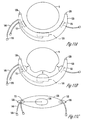
- FIG. 1 is a side cross sectional drawing of a female anatomy showing the bladder, urethra, vagina, and pubic bone in a patient with pelvic floor dysfunction and loss of support giving rise to urethral hypermobility, thus resulting in the displacement of the bladder.
- the abdominal pressure is increased momentarily.
- the result may be a shifting or "hypermobility" of the bladder near the region of the bladder neck, which results in unwanted urine leakage. This problem is reduced by adding lift and support to the area of the bladder near the bladder neck using a sling.
- FIG. 2 is a side cross sectional drawing of the female anatomy demonstrating a sling to lift and support the bladder and to diminish the curvature of the urethra and the bladder neck.
- the bladder is lifted in FIG. 2 , as compared to the bladder position in FIG. 1 .
- the urethra near the bladder neck is also supported by the sling and the tissue near the vagina is no longer compressed by the bladder.
- Attachment of the sling may be made using bone anchoring or suturing to the pubic bone, by attachment to strong ligaments of the female anatomy, such as the Cooper's ligaments, or by attachment to the rectus abdominous muscle.
- strong ligaments of the female anatomy such as the Cooper's ligaments
- a variety of attachment apparatus and methods are provided in the present description.
- FIG. 3 shows a top cross sectional drawing of the female anatomy from a view where the urethra 8 is normal to the plane of the drawing and showing a cross section of an adjustable sling with an expandable element 10 in the sling cup.
- the expandable element 10 is supported by the attachment straps 14 and is positioned between the vagina 7 and the urethra 8 in the region of the bladder neck. Tightening the attachment straps 14 provides a support of the urethra 8 and bladder neck due to forces on the attachment straps 14 and the expandable element 10. The position of the urethra 8 with respect to the pubic bone is adjusted during surgery by controlling the tension on the attachment straps 14, which are connected to the anchors 13.
- the expandable element 10 is made of any biocompatible material which is suitable for implantation and has the requisite mechanical properties for strength, elasticity, and durability. Some suitable materials include silicone and polyurethane.
- the element is connected to a conduit 11 which terminates in a port, such as a septum 12.
- the septum 12 is made of a self sealing material which serves as a port for a source of flowable material for adjusting the size of the expandable element and which self seals upon removal of the source of flowable material.
- the self-sealing material is silicone in one configuration, however, other materials may be used.
- the flowable material used may be a saline solution. Other flowable materials may be used, including, but not limited to x-ray contrast-media, and/or hydrophilic particle suspensions. Combinations of flowable materials may be used.
- Fluid communication between the septum 12, conduit 11, and expandable element 10 is such that the expandable element may be expanded by adding a flowable material using a source accessing the port (septum 12) or contracted by withdrawing flowable material from the source accessing the port (septum 12). Adding or withdrawing is an adjustment to the size of the expandable element which is performed postoperatively, and may be performed using a syringe 15 containing a flowable material.
- Adjustment of the expandable element is facilitated by positioning the septum under the skin and in a region convenient for access by a syringe, such as the labia majora or mons pubis. Other locations and methods for positioning may be used.
- conduit 11 is long enough for positioning the septum in a desirable location and tunneling through the tissue back towards the anterior surface of the pubis.
- This postoperative adjustment may be made by locating the septum near its expected location and using the syringe 15 to add or withdraw flowable material, adjusting the position of the urethra 8 and the coaptation of the urethra 8 near the bladder neck.
- FIG. 3 shows anchoring to the pubic bone 16
- other anchoring points such as the Cooper's ligaments
- the straps 14 are anchored to the pubic bone 16 using bone anchors, sutures, or glue. Other attachments may be used.
- the attachment straps may be made of nylon. In other embodiments, stainless steel or polypropylene are used. Attachment of the straps 14 to the expandable element may be accomplished by use of surgical needles.
- the expandable element changes in size when flowable material is added or withdrawn.
- the expandable element varies in size between approximately 8-15 mm in thickness. Other ranges may be used.
- the expandable element may change in volume in various ranges. In one configuration a range of 2-20 cc's is used. Other ranges may be employed.
- FIG. 4 shows a top view of the adjustable sling shown in FIG. 3 .
- the figure is not necessarily drawn to scale and the size of the expandable element and straps may vary without departing from the present invention.
- FIG. 5 shows a top cross sectional drawing of the female anatomy from a view where the urethra is normal to the plane of the drawing and showing a cross section of an adjustable sling.
- strap 54 is modified to include an adjustable element 50 for adjusting the tension in strap 54 and for changing the displacement of the urethra 8, accordingly. Adjustment of element 50 is performed by adding or subtracting flowable material to element 50 using septum 52 in fluid communication with conduit 51.
- element 50 is a bellows with a length that is a function of the flowable material added to the bellows. This provides an adjustment of the lift or support of the bladder near the bladder neck in this configuration.
- element 50 may be located on different portions of strap 54 in some configurations. Other configurations include the use of element 50 on both strap 54 and strap 55. Another configuration includes the use of multiple elements 50 to provide additional displacement of urethra 8.
- sling 56 is not adjustable. In some configurations, sling 56 is a conventional sling. In some configurations, sling 56 is adjustable, including any of the configurations provided in this specification.
- FIG. 6 shows a top cross sectional drawing of the female anatomy from a view where the urethra is normal to the plane of the drawing and showing a cross section of an adjustable sling according to another configuration.
- an adjustable anchor 63 is incorporated into a single connection point for straps 64.
- Sling 66 is connected to the straps 64.
- the tension on sling 66 is adjustable by changing settings at adjustable anchor 63.
- FIG. 7 shows one example of a process for adjusting both the lift and support of the bladder/bladder neck and the coaptation of the urethra near the bladder neck.
- an adjustable mount for the sling and an expandable element are used to provide adjustment of the lift and support and to provide adjustment of the coaptation of the urethra.
- the adjustable sling is implanted and the lift and support provided by the sling is initially adjusted.
- the expandable element is only partially filled. After implantation, the urethral function is measured.
- the lift and support of the sling is adjusted first and then the coaptation is adjusted by filling or withdrawing flowable material from the expandable element.
- FIG. 8A is a cross sectional view of an adjustable sling cup to demonstrate an uninflated state.
- sling cup 120 contains an integrated conduit portion 141 which provides an interface for fluid communication between balloon 110 and conduit 140 which terminates in port 150.
- Port 150 may be a self sealing septum.
- Attachment tabs 130 may be connected to straps (not shown) by suture, or tabs 130 may contain a perforation so that straps may be tied to each tab 130.
- the sling is secured using any of the connection systems and methods described in this specification, including all of the adjustable apparatus and methods taught herein.
- the sling cup 120 When properly tensioned, the sling cup 120 provides support and lift to the bladder neck distributed across face 140 (shown in FIG. 8C ). Coaptation of the urethra near the bladder neck is further adjustable using balloon 110 which is inflated to provide force on urethra 8 to assist in providing adequate coaptation for alleviating type III urinary stress incontinence. Port 150 is located at a position which is easy to access by a source of flowable material, such as a syringe. Using this example, urethral coaptation is substantially independently adjustable of the lift and support of the bladder by cup 120.
- FIG. 8B is a cross sectional view of the adjustable sling of FIG. 8A demonstrating one inflated state.
- the coaptation of urethra 8 is adjustable after the implantation of device to provide enhanced coaptation without requiring another surgery.
- the drawing of the balloon 110 is not necessarily to scale, and the location, size, and maximum size of the balloon 110 may differ.
- different shaped balloons may be employed and other variations may be used, such as balloons which expand to a predetermined shape.
- Cup 120 is made of any biocompatible material, and may be flexible for ease of implantation. Implantation of such device may be performed through a vaginal incision method. Alternatively, cup 120 may be semi-rigid to accommodate the integrated conduit portion 141.
- FIG. 8C is a top view of the adjustable sling of FIG. 8A .
- the size, shape and position of balloon 110 with respect to surface 140 may change.
- FIG. 9A is a top view of the adjustable sling cup according to an embodiment of the present invention.
- multiple balloons 110a and 110b are used to better control the coaptivity of the urethral portion near the bladder.
- Multiple ports 150a and 150b are also used to independently control the expansion of each balloon.
- a septum having dual ports is used to provide fluid communication to the plurality of balloons, as is shown in FIG. 12 .
- FIG. 9B and FIG. 9C show a side cross sectional drawing of the female anatomy demonstrating the adjustable sling cup of FIG. 9A to lift and support the bladder with respect to the pubic bone and to diminish the curvature of the urethra at the bladder neck, the adjustable sling also providing adjustable urethral coaptation.
- This figure shows the mechanical forces on the bladder neck portion of the urethra due to the sling straps and due to the effect of the balloons 110a and 110b on the urethra.
- the inflation of the balloons is independently adjustable to provide the proper amount of coaptation.
- FIG. 10A is a cross sectional view of an adjustable sling according to another embodiment of the present invention to demonstrate an uninflated state.
- all of the balloons are connected to the same conduit, however, other connections may be made without departing from the present system.
- the additional balloons 111 and 112 provide additional coaptation control by applying force from a plurality of directions.
- balloons 111 and 112 are connected to a first common conduit and a first port, and balloon 110 is connected to a separate, second conduit and a separate, second port. This allows balloons 111 and 112 to fill evenly and independently of balloon 110.
- FIG. 10B is a cross sectional view of the adjustable sling of FIG. 10A demonstrating one inflated state.
- Sling cup 120 has a surface 140 ( FIG. 10C ) which provides the lift and support of the bladder when properly connected to straps (not shown) at tabs 130.
- the additional coaptive forces on the urethra 8 due to the inflation are shown with arrows.
- FIG. 10C is a top view of the adjustable sling of FIG. 10A according to one embodiment of the present system.
- the shapes, placement, and sizes of the balloons may change without departing from the present system.
- FIG. 11A is a cross sectional view of an adjustable sling according to one embodiment of the present system to demonstrate an uninflated state.
- a plurality of ports and independent conduits are used to independently fill each balloon.
- a septum having a plurality of ports may be used to have a common position where each balloon may be filled, as is shown in FIG. 12 . Additional ports may be added to the structure of FIG. 12 .
- FIG. 11B is a cross sectional view of the adjustable sling of FIG. 11A demonstrating one inflated state.
- Sling cup 120 has a surface 140 ( FIG. 10C ) which provides the lift and support of the bladder when properly connected to straps (not shown) at tabs 130.
- the additional coaptive forces on the urethra 8 due to the inflation are shown with arrows.
- FIG. 11C is a top view of the adjustable sling of FIG. 11A according to one embodiment of the present system.
- the shapes, placement, and sizes of the balloons may change without departing from the present system.
Abstract
Description
- The present invention relates generally to treatment of urinary stress incontinence and in particular to an apparatus for treatment of stress urinary incontinence using an adjustable sling.
- Urinary stress incontinence arises when an increase in abdominal pressure, such as from laughing, coughing, lifting, or exercise, results in urinary leakage. Normally, the urethra, which is the urinary lumen which passes urine from the bladder, will not leak with ordinary increases in abdominal pressure, also referred to as stress. However there are two conditions, referred to as type II and type III that commonly lead to incontinence.
- Type II incontinence, also referred to as hypermobility, occurs when the support structures of the pelvic floor have been weakened, for instance from childbirth. This allows the bladder to descend below its normal location in the abdominal cavity and the bladder neck, where it joins the urethra, to funnel open under increased abdominal pressure.
- Type II incontinence has most often been treated by a class of surgical procedures called suspensions of which there are many variations. Variations such as the Marshal-Marchetti-Krantz or the Burch procedures are quite invasive, requiring an abdominal incision. Other variations, generally called needle suspensions and including the Stamey and Raz procedures, are less invasive and may be done on an outpatient basis. Generally these procedures place sutures into tissue on either side of the urethra near the bladder neck and then lift or suspend the urethra and bladder from a higher anchoring point such the pubic bone, coopers ligament or the rectus abdominis muscle. This support compensates for weakness of the pelvic floor.
- Unfortunately it has been found that these procedures, especially the needle suspensions, often fail over time because the sutures pull through the tissue on either side of the bladder neck or the tissue continues to sag between these points. Another concern is that if the bladder neck is lifted too high the patient may be put into urinary obstruction. Still another concern is that too much elevation may induce urge incontinence where the patient feels a need to urinate even when the bladder is not full. These later conditions may not be detected until after the surgery and the patient is up and around. In order to address some of these problems patents
US-A-4,938,760 andUS-A-4,969,892 propose a mechanism for allowing postoperative adjustment to the degree of suspension. - The document
EP-A-0 639 355 discloses a prosthesis for controlling urinary incontinence in women by correcting the vesico-urethral angle with a fluid-filled or fluid-fillable, height-adjustable elevation chamber which can be inserted as an adjustable spacer between the vagina and the start of the urethra and whose distance-determining height can be adjusted in the implanted state by puncturing and correction of the fluid amount. The described prosthesis comprises the technical features of the preamble of theindependent claim 1. - The other common cause of stress incontinence, type III also called intrinsic sphincter deficiency, occurs when the urinary sphincter which controls flow of urine from the bladder is dysfunctional. This may be caused by trauma, urethral scarring or any of a number of neurological conditions. For type III incontinence the most common treatment has been a class of surgical procedures called slings.
- Generally a sling or strap of material is placed between the urethra and vagina and the ends are attached to the same selection of higher anchoring points as for a suspension procedure. Pressure of the sling on the underside of the urethra causes closing or coaptation of the urethra to compensate for the dysfunctional sphincter. Another way to achieve coaptation would be to provide an expandable element or elements such as balloons on the sling underneath or alongside the urethra. The sling may be made from artificial material such as polypropylene mesh, autologous tissue harvested from the patient such as rectus fascia, or cadaveric fascia latta.
- While originally intended to provide coaptation for treating type III incontinence it has been recognized that slings also provide the support function sought by suspension procedures. While slings are somewhat more invasive than needle suspensions, they provide more reliable support since the sling is a continuous piece of material that goes underneath the urethra rather than being attached to fallible tissue alongside. At the same time it has also been recognized that mast stress incontinent patients do not have pure type II or type III but rather some of both. Often treating one of these conditions will unmask the presence of the other.
- For these reasons surgeons are more and more turning to slings to treat both types of stress incontinence. Nevertheless slings are still prone to some of the same problems as suspensions. Often it is not possible to tell if there has been enough coaptation or suspension to provide continence without urinary obstruction before the patient has recovered. Another problematic disorder which may result from the foregoing procedures is called "postsurgical urgency," which is caused by improperly applied pressure to the periurethral tissues in which innervation is very dense causing hyperactivity of the bladder and urethra. This disorder causes the patient to feel an urgency to void when their bladder does not require voiding.
Amelioration of the foregoing problems generally entails a second open surgical procedure to reduce the pressure on the bladder neck and proximal urethra.
Thus, there is a need in the art for an improved sling for the treatment of urinary stress incontinence. - The present invention provides an implantable adjustable sling for treatment of urinary stress incontinence, as defined in
claim 1. The sling is adjustable peri-operatively and post-operatively for treatment of different urinary stress incontinence types and provide adjustable urethral positioning and adjustable urethral coaptation. The present system provides for postoperative adjustment of sling tension using adjustable elements in the sling assembly. The present system also provides a number of demonstrative embodiments for an adjustable sling where positioning of the bladder is controlled using the adjustable sling and where coaptation of the urethra is controlled by postoperative inflation of one or more balloons mounted in a sling cup. - For adjusting the adjustable sling after surgical implantation, in one embodiment a self sealing septum is located near the skin for convenient filling using a syringe. Multiple port embodiments are also discussed.
-
-
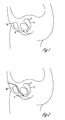
FIG. 1 is a side cross sectional drawing of a female anatomy showing the bladder, urethra, vagina, and pubic bone in a patient with pelvic floor dysfunction and loss of support giving rise to urethral hypermobility, thus resulting in the displacement of the bladder. -
FIG. 2 is a side cross sectional drawing of the female anatomy demonstrating a sling to lift and support the bladder with respect to the pubic bone and to diminish the curvature of the urethra and the bladder neck. -
FIG. 3 shows a top cross sectional drawing of the female anatomy from a view where the urethra is normal to the plane of the drawing and showing a comparative example of an adjustable sling with an expandable element. -
FIG. 4 shows a top view of the adjustable sling cup according to the example shown inFIG. 3 . -
FIG. 5 shows a top cross sectional drawing of the female anatomy from a view where the urethra is normal to the plane of the drawing and showing a cross section of an adjustable sling according to one embodiment of the present system. -
FIG. 6 shows a top cross sectional drawing of the female anatomy from a view where the urethra is normal to the plane of the drawing and showing a cross section of an adjustable sling according to one embodiment of the present system. -
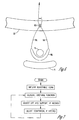
FIG. 7 is a flow chart showing one example of a procedure for adjusting one embodiment of the adjustable sling. -
FIG. 8A is a cross sectional view of an adjustable sling cup according to a comparative example to demonstrate an uninflated state. -
FIG. 8B is a cross sectional view of the adjustable sling cup ofFIG. 8A demonstrating one inflated state. -
FIG. 8C is a top view of the adjustable sling cup ofFIG. 8A . -
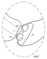
FIG. 9A is a top view of the adjustable sling according to one embodiment of the present system. -
FIG. 9B andFIG. 9C show a side cross sectional drawing of the female anatomy demonstrating the adjustable sling ofFIG. 9A to lift and support the bladder with respect to the pubic bone and to diminish the curvature of the urethra at the bladder neck, the adjustable sling also providing adjustable urethral coaptation. -
FIG. 10A is a cross sectional view of an adjustable sling cup according to one embodiment of the present system to demonstrate an uninflated state. -
FIG. 10B is a cross sectional view of the adjustable sling ofFIG. 10A demonstrating one inflated state. -
FIG. 10C is a top view of the adjustable sling cup ofFIG. 10A according to one embodiment of the present system. -
FIG. 11A is a cross sectional view of an adjustable sling cup according to one embodiment of the present system to demonstrate an uninflated state. -
FIG. 11B is a cross sectional view of the adjustable sling cup ofFIG. 11A demonstrating one inflated state. -
FIG. 11C is a top view of the adjustable sling cup ofFIG. 11A according to one embodiment of the present system -
FIG. 12 is a diagram of a one embodiment of a multiple port system. - This detailed description provides a number of different embodiments methods and apparatus related to the present system. The embodiments provided herein are not intended in an exclusive or limited sense, and variations may exist in organization, dimension, chemical composition, and mechanical design and configuration, without departing from the claimed invention, the scope of which is provided by the appended claims.
-
FIG. 1 is a side cross sectional drawing of a female anatomy showing the bladder, urethra, vagina, and pubic bone in a patient with pelvic floor dysfunction and loss of support giving rise to urethral hypermobility, thus resulting in the displacement of the bladder. When the patient is laughing, coughing, lifting, or exercising, the abdominal pressure is increased momentarily. For patients with type II stress incontinence, the result may be a shifting or "hypermobility" of the bladder near the region of the bladder neck, which results in unwanted urine leakage. This problem is reduced by adding lift and support to the area of the bladder near the bladder neck using a sling. -
FIG. 2 is a side cross sectional drawing of the female anatomy demonstrating a sling to lift and support the bladder and to diminish the curvature of the urethra and the bladder neck. The bladder is lifted inFIG. 2 , as compared to the bladder position inFIG. 1 . The urethra near the bladder neck is also supported by the sling and the tissue near the vagina is no longer compressed by the bladder. Attachment of the sling may be made using bone anchoring or suturing to the pubic bone, by attachment to strong ligaments of the female anatomy, such as the Cooper's ligaments, or by attachment to the rectus abdominous muscle. A variety of attachment apparatus and methods are provided in the present description. -
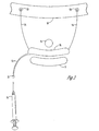
FIG. 3 shows a top cross sectional drawing of the female anatomy from a view where theurethra 8 is normal to the plane of the drawing and showing a cross section of an adjustable sling with anexpandable element 10 in the sling cup. - In this example the
expandable element 10 is supported by the attachment straps 14 and is positioned between thevagina 7 and theurethra 8 in the region of the bladder neck. Tightening the attachment straps 14 provides a support of theurethra 8 and bladder neck due to forces on the attachment straps 14 and theexpandable element 10. The position of theurethra 8 with respect to the pubic bone is adjusted during surgery by controlling the tension on the attachment straps 14, which are connected to theanchors 13. - The
expandable element 10 is made of any biocompatible material which is suitable for implantation and has the requisite mechanical properties for strength, elasticity, and durability. Some suitable materials include silicone and polyurethane. The element is connected to aconduit 11 which terminates in a port, such as aseptum 12. Theseptum 12 is made of a self sealing material which serves as a port for a source of flowable material for adjusting the size of the expandable element and which self seals upon removal of the source of flowable material. The self-sealing material is silicone in one configuration, however, other materials may be used. The flowable material used may be a saline solution. Other flowable materials may be used, including, but not limited to x-ray contrast-media, and/or hydrophilic particle suspensions. Combinations of flowable materials may be used. - Fluid communication between the
septum 12,conduit 11, andexpandable element 10 is such that the expandable element may be expanded by adding a flowable material using a source accessing the port (septum 12) or contracted by withdrawing flowable material from the source accessing the port (septum 12). Adding or withdrawing is an adjustment to the size of the expandable element which is performed postoperatively, and may be performed using asyringe 15 containing a flowable material. - Adjustment of the expandable element is facilitated by positioning the septum under the skin and in a region convenient for access by a syringe, such as the labia majora or mons pubis. Other locations and methods for positioning may be used. Thus,
conduit 11 is long enough for positioning the septum in a desirable location and tunneling through the tissue back towards the anterior surface of the pubis. This provides a system in which size of the expandable element is adjustable after the implantation of the device. Therefore, theurethra 8 may be displaced in either direction by adding or subtracting flowable material to the expandable element through the septum after surgery. This postoperative adjustment may be made by locating the septum near its expected location and using thesyringe 15 to add or withdraw flowable material, adjusting the position of theurethra 8 and the coaptation of theurethra 8 near the bladder neck. - Although
FIG. 3 shows anchoring to thepubic bone 16, other anchoring points, such as the Cooper's ligaments, may be used. Thestraps 14 are anchored to thepubic bone 16 using bone anchors, sutures, or glue. Other attachments may be used. The attachment straps may be made of nylon. In other embodiments, stainless steel or polypropylene are used. Attachment of thestraps 14 to the expandable element may be accomplished by use of surgical needles. - The expandable element changes in size when flowable material is added or withdrawn. In one configuration, the expandable element varies in size between approximately 8-15 mm in thickness. Other ranges may be used. The expandable element may change in volume in various ranges. In one configuration a range of 2-20 cc's is used. Other ranges may be employed.
-
FIG. 4 shows a top view of the adjustable sling shown inFIG. 3 . The figure is not necessarily drawn to scale and the size of the expandable element and straps may vary without departing from the present invention. -
FIG. 5 shows a top cross sectional drawing of the female anatomy from a view where the urethra is normal to the plane of the drawing and showing a cross section of an adjustable sling. - In this
configuration strap 54 is modified to include anadjustable element 50 for adjusting the tension instrap 54 and for changing the displacement of theurethra 8, accordingly. Adjustment ofelement 50 is performed by adding or subtracting flowable material toelement 50 usingseptum 52 in fluid communication withconduit 51. - In one
configuration element 50 is a bellows with a length that is a function of the flowable material added to the bellows. This provides an adjustment of the lift or support of the bladder near the bladder neck in this configuration. - It is understood that
element 50 may be located on different portions ofstrap 54 in some configurations. Other configurations include the use ofelement 50 on bothstrap 54 andstrap 55. Another configuration includes the use ofmultiple elements 50 to provide additional displacement ofurethra 8. In some configurations,sling 56 is not adjustable. In some configurations,sling 56 is a conventional sling. In some configurations,sling 56 is adjustable, including any of the configurations provided in this specification. -
FIG. 6 shows a top cross sectional drawing of the female anatomy from a view where the urethra is normal to the plane of the drawing and showing a cross section of an adjustable sling according to another configuration. In this configuration anadjustable anchor 63 is incorporated into a single connection point for straps 64.Sling 66 is connected to thestraps 64. The tension onsling 66 is adjustable by changing settings atadjustable anchor 63. -
FIG. 7 shows one example of a process for adjusting both the lift and support of the bladder/bladder neck and the coaptation of the urethra near the bladder neck. In this example, an adjustable mount for the sling and an expandable element are used to provide adjustment of the lift and support and to provide adjustment of the coaptation of the urethra. The adjustable sling is implanted and the lift and support provided by the sling is initially adjusted. The expandable element is only partially filled. After implantation, the urethral function is measured. The lift and support of the sling is adjusted first and then the coaptation is adjusted by filling or withdrawing flowable material from the expandable element. - One example of an adjustable sling cup is demonstrated in
FIG. 8. FIG. 8A is a cross sectional view of an adjustable sling cup to demonstrate an uninflated state. In this embodiment,sling cup 120 contains anintegrated conduit portion 141 which provides an interface for fluid communication betweenballoon 110 andconduit 140 which terminates inport 150.Port 150 may be a self sealing septum.Attachment tabs 130 may be connected to straps (not shown) by suture, ortabs 130 may contain a perforation so that straps may be tied to eachtab 130. The sling is secured using any of the connection systems and methods described in this specification, including all of the adjustable apparatus and methods taught herein. - When properly tensioned, the
sling cup 120 provides support and lift to the bladder neck distributed across face 140 (shown inFIG. 8C ). Coaptation of the urethra near the bladder neck is further adjustable usingballoon 110 which is inflated to provide force onurethra 8 to assist in providing adequate coaptation for alleviating type III urinary stress incontinence.Port 150 is located at a position which is easy to access by a source of flowable material, such as a syringe. Using this example, urethral coaptation is substantially independently adjustable of the lift and support of the bladder bycup 120.FIG. 8B is a cross sectional view of the adjustable sling ofFIG. 8A demonstrating one inflated state. In one embodiment, the coaptation ofurethra 8 is adjustable after the implantation of device to provide enhanced coaptation without requiring another surgery. - The drawing of the
balloon 110 is not necessarily to scale, and the location, size, and maximum size of theballoon 110 may differ. For example, different shaped balloons may be employed and other variations may be used, such as balloons which expand to a predetermined shape. -
Cup 120 is made of any biocompatible material, and may be flexible for ease of implantation. Implantation of such device may be performed through a vaginal incision method. Alternatively,cup 120 may be semi-rigid to accommodate theintegrated conduit portion 141. -
FIG. 8C is a top view of the adjustable sling ofFIG. 8A . The size, shape and position ofballoon 110 with respect tosurface 140 may change. -
FIG. 9A is a top view of the adjustable sling cup according to an embodiment of the present invention. In this embodiment, multiple balloons 110a and 110b are used to better control the coaptivity of the urethral portion near the bladder. Multiple ports 150a and 150b are also used to independently control the expansion of each balloon. In one embodiment a septum having dual ports is used to provide fluid communication to the plurality of balloons, as is shown inFIG. 12 . -
FIG. 9B andFIG. 9C show a side cross sectional drawing of the female anatomy demonstrating the adjustable sling cup ofFIG. 9A to lift and support the bladder with respect to the pubic bone and to diminish the curvature of the urethra at the bladder neck, the adjustable sling also providing adjustable urethral coaptation. This figure shows the mechanical forces on the bladder neck portion of the urethra due to the sling straps and due to the effect of the balloons 110a and 110b on the urethra. In one embodiment, the inflation of the balloons is independently adjustable to provide the proper amount of coaptation. -
FIG. 10A is a cross sectional view of an adjustable sling according to another embodiment of the present invention to demonstrate an uninflated state. In this embodiment all of the balloons are connected to the same conduit, however, other connections may be made without departing from the present system. Theadditional balloons balloon 110 is connected to a separate, second conduit and a separate, second port. This allows balloons 111 and 112 to fill evenly and independently ofballoon 110. -
FIG. 10B is a cross sectional view of the adjustable sling ofFIG. 10A demonstrating one inflated state.Sling cup 120 has a surface 140 (FIG. 10C ) which provides the lift and support of the bladder when properly connected to straps (not shown) attabs 130. The additional coaptive forces on theurethra 8 due to the inflation are shown with arrows. -
FIG. 10C is a top view of the adjustable sling ofFIG. 10A according to one embodiment of the present system. The shapes, placement, and sizes of the balloons may change without departing from the present system. -
FIG. 11A is a cross sectional view of an adjustable sling according to one embodiment of the present system to demonstrate an uninflated state. In this embodiment, a plurality of ports and independent conduits are used to independently fill each balloon. However, it is noted that it may be advantageous in other embodiments to connect conduits toballoons FIG. 12 . Additional ports may be added to the structure ofFIG. 12 . -
FIG. 11B is a cross sectional view of the adjustable sling ofFIG. 11A demonstrating one inflated state.Sling cup 120 has a surface 140 (FIG. 10C ) which provides the lift and support of the bladder when properly connected to straps (not shown) attabs 130. The additional coaptive forces on theurethra 8 due to the inflation are shown with arrows. -
FIG. 11C is a top view of the adjustable sling ofFIG. 11A according to one embodiment of the present system. The shapes, placement, and sizes of the balloons may change without departing from the present system. - Upon reading and understanding the present description, those skilled in the art would recognize that minor variations in the apparatus, processes, and applications described herein may exist without departing from the claimed invention, the scope of which being provided by the appended claims. The embodiments described herein are intended to demonstrate the present invention, and are not intended in an exclusive or limited sense. For example, a change in the positioning of adjustable elements, filling fluids, shapes, conduit layout and connectivity, and filling systems may occur. Furthermore, the shapes, placement, and sizes of the balloons may change.
Claims (12)
- An implantable device for treatment of stress incontinence, comprising:a first strap;a second strap; anda sling cup (120);wherein the first and second straps each have a first end connected to the sling cup, and a second end adapted to be anchored within a body,
characterised in that the sling cup (120) comprises a plurality of balloons (110A, 110B, 110, 111, 112) connected to one or more conduits, each conduit including a port (150), the plurality of balloons (110A, 110B, 110, 111, 112) adapted to be expanded by adding flowable material or contracted by withdrawal of flowable material via the port. - An implantable device according to claim 1, wherein the plurality of balloons (110, 111, 112) are connected to a single conduit (140).
- An implantable device according to claim 2, wherein each balloon of the plurality of balloons (110, 111, 112) is connected to a respective conduit (140).
- An implantable device according to any of claims 1 to 3, wherein the first strap (54) includes an adjustable element (50).
- An implantable device according to claim 4, wherein the first strap comprises a plurality of adjustable elements.
- An implantable device according to claim 4 or claim 5, wherein the second strap comprises an adjustable element.
- An implantable device according to claim 4 or claim 5, wherein at least one adjustable element includes a hydraulic bellows.
- An implantable device according to any according to claims 1 to 7, wherein at least one port (150) includes a self sealing port.
- An implantable device according to claim 8, wherein at least one port includes a septum.
- The implantable device according to any according to claims 1 to 9, further comprising an anchoring system (13, 63) for anchoring the first and second straps.
- An implantable device according to any one of claims 4 to 6, wherein at least one adjustable element includes a conduit (51) and a port (52).
- An implantable device according to any according to claims 1 to 10, comprising a self sealing port adapted to connect to a plurality of conduits.
Applications Claiming Priority (3)
| Application Number | Priority Date | Filing Date | Title |
|---|---|---|---|
| US13191599P | 1999-04-30 | 1999-04-30 | |
| US131915P | 1999-04-30 | ||
| PCT/US2000/011707 WO2000066030A1 (en) | 1999-04-30 | 2000-04-28 | Method and apparatus for adjustable sling for treatment of urinary stress incontinence |
Publications (2)
| Publication Number | Publication Date |
|---|---|
| EP1189552A1 EP1189552A1 (en) | 2002-03-27 |
| EP1189552B1 true EP1189552B1 (en) | 2009-04-01 |
Family
ID=22451587
Family Applications (1)
| Application Number | Title | Priority Date | Filing Date |
|---|---|---|---|
| EP00928640A Expired - Lifetime EP1189552B1 (en) | 1999-04-30 | 2000-04-28 | Apparatus with an adjustable sling for treatment of urinary stress incontinence |
Country Status (6)
| Country | Link |
|---|---|
| US (2) | US7395822B1 (en) |
| EP (1) | EP1189552B1 (en) |
| AT (1) | ATE427074T1 (en) |
| AU (1) | AU4684500A (en) |
| DE (1) | DE60041917D1 (en) |
| WO (1) | WO2000066030A1 (en) |
Cited By (3)
| Publication number | Priority date | Publication date | Assignee | Title |
|---|---|---|---|---|
| US9351824B2 (en) | 2012-11-14 | 2016-05-31 | ImplantADJUST, LLC | Adjustable implant with self-sealing elastomeric membrane and methods of fabrication thereof |
| US9402705B2 (en) | 2007-07-30 | 2016-08-02 | Boston Scientific Scimed, Inc. | Apparatus and method for the treatment of stress urinary incontinence |
| US10820984B2 (en) | 2012-11-14 | 2020-11-03 | ImplantADJUST, LLC | Implant with elastomeric membrane and methods of fabrication thereof |
Families Citing this family (92)
| Publication number | Priority date | Publication date | Assignee | Title |
|---|---|---|---|---|
| US6579224B1 (en) | 1999-10-11 | 2003-06-17 | Uromedica, Inc. | Apparatus and method for inserting an adjustable implantable genitourinary device |
| US6419624B1 (en) * | 1999-10-11 | 2002-07-16 | Uromedica, Inc. | Apparatus and method for inserting an adjustable implantable genitourinary device |
| US7364540B1 (en) * | 1997-06-12 | 2008-04-29 | Uromedica, Inc. | Implantable device and method for adjustably restricting a body lumen |
| US7395822B1 (en) | 1999-04-30 | 2008-07-08 | Uromedica, Inc. | Method and apparatus for adjustable sling for treatment of urinary stress incontinence |
| US6482145B1 (en) | 2000-02-14 | 2002-11-19 | Obtech Medical Ag | Hydraulic anal incontinence treatment |
| US6464628B1 (en) | 1999-08-12 | 2002-10-15 | Obtech Medical Ag | Mechanical anal incontinence |
| US6471635B1 (en) | 2000-02-10 | 2002-10-29 | Obtech Medical Ag | Anal incontinence disease treatment with controlled wireless energy supply |
| US6503189B1 (en) | 1999-08-12 | 2003-01-07 | Obtech Medical Ag | Controlled anal incontinence disease treatment |
| CN1202784C (en) | 2000-02-10 | 2005-05-25 | 波滕西亚医疗公司 | Controlled urinary incontinence treatment |
| CA2398496C (en) * | 2000-02-10 | 2009-05-19 | Surgical Development Ag | Urinary incontinence treatment with wireless energy supply |
| DE60135257D1 (en) | 2000-02-10 | 2008-09-18 | Potencia Medical Ag | Mechanical device for impotence treatment |
| CN1400888A (en) | 2000-02-11 | 2003-03-05 | 波滕西亚医疗公司 | Impotence treatment apparatus with energy transforming means |
| US20030100929A1 (en) | 2000-02-14 | 2003-05-29 | Peter Forsell | Controlled penile prosthesis |
| ATE296071T1 (en) | 2000-02-14 | 2005-06-15 | Potencia Medical Ag | PENIS PROSTHESIS |
| WO2001047440A2 (en) | 2000-02-14 | 2001-07-05 | Potencia Medical Ag | Male impotence prosthesis apparatus with wireless energy supply |
| FR2811218B1 (en) | 2000-07-05 | 2003-02-28 | Patrice Suslian | IMPLANTABLE DEVICE FOR CORRECTING URINARY INCONTINENCE |
| US8167785B2 (en) | 2000-10-12 | 2012-05-01 | Coloplast A/S | Urethral support system |
| US20060205995A1 (en) * | 2000-10-12 | 2006-09-14 | Gyne Ideas Limited | Apparatus and method for treating female urinary incontinence |
| GB0025068D0 (en) | 2000-10-12 | 2000-11-29 | Browning Healthcare Ltd | Apparatus and method for treating female urinary incontinence |
| US7235043B2 (en) | 2001-03-09 | 2007-06-26 | Boston Scientific Scimed Inc. | System for implanting an implant and method thereof |
| GB0108088D0 (en) | 2001-03-30 | 2001-05-23 | Browning Healthcare Ltd | Surgical implant |
| FR2838629B1 (en) * | 2002-04-17 | 2005-02-04 | Ct Hospitalier Universitaire Rouen | DEVICE FOR TREATING URINARY INCONTINENCE |
| EP1501444B1 (en) | 2002-04-30 | 2014-05-07 | Cook Medical Technologies LLC | Sling for supporting tissue |
| AU2003269934A1 (en) | 2002-08-02 | 2004-02-23 | C.R. Bard, Inc. | Self anchoring sling and introducer system |
| US7371245B2 (en) | 2002-08-02 | 2008-05-13 | C R Bard, Inc | Transobturator introducer system for sling suspension system |
| GB0307082D0 (en) | 2003-03-27 | 2003-04-30 | Gyne Ideas Ltd | Drug delivery device and method |
| US20100261951A1 (en) * | 2004-02-23 | 2010-10-14 | Uromedica, Inc. | Method and apparatus for an adjustable implantable continence device |
| GB0411360D0 (en) * | 2004-05-21 | 2004-06-23 | Mpathy Medical Devices Ltd | Implant |
| DE102004027458A1 (en) * | 2004-06-04 | 2006-01-19 | Fink, Thomas, Dr. | Suburethral adjustable transobturatory satin port system for treating female urinary incontinence, has polypropylene tape made of synthetic thread, and applied on set cushion such that seam above cushion is located centrical under urethra |
| WO2006091786A1 (en) * | 2005-02-23 | 2006-08-31 | Uromedica, Inc. | Method and apparatus for an adjustable implantable continence device |
| DE102005021893A1 (en) * | 2005-05-04 | 2006-11-09 | Aesculap Ag & Co. Kg | Device for the prevention of urinary incontinence in humans |
| DE102005021881A1 (en) | 2005-05-04 | 2006-11-09 | Aesculap Ag & Co. Kg | urinary incontinence band |
| EP1912590A1 (en) | 2005-07-26 | 2008-04-23 | AMS Research Corporation | Methods and systems for treatment of prolapse |
| US7699769B2 (en) * | 2005-09-01 | 2010-04-20 | Boston Scientific Scimed, Inc. | Adjustable surgical sling |
| WO2007059199A2 (en) | 2005-11-14 | 2007-05-24 | C.R. Bard, Inc. | Sling anchor system |
| WO2007137226A2 (en) | 2006-05-19 | 2007-11-29 | Ams Research Corporation | Method and articles for treatment of stress urinary incontinence |
| WO2007149348A2 (en) | 2006-06-16 | 2007-12-27 | Ams Research Corporation | Surgical implants and tools for treating pelvic conditions |
| EP2049039A2 (en) | 2006-06-22 | 2009-04-22 | AMS Research Corporation | Adjustable tension incontinence sling assemblies |
| US8684907B2 (en) * | 2007-02-26 | 2014-04-01 | Jay S. Hortenstine | Adjustable incontinence apparatus |
| US9113989B2 (en) * | 2007-08-14 | 2015-08-25 | The Board Of Trustees Of The Leland Stanford Junior University | Methods and devices for supporting, elevating, or compressing internal structures |
| EP3964243A1 (en) | 2008-01-28 | 2022-03-09 | Implantica Patent Ltd | Blood clot removal device, system, and method |
| BRPI0906746A8 (en) | 2008-01-29 | 2019-05-14 | Implantica Patent Ltd | apparatus for treating gastresophageal reflux disease |
| US9017243B2 (en) | 2008-08-25 | 2015-04-28 | Ams Research Corporation | Minimally invasive implant and method |
| KR101739304B1 (en) | 2008-08-25 | 2017-05-24 | 에이엠에스 리서치 코포레이션 | Minimally invasive implant system |
| MX2011002265A (en) * | 2008-08-30 | 2011-04-07 | Bihler Of America Inc | Urethral slings, and methods for the implantation and adjustment thereof. |
| US9072907B2 (en) | 2008-10-10 | 2015-07-07 | Peter Forsell | Heart help device, system, and method |
| US11628053B2 (en) * | 2008-10-10 | 2023-04-18 | Peter Forsell | Variable sling for urinary continence |
| US11123171B2 (en) | 2008-10-10 | 2021-09-21 | Peter Forsell | Fastening means for implantable medical control assembly |
| ES2950024T3 (en) | 2008-10-10 | 2023-10-04 | Medicaltree Patent Ltd | Heart support device, system and procedure |
| EP2349096B1 (en) | 2008-10-10 | 2021-01-27 | MedicalTree Patent Ltd. | An improved artificial valve |
| EP2349170B1 (en) | 2008-10-10 | 2023-09-27 | Implantica Patent Ltd. | Apparatus for the treatment of female sexual dysfunction |
| US8874215B2 (en) | 2008-10-10 | 2014-10-28 | Peter Forsell | System, an apparatus, and a method for treating a sexual dysfunctional female patient |
| EP2391277B1 (en) | 2008-12-30 | 2016-04-20 | Cook Medical Technologies LLC | Magnetic retraction device |
| DK200900718A (en) | 2009-06-08 | 2010-12-09 | Coloplast As | Anatomical augmentation device |
| US9949812B2 (en) | 2009-07-17 | 2018-04-24 | Peter Forsell | Vaginal operation method for the treatment of anal incontinence in women |
| US10952836B2 (en) | 2009-07-17 | 2021-03-23 | Peter Forsell | Vaginal operation method for the treatment of urinary incontinence in women |
| WO2011082287A1 (en) | 2009-12-30 | 2011-07-07 | Ams Research Corporation | Implant systems with tensioning feedback |
| EP2579809B1 (en) | 2010-06-08 | 2020-11-25 | Regents of the University of Minnesota | Vascular elastance |
| US8550979B2 (en) | 2010-06-15 | 2013-10-08 | Coloplast A/S | Method of treating incontinence |
| US10028813B2 (en) | 2010-07-22 | 2018-07-24 | Boston Scientific Scimed, Inc. | Coated pelvic implant device and method |
| US8784296B2 (en) | 2010-09-07 | 2014-07-22 | Coloplast A/S | Angled surgical introducer |
| JP5782523B2 (en) | 2010-11-22 | 2015-09-24 | アリア シーブイ, インコーポレイテッド | System and method for reducing pulsating pressure |
| US9572648B2 (en) | 2010-12-21 | 2017-02-21 | Justin M. Crank | Implantable slings and anchor systems |
| US9622848B2 (en) | 2011-02-23 | 2017-04-18 | Boston Scientific Scimed, Inc. | Urethral stent system and method |
| US9125717B2 (en) * | 2011-02-23 | 2015-09-08 | Ams Research Corporation | Implant tension adjustment system and method |
| US8808162B2 (en) | 2011-03-28 | 2014-08-19 | Ams Research Corporation | Implants, tools, and methods for treatment of pelvic conditions |
| US9089393B2 (en) | 2011-03-28 | 2015-07-28 | Ams Research Corporation | Implants, tools, and methods for treatment of pelvic conditions |
| US9492259B2 (en) | 2011-03-30 | 2016-11-15 | Astora Women's Health, Llc | Expandable implant system |
| US9782245B2 (en) | 2011-03-30 | 2017-10-10 | James R. Mujwid | Implants, tools, and methods for treatment of pelvic conditions |
| US10058240B2 (en) | 2011-06-29 | 2018-08-28 | Boston Scientific Scimed, Inc. | Systems, implants, tools, and methods for treatments of pelvic conditions |
| US20130006049A1 (en) | 2011-06-30 | 2013-01-03 | Alexander James A | Implants, tools, and methods for treatments of pelvic conditions |
| US9351723B2 (en) | 2011-06-30 | 2016-05-31 | Astora Women's Health, Llc | Implants, tools, and methods for treatments of pelvic conditions |
| US9414903B2 (en) | 2011-07-22 | 2016-08-16 | Astora Women's Health, Llc | Pelvic implant system and method |
| EP2734148B1 (en) | 2011-07-22 | 2019-06-05 | Boston Scientific Scimed, Inc. | Pelvic implant system |
| US9492191B2 (en) | 2011-08-04 | 2016-11-15 | Astora Women's Health, Llc | Tools and methods for treatment of pelvic conditions |
| US20130035555A1 (en) | 2011-08-05 | 2013-02-07 | Alexander James A | Systems, implants, tools, and methods for treatment of pelvic conditions |
| US10098721B2 (en) | 2011-09-01 | 2018-10-16 | Boston Scientific Scimed, Inc. | Pelvic implant needle system and method |
| USD721807S1 (en) | 2011-09-08 | 2015-01-27 | Ams Research Corporation | Surgical indicators |
| USD721175S1 (en) | 2011-09-08 | 2015-01-13 | Ams Research Corporation | Backers for surgical indicators |
| USD736382S1 (en) | 2011-09-08 | 2015-08-11 | Ams Research Corporation | Surgical indicator with backers |
| WO2014091476A1 (en) * | 2012-12-11 | 2014-06-19 | Innoventions Ltd | Medical sling |
| AU2014296053B2 (en) | 2013-08-01 | 2018-09-06 | Cook Biotech Incorporated | Tissue adjustment implant |
| US9421017B2 (en) | 2014-01-15 | 2016-08-23 | Jacques Seguin | Methods and apparatus using branched balloon for treating pulmonary arterial hypertension |
| FR3017044A1 (en) * | 2014-01-31 | 2015-08-07 | Jacques Seguin | DEVICE FOR TREATING PULMONARY ARTERIAL HYPERTENSION |
| US9427236B2 (en) | 2014-01-31 | 2016-08-30 | Jacques Seguin | Methods and apparatus using an anchored balloon for treating pulmonary arterial hypertension |
| US8876850B1 (en) | 2014-06-19 | 2014-11-04 | Aria Cv, Inc. | Systems and methods for treating pulmonary hypertension |
| EP3267939A4 (en) * | 2015-03-13 | 2018-10-31 | University Hospitals Case Medical Center | Surgical probe calibration system and method |
| US11331105B2 (en) | 2016-10-19 | 2022-05-17 | Aria Cv, Inc. | Diffusion resistant implantable devices for reducing pulsatile pressure |
| WO2019058180A2 (en) * | 2017-09-25 | 2019-03-28 | Marian Devonec | Readjustable and reversible tensioning means for urinary incontinence |
| US11510766B2 (en) | 2019-02-14 | 2022-11-29 | Uromedica, Inc. | Method and apparatus for monitoring implantable device for urinary continence |
| WO2021046252A1 (en) | 2019-09-06 | 2021-03-11 | Aria Cv, Inc. | Diffusion and infusion resistant implantable devices for reducing pulsatile pressure |
| CN112022423B (en) * | 2020-09-03 | 2024-03-08 | 温州医科大学附属第一医院 | Urinary incontinence sling evaluation system and image evaluation method |
Citations (2)
| Publication number | Priority date | Publication date | Assignee | Title |
|---|---|---|---|---|
| EP0639355A1 (en) * | 1993-08-21 | 1995-02-22 | RULL, Johann, Dr. med. | Prosthesis for controlling urinary incontinence in women |
| WO1998035632A1 (en) * | 1997-02-13 | 1998-08-20 | Boston Scientific Ireland Limited | Stabilization sling for use in minimally invasive pelvic surgery |
Family Cites Families (86)
| Publication number | Priority date | Publication date | Assignee | Title |
|---|---|---|---|---|
| US3138161A (en) | 1963-02-25 | 1964-06-23 | Latex Ind Inc | Needle plug guide for catheter |
| US4019499A (en) | 1976-04-22 | 1977-04-26 | Heyer-Schulte Corporation | Compression implant for urinary incontinence |
| US4553959A (en) | 1982-01-27 | 1985-11-19 | The Victoria University Of Manchester | Urethral catheter |
| US4428365A (en) * | 1982-03-01 | 1984-01-31 | Hakky Said I | Anti-incontinent prostheses |
| US4784660A (en) | 1982-09-21 | 1988-11-15 | The Johns Hopkins University | Manually actuated hydraulic sphincter having a mechanical actuator |
| US4559043A (en) | 1984-10-29 | 1985-12-17 | Drs Infusion Systems, Inc. | Assembly with septum fitting for connecting adaptor and fluid tube |
| US4669478A (en) | 1985-03-21 | 1987-06-02 | Robertson Jack R | Device for diagnosing and relieving female incontinence |
| US4592339A (en) * | 1985-06-12 | 1986-06-03 | Mentor Corporation | Gastric banding device |
| US4634443A (en) * | 1985-07-05 | 1987-01-06 | Habley Medical Technology Corporation | Single circuit elastofluidic sphincter |
| US4909785A (en) | 1986-03-25 | 1990-03-20 | American Medical Systems, Inc. | Method for valving body fluids |
| GB8611129D0 (en) * | 1986-05-07 | 1986-06-11 | Annis D | Prosthetic materials |
| US4686962A (en) | 1986-07-03 | 1987-08-18 | Habley Medical Technology Corporation | Disposable cartridge assembly for hypodermically implanting a genitourinary prosthesis |
| US4832680A (en) | 1986-07-03 | 1989-05-23 | C.R. Bard, Inc. | Apparatus for hypodermically implanting a genitourinary prosthesis |
| US4773393A (en) | 1986-07-03 | 1988-09-27 | C. R. Bard, Inc. | Hypodermically implantable genitourinary prosthesis |
| US4802479A (en) | 1986-10-31 | 1989-02-07 | C. R. Bard, Inc. | Hand-held instrument for implanting, dispensing, and inflating an inflatable membrane |
| US4846784A (en) | 1987-07-01 | 1989-07-11 | C. R. Bard, Inc. | Manually adjustable sphincteric system |
| US5149052A (en) | 1987-11-16 | 1992-09-22 | Kingston Technologies, Inc. | Precision molding of polymers |
| US4817637A (en) | 1987-11-25 | 1989-04-04 | Medical Engineering Corporation | Subcutaneous injection and withdrawal site |
| US5012822A (en) | 1988-10-11 | 1991-05-07 | Schwarz Gerald R | Method for controlling urinary incontinence |
| US4969474A (en) | 1988-10-11 | 1990-11-13 | Schwarz Gerald R | Incontinence bladder control method and apparatus |
| US5123428A (en) | 1988-10-11 | 1992-06-23 | Schwarz Gerald R | Laparoscopically implanting bladder control apparatus |
| US5097848A (en) | 1988-10-11 | 1992-03-24 | Schwarz Gerald R | Incontinence bladder control method and apparatus |
| US5306226A (en) | 1989-02-09 | 1994-04-26 | Salama Fouad A | Urinary control with inflatable seal and method of using same |
| US4938760A (en) | 1989-03-29 | 1990-07-03 | American Medical Systems, Inc. | Female suspension procedure |
| DE3921120A1 (en) | 1989-06-28 | 1991-01-03 | Rull Johann Dr Med | PROSTHESIS FOR PREVENTING URINE CONTINENCE IN WOMEN |
| US5066303A (en) | 1989-08-07 | 1991-11-19 | Medical Engineering Corporation | Self-sealing tissue expander and method |
| US5133753A (en) | 1989-08-07 | 1992-07-28 | Medical Engineering Corporation | Method for expanding a self-sealing tissue prosthesis |
| US5041136A (en) * | 1989-10-27 | 1991-08-20 | General Electric Company | Implantable artificial soft bladder system |
| US5064434A (en) | 1990-04-04 | 1991-11-12 | Haber Terry M | Genitourinary implant |
| JP2514087Y2 (en) | 1990-05-25 | 1996-10-16 | 幸三 牧田 | Balloon with detachable double-sided check valve |
| US5041077A (en) * | 1990-10-26 | 1991-08-20 | George Kulick | Intravaginal incontinence prosthesis |
| US5192326A (en) | 1990-12-21 | 1993-03-09 | Pfizer Hospital Products Group, Inc. | Hydrogel bead intervertebral disc nucleus |
| US5047055A (en) | 1990-12-21 | 1991-09-10 | Pfizer Hospital Products Group, Inc. | Hydrogel intervertebral disc nucleus |
| US5479945A (en) | 1990-12-31 | 1996-01-02 | Uromed Corporation | Method and a removable device which can be used for the self-administered treatment of urinary tract infections or other disorders |
| US5112303A (en) | 1991-05-02 | 1992-05-12 | Pudenz-Schulte Medical Research Corporation | Tumor access device and method for delivering medication into a body cavity |
| US5304123A (en) | 1991-10-24 | 1994-04-19 | Children's Medical Center Corporation | Detachable balloon catheter for endoscopic treatment of vesicoureteral reflux |
| US5376117A (en) | 1991-10-25 | 1994-12-27 | Corvita Corporation | Breast prostheses |
| US5154187A (en) | 1991-11-12 | 1992-10-13 | Trumbull Land Co. | Abdominal pressure diffuser |
| US5496370A (en) | 1992-03-13 | 1996-03-05 | Robert S. Hamas | Gel-like prosthetic device |
| JP3004724B2 (en) | 1992-04-06 | 2000-01-31 | ユーロプラスティ インコーポレイテッド | Treatment of reflux obstruction by microparticle injection |
| US5334153A (en) | 1992-10-07 | 1994-08-02 | C. R. Bard, Inc. | Catheter purge apparatus and method of use |
| IL103737A (en) | 1992-11-13 | 1997-02-18 | Technion Res & Dev Foundation | Stapler device particularly useful in medical suturing |
| US5534023A (en) | 1992-12-29 | 1996-07-09 | Henley; Julian L. | Fluid filled prosthesis excluding gas-filled beads |
| US5383896A (en) | 1993-05-25 | 1995-01-24 | Gershony; Gary | Vascular sealing device |
| US5480430A (en) | 1993-06-04 | 1996-01-02 | Mcghan Medical Corporation | Shape-retaining shell for a fluid filled prosthesis |
| US5499994A (en) | 1993-07-30 | 1996-03-19 | American Medical Systems, Inc. | Dilation device for the urethra |
| US5437603A (en) | 1993-09-14 | 1995-08-01 | C.R. Bard, Inc. | Apparatus and method for implanting prostheses within periurethral tissues |
| US5518504A (en) | 1993-12-28 | 1996-05-21 | American Medical Systems, Inc. | Implantable sphincter system utilizing lifting means |
| US5385561A (en) | 1994-01-18 | 1995-01-31 | Bard International, Inc. | Apparatus and method for injecting a viscous material into the tissue of a patient |
| JP3403233B2 (en) | 1994-01-20 | 2003-05-06 | テルモ株式会社 | Balloon catheter |
| GB9425578D0 (en) | 1994-12-19 | 1995-02-15 | Connolly John G | redial treatment of urinary incontinence |
| CN1152257A (en) * | 1994-07-11 | 1997-06-18 | 蒂科姆德公司 | Vessel occlusive prosthesis |
| US5451406A (en) | 1994-07-14 | 1995-09-19 | Advanced Uroscience, Inc. | Tissue injectable composition and method of use |
| US5578009A (en) | 1994-07-20 | 1996-11-26 | Danforth Biomedical Incorporated | Catheter system with push rod for advancement of balloon along guidewire |
| EP0700671B1 (en) | 1994-09-08 | 2001-08-08 | Stryker Technologies Corporation | Hydrogel intervertebral disc nucleus |
| US5575771A (en) | 1995-04-24 | 1996-11-19 | Walinsky; Paul | Balloon catheter with external guidewire |
| US5647836A (en) | 1995-09-28 | 1997-07-15 | Blake, Iii; Joseph W. | Method and means for treating female urinary incontinence |
| US5687714A (en) | 1995-10-10 | 1997-11-18 | The United States Of America As Represented By The Department Of Health And Human Services | Self-cleaning endotracheal tube apparatus |
| EP0784987B1 (en) | 1996-01-16 | 2003-10-01 | Mentor Corporation | Method of making in situ filler material for mammary, penile and testicular prosthesis and tissue expanders |
| US5830228A (en) | 1996-05-29 | 1998-11-03 | Urosurge, Inc. | Methods and systems for deployment of a detachable balloon at a target site in vivo |
| US5968068A (en) | 1996-09-12 | 1999-10-19 | Baxter International Inc. | Endovascular delivery system |
| US5749826A (en) | 1996-11-06 | 1998-05-12 | Faulkner; James W. | Urinary incontinence control device |
| US6053935A (en) | 1996-11-08 | 2000-04-25 | Boston Scientific Corporation | Transvaginal anchor implantation device |
| US6447540B1 (en) | 1996-11-15 | 2002-09-10 | Cook Incorporated | Stent deployment device including splittable sleeve containing the stent |
| DE69840110D1 (en) | 1997-02-13 | 2008-11-20 | Boston Scient Ltd | Attachment for sewing thread with quick-release |
| CA2280812A1 (en) | 1997-02-13 | 1998-08-20 | Rodney Brenneman | Percutaneous and hiatal devices and methods for use in minimally invasive pelvic surgery |
| US6039686A (en) | 1997-03-18 | 2000-03-21 | Kovac; S. Robert | System and a method for the long term cure of recurrent urinary female incontinence |
| US6120539A (en) | 1997-05-01 | 2000-09-19 | C. R. Bard Inc. | Prosthetic repair fabric |
| US5938669A (en) * | 1997-05-07 | 1999-08-17 | Klasamed S.A. | Adjustable gastric banding device for contracting a patient's stomach |
| US6167886B1 (en) | 1997-05-28 | 2001-01-02 | Medi-Globe Vertriebs Gmbh | Device for treatment of male and female urinary incontinence |
| US6579224B1 (en) | 1999-10-11 | 2003-06-17 | Uromedica, Inc. | Apparatus and method for inserting an adjustable implantable genitourinary device |
| US6045498A (en) | 1997-06-12 | 2000-04-04 | Uromedica, Inc. | Method for adjustably restricting a body lumen |
| US6419624B1 (en) | 1999-10-11 | 2002-07-16 | Uromedica, Inc. | Apparatus and method for inserting an adjustable implantable genitourinary device |
| US6645138B2 (en) | 1997-09-12 | 2003-11-11 | Uromedica, Inc. | Adjustable implantable genitourinary device |
| US5854382A (en) | 1997-08-18 | 1998-12-29 | Meadox Medicals, Inc. | Bioresorbable compositions for implantable prostheses |
| US6221005B1 (en) * | 1998-02-17 | 2001-04-24 | Norman I. Bruckner | Pubo-urethral support harness apparatus for percutaneous treatment of female stress urinary incontinence with urethal hypemobility |
| US6095969A (en) | 1998-03-03 | 2000-08-01 | Karram; Mickey M. | Female incontinence control device actuated by abdominal pressure |
| ES2149091B1 (en) | 1998-03-10 | 2001-05-16 | Gil Vernet Vila Jose Maria | DEVICE FOR FIXING AND ADJUSTABLE SUPPORT AT HEIGHT OF INTERNAL ANATOMICAL ORGANS. |
| US6021781A (en) | 1998-03-18 | 2000-02-08 | Medworks Corporation | Intraurethral pressure monitoring assembly and method of treating incontinence using same |
| US6033413A (en) | 1998-04-20 | 2000-03-07 | Endocare, Inc. | Stent delivery system |
| US6132465A (en) | 1998-06-04 | 2000-10-17 | Raymedica, Inc. | Tapered prosthetic spinal disc nucleus |
| US6042536A (en) | 1998-08-13 | 2000-03-28 | Contimed, Inc. | Bladder sling |
| US6050937A (en) | 1998-09-21 | 2000-04-18 | Benderev; Theodore V. | Surgical tension/pressure monitor |
| DE69928272T2 (en) * | 1998-10-01 | 2007-08-16 | Burger, Nicolaas Daniel Lombard, Constantia | EXPANDABLE SLING FOR THE TREATMENT OF HARNINE CONTINENCE |
| US6463932B1 (en) * | 1999-02-19 | 2002-10-15 | Charles H. Single | Male urinary incontinence control device |
| US7395822B1 (en) | 1999-04-30 | 2008-07-08 | Uromedica, Inc. | Method and apparatus for adjustable sling for treatment of urinary stress incontinence |
-
2000
- 2000-04-28 US US09/561,551 patent/US7395822B1/en not_active Expired - Fee Related
- 2000-04-28 EP EP00928640A patent/EP1189552B1/en not_active Expired - Lifetime
- 2000-04-28 DE DE60041917T patent/DE60041917D1/en not_active Expired - Fee Related
- 2000-04-28 AT AT00928640T patent/ATE427074T1/en not_active IP Right Cessation
- 2000-04-28 WO PCT/US2000/011707 patent/WO2000066030A1/en active Application Filing
- 2000-04-28 AU AU46845/00A patent/AU4684500A/en not_active Abandoned
-
2008
- 2008-03-25 US US12/054,662 patent/US20080167518A1/en not_active Abandoned
Patent Citations (2)
| Publication number | Priority date | Publication date | Assignee | Title |
|---|---|---|---|---|
| EP0639355A1 (en) * | 1993-08-21 | 1995-02-22 | RULL, Johann, Dr. med. | Prosthesis for controlling urinary incontinence in women |
| WO1998035632A1 (en) * | 1997-02-13 | 1998-08-20 | Boston Scientific Ireland Limited | Stabilization sling for use in minimally invasive pelvic surgery |
Cited By (4)
| Publication number | Priority date | Publication date | Assignee | Title |
|---|---|---|---|---|
| US9402705B2 (en) | 2007-07-30 | 2016-08-02 | Boston Scientific Scimed, Inc. | Apparatus and method for the treatment of stress urinary incontinence |
| US9351824B2 (en) | 2012-11-14 | 2016-05-31 | ImplantADJUST, LLC | Adjustable implant with self-sealing elastomeric membrane and methods of fabrication thereof |
| US10070951B2 (en) | 2012-11-14 | 2018-09-11 | ImplantADJUST, LLC | Adjustable implant with self-sealing elastomeric membrane and methods of fabrication thereof |
| US10820984B2 (en) | 2012-11-14 | 2020-11-03 | ImplantADJUST, LLC | Implant with elastomeric membrane and methods of fabrication thereof |
Also Published As
| Publication number | Publication date |
|---|---|
| US20080167518A1 (en) | 2008-07-10 |
| EP1189552A1 (en) | 2002-03-27 |
| AU4684500A (en) | 2000-11-17 |
| DE60041917D1 (en) | 2009-05-14 |
| WO2000066030A1 (en) | 2000-11-09 |
| US7395822B1 (en) | 2008-07-08 |
| ATE427074T1 (en) | 2009-04-15 |
Similar Documents
| Publication | Publication Date | Title |
|---|---|---|
| EP1189552B1 (en) | Apparatus with an adjustable sling for treatment of urinary stress incontinence | |
| US5123428A (en) | Laparoscopically implanting bladder control apparatus | |
| US5012822A (en) | Method for controlling urinary incontinence | |
| US4969474A (en) | Incontinence bladder control method and apparatus | |
| US5097848A (en) | Incontinence bladder control method and apparatus | |
| US6050937A (en) | Surgical tension/pressure monitor | |
| AU2001243233B2 (en) | Surgical monitor | |
| US9861460B2 (en) | Suburethral hammock | |
| EP0774240B1 (en) | Implant for suspension of the urinary bladder in cases of incontinence of urine in women | |
| US8684907B2 (en) | Adjustable incontinence apparatus | |
| US20130217955A1 (en) | System and method for treatment of anal incontinence and pelvic organ prolapse | |
| US11547542B2 (en) | Minimally invasive implant and method | |
| AU2001243233A1 (en) | Surgical monitor | |
| WO2000018319A1 (en) | Distensible sling for urinary incontinence | |
| CA2734165C (en) | Minimally invasive implant and method | |
| US7163506B2 (en) | Device for the treatment of urinary incontinence | |
| US20110207992A1 (en) | Implantable urethral prosthesis having table member | |
| US7896798B2 (en) | Implant for treatment of male urinary stress incontinence | |
| AU2015202916B2 (en) | Minimally invasive implant and method |
Legal Events
| Date | Code | Title | Description |
|---|---|---|---|
| PUAI | Public reference made under article 153(3) epc to a published international application that has entered the european phase |
Free format text: ORIGINAL CODE: 0009012 |
|
| 17P | Request for examination filed |
Effective date: 20011130 |
|
| AK | Designated contracting states |
Kind code of ref document: A1 Designated state(s): AT BE CH CY DE DK ES FI FR GB GR IE IT LI LU MC NL PT SE |
|
| AX | Request for extension of the european patent |
Free format text: AL PAYMENT 20011130;LT PAYMENT 20011130;LV PAYMENT 20011130;MK PAYMENT 20011130;RO PAYMENT 20011130;SI PAYMENT 20011130 |
|
| 17Q | First examination report despatched |
Effective date: 20040603 |
|
| 17Q | First examination report despatched |
Effective date: 20040603 |
|
| 17Q | First examination report despatched |
Effective date: 20040603 |
|
| RTI1 | Title (correction) |
Free format text: APPARATUS WITH AN ADJUSTABLE SLING FOR TREATMENT OF URINARY STRESS INCONTINENCE |
|
| GRAP | Despatch of communication of intention to grant a patent |
Free format text: ORIGINAL CODE: EPIDOSNIGR1 |
|
| GRAS | Grant fee paid |
Free format text: ORIGINAL CODE: EPIDOSNIGR3 |
|
| GRAA | (expected) grant |
Free format text: ORIGINAL CODE: 0009210 |
|
| AK | Designated contracting states |
Kind code of ref document: B1 Designated state(s): AT BE CH CY DE DK ES FI FR GB GR IE IT LI LU MC NL PT SE |
|
| AX | Request for extension of the european patent |
Extension state: AL LT LV MK RO SI |
|
| REG | Reference to a national code |
Ref country code: GB Ref legal event code: FG4D |
|
| REG | Reference to a national code |
Ref country code: CH Ref legal event code: EP |
|
| REG | Reference to a national code |
Ref country code: IE Ref legal event code: FG4D |
|
| REF | Corresponds to: |
Ref document number: 60041917 Country of ref document: DE Date of ref document: 20090514 Kind code of ref document: P |
|
| PGFP | Annual fee paid to national office [announced via postgrant information from national office to epo] |
Ref country code: FR Payment date: 20090529 Year of fee payment: 10 Ref country code: DE Payment date: 20090526 Year of fee payment: 10 |
|
| NLV1 | Nl: lapsed or annulled due to failure to fulfill the requirements of art. 29p and 29m of the patents act | ||
| LTIE | Lt: invalidation of european patent or patent extension |
Effective date: 20090401 |
|
| PG25 | Lapsed in a contracting state [announced via postgrant information from national office to epo] |
Ref country code: PT Free format text: LAPSE BECAUSE OF FAILURE TO SUBMIT A TRANSLATION OF THE DESCRIPTION OR TO PAY THE FEE WITHIN THE PRESCRIBED TIME-LIMIT Effective date: 20090902 Ref country code: FI Free format text: LAPSE BECAUSE OF FAILURE TO SUBMIT A TRANSLATION OF THE DESCRIPTION OR TO PAY THE FEE WITHIN THE PRESCRIBED TIME-LIMIT Effective date: 20090401 Ref country code: ES Free format text: LAPSE BECAUSE OF FAILURE TO SUBMIT A TRANSLATION OF THE DESCRIPTION OR TO PAY THE FEE WITHIN THE PRESCRIBED TIME-LIMIT Effective date: 20090712 Ref country code: AT Free format text: LAPSE BECAUSE OF FAILURE TO SUBMIT A TRANSLATION OF THE DESCRIPTION OR TO PAY THE FEE WITHIN THE PRESCRIBED TIME-LIMIT Effective date: 20090401 |
|
| PG25 | Lapsed in a contracting state [announced via postgrant information from national office to epo] |
Ref country code: SE Free format text: LAPSE BECAUSE OF FAILURE TO SUBMIT A TRANSLATION OF THE DESCRIPTION OR TO PAY THE FEE WITHIN THE PRESCRIBED TIME-LIMIT Effective date: 20090701 Ref country code: NL Free format text: LAPSE BECAUSE OF FAILURE TO SUBMIT A TRANSLATION OF THE DESCRIPTION OR TO PAY THE FEE WITHIN THE PRESCRIBED TIME-LIMIT Effective date: 20090401 |
|
| REG | Reference to a national code |
Ref country code: CH Ref legal event code: PL |
|
| PG25 | Lapsed in a contracting state [announced via postgrant information from national office to epo] |
Ref country code: LI Free format text: LAPSE BECAUSE OF NON-PAYMENT OF DUE FEES Effective date: 20090430 Ref country code: DK Free format text: LAPSE BECAUSE OF FAILURE TO SUBMIT A TRANSLATION OF THE DESCRIPTION OR TO PAY THE FEE WITHIN THE PRESCRIBED TIME-LIMIT Effective date: 20090401 Ref country code: CH Free format text: LAPSE BECAUSE OF NON-PAYMENT OF DUE FEES Effective date: 20090430 |
|
| PLBE | No opposition filed within time limit |
Free format text: ORIGINAL CODE: 0009261 |
|
| STAA | Information on the status of an ep patent application or granted ep patent |
Free format text: STATUS: NO OPPOSITION FILED WITHIN TIME LIMIT |
|
| PG25 | Lapsed in a contracting state [announced via postgrant information from national office to epo] |
Ref country code: BE Free format text: LAPSE BECAUSE OF FAILURE TO SUBMIT A TRANSLATION OF THE DESCRIPTION OR TO PAY THE FEE WITHIN THE PRESCRIBED TIME-LIMIT Effective date: 20090401 |
|
| 26N | No opposition filed |
Effective date: 20100105 |
|
| GBPC | Gb: european patent ceased through non-payment of renewal fee |
Effective date: 20090701 |
|
| PG25 | Lapsed in a contracting state [announced via postgrant information from national office to epo] |
Ref country code: MC Free format text: LAPSE BECAUSE OF NON-PAYMENT OF DUE FEES Effective date: 20090430 Ref country code: IE Free format text: LAPSE BECAUSE OF NON-PAYMENT OF DUE FEES Effective date: 20090428 |
|
| PG25 | Lapsed in a contracting state [announced via postgrant information from national office to epo] |
Ref country code: GB Free format text: LAPSE BECAUSE OF NON-PAYMENT OF DUE FEES Effective date: 20090701 |
|
| PG25 | Lapsed in a contracting state [announced via postgrant information from national office to epo] |
Ref country code: GR Free format text: LAPSE BECAUSE OF FAILURE TO SUBMIT A TRANSLATION OF THE DESCRIPTION OR TO PAY THE FEE WITHIN THE PRESCRIBED TIME-LIMIT Effective date: 20090702 |
|
| REG | Reference to a national code |
Ref country code: FR Ref legal event code: ST Effective date: 20101230 |
|
| PG25 | Lapsed in a contracting state [announced via postgrant information from national office to epo] |
Ref country code: DE Free format text: LAPSE BECAUSE OF NON-PAYMENT OF DUE FEES Effective date: 20101103 |
|
| PG25 | Lapsed in a contracting state [announced via postgrant information from national office to epo] |
Ref country code: IT Free format text: LAPSE BECAUSE OF NON-PAYMENT OF DUE FEES Effective date: 20090428 |
|
| PG25 | Lapsed in a contracting state [announced via postgrant information from national office to epo] |
Ref country code: LU Free format text: LAPSE BECAUSE OF NON-PAYMENT OF DUE FEES Effective date: 20090428 |
|
| PGFP | Annual fee paid to national office [announced via postgrant information from national office to epo] |
Ref country code: IT Payment date: 20090710 Year of fee payment: 10 |
|
| PGRI | Patent reinstated in contracting state [announced from national office to epo] |
Ref country code: IT Effective date: 20110616 |
|
| PG25 | Lapsed in a contracting state [announced via postgrant information from national office to epo] |
Ref country code: CY Free format text: LAPSE BECAUSE OF FAILURE TO SUBMIT A TRANSLATION OF THE DESCRIPTION OR TO PAY THE FEE WITHIN THE PRESCRIBED TIME-LIMIT Effective date: 20090401 |
|
| PG25 | Lapsed in a contracting state [announced via postgrant information from national office to epo] |
Ref country code: FR Free format text: LAPSE BECAUSE OF NON-PAYMENT OF DUE FEES Effective date: 20100430 |
|
| PGRI | Patent reinstated in contracting state [announced from national office to epo] |
Ref country code: IT Effective date: 20110616 |