EP1189678B1 - Hydrogen-permeable metal membrane and method for producing the same - Google Patents
Hydrogen-permeable metal membrane and method for producing the same Download PDFInfo
- Publication number
- EP1189678B1 EP1189678B1 EP00918200A EP00918200A EP1189678B1 EP 1189678 B1 EP1189678 B1 EP 1189678B1 EP 00918200 A EP00918200 A EP 00918200A EP 00918200 A EP00918200 A EP 00918200A EP 1189678 B1 EP1189678 B1 EP 1189678B1
- Authority
- EP
- European Patent Office
- Prior art keywords
- membrane
- region
- etchant
- hydrogen
- thickness
- Prior art date
- Legal status (The legal status is an assumption and is not a legal conclusion. Google has not performed a legal analysis and makes no representation as to the accuracy of the status listed.)
- Expired - Lifetime
Links
Images
Classifications
-
- B—PERFORMING OPERATIONS; TRANSPORTING
- B01—PHYSICAL OR CHEMICAL PROCESSES OR APPARATUS IN GENERAL
- B01D—SEPARATION
- B01D65/00—Accessories or auxiliary operations, in general, for separation processes or apparatus using semi-permeable membranes
- B01D65/10—Testing of membranes or membrane apparatus; Detecting or repairing leaks
- B01D65/106—Repairing membrane apparatus or modules
-
- B—PERFORMING OPERATIONS; TRANSPORTING
- B01—PHYSICAL OR CHEMICAL PROCESSES OR APPARATUS IN GENERAL
- B01D—SEPARATION
- B01D53/00—Separation of gases or vapours; Recovering vapours of volatile solvents from gases; Chemical or biological purification of waste gases, e.g. engine exhaust gases, smoke, fumes, flue gases, aerosols
- B01D53/22—Separation of gases or vapours; Recovering vapours of volatile solvents from gases; Chemical or biological purification of waste gases, e.g. engine exhaust gases, smoke, fumes, flue gases, aerosols by diffusion
- B01D53/228—Separation of gases or vapours; Recovering vapours of volatile solvents from gases; Chemical or biological purification of waste gases, e.g. engine exhaust gases, smoke, fumes, flue gases, aerosols by diffusion characterised by specific membranes
-
- B—PERFORMING OPERATIONS; TRANSPORTING
- B01—PHYSICAL OR CHEMICAL PROCESSES OR APPARATUS IN GENERAL
- B01D—SEPARATION
- B01D2257/00—Components to be removed
- B01D2257/10—Single element gases other than halogens
- B01D2257/108—Hydrogen
Definitions
- the present invention relates generally to hydrogen-permeable membranes, and more particularly to a hydrogen-permeable membrane with increased hydrogen permeability and a method for producing the same.
- Purified hydrogen is used in the manufacture of many products including metals, edible fats and oils, and semiconductors and microelectronics. Purified hydrogen is also an important fuel source for many energy conversion devices, such as fuel-cell systems, and especially proton-exchange-membrane fuel-cell (PEMFC) systems.
- fuel cells use purified hydrogen and an oxidant to produce an electrical potential.
- PEMFC proton-exchange-membrane fuel-cell
- fuel cells use purified hydrogen and an oxidant to produce an electrical potential.
- a process known as steam reforming produces hydrogen and certain byproducts or impurities.
- a subsequent purification process removes the undesirable impurities to provide hydrogen sufficiently purified for application to a fuel cell. Examples of fuel-cell systems are disclosed in U.S. Patent No. 5,861,137 , and U.S. Patent Nos. 5,997,594 and 6,376,113 .
- the invention provides a method for forming a hydrogen-permeable metal membrane, characterised by:
- the invention provides a hydrogen-permeable metal membrane, comprising:
- the invention more particularly includes a hydrogen-permeable metal membrane with increased hydrogen flux compared to conventional hydrogen-permeable metal membranes, as e.g. US5782960 which discloses a hydrogen separation membrane which has a hydrogen-permeable metal foil laminated to a porous metal support. Without sacrificing selectivity or purity, the membrane enables a greater hydrogen throughput.
- a method for preparing the membrane includes at least one etching step in which a volume of etchant is used to selectively remove material from the membrane's surface. Methods for detecting and repairing holes or other defects in the membrane are also disclosed.
- Membrane 10 includes a pair of generally opposed surfaces 12 and 14 and an edge 16 joining the perimenters of the surfaces. Each surface 12 and 14 includes an outer edge region 18 that surrounds a central region 20. Membrane 10 is typically roll formed and, as shown, has a generally rectangular, sheet-like configuration with a constant thickness. It should be understood that membrane 10 may have any geometric or irregular shape, such as by cutting the formed membrane into a desired shape based on user preferences or application requirements.
- membrane 10 is shown in cross-section, and it can be seen that the thickness 22 of the membrane measured between the central regions is the same as the thickness 24 measured between the edge regions.
- the thicknesses of the membranes and subsequently described absorbent media and frame have been exaggerated for purposes of illustration.
- hydrogen-permeable membranes have thicknesses less than approximately 50 ⁇ m, although the disclosed etching process may be used with thicker membranes.
- Frame 26 is formed from a more durable material than the membrane and provides a support structure for the membrane. Frame 26 may be secured to one or both surfaces of the membrane.
- membrane 10 provides a mechanism for removing hydrogen from mixtures of gasses because it selectively allows hydrogen to permeate through the membrane.
- the flowrate, or flux, of hydrogen through membrane 10 typically is accelerated by providing a pressure differential between a mixed gaseous mixture on one side of the membrane, and the side of the membrane to which hydrogen migrates, with the mixture side of the membrane being at a higher pressure than the other side.
- Membrane 10 is formed of a hydrogen-permeable metal or metal alloy, such as palladium or a palladium alloy.
- a hydrogen-permeable metal or metal alloy such as palladium or a palladium alloy.
- An example of such an alloy is comprised of 60 wt% palladium and 40 wt% copper (generally known as Pd-40Cu).
- Pd-40Cu wt% copper
- the thickness of the membrane should be minimal; i.e., as thin as possible without introducing an excessive number of holes in the membrane. Holes in the membrane are not desired because holes allow all gaseous components, including impurities, to pass through the membrane, thereby counteracting the hydrogen-selectivity of the membrane.
- the cost to obtain the membrane also increases as the membrane's thickness is reduced. Also, as the thickness of a membrane decreases, the membrane becomes more fragile and difficult to handle without damaging.
- the thickness of a portion of the membrane may be selectively reduced, while leaving the remaining portion of the membrane, such as edge region 18, at its original thickness. Therefore, greater flux is obtained in the thinner etched region, while leaving a thicker, more durable edge region that bounds the central region and thereby provides support to the membrane.
- membrane 30 includes a pair of generally opposed surfaces 32 and 34 and an edge 36 joining the surfaces. Each surface 32 and 34 includes an outer edge region 38 that surrounds a central region 40.
- Membrane 30 is formed from any of the above-discussed hydrogen-permeable metal materials, and may have any of the above-discussed configurations and shapes. Unlike membrane 10, however, the thickness of membrane 30 measured between central regions 40 is less than the thickness 44 measured between the edge regions, as schematically illustrated in Fig. 4. Therefore, the hydrogen flux through the central region will be greater than that through the edge region, as expected from the above discussion of the inversely proportional relationship between membrane thickness and hydrogen flux.
- an unexpected benefit of chemically etching the membrane is that the hydrogen flux through the etched region exceeds that expected or measured through roll-formed membranes of equal thickness.
- the method of the present invention yields a hydrogen-permeable metal membrane with significantly greater flux than unetched membranes of similar thicknesses.
- the invented method produces hydrogen-permeable metal membranes that permit increased hydrogen throughput compared to unetched membranes of similar thickness by increasing the roughness and surface area of the etched region of the membrane. Perhaps more importantly, this increase in throughput is achieved without sacrificing selectivity for hydrogen or the purity of the harvested hydrogen gas which is passed through the membrane.
- Increasing the surface roughness of the membrane is especially beneficial as the thickness of the membrane is reduced to less than 25 ⁇ m, especially less than 20 ⁇ m.
- the surface reaction rates governing the transport of gaseous molecular hydrogen onto the surface of the metal membrane become more important to the overall permeation rate of hydrogen across the membrane.
- the surface reaction rates are significant in governing the overall permeation rate of hydrogen across the membrane. Therefore, increasing the surface area increases the rate of hydrogen permeation. This contrasts with relatively thick membranes (greater than 25 ⁇ m) in which the surface reaction rates are less important and the overall permeation rate of hydrogen across the membrane is governed by the bulk diffusion of hydrogen through the membrane.
- the etching process results in an overall reduction in the thickness of the membrane and an increase in the surface roughness (and surface area) of the membrane.
- an etchant is used to selectively reduce the thickness of the membrane.
- the etchant removes, or etches, material from the surface of a membrane, the etchant also increases the surface roughness and surface area of the membrane in the etched region.
- etchants are oxidizing agents and acids.
- oxidizing acids such as nitric acid.
- suitable examples are combinations of nitric acid with other acids, such as aqua regia (a mixture of 25 vol% concentrated nitric acid and 75 vol% concentrated hydrochloric acid).
- aqua regia a mixture of 25 vol% concentrated nitric acid and 75 vol% concentrated hydrochloric acid.
- etchant well-suited to use in the present invention is a mixture comprising 67 wt% concentrated nitric acid and 33 wt% aqueous solution of poly(vinyl alcohol).
- a suitable method of preparing the aqueous solution of poly(vinyl alcohol) is to dissolve 4 wt% of poly(vinyl alcohol) (average molecular weight 124,000 to 186,000; 87% to 89% hydrolyzed; Aldrich Chemical Company, Milwaukee, WI) in de-ionized water.
- the disclosed examples of etchants are for illustrative purposes, and should not be construed to be limiting examples.
- the relative percentage of acid may be increased or decreased to make the etchant respectively more or less reactive, as desired.
- a selected etchant is applied to at least one of the surfaces of the membrane. Once applied, the etchant removes material from the surface of the membrane, thereby increasing its surface roughness and reducing the thickness of the membrane in the etched region. After a defined time period, the etchant is removed.
- the etching process disclosed herein typically is conducted under ambient conditions (temperature and pressure), although it should be understood that the process could be conducted at elevated or reduced temperatures and pressures as well.
- the etching process is limited either by the time during which the membrane is exposed to the etchant, or by the reactive elements of the etchant. In the latter scenario, it should be understood that the etching reaction is self-limiting, in that the reaction will reach an equilibrium state in which the concentration of dissolved membrane in the etchant solution remains relatively constant. Regardless of the limiting factor in the process, it is important to apply a volume and concentration of etchant for a time period that will not result in the etchant creating substantial holes in, or completely dissolving, the membrane. Preferably, no holes are created in the membrane during the etching process.
- the etchant When applying the etchant to a surface of membrane 10, such as to produce membrane 30, it is desirable to control the region of the surface over which the etchant extends. It is also desirable to maintain an even distribution of etchant over this application region. If the application region of the etchant is not controlled, then the etchant may remove material from other non-desired regions of the membrane, such as the edge region, or may damage materials joined to the membrane, such as an attached frame. If an even distribution of etchant is not maintained, areas of increased etchant may have too much material removed, resulting in holes in the membrane. Similarly, other areas may not have enough material removed, resulting in less than the desired reduction in thickness and increase in flux.
- an absorbent medium is placed on the membrane 10 and defines an application region to be etched.
- the absorbent medium is generally indicated at 50 and covers application region 52 of surface 12.
- medium 50 is sized to cover only a central portion of surface 12, however, it should be understood that medium 50 may be selectively sized to define application regions of any desired size and shape, up to the complete expanse of surface 12.
- only a central portion of each surface is treated, leaving an unetched perimeter of greater thickness than the central region. This unetched region, because of its greater thickness, provides strength and support to membrane 10 while still contributing to the hydrogen permeability of the membrane.
- medium 50 has a substantially uniform absorbency and diffusivity along its length.
- medium 50 absorbs and distributes the etchant uniformly along its length, it distributes the etchant evenly across the application region, thereby removing substantially the same amount of material across the entire application region.
- the benefit of this is not only that some etchant will contact, and thereby remove material from, the entire application region, but also that the etchant will be uniformly distributed across the application region. Therefore, membrane 50 prevents too much etchant being localized in an area, which would result in too much material being removed.
- the excess etchant is drawn away from that region to other areas of the medium where less etchant is applied.
- the medium draws etchant to that region to produce an even distribution across the medium, and thereby across the application region.
- the reduction of thickness in membrane 10 will be relatively uniform across the application region, and perhaps more importantly will be reproducible regardless of the exact rate and position at which the etchant is applied. Therefore, with the same size and type of medium 50 and the same volume of etchant 54, the resulting reduction in thickness should be reproducible for membranes of the same composition.
- etching removes material from the surface of the membrane, thereby resulting in an uneven, rough surface with increased surface area over an unetched surface. Therefore, the exact surface topography will not be seen.
- the average thickness measured across a section of the membrane should be reproducible. For example, in Fig. 4, the average thickness between central regions 40 is indicated with dashed lines.
- medium 50 essentially defines the bounds of application region 52, medium 50 should be sized prior to placing it upon the surface to be etched.
- a volume of etchant is applied.
- the applied volume of etchant is schematically illustrated at 54, with arrows 56 illustrating the absorption and distribution of etchant 54 across medium 50.
- the applied volume of etchant should be no more than a saturation volume of etchant.
- An absorbent medium can only absorb up to a defined volume of a particular etchant per unit of medium 50 before reaching the saturation point of the medium. Therefore, it is important not to exceed this saturation point. Too much applied etchant will result in unabsorbed etchant pooling on or adjacent the medium, such as on the upper surface of medium 50 or around the edges of the medium. When excess etchant contacts the surface, it is likely to result in holes in the membrane because more than the desired amount of material is removed. As discussed, if these holes are numerous or large enough, they will render the membrane unusable for hydrogen purification applications, with any holes lowering the purity of the hydrogen passing through the membrane.
- the volume of etchant applied may approach, but should not exceed, the saturation volume of the etchant.
- a suitable absorbent medium is a cellulosic material, such as absorbent paper products.
- a particular example of an absorbent medium that has proven effect is single-fold paper towels manufactured by the Kimberly Clark company. When a three inch by three inch area of such a towel is used, approximately 2.5 mL of etchant may be applied without exceeding the saturation volume of that area. The capillary action of the cellulosic towel both absorbs the applied etchant and distributes the etchant throughout the towel.
- Other paper and cellulosic materials may be used as well, as long as they meet the criteria defined herein. Absorbent, diffusive materials other than cellulosic materials may be used as well.
- the etchant is allowed to remove material from the application region for a determined time period. This period is best determined through experimentation and will vary depending on such factors as the composition, thickness and desired thickness of the membrane, the absorbent medium being used, the composition and concentration of etchant, and the temperature at which the etching process is conducted. After this time period has passed, the medium is removed from the membrane, and the application, or treatment, area is rinsed with water to remove any remaining etchant. After rinsing, the method may be repeated to etch another surface of the membrane.
- a variation of the above method includes plural etching steps for each surface to be etched.
- a more reactive, or vigorous etchant is used to remove a substantial portion of the material to be removed.
- a less reactive etchant is used to provide a more controlled, even etch across the application region.
- Pd-40Cu alloy foil was etched first with concentrated nitric acid for 20-30 seconds using the absorbent medium technique described above. After removing the medium and rinsing and drying the membrane, a second etch with a mixture of 20 vol% neat ethylene glycol and the balance concentrated nitric acid was performed for between 1 and 4 minutes. Subsequent etching steps were performed with the glycol mixture to continue to gradually reduce the thickness of the membrane in the application region. Results of etching Pd-40Cu foil using this method are given in the table below. TABLE 3 Results of etching Pd-40Cu membrane with concentrated nitric acid for 30 seconds followed by subsequent etches with concentrated nitric acid diluted with 20%vol ethylene glycol.
- N/A Measures 0.0013 inches (33 ⁇ m) thick 1) Conc.
- Nitric Acid 1) 30 seconds Measures 0.0008 to 0.0009 inches (20 ⁇ m-22 ⁇ m) thick, no pin holes 2) 20vol% ethylene glycol/ HNO 3 2) 1.5 minutes 1) Conc.
- Nitric Acid 1) 30 seconds Measures 0.0005 to 0.0006 inches (13 ⁇ m -15 ⁇ m) thick, no pin holes 2) 20vol% ethylene glycol/ HNO 3 2) 1.5 minutes 3) 1.5 minutes 3) 20vol% ethylene glycol/HNO 3 1) Conc.
- etching reaction may be self-limiting, depending on the choice of and composition of etchant. For instance, varying the etching time using 33.3wt% PVA solution/66.7wt% concentrated HNO 3 yielded the results shown in the following table. These results indicate that the volume of etchant that is applied at one time may limit the depth of etching, so long as the etchant is not so reactive or applied in sufficient quantity to completely dissolve the application region.
- a suitable mask may be applied to the membrane to define the boundaries of the region to be etched.
- a suitable mask instead of using absorbent medium 50 to define application region 52, a non-absorbent mask could be applied around edge region 38. Because this mask does not absorb the etchant, it confines the etchant to an application region bounded by the mask. Following etching, the mask is removed.
- the mask may be applied as a liquid or it may be a film with an adhesive to bond the film to the membrane.
- membrane 30 is shown with a hole 60 in its central region 40.
- the holes will be very small, however, the size of a particular hole will depend on the concentration and quantity of etchant applied to that region, as well as the time during which the etchant was allowed to etch material from the membrane. Holes, such as hole 60, reduce the purity of the hydrogen gas harvested through the membrane, as well as the selectivity of the membrane for hydrogen. The probability of holes forming in the membrane during the etching process increases as the thickness of the membrane is reduced. Therefore, there is often a need to repair any holes formed during the etching process.
- One method for detecting any such holes is to utilize a light source to identify holes in the membrane. By shining a light on one side of the membrane, holes are detected where light shines through the other side of the membrane. The detected holes may then be repaired by spot electroplating, such as by using a Hunter Micro-Metallizer Pen available from Hunter Products, Inc., Bridgewater, NJ. In Fig. 8, a patch, or plug, 62 is shown repairing hole 60. Any other suitable method may be used for repairing tiny holes resulting from etching the membrane.
- the repairing step of the invented etching process also may be performed using a photolithographic method.
- a light-sensitive, electrically insulating mask is applied to one surface of the membrane, and then the membrane is irradiated with light of the appropriate wavelength(s) from the opposite side. Any tiny holes that might be present in the membrane will allow the light to pass through the membrane and be absorbed by the light-sensitive mask.
- the mask is washed to remove irradiated regions of the mask and thereby reveal the bare metal of the membrane. Because only the irradiated regions of the mask are removed, the remaining mask serves as an electrical insulator over the surface of the membrane. Then, all of the spots where the mask has been removed are electroplated or electrolessplated at the same time.
- the patch may be formed from a material that is not hydrogen-permeable without the flux through the membrane being noticeably affected.
- a hydrogen-permeable and selective patch is preferred.
- Suitable metals for electroplating to fill or close tiny holes in the palladium-alloy membranes include copper, silver, gold, nickel, palladium, chromium, rhodium, and platinum. Volatile metals such as zinc, mercury, lead, bismuth and cadmium should be avoided.
- metal applied by plating be relatively free of phosphorous, carbon, sulfur and nitrogen, since these heteroatoms could contaminate large areas of the membrane and are generally known to reduce the permeability of palladium alloys to hydrogen.
Abstract
Description
- The present invention relates generally to hydrogen-permeable membranes, and more particularly to a hydrogen-permeable membrane with increased hydrogen permeability and a method for producing the same.
- Purified hydrogen is used in the manufacture of many products including metals, edible fats and oils, and semiconductors and microelectronics. Purified hydrogen is also an important fuel source for many energy conversion devices, such as fuel-cell systems, and especially proton-exchange-membrane fuel-cell (PEMFC) systems. For example, fuel cells use purified hydrogen and an oxidant to produce an electrical potential. By chemical reaction, a process known as steam reforming produces hydrogen and certain byproducts or impurities. A subsequent purification process removes the undesirable impurities to provide hydrogen sufficiently purified for application to a fuel cell. Examples of fuel-cell systems are disclosed in
U.S. Patent No. 5,861,137 , andU.S. Patent Nos. 5,997,594 and6,376,113 . - In one aspect, the invention provides a method for forming a hydrogen-permeable metal membrane, characterised by:
- applying an etchant to a region of at least one of the opposed surfaces of a hydrogen permeable metal membrane to reduce the thickness and increase the surface roughness of the membrane in the region compared to the thickness and surface roughness of the membrane prior to applying the etchant.
- In another aspect, the invention provides a hydrogen-permeable metal membrane, comprising:
- a hydrogen-permeable metal membrane formed at least substantially from a hydrogen permeable material and characterised by having an etched region and an unetched region, and further wherein the etched region of the membrane is thinner than the unetched region.
- The invention more particularly includes a hydrogen-permeable metal membrane with increased hydrogen flux compared to conventional hydrogen-permeable metal membranes, as e.g.
US5782960 which discloses a hydrogen separation membrane which has a hydrogen-permeable metal foil laminated to a porous metal support. Without sacrificing selectivity or purity, the membrane enables a greater hydrogen throughput. A method for preparing the membrane includes at least one etching step in which a volume of etchant is used to selectively remove material from the membrane's surface. Methods for detecting and repairing holes or other defects in the membrane are also disclosed. - Many other features of the present invention will become manifest to those versed in the art upon making reference to the detailed description which follows and the accompanying drawings in which preferred embodiments incorporating the principles of this invention are disclosed as illustrative examples only.
-
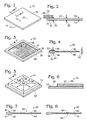
- Fig. 1 is an isometric view of an unetched hydrogen-permeable metal membrane.
- Fig. 2 is a cross-sectional detail of the membrane of Fig. 1 with an attached frame.
- Fig. 3 is an isometric view of the membrane of Fig. 1 after being etched according to a method of the present invnetion.
- Fig. 4 is a cross-sectional detail of the membrane of Fig. 3.
- Fig. 5 is an isometric view of the membrane of Fig. 1 with an absorbent medium placed over an application region of one of the membrane's surfaces.
- Fig. 6 is a cross-sectional detail of the membrane of Fig. 5.
- Fig. 7 is the detail of Fig. 4 with a hole indicated generally at 60.
- Fig. 8 is the detail of Fig. 7 with the hole repaired.
- An unetched hydrogen-permeable membrane is shown in Fig. 1 and indicated generally at 10.
Membrane 10 includes a pair of generallyopposed surfaces edge 16 joining the perimenters of the surfaces. Eachsurface outer edge region 18 that surrounds acentral region 20.Membrane 10 is typically roll formed and, as shown, has a generally rectangular, sheet-like configuration with a constant thickness. It should be understood thatmembrane 10 may have any geometric or irregular shape, such as by cutting the formed membrane into a desired shape based on user preferences or application requirements. - In Fig. 2,
membrane 10 is shown in cross-section, and it can be seen that thethickness 22 of the membrane measured between the central regions is the same as thethickness 24 measured between the edge regions. In the figures, it should be understood that the thicknesses of the membranes and subsequently described absorbent media and frame have been exaggerated for purposes of illustration. Typically, hydrogen-permeable membranes have thicknesses less than approximately 50 µm, although the disclosed etching process may be used with thicker membranes. - Also shown in Fig. 2 is a portion of a
frame 26, which may be secured to the membrane, such as around a portion or theentire edge region 18.Frame 26 is formed from a more durable material than the membrane and provides a support structure for the membrane.Frame 26 may be secured to one or both surfaces of the membrane. - In use,
membrane 10 provides a mechanism for removing hydrogen from mixtures of gasses because it selectively allows hydrogen to permeate through the membrane. The flowrate, or flux, of hydrogen throughmembrane 10 typically is accelerated by providing a pressure differential between a mixed gaseous mixture on one side of the membrane, and the side of the membrane to which hydrogen migrates, with the mixture side of the membrane being at a higher pressure than the other side. -
Membrane 10 is formed of a hydrogen-permeable metal or metal alloy, such as palladium or a palladium alloy. An example of such an alloy is comprised of 60 wt% palladium and 40 wt% copper (generally known as Pd-40Cu). Because palladium and palladium alloys are expensive, the thickness of the membrane should be minimal; i.e., as thin as possible without introducing an excessive number of holes in the membrane. Holes in the membrane are not desired because holes allow all gaseous components, including impurities, to pass through the membrane, thereby counteracting the hydrogen-selectivity of the membrane. - It is known to roll form hydrogen-permeable metal membranes, such as
membrane 10, to be very thin, such as with thicknesses of less than approximately 50 µm, and more commonly with thicknesses of approximately 25 µm. The flux through a hydrogen-permeable metal membrane is inversely proportional to the membrane thickness. Therefore, by decreasing the thickness of the membrane, it is expected that the flux through the membrane will increase, and vice versa. In Table 1, below, the expected flux of hydrogen through various thicknesses of Pd-40Cu membranes is shown.TABLE 1 Expected hydrogen flux through Pd-40Cu membranes at 400 °C and 100 psig (690 kPa gauge pressure) hydrogen feed, permeate hydrogen at ambient pressure. Membrane Thickness Expected Hydrogen Flux 25 µm 60 mL/cm2•min 17 µm 88 mL/cm2•min 15 µm 100 mL/cm2•min - Besides the increase in flux obtained by decreasing the thickness of the membrane, the cost to obtain the membrane also increases as the membrane's thickness is reduced. Also, as the thickness of a membrane decreases, the membrane becomes more fragile and difficult to handle without damaging.
- Through the etching process, or method, of the present invention, discussed in more detail subsequently, the thickness of a portion of the membrane, such as
central portion 20, may be selectively reduced, while leaving the remaining portion of the membrane, such asedge region 18, at its original thickness. Therefore, greater flux is obtained in the thinner etched region, while leaving a thicker, more durable edge region that bounds the central region and thereby provides support to the membrane. - For example, an etched membrane prepared according to an etching method of the present invention is shown in Fig. 3 and illustrated generally at 30. Like
membrane 10,membrane 30 includes a pair of generallyopposed surfaces edge 36 joining the surfaces. Eachsurface outer edge region 38 that surrounds acentral region 40.Membrane 30 is formed from any of the above-discussed hydrogen-permeable metal materials, and may have any of the above-discussed configurations and shapes. Unlikemembrane 10, however, the thickness ofmembrane 30 measured betweencentral regions 40 is less than thethickness 44 measured between the edge regions, as schematically illustrated in Fig. 4. Therefore, the hydrogen flux through the central region will be greater than that through the edge region, as expected from the above discussion of the inversely proportional relationship between membrane thickness and hydrogen flux. - However, an unexpected benefit of chemically etching the membrane, as disclosed herein, is that the hydrogen flux through the etched region exceeds that expected or measured through roll-formed membranes of equal thickness. As shown below in Table 2, the method of the present invention yields a hydrogen-permeable metal membrane with significantly greater flux than unetched membranes of similar thicknesses.
TABLE 2 Hydrogen flux through etched and unetched Pd-40Cu membranes at 400 °C and 100 psig (690 kPa gauge pressure) hydrogen feed, permeate hydrogen at ambient pressure. Aqua regia etchant. Etching Time Membrane Thickness Observed Hydrogen Flux Expected Hydrogen Flux None 25 µm 60 mL/cm2• min 60 mL/cm2•min 2.0 mins. 17 µm 94 mL/cm2•min 88 mL/cm2•min 2.5 mins. 15 µm 122 mL/cm2•min 100 mL/cm2•min - As the above table demonstrates, the invented method produces hydrogen-permeable metal membranes that permit increased hydrogen throughput compared to unetched membranes of similar thickness by increasing the roughness and surface area of the etched region of the membrane. Perhaps more importantly, this increase in throughput is achieved without sacrificing selectivity for hydrogen or the purity of the harvested hydrogen gas which is passed through the membrane.
- Increasing the surface roughness of the membrane is especially beneficial as the thickness of the membrane is reduced to less than 25 µm, especially less than 20 µm. As the membrane thickness is reduced, the surface reaction rates governing the transport of gaseous molecular hydrogen onto the surface of the metal membrane become more important to the overall permeation rate of hydrogen across the membrane. In extreme cases in which the membrane is quite thin (less than approximately 15 µm) the surface reaction rates are significant in governing the overall permeation rate of hydrogen across the membrane. Therefore, increasing the surface area increases the rate of hydrogen permeation. This contrasts with relatively thick membranes (greater than 25 µm) in which the surface reaction rates are less important and the overall permeation rate of hydrogen across the membrane is governed by the bulk diffusion of hydrogen through the membrane.
- Thus the etching process results in an overall reduction in the thickness of the membrane and an increase in the surface roughness (and surface area) of the membrane. These improvements yield an increase in hydrogen flux and reduce the amount of material (e.g., palladium alloy) that is required, while still maintaining the membrane's selectivity for hydrogen.
- In the invented etching process, an etchant is used to selectively reduce the thickness of the membrane. When the etchant removes, or etches, material from the surface of a membrane, the etchant also increases the surface roughness and surface area of the membrane in the etched region.
- Examples of suitable etchants are oxidizing agents and acids. For example, oxidizing acids such as nitric acid. Other suitable examples are combinations of nitric acid with other acids, such as aqua regia (a mixture of 25 vol% concentrated nitric acid and 75 vol% concentrated hydrochloric acid). Another specific example of an etchant well-suited to use in the present invention is a mixture comprising 67 wt% concentrated nitric acid and 33 wt% aqueous solution of poly(vinyl alcohol). A suitable method of preparing the aqueous solution of poly(vinyl alcohol) is to dissolve 4 wt% of poly(vinyl alcohol) (average molecular weight 124,000 to 186,000; 87% to 89% hydrolyzed; Aldrich Chemical Company, Milwaukee, WI) in de-ionized water. The disclosed examples of etchants are for illustrative purposes, and should not be construed to be limiting examples. For example, the relative percentage of acid may be increased or decreased to make the etchant respectively more or less reactive, as desired.
- In a first method of the present invention, a selected etchant is applied to at least one of the surfaces of the membrane. Once applied, the etchant removes material from the surface of the membrane, thereby increasing its surface roughness and reducing the thickness of the membrane in the etched region. After a defined time period, the etchant is removed. The etching process disclosed herein typically is conducted under ambient conditions (temperature and pressure), although it should be understood that the process could be conducted at elevated or reduced temperatures and pressures as well.
- The etching process is limited either by the time during which the membrane is exposed to the etchant, or by the reactive elements of the etchant. In the latter scenario, it should be understood that the etching reaction is self-limiting, in that the reaction will reach an equilibrium state in which the concentration of dissolved membrane in the etchant solution remains relatively constant. Regardless of the limiting factor in the process, it is important to apply a volume and concentration of etchant for a time period that will not result in the etchant creating substantial holes in, or completely dissolving, the membrane. Preferably, no holes are created in the membrane during the etching process.
- When applying the etchant to a surface of
membrane 10, such as to producemembrane 30, it is desirable to control the region of the surface over which the etchant extends. It is also desirable to maintain an even distribution of etchant over this application region. If the application region of the etchant is not controlled, then the etchant may remove material from other non-desired regions of the membrane, such as the edge region, or may damage materials joined to the membrane, such as an attached frame. If an even distribution of etchant is not maintained, areas of increased etchant may have too much material removed, resulting in holes in the membrane. Similarly, other areas may not have enough material removed, resulting in less than the desired reduction in thickness and increase in flux. - To control the distribution of etchant within the desired application region, an absorbent medium is placed on the
membrane 10 and defines an application region to be etched. For example, in Figs. 5 and 6, the absorbent medium is generally indicated at 50 and coversapplication region 52 ofsurface 12. As shown, medium 50 is sized to cover only a central portion ofsurface 12, however, it should be understood that medium 50 may be selectively sized to define application regions of any desired size and shape, up to the complete expanse ofsurface 12. Typically, however, only a central portion of each surface is treated, leaving an unetched perimeter of greater thickness than the central region. This unetched region, because of its greater thickness, provides strength and support tomembrane 10 while still contributing to the hydrogen permeability of the membrane. - Besides being selected to absorb the particular etchant without adversely reacting to the etchant or metal membrane, it is preferable that
medium 50 has a substantially uniform absorbency and diffusivity along its length. When medium 50 absorbs and distributes the etchant uniformly along its length, it distributes the etchant evenly across the application region, thereby removing substantially the same amount of material across the entire application region. The benefit of this is not only that some etchant will contact, and thereby remove material from, the entire application region, but also that the etchant will be uniformly distributed across the application region. Therefore,membrane 50 prevents too much etchant being localized in an area, which would result in too much material being removed. In a region where too much etchant is applied, the excess etchant is drawn away from that region to other areas of the medium where less etchant is applied. Similarly, in a region where too little etchant is applied, the medium draws etchant to that region to produce an even distribution across the medium, and thereby across the application region. - As a result, the reduction of thickness in
membrane 10 will be relatively uniform across the application region, and perhaps more importantly will be reproducible regardless of the exact rate and position at which the etchant is applied. Therefore, with the same size and type ofmedium 50 and the same volume ofetchant 54, the resulting reduction in thickness should be reproducible for membranes of the same composition. Of course, it should be understood that etching removes material from the surface of the membrane, thereby resulting in an uneven, rough surface with increased surface area over an unetched surface. Therefore, the exact surface topography will not be seen. However, the average thickness measured across a section of the membrane should be reproducible. For example, in Fig. 4, the average thickness betweencentral regions 40 is indicated with dashed lines. - Because
medium 50 essentially defines the bounds ofapplication region 52, medium 50 should be sized prior to placing it upon the surface to be etched. After placing the medium in the desired position on one of the membrane's surfaces, such assurface 12 shown in Fig. 5, a volume of etchant is applied. In Fig. 5, the applied volume of etchant is schematically illustrated at 54, witharrows 56 illustrating the absorption and distribution ofetchant 54 acrossmedium 50. - The applied volume of etchant should be no more than a saturation volume of etchant. An absorbent medium can only absorb up to a defined volume of a particular etchant per unit of medium 50 before reaching the saturation point of the medium. Therefore, it is important not to exceed this saturation point. Too much applied etchant will result in unabsorbed etchant pooling on or adjacent the medium, such as on the upper surface of
medium 50 or around the edges of the medium. When excess etchant contacts the surface, it is likely to result in holes in the membrane because more than the desired amount of material is removed. As discussed, if these holes are numerous or large enough, they will render the membrane unusable for hydrogen purification applications, with any holes lowering the purity of the hydrogen passing through the membrane. - Therefore, to prevent too much etchant from being applied, the volume of etchant applied may approach, but should not exceed, the saturation volume of the etchant.
- An example of a suitable absorbent medium is a cellulosic material, such as absorbent paper products. A particular example of an absorbent medium that has proven effect is single-fold paper towels manufactured by the Kimberly Clark company. When a three inch by three inch area of such a towel is used, approximately 2.5 mL of etchant may be applied without exceeding the saturation volume of that area. The capillary action of the cellulosic towel both absorbs the applied etchant and distributes the etchant throughout the towel. Other paper and cellulosic materials may be used as well, as long as they meet the criteria defined herein. Absorbent, diffusive materials other than cellulosic materials may be used as well.
- After applying the etchant to
medium 50, the etchant is allowed to remove material from the application region for a determined time period. This period is best determined through experimentation and will vary depending on such factors as the composition, thickness and desired thickness of the membrane, the absorbent medium being used, the composition and concentration of etchant, and the temperature at which the etching process is conducted. After this time period has passed, the medium is removed from the membrane, and the application, or treatment, area is rinsed with water to remove any remaining etchant. After rinsing, the method may be repeated to etch another surface of the membrane. - Instead of a single etching step on each surface of the membrane, a variation of the above method includes plural etching steps for each surface to be etched. In the first step, a more reactive, or vigorous etchant is used to remove a substantial portion of the material to be removed. In the second step, a less reactive etchant is used to provide a more controlled, even etch across the application region.
- As an illustrative example, Pd-40Cu alloy foil was etched first with concentrated nitric acid for 20-30 seconds using the absorbent medium technique described above. After removing the medium and rinsing and drying the membrane, a second etch with a mixture of 20 vol% neat ethylene glycol and the balance concentrated nitric acid was performed for between 1 and 4 minutes. Subsequent etching steps were performed with the glycol mixture to continue to gradually reduce the thickness of the membrane in the application region. Results of etching Pd-40Cu foil using this method are given in the table below.
TABLE 3 Results of etching Pd-40Cu membrane with concentrated nitric acid for 30 seconds followed by subsequent etches with concentrated nitric acid diluted with 20%vol ethylene glycol. Etching Solution Etching Time Observations None (Virgin Pd-40Cu Foil) N/A Measures 0.0013 inches (33 µm) thick 1) Conc. Nitric Acid 1) 30 seconds Measures 0.0008 to 0.0009 inches (20 µm-22µm) thick, no pin holes 2) 20vol% ethylene glycol/ HNO3 2) 1.5 minutes 1) Conc. Nitric Acid 1) 30 seconds Measures 0.0005 to 0.0006 inches (13µm -15µm) thick, no pin holes 2) 20vol% ethylene glycol/ HNO3 2) 1.5 minutes 3) 1.5 minutes 3) 20vol% ethylene glycol/HNO3 1) Conc. Nitric Acid 1)30 seconds Measures 0.0005 inches (13µm) thick, no pin holes in membrane 2) 20vol% ethylene glycol/ HNO3 2) 3 minutes 1) Conc. Nitric Acid 1) minute Multiple pin holes in membrane 2) 20vol% ethylene glycol/ HNO3 2) 3 minutes - Other than confining the etching solution to a desired application region, another benefit of using an absorbent medium to control the placement and distribution of the etchant is that the quantity of etchant (or etching solution) that may be applied without oversaturating the medium is limited. Thus, the etching reaction may be self-limiting, depending on the choice of and composition of etchant. For instance, varying the etching time using 33.3wt% PVA solution/66.7wt% concentrated HNO3 yielded the results shown in the following table. These results indicate that the volume of etchant that is applied at one time may limit the depth of etching, so long as the etchant is not so reactive or applied in sufficient quantity to completely dissolve the application region.
TABLE 4 Results of etching Pd-40Cu membrane with a solution of 33.3wt% PVA solution/66.7wt% concentrated nitric acid. Etching Time Observations 0 Measures 0.0013 inches (33µm) thick 3 minutes Measures 0.0011 inches (28µm) thick 4 minutes Measures 0.0011 inches (28µm) thick 5 minutes Measures 0.0011 inches (28µm) thick 6 minutes Measures 0.0011 inches (28µm) thick 3 minutes, rinse, 3 minutes Measures 0.0008 to 0.0009 inches (20µm-22µm) thick 3 minutes, rinse, 3 minutes, rinse, 3 minutes Measures 0.0006 inches (15µm) thick, multiple pin holes - In a further variation of the etching method, a suitable mask may be applied to the membrane to define the boundaries of the region to be etched. For example, in Fig. 5, instead of using
absorbent medium 50 to defineapplication region 52, a non-absorbent mask could be applied aroundedge region 38. Because this mask does not absorb the etchant, it confines the etchant to an application region bounded by the mask. Following etching, the mask is removed. The mask may be applied as a liquid or it may be a film with an adhesive to bond the film to the membrane. - If the chemical etching process is not properly controlled, tiny holes will appear in the membrane. For example, in Fig. 7
membrane 30 is shown with ahole 60 in itscentral region 40. Typically, the holes will be very small, however, the size of a particular hole will depend on the concentration and quantity of etchant applied to that region, as well as the time during which the etchant was allowed to etch material from the membrane. Holes, such ashole 60, reduce the purity of the hydrogen gas harvested through the membrane, as well as the selectivity of the membrane for hydrogen. The probability of holes forming in the membrane during the etching process increases as the thickness of the membrane is reduced. Therefore, there is often a need to repair any holes formed during the etching process. - One method for detecting any such holes is to utilize a light source to identify holes in the membrane. By shining a light on one side of the membrane, holes are detected where light shines through the other side of the membrane. The detected holes may then be repaired by spot electroplating, such as by using a Hunter Micro-Metallizer Pen available from Hunter Products, Inc., Bridgewater, NJ. In Fig. 8, a patch, or plug, 62 is shown repairing
hole 60. Any other suitable method may be used for repairing tiny holes resulting from etching the membrane. - The repairing step of the invented etching process also may be performed using a photolithographic method. In this case a light-sensitive, electrically insulating mask is applied to one surface of the membrane, and then the membrane is irradiated with light of the appropriate wavelength(s) from the opposite side. Any tiny holes that might be present in the membrane will allow the light to pass through the membrane and be absorbed by the light-sensitive mask. Next, the mask is washed to remove irradiated regions of the mask and thereby reveal the bare metal of the membrane. Because only the irradiated regions of the mask are removed, the remaining mask serves as an electrical insulator over the surface of the membrane. Then, all of the spots where the mask has been removed are electroplated or electrolessplated at the same time.
- Because the patch, or plug, represents only a minute percentage of the surface area of the membrane, the patch may be formed from a material that is not hydrogen-permeable without the flux through the membrane being noticeably affected. Of course, a hydrogen-permeable and selective patch is preferred. Suitable metals for electroplating to fill or close tiny holes in the palladium-alloy membranes include copper, silver, gold, nickel, palladium, chromium, rhodium, and platinum. Volatile metals such as zinc, mercury, lead, bismuth and cadmium should be avoided. Furthermore, it is preferable that metal applied by plating be relatively free of phosphorous, carbon, sulfur and nitrogen, since these heteroatoms could contaminate large areas of the membrane and are generally known to reduce the permeability of palladium alloys to hydrogen.
Claims (39)
- A method for preparing a hydrogen permeable metal membrane, characterised by:applying an etchant to a region of at least one of the opposed surfaces of a hydrogen permeable metal membrane to reduce the thickness and increase the surface roughness of the membrane in the region compared to the thickness and surface roughness of the membrane prior to applying the etchant.
- The method of claim 1, wherein the method further includes placing a mask on the membrane to define the region to which the etchant is applied.
- The method of claim 2, wherein the method further includes adhesively bonding the mask to the membrane prior to applying the etchant.
- The method of any preceding claim, wherein the method further includes placing an absorbent medium on the region prior to applying the etchant.
- The method of claim 4, wherein the medium at least substantially confines the etchant to an application region and distributes the etchant throughout the region.
- The method of claim 4 or claim 5, wherein the method further includes removing the medium and the etchant after a determined time period.
- The method of any of claims 4, 5 or 6, wherein the volume of etchant applied to the medium does not exceed the saturation volume of the medium.
- The method of any of claims 4 to 7, wherein the method includes removing the medium and the etchant and repeating the placing and applying steps.
- The method of claim 8 wherein the method includes removing the medium and the etchant, repeating the placing step to place a second absorbent medium on the application region and applying a second etchant to the second medium.
- The method of claim 9, wherein the second etchant is less reactive, as applied to the membrane, than the previously applied etchant.
- The method of any of claims 4 to 10, wherein the placing and applying steps performed on one surface of the membrane are repeated with respect to the other surface of the membrane.
- The method of any of claims 1 to 11, wherein the region is smaller than the selected one of the surfaces of the membrane.
- The method of any of claims 1 to 11, wherein the region is at least substantially coextensive with one of the surfaces of the membrane.
- The method of any of claims 1 to 13, wherein after the applying step, the method includes detecting any holes in the membrane.
- The method of claim 14, wherein the method further includes repairing detected holes.
- The method of claim 15, wherein the repairing step includes repairing detected holes by electroplating, optionally with a hydrogen-permeable material.
- The method of claim 15, wherein the repairing step includes repairing detected holes by electroless plating.
- The method of any of claims 15 to 17 wherein the repairing step includes repairing detected holes by photolithography.
- The method of any of claims 1 to 18, wherein the hydrogen permeable metal membrane is a hydrogen-selective metal membrane.
- The method of any of claims 1 to 19, wherein the hydrogen permeable metal membrane is formed of palladium or a palladium alloy.
- The method of any of claims 1 to 19, wherein the hydrogen permeable metal membrane is formed of a palladium alloy.
- The method of any of claims 1 to 21, wherein the thickness of the etched region is less than 20 microns.
- The method of claim 22, wherein the thickness is less than 15 microns.
- The method of any of claims 1 to 23, wherein the thickness of the etched region is less than 80% of the thickness of the unetched region.
- The method of claim 24 wherein the thickness of the etched region is between 40% and 70% of the thickness of the unetched region.
- A hydrogen-permeable metal membrane, comprising:a hydrogen-permeable metal membrane formed at least substantially from a hydrogen permeable material and characterised by having an etched region and an unetched region, and further wherein the etched region of the membrane is thinner than the unetched region.
- The membrane of claim 26, wherein the unetched region at least partially surrounds the etched region.
- The membrane of claim 26, wherein the unetched region surrounds the etched region.
- The membrane of any of claims 26 to 28, wherein the membrane is coupled to a frame.
- The membrane of claims 29, wherein at least a portion of the unetched region of the membrane is coupled to the frame.
- The membrane of any of claims 26 to 30, wherein the hydrogen permeable metal membranes is a hydrogen-selective metal membrane.
- The membrane of any of claims 26 to 31, wherein the hydrogen permeable metal membrane is formed of palladium or a palladium alloy.
- The membrane of any of claims 26 to 31, wherein the hydrogen permeable metal membrane is formed of a palladium alloy.
- The membrane of any of claims 26 to 33, wherein the thickness of the etched region is less than 20 microns.
- The membrane of claim 34, wherein the thickness is less than 15 microns.
- The membrane of any of claims 26 to 35, wherein the thickness of the etched region is less than 80% of the thickness of the unetched region.
- The membrane of claim 36 wherein the thickness of the etched region is between 40% and 70% of the thickness of the unetched region.
- The use of a membrane as claimed in any of claims 26 to 37 to purity hydrogen.
- The use of claim 38 wherein the hydrogen is used as a fuel source for a fuel cell.
Applications Claiming Priority (3)
| Application Number | Priority Date | Filing Date | Title |
|---|---|---|---|
| US274154 | 1999-03-22 | ||
| US09/274,154 US6152995A (en) | 1999-03-22 | 1999-03-22 | Hydrogen-permeable metal membrane and method for producing the same |
| PCT/US2000/007458 WO2000056425A1 (en) | 1999-03-22 | 2000-03-20 | Hydrogen-permeable metal membrane and method for producing the same |
Publications (3)
| Publication Number | Publication Date |
|---|---|
| EP1189678A1 EP1189678A1 (en) | 2002-03-27 |
| EP1189678A4 EP1189678A4 (en) | 2005-05-04 |
| EP1189678B1 true EP1189678B1 (en) | 2007-07-04 |
Family
ID=23047008
Family Applications (1)
| Application Number | Title | Priority Date | Filing Date |
|---|---|---|---|
| EP00918200A Expired - Lifetime EP1189678B1 (en) | 1999-03-22 | 2000-03-20 | Hydrogen-permeable metal membrane and method for producing the same |
Country Status (10)
| Country | Link |
|---|---|
| US (2) | US6152995A (en) |
| EP (1) | EP1189678B1 (en) |
| JP (1) | JP3537768B2 (en) |
| AT (1) | ATE366136T1 (en) |
| AU (1) | AU754812B2 (en) |
| BR (1) | BR0009185A (en) |
| CA (1) | CA2367839C (en) |
| DE (1) | DE60035418T2 (en) |
| MX (1) | MXPA01009435A (en) |
| WO (1) | WO2000056425A1 (en) |
Cited By (6)
| Publication number | Priority date | Publication date | Assignee | Title |
|---|---|---|---|---|
| US8961627B2 (en) | 2011-07-07 | 2015-02-24 | David J Edlund | Hydrogen generation assemblies and hydrogen purification devices |
| US9187324B2 (en) | 2012-08-30 | 2015-11-17 | Element 1 Corp. | Hydrogen generation assemblies and hydrogen purification devices |
| US9914641B2 (en) | 2012-08-30 | 2018-03-13 | Element 1 Corp. | Hydrogen generation assemblies |
| US10273423B2 (en) | 2014-11-12 | 2019-04-30 | Element 1 Corp. | Refining assemblies and refining methods for rich natural gas |
| US11505755B2 (en) | 2017-07-20 | 2022-11-22 | Proteum Energy, Llc | Method and system for converting associated gas |
| US11590449B2 (en) | 2012-08-30 | 2023-02-28 | Element 1 Corp | Hydrogen purification devices |
Families Citing this family (79)
| Publication number | Priority date | Publication date | Assignee | Title |
|---|---|---|---|---|
| US6783741B2 (en) | 1996-10-30 | 2004-08-31 | Idatech, Llc | Fuel processing system |
| US6537352B2 (en) | 1996-10-30 | 2003-03-25 | Idatech, Llc | Hydrogen purification membranes, components and fuel processing systems containing the same |
| US6319306B1 (en) | 2000-03-23 | 2001-11-20 | Idatech, Llc | Hydrogen-selective metal membrane modules and method of forming the same |
| US6152995A (en) | 1999-03-22 | 2000-11-28 | Idatech Llc | Hydrogen-permeable metal membrane and method for producing the same |
| US6494937B1 (en) | 2001-09-27 | 2002-12-17 | Idatech, Llc | Hydrogen purification devices, components and fuel processing systems containing the same |
| US7195663B2 (en) * | 1996-10-30 | 2007-03-27 | Idatech, Llc | Hydrogen purification membranes, components and fuel processing systems containing the same |
| US6547858B1 (en) | 1999-03-22 | 2003-04-15 | Idatech, Llc | Hydrogen-permeable metal membrane and hydrogen purification assemblies containing the same |
| US6602325B1 (en) | 1999-10-21 | 2003-08-05 | Ati Properties, Inc. | Fluid separation assembly |
| US6419726B1 (en) | 1999-10-21 | 2002-07-16 | Ati Properties, Inc. | Fluid separation assembly and fluid separation module |
| DE19983751B4 (en) * | 1998-11-10 | 2008-04-17 | ATI Properties, Inc., Gardena | Hydrogen Segregation membrane |
| US6835232B2 (en) * | 1998-11-10 | 2004-12-28 | Frost Chester B | Fluid separation assembly and fluid separation module |
| US6767389B2 (en) | 1999-03-22 | 2004-07-27 | Idatech, Llc | Hydrogen-selective metal membranes, membrane modules, purification assemblies and methods of forming the same |
| US6596057B2 (en) | 1999-03-22 | 2003-07-22 | Idatech, Llc | Hydrogen-selective metal membranes, membrane modules, purification assemblies and methods of forming the same |
| US6315820B1 (en) * | 1999-10-19 | 2001-11-13 | Ford Global Technologies, Inc. | Method of manufacturing thin metal alloy foils |
| US6537310B1 (en) * | 1999-11-19 | 2003-03-25 | Advanced Bio Prosthetic Surfaces, Ltd. | Endoluminal implantable devices and method of making same |
| US7201783B2 (en) * | 2000-11-13 | 2007-04-10 | Idatech, Llc | Fuel processing system and improved feedstock therefor |
| US6475268B2 (en) * | 2000-12-22 | 2002-11-05 | Ford Global Technologies, Inc. | Supported membrane for hydrogen separation |
| US7922781B2 (en) | 2001-03-02 | 2011-04-12 | Chellappa Anand S | Hydrogen generation apparatus and method for using same |
| WO2002071451A2 (en) | 2001-03-02 | 2002-09-12 | Mesosystems Technology, Inc. | Ammonia-based hydrogen generation apparatus and method for using same |
| US7867300B2 (en) | 2001-03-02 | 2011-01-11 | Intelligent Energy, Inc. | Ammonia-based hydrogen generation apparatus and method for using same |
| US6569227B2 (en) | 2001-09-27 | 2003-05-27 | Idatech, Llc | Hydrogen purification devices, components and fuel processing systems containing the same |
| US6890672B2 (en) | 2001-06-26 | 2005-05-10 | Idatech, Llc | Fuel processor feedstock delivery system |
| US6888014B2 (en) * | 2001-07-24 | 2005-05-03 | Panagin Pharmaceuticals Inc. | Dammarane sapogenins, their use as anti-cancer agents, and a process for producing same |
| JP2003094542A (en) * | 2001-09-25 | 2003-04-03 | Toyo Kohan Co Ltd | Laminated material with opening and component using laminated material with opening |
| JP2003093854A (en) * | 2001-09-25 | 2003-04-02 | Toyo Kohan Co Ltd | Method for producing opened laminate and method for producing component using opened laminate |
| US7632321B2 (en) * | 2001-11-01 | 2009-12-15 | Idatech, Llc | Fuel processing systems, fuel cell systems, and improved feedstocks therefor |
| US7169489B2 (en) | 2002-03-15 | 2007-01-30 | Fuelsell Technologies, Inc. | Hydrogen storage, distribution, and recovery system |
| EP1499452B1 (en) | 2002-04-03 | 2013-12-18 | Colorado School Of Mines | Process for preparing palladium alloy composite membranes for use in hydrogen separation |
| US8101243B2 (en) * | 2002-04-03 | 2012-01-24 | Colorado School Of Mines | Method of making sulfur-resistant composite metal membranes |
| US20030223926A1 (en) * | 2002-04-14 | 2003-12-04 | Edlund David J. | Steam reforming fuel processor, burner assembly, and methods of operating the same |
| US8172913B2 (en) | 2002-04-23 | 2012-05-08 | Vencill Thomas R | Array of planar membrane modules for producing hydrogen |
| US7527661B2 (en) | 2005-04-18 | 2009-05-05 | Intelligent Energy, Inc. | Compact devices for generating pure hydrogen |
| JP2004008966A (en) * | 2002-06-07 | 2004-01-15 | Mitsubishi Heavy Ind Ltd | Hydrogen separating membrane, hydrogen separating unit and method for manufacturing the membrane |
| US7128769B2 (en) * | 2002-06-27 | 2006-10-31 | Idatech, Llc | Methanol steam reforming catalysts, steam reformers, and fuel cell systems incorporating the same |
| EP1541221A4 (en) * | 2002-07-25 | 2006-04-05 | Dainippon Printing Co Ltd | Thin film supporting substrate used in filter for hydrogen production and method for manufacturing filter for hydrogen production |
| US7341609B2 (en) * | 2002-10-03 | 2008-03-11 | Genesis Fueltech, Inc. | Reforming and hydrogen purification system |
| CA2410927A1 (en) * | 2002-11-05 | 2004-05-05 | Michel Petitclerc | Electrically heated reactor for reforming in gaseous phase |
| US7537738B2 (en) * | 2003-01-21 | 2009-05-26 | Gm Global Technology Operations, Inc. | Fuel processing system having a membrane separator |
| ITTO20030032A1 (en) * | 2003-01-24 | 2004-07-25 | Varian Spa | SELECTIVELY GAS PERMEABLE MEMBRANE AND METHOD FOR ITS REALIZATION. |
| EP1606040A2 (en) * | 2003-03-21 | 2005-12-21 | Worcester Polytechnic Institute | Composite gas separations modules having intermediate metal layers |
| AU2004224371B2 (en) * | 2003-03-21 | 2008-07-31 | Worcester Polytechnic Institute | Method for fabricating composite gas separation modules |
| DK1603660T3 (en) * | 2003-03-21 | 2009-01-19 | Worcester Polytech Inst | Process for curing defects in the manufacture of a composite gas separation module |
| AU2004237778B2 (en) * | 2003-05-02 | 2008-08-14 | Worcester Polytechnic Institute | Composite gas separation modules having high tamman temperature intermediate layers |
| US20050084388A1 (en) * | 2003-07-17 | 2005-04-21 | Hayes Alan E. | Positive displacement liquid pump |
| JP4193750B2 (en) * | 2004-04-26 | 2008-12-10 | トヨタ自動車株式会社 | Hydrogen separation membrane, fuel cell, and method for producing the hydrogen separation membrane and fuel cell |
| US7727596B2 (en) * | 2004-07-21 | 2010-06-01 | Worcester Polytechnic Institute | Method for fabricating a composite gas separation module |
| US7297183B2 (en) * | 2004-09-20 | 2007-11-20 | Idatech, Llc | Hydrogen purification devices, components, and fuel processing systems containing the same |
| US7632322B2 (en) | 2005-06-07 | 2009-12-15 | Idatech, Llc | Hydrogen-producing fuel processing assemblies, heating assemblies, and methods of operating the same |
| US7659019B2 (en) | 2005-09-16 | 2010-02-09 | Idatech, Llc | Thermally primed hydrogen-producing fuel cell system |
| US7601302B2 (en) | 2005-09-16 | 2009-10-13 | Idatech, Llc | Self-regulating feedstock delivery systems and hydrogen-generating fuel processing assemblies and fuel cell systems incorporating the same |
| TWI328898B (en) | 2005-09-16 | 2010-08-11 | Idatech L L C | Self-regulating feedstock delivery systems and hydrogen-generating fuel processing assemblies and fuel cell systems incorporating the same |
| US7824654B2 (en) | 2005-11-23 | 2010-11-02 | Wilson Mahlon S | Method and apparatus for generating hydrogen |
| US20070262051A1 (en) * | 2006-05-12 | 2007-11-15 | Advanced Chip Engineering Technology Inc. | Method of plasma etching with pattern mask |
| US7972420B2 (en) | 2006-05-22 | 2011-07-05 | Idatech, Llc | Hydrogen-processing assemblies and hydrogen-producing systems and fuel cell systems including the same |
| US7629067B2 (en) | 2006-05-22 | 2009-12-08 | Idatech, Llc | Hydrogen-producing fuel processing systems and fuel cell systems with a liquid leak detection system |
| US7939051B2 (en) | 2006-05-23 | 2011-05-10 | Idatech, Llc | Hydrogen-producing fuel processing assemblies, heating assemblies, and methods of operating the same |
| US7700184B2 (en) * | 2006-08-14 | 2010-04-20 | University Of Houston System | Pd nanopore and palladium encapsulated membranes |
| JP2010523315A (en) * | 2007-04-05 | 2010-07-15 | ウスター ポリテクニック インスティチュート | COMPOSITE STRUCTURE WITH POROUS ANODE OXIDE LAYER AND METHOD FOR MANUFACTURING |
| US9044715B2 (en) * | 2007-08-22 | 2015-06-02 | Colorado School Of Mines | Unsupported palladium alloy membranes and methods of making same |
| US8262752B2 (en) | 2007-12-17 | 2012-09-11 | Idatech, Llc | Systems and methods for reliable feedstock delivery at variable delivery rates |
| JP5235489B2 (en) * | 2008-05-13 | 2013-07-10 | 大日本印刷株式会社 | Hydrogen permselective membrane and method for producing the same |
| US20110061376A1 (en) * | 2009-02-17 | 2011-03-17 | Mcalister Technologies, Llc | Energy conversion assemblies and associated methods of use and manufacture |
| US8652239B2 (en) | 2010-05-03 | 2014-02-18 | Worcester Polytechnic Institute | High permeance sulfur tolerant Pd/Cu alloy membranes |
| US8920996B2 (en) | 2010-05-11 | 2014-12-30 | Dcns | Systems and methods for regulating fuel cell air flow during low loads or cold temperature operation |
| US8778058B2 (en) | 2010-07-16 | 2014-07-15 | Colorado School Of Mines | Multilayer sulfur-resistant composite metal membranes and methods of making and repairing the same |
| US8920732B2 (en) | 2011-02-15 | 2014-12-30 | Dcns | Systems and methods for actively controlling steam-to-carbon ratio in hydrogen-producing fuel processing systems |
| CN102786159B (en) * | 2012-08-09 | 2016-03-16 | 艾欧史密斯(中国)热水器有限公司 | Associating Scale inhibitors and antisludging equipment |
| US11738305B2 (en) | 2012-08-30 | 2023-08-29 | Element 1 Corp | Hydrogen purification devices |
| CN105163832A (en) | 2013-03-14 | 2015-12-16 | 埃利门特第一公司 | Hydrogen generation assemblies and hydrogen purification devices |
| US10384167B2 (en) | 2013-11-21 | 2019-08-20 | Oasys Water LLC | Systems and methods for improving performance of osmotically driven membrane systems |
| CN106102878B (en) * | 2013-11-21 | 2019-11-08 | 欧赛斯水务有限公司 | For repair membrane and the system and method for the performance for improving osmotic drive membranous system |
| US9828561B2 (en) | 2014-11-12 | 2017-11-28 | Element 1 Corp. | Refining assemblies and refining methods for rich natural gas |
| US9605224B2 (en) | 2014-11-12 | 2017-03-28 | Element 1 Corp. | Refining assemblies and refining methods for rich natural gas |
| US10809147B2 (en) | 2015-04-07 | 2020-10-20 | University Of New Brunswick | System and method for monitoring hydrogen flux |
| US10476093B2 (en) | 2016-04-15 | 2019-11-12 | Chung-Hsin Electric & Machinery Mfg. Corp. | Membrane modules for hydrogen separation and fuel processors and fuel cell systems including the same |
| TWI724933B (en) | 2018-01-04 | 2021-04-11 | 美商1號組件公司 | Hydrogen purification devices |
| US11177494B2 (en) | 2018-03-05 | 2021-11-16 | H2 Powertech, Llc | Systems and methods for forming a liquid mixture having a predetermined mix ratio and reforming systems, reforming methods, fuel cell systems, and fuel cell methods that utilize the liquid mixture |
| RU2725405C1 (en) * | 2019-09-02 | 2020-07-02 | Федеральное государственное унитарное предприятие "Крыловский государственный научный центр" (ФГУП "Крыловский государственный научный центр") | Method of repairing diffusion hydrogen separator |
| US11712655B2 (en) | 2020-11-30 | 2023-08-01 | H2 Powertech, Llc | Membrane-based hydrogen purifiers |
Family Cites Families (98)
| Publication number | Priority date | Publication date | Assignee | Title |
|---|---|---|---|---|
| US2824620A (en) | 1955-09-12 | 1958-02-25 | Universal Oil Prod Co | Purification of hydrogen utilizing hydrogen-permeable membranes |
| US3208198A (en) * | 1962-07-26 | 1965-09-28 | Engelhard Ind Inc | Method for hydrogen diffusion |
| US3350176A (en) | 1964-03-24 | 1967-10-31 | Engelhard Ind Inc | Hydrogen generator |
| US3356538A (en) * | 1964-09-29 | 1967-12-05 | Gen Electric | Electrodeposited ion exchange membrane and method of forming |
| US3336730A (en) | 1964-11-17 | 1967-08-22 | Union Carbide Corp | Hydrogen continuous production method and apparatus |
| US3469372A (en) * | 1965-06-18 | 1969-09-30 | Mitsubishi Gas Chemical Co | Hydrogen permeable membrane and hydrogen permeating assembly |
| US3428476A (en) | 1965-06-22 | 1969-02-18 | Engelhard Min & Chem | Method for producing hydrogen diffusion cells |
| US3450500A (en) | 1965-08-03 | 1969-06-17 | United Aircraft Corp | Method for catalytically reforming hydrogen-containing carbonaceous feed-stocks by simultaneous abstractions through a membrane selectively permeable to hydrogen |
| US3368329A (en) | 1965-08-10 | 1968-02-13 | Eguchi Takashi | Hydrogen purification apparatus |
| US3447288A (en) | 1965-08-23 | 1969-06-03 | Prototeck Inc | Gas-diffusion assembly including thin hydrogen-permeable impervious foil |
| US3439474A (en) | 1967-08-17 | 1969-04-22 | Union Carbide Corp | Method for hydrogen separation and purification |
| US3469944A (en) | 1968-05-13 | 1969-09-30 | Joseph P Bocard | Process and apparatus for the manufacture of hydrogen for fuel cells |
| US3520803A (en) | 1968-12-24 | 1970-07-21 | Ionics | Membrane fluid separation apparatus and process |
| US3564819A (en) | 1970-02-24 | 1971-02-23 | Gen Electric | Membrane package construction |
| US3665680A (en) * | 1970-12-18 | 1972-05-30 | Engelhard Min & Chem | Hydrogen diffusion apparatus |
| US3713270A (en) * | 1971-05-24 | 1973-01-30 | Nat Res Dev | Hydrogen diffusion membranes |
| US3849076A (en) * | 1972-06-21 | 1974-11-19 | V Gryaznov | Catalytic reactor for carrying out conjugate chemical reactions |
| US3761382A (en) | 1972-06-21 | 1973-09-25 | Triangle Environment Corp | Ers and the like apparatus for generating purifying and delivering hydrogen for analyz |
| FR2207747B1 (en) | 1972-11-24 | 1975-07-04 | Rhone Poulenc Ind | |
| BE795954A (en) | 1973-02-05 | 1973-08-27 | Uralsky Politekhn Inst | PROCESS FOR OBTAINING VERY HIGH PURITY HYDROGEN |
| US3839110A (en) * | 1973-02-20 | 1974-10-01 | Bell Telephone Labor Inc | Chemical etchant for palladium |
| US4003725A (en) | 1975-05-12 | 1977-01-18 | Trienco, Inc. | Apparatus for purifying hydrogen gas |
| US3972695A (en) | 1975-05-12 | 1976-08-03 | Trienco, Inc. | Hydrogen purifier |
| US4056373A (en) | 1976-05-12 | 1977-11-01 | Resource Systems, Inc. | Hydrogen-purification apparatus with palladium-alloy filter coil |
| US4132668A (en) * | 1977-04-06 | 1979-01-02 | Gryaznov Vladimir M | Method of preparing a hydrogen-permeable membrane catalyst on a base of palladium or its alloys for the hydrogenation of unsaturated organic compounds |
| US4329157A (en) * | 1978-05-16 | 1982-05-11 | Monsanto Company | Inorganic anisotropic hollow fibers |
| US4254086A (en) | 1978-12-27 | 1981-03-03 | Sanders Alfred P | Endothermal water decomposition unit for producing hydrogen and oxygen |
| US4468235A (en) | 1979-02-15 | 1984-08-28 | Hill Eugene F | Hydrogen separation using coated titanium alloys |
| US4197152A (en) * | 1979-03-14 | 1980-04-08 | Gte Sylvania Incorporated | Attaching self-supporting emissive film to cathode support |
| US4248688A (en) | 1979-09-04 | 1981-02-03 | International Business Machines Corporation | Ion milling of thin metal films |
| US4331520A (en) | 1979-10-26 | 1982-05-25 | Prototech Company | Process for the recovery of hydrogen-reduced metals, ions and the like at porous hydrophobic catalytic barriers |
| US4319923A (en) | 1979-12-26 | 1982-03-16 | Western Electric Co., Inc. | Recovery of gold and/or palladium from an iodide-iodine etching solution |
| US4422911A (en) | 1982-06-14 | 1983-12-27 | Prototech Company | Method of recovering hydrogen-reduced metals, ions and the like at porous catalytic barriers and apparatus therefor |
| US4472176A (en) | 1983-08-01 | 1984-09-18 | Resource Systems, Inc. | Apparatus and method for the production of pure hydrogen from a hydrogen-containing crude gas |
| DE3332345C2 (en) | 1983-09-08 | 1986-08-07 | Doduco KG Dr. Eugen Dürrwächter, 7530 Pforzheim | Filter material made of metal mesh |
| DE3332346A1 (en) | 1983-09-08 | 1985-04-04 | Kernforschungsanlage Jülich GmbH, 5170 Jülich | HYDROGEN PERMEATION WALL, METHOD FOR PRODUCING THE SAME AND THE USE THEREOF |
| US4650814A (en) * | 1984-03-07 | 1987-03-17 | Keller Arnold P | Process for producing methanol from a feed gas |
| DE3424208A1 (en) * | 1984-06-30 | 1986-01-16 | Kernforschungsanlage Jülich GmbH, 5170 Jülich | METHOD AND DEVICE FOR INCREASING THE SALES OF GAS REACTIONS PROCESSING WITH HYDROGEN PRODUCTION |
| US4654063A (en) * | 1984-12-21 | 1987-03-31 | Air Products And Chemicals, Inc. | Process for recovering hydrogen from a multi-component gas stream |
| US4684581A (en) * | 1986-07-10 | 1987-08-04 | Struthers Ralph C | Hydrogen diffusion fuel cell |
| US4810485A (en) * | 1986-08-25 | 1989-03-07 | Institute Of Gas Technology | Hydrogen forming reaction process |
| JPH0642940B2 (en) | 1987-03-31 | 1994-06-08 | 東洋エンジニアリング株式会社 | Device for gas endothermic reaction |
| JP2572612B2 (en) | 1987-11-30 | 1997-01-16 | 日本パイオニクス株式会社 | Hydrogen purification method |
| JP2596767B2 (en) | 1987-11-30 | 1997-04-02 | 日本パイオニクス株式会社 | Method and apparatus for purifying hydrogen |
| JPH07112532B2 (en) * | 1988-04-13 | 1995-12-06 | 昭和アルミニウム株式会社 | Method for manufacturing filtration membrane |
| FR2637817B1 (en) | 1988-10-17 | 1992-10-09 | Eurodia Sa | SEPARATOR FRAME FOR DEVICES FOR EXCHANGING BETWEEN TWO FLUIDS |
| JPH0317026A (en) * | 1989-06-13 | 1991-01-25 | Agency Of Ind Science & Technol | Dehydrogenation |
| NL8902565A (en) | 1989-10-16 | 1991-05-16 | Amafilter Bv | DEVICE FOR MEMBRANE FILTRATION. |
| US5229102A (en) | 1989-11-13 | 1993-07-20 | Medalert, Inc. | Catalytic ceramic membrane steam-hydrocarbon reformer |
| US4981676A (en) | 1989-11-13 | 1991-01-01 | Minet Ronald G | Catalytic ceramic membrane steam/hydrocarbon reformer |
| US5354547A (en) * | 1989-11-14 | 1994-10-11 | Air Products And Chemicals, Inc. | Hydrogen recovery by adsorbent membranes |
| US5215729A (en) * | 1990-06-22 | 1993-06-01 | Buxbaum Robert E | Composite metal membrane for hydrogen extraction |
| US5139541A (en) | 1990-08-10 | 1992-08-18 | Bend Research, Inc. | Hydrogen-permeable composite metal membrane |
| US5645626A (en) * | 1990-08-10 | 1997-07-08 | Bend Research, Inc. | Composite hydrogen separation element and module |
| US5393325A (en) * | 1990-08-10 | 1995-02-28 | Bend Research, Inc. | Composite hydrogen separation metal membrane |
| CA2048849A1 (en) | 1990-08-10 | 1992-02-11 | David J. Edlund | Thermally stable composite hydrogen-permeable metal membranes |
| US5498278A (en) * | 1990-08-10 | 1996-03-12 | Bend Research, Inc. | Composite hydrogen separation element and module |
| US5217506A (en) | 1990-08-10 | 1993-06-08 | Bend Research, Inc. | Hydrogen-permeable composite metal membrane and uses thereof |
| DE4028379A1 (en) | 1990-09-07 | 1992-03-12 | Seitz Filter Werke | FILTRATION MODULE AND FILTRATION DEVICE FOR SEPARATING AND FILTRATING FLUIDS IN THE CROSSFLOW PROCESS, AND METHOD FOR PRODUCING THE FILTRATION MODULE |
| US5158581A (en) | 1991-07-29 | 1992-10-27 | Coplan Myron J | Fluid separation membrane module with hollow fibers having segregated active surface regions |
| FR2685218B1 (en) | 1991-12-19 | 1994-02-11 | Institut Francais Petrole | HYDROGEN PURIFIER COMPRISING AN ALLOY BASE OF THE SAME COMPOSITION AS THAT OF THE TUBES. |
| US5205841A (en) | 1992-04-03 | 1993-04-27 | Tpc Technologies, Inc. | Apparatus and method for extracting hydrogen |
| US5814112A (en) * | 1992-06-05 | 1998-09-29 | Battelle Memorial Institute | Nickel/ruthenium catalyst and method for aqueous phase reactions |
| US5336570A (en) * | 1992-08-21 | 1994-08-09 | Dodge Jr Cleveland E | Hydrogen powered electricity generating planar member |
| JPH06134244A (en) | 1992-10-20 | 1994-05-17 | Orion Mach Co Ltd | Membrane gas drier |
| CA2081170C (en) * | 1992-10-22 | 2002-12-24 | Alaa-Eldin Moustafa Adris | Fluidized bed reaction system for steam/hydrocarbon gas reforming to produce hydrogen |
| CA2118956C (en) * | 1993-03-16 | 1998-08-25 | Yoshinori Shirasaki | Hydrogen producing apparatus |
| JP2991609B2 (en) | 1993-10-18 | 1999-12-20 | 日本碍子株式会社 | Joint of gas separator and metal and hydrogen gas separator |
| US5821185A (en) | 1994-01-14 | 1998-10-13 | Eltron Research, Inc. | Solid state proton and electron mediating membrane and use in catalytic membrane reactors |
| US5500122A (en) | 1994-05-11 | 1996-03-19 | Uop | Stacked fluid-separation membrane disk module assemblies |
| US5536405A (en) | 1994-05-11 | 1996-07-16 | Uop | Stacked membrane disk assemblies for fluid separations |
| US5520807A (en) | 1994-05-11 | 1996-05-28 | Uop | Stacked fluid-separation membrane disk module assemblies |
| JP3432892B2 (en) * | 1994-06-08 | 2003-08-04 | 日本碍子株式会社 | Method for removing CO from reformed gas |
| JPH08106914A (en) * | 1994-09-30 | 1996-04-23 | Aisin Aw Co Ltd | Fuel cell power generating system |
| US5525322A (en) * | 1994-10-12 | 1996-06-11 | The Regents Of The University Of California | Method for simultaneous recovery of hydrogen from water and from hydrocarbons |
| DK171830B1 (en) * | 1995-01-20 | 1997-06-23 | Topsoe Haldor As | Method for generating electrical energy |
| US5705082A (en) * | 1995-01-26 | 1998-01-06 | Chromalloy Gas Turbine Corporation | Roughening of metal surfaces |
| US5663488A (en) * | 1995-05-31 | 1997-09-02 | Hewlett-Packard Co. | Thermal isolation system in an analytical instrument |
| US5738708A (en) | 1995-06-07 | 1998-04-14 | The Regents Of The University Of California Office Of Technology Transfer | Composite metal membrane |
| US5888273A (en) | 1996-09-25 | 1999-03-30 | Buxbaum; Robert E. | High temperature gas purification system |
| WO1997017125A1 (en) | 1995-11-06 | 1997-05-15 | Buxbaum Robert E | Apparatus and methods for gas extraction |
| US5931987A (en) | 1996-11-06 | 1999-08-03 | Buxbaum; Robert E. | Apparatus and methods for gas extraction |
| US5637259A (en) * | 1995-12-04 | 1997-06-10 | Natural Resources Canada | Process for producing syngas and hydrogen from natural gas using a membrane reactor |
| JP3540495B2 (en) * | 1996-03-18 | 2004-07-07 | 三菱重工業株式会社 | Hydrogen separation membrane |
| US5858314A (en) | 1996-04-12 | 1999-01-12 | Ztek Corporation | Thermally enhanced compact reformer |
| NO304220B1 (en) * | 1996-04-30 | 1998-11-16 | Sintef | Process for producing thin metal membranes |
| DE19618816C2 (en) | 1996-05-10 | 1999-08-26 | Forschungszentrum Juelich Gmbh | Membrane reactor for the production of CO and CO¶2¶ free hydrogen |
| US6171574B1 (en) | 1996-09-24 | 2001-01-09 | Walter Juda Associates, Inc. | Method of linking membrane purification of hydrogen to its generation by steam reforming of a methanol-like fuel |
| US5861137A (en) | 1996-10-30 | 1999-01-19 | Edlund; David J. | Steam reformer with internal hydrogen purification |
| US5997594A (en) | 1996-10-30 | 1999-12-07 | Northwest Power Systems, Llc | Steam reformer with internal hydrogen purification |
| US6152995A (en) | 1999-03-22 | 2000-11-28 | Idatech Llc | Hydrogen-permeable metal membrane and method for producing the same |
| US6221117B1 (en) | 1996-10-30 | 2001-04-24 | Idatech, Llc | Hydrogen producing fuel processing system |
| US5904754A (en) | 1997-06-20 | 1999-05-18 | Walter Juda Associates | Diffusion-bonded palladium-copper alloy framed membrane for pure hydrogen generators and the like and method of preparing the same |
| US5938800A (en) | 1997-11-13 | 1999-08-17 | Mcdermott Technology, Inc. | Compact multi-fuel steam reformer |
| US6152987A (en) * | 1997-12-15 | 2000-11-28 | Worcester Polytechnic Institute | Hydrogen gas-extraction module and method of fabrication |
| US6238465B1 (en) | 1998-12-31 | 2001-05-29 | Walter Juda Associates, Inc. | Method of producing thin palladium-copper and the like, palladium alloy membranes by solid-solid metallic interdiffusion, and improved membrane |
| US6103028A (en) * | 1999-02-18 | 2000-08-15 | Walter Juda Associates, Inc. | Method of fabricating thinned free-standing metallic hydrogen-selective palladium-bearing membranes and novel pin-hole-free membranes formed thereby |
| JP2001015142A (en) | 1999-06-30 | 2001-01-19 | Mitsubishi Heavy Ind Ltd | Running method of fuel-cell vehicle and fuel-cell vehicle |
-
1999
- 1999-03-22 US US09/274,154 patent/US6152995A/en not_active Expired - Lifetime
-
2000
- 2000-03-20 DE DE60035418T patent/DE60035418T2/en not_active Expired - Lifetime
- 2000-03-20 EP EP00918200A patent/EP1189678B1/en not_active Expired - Lifetime
- 2000-03-20 BR BR0009185-5A patent/BR0009185A/en not_active IP Right Cessation
- 2000-03-20 JP JP2000606322A patent/JP3537768B2/en not_active Expired - Fee Related
- 2000-03-20 WO PCT/US2000/007458 patent/WO2000056425A1/en active IP Right Grant
- 2000-03-20 CA CA002367839A patent/CA2367839C/en not_active Expired - Fee Related
- 2000-03-20 AT AT00918200T patent/ATE366136T1/en not_active IP Right Cessation
- 2000-03-20 AU AU39056/00A patent/AU754812B2/en not_active Ceased
- 2000-03-20 MX MXPA01009435A patent/MXPA01009435A/en active IP Right Grant
- 2000-11-27 US US09/723,724 patent/US6419728B1/en not_active Expired - Lifetime
Cited By (8)
| Publication number | Priority date | Publication date | Assignee | Title |
|---|---|---|---|---|
| US8961627B2 (en) | 2011-07-07 | 2015-02-24 | David J Edlund | Hydrogen generation assemblies and hydrogen purification devices |
| US9187324B2 (en) | 2012-08-30 | 2015-11-17 | Element 1 Corp. | Hydrogen generation assemblies and hydrogen purification devices |
| US9616389B2 (en) | 2012-08-30 | 2017-04-11 | Element 1 Corp. | Hydrogen generation assemblies and hydrogen purification devices |
| US9914641B2 (en) | 2012-08-30 | 2018-03-13 | Element 1 Corp. | Hydrogen generation assemblies |
| US10166506B2 (en) | 2012-08-30 | 2019-01-01 | Element 1 Corp. | Hydrogen generation assemblies and hydrogen purification devices |
| US11590449B2 (en) | 2012-08-30 | 2023-02-28 | Element 1 Corp | Hydrogen purification devices |
| US10273423B2 (en) | 2014-11-12 | 2019-04-30 | Element 1 Corp. | Refining assemblies and refining methods for rich natural gas |
| US11505755B2 (en) | 2017-07-20 | 2022-11-22 | Proteum Energy, Llc | Method and system for converting associated gas |
Also Published As
| Publication number | Publication date |
|---|---|
| JP2002539917A (en) | 2002-11-26 |
| CA2367839C (en) | 2002-11-12 |
| DE60035418T2 (en) | 2008-03-13 |
| JP3537768B2 (en) | 2004-06-14 |
| EP1189678A4 (en) | 2005-05-04 |
| BR0009185A (en) | 2001-12-26 |
| US6152995A (en) | 2000-11-28 |
| CA2367839A1 (en) | 2000-09-28 |
| DE60035418D1 (en) | 2007-08-16 |
| AU754812B2 (en) | 2002-11-28 |
| AU3905600A (en) | 2000-10-09 |
| EP1189678A1 (en) | 2002-03-27 |
| ATE366136T1 (en) | 2007-07-15 |
| MXPA01009435A (en) | 2002-08-06 |
| US6419728B1 (en) | 2002-07-16 |
| WO2000056425A1 (en) | 2000-09-28 |
Similar Documents
| Publication | Publication Date | Title |
|---|---|---|
| EP1189678B1 (en) | Hydrogen-permeable metal membrane and method for producing the same | |
| US6547858B1 (en) | Hydrogen-permeable metal membrane and hydrogen purification assemblies containing the same | |
| US7101421B2 (en) | Hydrogen-selective metal membranes, membrane modules, purification assemblies and methods of forming the same | |
| US6596057B2 (en) | Hydrogen-selective metal membranes, membrane modules, purification assemblies and methods of forming the same | |
| US6103028A (en) | Method of fabricating thinned free-standing metallic hydrogen-selective palladium-bearing membranes and novel pin-hole-free membranes formed thereby | |
| TW317645B (en) | ||
| US3505180A (en) | Method of making a thin gas diffusion membrane | |
| US8882864B2 (en) | Fuel reformer including a two layer integrated article | |
| JPH06169583A (en) | Reinforced thin-film electrode interface | |
| US3097116A (en) | Fuel cell electrodes | |
| JP2008016431A (en) | Method of manufacturing membrane electrode assembly for solid polymer fuel cell | |
| US9076916B2 (en) | Method and device for manufacturing semiconductor devices, semiconductor device and transfer member | |
| US7226885B2 (en) | Method for producing gas diffusion electrodes | |
| JP2009512145A (en) | Preparation method of fuel cell membrane electrode | |
| JP3100754B2 (en) | Method for manufacturing electrochemical device using solid polymer electrolyte membrane | |
| US20020028345A1 (en) | Process for preparing a composite metal membrane, the composite metal membrane prepared therewith and its use | |
| JP3555209B2 (en) | Power generation layer of fuel cell and method of manufacturing the same | |
| JP2004344731A (en) | Hydrogen permeable membrane | |
| US3455845A (en) | Method for the production of finely-divided catalyst coatings on pore-free surfaces of hydrogen-absorbing metallic substances,and product resulting therefrom | |
| US4836888A (en) | Method of chemically etching semiconductor substrate | |
| Schober et al. | On electropolishing palladium for transmission electron microscopy (TEM) | |
| Sadakane et al. | Catalytic Activity of Ru for Metal-Assisted Etching of Si | |
| KR20090101854A (en) | Hydrogen permeable module and usage thereof | |
| JP3316417B2 (en) | Method for producing Pd alloy foil | |
| JP2002336664A (en) | Hydrogen-permeable membrane unit and its manufacturing method |
Legal Events
| Date | Code | Title | Description |
|---|---|---|---|
| PUAI | Public reference made under article 153(3) epc to a published international application that has entered the european phase |
Free format text: ORIGINAL CODE: 0009012 |
|
| 17P | Request for examination filed |
Effective date: 20011012 |
|
| AK | Designated contracting states |
Kind code of ref document: A1 Designated state(s): AT BE CH CY DE DK ES FI FR GB GR IE IT LI LU MC NL PT SE |
|
| AX | Request for extension of the european patent |
Free format text: AL;LT;LV;MK;RO;SI |
|
| A4 | Supplementary search report drawn up and despatched |
Effective date: 20050317 |
|
| RIC1 | Information provided on ipc code assigned before grant |
Ipc: 7B 01D 53/22 A Ipc: 7B 01D 71/02 B Ipc: 7C 01B 3/50 B Ipc: 7B 01D 63/08 B |
|
| GRAP | Despatch of communication of intention to grant a patent |
Free format text: ORIGINAL CODE: EPIDOSNIGR1 |
|
| GRAS | Grant fee paid |
Free format text: ORIGINAL CODE: EPIDOSNIGR3 |
|
| GRAA | (expected) grant |
Free format text: ORIGINAL CODE: 0009210 |
|
| AK | Designated contracting states |
Kind code of ref document: B1 Designated state(s): AT BE CH CY DE DK ES FI FR GB GR IE IT LI LU MC NL PT SE |
|
| REG | Reference to a national code |
Ref country code: GB Ref legal event code: FG4D |
|
| REG | Reference to a national code |
Ref country code: CH Ref legal event code: EP |
|
| REG | Reference to a national code |
Ref country code: IE Ref legal event code: FG4D |
|
| REF | Corresponds to: |
Ref document number: 60035418 Country of ref document: DE Date of ref document: 20070816 Kind code of ref document: P |
|
| NLV1 | Nl: lapsed or annulled due to failure to fulfill the requirements of art. 29p and 29m of the patents act | ||
| ET | Fr: translation filed | ||
| REG | Reference to a national code |
Ref country code: CH Ref legal event code: PL |
|
| PG25 | Lapsed in a contracting state [announced via postgrant information from national office to epo] |
Ref country code: ES Free format text: LAPSE BECAUSE OF FAILURE TO SUBMIT A TRANSLATION OF THE DESCRIPTION OR TO PAY THE FEE WITHIN THE PRESCRIBED TIME-LIMIT Effective date: 20071015 Ref country code: FI Free format text: LAPSE BECAUSE OF FAILURE TO SUBMIT A TRANSLATION OF THE DESCRIPTION OR TO PAY THE FEE WITHIN THE PRESCRIBED TIME-LIMIT Effective date: 20070704 Ref country code: NL Free format text: LAPSE BECAUSE OF FAILURE TO SUBMIT A TRANSLATION OF THE DESCRIPTION OR TO PAY THE FEE WITHIN THE PRESCRIBED TIME-LIMIT Effective date: 20070704 Ref country code: PT Free format text: LAPSE BECAUSE OF FAILURE TO SUBMIT A TRANSLATION OF THE DESCRIPTION OR TO PAY THE FEE WITHIN THE PRESCRIBED TIME-LIMIT Effective date: 20071204 |
|
| PG25 | Lapsed in a contracting state [announced via postgrant information from national office to epo] |
Ref country code: AT Free format text: LAPSE BECAUSE OF FAILURE TO SUBMIT A TRANSLATION OF THE DESCRIPTION OR TO PAY THE FEE WITHIN THE PRESCRIBED TIME-LIMIT Effective date: 20070704 Ref country code: CH Free format text: LAPSE BECAUSE OF FAILURE TO SUBMIT A TRANSLATION OF THE DESCRIPTION OR TO PAY THE FEE WITHIN THE PRESCRIBED TIME-LIMIT Effective date: 20070704 Ref country code: LI Free format text: LAPSE BECAUSE OF FAILURE TO SUBMIT A TRANSLATION OF THE DESCRIPTION OR TO PAY THE FEE WITHIN THE PRESCRIBED TIME-LIMIT Effective date: 20070704 |
|
| PG25 | Lapsed in a contracting state [announced via postgrant information from national office to epo] |
Ref country code: BE Free format text: LAPSE BECAUSE OF FAILURE TO SUBMIT A TRANSLATION OF THE DESCRIPTION OR TO PAY THE FEE WITHIN THE PRESCRIBED TIME-LIMIT Effective date: 20070704 |
|
| PG25 | Lapsed in a contracting state [announced via postgrant information from national office to epo] |
Ref country code: DK Free format text: LAPSE BECAUSE OF FAILURE TO SUBMIT A TRANSLATION OF THE DESCRIPTION OR TO PAY THE FEE WITHIN THE PRESCRIBED TIME-LIMIT Effective date: 20070704 Ref country code: GR Free format text: LAPSE BECAUSE OF FAILURE TO SUBMIT A TRANSLATION OF THE DESCRIPTION OR TO PAY THE FEE WITHIN THE PRESCRIBED TIME-LIMIT Effective date: 20071005 |
|
| PLBE | No opposition filed within time limit |
Free format text: ORIGINAL CODE: 0009261 |
|
| STAA | Information on the status of an ep patent application or granted ep patent |
Free format text: STATUS: NO OPPOSITION FILED WITHIN TIME LIMIT |
|
| 26N | No opposition filed |
Effective date: 20080407 |
|
| PG25 | Lapsed in a contracting state [announced via postgrant information from national office to epo] |
Ref country code: SE Free format text: LAPSE BECAUSE OF FAILURE TO SUBMIT A TRANSLATION OF THE DESCRIPTION OR TO PAY THE FEE WITHIN THE PRESCRIBED TIME-LIMIT Effective date: 20071004 |
|
| PG25 | Lapsed in a contracting state [announced via postgrant information from national office to epo] |
Ref country code: MC Free format text: LAPSE BECAUSE OF NON-PAYMENT OF DUE FEES Effective date: 20080331 |
|
| PG25 | Lapsed in a contracting state [announced via postgrant information from national office to epo] |
Ref country code: IE Free format text: LAPSE BECAUSE OF NON-PAYMENT OF DUE FEES Effective date: 20080320 |
|
| PG25 | Lapsed in a contracting state [announced via postgrant information from national office to epo] |
Ref country code: CY Free format text: LAPSE BECAUSE OF FAILURE TO SUBMIT A TRANSLATION OF THE DESCRIPTION OR TO PAY THE FEE WITHIN THE PRESCRIBED TIME-LIMIT Effective date: 20070704 |
|
| PG25 | Lapsed in a contracting state [announced via postgrant information from national office to epo] |
Ref country code: LU Free format text: LAPSE BECAUSE OF NON-PAYMENT OF DUE FEES Effective date: 20080320 |
|
| PG25 | Lapsed in a contracting state [announced via postgrant information from national office to epo] |
Ref country code: IT Free format text: LAPSE BECAUSE OF NON-PAYMENT OF DUE FEES Effective date: 20080331 |
|
| PGFP | Annual fee paid to national office [announced via postgrant information from national office to epo] |
Ref country code: GB Payment date: 20110208 Year of fee payment: 12 Ref country code: FR Payment date: 20110413 Year of fee payment: 12 Ref country code: DE Payment date: 20110329 Year of fee payment: 12 |
|
| GBPC | Gb: european patent ceased through non-payment of renewal fee |
Effective date: 20120320 |
|
| REG | Reference to a national code |
Ref country code: FR Ref legal event code: ST Effective date: 20121130 |
|
| PG25 | Lapsed in a contracting state [announced via postgrant information from national office to epo] |
Ref country code: FR Free format text: LAPSE BECAUSE OF NON-PAYMENT OF DUE FEES Effective date: 20120402 Ref country code: GB Free format text: LAPSE BECAUSE OF NON-PAYMENT OF DUE FEES Effective date: 20120320 |
|
| REG | Reference to a national code |
Ref country code: DE Ref legal event code: R119 Ref document number: 60035418 Country of ref document: DE Effective date: 20121002 |
|
| PG25 | Lapsed in a contracting state [announced via postgrant information from national office to epo] |
Ref country code: DE Free format text: LAPSE BECAUSE OF NON-PAYMENT OF DUE FEES Effective date: 20121002 |