EP1190791A2 - Polycrystalline diamond cutters with working surfaces having varied wear resistance while maintaining impact strength - Google Patents
Polycrystalline diamond cutters with working surfaces having varied wear resistance while maintaining impact strength Download PDFInfo
- Publication number
- EP1190791A2 EP1190791A2 EP01307740A EP01307740A EP1190791A2 EP 1190791 A2 EP1190791 A2 EP 1190791A2 EP 01307740 A EP01307740 A EP 01307740A EP 01307740 A EP01307740 A EP 01307740A EP 1190791 A2 EP1190791 A2 EP 1190791A2
- Authority
- EP
- European Patent Office
- Prior art keywords
- catalyzing material
- volume
- pcd
- diamond
- cutting
- Prior art date
- Legal status (The legal status is an assumption and is not a legal conclusion. Google has not performed a legal analysis and makes no representation as to the accuracy of the status listed.)
- Granted
Links
- 239000010432 diamond Substances 0.000 title claims abstract description 174
- 229910003460 diamond Inorganic materials 0.000 title claims abstract description 171
- 239000000463 material Substances 0.000 claims abstract description 236
- 239000013078 crystal Substances 0.000 claims abstract description 81
- 238000000034 method Methods 0.000 claims abstract description 68
- 239000011159 matrix material Substances 0.000 claims abstract description 63
- 239000000758 substrate Substances 0.000 claims abstract description 55
- 230000008569 process Effects 0.000 claims abstract description 37
- 238000005520 cutting process Methods 0.000 claims description 139
- 238000005096 rolling process Methods 0.000 claims description 16
- 238000004519 manufacturing process Methods 0.000 claims description 14
- UONOETXJSWQNOL-UHFFFAOYSA-N tungsten carbide Chemical group [W+]#[C-] UONOETXJSWQNOL-UHFFFAOYSA-N 0.000 claims description 13
- XEEYBQQBJWHFJM-UHFFFAOYSA-N Iron Chemical group [Fe] XEEYBQQBJWHFJM-UHFFFAOYSA-N 0.000 claims description 9
- 239000011230 binding agent Substances 0.000 claims description 6
- 238000002386 leaching Methods 0.000 claims description 6
- 238000003754 machining Methods 0.000 claims description 6
- 230000007423 decrease Effects 0.000 claims description 4
- 230000008020 evaporation Effects 0.000 claims description 3
- 238000001704 evaporation Methods 0.000 claims description 3
- 239000000126 substance Substances 0.000 claims 1
- 230000015556 catabolic process Effects 0.000 description 27
- 238000006731 degradation reaction Methods 0.000 description 27
- 229910017052 cobalt Inorganic materials 0.000 description 16
- 239000010941 cobalt Substances 0.000 description 16
- GUTLYIVDDKVIGB-UHFFFAOYSA-N cobalt atom Chemical compound [Co] GUTLYIVDDKVIGB-UHFFFAOYSA-N 0.000 description 15
- 238000000576 coating method Methods 0.000 description 10
- 239000002245 particle Substances 0.000 description 9
- 238000012360 testing method Methods 0.000 description 8
- 230000008901 benefit Effects 0.000 description 6
- 230000000779 depleting effect Effects 0.000 description 6
- 230000006872 improvement Effects 0.000 description 6
- 239000000047 product Substances 0.000 description 6
- 230000008859 change Effects 0.000 description 5
- XUIMIQQOPSSXEZ-UHFFFAOYSA-N Silicon Chemical compound [Si] XUIMIQQOPSSXEZ-UHFFFAOYSA-N 0.000 description 4
- 230000009286 beneficial effect Effects 0.000 description 4
- 238000005229 chemical vapour deposition Methods 0.000 description 4
- 238000013461 design Methods 0.000 description 4
- 238000005240 physical vapour deposition Methods 0.000 description 4
- 229910052710 silicon Inorganic materials 0.000 description 4
- 239000010703 silicon Substances 0.000 description 4
- 238000005245 sintering Methods 0.000 description 4
- 238000005299 abrasion Methods 0.000 description 3
- 239000002253 acid Substances 0.000 description 3
- 230000009471 action Effects 0.000 description 3
- 230000004888 barrier function Effects 0.000 description 3
- 230000015572 biosynthetic process Effects 0.000 description 3
- 150000004649 carbonic acid derivatives Chemical class 0.000 description 3
- 239000011248 coating agent Substances 0.000 description 3
- 150000001875 compounds Chemical class 0.000 description 3
- 238000005553 drilling Methods 0.000 description 3
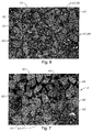
- 238000001000 micrograph Methods 0.000 description 3
- 239000000203 mixture Substances 0.000 description 3
- ORQBXQOJMQIAOY-UHFFFAOYSA-N nobelium Chemical compound [No] ORQBXQOJMQIAOY-UHFFFAOYSA-N 0.000 description 3
- 239000000843 powder Substances 0.000 description 3
- 238000012545 processing Methods 0.000 description 3
- VEXZGXHMUGYJMC-UHFFFAOYSA-N Hydrochloric acid Chemical compound Cl VEXZGXHMUGYJMC-UHFFFAOYSA-N 0.000 description 2
- PXHVJJICTQNCMI-UHFFFAOYSA-N Nickel Chemical compound [Ni] PXHVJJICTQNCMI-UHFFFAOYSA-N 0.000 description 2
- 238000013459 approach Methods 0.000 description 2
- 229910052788 barium Inorganic materials 0.000 description 2
- 238000005219 brazing Methods 0.000 description 2
- 229910052791 calcium Inorganic materials 0.000 description 2
- 238000003776 cleavage reaction Methods 0.000 description 2
- 239000002131 composite material Substances 0.000 description 2
- 238000010276 construction Methods 0.000 description 2
- 230000002939 deleterious effect Effects 0.000 description 2
- 230000003628 erosive effect Effects 0.000 description 2
- 238000005530 etching Methods 0.000 description 2
- 229910021472 group 8 element Inorganic materials 0.000 description 2
- 229910052749 magnesium Inorganic materials 0.000 description 2
- 229910052751 metal Inorganic materials 0.000 description 2
- 239000002184 metal Substances 0.000 description 2
- 239000007769 metal material Substances 0.000 description 2
- 230000035515 penetration Effects 0.000 description 2
- 230000002093 peripheral effect Effects 0.000 description 2
- 230000007017 scission Effects 0.000 description 2
- 229910052712 strontium Inorganic materials 0.000 description 2
- 230000007704 transition Effects 0.000 description 2
- 238000003466 welding Methods 0.000 description 2
- OKTJSMMVPCPJKN-UHFFFAOYSA-N Carbon Chemical compound [C] OKTJSMMVPCPJKN-UHFFFAOYSA-N 0.000 description 1
- CWYNVVGOOAEACU-UHFFFAOYSA-N Fe2+ Chemical compound [Fe+2] CWYNVVGOOAEACU-UHFFFAOYSA-N 0.000 description 1
- 230000004913 activation Effects 0.000 description 1
- 239000000853 adhesive Substances 0.000 description 1
- 230000001070 adhesive effect Effects 0.000 description 1
- 239000000956 alloy Substances 0.000 description 1
- 229910045601 alloy Inorganic materials 0.000 description 1
- 238000005275 alloying Methods 0.000 description 1
- 230000003466 anti-cipated effect Effects 0.000 description 1
- 239000010426 asphalt Substances 0.000 description 1
- 239000006227 byproduct Substances 0.000 description 1
- 229910052799 carbon Inorganic materials 0.000 description 1
- 239000003575 carbonaceous material Substances 0.000 description 1
- 150000001868 cobalt Chemical class 0.000 description 1
- 238000005336 cracking Methods 0.000 description 1
- 230000003247 decreasing effect Effects 0.000 description 1
- 230000009977 dual effect Effects 0.000 description 1
- 238000007730 finishing process Methods 0.000 description 1
- 238000003780 insertion Methods 0.000 description 1
- 230000037431 insertion Effects 0.000 description 1
- 230000003993 interaction Effects 0.000 description 1
- 229910052742 iron Inorganic materials 0.000 description 1
- 238000009533 lab test Methods 0.000 description 1
- 238000011068 loading method Methods 0.000 description 1
- 230000007246 mechanism Effects 0.000 description 1
- 238000012986 modification Methods 0.000 description 1
- 230000004048 modification Effects 0.000 description 1
- 229910052759 nickel Inorganic materials 0.000 description 1
- HBMJWWWQQXIZIP-UHFFFAOYSA-N silicon carbide Chemical compound [Si+]#[C-] HBMJWWWQQXIZIP-UHFFFAOYSA-N 0.000 description 1
- 229910010271 silicon carbide Inorganic materials 0.000 description 1
- 239000004575 stone Substances 0.000 description 1
- 238000003786 synthesis reaction Methods 0.000 description 1
- 239000002470 thermal conductor Substances 0.000 description 1
- 238000007669 thermal treatment Methods 0.000 description 1
- 238000012546 transfer Methods 0.000 description 1
- 239000002023 wood Substances 0.000 description 1
Images


Classifications
-
- B—PERFORMING OPERATIONS; TRANSPORTING
- B22—CASTING; POWDER METALLURGY
- B22F—WORKING METALLIC POWDER; MANUFACTURE OF ARTICLES FROM METALLIC POWDER; MAKING METALLIC POWDER; APPARATUS OR DEVICES SPECIALLY ADAPTED FOR METALLIC POWDER
- B22F7/00—Manufacture of composite layers, workpieces, or articles, comprising metallic powder, by sintering the powder, with or without compacting wherein at least one part is obtained by sintering or compression
- B22F7/06—Manufacture of composite layers, workpieces, or articles, comprising metallic powder, by sintering the powder, with or without compacting wherein at least one part is obtained by sintering or compression of composite workpieces or articles from parts, e.g. to form tipped tools
-
- B—PERFORMING OPERATIONS; TRANSPORTING
- B23—MACHINE TOOLS; METAL-WORKING NOT OTHERWISE PROVIDED FOR
- B23B—TURNING; BORING
- B23B27/00—Tools for turning or boring machines; Tools of a similar kind in general; Accessories therefor
- B23B27/14—Cutting tools of which the bits or tips or cutting inserts are of special material
- B23B27/141—Specially shaped plate-like cutting inserts, i.e. length greater or equal to width, width greater than or equal to thickness
- B23B27/145—Specially shaped plate-like cutting inserts, i.e. length greater or equal to width, width greater than or equal to thickness characterised by having a special shape
-
- C—CHEMISTRY; METALLURGY
- C04—CEMENTS; CONCRETE; ARTIFICIAL STONE; CERAMICS; REFRACTORIES
- C04B—LIME, MAGNESIA; SLAG; CEMENTS; COMPOSITIONS THEREOF, e.g. MORTARS, CONCRETE OR LIKE BUILDING MATERIALS; ARTIFICIAL STONE; CERAMICS; REFRACTORIES; TREATMENT OF NATURAL STONE
- C04B35/00—Shaped ceramic products characterised by their composition; Ceramics compositions; Processing powders of inorganic compounds preparatory to the manufacturing of ceramic products
- C04B35/515—Shaped ceramic products characterised by their composition; Ceramics compositions; Processing powders of inorganic compounds preparatory to the manufacturing of ceramic products based on non-oxide ceramics
- C04B35/52—Shaped ceramic products characterised by their composition; Ceramics compositions; Processing powders of inorganic compounds preparatory to the manufacturing of ceramic products based on non-oxide ceramics based on carbon, e.g. graphite
-
- C—CHEMISTRY; METALLURGY
- C04—CEMENTS; CONCRETE; ARTIFICIAL STONE; CERAMICS; REFRACTORIES
- C04B—LIME, MAGNESIA; SLAG; CEMENTS; COMPOSITIONS THEREOF, e.g. MORTARS, CONCRETE OR LIKE BUILDING MATERIALS; ARTIFICIAL STONE; CERAMICS; REFRACTORIES; TREATMENT OF NATURAL STONE
- C04B35/00—Shaped ceramic products characterised by their composition; Ceramics compositions; Processing powders of inorganic compounds preparatory to the manufacturing of ceramic products
- C04B35/622—Forming processes; Processing powders of inorganic compounds preparatory to the manufacturing of ceramic products
- C04B35/64—Burning or sintering processes
- C04B35/645—Pressure sintering
-
- C—CHEMISTRY; METALLURGY
- C04—CEMENTS; CONCRETE; ARTIFICIAL STONE; CERAMICS; REFRACTORIES
- C04B—LIME, MAGNESIA; SLAG; CEMENTS; COMPOSITIONS THEREOF, e.g. MORTARS, CONCRETE OR LIKE BUILDING MATERIALS; ARTIFICIAL STONE; CERAMICS; REFRACTORIES; TREATMENT OF NATURAL STONE
- C04B37/00—Joining burned ceramic articles with other burned ceramic articles or other articles by heating
- C04B37/02—Joining burned ceramic articles with other burned ceramic articles or other articles by heating with metallic articles
- C04B37/021—Joining burned ceramic articles with other burned ceramic articles or other articles by heating with metallic articles in a direct manner, e.g. direct copper bonding [DCB]
-
- C—CHEMISTRY; METALLURGY
- C04—CEMENTS; CONCRETE; ARTIFICIAL STONE; CERAMICS; REFRACTORIES
- C04B—LIME, MAGNESIA; SLAG; CEMENTS; COMPOSITIONS THEREOF, e.g. MORTARS, CONCRETE OR LIKE BUILDING MATERIALS; ARTIFICIAL STONE; CERAMICS; REFRACTORIES; TREATMENT OF NATURAL STONE
- C04B41/00—After-treatment of mortars, concrete, artificial stone or ceramics; Treatment of natural stone
- C04B41/009—After-treatment of mortars, concrete, artificial stone or ceramics; Treatment of natural stone characterised by the material treated
-
- C—CHEMISTRY; METALLURGY
- C04—CEMENTS; CONCRETE; ARTIFICIAL STONE; CERAMICS; REFRACTORIES
- C04B—LIME, MAGNESIA; SLAG; CEMENTS; COMPOSITIONS THEREOF, e.g. MORTARS, CONCRETE OR LIKE BUILDING MATERIALS; ARTIFICIAL STONE; CERAMICS; REFRACTORIES; TREATMENT OF NATURAL STONE
- C04B41/00—After-treatment of mortars, concrete, artificial stone or ceramics; Treatment of natural stone
- C04B41/45—Coating or impregnating, e.g. injection in masonry, partial coating of green or fired ceramics, organic coating compositions for adhering together two concrete elements
- C04B41/459—Temporary coatings or impregnations
-
- C—CHEMISTRY; METALLURGY
- C04—CEMENTS; CONCRETE; ARTIFICIAL STONE; CERAMICS; REFRACTORIES
- C04B—LIME, MAGNESIA; SLAG; CEMENTS; COMPOSITIONS THEREOF, e.g. MORTARS, CONCRETE OR LIKE BUILDING MATERIALS; ARTIFICIAL STONE; CERAMICS; REFRACTORIES; TREATMENT OF NATURAL STONE
- C04B41/00—After-treatment of mortars, concrete, artificial stone or ceramics; Treatment of natural stone
- C04B41/53—After-treatment of mortars, concrete, artificial stone or ceramics; Treatment of natural stone involving the removal of at least part of the materials of the treated article, e.g. etching, drying of hardened concrete
-
- C—CHEMISTRY; METALLURGY
- C04—CEMENTS; CONCRETE; ARTIFICIAL STONE; CERAMICS; REFRACTORIES
- C04B—LIME, MAGNESIA; SLAG; CEMENTS; COMPOSITIONS THEREOF, e.g. MORTARS, CONCRETE OR LIKE BUILDING MATERIALS; ARTIFICIAL STONE; CERAMICS; REFRACTORIES; TREATMENT OF NATURAL STONE
- C04B41/00—After-treatment of mortars, concrete, artificial stone or ceramics; Treatment of natural stone
- C04B41/80—After-treatment of mortars, concrete, artificial stone or ceramics; Treatment of natural stone of only ceramics
- C04B41/81—Coating or impregnation
-
- C—CHEMISTRY; METALLURGY
- C04—CEMENTS; CONCRETE; ARTIFICIAL STONE; CERAMICS; REFRACTORIES
- C04B—LIME, MAGNESIA; SLAG; CEMENTS; COMPOSITIONS THEREOF, e.g. MORTARS, CONCRETE OR LIKE BUILDING MATERIALS; ARTIFICIAL STONE; CERAMICS; REFRACTORIES; TREATMENT OF NATURAL STONE
- C04B41/00—After-treatment of mortars, concrete, artificial stone or ceramics; Treatment of natural stone
- C04B41/80—After-treatment of mortars, concrete, artificial stone or ceramics; Treatment of natural stone of only ceramics
- C04B41/91—After-treatment of mortars, concrete, artificial stone or ceramics; Treatment of natural stone of only ceramics involving the removal of part of the materials of the treated articles, e.g. etching
-
- E—FIXED CONSTRUCTIONS
- E21—EARTH DRILLING; MINING
- E21B—EARTH DRILLING, e.g. DEEP DRILLING; OBTAINING OIL, GAS, WATER, SOLUBLE OR MELTABLE MATERIALS OR A SLURRY OF MINERALS FROM WELLS
- E21B10/00—Drill bits
- E21B10/006—Drill bits providing a cutting edge which is self-renewable during drilling
-
- E—FIXED CONSTRUCTIONS
- E21—EARTH DRILLING; MINING
- E21B—EARTH DRILLING, e.g. DEEP DRILLING; OBTAINING OIL, GAS, WATER, SOLUBLE OR MELTABLE MATERIALS OR A SLURRY OF MINERALS FROM WELLS
- E21B10/00—Drill bits
- E21B10/46—Drill bits characterised by wear resisting parts, e.g. diamond inserts
- E21B10/56—Button-type inserts
- E21B10/567—Button-type inserts with preformed cutting elements mounted on a distinct support, e.g. polycrystalline inserts
- E21B10/5671—Button-type inserts with preformed cutting elements mounted on a distinct support, e.g. polycrystalline inserts with chip breaking arrangements
-
- E—FIXED CONSTRUCTIONS
- E21—EARTH DRILLING; MINING
- E21B—EARTH DRILLING, e.g. DEEP DRILLING; OBTAINING OIL, GAS, WATER, SOLUBLE OR MELTABLE MATERIALS OR A SLURRY OF MINERALS FROM WELLS
- E21B10/00—Drill bits
- E21B10/46—Drill bits characterised by wear resisting parts, e.g. diamond inserts
- E21B10/56—Button-type inserts
- E21B10/567—Button-type inserts with preformed cutting elements mounted on a distinct support, e.g. polycrystalline inserts
- E21B10/5673—Button-type inserts with preformed cutting elements mounted on a distinct support, e.g. polycrystalline inserts having a non planar or non circular cutting face
-
- E—FIXED CONSTRUCTIONS
- E21—EARTH DRILLING; MINING
- E21B—EARTH DRILLING, e.g. DEEP DRILLING; OBTAINING OIL, GAS, WATER, SOLUBLE OR MELTABLE MATERIALS OR A SLURRY OF MINERALS FROM WELLS
- E21B10/00—Drill bits
- E21B10/46—Drill bits characterised by wear resisting parts, e.g. diamond inserts
- E21B10/56—Button-type inserts
- E21B10/567—Button-type inserts with preformed cutting elements mounted on a distinct support, e.g. polycrystalline inserts
- E21B10/5676—Button-type inserts with preformed cutting elements mounted on a distinct support, e.g. polycrystalline inserts having a cutting face with different segments, e.g. mosaic-type inserts
-
- E—FIXED CONSTRUCTIONS
- E21—EARTH DRILLING; MINING
- E21B—EARTH DRILLING, e.g. DEEP DRILLING; OBTAINING OIL, GAS, WATER, SOLUBLE OR MELTABLE MATERIALS OR A SLURRY OF MINERALS FROM WELLS
- E21B10/00—Drill bits
- E21B10/46—Drill bits characterised by wear resisting parts, e.g. diamond inserts
- E21B10/56—Button-type inserts
- E21B10/567—Button-type inserts with preformed cutting elements mounted on a distinct support, e.g. polycrystalline inserts
- E21B10/573—Button-type inserts with preformed cutting elements mounted on a distinct support, e.g. polycrystalline inserts characterised by support details, e.g. the substrate construction or the interface between the substrate and the cutting element
- E21B10/5735—Interface between the substrate and the cutting element
-
- E—FIXED CONSTRUCTIONS
- E21—EARTH DRILLING; MINING
- E21B—EARTH DRILLING, e.g. DEEP DRILLING; OBTAINING OIL, GAS, WATER, SOLUBLE OR MELTABLE MATERIALS OR A SLURRY OF MINERALS FROM WELLS
- E21B10/00—Drill bits
- E21B10/60—Drill bits characterised by conduits or nozzles for drilling fluids
- E21B10/602—Drill bits characterised by conduits or nozzles for drilling fluids the bit being a rotary drag type bit with blades
-
- E—FIXED CONSTRUCTIONS
- E21—EARTH DRILLING; MINING
- E21B—EARTH DRILLING, e.g. DEEP DRILLING; OBTAINING OIL, GAS, WATER, SOLUBLE OR MELTABLE MATERIALS OR A SLURRY OF MINERALS FROM WELLS
- E21B10/00—Drill bits
- E21B10/62—Drill bits characterised by parts, e.g. cutting elements, which are detachable or adjustable
- E21B10/627—Drill bits characterised by parts, e.g. cutting elements, which are detachable or adjustable with plural detachable cutting elements
- E21B10/633—Drill bits characterised by parts, e.g. cutting elements, which are detachable or adjustable with plural detachable cutting elements independently detachable
-
- B—PERFORMING OPERATIONS; TRANSPORTING
- B22—CASTING; POWDER METALLURGY
- B22F—WORKING METALLIC POWDER; MANUFACTURE OF ARTICLES FROM METALLIC POWDER; MAKING METALLIC POWDER; APPARATUS OR DEVICES SPECIALLY ADAPTED FOR METALLIC POWDER
- B22F3/00—Manufacture of workpieces or articles from metallic powder characterised by the manner of compacting or sintering; Apparatus specially adapted therefor ; Presses and furnaces
- B22F3/24—After-treatment of workpieces or articles
- B22F2003/241—Chemical after-treatment on the surface
- B22F2003/244—Leaching
-
- B—PERFORMING OPERATIONS; TRANSPORTING
- B22—CASTING; POWDER METALLURGY
- B22F—WORKING METALLIC POWDER; MANUFACTURE OF ARTICLES FROM METALLIC POWDER; MAKING METALLIC POWDER; APPARATUS OR DEVICES SPECIALLY ADAPTED FOR METALLIC POWDER
- B22F5/00—Manufacture of workpieces or articles from metallic powder characterised by the special shape of the product
- B22F2005/001—Cutting tools, earth boring or grinding tool other than table ware
-
- B—PERFORMING OPERATIONS; TRANSPORTING
- B22—CASTING; POWDER METALLURGY
- B22F—WORKING METALLIC POWDER; MANUFACTURE OF ARTICLES FROM METALLIC POWDER; MAKING METALLIC POWDER; APPARATUS OR DEVICES SPECIALLY ADAPTED FOR METALLIC POWDER
- B22F2998/00—Supplementary information concerning processes or compositions relating to powder metallurgy
-
- B—PERFORMING OPERATIONS; TRANSPORTING
- B22—CASTING; POWDER METALLURGY
- B22F—WORKING METALLIC POWDER; MANUFACTURE OF ARTICLES FROM METALLIC POWDER; MAKING METALLIC POWDER; APPARATUS OR DEVICES SPECIALLY ADAPTED FOR METALLIC POWDER
- B22F2999/00—Aspects linked to processes or compositions used in powder metallurgy
-
- C—CHEMISTRY; METALLURGY
- C04—CEMENTS; CONCRETE; ARTIFICIAL STONE; CERAMICS; REFRACTORIES
- C04B—LIME, MAGNESIA; SLAG; CEMENTS; COMPOSITIONS THEREOF, e.g. MORTARS, CONCRETE OR LIKE BUILDING MATERIALS; ARTIFICIAL STONE; CERAMICS; REFRACTORIES; TREATMENT OF NATURAL STONE
- C04B2235/00—Aspects relating to ceramic starting mixtures or sintered ceramic products
- C04B2235/02—Composition of constituents of the starting material or of secondary phases of the final product
- C04B2235/30—Constituents and secondary phases not being of a fibrous nature
- C04B2235/32—Metal oxides, mixed metal oxides, or oxide-forming salts thereof, e.g. carbonates, nitrates, (oxy)hydroxides, chlorides
- C04B2235/3205—Alkaline earth oxides or oxide forming salts thereof, e.g. beryllium oxide
- C04B2235/3206—Magnesium oxides or oxide-forming salts thereof
-
- C—CHEMISTRY; METALLURGY
- C04—CEMENTS; CONCRETE; ARTIFICIAL STONE; CERAMICS; REFRACTORIES
- C04B—LIME, MAGNESIA; SLAG; CEMENTS; COMPOSITIONS THEREOF, e.g. MORTARS, CONCRETE OR LIKE BUILDING MATERIALS; ARTIFICIAL STONE; CERAMICS; REFRACTORIES; TREATMENT OF NATURAL STONE
- C04B2235/00—Aspects relating to ceramic starting mixtures or sintered ceramic products
- C04B2235/02—Composition of constituents of the starting material or of secondary phases of the final product
- C04B2235/30—Constituents and secondary phases not being of a fibrous nature
- C04B2235/32—Metal oxides, mixed metal oxides, or oxide-forming salts thereof, e.g. carbonates, nitrates, (oxy)hydroxides, chlorides
- C04B2235/3205—Alkaline earth oxides or oxide forming salts thereof, e.g. beryllium oxide
- C04B2235/3208—Calcium oxide or oxide-forming salts thereof, e.g. lime
-
- C—CHEMISTRY; METALLURGY
- C04—CEMENTS; CONCRETE; ARTIFICIAL STONE; CERAMICS; REFRACTORIES
- C04B—LIME, MAGNESIA; SLAG; CEMENTS; COMPOSITIONS THEREOF, e.g. MORTARS, CONCRETE OR LIKE BUILDING MATERIALS; ARTIFICIAL STONE; CERAMICS; REFRACTORIES; TREATMENT OF NATURAL STONE
- C04B2235/00—Aspects relating to ceramic starting mixtures or sintered ceramic products
- C04B2235/02—Composition of constituents of the starting material or of secondary phases of the final product
- C04B2235/30—Constituents and secondary phases not being of a fibrous nature
- C04B2235/32—Metal oxides, mixed metal oxides, or oxide-forming salts thereof, e.g. carbonates, nitrates, (oxy)hydroxides, chlorides
- C04B2235/3205—Alkaline earth oxides or oxide forming salts thereof, e.g. beryllium oxide
- C04B2235/3213—Strontium oxides or oxide-forming salts thereof
-
- C—CHEMISTRY; METALLURGY
- C04—CEMENTS; CONCRETE; ARTIFICIAL STONE; CERAMICS; REFRACTORIES
- C04B—LIME, MAGNESIA; SLAG; CEMENTS; COMPOSITIONS THEREOF, e.g. MORTARS, CONCRETE OR LIKE BUILDING MATERIALS; ARTIFICIAL STONE; CERAMICS; REFRACTORIES; TREATMENT OF NATURAL STONE
- C04B2235/00—Aspects relating to ceramic starting mixtures or sintered ceramic products
- C04B2235/02—Composition of constituents of the starting material or of secondary phases of the final product
- C04B2235/30—Constituents and secondary phases not being of a fibrous nature
- C04B2235/32—Metal oxides, mixed metal oxides, or oxide-forming salts thereof, e.g. carbonates, nitrates, (oxy)hydroxides, chlorides
- C04B2235/3205—Alkaline earth oxides or oxide forming salts thereof, e.g. beryllium oxide
- C04B2235/3215—Barium oxides or oxide-forming salts thereof
-
- C—CHEMISTRY; METALLURGY
- C04—CEMENTS; CONCRETE; ARTIFICIAL STONE; CERAMICS; REFRACTORIES
- C04B—LIME, MAGNESIA; SLAG; CEMENTS; COMPOSITIONS THEREOF, e.g. MORTARS, CONCRETE OR LIKE BUILDING MATERIALS; ARTIFICIAL STONE; CERAMICS; REFRACTORIES; TREATMENT OF NATURAL STONE
- C04B2235/00—Aspects relating to ceramic starting mixtures or sintered ceramic products
- C04B2235/02—Composition of constituents of the starting material or of secondary phases of the final product
- C04B2235/30—Constituents and secondary phases not being of a fibrous nature
- C04B2235/40—Metallic constituents or additives not added as binding phase
- C04B2235/405—Iron group metals
-
- C—CHEMISTRY; METALLURGY
- C04—CEMENTS; CONCRETE; ARTIFICIAL STONE; CERAMICS; REFRACTORIES
- C04B—LIME, MAGNESIA; SLAG; CEMENTS; COMPOSITIONS THEREOF, e.g. MORTARS, CONCRETE OR LIKE BUILDING MATERIALS; ARTIFICIAL STONE; CERAMICS; REFRACTORIES; TREATMENT OF NATURAL STONE
- C04B2235/00—Aspects relating to ceramic starting mixtures or sintered ceramic products
- C04B2235/02—Composition of constituents of the starting material or of secondary phases of the final product
- C04B2235/30—Constituents and secondary phases not being of a fibrous nature
- C04B2235/42—Non metallic elements added as constituents or additives, e.g. sulfur, phosphor, selenium or tellurium
- C04B2235/422—Carbon
- C04B2235/427—Diamond
-
- C—CHEMISTRY; METALLURGY
- C04—CEMENTS; CONCRETE; ARTIFICIAL STONE; CERAMICS; REFRACTORIES
- C04B—LIME, MAGNESIA; SLAG; CEMENTS; COMPOSITIONS THEREOF, e.g. MORTARS, CONCRETE OR LIKE BUILDING MATERIALS; ARTIFICIAL STONE; CERAMICS; REFRACTORIES; TREATMENT OF NATURAL STONE
- C04B2235/00—Aspects relating to ceramic starting mixtures or sintered ceramic products
- C04B2235/02—Composition of constituents of the starting material or of secondary phases of the final product
- C04B2235/30—Constituents and secondary phases not being of a fibrous nature
- C04B2235/44—Metal salt constituents or additives chosen for the nature of the anions, e.g. hydrides or acetylacetonate
- C04B2235/442—Carbonates
-
- C—CHEMISTRY; METALLURGY
- C04—CEMENTS; CONCRETE; ARTIFICIAL STONE; CERAMICS; REFRACTORIES
- C04B—LIME, MAGNESIA; SLAG; CEMENTS; COMPOSITIONS THEREOF, e.g. MORTARS, CONCRETE OR LIKE BUILDING MATERIALS; ARTIFICIAL STONE; CERAMICS; REFRACTORIES; TREATMENT OF NATURAL STONE
- C04B2235/00—Aspects relating to ceramic starting mixtures or sintered ceramic products
- C04B2235/02—Composition of constituents of the starting material or of secondary phases of the final product
- C04B2235/50—Constituents or additives of the starting mixture chosen for their shape or used because of their shape or their physical appearance
- C04B2235/54—Particle size related information
- C04B2235/5418—Particle size related information expressed by the size of the particles or aggregates thereof
- C04B2235/5436—Particle size related information expressed by the size of the particles or aggregates thereof micrometer sized, i.e. from 1 to 100 micron
-
- C—CHEMISTRY; METALLURGY
- C04—CEMENTS; CONCRETE; ARTIFICIAL STONE; CERAMICS; REFRACTORIES
- C04B—LIME, MAGNESIA; SLAG; CEMENTS; COMPOSITIONS THEREOF, e.g. MORTARS, CONCRETE OR LIKE BUILDING MATERIALS; ARTIFICIAL STONE; CERAMICS; REFRACTORIES; TREATMENT OF NATURAL STONE
- C04B2235/00—Aspects relating to ceramic starting mixtures or sintered ceramic products
- C04B2235/02—Composition of constituents of the starting material or of secondary phases of the final product
- C04B2235/50—Constituents or additives of the starting mixture chosen for their shape or used because of their shape or their physical appearance
- C04B2235/54—Particle size related information
- C04B2235/5463—Particle size distributions
- C04B2235/5472—Bimodal, multi-modal or multi-fraction
-
- C—CHEMISTRY; METALLURGY
- C04—CEMENTS; CONCRETE; ARTIFICIAL STONE; CERAMICS; REFRACTORIES
- C04B—LIME, MAGNESIA; SLAG; CEMENTS; COMPOSITIONS THEREOF, e.g. MORTARS, CONCRETE OR LIKE BUILDING MATERIALS; ARTIFICIAL STONE; CERAMICS; REFRACTORIES; TREATMENT OF NATURAL STONE
- C04B2237/00—Aspects relating to ceramic laminates or to joining of ceramic articles with other articles by heating
- C04B2237/30—Composition of layers of ceramic laminates or of ceramic or metallic articles to be joined by heating, e.g. Si substrates
- C04B2237/32—Ceramic
- C04B2237/36—Non-oxidic
- C04B2237/363—Carbon
-
- C—CHEMISTRY; METALLURGY
- C04—CEMENTS; CONCRETE; ARTIFICIAL STONE; CERAMICS; REFRACTORIES
- C04B—LIME, MAGNESIA; SLAG; CEMENTS; COMPOSITIONS THEREOF, e.g. MORTARS, CONCRETE OR LIKE BUILDING MATERIALS; ARTIFICIAL STONE; CERAMICS; REFRACTORIES; TREATMENT OF NATURAL STONE
- C04B2237/00—Aspects relating to ceramic laminates or to joining of ceramic articles with other articles by heating
- C04B2237/30—Composition of layers of ceramic laminates or of ceramic or metallic articles to be joined by heating, e.g. Si substrates
- C04B2237/40—Metallic
- C04B2237/401—Cermets
-
- C—CHEMISTRY; METALLURGY
- C04—CEMENTS; CONCRETE; ARTIFICIAL STONE; CERAMICS; REFRACTORIES
- C04B—LIME, MAGNESIA; SLAG; CEMENTS; COMPOSITIONS THEREOF, e.g. MORTARS, CONCRETE OR LIKE BUILDING MATERIALS; ARTIFICIAL STONE; CERAMICS; REFRACTORIES; TREATMENT OF NATURAL STONE
- C04B2237/00—Aspects relating to ceramic laminates or to joining of ceramic articles with other articles by heating
- C04B2237/50—Processing aspects relating to ceramic laminates or to the joining of ceramic articles with other articles by heating
- C04B2237/61—Joining two substrates of which at least one is porous by infiltrating the porous substrate with a liquid, such as a molten metal, causing bonding of the two substrates, e.g. joining two porous carbon substrates by infiltrating with molten silicon
-
- C—CHEMISTRY; METALLURGY
- C04—CEMENTS; CONCRETE; ARTIFICIAL STONE; CERAMICS; REFRACTORIES
- C04B—LIME, MAGNESIA; SLAG; CEMENTS; COMPOSITIONS THEREOF, e.g. MORTARS, CONCRETE OR LIKE BUILDING MATERIALS; ARTIFICIAL STONE; CERAMICS; REFRACTORIES; TREATMENT OF NATURAL STONE
- C04B2237/00—Aspects relating to ceramic laminates or to joining of ceramic articles with other articles by heating
- C04B2237/50—Processing aspects relating to ceramic laminates or to the joining of ceramic articles with other articles by heating
- C04B2237/76—Forming laminates or joined articles comprising at least one member in the form other than a sheet or disc, e.g. two tubes or a tube and a sheet or disc
- C04B2237/765—Forming laminates or joined articles comprising at least one member in the form other than a sheet or disc, e.g. two tubes or a tube and a sheet or disc at least one member being a tube
Definitions
- the invention relates to superhard polycrystalline material elements for wear, cutting, drawing, and other applications where engineered superhard surfaces are needed.
- the invention particularly relates to polycrystalline diamond and polycrystalline diamond-like (collectively called PCD) elements with greatly improved wear resistance and methods of manufacturing them.
- PCD elements Polycrystalline diamond and polycrystalline diamond-like elements are known, for the purposes of this specification, as PCD elements.
- PCD elements are formed from carbon based materials with exceptionally short inter-atomic distances between neighboring atoms.
- One type of diamond-like material similar to PCD is known as carbonitride (CN) described in U.S Patent No. 5,776,615.
- CN carbonitride
- PCD elements are formed from a mix of materials processed under high-temperature and high-pressure into a polycrystalline matrix of inter-bonded superhard carbon based crystals.
- a common trait of PCD elements is the use of catalyzing materials during their formation, the residue from which, often imposes a limit upon the maximum useful operating temperature of the element while in service.
- PCD element A well known, manufactured form of PCD element is a two-layer or multi-layer PCD element where a facing table of polycrystalline diamond is integrally bonded to a substrate of less hard material, such as tungsten carbide.
- the PCD element may be in the form of a circular or part-circular tablet, or may be formed into other shapes, suitable for applications such as hollow dies, heat sinks, friction bearings, valve surfaces, indentors, tool mandrels, etc. PCD elements of this type may be used in almost any application where a hard wear and erosion resistant material is required.
- the substrate of the PCD element may be brazed to a carrier, often also of cemented tungsten carbide.
- PCD's used as cutting elements, for example in fixed cutter or rolling cutter earth boring bits when received in a socket of the drill bit, or when fixed to a post in a machine tool for machining.
- PCD elements are typically called polycrystalline diamond cutters (PDC).
- PCD element is a unitary PCD element without an integral substrate where a table of polycrystalline diamond is fixed to a tool or wear surface by mechanical means or a bonding process.
- These PCD elements differ from those above in that diamond particles are present throughout the element.
- These PCD elements may be held in place mechanically, they may be embedded within a larger PCD element that has a substrate, or, alternately, they may be fabricated with a metallic layer which may be bonded with a brazing or welding process.
- a plurality of these PCD elements may be made from a single PCD, as shown, for example, in U.S. Patent Numbers 4,481,016 and 4,525,179 herein incorporated by reference for all they disclose.
- PCD elements are most often formed by sintering diamond powder with a suitable binder-catalyzing material in a high-pressure, high-temperature press.
- a suitable binder-catalyzing material in a high-pressure, high-temperature press.
- One particular method of forming this polycrystalline diamond is disclosed in U.S. Patent No. 3,141,746 herein incorporated by reference for all it discloses.
- diamond powder is applied to the surface of a preformed tungsten carbide substrate incorporating cobalt. The assembly is then subjected to very high temperature and pressure in a press.
- cobalt migrates from the substrate into the diamond layer and acts as a binder-catalyzing material, causing the diamond particles to bond to one another with diamond-to-diamond bonding, and also causing the diamond layer to bond to the substrate.
- the completed PCD element has at least one body with a matrix of diamond crystals bonded to each other with many interstices containing a binder-catalyzing material as described above.
- the diamond crystals comprise a first continuous matrix of diamond, and the interstices form a second continuous matrix of interstices containing the binder-catalyzing material.
- the diamond body constitutes 85% to 95% by volume and the binder-catalyzing material the other 5% to 15%.
- Such an element may be subject to thermal degradation due to differential thermal expansion between the interstitial cobalt binder-catalyzing material and diamond matrix beginning at temperatures of about 400 degrees C. Upon sufficient expansion the diamond-to-diamond bonding may be ruptured and cracks and chips may occur.
- the presence of the binder-catalyzing material in the interstitial regions adhering to the diamond crystals of the diamond matrix leads to another form of thermal degradation. Due to the presence of the binder-catalyzing material, the diamond is caused to graphitize as temperature increases, typically limiting the operation temperature to about 750 degrees C.
- cobalt is most commonly used as the binder-catalyzing material
- any group VIII element including cobalt, nickel, iron, and alloys thereof, may be employed.
- thermally stable polycrystalline diamond components have been produced as preform PCD elements for cutting and/or wear resistant elements, as disclosed in U.S. Patent No. 4,224,380 herein incorporated by reference for all it discloses.
- the cobalt or other binder-catalyzing material in conventional polycrystalline diamond is leached out from the continuous interstitial matrix after formation.
- Numerous methods for leaching the binder-catalyzing material are known. Some leaching methods are disclosed, for example, in U.S. Patent Nos. 4,572,722 and 4,797,241 both herein incorporated by reference for all they disclose.
- leaching the binder-catalyzing material may increase the temperature resistance of the diamond to about 1200 degrees C, the leaching process also removes the cemented carbide substrate. In addition, because there is no integral substrate or other bondable surface, there are severe difficulties in mounting such material for use in operation.
- the fabrication methods for this 'thermally stable' PCD element typically produce relatively low diamond volume densities, typically of the order of 80 volume % or less.
- This low diamond volume density enables a thorough leaching process, but the resulting finished part is typically relatively weak in impact strength.
- the low volume density is typically achieved by using an admixtures process and using relatively small diamond crystals with average particle sizes of about 15 microns or less. These small particles are typically coated with a catalyzing material prior to processing.
- the admixtures process causes the diamond particles to be widely spaced in the finished product and relatively small percentages of their outer surface areas dedicated to diamond-to-diamond bonding, often less than 50%, contributing to the low impact strengths.
- thermally stable polycrystalline diamond components In these so-called “thermally stable” polycrystalline diamond components, the lack of a suitable bondable substrate for later attachment to a work tool has been addressed by several methods.
- One such method to attach a bondable substrate to a "thermally stable" polycrystalline diamond preform is shown in U.S. Patent No. 4,944,772 herein incorporated by reference for all it discloses.
- a porous polycrystalline diamond preform is first manufactured, and then it is re-sintered in the presence of a catalyzing material at high-temperatures and pressures with a barrier layer of other material which, in theory, prevents the catalyzing material from re-infiltrating the porous polycrystalline diamond preform.
- the resulting product typically has an abrupt transition between the preform and the barrier layer, causing problematic stress concentrations in service. This product would be considered to be more a joined composite than an integral body.
- thermally stable polycrystalline diamond silicon is used as the catalyzing material.
- the process for making polycrystalline diamond with a silicon catalyzing material is quite similar to that described above, except that at synthesis temperatures and pressures, most of the silicon is reacted to form silicon carbide, which is not an effective catalyzing material.
- the thermal resistance is somewhat improved, but thermal degradation still occurs due to some residual silicon remaining, generally uniformly distributed in the interstices of the interstitial matrix. Again, there are mounting problems with this type of PCD element because there is no bondable surface.
- PCD carbonates
- Mg, Ca, Sr, and Ba carbonates
- PCD of this type typically has greater wear-resistance and hardness than the previous types of PCD elements.
- the material is difficult to produce on a commercial scale since much higher pressures are required for sintering than is the case with conventional and thermally stable polycrystalline diamond.
- thermal degradation may still occur due to the residual binder-catalyzing material remaining in the interstices. Again, because there is no integral substrate or other bondable surface, there are difficulties in mounting this material to a working surface.
- PVD physical vapor deposition
- CVD chemical vapor deposition
- PVD and/or CVD processes to coat surfaces with diamond or diamond like coatings may be used, for example, to provide a closely packed set of epitaxially oriented crystals of diamond or other superhard crystals on a surface.
- these materials have very high diamond densities because they are so closely packed, there is no significant amount of diamond to diamond bonding between adjacent crystals, making them quite weak overall, and subject to fracture when high shear loads are applied.
- the result is that although these coatings have very high diamond densities, they tend to be mechanically weak, causing very poor impact toughness and abrasion resistance when used in highly loaded applications such as with cutting elements, bearing devices, wear elements, and dies.
- the present invention provides a superhard polycrystalline diamond or diamond-like element with greatly improved wear resistance without loss of impact strength.
- PCD elements for the purposes of this specification, these elements are formed with a binder-catalyzing material in a high-temperature, high-pressure (HTHP) process.
- the PCD element has a plurality of partially bonded diamond or diamond-like crystals forming a continuous diamond matrix body with a diamond volume density greater than 85%. Interstices among the diamond crystals form a continuous interstitial matrix containing a catalyzing material.
- the diamond matrix table is formed and integrally bonded to a substrate containing the catalyzing material during the HTHP process.
- the diamond matrix body has a working surface, where a portion of the interstitial matrix in the body adjacent to the working surface is substantially free of the catalyzing material, and the remaining interstitial matrix contains the catalyzing material. Typically, less than about 70% of the body of the diamond matrix table is free of the catalyzing material.
- the working surface that is substantially free of the catalyzing material is not subject to the thermal degradation encountered in the other areas of the working surface, resulting in improved wear resistance without loss of impact strength.
- the processed working surface may be a portion of the facing table of the body, a portion of the peripheral surface of the body, or portions of all these surfaces.
- the catalyzing material is cobalt or other iron group metal
- the method of depleting the catalyzing material is to leach it from the interstices near the surface of a PCD element in an acid etching process. It is anticipated that the method of removing the catalyzing material from the surface may also be by electrical discharge, or other electrical or galvanic process, or by evaporation.
- a further method of manufacture of a PCD element comprising a body integrally formed with a metallic substrate, the body comprising bonded diamond crystals and a catalyzing material is also disclosed.
- the treatment is performed by treating the body to render a volume thereof substantially free of the catalyzing material while permitting the catalyzing material to remain in at least some of the remaining volume of the body and while permitting the substrate to remain substantially unaffected when treating the body.
- the treatment provides an enhanced wear resistance to the treated portion of the element while maintaining the impact strength of the entire element substantially the same.
- an element having a body comprising a plurality of partially bonded diamond crystals, a catalyzing material and an interstitial matrix; the body having a working surface.
- the interstitial matrix in the body adjacent to the working surface is substantially free of the catalyzing material, and the remaining interstitial matrix contains the catalyzing material.
- the portion of the working surface that is substantially free of the catalyzing material has substantially the same impact strength as the remaining interstitial matrix.
- a PCD element is disclosed with a body having a catalyzing material, an interstitial matrix, and a working surface.
- the interstitial matrix in the body adjacent to the working surface is substantially free of the catalyzing material, and the remaining interstitial matrix contains the catalyzing material.
- a PCD element having a body with a working surface.
- a first volume of the body remote from the working surface contains a catalyzing material, and a second volume of the body adjacent to the working surface is substantially free of the catalyzing material.
- a PCD element comprising a diamond containing body integrally formed with a metallic substrate.
- the body has at least an 85% by volume diamond density and an interstitial matrix.
- the interstitial matrix in the body adjacent to a working surface is substantially free of the catalyzing material, and the interstitial regions where the body contacts the substrate contain the catalyzing material and have an average thickness greater than 0.15mm.
- a PCD element comprising a body of bonded diamonds integrally formed with a metallic substrate.
- the body has a working surface and at least an 85% by volume diamond density.
- a first volume of the body adjacent to the working surface contains a catalyzing material, and a second volume of the body adjacent to the working surface is substantially free of the catalyzing material.
- the first volume and the second volume have substantially the same impact strength.
- a PCD element comprising a diamond containing body integrally formed with a metallic substrate.
- the body having at least an 85% by volume diamond density and an interstitial matrix, a first portion of the interstitial matrix in the body adjacent to a working surface is substantially free of the catalyzing material, a second portion of the interstitial matrix in the body adjacent to a working surface contains the catalyzing material.
- the interstitial matrix where the body contacts the substrate contains the catalyzing material and has an average thickness greater than 0.15 mm.
- the first portion of the interstitial matrix and the second portion of the interstitial matrix have substantially the same impact strength.
- a preform cutting element has a body of a superhard polycrystalline material comprising a plurality of partially bonded superhard crystals integrally formed with a metallic substrate, a plurality of interstitial regions among the superhard crystals and a catalyzing material.
- the body has at least an 85% by volume diamond density and a cutting surface.
- the interstitial regions adjacent to at least a first portion of the cutting surface are substantially free of the catalyzing material, the interstitial regions adjacent to a second portion of the cutting surface contain the catalyzing material, and the interstitial regions where the body contacts the substrate contain the catalyzing material and have an average thickness greater than 0.15 mm.
- the first portion of the cutting surface and the second portion have substantially the same impact strength.
- the PCD elements of the present invention may be used for wear, cutting, drawing, and other applications where engineered diamond surfaces are needed. Specific applications are as cutting elements in rotary drill bits of both the fixed cutter type and the rolling cutter type, as hollow dies, heat sinks, friction bearings, valve surfaces, indentors, tool mandrels, etc.
- the PCD element of the present invention may be used to machine abrasive wood products, ferrous and nonferrous materials and also very hard or abrasive engineering materials such as stone and asphalt and the like.
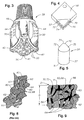
- the polycrystalline diamond or diamond-like material (PCD) element 2 of the present invention is shown in Figure 1A.
- the PCD element 2 has a plurality of partially bonded superhard, diamond or diamond-like, crystals 60, (shown in Figures 7 and 9) a catalyzing material 64, and an interstitial matrix 68 formed by the interstices 62 among the crystals 60.
- the element 2 also has one or more working surfaces 4 and the diamond crystals 60 and the interstices 62 form the volume of the body 8 of the PCD element 2.
- the element 2 is integrally formed with a metallic substrate 6, typically tungsten carbide with a cobalt binder material.
- the volume density of the diamond in the body 8 must be greater than 85 volume %, and preferably be higher than 90%.
- the working surface 4 is any portion of the PCD body 8 which, in operation, may contact the object to be worked. In this specification, when the working surface 4 is discussed, it is understood that it applies to any portion of the body 8 which may be exposed and/or used as a working surface. Furthermore, any portion of any of the working surface 4 is, in and of itself, a working surface.
- the interstices 62 among the crystals 60 fill with the catalyzing material 64 followed by bonds forming among the crystals 60.
- some of the catalyzing material 64 is selectively depleted from some of the interstices 62.
- a first volume of the body 8 of the PCD element 2 remote from the working surface 4 contains the catalyzing material 64, and a second volume of the body 8 adjacent to the working surface 4 is substantially free of the catalyzing material 64.
- the interstices 62 which are substantially free of the catalyzing material 64 are indicated by numeral 66.
- the interstitial matrix 68 of the body 8 adjacent to at least a portion of the working surface 4 is substantially free of the catalyzing material 64, and the remaining interstitial matrix 68 contains the catalyzing material 64.
- the PCD element 2 is preferably bonded in the HPHT process to a substrate 6 of less hard material, usually cemented tungsten carbide or other metallic material, but use of a substrate 6 is not required.
- the body adjacent to the working surface 4 is substantially free of the catalyzing material 64, the deleterious effects of the binder-catalyzing material 64 are substantially decreased, and thermal degradation of the working surface 4 due to the presence of the catalyzing material 64 is effectively eliminated.
- the result is a new PCD element 2 that has the enhanced thermal properties approximating that of the so called thermally stable PCD elements, while maintaining the toughness, convenience of manufacture, and bonding ability of the traditional PDC elements. This translates to higher wear resistance in cutting applications, higher heat transfer capacity in heat sink applications, higher load capacity in bearing applications, less surface distortion in valve applications, and has advantages in numerous other applications including hollow dies, indentors, tool mandrels, and wear elements. These benefits are gained without loss of impact strength in the elements. Details of specific applications of the new PCD element 2 will be discussed in more detail later in the specification.
- the interstitial spaces 62 among the crystals 60 become filled with a binder-catalyzing material 64. It is this catalyzing material 64 that allows the bonds to be formed between adjacent diamond crystals 60 at the relatively low pressures and temperatures present in the press.
- the prior art PCD element has at least one continuous matrix of crystals 60 bonded to each other with the many interstices 62 containing a binder-catalyzing material 64, typically cobalt or other group VIII element.
- the crystals 60 comprise a first continuous matrix of diamond, and the interstices 62 form a second continuous matrix known as the interstitial matrix 68, containing the binder-catalyzing material.
- the PCD element 2 may be formed in the same manner as the prior art PCD elements described above.
- the working surface 4, 70, 72 of the PCD element 2 is processed in a manner which removes a portion of the binder-catalyzing material from the adjacent body. The result is that the interstices 62 among the diamond crystals 60 adjacent to the working surface are substantially free of the catalyzing material 64 indicated by numeral 66.
- the portion of the working surface 4, 70, 72 that is free of the catalyzing material 64 is not subject to the thermal degradation encountered in the other areas of the PCD, resulting in improved thermal characteristics.
- the average diamond volume density in the body 8 of the PCD element 2 of the present invention ranges from about 85% to about 99%.
- the high diamond volume density is achieved by using diamond crystals 60 with a range of particle sizes, with an average particle size ranging from about 30 to about 60 microns.
- the diamond mixture may comprise 20% to 60% diamond crystals 60 in the 5-15 micron range, 20% to 40% diamond crystals 60 in the 25-40 micron range, and 20% to 40% diamond crystals 60 in the 50-80 micron diameter range, although numerous other size ranges and percentages may be used.
- This mixture of large and small diamond crystals 60 allows the diamond crystals 60 to have relatively high percentages of their outer surface areas dedicated to diamond-to-diamond bonding, often approaching 95%, contributing to a relatively high apparent abrasion resistance.
- the catalyzing material 64 is cobalt or other iron group material, and the method of removing the catalyzing material 64 is to leach it from the interstices 62 near the working surface 4, 70, 72 of a PCD element 2 in an acid etching process to a depth of greater than about 0.2 mm. It is also possible that the method of removing the catalyzing material 64 from near the surface may be by electrical discharge, or other electrical or galvanic process or by evaporation.
- the catalyzing material 64 is depleted by combining it chemically, such as alloying, with another material such that it no longer acts as a catalyzing material.
- a material may remain in the interstices among the diamond crystals 60, but that material no longer acts as a catalyzing material 64 - effectively removing it.
- the catalyzing material 64 is removed by causing it to transform into a material that no longer acts as a catalyzing material. This may be accomplished by a crystal structure change, phase change, mechanical 'working', thermal treatment or other treatment methods. This method may apply to non-metallic or non-reactive catalyzing materials. Again, a material may remain in the interstices 62 among the diamond crystals, but that material no longer acts as a catalyzing material 64 - effectively removing the catalyzing material.
- the PCD element 2 of the present invention is no longer susceptible to the type of thermal degradation known to occur in the prior art PCD elements.
- the first mode of thermal degradation begins at temperatures as low as about 400 degrees C and is due to differential thermal expansion between the catalyzing material 64 in the interstices 62 and the crystals 60. Upon sufficient expansion the diamond-to-diamond bonding may be ruptured and cracks and chips may occur.
- the second mode of thermal degradation begins at temperatures of about 750 degrees C. This mode is caused by the catalyzing ability of the binder-catalyzing material 64 contacting the crystals 60, and causing the crystals 60 to graphitize as the temperature exceeds about 750 degrees C. As the crystals 60 graphitize, they undergo a huge volume increase resulting in cracking and dis-bond from the body 4. Even a coating of a few microns of the catalyzing material 64 on the surfaces of the diamond crystals 60 can enable this mode of thermal degradation.
- the catalyzing material 64 must be removed both from the interstices 62 among the diamond crystals 60 and from the surfaces of the diamond crystals 60 as well. If the catalyzing material 64 is removed from both the surfaces of the diamond crystals 60 and from the interstices 62 the onset of thermal degradation for the diamond crystals 60 in that region would approach 1200 C.
- This dual degradation mode provides some unexpected benefits.
- this may be accomplished by changing the treatment process such that in areas requiring maximum wear resistance, the catalyzing material is depleted from both the interstices 62 and the surfaces of the diamond crystals 60.
- those areas would be treated so as to deplete the catalyzing material 64 primarily from the interstices 62, but allowing some, if not all, of the diamond crystals 60 to remain in contact with the catalyzing material.
- the PCD element 2, 50, 52 has a body 8 of bonded diamonds 60 integrally formed with a metallic substrate 32, 51.
- the body 8 has a working surface 70, 72 and at least an 85% by volume diamond density.
- a first volume of the body 8 adjacent to the working surface 70, 72 contains a catalyzing material, and a second volume of the body 8 adjacent to the working surface 70, 72 is substantially free of the catalyzing material.
- the first volume and the second volume have substantially the same impact strength.
- Figures 13-36 show some of configurations where this selective treatment is desirable for cutting elements, and will be described in more detail later.
- the depth of depletion of the catalyzing material 64 from the working surface 4 may vary depending upon the method used for depleting the catalyzing material 64.
- the catalyzing material 64 With the catalyzing material 64 removed or depleted, two major mechanisms for thermal degradation are no longer present. However, it has been found that the catalyzing material 64 has to be removed at a depth sufficient to allow the bonded crystals 60 to conduct away the heat generated by a thermal event to below the degradation temperature of the crystals 60 where the catalyzing material 64 is present.
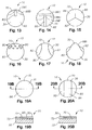
- thermal degradation relating to wear rates as shown in curve 'C' of Figure 10 can be engineered into PCD elements 2 where it is beneficial. For example, it may be desirable to have edges of curved cutting elements 10 remote from the center of contact to wear more quickly than the center point. This would tend to preserve the curved shape of the cutting element, rather than having it become a flat surface.
- Improved thermal degradation resistance improves wear rates because diamond is an extremely good thermal conductor. If a friction event at working surface 4, 70, 72 caused a sudden, extreme heat input, the bonded diamond crystals would conduct the heat in all directions away from the event. This would permit an extremely high temperature gradient through the material, possibly 1000 C per mm or higher. A gradient this steep would enable the working surface 4, 70, 72 to reach 950 C, and not cause significant thermal degradation if interstices 62 and the surfaces of the diamond crystals 62 adjacent to the working surface are substantially free of the catalyzing material 64 to a depth of just 0.2 mm from the source of the heat.
- the temperature gradient will vary depending upon the crystal 60 size and the amount of inter-crystal bonding.
- One convenient way to characterize this is the volume density of the diamond in the body 8. Under normal manufacturing methods, as the volume density of the diamond increases, the potential temperature gradient through the material also increases. This implies that a material otherwise identical that which produced curve 'B' in Figure 10, save for an increased diamond volume density, would subsequently produce a wear index closer to the curve 'A' in Figure 10.
- a distance D of less than 0.1 mm could provide approximately the same wear index in a cutting element with a diamond density of the body approaching 99% as the 0.2 mm to 0.3 mm D distance in a body with 85% to 90% diamond volume density.
- Another way to quantify this is to express the minimum amount of catalyzing material 64 remaining in the interstices 62 as a volume percent. It is known that with a very thin, flat diamond layer, a 0.15 mm layer containing the catalyzing material 64 is required in a 0.5 mm thick body. It is therefore reasonable to assume that a minimum of 30% of the volume of the body 8 must have interstices 62 containing the catalyzing material 64 for PDC elements of the present invention, particularly with the size ranges of typically used PDC cutters.
- PCD elements there are other possible constructions of PCD elements that benefit from depletion or removal of the catalyzing material 64 as described above.
- FIGs 11A, 11B and 11C another embodiment of the present invention is a compound PCD element 102.
- the PCD element 102 has a body 108 with a group VIII binder-catalyzing material with a second preformed PCD element 110 embedded within it.
- the embedded PCD element 110 may be flush with the working surface 104 of the encapsulating PCD element 120 as shown in Figure 11A, or it may be embedded wholly within the encapsulating PCD element 120 as shown in Figure 11B.
- This embedded PCD element 110 is made in a process using powdery carbonates of Mg, Ca, Sr, and Ba as the binder-catalyzing material, and is formed into a compound PCD element as described in the commonly assigned co-pending U.S. Patent No. 6,248,447 herein incorporated by reference.
- the embedded preformed PCD element 110 since the embedded preformed PCD element 110 is formed at higher pressures, the diamond density may be made higher than that of the encapsulating PCD element 120.
- the embedded PCD element 110 since the embedded PCD element 110 has a catalyzing material with a higher activation temperature, it may for example, be beneficial to deplete the catalyzing material only in the working surface of the encapsulating PCD element 120.
- the embedded PCD element 110 may be positioned within the encapsulating PCD element 120 to take advantage of the higher impact resistance of the embedded PCD element 110 combined with the improved wear resistance of the encapsulating element 120.
- the element 102 has a plurality of partially bonded diamond crystals 60, a catalyzing material 64 and a body 108 with a working surface 104.
- the volume 112 of the body adjacent the working surface 104 has a substantially higher diamond density than elsewhere 114 in the body 108, and the volume 112 is substantially free of the catalyzing material 64.
- embedded PCD elements 110 may be arranged in the compound element 100, as shown in Figure 11C, in a manner where the best of both impact resistance and improved wear resistance may be realized.
- PCD element 2 of the present invention is as cutting elements 10, 50, 52 as shown in Figures 1B, 4 and 5, and Figures 13-36B.
- the working surface of the PCD cutting elements 10, 50, 52 may be a top working surface 70 and/or a peripheral working surface 72.
- the PCD cutting element 10 of Figure 1B is one that may be typically used in fixed cutter type rotary drill bits 12, or for gauge protection in other types of downhole tools.
- the PCD cutting element 50 shown in Figure 5 may be shaped as a dome 39. This type of PCD cutting element 50 has an extended base 51 for insertion into sockets in a rolling cutter drill bit 38 or in the body of both types of rotary drill bits, 12, 38 as will be described in detail.
- the PCD cutting element 52 of Figure 4 is adapted for use in a machining process.
- the configuration of the cutting element 52 in Figure 4 is rectangular, it would be appreciated by those skilled in the art that this element could be triangular, quadrilateral or many other shapes suitable for machining highly abrasive products that are difficult to machine with conventional tools.
- the PCD cutting element 10 may be a preform cutting element 10 of a fixed cutter rotary drill bit 12 (as shown in Figure 2).
- the bit body 14 of the drill bit is formed with a plurality of blades 16 extending generally outwardly away from the central longitudinal axis of rotation 18 of the drill bit. Spaced apart side-by-side along the leading face 20 of each blade is a plurality of the PCD cutting elements 10 of the present invention.
- the PCD cutting element 10 has a body in the form of a circular tablet having a thin front facing table 30 of diamond or diamond-like (PCD) material, bonded in a high-pressure high-temperature press to a substrate 32 of less hard material such as cemented tungsten carbide or other metallic material.
- the cutting element 10 is preformed and then typically bonded on a generally cylindrical carrier 34 which is also formed from cemented tungsten carbide, or may alternatively be attached directly to the blade.
- the PCD cutting element 10 has working surfaces 70 and 72.
- the cylindrical carrier 34 is received within a correspondingly shaped socket or recess in the blade 16.
- the carrier 34 will usually be brazed or shrink fit in the socket.
- the fixed cutter drill bit 12 is rotated and weight is applied. This forces the cutting elements 10 into the earth being drilled, effecting a cutting and/or drilling action.
- the PCD cutting elements 10 may also be applied to the gauge region 36 of the bit 12 to provide a gauge reaming action as well as protecting the bit 12 from excessive wear in the gauge region 36. In order to space these cutting elements 10 as closely as possible, it may be desirable to cut the elements into shapes, such as the rectangular shape shown, which more readily fit into the gauge region 36.
- the cutting element 50 (as shown in Figure 5) of the present invention is on a rolling cutter type drill bit 38, shown in Figure 3.
- a rolling cutter drill bit 38 typically has one or more truncated rolling cone cutters 40, 41, 42 assembled on a bearing spindle on the leg 44 of the bit body 46.
- the cutting elements 50 may be mounted as one or more of a plurality of cutting inserts arranged in rows on rolling cutters 40, 41, 42, or alternatively the PCD cutting elements 50 may be arranged along the leg 44 of the bit 38.
- the PCD cutting element 50 has a body in the form of a facing table 35 of diamond or diamond like material bonded to a less hard substrate 37.
- the facing table 35 in this embodiment of the present invention is in the form of a domed surface 39 and has working surfaces 70 and 72. Accordingly, there are often a number of transitional layers between the facing table 35 and the substrate 37 to help more evenly distribute the stresses generated during fabrication, as is well known to those skilled in the art.
- the rolling cutter drill bit 38 In operation the rolling cutter drill bit 38 is rotated and weight is applied. This forces the cutting inserts 50 in the rows of the rolling cone cutters 40, 41, 42 into the earth, and as the bit 36 is rotated the rolling cutters 40, 41, 42 turn, effecting a drilling action.
- the PCD cutting element 52 of the present invention is in the form of a triangular, rectangular or other shaped material for use as a cutting insert in machining operations.
- the cutting element 52 has a body in the form of a facing table 54 of diamond or diamond like material bonded to a less hard substrate 56 with working surfaces 70 and 72.
- the cutting element 52 would then be cut into a plurality of smaller pieces which are subsequently attached to an insert 58 that is mounted in the tool holder of a machine tool.
- the cutting element 52 may be attached to the insert by brazing, adhesives, welding, or clamping. It is also possible to finish form the cutting element 52 in the shape of the insert in a high-temperature high-pressure manufacturing process.
- the PCD cutting elements 10 all have a portion 80 of the working surface 70, 72 which is treated as hereinbefore described to increase the wear resistance of the cutting elements 10.
- Each may also have another surface 82 which is not treated such that some catalyzing material 64 remains in the interstices 62.
- the another surface 84 may be only partially treated, or at least less treated than the surface 80.
- Shown in Figures 19A and 19B is a surface 86 that a gradual change in the treatment is indicated.
- Figures 13-17 are front views of PCD cutting elements 10 showing different arrangements of varied wear resistance on the working surfaces.
- the worn profile is indicated by numerals 88A, 88B, 88C.
- these worn profiles indicate the more wear resistant portions cause the element 10 to be self-sharpening.
- the element 10 wears in a relatively flat manner as indicated by 88C until enough wear has occurred to expose the more wear resistant portion. This allows an initial operation as a 'normal' element until the more wear resistant portion is exposed in 88D and 88E, where the element then becomes self-sharpening as can be seen.
- Figures 15-18 a front view showing the expected wear pattern of the PCD cutting element of Figure 17.
- Each has a treated surface 80 and a surface 82 which is not treated such that some catalyzing material 64 remains in the interstices 62.
- Figure 15 shows another surface 84 which is only partially treated, or at least less treated than the surface 80.
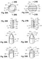
- Figures 19A and 19B show a surface 86 where a gradual change in the treatment is indicated, and Figures 20A and 20B show three zones similar to Figure 15. Other similar variations in the treatment are shown in Figures 21A to Figure 25 where the elements 10 have a relative sharp cutting tip rather than the rounded tips previously shown. Again, each has a treated surface 80, 84, 86 and a surface 82 which is not treated such that some catalyzing material 64 remains in the interstices 62, as previously described.
- Figures 26A - 27B show more views of PCD cutting elements 10 with different arrangements of varied wear resistance on the working surfaces.
- the worn profiles are indicated by numerals 88G, 88H.
- Figures show cutters wearing in a beneficial mode.
- Figures 26A and 26B show a chip breaking profile 90 forming as the element wears
- Figures 27A and 27B show cutting ridges 92 forming.
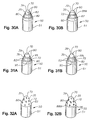
- Figure 28A - 32B show arrangements of varied wear resistance on the working surfaces of domed shaped PCD cutting elements 50 suitable for use in other cutting applications.
- Figures 28A, 29A, 30A, 31A, and 32A all show different arrangements with a treated surface 80 and a surface 82 which is not treated such that some catalyzing material 64 remains in the interstices 62.
- another surface 84 which is only partially treated, or at least less treated than the surface 80 may also be included.
- Figure 28B, 29B, 30B, 31B, and 32B all show cutters wearing in a beneficial mode.
- Figure 28B shows an inward taper wear mode revealed by wear profile 881.
- Figures 29B, 30B, 31B show various configurations of ridges, such as the crests 94 of Figure 29B revealed by wear profile 88J, the rings 96 of Figure 30B revealed by wear profile 88K, the spiral 95 of Figure 31B revealed by wear profile 88L, and the bumps 96 of Figure 32B revealed by wear profile 88M.
- Figures 33-36 are perspective views showing different arrangements of varied wear resistance on the front and side working surfaces of PCD cutting elements 10. Again, each has a treated surface 80 and a surface 82 which is not treated such that some catalyzing material 64 remains in the interstices 62, as previously described. These figures show elements 10 with two working surfaces 70, 72 that indicate the varied wear resistance may be applied to either or both surfaces. Although not shown, another surface 84, 86 (as previously described) which is only partially treated, or at least less treated than the surface 80 may also be included in place of portions of the untreated surface 82.
Abstract
Description
- The invention relates to superhard polycrystalline material elements for wear, cutting, drawing, and other applications where engineered superhard surfaces are needed. The invention particularly relates to polycrystalline diamond and polycrystalline diamond-like (collectively called PCD) elements with greatly improved wear resistance and methods of manufacturing them.
- Polycrystalline diamond and polycrystalline diamond-like elements are known, for the purposes of this specification, as PCD elements. PCD elements are formed from carbon based materials with exceptionally short inter-atomic distances between neighboring atoms. One type of diamond-like material similar to PCD is known as carbonitride (CN) described in U.S Patent No. 5,776,615. In general, PCD elements are formed from a mix of materials processed under high-temperature and high-pressure into a polycrystalline matrix of inter-bonded superhard carbon based crystals. A common trait of PCD elements is the use of catalyzing materials during their formation, the residue from which, often imposes a limit upon the maximum useful operating temperature of the element while in service.
- A well known, manufactured form of PCD element is a two-layer or multi-layer PCD element where a facing table of polycrystalline diamond is integrally bonded to a substrate of less hard material, such as tungsten carbide. The PCD element may be in the form of a circular or part-circular tablet, or may be formed into other shapes, suitable for applications such as hollow dies, heat sinks, friction bearings, valve surfaces, indentors, tool mandrels, etc. PCD elements of this type may be used in almost any application where a hard wear and erosion resistant material is required. The substrate of the PCD element may be brazed to a carrier, often also of cemented tungsten carbide. This is a common configuration for PCD's used as cutting elements, for example in fixed cutter or rolling cutter earth boring bits when received in a socket of the drill bit, or when fixed to a post in a machine tool for machining. These PCD elements are typically called polycrystalline diamond cutters (PDC).
- There are numerous variations in the methods of manufacture of these PDC elements. For example various ranges of average diamond particle sizes may be utilized in the manufacture to enhance wear properties as shown in U.S. Patents Nos, 4,861,350; 5,468,268; and 5,505,748 all herein incorporated by reference for all they disclose. Also, methods to provide a range of wear resistance across or into the working surface of a PDC are shown in U.S. Patent Nos. 5,135,061 and 5,607,024 also herein incorporated by reference for all they disclose. However, because the wear resistance is varied by changing the average size of the diamond particles, there is an inherent trade-off between impact strength and wear resistance in these designs. As a consequence, the PDC elements with the higher wear resistance will tend to have poor impact strength, which for PDC's used in drilling applications, is often unacceptable.
- Typically, higher diamond volume densities in the diamond table increases wear resistance at the expense of impact strength. However, modern PDC elements typically utilize often complex geometrical interfaces between the diamond table and the substrate as well as other physical design configurations to improve the impact strength. Although this allows wear resistance and impact strength to be simultaneously maximized, the tradeoff still exists, and has not significantly changed for the past several years prior to the present invention.
- Another form of PCD element is a unitary PCD element without an integral substrate where a table of polycrystalline diamond is fixed to a tool or wear surface by mechanical means or a bonding process. These PCD elements differ from those above in that diamond particles are present throughout the element. These PCD elements may be held in place mechanically, they may be embedded within a larger PCD element that has a substrate, or, alternately, they may be fabricated with a metallic layer which may be bonded with a brazing or welding process. A plurality of these PCD elements may be made from a single PCD, as shown, for example, in U.S. Patent Numbers 4,481,016 and 4,525,179 herein incorporated by reference for all they disclose.
- PCD elements are most often formed by sintering diamond powder with a suitable binder-catalyzing material in a high-pressure, high-temperature press. One particular method of forming this polycrystalline diamond is disclosed in U.S. Patent No. 3,141,746 herein incorporated by reference for all it discloses. In one common process for manufacturing PCD elements, diamond powder is applied to the surface of a preformed tungsten carbide substrate incorporating cobalt. The assembly is then subjected to very high temperature and pressure in a press. During this process, cobalt migrates from the substrate into the diamond layer and acts as a binder-catalyzing material, causing the diamond particles to bond to one another with diamond-to-diamond bonding, and also causing the diamond layer to bond to the substrate.
- The completed PCD element has at least one body with a matrix of diamond crystals bonded to each other with many interstices containing a binder-catalyzing material as described above. The diamond crystals comprise a first continuous matrix of diamond, and the interstices form a second continuous matrix of interstices containing the binder-catalyzing material. In addition, there are necessarily a relatively few areas where the diamond to diamond growth has encapsulated some of the binder-catalyzing material. These 'islands' are not part of the continuous interstitial matrix of binder-catalyzing material.
- In one common form, the diamond body constitutes 85% to 95% by volume and the binder-catalyzing material the other 5% to 15%. Such an element may be subject to thermal degradation due to differential thermal expansion between the interstitial cobalt binder-catalyzing material and diamond matrix beginning at temperatures of about 400 degrees C. Upon sufficient expansion the diamond-to-diamond bonding may be ruptured and cracks and chips may occur.
- Also in polycrystalline diamond, the presence of the binder-catalyzing material in the interstitial regions adhering to the diamond crystals of the diamond matrix leads to another form of thermal degradation. Due to the presence of the binder-catalyzing material, the diamond is caused to graphitize as temperature increases, typically limiting the operation temperature to about 750 degrees C.
- Although cobalt is most commonly used as the binder-catalyzing material, any group VIII element, including cobalt, nickel, iron, and alloys thereof, may be employed.
- To reduce thermal degradation, so-called "thermally stable" polycrystalline diamond components have been produced as preform PCD elements for cutting and/or wear resistant elements, as disclosed in U.S. Patent No. 4,224,380 herein incorporated by reference for all it discloses. In one type of thermally stable PCD element the cobalt or other binder-catalyzing material in conventional polycrystalline diamond is leached out from the continuous interstitial matrix after formation. Numerous methods for leaching the binder-catalyzing material are known. Some leaching methods are disclosed, for example, in U.S. Patent Nos. 4,572,722 and 4,797,241 both herein incorporated by reference for all they disclose.
- While leaching the binder-catalyzing material may increase the temperature resistance of the diamond to about 1200 degrees C, the leaching process also removes the cemented carbide substrate. In addition, because there is no integral substrate or other bondable surface, there are severe difficulties in mounting such material for use in operation.
- The fabrication methods for this 'thermally stable' PCD element typically produce relatively low diamond volume densities, typically of the order of 80 volume % or less. This low diamond volume density enables a thorough leaching process, but the resulting finished part is typically relatively weak in impact strength. The low volume density is typically achieved by using an admixtures process and using relatively small diamond crystals with average particle sizes of about 15 microns or less. These small particles are typically coated with a catalyzing material prior to processing. The admixtures process causes the diamond particles to be widely spaced in the finished product and relatively small percentages of their outer surface areas dedicated to diamond-to-diamond bonding, often less than 50%, contributing to the low impact strengths.
- In these so-called "thermally stable" polycrystalline diamond components, the lack of a suitable bondable substrate for later attachment to a work tool has been addressed by several methods. One such method to attach a bondable substrate to a "thermally stable" polycrystalline diamond preform is shown in U.S. Patent No. 4,944,772 herein incorporated by reference for all it discloses. In this process, a porous polycrystalline diamond preform is first manufactured, and then it is re-sintered in the presence of a catalyzing material at high-temperatures and pressures with a barrier layer of other material which, in theory, prevents the catalyzing material from re-infiltrating the porous polycrystalline diamond preform. The resulting product typically has an abrupt transition between the preform and the barrier layer, causing problematic stress concentrations in service. This product would be considered to be more a joined composite than an integral body.
- Other, similar processes to attach a bondable substrate to "thermally stable" polycrystalline diamond components are shown in U.S. Patent Nos. 4,871,377 and 5,127,923 herein incorporated by reference for all they disclose. It is believed that the weakness of all these processes is the degradation of the diamond-to-diamond bonds in the polycrystalline diamond preform from the high temperature and pressure re-sintering process. It is felt that this degradation generally further reduces the impact strength of the finished product to an unacceptably low level below that of the preform.
- In an alternative form of thermally stable polycrystalline diamond, silicon is used as the catalyzing material. The process for making polycrystalline diamond with a silicon catalyzing material is quite similar to that described above, except that at synthesis temperatures and pressures, most of the silicon is reacted to form silicon carbide, which is not an effective catalyzing material. The thermal resistance is somewhat improved, but thermal degradation still occurs due to some residual silicon remaining, generally uniformly distributed in the interstices of the interstitial matrix. Again, there are mounting problems with this type of PCD element because there is no bondable surface.
- More recently, a further type of PCD has become available in which carbonates, such as powdery carbonates of Mg, Ca, Sr, and Ba are used as the binder-catalyzing material when sintering the diamond powder. PCD of this type typically has greater wear-resistance and hardness than the previous types of PCD elements. However, the material is difficult to produce on a commercial scale since much higher pressures are required for sintering than is the case with conventional and thermally stable polycrystalline diamond. One result of this is that the bodies of polycrystalline diamond produced by this method are smaller than conventional polycrystalline diamond elements. Again, thermal degradation may still occur due to the residual binder-catalyzing material remaining in the interstices. Again, because there is no integral substrate or other bondable surface, there are difficulties in mounting this material to a working surface.
- Other efforts to combine thermally stable PCD's with mounting systems to put their improved temperature stability to use have not been as successful as hoped due to their low impact strength. For example, various ways of mounting multiple PCD elements are shown in U.S. Patent Nos. 4,726,718; 5,199,832; 5,205,684; 5,238,074; 6,009,963 herein incorporated by reference for all they disclose. Although many of these designs have had commercial success, the designs have not been particularly successful in combining high wear and/or abrasion resistance while maintaining the level of toughness attainable in non-thermally stable PCD.
- Other types of diamond or diamond like coatings for surfaces are disclosed in U.S. Patent Nos. 4,976,324; 5,213,248; 5,337,844; 5,379,853; 5,496,638; 5,523,121; 5,624,068 all herein incorporated by reference for all they disclose. Similar coatings are also disclosed in GB Patent Publication No. 2,268,768, PCT Publication No. 96/34,131, and EPC Publications 500,253; 787,820; 860,515 for highly loaded tool surfaces. In these publications, diamond and/or diamond like coatings are shown applied on surfaces for wear and/or erosion resistance.
- In many of the above applications physical vapor deposition (PVD) and/or chemical vapor deposition (CVD) processes are used to apply the diamond or diamond like coating. PVD and CVD diamond coating processes are well known and are described for example in U.S. Patent Nos. 5,439,492; 4,707,384; 4,645,977; 4,504,519; 4,486,286 all herein incorporated by reference.
- PVD and/or CVD processes to coat surfaces with diamond or diamond like coatings may be used, for example, to provide a closely packed set of epitaxially oriented crystals of diamond or other superhard crystals on a surface. Although these materials have very high diamond densities because they are so closely packed, there is no significant amount of diamond to diamond bonding between adjacent crystals, making them quite weak overall, and subject to fracture when high shear loads are applied. The result is that although these coatings have very high diamond densities, they tend to be mechanically weak, causing very poor impact toughness and abrasion resistance when used in highly loaded applications such as with cutting elements, bearing devices, wear elements, and dies.
- Some attempts have been made to improve the toughness and wear resistance of these diamond or diamond like coatings by application to a tungsten carbide substrate and subsequently processing in a high-pressure, high-temperature environment as described in U.S. Patent Nos. 5,264,283; 5,496,638; 5,624,068 herein incorporated by reference for all they disclose. Although this type of processing may improve the wear resistance of the diamond layer, the abrupt transition between the high-density diamond layer and the substrate make the diamond layer susceptible to wholesale fracture at the interface at very low strains, similar to the above described problems encountered with composite structures having barrier layers. This again translates to very poor toughness and impact resistance in service.
- When PCD elements made with a cobalt or other group VIII metal binder-catalyzing material were used against each other as bearing materials, it was found that the coefficient of friction tended to increase with use. As described in US Patent No. 5,560,716 herein incorporated by reference for all it discloses and corollary European Patent specification number 617,207, it was found that removal (by use of a hydrochloric acid wipe) of the cobalt-rich tribofilm which tended to build up in service from the surface of the PCD bearing element, tended to temporarily mitigate this problem. It was speculated that, during operation, some of the cobalt from the PCD at the surface migrates to the load area of the bearing, causing increased friction when two PCD elements act against each other as bearings. It is now believed that the source of this cobalt may be a residual by-product of the finishing process of the bearing elements, as the acid wipe remedy cannot effectively remove the cobalt to any significant depth below the surface.
- Because the cobalt is removed only from the surface of the PCD, there is no effective change in the temperatures at which thermal degradation occurs in these bearing elements. Therefore the deleterious effects of the binder-catalyzing material remain, and thermal degradation of the diamond layer due to the presence of the catalyzing material still occurs.
- The present invention provides a superhard polycrystalline diamond or diamond-like element with greatly improved wear resistance without loss of impact strength. Collectively called PCD elements for the purposes of this specification, these elements are formed with a binder-catalyzing material in a high-temperature, high-pressure (HTHP) process. The PCD element has a plurality of partially bonded diamond or diamond-like crystals forming a continuous diamond matrix body with a diamond volume density greater than 85%. Interstices among the diamond crystals form a continuous interstitial matrix containing a catalyzing material. The diamond matrix table is formed and integrally bonded to a substrate containing the catalyzing material during the HTHP process. The diamond matrix body has a working surface, where a portion of the interstitial matrix in the body adjacent to the working surface is substantially free of the catalyzing material, and the remaining interstitial matrix contains the catalyzing material. Typically, less than about 70% of the body of the diamond matrix table is free of the catalyzing material.
- The working surface that is substantially free of the catalyzing material is not subject to the thermal degradation encountered in the other areas of the working surface, resulting in improved wear resistance without loss of impact strength. In cutting elements, the processed working surface may be a portion of the facing table of the body, a portion of the peripheral surface of the body, or portions of all these surfaces.
- In another embodiment, the catalyzing material is cobalt or other iron group metal, and the method of depleting the catalyzing material is to leach it from the interstices near the surface of a PCD element in an acid etching process. It is anticipated that the method of removing the catalyzing material from the surface may also be by electrical discharge, or other electrical or galvanic process, or by evaporation.
- A further method of manufacture of a PCD element comprising a body integrally formed with a metallic substrate, the body comprising bonded diamond crystals and a catalyzing material is also disclosed. The treatment is performed by treating the body to render a volume thereof substantially free of the catalyzing material while permitting the catalyzing material to remain in at least some of the remaining volume of the body and while permitting the substrate to remain substantially unaffected when treating the body. The treatment provides an enhanced wear resistance to the treated portion of the element while maintaining the impact strength of the entire element substantially the same.
- Disclosed is an element having a body comprising a plurality of partially bonded diamond crystals, a catalyzing material and an interstitial matrix; the body having a working surface. The interstitial matrix in the body adjacent to the working surface is substantially free of the catalyzing material, and the remaining interstitial matrix contains the catalyzing material. The portion of the working surface that is substantially free of the catalyzing material has substantially the same impact strength as the remaining interstitial matrix.
- Similarly, a PCD element is disclosed with a body having a catalyzing material, an interstitial matrix, and a working surface. The interstitial matrix in the body adjacent to the working surface is substantially free of the catalyzing material, and the remaining interstitial matrix contains the catalyzing material.
- Furthermore, a PCD element is disclosed having a body with a working surface. A first volume of the body remote from the working surface contains a catalyzing material, and a second volume of the body adjacent to the working surface is substantially free of the catalyzing material.
- A PCD element is also disclosed comprising a diamond containing body integrally formed with a metallic substrate. The body has at least an 85% by volume diamond density and an interstitial matrix. The interstitial matrix in the body adjacent to a working surface is substantially free of the catalyzing material, and the interstitial regions where the body contacts the substrate contain the catalyzing material and have an average thickness greater than 0.15mm.
- Furthermore, a PCD element comprising a body of bonded diamonds integrally formed with a metallic substrate. The body has a working surface and at least an 85% by volume diamond density. A first volume of the body adjacent to the working surface contains a catalyzing material, and a second volume of the body adjacent to the working surface is substantially free of the catalyzing material. The first volume and the second volume have substantially the same impact strength.
- A PCD element comprising a diamond containing body integrally formed with a metallic substrate. The body having at least an 85% by volume diamond density and an interstitial matrix, a first portion of the interstitial matrix in the body adjacent to a working surface is substantially free of the catalyzing material, a second portion of the interstitial matrix in the body adjacent to a working surface contains the catalyzing material. The interstitial matrix where the body contacts the substrate contains the catalyzing material and has an average thickness greater than 0.15 mm. The first portion of the interstitial matrix and the second portion of the interstitial matrix have substantially the same impact strength.
- In addition, a preform cutting element is disclosed. It has a body of a superhard polycrystalline material comprising a plurality of partially bonded superhard crystals integrally formed with a metallic substrate, a plurality of interstitial regions among the superhard crystals and a catalyzing material. The body has at least an 85% by volume diamond density and a cutting surface. The interstitial regions adjacent to at least a first portion of the cutting surface are substantially free of the catalyzing material, the interstitial regions adjacent to a second portion of the cutting surface contain the catalyzing material, and the interstitial regions where the body contacts the substrate contain the catalyzing material and have an average thickness greater than 0.15 mm. Also, the first portion of the cutting surface and the second portion have substantially the same impact strength.
- The PCD elements of the present invention may be used for wear, cutting, drawing, and other applications where engineered diamond surfaces are needed. Specific applications are as cutting elements in rotary drill bits of both the fixed cutter type and the rolling cutter type, as hollow dies, heat sinks, friction bearings, valve surfaces, indentors, tool mandrels, etc. The PCD element of the present invention may be used to machine abrasive wood products, ferrous and nonferrous materials and also very hard or abrasive engineering materials such as stone and asphalt and the like.
- The invention will further be described, by way of example, with reference to the accompanying drawings, in which:
- Figure 1A is a typical PCD element of the present invention.
- Figure 1B is a typical PCD of the present invention shown as a cutting element.
- Figure 2 is a side view of a fixed cutter rotary drill bit using a PCD element of the present invention.
- Figure 3 is a perspective view of a rolling cutter rotary drill bit using a PCD element of the present invention.
- Figure 4 is a perspective view of an insert used in machine tools utilizing the PCD element of the present invention.
- Figure 5 is a perspective view of a dome shaped PCD element suitable for use in both rolling cutter drill bits and in fixed cutter drill bits.
- Figure 6 is a photo-micrograph of the surface of a PCD element of the prior art showing the binder-catalyzing material in the interstitial regions.
- Figure 7 is a photo-micrograph of the PCD element of the present invention showing a first portion with a catalyzing material in the interstitial regions and a second portion without the catalyzing material in the interstitial regions.
- Figure 8 is a micro-structural representation of a PCD element of the prior art, showing the bonded diamond crystals, with the interstitial regions and the random crystallographic orientation of the individual crystals.
- Figure 9 is a micro-structural representation of the PCD element of the present invention as shown in Figure 7, indicating the depth of the catalyzing material free region relative to the surface of the PCD element.
- Figure 10 is a graph of the relative wear indices of several embodiments of the PCD element of the present invention.
- Figure 11A is a front view of an encapsulated PCD embodiment of the PCD element of the present invention.
- Figure 11B is a section view of another encapsulated PCD embodiment of the PCD element of the present invention.
- Figure 11C is a section view of still another encapsulated PCD embodiment of the PCD element of the present invention.
- Figure 12 is a graph representing the typical abrasive wear resistance vs. impact resistance of the prior art cutting elements compared with a cutting element of the present invention.
- Figures 13-17 are front views showing different arrangements of varied wear resistance on the working surfaces of PCD cutting elements of the present invention.
- Figure 18 is a front view showing the expected wear pattern of the PCD cutting element of Figure 17.
- Figure 19A is a front view showing an arrangement of a continuously varying wear resistance on the working surface of a PCD cutting element of the present invention.
- Figure 19B is a section view of the PCD cutting elements of Figure 19A showing the treatment gradient.
- Figure 20A is a front view showing another arrangement of varied wear resistance on the working surfaces of PCD cutting elements of the present invention.
- Figure 20B is a section view of the PCD cutting elements of Figure 20A showing the treatment gradient.
- Figure 21A is a front view showing another arrangement of varied wear resistance on the working surfaces of PCD cutting elements of the present invention.
- Figure 21B is a section view of the PCD cutting element of Figure 21A showing the treatment gradient.
- Figure 22A is a front view showing another arrangement of varied wear resistance on the working surfaces of PCD cutting elements of the present invention.
- Figure 22B is a section view of the PCD cutting element of Figure 22A showing the treatment gradient.
- Figure 23A is a front view showing another arrangement of varied wear resistance on the working surfaces of PCD cutting elements of the present invention.
- Figure 23B is a section view of the PCD cutting element of Figure 23A showing the treatment gradient.
- Figures 24A, 24B and 25 are front views showing different arrangements of varied wear resistance on the working surfaces of PCD cutting elements of the present invention.
- Figure 26A is a front view showing another arrangement of varied wear resistance on the working surfaces of PCD cutting elements of the present invention.
- Figure 26B is a section view showing how the PCD cutting element of Figure 26A may wear in use.
- Figure 27A is a front view showing another arrangement of varied wear resistance on the working surfaces of PCD cutting elements of the present invention.
- Figure 27B is a section view showing how the PCD cutting element of Figure 27A may wear in use.
- Figure 28A is a front view showing an arrangement of varied wear resistance on the working surfaces of domed shaped PCD cutting elements of the present invention.
- Figure 28B is a section view showing how the PCD cutting element of Figure 28A may wear in use.
- Figure 29A is a front view showing an arrangement of varied wear resistance on the working surfaces of domed shaped PCD cutting elements of the present invention.
- Figure 29B is a section view showing how the PCD cutting element of Figure 29A may wear in use.
- Figure 30A is a front view showing an arrangement of varied wear resistance on the working surfaces of domed shaped PCD cutting elements of the present invention.
- Figure 30B is a section view showing how the PCD cutting element of Figure 30A may wear in use.
- Figure 31A is a front view showing an arrangement of varied wear resistance on the working surfaces of domed shaped PCD cutting elements of the present invention.
- Figure 31B is a section view showing how the PCD cutting element of Figure 31A may wear in use.
- Figure 32A is a front view showing an arrangement of varied wear resistance on the working surfaces of domed shaped PCD cutting elements of the present invention.
- Figure 32B is a section view showing how the PCD cutting element of Figure 32A may wear in use.
- Figures 33-36 are perspective views showing different arrangements of varied wear resistance on the front and side working surfaces of PCD cutting elements of the present invention.
-
- The polycrystalline diamond or diamond-like material (PCD)
element 2 of the present invention is shown in Figure 1A. ThePCD element 2 has a plurality of partially bonded superhard, diamond or diamond-like,crystals 60, (shown in Figures 7 and 9) a catalyzingmaterial 64, and an interstitial matrix 68 formed by theinterstices 62 among thecrystals 60. Theelement 2 also has one or more working surfaces 4 and thediamond crystals 60 and theinterstices 62 form the volume of thebody 8 of thePCD element 2. Preferably, theelement 2 is integrally formed with ametallic substrate 6, typically tungsten carbide with a cobalt binder material. To be effective when used in an abrasive wear application, the volume density of the diamond in thebody 8 must be greater than 85 volume %, and preferably be higher than 90%. - The working surface 4 is any portion of the
PCD body 8 which, in operation, may contact the object to be worked. In this specification, when the working surface 4 is discussed, it is understood that it applies to any portion of thebody 8 which may be exposed and/or used as a working surface. Furthermore, any portion of any of the working surface 4 is, in and of itself, a working surface. - During manufacture, under conditions of high-temperature and high-pressure (HTHP), the
interstices 62 among thecrystals 60 fill with the catalyzingmaterial 64 followed by bonds forming among thecrystals 60. In a further step of the manufacture, some of the catalyzingmaterial 64 is selectively depleted from some of the interstices 62. The result is that a first volume of thebody 8 of thePCD element 2 remote from the working surface 4 contains the catalyzingmaterial 64, and a second volume of thebody 8 adjacent to the working surface 4 is substantially free of the catalyzingmaterial 64. Theinterstices 62 which are substantially free of the catalyzingmaterial 64 are indicated bynumeral 66. - Therefore, the interstitial matrix 68 of the
body 8 adjacent to at least a portion of the working surface 4 is substantially free of the catalyzingmaterial 64, and the remaining interstitial matrix 68 contains the catalyzingmaterial 64. As previously stated, thePCD element 2 is preferably bonded in the HPHT process to asubstrate 6 of less hard material, usually cemented tungsten carbide or other metallic material, but use of asubstrate 6 is not required. - Because the body adjacent to the working surface 4 is substantially free of the catalyzing
material 64, the deleterious effects of the binder-catalyzingmaterial 64 are substantially decreased, and thermal degradation of the working surface 4 due to the presence of the catalyzingmaterial 64 is effectively eliminated. The result is anew PCD element 2 that has the enhanced thermal properties approximating that of the so called thermally stable PCD elements, while maintaining the toughness, convenience of manufacture, and bonding ability of the traditional PDC elements. This translates to higher wear resistance in cutting applications, higher heat transfer capacity in heat sink applications, higher load capacity in bearing applications, less surface distortion in valve applications, and has advantages in numerous other applications including hollow dies, indentors, tool mandrels, and wear elements. These benefits are gained without loss of impact strength in the elements. Details of specific applications of thenew PCD element 2 will be discussed in more detail later in the specification. - Referring now to the photo-micrograph of a prior art PCD element in Figure 6, and also the microstructural representation of a PCD element of the prior art in Figure 8, it is well known that there is a random crystallographic orientation of the diamond or diamond-
like crystals 60 as shown by the parallel lines representing the cleavage planes of eachcrystal 60. As can be seen,adjacent crystals 60 have bonded together withinterstitial spaces 62 among them. Because the cleavage planes are oriented in different directions onadjacent crystals 60 there is generally no straight path available for diamond fracture. This structure allows PCD materials to perform well in extreme loading environments where high impact loads are common. - In the process of bonding the
crystals 60 in a high-temperature, high-pressure press, theinterstitial spaces 62 among thecrystals 60 become filled with a binder-catalyzingmaterial 64. It is this catalyzingmaterial 64 that allows the bonds to be formed betweenadjacent diamond crystals 60 at the relatively low pressures and temperatures present in the press. - The prior art PCD element has at least one continuous matrix of
crystals 60 bonded to each other with themany interstices 62 containing a binder-catalyzingmaterial 64, typically cobalt or other group VIII element. Thecrystals 60 comprise a first continuous matrix of diamond, and theinterstices 62 form a second continuous matrix known as the interstitial matrix 68, containing the binder-catalyzing material. In addition, there are necessarily a relatively few areas where the diamond to diamond growth has encapsulated some of the binder-catalyzing material. These 'islands' are not part of the continuous interstitial matrix 68 of binder-catalyzingmaterial 64. - Referring now to Figures 7 and 9, shown is a cross section of the
PCD element 2 of the present invention. ThePCD element 2 may be formed in the same manner as the prior art PCD elements described above. In a preferred embodiment, after a preliminary cleanup operation or at any time thereafter in the process of manufacturing, the workingsurface PCD element 2 is processed in a manner which removes a portion of the binder-catalyzing material from the adjacent body. The result is that theinterstices 62 among thediamond crystals 60 adjacent to the working surface are substantially free of the catalyzingmaterial 64 indicated bynumeral 66. The portion of the workingsurface material 64 is not subject to the thermal degradation encountered in the other areas of the PCD, resulting in improved thermal characteristics. - The average diamond volume density in the
body 8 of thePCD element 2 of the present invention ranges from about 85% to about 99%. The high diamond volume density is achieved by usingdiamond crystals 60 with a range of particle sizes, with an average particle size ranging from about 30 to about 60 microns. Typically, the diamond mixture may comprise 20% to 60% diamond crystals 60 in the 5-15 micron range, 20% to 40% diamond crystals 60 in the 25-40 micron range, and 20% to 40% diamond crystals 60 in the 50-80 micron diameter range, although numerous other size ranges and percentages may be used. This mixture of large andsmall diamond crystals 60 allows thediamond crystals 60 to have relatively high percentages of their outer surface areas dedicated to diamond-to-diamond bonding, often approaching 95%, contributing to a relatively high apparent abrasion resistance. - There are many methods for removing or depleting the catalyzing
material 64 from the interstices 62. In one method, the catalyzingmaterial 64 is cobalt or other iron group material, and the method of removing the catalyzingmaterial 64 is to leach it from theinterstices 62 near the workingsurface PCD element 2 in an acid etching process to a depth of greater than about 0.2 mm. It is also possible that the method of removing the catalyzingmaterial 64 from near the surface may be by electrical discharge, or other electrical or galvanic process or by evaporation. - In another method for depleting the catalyzing
material 64 from theinterstices 62, the catalyzingmaterial 64 is depleted by combining it chemically, such as alloying, with another material such that it no longer acts as a catalyzing material. In this method, a material may remain in the interstices among thediamond crystals 60, but that material no longer acts as a catalyzing material 64 - effectively removing it. - In still another method for depleting the catalyzing
material 64 from theinterstices 62, the catalyzingmaterial 64 is removed by causing it to transform into a material that no longer acts as a catalyzing material. This may be accomplished by a crystal structure change, phase change, mechanical 'working', thermal treatment or other treatment methods. This method may apply to non-metallic or non-reactive catalyzing materials. Again, a material may remain in theinterstices 62 among the diamond crystals, but that material no longer acts as a catalyzing material 64 - effectively removing the catalyzing material. - Once the catalyzing
material 64 adjacent to the workingsurface PCD element 2 of the present invention is no longer susceptible to the type of thermal degradation known to occur in the prior art PCD elements. As previously described, there are two modes of thermal degradation known to be caused by the catalyzingmaterial 64. The first mode of thermal degradation begins at temperatures as low as about 400 degrees C and is due to differential thermal expansion between the catalyzingmaterial 64 in theinterstices 62 and thecrystals 60. Upon sufficient expansion the diamond-to-diamond bonding may be ruptured and cracks and chips may occur. - The second mode of thermal degradation begins at temperatures of about 750 degrees C. This mode is caused by the catalyzing ability of the binder-catalyzing
material 64 contacting thecrystals 60, and causing thecrystals 60 to graphitize as the temperature exceeds about 750 degrees C. As thecrystals 60 graphitize, they undergo a huge volume increase resulting in cracking and dis-bond from the body 4. Even a coating of a few microns of the catalyzingmaterial 64 on the surfaces of thediamond crystals 60 can enable this mode of thermal degradation. - It would therefore be appreciated by those skilled in the art that for maximum benefit, the catalyzing
material 64 must be removed both from theinterstices 62 among thediamond crystals 60 and from the surfaces of thediamond crystals 60 as well. If the catalyzingmaterial 64 is removed from both the surfaces of thediamond crystals 60 and from theinterstices 62 the onset of thermal degradation for thediamond crystals 60 in that region would approach 1200 C. - This dual degradation mode, however, provides some unexpected benefits. For example, in many applications it is desirable to engineer the wear rate of the working surface. In the present invention, this may be accomplished by changing the treatment process such that in areas requiring maximum wear resistance, the catalyzing material is depleted from both the
interstices 62 and the surfaces of thediamond crystals 60. In areas where less wear resistance is desired, for example in a self sharpening tool, those areas would be treated so as to deplete the catalyzingmaterial 64 primarily from theinterstices 62, but allowing some, if not all, of thediamond crystals 60 to remain in contact with the catalyzing material. - This selective treatment process could provide, for example, a cutting element that would be self-sharpening as is wears in operation. In these applications, the
PCD element body 8 of bondeddiamonds 60 integrally formed with ametallic substrate body 8 has a workingsurface body 8 adjacent to the workingsurface body 8 adjacent to the workingsurface - It should be apparent, that it is more difficult to remove the catalyzing
material 64 from the surfaces of thediamond crystals 60 than from the interstices 62. For this reason, depending upon the manner in which the catalyzing material is depleted, to be effective in reducing thermal degradation, the depth of depletion of the catalyzingmaterial 64 from the working surface 4 may vary depending upon the method used for depleting the catalyzingmaterial 64. - In some applications, improvement of the thermal threshold to above 400 C but less than 750 C is adequate, and therefore a less
intense catalyzing material 64 depletion process is permissible. As a consequence, it would be appreciated that there are numerous combinations of catalyzingmaterial 64 depletion methods which could be applied to achieve the level of catalyzingmaterial 64 depletion required for a specific application. - In this specification, when the term 'substantially free' is used referring to catalyzing
material 64 in theinterstices 62, the interstitial matrix 68, or in a volume of thebody 8, it should be understood that many, if not all, the surfaces of theadjacent diamond crystals 60 may still have a coating of the catalyzingmaterial 64. Likewise, when the term 'substantially free' is used referring to catalyzingmaterial 64 on the surfaces of thediamond crystals 60, there may still be catalyzingmaterial 64 present in theadjacent interstices 62. - With the catalyzing
material 64 removed or depleted, two major mechanisms for thermal degradation are no longer present. However, it has been found that the catalyzingmaterial 64 has to be removed at a depth sufficient to allow the bondedcrystals 60 to conduct away the heat generated by a thermal event to below the degradation temperature of thecrystals 60 where the catalyzingmaterial 64 is present. - In one set of laboratory tests, heat was input into a
PCD element 2 configured as a cuttingelement 10. Since this test was designed as a standard wear test for these cutting elements, it provided a reasonable comparison of cuttingelements 10 with various depths of the catalyzingmaterial 64 removal. In these tests, care was taken to assure the depletion process removed the catalyzingmaterial 64 from both theinterstices 62 and from the surfaces of thediamond crystals 60. The test was designed such that a repeatable input of heat was applied to the cutting edge of thePCD cutting element 10 for a known period of time. - Once the test was complete, a wear index was calculated. The higher the wear index, the better the wear resistance. Due to the nature of the test, it is assumed that an increased wear index number indicates increased resistance to thermal degradation of the working
surface element 10. - As can be seen in curve 'A' in the graph of Figure 10 there is a dramatic increase in the wear index result for cutting
elements 10 when the catalyzingmaterial 64 depletion depth approaches 0.1 mm. Therefore, for the types of heat input common in cuttingelements 10, a 0.1 mm depth is the critical depletion depth from the workingsurface material 64 is removed from bothinterstices 62 and from the surfaces of thediamond crystals 60. - In other tests, on cutting
elements 10 made with a more economical process for removing the catalyzingmaterial 64, the wear versus depth of depletion is believed to approximate that shown in curve 'B' of Figure 10. The catalyzingmaterial 64 depletion process used in these cutters was not as effective for removing the catalyzingmaterial 64 from the surfaces of thediamond crystals 60 as the process of curve 'A'. Therefore, it was not until most of the catalyzingmaterial 64 was removed from theinterstices 62 to a depth of about 0.2 mm that the wear rate improved to that of curve 'A'. It was found that the impact strength of these cuttingelements 10 was substantially unchanged from untreated elements. - Referring now to Figure 12, to visually demonstrate the comparison of the invention's improvement in wear resistance while maintaining impact strength, a typical, impact resistance versus abrasive wear resistance curve well known and well established for prior art cutting elements is indicated by curve 'W'. The point P on the graph relatively indicates the properties of the cutting element of the present invention. As can be seen, P lies in the top right corner area of the graph, which represents to those skilled in the art a significant and substantial improvement in wear resistance of cutting elements while maintaining impact strength.
- It is believed that thermal degradation relating to wear rates as shown in curve 'C' of Figure 10 can be engineered into
PCD elements 2 where it is beneficial. For example, it may be desirable to have edges ofcurved cutting elements 10 remote from the center of contact to wear more quickly than the center point. This would tend to preserve the curved shape of the cutting element, rather than having it become a flat surface. - Improved thermal degradation resistance improves wear rates because diamond is an extremely good thermal conductor. If a friction event at working
surface surface interstices 62 and the surfaces of thediamond crystals 62 adjacent to the working surface are substantially free of the catalyzingmaterial 64 to a depth of just 0.2 mm from the source of the heat. - It should be apparent that the temperature gradient will vary depending upon the
crystal 60 size and the amount of inter-crystal bonding. One convenient way to characterize this is the volume density of the diamond in thebody 8. Under normal manufacturing methods, as the volume density of the diamond increases, the potential temperature gradient through the material also increases. This implies that a material otherwise identical that which produced curve 'B' in Figure 10, save for an increased diamond volume density, would subsequently produce a wear index closer to the curve 'A' in Figure 10. - In field tests of cutting
elements 10 for earth boring bits, removal of substantially all of the catalyzingmaterial 64 from theinterstices 62 to a distance D of about 0.2 mm to about 0.3 mm from a workingsurface diamond crystals 60 due to catalyzingmaterial 64 induced thermal degradation was dramatically reduced. The rate of penetration increase is believed to be due to the ability of the cutter to remain 'sharper' longer due to the increased wear resistance. - It is believed, however, that as the volume density of the diamond in the
body 8 increases from the 85%-90% range to the 95%-99% range, the distance D needed to produce a particular wear index will decrease. Therefore, it is also believed that a distance D of less than 0.1 mm could provide approximately the same wear index in a cutting element with a diamond density of the body approaching 99% as the 0.2 mm to 0.3 mm D distance in a body with 85% to 90% diamond volume density. - It is important when removing the catalyzing
material 64 from theinterstices 62 that theunderlying substrate material 64 remaining in the interstices 62. It has been found that when depleting the catalyzingmaterial 64 from a flat surface having a planar interface with thesubstrate material 64 must remain to assure that theunderlying substrate - Quantifying this amount for PDC's in general is problematic, because some interaction of the depletion process and the substrate can be tolerated, and geometries can be complex. However, one way to quantify this is that the portion of the
body 8 contacting thesubstrate material 64 remaining in theinterstices 62 to an average thickness of greater than 0.15 mm. - Another way to quantify this is to express the minimum amount of catalyzing
material 64 remaining in theinterstices 62 as a volume percent. It is known that with a very thin, flat diamond layer, a 0.15 mm layer containing the catalyzingmaterial 64 is required in a 0.5 mm thick body. It is therefore reasonable to assume that a minimum of 30% of the volume of thebody 8 must haveinterstices 62 containing the catalyzingmaterial 64 for PDC elements of the present invention, particularly with the size ranges of typically used PDC cutters. - There are other possible constructions of PCD elements that benefit from depletion or removal of the catalyzing
material 64 as described above. As shown in Figures 11A, 11B and 11C another embodiment of the present invention is acompound PCD element 102. ThePCD element 102 has abody 108 with a group VIII binder-catalyzing material with a secondpreformed PCD element 110 embedded within it. The embeddedPCD element 110 may be flush with the workingsurface 104 of the encapsulatingPCD element 120 as shown in Figure 11A, or it may be embedded wholly within the encapsulatingPCD element 120 as shown in Figure 11B. This embeddedPCD element 110 is made in a process using powdery carbonates of Mg, Ca, Sr, and Ba as the binder-catalyzing material, and is formed into a compound PCD element as described in the commonly assigned co-pending U.S. Patent No. 6,248,447 herein incorporated by reference. - In this embodiment, since the embedded preformed
PCD element 110 is formed at higher pressures, the diamond density may be made higher than that of the encapsulatingPCD element 120. In this construction since the embeddedPCD element 110 has a catalyzing material with a higher activation temperature, it may for example, be beneficial to deplete the catalyzing material only in the working surface of the encapsulatingPCD element 120. Furthermore, the embeddedPCD element 110 may be positioned within the encapsulatingPCD element 120 to take advantage of the higher impact resistance of the embeddedPCD element 110 combined with the improved wear resistance of the encapsulatingelement 120. - As shown in Figures 9, 11A, 11B, and 11C, the
element 102 has a plurality of partially bondeddiamond crystals 60, a catalyzingmaterial 64 and abody 108 with a workingsurface 104. Thevolume 112 of the body adjacent the workingsurface 104 has a substantially higher diamond density than elsewhere 114 in thebody 108, and thevolume 112 is substantially free of the catalyzingmaterial 64. - Several embedded
PCD elements 110 may be arranged in the compound element 100, as shown in Figure 11C, in a manner where the best of both impact resistance and improved wear resistance may be realized. - It may be desirable to deplete the catalyzing material in the embedded
PCD element 110 as well as the catalyzing material of the encapsulatingPDC element 120. This combination would provide an element with the highest possible impact strength combined with the highest possible wear resistance available in diamond elements for commercial use. - One particularly useful application for the
PCD element 2 of the present invention is as cuttingelements PCD cutting elements surface 70 and/or a peripheral workingsurface 72. ThePCD cutting element 10 of Figure 1B is one that may be typically used in fixed cutter typerotary drill bits 12, or for gauge protection in other types of downhole tools. ThePCD cutting element 50 shown in Figure 5 may be shaped as adome 39. This type ofPCD cutting element 50 has an extendedbase 51 for insertion into sockets in a rollingcutter drill bit 38 or in the body of both types of rotary drill bits, 12, 38 as will be described in detail. - The
PCD cutting element 52 of Figure 4 is adapted for use in a machining process. Although the configuration of the cuttingelement 52 in Figure 4 is rectangular, it would be appreciated by those skilled in the art that this element could be triangular, quadrilateral or many other shapes suitable for machining highly abrasive products that are difficult to machine with conventional tools. - The
PCD cutting element 10 may be apreform cutting element 10 of a fixed cutter rotary drill bit 12 (as shown in Figure 2). Thebit body 14 of the drill bit is formed with a plurality ofblades 16 extending generally outwardly away from the central longitudinal axis ofrotation 18 of the drill bit. Spaced apart side-by-side along the leadingface 20 of each blade is a plurality of thePCD cutting elements 10 of the present invention. - Typically, the
PCD cutting element 10 has a body in the form of a circular tablet having a thin front facing table 30 of diamond or diamond-like (PCD) material, bonded in a high-pressure high-temperature press to asubstrate 32 of less hard material such as cemented tungsten carbide or other metallic material. The cuttingelement 10 is preformed and then typically bonded on a generallycylindrical carrier 34 which is also formed from cemented tungsten carbide, or may alternatively be attached directly to the blade. ThePCD cutting element 10 has workingsurfaces - The
cylindrical carrier 34 is received within a correspondingly shaped socket or recess in theblade 16. Thecarrier 34 will usually be brazed or shrink fit in the socket. In operation the fixedcutter drill bit 12 is rotated and weight is applied. This forces the cuttingelements 10 into the earth being drilled, effecting a cutting and/or drilling action. - The
PCD cutting elements 10 may also be applied to thegauge region 36 of thebit 12 to provide a gauge reaming action as well as protecting thebit 12 from excessive wear in thegauge region 36. In order to space these cuttingelements 10 as closely as possible, it may be desirable to cut the elements into shapes, such as the rectangular shape shown, which more readily fit into thegauge region 36. - In a second embodiment, the cutting element 50 (as shown in Figure 5) of the present invention is on a rolling cutter
type drill bit 38, shown in Figure 3. A rollingcutter drill bit 38 typically has one or more truncatedrolling cone cutters leg 44 of thebit body 46. The cuttingelements 50 may be mounted as one or more of a plurality of cutting inserts arranged in rows on rollingcutters PCD cutting elements 50 may be arranged along theleg 44 of thebit 38. ThePCD cutting element 50 has a body in the form of a facing table 35 of diamond or diamond like material bonded to a lesshard substrate 37. The facing table 35 in this embodiment of the present invention is in the form of adomed surface 39 and has workingsurfaces substrate 37 to help more evenly distribute the stresses generated during fabrication, as is well known to those skilled in the art. - In operation the rolling
cutter drill bit 38 is rotated and weight is applied. This forces the cutting inserts 50 in the rows of the rollingcone cutters bit 36 is rotated the rollingcutters - In another embodiment, the
PCD cutting element 52 of the present invention is in the form of a triangular, rectangular or other shaped material for use as a cutting insert in machining operations. In this embodiment, the cuttingelement 52 has a body in the form of a facing table 54 of diamond or diamond like material bonded to a lesshard substrate 56 with workingsurfaces element 52 would then be cut into a plurality of smaller pieces which are subsequently attached to aninsert 58 that is mounted in the tool holder of a machine tool. The cuttingelement 52 may be attached to the insert by brazing, adhesives, welding, or clamping. It is also possible to finish form the cuttingelement 52 in the shape of the insert in a high-temperature high-pressure manufacturing process. - As previously mentioned, it is desirable to selectively treat the faces of these
elements - In figures 13-27B and 33-36, the
PCD cutting elements 10 all have aportion 80 of the workingsurface elements 10. Each may also have anothersurface 82 which is not treated such that some catalyzingmaterial 64 remains in the interstices 62. Alternatively, the anothersurface 84 may be only partially treated, or at least less treated than thesurface 80. Shown in Figures 19A and 19B is asurface 86 that a gradual change in the treatment is indicated. - Describing the Figures in more detail, Figures 13-17 are front views of
PCD cutting elements 10 showing different arrangements of varied wear resistance on the working surfaces. In Figures 13 and 14 the worn profile is indicated bynumerals element 10 to be self-sharpening. In Figure 14, theelement 10 wears in a relatively flat manner as indicated by 88C until enough wear has occurred to expose the more wear resistant portion. This allows an initial operation as a 'normal' element until the more wear resistant portion is exposed in 88D and 88E, where the element then becomes self-sharpening as can be seen. - Other possible arrangements are shown in Figures 15-18, a front view showing the expected wear pattern of the PCD cutting element of Figure 17. Each has a treated
surface 80 and asurface 82 which is not treated such that some catalyzingmaterial 64 remains in the interstices 62. Figure 15 shows anothersurface 84 which is only partially treated, or at least less treated than thesurface 80. - Figures 19A and 19B show a
surface 86 where a gradual change in the treatment is indicated, and Figures 20A and 20B show three zones similar to Figure 15. Other similar variations in the treatment are shown in Figures 21A to Figure 25 where theelements 10 have a relative sharp cutting tip rather than the rounded tips previously shown. Again, each has a treatedsurface surface 82 which is not treated such that some catalyzingmaterial 64 remains in theinterstices 62, as previously described. - Figures 26A - 27B show more views of
PCD cutting elements 10 with different arrangements of varied wear resistance on the working surfaces. In Figures 26B and 27B the worn profiles are indicated bynumerals chip breaking profile 90 forming as the element wears, and Figures 27A and 27Bshow cutting ridges 92 forming. - Figure 28A - 32B show arrangements of varied wear resistance on the working surfaces of domed shaped
PCD cutting elements 50 suitable for use in other cutting applications. In a manner similar to what has been previously described, Figures 28A, 29A, 30A, 31A, and 32A all show different arrangements with a treatedsurface 80 and asurface 82 which is not treated such that some catalyzingmaterial 64 remains in the interstices 62. Although not shown, anothersurface 84 which is only partially treated, or at least less treated than thesurface 80 may also be included. - Corresponding Figures 28B, 29B, 30B, 31B, and 32B all show cutters wearing in a beneficial mode. Figure 28B shows an inward taper wear mode revealed by
wear profile 881. Figures 29B, 30B, 31B show various configurations of ridges, such as thecrests 94 of Figure 29B revealed bywear profile 88J, the rings 96 of Figure 30B revealed bywear profile 88K, thespiral 95 of Figure 31B revealed bywear profile 88L, and the bumps 96 of Figure 32B revealed bywear profile 88M. - Figures 33-36 are perspective views showing different arrangements of varied wear resistance on the front and side working surfaces of
PCD cutting elements 10. Again, each has a treatedsurface 80 and asurface 82 which is not treated such that some catalyzingmaterial 64 remains in theinterstices 62, as previously described. These figures showelements 10 with two workingsurfaces surface 84, 86 (as previously described) which is only partially treated, or at least less treated than thesurface 80 may also be included in place of portions of theuntreated surface 82. - Whereas the present invention has been described in particular relation to the drawings attached hereto, it should be understood that other and further modifications apart from those shown or suggested herein, may be made within the scope and spirit of the present invention.
Claims (50)
- A PCD element comprising a body of bonded diamonds integrally formed with a metallic substrate, the body having a working surface and at least an 85% by volume diamond density, wherein a first volume of the body adjacent to the working surface contains a catalyzing material, a second volume of the body adjacent to the working surface is substantially free of the catalyzing material, and wherein the first volume and the second volume have substantially the same impact strength.
- The PCD element of Claim 1, wherein the second volume extends to a depth of at least about 0.1 mm from the working surface.
- The PCD element of Claim 2, wherein the second volume extends to a depth of between about 0.2 mm and 0.3 mm from the working surface.
- The PCD element of Claim 1, wherein the first volume of the body contacts the substrate and has an average thickness greater than 0.15 mm.
- The PCD element of Claim 1, wherein a majority of the catalyzing material remaining in the second volume of the body adheres to surfaces of diamond crystals.
- The PCD element of Claim 1, wherein an amount of catalyzing material within the second volume of the body continuously decreases with distance from the first volume.
- The PCD element of Claim 1 wherein the first volume comprises more than 30% of the body remote from the working surface.
- The PCD element of Claim 7 wherein the substrate is tungsten carbide with an iron group binder material.
- The PCD element of Claim 1 comprising a preform cutting element having a facing table and a cutting surface, wherein the working surface comprises a portion of the cutting surface.
- The PCD element of Claim 9, wherein the cutting element is mounted upon a cutting face of a fixed cutter rotary drill bit.
- The PCD element of Claim 9, wherein the cutting element is mounted upon a body of a rolling cutter drill bit.
- The PCD element of Claim 1, wherein the body comprises diamond crystals and an interstitial matrix, and wherein the part of the interstitial matrix located within the second volume is substantially free of the catalyzing material, and the interstitial matrix where the body contacts the substrate contains the catalyzing material and has an average thickness greater than 0.15 mm.
- The PCD element of Claim 12, wherein the second volume extends to a depth of at least about 0.1 mm from the working surface.
- The PCD element of Claim 13, wherein the second volume extends to a depth of between about 0.2 mm and 0.3 mm from the working surface.
- The PCD element of Claim 12 wherein the first volume comprises more than 30% of the body remote from the working surface.
- The PCD element of Claim 12, wherein a majority of diamond crystals located within the second volume of the body have a surface which is substantially free of catalyzing material.
- The PCD element of Claim 12, wherein a majority of the catalyzing material remaining in the second volume of the body adheres to surfaces of the diamond crystals.
- The PCD element of Claim 12, wherein the diamond crystals in the second volume remote from the first volume have less catalyzing material adhering to their surfaces than the diamond crystals in the second volume which are adjacent to the first volume.
- The PCD element of Claim 12, wherein an amount of catalyzing material within the second volume of the body continuously decreases with distance from the first volume.
- The PCD element of Claim 14 comprising a preform cutting element having a facing table and a cutting surface, wherein the working surface comprises a portion of the cutting surface.
- The PCD element of Claim 20, wherein the cutting element is mounted upon a cutting face of a fixed cutter rotary drill bit.
- The PCD element of Claim 20, wherein the cutting element is mounted upon a body of a rolling cutter drill bit.
- The PCD element of Claim 12, comprising a cutting element with a cutting surface adapted for use as a cutting insert in a machining operation, wherein the working surface comprises a portion of the cutting surface.
- The PCD element of Claim 12, comprising a drawing die, wherein the working surface comprises a portion of the drawing die contact surface.
- The PCD element of Claim 12 wherein the substrate is tungsten carbide with an iron group binder material.
- A preform cutting element comprising a body of a superhard polycrystalline material comprising a plurality of partially bonded superhard crystals integrally formed with a metallic substrate, a plurality of interstitial regions among the superhard crystals and a catalyzing material, the body having at least an 85% by volume diamond density and a cutting surface, wherein the interstitial regions adjacent to at least a first portion of the cutting surface are substantially free of the catalyzing material, the interstitial regions adjacent to a second portion of the cutting surface contain the catalyzing material, and the interstitial regions where the body contacts the substrate contain the catalyzing material and have an average thickness greater than 0.15 mm, and wherein the first portion of the cutting surface and the second portion have substantially the same impact strength.
- The preform cutting element of Claim 26, wherein the cutting element is mounted upon a cutting face of a fixed cutter rotary drill bit.
- The preform cutting element of Claim 26, wherein the cutting element is mounted upon a body of a rolling cutter drill bit.
- The preform cutting element of Claim 26, comprising a cutting element with the cutting surface adapted for use as a cutting insert in a machining operation.
- The preform cutting element of Claim 26 wherein the substrate is tungsten carbide with an iron group binder material.
- A PCD element comprising a diamond containing body integrally formed with a metallic substrate, the body having at least an 85% by volume diamond density and an interstitial matrix, a first portion of the interstitial matrix in the body adjacent to a working surface is substantially free of the catalyzing material, a second portion of the interstitial matrix in the body adjacent to a working surface contains the catalyzing material, and the interstitial matrix where the body contacts the substrate contains the catalyzing material and has an average thickness greater than 0.15 mm, and wherein the first portion of the interstitial matrix and the second portion of the interstitial matrix have substantially the same impact strength.
- The PCD element of Claim 31, wherein the interstitial matrix in the body adjacent to the working surface is substantially free of the catalyzing material to a depth of at least about 0.1 mm from the working surface.
- The PCD element of Claim 32, wherein the first portion of the interstitial matrix in the body adjacent to the working surface is substantially free of the catalyzing material to a depth of between about 0.2 mm and 0.3 mm from the working surface.
- The PCD element of Claim 31, wherein the first portion of the interstitial matrix in the body adjacent to the working surface of the body has a diamond density higher than elsewhere in the body.
- The PCD element of Claim 31, wherein a majority of the catalyzing material remaining in the second portion of the interstitial matrix in the body adjacent to the working surface adheres to surfaces of diamond crystals.
- The PCD element of Claim 31, wherein an amount of catalyzing material within the first portion of the interstitial matrix in the body adjacent to the working surface continuously decreases with distance from the remaining interstitial matrix.
- The PCD element of Claim 31 comprising a preform cutting element having a facing table and a cutting surface, wherein the working surface comprises a portion of the cutting surface.
- The PCD element of Claim 37, wherein the cutting element is mounted upon a cutting face of a fixed cutter rotary drill bit.
- The PCD element of Claim 37, wherein the cutting element is mounted upon a body of a rolling cutter drill bit.
- The PCD element of Claim 37 wherein the substrate is tungsten carbide with an iron group binder material.
- A PCD element comprising a body integrally formed with a metallic substrate, the body comprising a plurality of bonded diamond crystals having surfaces and a catalyzing material, the body having at least an 85% by volume diamond density, wherein at least 30% of the crystals in the body contact the catalyzing material and the surfaces of a majority of the remaining crystals that are within at least a 0.1 mm depth from a working surface are substantially free of the catalyzing material, wherein the body has a substantially uniform impact strength.
- The PCD element of Claim 41, wherein said majority of the crystals in the body are within between about 0.2 mm and 0.3 mm depth from the working surface.
- The PCD element of Claim 41 wherein the substrate is tungsten carbide with an iron group binder material.
- A method of manufacture of a PCD element comprising a body integrally formed with a metallic substrate, the body comprising bonded diamond crystals and a catalyzing material, by treating the body to render a volume thereof substantially free of the catalyzing material while permitting the catalyzing material to remain in at least some of the remaining volume of the body, and while permitting the substrate to remain substantially unaffected when treating the body, and while also providing the body with a substantially uniform impact strength.
- The method of Claim 44, wherein the volume is rendered substantially free of catalyzing material by leaching the catalyzing material from the second volume.
- The method of Claim 44, wherein the volume is rendered substantially free of catalyzing material by converting the catalyzing material in the second volume to a form in which it does not have a catalyzing effect.
- The method of Claim 44, wherein the volume is rendered substantially free of catalyzing material by reacting the catalyzing material to form a substance which does not have a catalyzing effect.
- The method of Claim 44, wherein the volume is rendered substantially free of catalyzing material by electrical discharge.
- The method of Claim 44, wherein the volume is rendered substantially free of catalyzing material using a galvanic process.
- The method of Claim 44, wherein the volume is rendered substantially free of catalyzing material using an evaporation process.
Priority Applications (1)
| Application Number | Priority Date | Filing Date | Title |
|---|---|---|---|
| EP01307740A EP1190791B1 (en) | 2000-09-20 | 2001-09-11 | Polycrystalline diamond cutters with working surfaces having varied wear resistance while maintaining impact strength |
Applications Claiming Priority (5)
| Application Number | Priority Date | Filing Date | Title |
|---|---|---|---|
| US23407500P | 2000-09-20 | 2000-09-20 | |
| US234075P | 2000-09-20 | ||
| US28105401P | 2001-04-02 | 2001-04-02 | |
| US281054P | 2001-04-02 | ||
| EP01307740A EP1190791B1 (en) | 2000-09-20 | 2001-09-11 | Polycrystalline diamond cutters with working surfaces having varied wear resistance while maintaining impact strength |
Publications (3)
| Publication Number | Publication Date |
|---|---|
| EP1190791A2 true EP1190791A2 (en) | 2002-03-27 |
| EP1190791A3 EP1190791A3 (en) | 2002-04-03 |
| EP1190791B1 EP1190791B1 (en) | 2010-06-23 |
Family
ID=43028229
Family Applications (1)
| Application Number | Title | Priority Date | Filing Date |
|---|---|---|---|
| EP01307740A Expired - Lifetime EP1190791B1 (en) | 2000-09-20 | 2001-09-11 | Polycrystalline diamond cutters with working surfaces having varied wear resistance while maintaining impact strength |
Country Status (1)
| Country | Link |
|---|---|
| EP (1) | EP1190791B1 (en) |
Cited By (66)
| Publication number | Priority date | Publication date | Assignee | Title |
|---|---|---|---|---|
| WO2005061181A3 (en) * | 2003-12-11 | 2005-08-25 | Element Six Pty Ltd | Polycrystalline diamond abrasive elements |
| GB2418215A (en) * | 2004-09-21 | 2006-03-22 | Smith International | Thermally stable polycrystalline diamond constructions |
| GB2419364A (en) * | 2004-10-23 | 2006-04-26 | Reedhycalog Uk Ltd | Pcd with catalyst free regions |
| GB2422394A (en) * | 2005-01-25 | 2006-07-26 | Smith International | Cutting element with a region devoid of catalyst |
| GB2427215A (en) * | 2005-05-26 | 2006-12-20 | Smith International | Thermally stable ultra-hard material compact constructions |
| GB2433525A (en) * | 2005-12-21 | 2007-06-27 | Smith International | Polycrystalline ultra-hard material with microstructure substantially free of catalyst material eruptions |
| WO2007148060A1 (en) * | 2006-06-20 | 2007-12-27 | Reedhycalog Uk Limited | Pcd cutters with enhanced working surfaces adjacent a cavity |
| GB2422623B (en) * | 2005-01-27 | 2008-08-27 | Smith International | Novel cutting structures |
| US7462003B2 (en) * | 2005-08-03 | 2008-12-09 | Smith International, Inc. | Polycrystalline diamond composite constructions comprising thermally stable diamond volume |
| WO2009024752A2 (en) | 2007-08-17 | 2009-02-26 | Reedhycalog Uk Limited | Pdc cutter with stress diffusing structures |
| US7517589B2 (en) * | 2004-09-21 | 2009-04-14 | Smith International, Inc. | Thermally stable diamond polycrystalline diamond constructions |
| GB2464863A (en) * | 2004-09-21 | 2010-05-05 | Smith International | A polycrystalline diamond body whose surface is free of group VIII metals |
| US7726420B2 (en) | 2004-04-30 | 2010-06-01 | Smith International, Inc. | Cutter having shaped working surface with varying edge chamfer |
| US7730977B2 (en) | 2004-05-12 | 2010-06-08 | Baker Hughes Incorporated | Cutting tool insert and drill bit so equipped |
| US7740673B2 (en) | 2004-09-21 | 2010-06-22 | Smith International, Inc. | Thermally stable diamond polycrystalline diamond constructions |
| US7757792B2 (en) | 2008-07-18 | 2010-07-20 | Omni Ip Ltd | Method and apparatus for selectively leaching portions of PDC cutters already mounted in drill bits |
| WO2010097783A1 (en) * | 2009-02-27 | 2010-09-02 | Element Six Limited | Polycrystalline diamond |
| US7836981B2 (en) | 2005-02-08 | 2010-11-23 | Smith International, Inc. | Thermally stable polycrystalline diamond cutting elements and bits incorporating the same |
| WO2010092540A3 (en) * | 2009-02-11 | 2010-11-25 | Element Six (Production) (Pty) Ltd | Polycrystalline diamond |
| GB2438073B (en) * | 2006-05-09 | 2011-03-16 | Smith International | Thermally stable ultra-hard material compact constructions |
| GB2453472B (en) * | 2006-07-07 | 2011-05-25 | Baker Hughes Inc | Cutters for downhole cutting devices |
| US7959887B2 (en) | 2003-04-04 | 2011-06-14 | Element Six Limited | Method for manufacturing a diamond composite |
| US7980334B2 (en) | 2007-10-04 | 2011-07-19 | Smith International, Inc. | Diamond-bonded constructions with improved thermal and mechanical properties |
| US7985470B2 (en) * | 2007-02-02 | 2011-07-26 | Sumitomo Electric Hardmetal Corp. | Diamond sintered compact |
| US8020642B2 (en) | 2003-05-27 | 2011-09-20 | Brett Lancaster | Polycrystalline diamond abrasive elements |
| US8083011B2 (en) | 2008-09-29 | 2011-12-27 | Sreshta Harold A | Matrix turbine sleeve and method for making same |
| US8197936B2 (en) | 2005-01-27 | 2012-06-12 | Smith International, Inc. | Cutting structures |
| US8328891B2 (en) | 2006-05-09 | 2012-12-11 | Smith International, Inc. | Methods of forming thermally stable polycrystalline diamond cutters |
| US8590130B2 (en) | 2009-05-06 | 2013-11-26 | Smith International, Inc. | Cutting elements with re-processed thermally stable polycrystalline diamond cutting layers, bits incorporating the same, and methods of making the same |
| US8622154B2 (en) | 2008-10-03 | 2014-01-07 | Smith International, Inc. | Diamond bonded construction with thermally stable region |
| US8627904B2 (en) | 2007-10-04 | 2014-01-14 | Smith International, Inc. | Thermally stable polycrystalline diamond material with gradient structure |
| CN103726792A (en) * | 2013-12-03 | 2014-04-16 | 常州深倍超硬材料有限公司 | Abrasion-resistant tool |
| GB2507569A (en) * | 2012-11-05 | 2014-05-07 | Element Six Abrasives Sa | A polycrystalline superhard body comprising polycrystalline diamond (PCD) |
| US8741010B2 (en) | 2011-04-28 | 2014-06-03 | Robert Frushour | Method for making low stress PDC |
| US8771389B2 (en) | 2009-05-06 | 2014-07-08 | Smith International, Inc. | Methods of making and attaching TSP material for forming cutting elements, cutting elements having such TSP material and bits incorporating such cutting elements |
| US8783389B2 (en) | 2009-06-18 | 2014-07-22 | Smith International, Inc. | Polycrystalline diamond cutting elements with engineered porosity and method for manufacturing such cutting elements |
| US8828110B2 (en) | 2011-05-20 | 2014-09-09 | Robert Frushour | ADNR composite |
| US8852546B2 (en) | 2005-05-26 | 2014-10-07 | Smith International, Inc. | Polycrystalline diamond materials having improved abrasion resistance, thermal stability and impact resistance |
| US8852304B2 (en) | 2004-05-06 | 2014-10-07 | Smith International, Inc. | Thermally stable diamond bonded materials and compacts |
| US8858665B2 (en) | 2011-04-28 | 2014-10-14 | Robert Frushour | Method for making fine diamond PDC |
| US8910730B2 (en) | 2009-02-09 | 2014-12-16 | National Oilwell Varco, L.P. | Cutting element |
| US8919463B2 (en) | 2010-10-25 | 2014-12-30 | National Oilwell DHT, L.P. | Polycrystalline diamond cutting element |
| US8936659B2 (en) | 2010-04-14 | 2015-01-20 | Baker Hughes Incorporated | Methods of forming diamond particles having organic compounds attached thereto and compositions thereof |
| US8945720B2 (en) | 2009-08-06 | 2015-02-03 | National Oilwell Varco, L.P. | Hard composite with deformable constituent and method of applying to earth-engaging tool |
| US8974559B2 (en) | 2011-05-12 | 2015-03-10 | Robert Frushour | PDC made with low melting point catalyst |
| US9061264B2 (en) | 2011-05-19 | 2015-06-23 | Robert H. Frushour | High abrasion low stress PDC |
| US9097074B2 (en) | 2006-09-21 | 2015-08-04 | Smith International, Inc. | Polycrystalline diamond composites |
| US9140072B2 (en) | 2013-02-28 | 2015-09-22 | Baker Hughes Incorporated | Cutting elements including non-planar interfaces, earth-boring tools including such cutting elements, and methods of forming cutting elements |
| US9297211B2 (en) | 2007-12-17 | 2016-03-29 | Smith International, Inc. | Polycrystalline diamond construction with controlled gradient metal content |
| EP2483512A4 (en) * | 2009-10-02 | 2016-06-01 | Baker Hughes Inc | Cutting elements configured to generate shear lips during use in cutting, earth-boring tools including such cutting elements, and methods of forming and using such cutting elements and earth-boring tools |
| US9387571B2 (en) | 2007-02-06 | 2016-07-12 | Smith International, Inc. | Manufacture of thermally stable cutting elements |
| EP2411617A4 (en) * | 2009-03-27 | 2016-08-03 | Varel Int Ind Lp | Polycrystalline diamond cutter with high thermal conductivity |
| US9783425B1 (en) | 2013-06-18 | 2017-10-10 | Us Synthetic Corporation | Leaching assemblies, systems, and methods for processing superabrasive elements |
| US9789587B1 (en) | 2013-12-16 | 2017-10-17 | Us Synthetic Corporation | Leaching assemblies, systems, and methods for processing superabrasive elements |
| US9908215B1 (en) | 2014-08-12 | 2018-03-06 | Us Synthetic Corporation | Systems, methods and assemblies for processing superabrasive materials |
| US10011000B1 (en) | 2014-10-10 | 2018-07-03 | Us Synthetic Corporation | Leached superabrasive elements and systems, methods and assemblies for processing superabrasive materials |
| US10105820B1 (en) | 2009-04-27 | 2018-10-23 | Us Synthetic Corporation | Superabrasive elements including coatings and methods for removing interstitial materials from superabrasive elements |
| US10132121B2 (en) | 2007-03-21 | 2018-11-20 | Smith International, Inc. | Polycrystalline diamond constructions having improved thermal stability |
| US10265673B1 (en) | 2011-08-15 | 2019-04-23 | Us Synthetic Corporation | Protective leaching cups, leaching trays, and methods for processing superabrasive elements using protective leaching cups and leaching trays |
| US10697248B2 (en) | 2017-10-04 | 2020-06-30 | Baker Hughes, A Ge Company, Llc | Earth-boring tools and related methods |
| US10723626B1 (en) | 2015-05-31 | 2020-07-28 | Us Synthetic Corporation | Leached superabrasive elements and systems, methods and assemblies for processing superabrasive materials |
| US10807913B1 (en) | 2014-02-11 | 2020-10-20 | Us Synthetic Corporation | Leached superabrasive elements and leaching systems methods and assemblies for processing superabrasive elements |
| US10900291B2 (en) | 2017-09-18 | 2021-01-26 | Us Synthetic Corporation | Polycrystalline diamond elements and systems and methods for fabricating the same |
| US10954721B2 (en) | 2018-06-11 | 2021-03-23 | Baker Hughes Holdings Llc | Earth-boring tools and related methods |
| US11420304B2 (en) | 2009-09-08 | 2022-08-23 | Us Synthetic Corporation | Superabrasive elements and methods for processing and manufacturing the same using protective layers |
| US11766761B1 (en) | 2014-10-10 | 2023-09-26 | Us Synthetic Corporation | Group II metal salts in electrolytic leaching of superabrasive materials |
Families Citing this family (16)
| Publication number | Priority date | Publication date | Assignee | Title |
|---|---|---|---|---|
| JP3555844B2 (en) | 1999-04-09 | 2004-08-18 | 三宅 正二郎 | Sliding member and manufacturing method thereof |
| US6969198B2 (en) | 2002-11-06 | 2005-11-29 | Nissan Motor Co., Ltd. | Low-friction sliding mechanism |
| JP4863152B2 (en) | 2003-07-31 | 2012-01-25 | 日産自動車株式会社 | gear |
| KR101003865B1 (en) | 2003-08-06 | 2010-12-30 | 닛산 지도우샤 가부시키가이샤 | Low-Friction Sliding Mechanism, Low-Friction Agent Composition and Method of Friction Reduction |
| JP4973971B2 (en) | 2003-08-08 | 2012-07-11 | 日産自動車株式会社 | Sliding member |
| US7771821B2 (en) | 2003-08-21 | 2010-08-10 | Nissan Motor Co., Ltd. | Low-friction sliding member and low-friction sliding mechanism using same |
| EP1508611B1 (en) | 2003-08-22 | 2019-04-17 | Nissan Motor Co., Ltd. | Transmission comprising low-friction sliding members and transmission oil therefor |
| CA2489187C (en) | 2003-12-05 | 2012-08-28 | Smith International, Inc. | Thermally-stable polycrystalline diamond materials and compacts |
| US7681669B2 (en) | 2005-01-17 | 2010-03-23 | Us Synthetic Corporation | Polycrystalline diamond insert, drill bit including same, and method of operation |
| US8020643B2 (en) | 2005-09-13 | 2011-09-20 | Smith International, Inc. | Ultra-hard constructions with enhanced second phase |
| US7726421B2 (en) | 2005-10-12 | 2010-06-01 | Smith International, Inc. | Diamond-bonded bodies and compacts with improved thermal stability and mechanical strength |
| US8499861B2 (en) | 2007-09-18 | 2013-08-06 | Smith International, Inc. | Ultra-hard composite constructions comprising high-density diamond surface |
| US7972395B1 (en) | 2009-04-06 | 2011-07-05 | Us Synthetic Corporation | Superabrasive articles and methods for removing interstitial materials from superabrasive materials |
| US8997900B2 (en) | 2010-12-15 | 2015-04-07 | National Oilwell DHT, L.P. | In-situ boron doped PDC element |
| RU2014122863A (en) | 2012-06-13 | 2015-12-10 | Варел Интернэшнл Инд., Л.П. | POLYCRYSTALLINE DIAMOND CUTTERS FOR HIGHER STRENGTH AND HEAT RESISTANCE |
| WO2020028663A1 (en) | 2018-08-02 | 2020-02-06 | Us Synthetic Corporation | Cutting tool with pcd inserts, systems incorporating same and related methods |
Citations (14)
| Publication number | Priority date | Publication date | Assignee | Title |
|---|---|---|---|---|
| US4224380A (en) | 1978-03-28 | 1980-09-23 | General Electric Company | Temperature resistant abrasive compact and method for making same |
| US4481016A (en) | 1978-08-18 | 1984-11-06 | Campbell Nicoll A D | Method of making tool inserts and drill bits |
| US4525179A (en) | 1981-07-27 | 1985-06-25 | General Electric Company | Process for making diamond and cubic boron nitride compacts |
| US4572722A (en) | 1982-10-21 | 1986-02-25 | Dyer Henry B | Abrasive compacts |
| US4726718A (en) | 1984-03-26 | 1988-02-23 | Eastman Christensen Co. | Multi-component cutting element using triangular, rectangular and higher order polyhedral-shaped polycrystalline diamond disks |
| US4797241A (en) | 1985-05-20 | 1989-01-10 | Sii Megadiamond | Method for producing multiple polycrystalline bodies |
| US4861350A (en) | 1985-08-22 | 1989-08-29 | Cornelius Phaal | Tool component |
| US4871377A (en) | 1986-07-30 | 1989-10-03 | Frushour Robert H | Composite abrasive compact having high thermal stability and transverse rupture strength |
| US4944772A (en) | 1988-11-30 | 1990-07-31 | General Electric Company | Fabrication of supported polycrystalline abrasive compacts |
| US5135061A (en) | 1989-08-04 | 1992-08-04 | Newton Jr Thomas A | Cutting elements for rotary drill bits |
| US5468268A (en) | 1993-05-27 | 1995-11-21 | Tank; Klaus | Method of making an abrasive compact |
| US5505748A (en) | 1993-05-27 | 1996-04-09 | Tank; Klaus | Method of making an abrasive compact |
| US5607024A (en) | 1995-03-07 | 1997-03-04 | Smith International, Inc. | Stability enhanced drill bit and cutting structure having zones of varying wear resistance |
| US5776615A (en) | 1992-11-09 | 1998-07-07 | Northwestern University | Superhard composite materials including compounds of carbon and nitrogen deposited on metal and metal nitride, carbide and carbonitride |
Family Cites Families (2)
| Publication number | Priority date | Publication date | Assignee | Title |
|---|---|---|---|---|
| AU675106B2 (en) * | 1993-03-26 | 1997-01-23 | De Beers Industrial Diamond Division (Proprietary) Limited | Bearing assembly |
| US6344149B1 (en) * | 1998-11-10 | 2002-02-05 | Kennametal Pc Inc. | Polycrystalline diamond member and method of making the same |
-
2001
- 2001-09-11 EP EP01307740A patent/EP1190791B1/en not_active Expired - Lifetime
Patent Citations (14)
| Publication number | Priority date | Publication date | Assignee | Title |
|---|---|---|---|---|
| US4224380A (en) | 1978-03-28 | 1980-09-23 | General Electric Company | Temperature resistant abrasive compact and method for making same |
| US4481016A (en) | 1978-08-18 | 1984-11-06 | Campbell Nicoll A D | Method of making tool inserts and drill bits |
| US4525179A (en) | 1981-07-27 | 1985-06-25 | General Electric Company | Process for making diamond and cubic boron nitride compacts |
| US4572722A (en) | 1982-10-21 | 1986-02-25 | Dyer Henry B | Abrasive compacts |
| US4726718A (en) | 1984-03-26 | 1988-02-23 | Eastman Christensen Co. | Multi-component cutting element using triangular, rectangular and higher order polyhedral-shaped polycrystalline diamond disks |
| US4797241A (en) | 1985-05-20 | 1989-01-10 | Sii Megadiamond | Method for producing multiple polycrystalline bodies |
| US4861350A (en) | 1985-08-22 | 1989-08-29 | Cornelius Phaal | Tool component |
| US4871377A (en) | 1986-07-30 | 1989-10-03 | Frushour Robert H | Composite abrasive compact having high thermal stability and transverse rupture strength |
| US4944772A (en) | 1988-11-30 | 1990-07-31 | General Electric Company | Fabrication of supported polycrystalline abrasive compacts |
| US5135061A (en) | 1989-08-04 | 1992-08-04 | Newton Jr Thomas A | Cutting elements for rotary drill bits |
| US5776615A (en) | 1992-11-09 | 1998-07-07 | Northwestern University | Superhard composite materials including compounds of carbon and nitrogen deposited on metal and metal nitride, carbide and carbonitride |
| US5468268A (en) | 1993-05-27 | 1995-11-21 | Tank; Klaus | Method of making an abrasive compact |
| US5505748A (en) | 1993-05-27 | 1996-04-09 | Tank; Klaus | Method of making an abrasive compact |
| US5607024A (en) | 1995-03-07 | 1997-03-04 | Smith International, Inc. | Stability enhanced drill bit and cutting structure having zones of varying wear resistance |
Cited By (114)
| Publication number | Priority date | Publication date | Assignee | Title |
|---|---|---|---|---|
| US7959887B2 (en) | 2003-04-04 | 2011-06-14 | Element Six Limited | Method for manufacturing a diamond composite |
| US8469121B2 (en) | 2003-05-27 | 2013-06-25 | Baker Hughes Incorporated | Polycrystalline diamond abrasive elements |
| US8020642B2 (en) | 2003-05-27 | 2011-09-20 | Brett Lancaster | Polycrystalline diamond abrasive elements |
| AU2004305319B2 (en) * | 2003-12-11 | 2010-05-13 | Element Six (Pty) Ltd | Polycrystalline diamond abrasive elements |
| CN1922382B (en) * | 2003-12-11 | 2010-12-08 | 六号元素(控股)公司 | Polycrystalline diamond abrasive elements |
| WO2005061181A3 (en) * | 2003-12-11 | 2005-08-25 | Element Six Pty Ltd | Polycrystalline diamond abrasive elements |
| US7575805B2 (en) * | 2003-12-11 | 2009-08-18 | Roy Derrick Achilles | Polycrystalline diamond abrasive elements |
| US7726420B2 (en) | 2004-04-30 | 2010-06-01 | Smith International, Inc. | Cutter having shaped working surface with varying edge chamfer |
| US8037951B2 (en) | 2004-04-30 | 2011-10-18 | Smith International, Inc. | Cutter having shaped working surface with varying edge chamfer |
| US8852304B2 (en) | 2004-05-06 | 2014-10-07 | Smith International, Inc. | Thermally stable diamond bonded materials and compacts |
| US7730977B2 (en) | 2004-05-12 | 2010-06-08 | Baker Hughes Incorporated | Cutting tool insert and drill bit so equipped |
| US8172012B2 (en) | 2004-05-12 | 2012-05-08 | Baker Hughes Incorporated | Cutting tool insert and drill bit so equipped |
| USRE47605E1 (en) | 2004-05-12 | 2019-09-17 | Baker Hughes, A Ge Company, Llc | Polycrystalline diamond elements, cutting elements, and related methods |
| GB2464866B (en) * | 2004-09-21 | 2010-08-04 | Smith International | Thermally stable diamond polycrystalline diamond constructions |
| GB2464864B (en) * | 2004-09-21 | 2010-08-04 | Smith International | Thermally stable diamond polycrystalline diamond constructions |
| GB2418215A (en) * | 2004-09-21 | 2006-03-22 | Smith International | Thermally stable polycrystalline diamond constructions |
| US9931732B2 (en) | 2004-09-21 | 2018-04-03 | Smith International, Inc. | Thermally stable diamond polycrystalline diamond constructions |
| GB2464863A (en) * | 2004-09-21 | 2010-05-05 | Smith International | A polycrystalline diamond body whose surface is free of group VIII metals |
| GB2464864A (en) * | 2004-09-21 | 2010-05-05 | Smith International | A polycrystalline diamond body whose surface is free of group VIII metals |
| GB2464865A (en) * | 2004-09-21 | 2010-05-05 | Smith International | A polycrystalline diamond body whose surface is free of group VIII metals |
| GB2464866A (en) * | 2004-09-21 | 2010-05-05 | Smith International | A polycrystalline diamond body whose surface is free of group VIII metals |
| GB2464863B (en) * | 2004-09-21 | 2010-07-28 | Smith International | Thermally stable diamond polycrystalline diamond constructions |
| US7517589B2 (en) * | 2004-09-21 | 2009-04-14 | Smith International, Inc. | Thermally stable diamond polycrystalline diamond constructions |
| US8147572B2 (en) | 2004-09-21 | 2012-04-03 | Smith International, Inc. | Thermally stable diamond polycrystalline diamond constructions |
| US10350731B2 (en) | 2004-09-21 | 2019-07-16 | Smith International, Inc. | Thermally stable diamond polycrystalline diamond constructions |
| US7740673B2 (en) | 2004-09-21 | 2010-06-22 | Smith International, Inc. | Thermally stable diamond polycrystalline diamond constructions |
| US7754333B2 (en) | 2004-09-21 | 2010-07-13 | Smith International, Inc. | Thermally stable diamond polycrystalline diamond constructions |
| US8562703B2 (en) | 2004-09-21 | 2013-10-22 | Smith International, Inc. | Thermally stable diamond polycrystalline diamond constructions |
| GB2418215B (en) * | 2004-09-21 | 2010-07-14 | Smith International | Thermally stable diamond polycrystalline diamond constructions |
| GB2464865B (en) * | 2004-09-21 | 2010-07-28 | Smith International | Thermally stable diamond polycrystalline diamond constructions |
| GB2419364B (en) * | 2004-10-23 | 2010-07-14 | Reedhycalog Uk Ltd | Dual-edge working surfaces for polycrystalline diamond cutting elements |
| GB2419364A (en) * | 2004-10-23 | 2006-04-26 | Reedhycalog Uk Ltd | Pcd with catalyst free regions |
| GB2422394B (en) * | 2005-01-25 | 2010-04-28 | Smith International | Cutting elements formed from ultra hard materials having an enhanced construction |
| GB2422394A (en) * | 2005-01-25 | 2006-07-26 | Smith International | Cutting element with a region devoid of catalyst |
| US7350601B2 (en) | 2005-01-25 | 2008-04-01 | Smith International, Inc. | Cutting elements formed from ultra hard materials having an enhanced construction |
| US7435478B2 (en) * | 2005-01-27 | 2008-10-14 | Smith International, Inc. | Cutting structures |
| US8197936B2 (en) | 2005-01-27 | 2012-06-12 | Smith International, Inc. | Cutting structures |
| GB2422623B (en) * | 2005-01-27 | 2008-08-27 | Smith International | Novel cutting structures |
| US8567534B2 (en) | 2005-02-08 | 2013-10-29 | Smith International, Inc. | Thermally stable polycrystalline diamond cutting elements and bits incorporating the same |
| US7836981B2 (en) | 2005-02-08 | 2010-11-23 | Smith International, Inc. | Thermally stable polycrystalline diamond cutting elements and bits incorporating the same |
| US8157029B2 (en) | 2005-02-08 | 2012-04-17 | Smith International, Inc. | Thermally stable polycrystalline diamond cutting elements and bits incorporating the same |
| US7946363B2 (en) | 2005-02-08 | 2011-05-24 | Smith International, Inc. | Thermally stable polycrystalline diamond cutting elements and bits incorporating the same |
| US7377341B2 (en) | 2005-05-26 | 2008-05-27 | Smith International, Inc. | Thermally stable ultra-hard material compact construction |
| US8852546B2 (en) | 2005-05-26 | 2014-10-07 | Smith International, Inc. | Polycrystalline diamond materials having improved abrasion resistance, thermal stability and impact resistance |
| GB2427215A (en) * | 2005-05-26 | 2006-12-20 | Smith International | Thermally stable ultra-hard material compact constructions |
| GB2427215B (en) * | 2005-05-26 | 2008-09-17 | Smith International | Thermally stable ultra-hard material compact constructions |
| US8056650B2 (en) | 2005-05-26 | 2011-11-15 | Smith International, Inc. | Thermally stable ultra-hard material compact construction |
| US7462003B2 (en) * | 2005-08-03 | 2008-12-09 | Smith International, Inc. | Polycrystalline diamond composite constructions comprising thermally stable diamond volume |
| US8986840B2 (en) | 2005-12-21 | 2015-03-24 | Smith International, Inc. | Polycrystalline ultra-hard material with microstructure substantially free of catalyst material eruptions |
| US9533396B2 (en) | 2005-12-21 | 2017-01-03 | Smith International, Inc. | Polycrystalline ultra-hard material with microstructure substantially free of catalyst material eruptions |
| GB2433525B (en) * | 2005-12-21 | 2010-12-22 | Smith International | Polycrystalline ultra-hard material with microstructure substantially free of catalyst material eruptions |
| GB2433525A (en) * | 2005-12-21 | 2007-06-27 | Smith International | Polycrystalline ultra-hard material with microstructure substantially free of catalyst material eruptions |
| GB2438073B (en) * | 2006-05-09 | 2011-03-16 | Smith International | Thermally stable ultra-hard material compact constructions |
| US8328891B2 (en) | 2006-05-09 | 2012-12-11 | Smith International, Inc. | Methods of forming thermally stable polycrystalline diamond cutters |
| US8066087B2 (en) | 2006-05-09 | 2011-11-29 | Smith International, Inc. | Thermally stable ultra-hard material compact constructions |
| WO2007148060A1 (en) * | 2006-06-20 | 2007-12-27 | Reedhycalog Uk Limited | Pcd cutters with enhanced working surfaces adjacent a cavity |
| GB2453472B (en) * | 2006-07-07 | 2011-05-25 | Baker Hughes Inc | Cutters for downhole cutting devices |
| US9097074B2 (en) | 2006-09-21 | 2015-08-04 | Smith International, Inc. | Polycrystalline diamond composites |
| EP2108630A4 (en) * | 2007-02-02 | 2015-10-07 | Sumitomo Elec Hardmetal Corp | Diamond sinter |
| US7985470B2 (en) * | 2007-02-02 | 2011-07-26 | Sumitomo Electric Hardmetal Corp. | Diamond sintered compact |
| US10124468B2 (en) | 2007-02-06 | 2018-11-13 | Smith International, Inc. | Polycrystalline diamond constructions having improved thermal stability |
| US9387571B2 (en) | 2007-02-06 | 2016-07-12 | Smith International, Inc. | Manufacture of thermally stable cutting elements |
| US10132121B2 (en) | 2007-03-21 | 2018-11-20 | Smith International, Inc. | Polycrystalline diamond constructions having improved thermal stability |
| WO2009024752A2 (en) | 2007-08-17 | 2009-02-26 | Reedhycalog Uk Limited | Pdc cutter with stress diffusing structures |
| WO2009024752A3 (en) * | 2007-08-17 | 2010-05-27 | Reedhycalog Uk Limited | Pdc cutter with stress diffusing structures |
| US8627904B2 (en) | 2007-10-04 | 2014-01-14 | Smith International, Inc. | Thermally stable polycrystalline diamond material with gradient structure |
| US7980334B2 (en) | 2007-10-04 | 2011-07-19 | Smith International, Inc. | Diamond-bonded constructions with improved thermal and mechanical properties |
| US10076824B2 (en) | 2007-12-17 | 2018-09-18 | Smith International, Inc. | Polycrystalline diamond construction with controlled gradient metal content |
| US9297211B2 (en) | 2007-12-17 | 2016-03-29 | Smith International, Inc. | Polycrystalline diamond construction with controlled gradient metal content |
| US7757792B2 (en) | 2008-07-18 | 2010-07-20 | Omni Ip Ltd | Method and apparatus for selectively leaching portions of PDC cutters already mounted in drill bits |
| US8083011B2 (en) | 2008-09-29 | 2011-12-27 | Sreshta Harold A | Matrix turbine sleeve and method for making same |
| US8622154B2 (en) | 2008-10-03 | 2014-01-07 | Smith International, Inc. | Diamond bonded construction with thermally stable region |
| US9404309B2 (en) | 2008-10-03 | 2016-08-02 | Smith International, Inc. | Diamond bonded construction with thermally stable region |
| US8910730B2 (en) | 2009-02-09 | 2014-12-16 | National Oilwell Varco, L.P. | Cutting element |
| WO2010092540A3 (en) * | 2009-02-11 | 2010-11-25 | Element Six (Production) (Pty) Ltd | Polycrystalline diamond |
| WO2010097783A1 (en) * | 2009-02-27 | 2010-09-02 | Element Six Limited | Polycrystalline diamond |
| EP2411617A4 (en) * | 2009-03-27 | 2016-08-03 | Varel Int Ind Lp | Polycrystalline diamond cutter with high thermal conductivity |
| US10105820B1 (en) | 2009-04-27 | 2018-10-23 | Us Synthetic Corporation | Superabrasive elements including coatings and methods for removing interstitial materials from superabrasive elements |
| US8590130B2 (en) | 2009-05-06 | 2013-11-26 | Smith International, Inc. | Cutting elements with re-processed thermally stable polycrystalline diamond cutting layers, bits incorporating the same, and methods of making the same |
| US9115553B2 (en) | 2009-05-06 | 2015-08-25 | Smith International, Inc. | Cutting elements with re-processed thermally stable polycrystalline diamond cutting layers, bits incorporating the same, and methods of making the same |
| US8771389B2 (en) | 2009-05-06 | 2014-07-08 | Smith International, Inc. | Methods of making and attaching TSP material for forming cutting elements, cutting elements having such TSP material and bits incorporating such cutting elements |
| US8783389B2 (en) | 2009-06-18 | 2014-07-22 | Smith International, Inc. | Polycrystalline diamond cutting elements with engineered porosity and method for manufacturing such cutting elements |
| US8945720B2 (en) | 2009-08-06 | 2015-02-03 | National Oilwell Varco, L.P. | Hard composite with deformable constituent and method of applying to earth-engaging tool |
| US11420304B2 (en) | 2009-09-08 | 2022-08-23 | Us Synthetic Corporation | Superabrasive elements and methods for processing and manufacturing the same using protective layers |
| EP2483512A4 (en) * | 2009-10-02 | 2016-06-01 | Baker Hughes Inc | Cutting elements configured to generate shear lips during use in cutting, earth-boring tools including such cutting elements, and methods of forming and using such cutting elements and earth-boring tools |
| US8936659B2 (en) | 2010-04-14 | 2015-01-20 | Baker Hughes Incorporated | Methods of forming diamond particles having organic compounds attached thereto and compositions thereof |
| US8919463B2 (en) | 2010-10-25 | 2014-12-30 | National Oilwell DHT, L.P. | Polycrystalline diamond cutting element |
| US10570667B2 (en) | 2010-10-25 | 2020-02-25 | National Oilwell DHT, L.P. | Polycrystalline diamond cutting element |
| US8858665B2 (en) | 2011-04-28 | 2014-10-14 | Robert Frushour | Method for making fine diamond PDC |
| US8741010B2 (en) | 2011-04-28 | 2014-06-03 | Robert Frushour | Method for making low stress PDC |
| US8974559B2 (en) | 2011-05-12 | 2015-03-10 | Robert Frushour | PDC made with low melting point catalyst |
| US9061264B2 (en) | 2011-05-19 | 2015-06-23 | Robert H. Frushour | High abrasion low stress PDC |
| US8828110B2 (en) | 2011-05-20 | 2014-09-09 | Robert Frushour | ADNR composite |
| US10265673B1 (en) | 2011-08-15 | 2019-04-23 | Us Synthetic Corporation | Protective leaching cups, leaching trays, and methods for processing superabrasive elements using protective leaching cups and leaching trays |
| US11383217B1 (en) | 2011-08-15 | 2022-07-12 | Us Synthetic Corporation | Protective leaching cups, leaching trays, and methods for processing superabrasive elements using protective leaching cups and leaching trays |
| GB2507569A (en) * | 2012-11-05 | 2014-05-07 | Element Six Abrasives Sa | A polycrystalline superhard body comprising polycrystalline diamond (PCD) |
| US9140072B2 (en) | 2013-02-28 | 2015-09-22 | Baker Hughes Incorporated | Cutting elements including non-planar interfaces, earth-boring tools including such cutting elements, and methods of forming cutting elements |
| US11370664B1 (en) | 2013-06-18 | 2022-06-28 | Us Synthetic Corporation | Leaching assemblies, systems, and methods for processing superabrasive elements |
| US9783425B1 (en) | 2013-06-18 | 2017-10-10 | Us Synthetic Corporation | Leaching assemblies, systems, and methods for processing superabrasive elements |
| US10183867B1 (en) | 2013-06-18 | 2019-01-22 | Us Synthetic Corporation | Leaching assemblies, systems, and methods for processing superabrasive elements |
| CN103726792A (en) * | 2013-12-03 | 2014-04-16 | 常州深倍超硬材料有限公司 | Abrasion-resistant tool |
| US9789587B1 (en) | 2013-12-16 | 2017-10-17 | Us Synthetic Corporation | Leaching assemblies, systems, and methods for processing superabrasive elements |
| US10807913B1 (en) | 2014-02-11 | 2020-10-20 | Us Synthetic Corporation | Leached superabrasive elements and leaching systems methods and assemblies for processing superabrasive elements |
| US11618718B1 (en) | 2014-02-11 | 2023-04-04 | Us Synthetic Corporation | Leached superabrasive elements and leaching systems, methods and assemblies for processing superabrasive elements |
| US9908215B1 (en) | 2014-08-12 | 2018-03-06 | Us Synthetic Corporation | Systems, methods and assemblies for processing superabrasive materials |
| US11766761B1 (en) | 2014-10-10 | 2023-09-26 | Us Synthetic Corporation | Group II metal salts in electrolytic leaching of superabrasive materials |
| US11253971B1 (en) | 2014-10-10 | 2022-02-22 | Us Synthetic Corporation | Leached superabrasive elements and systems, methods and assemblies for processing superabrasive materials |
| US10011000B1 (en) | 2014-10-10 | 2018-07-03 | Us Synthetic Corporation | Leached superabrasive elements and systems, methods and assemblies for processing superabrasive materials |
| US10723626B1 (en) | 2015-05-31 | 2020-07-28 | Us Synthetic Corporation | Leached superabrasive elements and systems, methods and assemblies for processing superabrasive materials |
| US11535520B1 (en) | 2015-05-31 | 2022-12-27 | Us Synthetic Corporation | Leached superabrasive elements and systems, methods and assemblies for processing superabrasive materials |
| US10900291B2 (en) | 2017-09-18 | 2021-01-26 | Us Synthetic Corporation | Polycrystalline diamond elements and systems and methods for fabricating the same |
| US11946320B2 (en) | 2017-09-18 | 2024-04-02 | Us Synthetic Corporation | Polycrystalline diamond elements and systems and methods for fabricating the same |
| US10697248B2 (en) | 2017-10-04 | 2020-06-30 | Baker Hughes, A Ge Company, Llc | Earth-boring tools and related methods |
| US10954721B2 (en) | 2018-06-11 | 2021-03-23 | Baker Hughes Holdings Llc | Earth-boring tools and related methods |
Also Published As
| Publication number | Publication date |
|---|---|
| EP1190791A3 (en) | 2002-04-03 |
| EP1190791B1 (en) | 2010-06-23 |
Similar Documents
| Publication | Publication Date | Title |
|---|---|---|
| EP1190791B1 (en) | Polycrystalline diamond cutters with working surfaces having varied wear resistance while maintaining impact strength | |
| US6601662B2 (en) | Polycrystalline diamond cutters with working surfaces having varied wear resistance while maintaining impact strength | |
| US6544308B2 (en) | High volume density polycrystalline diamond with working surfaces depleted of catalyzing material | |
| EP1318969B1 (en) | High volume density polycrystalline diamond with working surfaces depleted of catalyzing material | |
| CA2423102C (en) | Polycrystalline diamond with a surface depleted of catalyzing material | |
| AU2001274230A1 (en) | Polycrystalline diamond with a surface depleted of catalyzing material | |
| AU2001286049B2 (en) | High volume density polycrystalline diamond with working surfaces depleted of catalyzing material | |
| IL154978A (en) | High volume density polycrystalline diamond with working surfaces depleted of catalyzing material | |
| AU2001286049A1 (en) | High volume density polycrystalline diamond with working surfaces depleted of catalyzing material |
Legal Events
| Date | Code | Title | Description |
|---|---|---|---|
| PUAI | Public reference made under article 153(3) epc to a published international application that has entered the european phase |
Free format text: ORIGINAL CODE: 0009012 |
|
| PUAL | Search report despatched |
Free format text: ORIGINAL CODE: 0009013 |
|
| AK | Designated contracting states |
Kind code of ref document: A2 Designated state(s): AT BE CH CY DE DK ES FI FR GB GR IE IT LI LU MC NL PT SE TR Kind code of ref document: A2 Designated state(s): BE DE FR GB IE |
|
| AX | Request for extension of the european patent |
Free format text: AL;LT;LV;MK;RO;SI |
|
| AK | Designated contracting states |
Kind code of ref document: A3 Designated state(s): AT BE CH CY DE DK ES FI FR GB GR IE IT LI LU MC NL PT SE TR |
|
| AX | Request for extension of the european patent |
Free format text: AL;LT;LV;MK;RO;SI |
|
| RIC1 | Information provided on ipc code assigned before grant |
Free format text: 7C 04B 35/52 A, 7C 04B 41/53 B, 7B 23B 27/14 B, 7E 21B 10/50 B |
|
| RIN1 | Information on inventor provided before grant (corrected) |
Inventor name: GRIFFIN, NIGEL DENNIS Inventor name: HUGHES, PETER RAYMOND Inventor name: MATTHIAS, TERRY R. |
|
| 17P | Request for examination filed |
Effective date: 20020325 |
|
| AKX | Designation fees paid |
Free format text: BE DE FR GB IE |
|
| 17Q | First examination report despatched |
Effective date: 20060317 |
|
| GRAP | Despatch of communication of intention to grant a patent |
Free format text: ORIGINAL CODE: EPIDOSNIGR1 |
|
| GRAS | Grant fee paid |
Free format text: ORIGINAL CODE: EPIDOSNIGR3 |
|
| GRAA | (expected) grant |
Free format text: ORIGINAL CODE: 0009210 |
|
| AK | Designated contracting states |
Kind code of ref document: B1 Designated state(s): BE DE FR GB IE |
|
| REG | Reference to a national code |
Ref country code: IE Ref legal event code: FG4D |
|
| REF | Corresponds to: |
Ref document number: 60142425 Country of ref document: DE Date of ref document: 20100805 Kind code of ref document: P |
|
| PLBE | No opposition filed within time limit |
Free format text: ORIGINAL CODE: 0009261 |
|
| STAA | Information on the status of an ep patent application or granted ep patent |
Free format text: STATUS: NO OPPOSITION FILED WITHIN TIME LIMIT |
|
| 26N | No opposition filed |
Effective date: 20110324 |
|
| REG | Reference to a national code |
Ref country code: DE Ref legal event code: R097 Ref document number: 60142425 Country of ref document: DE Effective date: 20110323 |
|
| REG | Reference to a national code |
Ref country code: FR Ref legal event code: PLFP Year of fee payment: 16 |
|
| REG | Reference to a national code |
Ref country code: FR Ref legal event code: PLFP Year of fee payment: 17 |
|
| REG | Reference to a national code |
Ref country code: FR Ref legal event code: PLFP Year of fee payment: 18 |
|
| PGFP | Annual fee paid to national office [announced via postgrant information from national office to epo] |
Ref country code: IE Payment date: 20200909 Year of fee payment: 20 Ref country code: DE Payment date: 20200901 Year of fee payment: 20 Ref country code: FR Payment date: 20200812 Year of fee payment: 20 Ref country code: GB Payment date: 20200902 Year of fee payment: 20 |
|
| PGFP | Annual fee paid to national office [announced via postgrant information from national office to epo] |
Ref country code: BE Payment date: 20200817 Year of fee payment: 20 |
|
| REG | Reference to a national code |
Ref country code: DE Ref legal event code: R071 Ref document number: 60142425 Country of ref document: DE |
|
| REG | Reference to a national code |
Ref country code: BE Ref legal event code: MK Effective date: 20210911 Ref country code: GB Ref legal event code: PE20 Expiry date: 20210910 |
|
| REG | Reference to a national code |
Ref country code: IE Ref legal event code: MK9A |
|
| PG25 | Lapsed in a contracting state [announced via postgrant information from national office to epo] |
Ref country code: GB Free format text: LAPSE BECAUSE OF EXPIRATION OF PROTECTION Effective date: 20210910 |
|
| PG25 | Lapsed in a contracting state [announced via postgrant information from national office to epo] |
Ref country code: IE Free format text: LAPSE BECAUSE OF EXPIRATION OF PROTECTION Effective date: 20210911 |