EP1205154A2 - Osteosynthesis plating apparatus and method with extension plate - Google Patents
Osteosynthesis plating apparatus and method with extension plate Download PDFInfo
- Publication number
- EP1205154A2 EP1205154A2 EP01125972A EP01125972A EP1205154A2 EP 1205154 A2 EP1205154 A2 EP 1205154A2 EP 01125972 A EP01125972 A EP 01125972A EP 01125972 A EP01125972 A EP 01125972A EP 1205154 A2 EP1205154 A2 EP 1205154A2
- Authority
- EP
- European Patent Office
- Prior art keywords
- plate
- extension plate
- osteosynthesis
- extension
- bone
- Prior art date
- Legal status (The legal status is an assumption and is not a legal conclusion. Google has not performed a legal analysis and makes no representation as to the accuracy of the status listed.)
- Withdrawn
Links
Images


Classifications
-
- A—HUMAN NECESSITIES
- A61—MEDICAL OR VETERINARY SCIENCE; HYGIENE
- A61B—DIAGNOSIS; SURGERY; IDENTIFICATION
- A61B17/00—Surgical instruments, devices or methods, e.g. tourniquets
- A61B17/56—Surgical instruments or methods for treatment of bones or joints; Devices specially adapted therefor
- A61B17/58—Surgical instruments or methods for treatment of bones or joints; Devices specially adapted therefor for osteosynthesis, e.g. bone plates, screws, setting implements or the like
- A61B17/68—Internal fixation devices, including fasteners and spinal fixators, even if a part thereof projects from the skin
- A61B17/80—Cortical plates, i.e. bone plates; Instruments for holding or positioning cortical plates, or for compressing bones attached to cortical plates
-
- A—HUMAN NECESSITIES
- A61—MEDICAL OR VETERINARY SCIENCE; HYGIENE
- A61B—DIAGNOSIS; SURGERY; IDENTIFICATION
- A61B17/00—Surgical instruments, devices or methods, e.g. tourniquets
- A61B17/56—Surgical instruments or methods for treatment of bones or joints; Devices specially adapted therefor
- A61B17/58—Surgical instruments or methods for treatment of bones or joints; Devices specially adapted therefor for osteosynthesis, e.g. bone plates, screws, setting implements or the like
- A61B17/68—Internal fixation devices, including fasteners and spinal fixators, even if a part thereof projects from the skin
- A61B17/70—Spinal positioners or stabilisers ; Bone stabilisers comprising fluid filler in an implant
- A61B17/7059—Cortical plates
-
- A—HUMAN NECESSITIES
- A61—MEDICAL OR VETERINARY SCIENCE; HYGIENE
- A61B—DIAGNOSIS; SURGERY; IDENTIFICATION
- A61B17/00—Surgical instruments, devices or methods, e.g. tourniquets
- A61B17/56—Surgical instruments or methods for treatment of bones or joints; Devices specially adapted therefor
- A61B17/58—Surgical instruments or methods for treatment of bones or joints; Devices specially adapted therefor for osteosynthesis, e.g. bone plates, screws, setting implements or the like
- A61B17/68—Internal fixation devices, including fasteners and spinal fixators, even if a part thereof projects from the skin
- A61B17/80—Cortical plates, i.e. bone plates; Instruments for holding or positioning cortical plates, or for compressing bones attached to cortical plates
- A61B17/8023—Variable length plates adjustable in both directions
Definitions
- the invention relates to an osteosynthesis plating system for fixing or immobilizing,several pieces or segments of adjacent bone utilizing screws which may be screwed into the segments of bone through openings provided in the osteosynthesis plate.
- the Osteosynthesis plate is pressed against the bone surface by the screws and fixed thereto.
- the invention relates to an extension plate for use with a previously implanted osteosynthesis plate for fixing additional adjacent segments of bone during a subsequent surgery.
- Skeletal parts in human and animal bodies are often immobilized relative to one another to allow for healing of bone injuries, for example after a fracture. Absolute immobilization is paramount for the healing of bone injuries.
- osteosynthesis plates of the type disclosed in U.S. patent no. 4,503,848 are utilized in surgical repair and immobilization of bone injuries.
- the object of the present invention is to provide a system of immobilizing adjacent segments of bone in a second surgery wherein the removal of a previously implanted osteosynthesis plate is avoided. In this manner the disadvantages associated with removal of the previously implanted plate are avoided. Therefore, the advantages provided by the present invention include a reduction in surgery time and a less invasive surgical procedure. In addition, the cost associated with the extension plate is lower compared to a longer replacement plate. Surgical costs are decreased as well due to the reduction in surgical time required.
- the invention relates to a method and apparatus for immobilizing adjacent bone segments.
- An osteosynthesis plating system is provided for fixing or immobilizing several pieces or segments of bone utilizing screws which may be screwed into the segments of bone through openings provided in the osteosynthesis plate (sometimes referred to herein as "bone plate").
- the osteosynthesis plate is pressed against the bone surface by the screws and fixed thereto.
- the invention relates to an osteosynthesis extension plate for immobilizing adjacent segments of bone in a second surgery wherein the removal of a previously implanted osteosynthesis plate is avoided.
- an osteosynthesis extension plate is provided for immobilizing at least two adjacent bone segments by means of screws which may be screwed into the bone segments through openings in the extension plate.
- the extension plate is generally defined by longitudinal edges and transverse edges, the plate having a greater longitudinal dimension than transverse dimension.
- the extension plate has a first bone contacting surface and a second non-bone contacting surface.
- the extension plate is further defined by a thick plate portion and a thin plate portion. At least two rows of pairs of through openings are provided in the extension plate.
- a first pair of through openings is arranged in the thick portion of the plate and a second pair of through openings is arranged in the thin portion of the plate such that the thin portion of the plate can be inserted underneath and affixed between a second osteosynthesis plate and a bone segment.
- the thick portion of the extension plate is affixed to an adjacent bone segment by screws, thereby immobilizing an adjacent bone segment.
- the thin portion of the extension plate can be positioned underneath the thick portion of an identical extension plate to provide for immobilization of adjacent bone segments.
- several identical extension plates can be piggybacked by placing the thin portion of one extension plate underneath the thick portion of another extension plate to immobilize several adjacent bone segments.
- the extension plate is curved in the direction transverse to its longitudinal axis such that the first bone contacting surface is concave.
- Such a configuration of the first bone contacting surface allows for better contact with the surface of the bone segment to be immobilized.
- the osteosynthesis extension plate is used to immobilize bone segments during a second surgery where a previously implanted osteosynthesis plate is already affixed to an adjacent bone segment.
- the screws holding the previously implanted plate to the adjacent bone segment are removed and the thin portion of the extension plate is inserted underneath the previously implanted plate such that the screw holes of the previously implanted plate and the screw holes of the extension plate are in alignment.
- the screws are then reinserted into the bone through the previously implanted plate and the thin portion of the extension plate.
- the thick portion of the extension plate is screwed into the adjacent bone segment thereby immobilizing the adjacent bone segment.
- a bone segment adjacent to a previously injured and immobilized bone segment can be immobilized without completely removing a previously implanted plate.
- only the screws holding the previously implanted plate to the adjacent bone segment are removed, not all screws holding the previously implanted plate to all the previously immobilized bone segments need be removed.
- the thick portion of the extension plate may have more than one row of through openings for immobilization of more than one adjacent bone segment.
- the extension plate has a greater longitudinal dimension in order to extend over more than one adjacent bone segment. Pairs of holes are positioned such that each adjacent bone segment can be affixed by two bone screws. The number of adjacent bone segments that can be immobilized in this manner may be two, three, four or more.
- the through openings are elongated slots.
- the elongated slots provide for ease of positioning and alignment of the extension plate, particularly when the extension plate is used in connection with a non-identical previously implanted plate or when the respective bone segments to be immobilized are not of uniform dimension.
- the elongated slots arranged in the thin portion of the plate are open-ended at the transverse edge of the thin portion of the plate.
- Such a configuration enables the extension plate to be affixed between a bone segment and a previously implanted plate without complete removal of the bone screws of the previously implanted plates.
- the screws holding the previously implanted plate to the bone segment adjacent to the injured bone segment need only be loosened such that the thin portion of the extension plate can be slid into position.
- the extension plate is inserted between the bone segment and the previously implanted plate such that the open-ended slots of the thin portion of the extension plate fit around the loosened screws of the previously implanted plate.
- the open-ended slots have beveled edges for ease of insertion underneath a previously implanted plate.
- the thin plate portion of the extension plate is provided with side rails arranged at the longitudinal edges of the thin plate portion which extend above the second non-bone contacting surface of the extension plate.
- the side rails are substantially parallel to edge surfaces of the second osteosynthesis plate.
- the side rails may interlock with grooves cut into the edge surfaces of the second osteosynthesis plate.
- the extension plate is generally defined by contoured longitudinal and transverse edges.
- the thick plate portion has at least one row of pairs of through openings.
- the thin plate portion has at least one through opening.
- the thick plate portion of this embodiment has a substantially larger transverse dimension than the thin plate portion.
- the thin plate portion is dimensioned to fit within a groove provided in a non-bone contacting surface of a second osteosynthesis plate such that the thin plate portion can be affixed to a non-bone contacting surface of the second osteosynthesis plate without the need to remove existing screws affixing the second osteosynthesis plate.
- the thin plate portion of the extension plate may be affixed to the second plate by means of one or more screws and the thick plate portion may be affixed to the adjacent bone segments by means of one or more screws.
- the thin plate portion of the extension plate in this embodiment may comprise a T-shaped portion extending from the thin plate portion which fits within a corresponding groove in the second plate.
- the extension plate has a plate portion having at least one row of pairs of through openings with two extension arms extending longitudinally from the plate portion.
- the extension arms are dimensioned to fit alongside a second osteosynthesis plate.
- the plate portion can be affixed to the second osteosynthesis plate by a clamping device and to the adjacent bone segment by screws.
- Multiple extension plates may be used to immobilize multiple adjacent bone segments.
- the invention relates to a method and apparatus for immobilizing adjacent bone segments.
- An osteosynthesis plating system is provided for fixing or immobilizing several pieces or segments of bone utilizing screws which may be screwed into the segments of bone through openings provided in the osteosynthesis plate.
- the osteosynthesis plate is pressed against the bone surface by the screws and fixed thereto.
- the invention relates to an osteosynthesis extension plate for immobilizing adjacent segments of bone in a second surgery wherein the removal of a previously implanted osteosynthesis plate is avoided. In this manner the disadvantages associated with removal of the previously implanted plate are avoided.
- the advantages provided by the present invention include a reduction in surgery time and a less invasive surgical procedure.
- the cost associated with the extension plate is lower compared to a longer replacement plate. Surgical costs are decreased as well due to the reduction in surgical time required.
- Figure 1 shows a particular embodiment of the osteosynthesis extension plate 1.
- the extension plate 1 is provided for immobilizing at least two adjacent bone segments by means of screws which may be screwed into the bone segments through openings 10, 12 in the extension plate.
- the extension plate is generally defined by longitudinal edges 20, 21 and transverse edges 30, 31, the plate having a greater longitudinal dimension than transverse dimension.
- Figure 2 shows the extension plate of Figure 1 from a side view.
- the extension plate 1 has a first bone contacting surface 40 and a second non-bone contacting surface 41.
- the extension plate is further defined by a thick plate portion 50 and a thin plate portion 51. At least two rows of pairs of through openings are provided in the extension plate.
- a first pair of through openings 12 is arranged in the thick portion 50 of the plate and a second pair of through openings 10 is arranged in the thin portion 51 of the plate such that the thin portion of the plate 51 can be inserted underneath and affixed between a second osteosynthesis plate and a bone segment.
- the thick portion 50 of the extension plate is affixed to an adjacent bone segment by screws, thereby immobilizing an adjacent bone segment.
- the thin portion 51 of the extension plate can be positioned underneath the thick portion of an identical extension plate 1 to provide for immobilization of adjacent bone segments.
- several identical extension plates can be piggybacked by placing the thin portion 51 of one extension plate underneath the thick portion 50 of another extension plate to immobilize several adjacent bone segments.
- a small through hole 5 may be provided to allow insertion of a positioning pin or tack through the extension plate 1 into the bone segment to temporarily secure the positioning of the extension plate while the screw holes are marked on the bone segment or drilled into the bone segment.
- the extension plate 1 is curved in the direction transverse to its longitudinal axis such that the first bone contacting surface 40 is concave.
- Such a configuration of the first bone contacting surface 40 allows for better contact with the surface of the bone segment to be immobilized.
- the osteosynthesis extension plate 1 is used to immobilize bone segments during a second surgery where a previously implanted osteosynthesis plate is already affixed to an adjacent bone segment.
- the screws holding the previously implanted plate to the adjacent bone segment are removed and the thin portion 51 of the extension plate 1 is inserted underneath the previously implanted plate such that the screw holes of the previously implanted plate and the screw holes 10 of the thin portion 51 of the extension plate are in alignment. Screws are then reinserted into the bone segment through the previously implanted plate and the thin portion 51 of the extension plate.
- the thick portion 50 of the extension plate is screwed into the adjacent bone segment thereby immobilizing the adjacent bone segment.
- FIG. 4 A perspective view of the extension plate of Figure 1 is shown in Figure 4.
- the through openings 10, 12 are elongated slots as shown in Figures 1 and 4.
- the elongated slots provide for ease of positioning and alignment of the extension plate, particularly when the extension plate is used in connection with a non-identical previously implanted plate or when the respective bone segments to be immobilized are not of uniform dimension.
- the elongated slots arranged in the thin portion 51 of the plate are open-ended slots 10' at the transverse edge 30 of the thin portion 51 of the plate.
- the extension plate 1 is inserted between the bone segment and the previously implanted plate such that the open-ended slots 10' of the thin portion 51 of the extension plate fit around the loosened screws of the previously implanted plate.
- the screws are then re-tightened and the thick portion of the extension plate 50 is screwed into the adjacent bone segment. In this manner, a bone segment adjacent to a previously injured and immobilized bone segment can be immobilized without completely removing the screws from a previously implanted plate.
- FIG. 6 A side view of the extension plate of Figure 5 is shown in Figure 6.
- An end view is shown in Figure 7 and a perspective view is shown in Figure 8.
- the open-ended slots 10' have beveled edges for ease of insertion underneath a previously implanted plate.
- the thick portion 50 of the extension plate may have more than one row of through openings 12 for immobilization of more than one adjacent bone segment.
- the extension plate 1 has a greater longitudinal dimension in order to extend over more than one adjacent bone segment. Pairs of holes are positioned such that each adjacent bone segment can be affixed by two bone screws. The number of adjacent bone segments that can be immobilized in this manner may be two, three, four or more.
- a side view of the extension plate of Figure 9 is shown in Figure 10. An end view is shown in Figure 11 and a perspective view is shown in Figure 12.
- Figure 13 shows a perspective view of the extension plate 1 attached to a bone segment 2 and inserted between a previously implanted bone plate 100 and an adjacent bone segment 101.
- the extension plate 1 in Figure 13 may include any of the embodiments described herein.
- the previously implanted bone plate is shown attached to three bone segments 101, 102, and 103.
- Figure 14 shows a side view of an extension plate 1 connected to a previously implanted bone plate 100.
- the thin portion 51 of the extension plate is shown inserted underneath the previously implanted bone plate 100 such that the bone screws 110 can be inserted through the screw holes of the previously implanted plate 100 and the screw holes or open-ended slots of the extension plate 1.
- Figure 15 provides a bottom view of the configuration of Figure 14.
- the extension plate 1 has elongated slots 10.
- Figure 15 more clearly shows the alignment of the screws 110.
- Figure 16 shows a top view of the Figure 15 embodiment. In Figure 16 the positioning of the thin portion 51 of the extension plate 1 underneath the previously implanted plate 100 can be seen.
- Figure 17 shows an end view of this configuration and Figure 18 shows a perspective view.
- the thin plate portion 51 of the extension plate 1 is provided with side rails 60 arranged at the longitudinal edges 20, 21 of the thin plate portion 51 which side rails extend above the second non-bone contacting surface 41 of the extension plate 1.
- a side view of the extension plate of Figure 19 is shown in Figure 20 and a perspective view is shown in Figure 21.
- the side rails 60 are substantially parallel to edge surfaces 120 of the second osteosynthesis plate 100.
- the side rails 60 act to increase the bending strength of the extension plate 1 and enable a close fit with the second osteosynthesis plate 100.
- Figure 23 shows an alternate embodiment of the extension plate shown in Figure 19.
- the side rails 60 may have ridges 61 which can interlock with grooves cut into the edge surfaces 120 of the second osteosynthesis plate 100.
- the extension plate 1 is generally defined by contoured longitudinal edges 20', 21' and contoured transverse edges 30', 31'.
- the thick plate portion 50 has at least one row of pairs of through openings 12.
- the thin plate portion 51' has at least one through opening 11.
- the thick plate portion 50 has a substantially larger transverse dimension than the thin plate portion 51'.
- a side view of the plate 1 of Figure 24 is shown in Figure 25 and a perspective view is shown in Figure 26.
- the thin plate portion 51' is dimensioned to fit within a groove 130 provided in a non-bone contacting surface 140 of a second osteosynthesis plate 100.
- extension plate of Figure 24 there is no need to remove or loosen the screws holding the previously implanted second plate 100 as the extension plate fits in a groove 130 on the non-bone contacting surface 140 of the second plate 100.
- the extension plate may be affixed to the second plate 100 by means of a screw through the opening 11 and to the adjacent bone segment by means of screws through the openings 12.
- the thin plate portion 51' of the extension plate 1 of Figure 24 may comprise a T-shaped portion 55 extending from the thin plate portion 51' as shown in Figure 28. As shown in Figure 29, the T-shaped portion 55 fits within a corresponding groove 130' in a non-bone contacting surface 140 of the second plate 100.
- the extension plate has a plate portion 52 having at least one row of pairs of through openings 12 with two extension arms 9 extending longitudinally from the plate portion 52.
- a perspective view of the extension plate of Figure 30 is shown in Figure 31.
- the extension arms 9 are dimensioned to fit alongside a second osteosynthesis plate 100.
- the plate portion 52 can be affixed to the second osteosynthesis plate 100 by a device 18 such as a clamp or similar device and to an adjacent bone segment by screws.
- a device 18 such as a clamp or similar device
- Such an arrangement provides the required stiffness and stability under flexion and extension of the bone segments. With such an arrangement, there is no need to loosen or remove any screws from the previously implanted bone plate 100.
- extension plate of Figure 30 it may be necessary to cut a small channel or groove in the bone segment alongside the previously implanted bone plate 100 to provide room for the extension arms 9.
- a groove or channel can be cut in the bone segment using a high speed burr or similar instrument.
- Multiple extension plates may be used to immobilize multiple adjacent bone segments.
- the present invention provides an improved method and apparatus for fixing or immobilizing several pieces or segments of bone utilizing screws which may be screwed into the segments of bone through openings provided in the osteosynthesis plate.
- the invention provides an improved method and apparatus for immobilizing adjacent segments of bone in a second surgery wherein the removal of a previously implanted osteosynthesis plate is avoided. In this manner the disadvantages associated with removal of the previously implanted plate are avoided.
Abstract
Description
- The invention relates to an osteosynthesis plating system for fixing or immobilizing,several pieces or segments of adjacent bone utilizing screws which may be screwed into the segments of bone through openings provided in the osteosynthesis plate. The Osteosynthesis plate is pressed against the bone surface by the screws and fixed thereto. In particular, the invention relates to an extension plate for use with a previously implanted osteosynthesis plate for fixing additional adjacent segments of bone during a subsequent surgery.
- Skeletal parts in human and animal bodies, particularly articulated skeletal segments, are often immobilized relative to one another to allow for healing of bone injuries, for example after a fracture. Absolute immobilization is paramount for the healing of bone injuries.
- For such immobilization purposes, osteosynthesis plates of the type disclosed in U.S. patent no. 4,503,848 are utilized in surgical repair and immobilization of bone injuries.
- However, typically the need may arise where a second surgery is required to repair bone injuries to adjacent bone segments. The current procedure requires that the previously implanted plate be removed completely in order to replace it with a longer plate such that the adjacent bone segment and the originally immobilized bone segments can now be immobilized by a single osteosynthesis plate. To remove the previously implanted plate, each screw must be removed, some of which screws may be overgrown with bone. Explanting of these screws is a time consuming process which is very invasive and risky for the patient.
- The object of the present invention is to provide a system of immobilizing adjacent segments of bone in a second surgery wherein the removal of a previously implanted osteosynthesis plate is avoided. In this manner the disadvantages associated with removal of the previously implanted plate are avoided. Therefore, the advantages provided by the present invention include a reduction in surgery time and a less invasive surgical procedure. In addition, the cost associated with the extension plate is lower compared to a longer replacement plate. Surgical costs are decreased as well due to the reduction in surgical time required.
- Corresponding apparatus and methods are provided.
- The invention relates to a method and apparatus for immobilizing adjacent bone segments. An osteosynthesis plating system is provided for fixing or immobilizing several pieces or segments of bone utilizing screws which may be screwed into the segments of bone through openings provided in the osteosynthesis plate (sometimes referred to herein as "bone plate"). The osteosynthesis plate is pressed against the bone surface by the screws and fixed thereto. In particular, the invention relates to an osteosynthesis extension plate for immobilizing adjacent segments of bone in a second surgery wherein the removal of a previously implanted osteosynthesis plate is avoided.
- In a particular embodiment, an osteosynthesis extension plate is provided for immobilizing at least two adjacent bone segments by means of screws which may be screwed into the bone segments through openings in the extension plate. The extension plate is generally defined by longitudinal edges and transverse edges, the plate having a greater longitudinal dimension than transverse dimension. The extension plate has a first bone contacting surface and a second non-bone contacting surface. The extension plate is further defined by a thick plate portion and a thin plate portion. At least two rows of pairs of through openings are provided in the extension plate. A first pair of through openings is arranged in the thick portion of the plate and a second pair of through openings is arranged in the thin portion of the plate such that the thin portion of the plate can be inserted underneath and affixed between a second osteosynthesis plate and a bone segment. The thick portion of the extension plate is affixed to an adjacent bone segment by screws, thereby immobilizing an adjacent bone segment.
- In a further embodiment of the invention, the thin portion of the extension plate can be positioned underneath the thick portion of an identical extension plate to provide for immobilization of adjacent bone segments. In this manner several identical extension plates can be piggybacked by placing the thin portion of one extension plate underneath the thick portion of another extension plate to immobilize several adjacent bone segments.
- In another embodiment of the invention, the extension plate is curved in the direction transverse to its longitudinal axis such that the first bone contacting surface is concave. Such a configuration of the first bone contacting surface allows for better contact with the surface of the bone segment to be immobilized.
- In a further embodiment of the invention, the osteosynthesis extension plate is used to immobilize bone segments during a second surgery where a previously implanted osteosynthesis plate is already affixed to an adjacent bone segment. In this embodiment, the screws holding the previously implanted plate to the adjacent bone segment are removed and the thin portion of the extension plate is inserted underneath the previously implanted plate such that the screw holes of the previously implanted plate and the screw holes of the extension plate are in alignment. The screws are then reinserted into the bone through the previously implanted plate and the thin portion of the extension plate. The thick portion of the extension plate is screwed into the adjacent bone segment thereby immobilizing the adjacent bone segment. In this manner, a bone segment adjacent to a previously injured and immobilized bone segment can be immobilized without completely removing a previously implanted plate. In other words, only the screws holding the previously implanted plate to the adjacent bone segment are removed, not all screws holding the previously implanted plate to all the previously immobilized bone segments need be removed.
- In a further embodiment of the invention, the thick portion of the extension plate may have more than one row of through openings for immobilization of more than one adjacent bone segment. In this embodiment, the extension plate has a greater longitudinal dimension in order to extend over more than one adjacent bone segment. Pairs of holes are positioned such that each adjacent bone segment can be affixed by two bone screws. The number of adjacent bone segments that can be immobilized in this manner may be two, three, four or more.
- In a further embodiment of the invention, the through openings are elongated slots. The elongated slots provide for ease of positioning and alignment of the extension plate, particularly when the extension plate is used in connection with a non-identical previously implanted plate or when the respective bone segments to be immobilized are not of uniform dimension.
- In another embodiment of the invention, the elongated slots arranged in the thin portion of the plate are open-ended at the transverse edge of the thin portion of the plate. Such a configuration enables the extension plate to be affixed between a bone segment and a previously implanted plate without complete removal of the bone screws of the previously implanted plates. In such a configuration, the screws holding the previously implanted plate to the bone segment adjacent to the injured bone segment need only be loosened such that the thin portion of the extension plate can be slid into position. The extension plate is inserted between the bone segment and the previously implanted plate such that the open-ended slots of the thin portion of the extension plate fit around the loosened screws of the previously implanted plate. The screws are then re-tightened and the thick portion of the extension plate is screwed into the adjacent bone segment. In this manner, a bone segment adjacent to a previously injured and immobilized bone segment can be immobilized without completely removing the screws from a previously implanted plate.
- In a further embodiment of the invention, the open-ended slots have beveled edges for ease of insertion underneath a previously implanted plate.
- In another embodiment of the invention, the thin plate portion of the extension plate is provided with side rails arranged at the longitudinal edges of the thin plate portion which extend above the second non-bone contacting surface of the extension plate. When the extension plate is positioned underneath the second osteosynthesis plate the side rails are substantially parallel to edge surfaces of the second osteosynthesis plate.
- The side rails may interlock with grooves cut into the edge surfaces of the second osteosynthesis plate.
- In an alternate embodiment of the invention, the extension plate is generally defined by contoured longitudinal and transverse edges. The thick plate portion has at least one row of pairs of through openings. The thin plate portion has at least one through opening. The thick plate portion of this embodiment has a substantially larger transverse dimension than the thin plate portion. The thin plate portion is dimensioned to fit within a groove provided in a non-bone contacting surface of a second osteosynthesis plate such that the thin plate portion can be affixed to a non-bone contacting surface of the second osteosynthesis plate without the need to remove existing screws affixing the second osteosynthesis plate. The thin plate portion of the extension plate may be affixed to the second plate by means of one or more screws and the thick plate portion may be affixed to the adjacent bone segments by means of one or more screws. The thin plate portion of the extension plate in this embodiment may comprise a T-shaped portion extending from the thin plate portion which fits within a corresponding groove in the second plate.
- In a further embodiment, the extension plate has a plate portion having at least one row of pairs of through openings with two extension arms extending longitudinally from the plate portion. The extension arms are dimensioned to fit alongside a second osteosynthesis plate. The plate portion can be affixed to the second osteosynthesis plate by a clamping device and to the adjacent bone segment by screws.
- Multiple extension plates may be used to immobilize multiple adjacent bone segments.
-
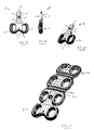
- Figure 1 shows an embodiment of the extension plate;
- Figure 2 shows a side view of the extension plate of Figure 1;
- Figure 3 shows an end view of the extension plate of Figure 1;
- Figure 4 shows a perspective view of the extension plate of Figure 1;
- Figure 5 shows a further embodiment of the extension plate;
- Figure 6 shows a side view of the extension plate of Figure 5;
- Figure 7 shows an end view of the extension plate of Figure 5;
- Figure 8 shows a perspective view of the extension plate of Figure 5;
- Figure 9 shows a further embodiment of the extension plate;
- Figure 10 shows a side view of the extension plate of Figure 9;
- Figure 11 shows an end view of the extension plate of Figure 9;
- Figure 12 shows a perspective view of the extension plate of Figure 9;
- Figure 13 shows a perspective view of the extension plate attached to a bone segment;
- Figure 14 shows a side view of the extension plate attached to a second osteosynthesis plate;
- Figure 15 shows a bottom perspective view of the extension plate attached to a second osteosynthesis plate;
- Figure 16 shows a top view of the extension plate attached to a second osteosynthesis plate;
- Figure 17 shows an end perspective view of the extension plate attached to a second osteosynthesis plate; and
- Figure 18 shows a perspective view of the extension plate attached to a second osteosynthesis plate.
- Figure 19 shows a further embodiment of the extension plate;
- Figure 20 shows a side view of the extension plate of Figure 19;
- Figure 21 shows a perspective view of the extension plate of Figure 19;
- Figure 22 shows a perspective view of the extension plate of Figure 19 attached to a second osteosynthesis plate;
- Figure 23 shows a further embodiment of the extension plate of Figure 19;
- Figure 24 shows a further embodiment of the extension plate;
- Figure 25 shows a side view of the extension plate of Figure 24;
- Figure 26 shows a perspective view of the extension plate of Figure 24;
- Figure 27 shows a perspective view of the extension plate of Figure 24 attached to a second osteosynthesis plate;
- Figure 28 shows a further embodiment of the extension plate of Figure 24;
- Figure 29 shows a perspective view of the extension plate of Figure 28 attached to a second osteosynthesis plate;
- Figure 30 shows a further embodiment of the extension plate;
- Figure 31 shows a perspective view of the extension plate of Figure 30;
- Figure 32 shows a perspective view of the extension plate of Figure 30 attached to a second osteosynthesis plate;
-
- The invention relates to a method and apparatus for immobilizing adjacent bone segments. An osteosynthesis plating system is provided for fixing or immobilizing several pieces or segments of bone utilizing screws which may be screwed into the segments of bone through openings provided in the osteosynthesis plate. The osteosynthesis plate is pressed against the bone surface by the screws and fixed thereto. In particular, the invention relates to an osteosynthesis extension plate for immobilizing adjacent segments of bone in a second surgery wherein the removal of a previously implanted osteosynthesis plate is avoided. In this manner the disadvantages associated with removal of the previously implanted plate are avoided.
- Therefore, the advantages provided by the present invention include a reduction in surgery time and a less invasive surgical procedure. In addition, the cost associated with the extension plate is lower compared to a longer replacement plate. Surgical costs are decreased as well due to the reduction in surgical time required.
- Figure 1 shows a particular embodiment of the
osteosynthesis extension plate 1. Theextension plate 1 is provided for immobilizing at least two adjacent bone segments by means of screws which may be screwed into the bone segments throughopenings longitudinal edges transverse edges extension plate 1 has a firstbone contacting surface 40 and a secondnon-bone contacting surface 41. The extension plate is further defined by athick plate portion 50 and athin plate portion 51. At least two rows of pairs of through openings are provided in the extension plate. - As shown in Figure 1, a first pair of through
openings 12 is arranged in thethick portion 50 of the plate and a second pair of throughopenings 10 is arranged in thethin portion 51 of the plate such that the thin portion of theplate 51 can be inserted underneath and affixed between a second osteosynthesis plate and a bone segment. Thethick portion 50 of the extension plate is affixed to an adjacent bone segment by screws, thereby immobilizing an adjacent bone segment. - In a further embodiment of the invention, the
thin portion 51 of the extension plate can be positioned underneath the thick portion of anidentical extension plate 1 to provide for immobilization of adjacent bone segments. In this manner several identical extension plates can be piggybacked by placing thethin portion 51 of one extension plate underneath thethick portion 50 of another extension plate to immobilize several adjacent bone segments. - A small through
hole 5 may be provided to allow insertion of a positioning pin or tack through theextension plate 1 into the bone segment to temporarily secure the positioning of the extension plate while the screw holes are marked on the bone segment or drilled into the bone segment. - In another embodiment of the invention as shown in Figure 3, the
extension plate 1 is curved in the direction transverse to its longitudinal axis such that the firstbone contacting surface 40 is concave. Such a configuration of the firstbone contacting surface 40 allows for better contact with the surface of the bone segment to be immobilized. - In a further embodiment of the invention, the
osteosynthesis extension plate 1 is used to immobilize bone segments during a second surgery where a previously implanted osteosynthesis plate is already affixed to an adjacent bone segment. In this embodiment, the screws holding the previously implanted plate to the adjacent bone segment are removed and thethin portion 51 of theextension plate 1 is inserted underneath the previously implanted plate such that the screw holes of the previously implanted plate and the screw holes 10 of thethin portion 51 of the extension plate are in alignment. Screws are then reinserted into the bone segment through the previously implanted plate and thethin portion 51 of the extension plate. Thethick portion 50 of the extension plate is screwed into the adjacent bone segment thereby immobilizing the adjacent bone segment. In this manner, a bone segment adjacent to a previously injured and immobilized bone segment can be immobilized without completely removing a previously implanted plate. In other words, only the screws holding the previously implanted plate to the adjacent bone segment are removed, not all screws holding the previously implanted plate to all the previously immobilized bone segments need be removed. A perspective view of the extension plate of Figure 1 is shown in Figure 4. - In a further embodiment of the invention, the through
openings - In another embodiment of the invention as shown in Figure 5, the elongated slots arranged in the
thin portion 51 of the plate are open-ended slots 10' at thetransverse edge 30 of thethin portion 51 of the plate. Such a configuration enables theextension plate 1 to be affixed between a bone segment and a previously implanted plate without complete removal of the bone screws of the previously implanted plates. In such a configuration, the screws holding the previously implanted plate to the bone segment adjacent to the injured bone segment need only be loosened such that thethin portion 51 of the extension plate can be slid into position. Theextension plate 1 is inserted between the bone segment and the previously implanted plate such that the open-ended slots 10' of thethin portion 51 of the extension plate fit around the loosened screws of the previously implanted plate. The screws are then re-tightened and the thick portion of theextension plate 50 is screwed into the adjacent bone segment. In this manner, a bone segment adjacent to a previously injured and immobilized bone segment can be immobilized without completely removing the screws from a previously implanted plate. - A side view of the extension plate of Figure 5 is shown in Figure 6. An end view is shown in Figure 7 and a perspective view is shown in Figure 8.
- In a further embodiment of the invention, the open-ended slots 10' have beveled edges for ease of insertion underneath a previously implanted plate.
- In a further embodiment of the invention as shown in Figure 9, the
thick portion 50 of the extension plate may have more than one row of throughopenings 12 for immobilization of more than one adjacent bone segment. In this embodiment, theextension plate 1 has a greater longitudinal dimension in order to extend over more than one adjacent bone segment. Pairs of holes are positioned such that each adjacent bone segment can be affixed by two bone screws. The number of adjacent bone segments that can be immobilized in this manner may be two, three, four or more. A side view of the extension plate of Figure 9 is shown in Figure 10. An end view is shown in Figure 11 and a perspective view is shown in Figure 12. - Figure 13 shows a perspective view of the
extension plate 1 attached to abone segment 2 and inserted between a previously implantedbone plate 100 and anadjacent bone segment 101. Theextension plate 1 in Figure 13 may include any of the embodiments described herein. The previously implanted bone plate is shown attached to threebone segments - Figure 14 shows a side view of an
extension plate 1 connected to a previously implantedbone plate 100. Thethin portion 51 of the extension plate is shown inserted underneath the previously implantedbone plate 100 such that the bone screws 110 can be inserted through the screw holes of the previously implantedplate 100 and the screw holes or open-ended slots of theextension plate 1. - Figure 15 provides a bottom view of the configuration of Figure 14. In the embodiment shown, the
extension plate 1 has elongatedslots 10. However, any of the embodiments discussed above may be used in this configuration, including the open-ended slot configuration of Figure 5. Figure 15 more clearly shows the alignment of thescrews 110. Figure 16 shows a top view of the Figure 15 embodiment. In Figure 16 the positioning of thethin portion 51 of theextension plate 1 underneath the previously implantedplate 100 can be seen. Figure 17 shows an end view of this configuration and Figure 18 shows a perspective view. - In another embodiment of the invention as shown in Figure 19, the
thin plate portion 51 of theextension plate 1 is provided withside rails 60 arranged at thelongitudinal edges thin plate portion 51 which side rails extend above the secondnon-bone contacting surface 41 of theextension plate 1. A side view of the extension plate of Figure 19 is shown in Figure 20 and a perspective view is shown in Figure 21. As shown in Figure 22, when theextension plate 1 is positioned underneath thesecond osteosynthesis plate 100 the side rails 60 are substantially parallel to edgesurfaces 120 of thesecond osteosynthesis plate 100. The side rails 60 act to increase the bending strength of theextension plate 1 and enable a close fit with thesecond osteosynthesis plate 100. - Figure 23 shows an alternate embodiment of the extension plate shown in Figure 19. The side rails 60 may have ridges 61 which can interlock with grooves cut into the edge surfaces 120 of the
second osteosynthesis plate 100. - In an alternate embodiment of the invention as shown in Figure 24, the
extension plate 1 is generally defined by contoured longitudinal edges 20', 21' and contoured transverse edges 30', 31'. Thethick plate portion 50 has at least one row of pairs of throughopenings 12. The thin plate portion 51' has at least one throughopening 11. Thethick plate portion 50 has a substantially larger transverse dimension than the thin plate portion 51'. A side view of theplate 1 of Figure 24 is shown in Figure 25 and a perspective view is shown in Figure 26. As shown in Figure 27, the thin plate portion 51' is dimensioned to fit within agroove 130 provided in anon-bone contacting surface 140 of asecond osteosynthesis plate 100. Such an arrangement reduces the overall thickness of the implant as the thin plate portion 51' fits substantially within thegroove 130 provided in thesecond plate 100. In addition, with the extension plate of Figure 24, there is no need to remove or loosen the screws holding the previously implantedsecond plate 100 as the extension plate fits in agroove 130 on thenon-bone contacting surface 140 of thesecond plate 100. The extension plate may be affixed to thesecond plate 100 by means of a screw through theopening 11 and to the adjacent bone segment by means of screws through theopenings 12. - Alternatively, the thin plate portion 51' of the
extension plate 1 of Figure 24 may comprise a T-shapedportion 55 extending from the thin plate portion 51' as shown in Figure 28. As shown in Figure 29, the T-shapedportion 55 fits within a corresponding groove 130' in anon-bone contacting surface 140 of thesecond plate 100. - In a further embodiment shown in Figure 30, the extension plate has a
plate portion 52 having at least one row of pairs of throughopenings 12 with twoextension arms 9 extending longitudinally from theplate portion 52. A perspective view of the extension plate of Figure 30 is shown in Figure 31. As shown in Figure 32, theextension arms 9 are dimensioned to fit alongside asecond osteosynthesis plate 100. Theplate portion 52 can be affixed to thesecond osteosynthesis plate 100 by adevice 18 such as a clamp or similar device and to an adjacent bone segment by screws. Such an arrangement provides the required stiffness and stability under flexion and extension of the bone segments. With such an arrangement, there is no need to loosen or remove any screws from the previously implantedbone plate 100. With the extension plate of Figure 30, it may be necessary to cut a small channel or groove in the bone segment alongside the previously implantedbone plate 100 to provide room for theextension arms 9. Such a groove or channel can be cut in the bone segment using a high speed burr or similar instrument. - Multiple extension plates may be used to immobilize multiple adjacent bone segments.
- It will now be appreciated that the present invention provides an improved method and apparatus for fixing or immobilizing several pieces or segments of bone utilizing screws which may be screwed into the segments of bone through openings provided in the osteosynthesis plate. In particular, the invention provides an improved method and apparatus for immobilizing adjacent segments of bone in a second surgery wherein the removal of a previously implanted osteosynthesis plate is avoided. In this manner the disadvantages associated with removal of the previously implanted plate are avoided.
- Although the invention has been described in connection with preferred embodiments thereof, those skilled in the art will appreciate that numerous adaptations and modifications may be made thereto without departing from the spirit and scope of the invention, as set forth in the following claims.
Claims (13)
- An osteosynthesis extension plate for immobilizing at least two adjacent bone segments by means of screws which may be screwed into the bone segments through openings in the extension plate, wherein the extension plate comprises:wherein a first pair of through openings is arranged in the thick plate portion and a second pair of through openings is arranged in the thin plate portion such that the thin plate portion can be inserted underneath and affixed between a second osteosynthesis plate and a bone segment.longitudinal edges;transverse edges;a first bone contacting surface;a second non-bone contacting surface;a thick plate portion;a thin plate portion; andat least two rows of pairs of through openings,
- An extension plate in accordance with claim 1, wherein the thin plate portion of the extension plate can be positioned underneath a thick portion of an identical extension plate to provide for immobilization of adjacent bone segments.
- An extension plate in accordance with claim 1 or 2,
wherein the extension plate is curved in the direction transverse to its longitudinal axis such that the first bone contacting surface is concave. - An extension plate in accordance with one of the preceding claims, wherein the second osteosynthesis plate is a previously implanted plate.
- An extension plate in accordance with one of the preceding claims, wherein at least two rows of pairs of through openings are arranged in the thick plate portion for immobilization of at least two adjacent bone segments.
- An extension plate in accordance with one of the preceding claims, wherein the through openings are elongated slots.
- An extension plate in accordance with claim 6, wherein the slots arranged in the thin plate portion are open-ended at the transverse edge of the thin plate portion.
- An extension plate in accordance with claim 7, wherein the open-ended slots have beveled edges for ease of insertion underneath a previously implanted plate.
- An extension plate in accordance with one of the preceding claims, further comprising side rails arranged at the longitudinal edges of the thin plate portion and extending above the second non-bone contacting surface such that the side rails are substantially parallel to edge surfaces of the second osteosynthesis plate when said extension plate is positioned underneath the second osteosynthesis plate.
- An extension plate in accordance with claim 9, wherein the side rails interlock with grooves cut into the edge surfaces of the second osteosynthesis plate.
- An osteosynthesis extension plate for immobilizing at least two adjacent bone segments by means of screws which may be screwed into the bone segments through openings in the extension plate, wherein the extension plate comprises:wherein the thick plate portion has a substantially larger transverse dimension than the thin plate portion, said thin plate portion being dimensioned to fit within a groove provided in a non-bone contacting surface of a second osteosynthesis plate such that the thin plate portion can be affixed to the second osteosynthesis plate without the need to remove existing screws affixing the second osteosynthesis plate.contoured longitudinal edges;contoured transverse edges;a first bone contacting surface;a second non-bone contacting surface;a thick plate portion having at least one row of pairs of through openings; anda thin plate portion having at least one through opening;
- An extension plate in accordance with claim 11, further comprising:a T-shaped portion extending from the thin plate portion.
- An osteosynthesis extension plate for immobilizing at least two adjacent bone segments by means of screws which may be screwed into the bone segments through openings in the extension plate, wherein the extension plate comprises:contoured longitudinal edges;contoured transverse edges;a first bone contacting surface;a second non-bone contacting surface;a plate portion having at least one row of pairs of through openings; andtwo extension arms extending longitudinally from the plate portion, said arms being dimensioned to fit alongside a second osteosynthesis plate;said extension plate adapted to be affixed to the second osteosynthesis plate by a clamping device.
Applications Claiming Priority (2)
| Application Number | Priority Date | Filing Date | Title |
|---|---|---|---|
| US70880600A | 2000-11-08 | 2000-11-08 | |
| US708806 | 2000-11-08 |
Publications (2)
| Publication Number | Publication Date |
|---|---|
| EP1205154A2 true EP1205154A2 (en) | 2002-05-15 |
| EP1205154A3 EP1205154A3 (en) | 2003-04-02 |
Family
ID=24847256
Family Applications (1)
| Application Number | Title | Priority Date | Filing Date |
|---|---|---|---|
| EP01125972A Withdrawn EP1205154A3 (en) | 2000-11-08 | 2001-10-31 | Osteosynthesis plating apparatus and method with extension plate |
Country Status (2)
| Country | Link |
|---|---|
| US (1) | US6645208B2 (en) |
| EP (1) | EP1205154A3 (en) |
Cited By (6)
| Publication number | Priority date | Publication date | Assignee | Title |
|---|---|---|---|---|
| WO2007127628A2 (en) * | 2006-04-26 | 2007-11-08 | Warsaw Orthopedic, Inc. | Revision fixation and method of use |
| US7635364B2 (en) | 2004-12-01 | 2009-12-22 | Synthes Usa, Llc | Unidirectional translation system for bone fixation |
| US7666185B2 (en) | 2003-09-03 | 2010-02-23 | Synthes Usa, Llc | Translatable carriage fixation system |
| US7857839B2 (en) | 2003-09-03 | 2010-12-28 | Synthes Usa, Llc | Bone plate with captive clips |
| US7909860B2 (en) | 2003-09-03 | 2011-03-22 | Synthes Usa, Llc | Bone plate with captive clips |
| EP2494933A3 (en) * | 2002-02-01 | 2013-10-30 | Zimmer Spine, Inc. | Spinal plate system for stabilizing a portion of a spine |
Families Citing this family (74)
| Publication number | Priority date | Publication date | Assignee | Title |
|---|---|---|---|---|
| US20050010227A1 (en) * | 2000-11-28 | 2005-01-13 | Paul Kamaljit S. | Bone support plate assembly |
| US6503250B2 (en) * | 2000-11-28 | 2003-01-07 | Kamaljit S. Paul | Bone support assembly |
| US6666867B2 (en) * | 2001-02-15 | 2003-12-23 | Fast Enetix, Llc | Longitudinal plate assembly having an adjustable length |
| US7097645B2 (en) * | 2001-06-04 | 2006-08-29 | Sdgi Holdings, Inc. | Dynamic single-lock anterior cervical plate system having non-detachably fastened and moveable segments |
| EP1404243A4 (en) | 2001-06-04 | 2010-05-19 | Warsaw Orthopedic Inc | Dynamic anterior cervical plate system having moveable segments, instrumentation, and method for installation thereof |
| AU2002322028C1 (en) | 2001-06-04 | 2008-06-26 | Warsaw Orthopedic, Inc. | Anterior cervical plate system having vertebral body engaging anchors, connecting plate, and method for installation thereof |
| US7186256B2 (en) * | 2001-06-04 | 2007-03-06 | Warsaw Orthopedic, Inc. | Dynamic, modular, single-lock anterior cervical plate system having assembleable and movable segments |
| US7041105B2 (en) * | 2001-06-06 | 2006-05-09 | Sdgi Holdings, Inc. | Dynamic, modular, multilock anterior cervical plate system having detachably fastened assembleable and moveable segments |
| US7044952B2 (en) | 2001-06-06 | 2006-05-16 | Sdgi Holdings, Inc. | Dynamic multilock anterior cervical plate system having non-detachably fastened and moveable segments |
| US7303564B2 (en) * | 2002-02-01 | 2007-12-04 | Spinal Concepts, Inc. | Spinal plate extender system and method |
| US9101422B2 (en) * | 2002-02-01 | 2015-08-11 | Zimmer Spine, Inc. | Spinal plate system for stabilizing a portion of a spine |
| US7001389B1 (en) | 2002-07-05 | 2006-02-21 | Navarro Richard R | Fixed and variable locking fixation assembly |
| US8613772B2 (en) * | 2003-04-21 | 2013-12-24 | Rsb Spine Llc | Lateral mount implant device |
| US6984234B2 (en) | 2003-04-21 | 2006-01-10 | Rsb Spine Llc | Bone plate stabilization system and method for its use |
| US20170020683A1 (en) | 2003-04-21 | 2017-01-26 | Rsb Spine Llc | Bone plate stabilization system and method for its use |
| FR2855041B1 (en) * | 2003-05-23 | 2006-02-24 | Hassan Razian | PLATE FOR OSTEOSYNTHESIS SYSTEM |
| US7942913B2 (en) | 2004-04-08 | 2011-05-17 | Ebi, Llc | Bone fixation device |
| FR2870711B1 (en) * | 2004-05-26 | 2006-09-01 | Sdgi Holdings Inc | DEVICE FOR CONNECTING THE ROD OF A SPINAL OSTEOSYNTHESIS DEVICE TO A VERTEBRA, AND A OSTEOSYNTHESIS DEVICE COMPRISING SAME |
| US7604638B2 (en) * | 2004-06-21 | 2009-10-20 | Depuy Spine, Inc. | Instruments and methods for holding a bone plate |
| US9615866B1 (en) | 2004-10-18 | 2017-04-11 | Nuvasive, Inc. | Surgical fixation system and related methods |
| US7621914B2 (en) * | 2004-10-28 | 2009-11-24 | Biodynamics, Llc | Adjustable bone plate |
| US8062296B2 (en) * | 2005-03-17 | 2011-11-22 | Depuy Products, Inc. | Modular fracture fixation plate system with multiple metaphyseal and diaphyseal plates |
| US8394130B2 (en) | 2005-03-17 | 2013-03-12 | Biomet C.V. | Modular fracture fixation system |
| EP1814474B1 (en) | 2004-11-24 | 2011-09-14 | Samy Abdou | Devices for inter-vertebral orthopedic device placement |
| US7736380B2 (en) | 2004-12-21 | 2010-06-15 | Rhausler, Inc. | Cervical plate system |
| US7527640B2 (en) | 2004-12-22 | 2009-05-05 | Ebi, Llc | Bone fixation system |
| US8470039B2 (en) | 2005-03-17 | 2013-06-25 | Spinal Elements, Inc. | Flanged interbody fusion device with fastener insert and retaining ring |
| US20060271052A1 (en) * | 2005-05-12 | 2006-11-30 | Stern Joseph D | Revisable anterior cervical plating system |
| US8070749B2 (en) | 2005-05-12 | 2011-12-06 | Stern Joseph D | Revisable anterior cervical plating system |
| US20070010818A1 (en) * | 2005-07-06 | 2007-01-11 | Stone Howard A | Surgical system for joints |
| DE102005044532A1 (en) * | 2005-09-16 | 2007-04-05 | Ulrich Gmbh & Co. Kg | Ventral plate |
| US7955364B2 (en) | 2005-09-21 | 2011-06-07 | Ebi, Llc | Variable angle bone fixation assembly |
| US7862591B2 (en) * | 2005-11-10 | 2011-01-04 | Warsaw Orthopedic, Inc. | Intervertebral prosthetic device for spinal stabilization and method of implanting same |
| US20070173842A1 (en) * | 2005-11-29 | 2007-07-26 | Abdou M S | Device and Method for the Placement of Spinal Fixators |
| US20070185489A1 (en) * | 2006-01-26 | 2007-08-09 | Abdou M S | Devices and Methods for Inter-Vertebral Orthopedic Device Placement |
| US7867261B2 (en) * | 2006-03-17 | 2011-01-11 | Depuy Products, Inc. | Bone plate with variable torsional stiffness at fixed angle holes |
| US20080033438A1 (en) * | 2006-08-04 | 2008-02-07 | Roy Frizzell | Cervical Saddle Plate |
| US20080039847A1 (en) * | 2006-08-09 | 2008-02-14 | Mark Piper | Implant and system for stabilization of the spine |
| US8262710B2 (en) * | 2006-10-24 | 2012-09-11 | Aesculap Implant Systems, Llc | Dynamic stabilization device for anterior lower lumbar vertebral fusion |
| US8206390B2 (en) * | 2006-11-02 | 2012-06-26 | Warsaw Orthopedic, Inc. | Uni-directional ratcheting bone plate assembly |
| US9072548B2 (en) * | 2007-06-07 | 2015-07-07 | Anthem Orthopaedics Llc | Spine repair assembly |
| US20090043341A1 (en) * | 2007-08-09 | 2009-02-12 | Aesculap, Inc. | Dynamic extension plate for anterior cervical fusion and method of installation |
| US9345517B2 (en) | 2008-02-02 | 2016-05-24 | Globus Medical, Inc. | Pedicle screw having a removable rod coupling |
| US8414584B2 (en) | 2008-07-09 | 2013-04-09 | Icon Orthopaedic Concepts, Llc | Ankle arthrodesis nail and outrigger assembly |
| WO2010006195A1 (en) | 2008-07-09 | 2010-01-14 | Amei Technologies, Inc. | Ankle arthrodesis nail and outrigger assembly |
| US8840647B2 (en) * | 2008-08-05 | 2014-09-23 | The Cleveland Clinic Foundation | Facet augmentation |
| US8740951B2 (en) * | 2008-09-04 | 2014-06-03 | Bullard Spine, Llc | Anterior cervical instrumentation systems, methods and devices |
| US9220547B2 (en) | 2009-03-27 | 2015-12-29 | Spinal Elements, Inc. | Flanged interbody fusion device |
| US8808333B2 (en) | 2009-07-06 | 2014-08-19 | Zimmer Gmbh | Periprosthetic bone plates |
| US8834532B2 (en) * | 2009-07-07 | 2014-09-16 | Zimmer Gmbh | Plate for the treatment of bone fractures |
| USD754857S1 (en) | 2009-10-14 | 2016-04-26 | Nuvasive, Inc. | Bone plate |
| US8764806B2 (en) | 2009-12-07 | 2014-07-01 | Samy Abdou | Devices and methods for minimally invasive spinal stabilization and instrumentation |
| US8500782B2 (en) | 2010-07-22 | 2013-08-06 | Aesculap Implant Systems, Llc | Semi-dynamic fixation plate system |
| US9095387B2 (en) | 2011-04-13 | 2015-08-04 | Globus Medical, Inc. | Spine stabilization |
| US8771324B2 (en) | 2011-05-27 | 2014-07-08 | Globus Medical, Inc. | Securing fasteners |
| US8845728B1 (en) | 2011-09-23 | 2014-09-30 | Samy Abdou | Spinal fixation devices and methods of use |
| US11123117B1 (en) * | 2011-11-01 | 2021-09-21 | Nuvasive, Inc. | Surgical fixation system and related methods |
| US20130226240A1 (en) | 2012-02-22 | 2013-08-29 | Samy Abdou | Spinous process fixation devices and methods of use |
| US9198767B2 (en) | 2012-08-28 | 2015-12-01 | Samy Abdou | Devices and methods for spinal stabilization and instrumentation |
| US9320617B2 (en) | 2012-10-22 | 2016-04-26 | Cogent Spine, LLC | Devices and methods for spinal stabilization and instrumentation |
| WO2015123693A1 (en) * | 2014-02-14 | 2015-08-20 | Spectrum Spine Ip Holdings, Llc | Cervical minimal access fusion system |
| US9962204B2 (en) * | 2014-04-12 | 2018-05-08 | Seyed Alireza Mirghasemi | Modular bone plate |
| AU2016212009C1 (en) | 2015-01-27 | 2021-02-25 | Spinal Elements, Inc. | Facet joint implant |
| WO2016127060A1 (en) * | 2015-02-05 | 2016-08-11 | Paragon 28, Inc. | Bone plates, systems, and methods of use |
| US10363072B2 (en) | 2015-02-18 | 2019-07-30 | Degen Medical, Inc. | Vertebral plate revision apparatuses, kits, and methods and osteosynthesis systems |
| US9615931B2 (en) * | 2015-03-20 | 2017-04-11 | Globus Medical, Inc. | Surgical plate systems |
| US10857003B1 (en) | 2015-10-14 | 2020-12-08 | Samy Abdou | Devices and methods for vertebral stabilization |
| US10744000B1 (en) | 2016-10-25 | 2020-08-18 | Samy Abdou | Devices and methods for vertebral bone realignment |
| US10973648B1 (en) | 2016-10-25 | 2021-04-13 | Samy Abdou | Devices and methods for vertebral bone realignment |
| US10828071B2 (en) | 2017-02-21 | 2020-11-10 | Avery M. Jackson | Hinged anterior cervical locking plate system |
| CA3111008A1 (en) | 2018-09-20 | 2020-03-26 | Spinal Elements, Inc. | Spinal implant device |
| US11179248B2 (en) | 2018-10-02 | 2021-11-23 | Samy Abdou | Devices and methods for spinal implantation |
| EP4054452A1 (en) | 2019-11-07 | 2022-09-14 | Freedom Innovations, LLC | Implantable modular orthopedic plate system |
| WO2022109524A1 (en) | 2020-11-19 | 2022-05-27 | Spinal Elements, Inc. | Curved expandable interbody devices and deployment tools |
Citations (6)
| Publication number | Priority date | Publication date | Assignee | Title |
|---|---|---|---|---|
| US2486303A (en) * | 1948-04-29 | 1949-10-25 | Harry Herschel Leiter | Surgical appliance for bone fractures |
| US4503848A (en) * | 1981-04-08 | 1985-03-12 | Aesculap-Werke Aktiengesellschaft | Osteosynthesis plate |
| DE8624671U1 (en) * | 1986-09-15 | 1986-10-23 | Waldemar Link Gmbh & Co, 2000 Hamburg | Osteosynthesis plate |
| DE4340398A1 (en) * | 1993-11-26 | 1995-06-01 | Jeffrey D Dr Fairley | Assembly for securing broken mobile bones in a single plane |
| US5616142A (en) * | 1994-07-20 | 1997-04-01 | Yuan; Hansen A. | Vertebral auxiliary fixation device |
| EP0773004A1 (en) * | 1995-11-07 | 1997-05-14 | IMPLANTS ORTHOPEDIQUES TOUTES APPLICATIONS, S.A.R.L. dite: | Osteotomy plate for angle correction |
Family Cites Families (4)
| Publication number | Priority date | Publication date | Assignee | Title |
|---|---|---|---|---|
| US5261910A (en) * | 1992-02-19 | 1993-11-16 | Acromed Corporation | Apparatus for maintaining spinal elements in a desired spatial relationship |
| WO1996005778A1 (en) * | 1994-08-23 | 1996-02-29 | Spinetech, Inc. | Cervical spine stabilization system |
| US6139550A (en) * | 1997-02-11 | 2000-10-31 | Michelson; Gary K. | Skeletal plating system |
| US5951557A (en) * | 1997-12-30 | 1999-09-14 | Luter; Dennis W. | Bone plate |
-
2001
- 2001-10-31 EP EP01125972A patent/EP1205154A3/en not_active Withdrawn
-
2002
- 2002-09-03 US US10/234,647 patent/US6645208B2/en not_active Expired - Lifetime
Patent Citations (6)
| Publication number | Priority date | Publication date | Assignee | Title |
|---|---|---|---|---|
| US2486303A (en) * | 1948-04-29 | 1949-10-25 | Harry Herschel Leiter | Surgical appliance for bone fractures |
| US4503848A (en) * | 1981-04-08 | 1985-03-12 | Aesculap-Werke Aktiengesellschaft | Osteosynthesis plate |
| DE8624671U1 (en) * | 1986-09-15 | 1986-10-23 | Waldemar Link Gmbh & Co, 2000 Hamburg | Osteosynthesis plate |
| DE4340398A1 (en) * | 1993-11-26 | 1995-06-01 | Jeffrey D Dr Fairley | Assembly for securing broken mobile bones in a single plane |
| US5616142A (en) * | 1994-07-20 | 1997-04-01 | Yuan; Hansen A. | Vertebral auxiliary fixation device |
| EP0773004A1 (en) * | 1995-11-07 | 1997-05-14 | IMPLANTS ORTHOPEDIQUES TOUTES APPLICATIONS, S.A.R.L. dite: | Osteotomy plate for angle correction |
Cited By (12)
| Publication number | Priority date | Publication date | Assignee | Title |
|---|---|---|---|---|
| EP2494933A3 (en) * | 2002-02-01 | 2013-10-30 | Zimmer Spine, Inc. | Spinal plate system for stabilizing a portion of a spine |
| US7666185B2 (en) | 2003-09-03 | 2010-02-23 | Synthes Usa, Llc | Translatable carriage fixation system |
| US7857839B2 (en) | 2003-09-03 | 2010-12-28 | Synthes Usa, Llc | Bone plate with captive clips |
| US7909860B2 (en) | 2003-09-03 | 2011-03-22 | Synthes Usa, Llc | Bone plate with captive clips |
| US8262659B2 (en) | 2003-09-03 | 2012-09-11 | Synthes Usa, Llc | Translatable carriage fixation system |
| US9220548B2 (en) | 2003-09-03 | 2015-12-29 | DePuy Synthes Products, Inc. | Bone plate with captive clips |
| US10368927B2 (en) | 2003-09-03 | 2019-08-06 | DePuy Synthes Products, Inc. | Bone plate with captive clips |
| US7635364B2 (en) | 2004-12-01 | 2009-12-22 | Synthes Usa, Llc | Unidirectional translation system for bone fixation |
| WO2007127628A2 (en) * | 2006-04-26 | 2007-11-08 | Warsaw Orthopedic, Inc. | Revision fixation and method of use |
| WO2007127628A3 (en) * | 2006-04-26 | 2008-06-12 | Warsaw Orthopedic Inc | Revision fixation and method of use |
| WO2007127632A3 (en) * | 2006-04-26 | 2008-06-19 | Warsaw Orthopedic Inc | Revision fixation plate and method of use |
| JP2009535114A (en) * | 2006-04-26 | 2009-10-01 | ウォーソー・オーソペディック・インコーポレーテッド | Modified fixing plate |
Also Published As
| Publication number | Publication date |
|---|---|
| US6645208B2 (en) | 2003-11-11 |
| EP1205154A3 (en) | 2003-04-02 |
| US20030074001A1 (en) | 2003-04-17 |
Similar Documents
| Publication | Publication Date | Title |
|---|---|---|
| US6645208B2 (en) | Osteosynthesis plating apparatus and method with extension plate | |
| US11638598B2 (en) | Spine surgery device and method | |
| AU711026B2 (en) | Bone fixation device and method | |
| US5603714A (en) | Instrument for anterior correction of scoliosis or the like | |
| US20210121213A1 (en) | Orthopedic Implant In The Form Of A Plate To Be Fixed Between Two Bone Parts | |
| EP1667590B1 (en) | Bone plates | |
| US8491643B2 (en) | Anterior bone plate system and method of use | |
| EP0726064B1 (en) | Screw-rod-connector of an anterior spiral fixation device | |
| EP1885266B1 (en) | Spinous process stabilization devices | |
| KR101144067B1 (en) | Anatomical distal radius fracture fixation plate and methods of using the same | |
| EP2010082B1 (en) | Connector apparatus | |
| US20120095466A1 (en) | Orthopedic Plate Assembly for a Distal Radius Having Re-Contouring Features and Method for Using Same | |
| US20040193269A1 (en) | Anterior lumbar interbody fusion cage with locking plate | |
| AU2008230056A1 (en) | Slidable bone plate system | |
| CA2537761A1 (en) | Method for the correction of spinal deformities using rod-plates anterior system | |
| GB2331244A (en) | Fracture fixation devices | |
| US11707308B2 (en) | Implant positioner and sternal plating system | |
| CA2240013C (en) | Bone fixation device and method | |
| EP0027726A1 (en) | Improved orthopedic fixation pin holder | |
| US20090287256A1 (en) | Vertebral fixation plate and screw assembly |
Legal Events
| Date | Code | Title | Description |
|---|---|---|---|
| PUAI | Public reference made under article 153(3) epc to a published international application that has entered the european phase |
Free format text: ORIGINAL CODE: 0009012 |
|
| AK | Designated contracting states |
Kind code of ref document: A2 Designated state(s): AT BE CH CY DE DK ES FI FR GB GR IE IT LI LU MC NL PT SE TR |
|
| AX | Request for extension of the european patent |
Free format text: AL;LT;LV;MK;RO;SI |
|
| PUAL | Search report despatched |
Free format text: ORIGINAL CODE: 0009013 |
|
| AK | Designated contracting states |
Kind code of ref document: A3 Designated state(s): AT BE CH CY DE DK ES FI FR GB GR IE IT LI LU MC NL PT SE TR Designated state(s): AT BE CH CY DE DK ES FI FR GB GR IE IT LI LU MC NL PT SE TR |
|
| AX | Request for extension of the european patent |
Extension state: AL LT LV MK RO SI |
|
| RIC1 | Information provided on ipc code assigned before grant |
Ipc: 7A 61B 17/70 B Ipc: 7A 61B 17/80 A |
|
| AKX | Designation fees paid | ||
| REG | Reference to a national code |
Ref country code: DE Ref legal event code: 8566 |
|
| STAA | Information on the status of an ep patent application or granted ep patent |
Free format text: STATUS: THE APPLICATION IS DEEMED TO BE WITHDRAWN |
|
| 18D | Application deemed to be withdrawn |
Effective date: 20031003 |