EP1205762A1 - Method and apparatus for determining sound source - Google Patents
Method and apparatus for determining sound source Download PDFInfo
- Publication number
- EP1205762A1 EP1205762A1 EP00935570A EP00935570A EP1205762A1 EP 1205762 A1 EP1205762 A1 EP 1205762A1 EP 00935570 A EP00935570 A EP 00935570A EP 00935570 A EP00935570 A EP 00935570A EP 1205762 A1 EP1205762 A1 EP 1205762A1
- Authority
- EP
- European Patent Office
- Prior art keywords
- sound
- information
- sound sources
- sources
- sound source
- Prior art date
- Legal status (The legal status is an assumption and is not a legal conclusion. Google has not performed a legal analysis and makes no representation as to the accuracy of the status listed.)
- Granted
Links
Images


Classifications
-
- H—ELECTRICITY
- H04—ELECTRIC COMMUNICATION TECHNIQUE
- H04N—PICTORIAL COMMUNICATION, e.g. TELEVISION
- H04N7/00—Television systems
- H04N7/14—Systems for two-way working
- H04N7/15—Conference systems
-
- G—PHYSICS
- G01—MEASURING; TESTING
- G01S—RADIO DIRECTION-FINDING; RADIO NAVIGATION; DETERMINING DISTANCE OR VELOCITY BY USE OF RADIO WAVES; LOCATING OR PRESENCE-DETECTING BY USE OF THE REFLECTION OR RERADIATION OF RADIO WAVES; ANALOGOUS ARRANGEMENTS USING OTHER WAVES
- G01S5/00—Position-fixing by co-ordinating two or more direction or position line determinations; Position-fixing by co-ordinating two or more distance determinations
- G01S5/18—Position-fixing by co-ordinating two or more direction or position line determinations; Position-fixing by co-ordinating two or more distance determinations using ultrasonic, sonic, or infrasonic waves
Definitions
- the present invention relates to a sound source identifying apparatus and method for identifying various sounds individually based on image information and sound information derived from a plurality of such sound sources.
- the present invention has for its first object to provide a sound source identifying apparatus that is capable of identifying an object as a source of a sound in mixed sounds in terms of its location with greater accuracy by using both information as to the sound and information as to the sound source as an image thereof and using information as to that position to separate the sound from the mixed sounds with due accuracy.
- the present invention further has for its second object to provide a sound source identifying method that is capable of identifying an object as a source of a sound in mixed sounds in terms of its location with greater accuracy by using both information as to the sound and information as to the sound source as an image thereof and using information as to that position to separate the sound from the mixed sounds with due accuracy.
- a sound source identifying apparatus which apparatus comprises: a sound collecting means for capturing sounds from a plurality of sound sources with a pair of sound collecting microphones juxtaposed with each other across a preselected spacing and opposed to the sound sources and for processing the captured sounds; either or both of an imaging means and a sensing means, the imaging means being adapted to consecutively image objects that can be the said sound sources, the said sensing means being for sensing the said objects possibly being the said sources; an image processing means for deriving information as to locations of the said objects possibly being the said sound sources, from either or both of image pictures imaged by the said imaging means and directional information of the said objects sensed by the said sensing means; a sound processing means for localizing the positions of the said sound sources based on sound information of the said sounds captured by the said sound collecting means and position information derived by the said image processing means; and a control means for controlling operations of the said sound collecting means, the said imaging means and/or the
- the said sound processing means preferably includes directional filters, each of which is adapted to extract sound information at a particular time instant selectively.
- the said sound processing means preferably has a function to derive information as to rough directions in which said objects possibly being the sound sources are located.
- the said sensing means preferably is adapted to sense the said objects possibly being the said sound sources in response to magnetism thereof or an infrared ray therefrom.
- the said objects possibly being the said sound sources have each a material carrying magnetism attached thereto.
- the sound source identifying apparatus of the present invention in localizing the locations of sound sources according to the sound information acquired from the sound collecting microphones is designed to narrow the directions of the sound sources with reference to the position information based on the information as to image pictures imaged by the imaging means and the information as to the directions acquired by the sensing means.
- the sound source identifying apparatus of the present invention is made able to specify the each object that can be the sound sources by using dynamic image pictures and directional information of the objects and at the same time to individually separate the sound sources reliably by using their position information and sound information.
- a sound source identifying method which comprises: a first step of capturing sounds from a plurality of sound sources with a pair of sound collecting microphones juxtaposed with each other across a spacing and opposed to the sound sources and processing the captured sounds, in a sound collecting means; a second step, conducted concurrently with the first step, of consecutively imaging objects that can be the said sound sources and/or sensing directions in which the said objects are located; a third step of deriving information as to locations of the said objects possibly being the said sound sources, from either or both of image pictures imaged, and the directions sensed, in the second step; and a fourth step of localizing locations of the said sound sources based on sound information of the sounds collected in the first step and position information derived in the third step.
- the sound source identifying method preferably further includes a fifth step of deriving information as to rough locations of the said sound sources only from the sound information of the said sounds collected in the said first step, wherein the said third step includes narrowing in advance directions of the said sound sources based on the rough position information derived in the said fifth step, thereby deriving the said position information of the said objects possibly being the said sound sources.
- the said fifth step roughly derives the directions of the said sound sources from a difference between phases and a difference between intensities of each of the said sounds acquired by the said sound collecting microphones.
- the said position information of the said objects possibly being the said sound sources is derived in the said third step on the basis of either or both of a color and a shape of a said object.
- the said fourth step preferably localizes the locations of the said sound sources by selecting particular preset directional filters in response to the position information derived in the said third step.
- the locations of the said sound sources are localized in the said fourth or fifth step on the basis of a signal in each of frequency bands arbitrarily divided into based on the sound information obtained in the said first step.
- the said position information of a said object possibly being a said sound source is derived from a movement of the said object.
- a said direction is sensed in response to magnetism or an infrared ray.
- the sound source identifying method permits not only sound information of a plurality of sound sources to be derived from a sound collecting means made of the two sound collecting microphones opposed to the sound sources, but also image information of these sound sources to be derived from image pictures thereof imaged by an imaging means. Further, sensing the directions of the sound sources by magnetism or an infrared ray gives rise to direction sensing information.
- the sound processing means when the sound processing means is localizing the locations of the sound sources based on sound information, e.g., on the basis of a difference between phases and a difference between intensities in sound information acquired by the sound collecting microphones for each of the sound sources, the direction of each of the sound sources is narrowed with reference to position information derived for each of objects possibly being the sound sources by an image processing means, e.g., from its color, shape and/or movement based on either or both of the direction sensing information and the image information derived from the imaging means, thereby permitting the sound sources to be localized as to their locations on the basis of signals in various frequency bands, e.g., harmonic structures. Consequently, the method makes it unnecessary to process the sound information omnidirectionally or over all the directions in identifying the sound sources, makes it possible to identify the sound source with greater certainty, makes a lesser amount of processable information sufficient and makes it possible to reduce the time for processing.
- the ability to identify three or more sound sources with two sound collecting microphones in the sound collecting means makes it possible to effect accurate identification of the locations of sound sources in simple construction.
- the fifth step is included of deriving information as to rough locations of the sound sources only from the sound information of the sounds collected in the first step and that the third step includes narrowing in advance directions of the sound sources based on the rough position information derived in the fifth step, thereby deriving the position information of the objects possibly being the sound sources, then there results a reduction in the amount of information for processing in deriving the position information of the objects possibly being the sound sources based on the image information in the third step, which simplifies the processing.
- the fourth step localizes the locations of the sound sources by selecting particular preset directional filters in response to the position information derived in the third step to extract sound information from each of the sound sources, having each of the directional filters preset for extracting sound information from each of the sound sources located in the corresponding direction permits the processing to localize the locations of all the sound sources to go on smoothly.
- Fig. 1 shows a form of embodiment of the sound source identifying apparatus according to the present invention.
- the sound source identifying apparatus 10 includes a sound collecting means 11, an imaging means 12, an image processing means 13, a sound processing means 14 and a control means 15.
- the sound collecting means 11 is designed to capture sounds from a plurality of sound sources, for example, three talkers, with a pair of sound collecting microphones 11a and 11b juxtaposed with each other across a preselected spacing D as indicated in Fig. 1 and opposed to the sound sources and to process the captured sounds. While the disposition of these sound collecting microphones may be set in any suitable manner, in the example shown they are provided at opposite sides of the imaging means 12, namely at its right hand and left hand sides.
- the imaging means 12 is constituted, for example, of a CCD (charge coupled device) camera and is designed as shown in Fig. 2 to make image pictures of a plurality of sound sources, e.g., three talkers A, B, and C, consecutively.
- CCD charge coupled device
- the image processing means 13 is designed to derive information as to the locations of objects that can be sound sources, in images taken by the imaging means 12, and based on their color, shape or movement. It should be noted here that the term “movement” is intended to include vibrations.
- the image processing means 13 sets up in and for the image picture taken by the imaging means 12, frames A1, B1 and C1 for the three talkers A, B and C according to the color (i.e., the color of the skin of a human being) and height as shown in Fig. 3(B). Then, as shown in Fig. 3(C) the image processing means 13 selects center points A2, B2 and C2 of these frames A1, B1 and C1 (indicated in Fig. 3 by the + marks) as the respective locations of the objects to be possibly sound sources and takes their respective horizontal coordinates A3, B3 and C3 as information of these positions.
- the image processing means 13 prior thereto should have rough directions A0, B0 and C0 of these sound sources (see Fig. 3(A)) entered therein that are determined by the sound processing means 14 to be described in detail below.
- the image processing means 13 derives information A3, B3 and C3 as to the respective locations as mentioned above of the objects that can be the sound sources by effecting the image processing within the narrowed regions of the rough directions A0, B0 and C0.
- the sound processing means 14 is designed to localize the locations of the sound sources based, for example, on the sound information derived from the microphones in the sound collecting means 11 and the position information A3, B3 and C3 derived by the image processing means 13.
- the sound information may be based on a difference in phase and a difference in intensity between two pieces of sound information received by the right hand side and left hand side sound collecting microphones 11a and 11b, respectively.
- the sound processing means 14 here effects processing as mentioned above over the entire ranges of angles: -90 degrees ⁇ ⁇ ⁇ +90 degrees.
- the processing operation may be lightened by, for example, processing every angular interval, e.g., 5 degrees of ⁇ .
- the sound processing means 15 first selects or determines rough directions A0, B0 and C0 of the sound sources based on sound information left and right from the sound collecting means 11. This follows the conventional sound source identifying technique yielding an accuracy of ⁇ 10 degrees.
- the sound processing means 14 outputs these rough directions A0, B0 and C0 for entry into the image processing means 13.
- the sound processing means 14 with reference to the position information A3, B3 and C3 entered therein from the image processing means 13 localizes the locations of the sound sources based again on the sound information narrowed into the ranges of the position information A3, B3 and C3, namely in the ranges of the position information A3, B3 and C3.
- the sound processing means 14 localizes the locations of the sound sources by making an appropriate choice of what are called directional filters for the sound sources A, B and C, respectively.
- such directional filters are stored as in a control table for the directions of the sound sources in an auxiliary storage means (not shown) in the control means 15, and are identified and selected as appropriate by the sound processing means 14 from the auxiliary storage means based on the position information A3, B3 and C3 from the image processing means 13.
- the control means 15 that may, for example, be comprised of a computer is designed to control the operations of the sound collecting means 11, the imaging means 12, the image processing means 13 and the sound processing means 14.
- the control means 15 as mentioned above has the directional filters stored as preset in the auxiliary storage means (not shown) therein.
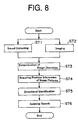
- the sound source identifying apparatus 10 operates as described below, in accordance with the flow chart shown in Fig. 8.
- step ST1 the control means 15 acts on the sound collecting means 11 to cause each of the sound collecting microphones 11a and 11b to collect sound from sound sources A, B and C, while in the mean time the control means 15 also acts on the imaging means 12 to cause it to image the sound sources consecutively in step ST2.
- step ST3 the control means 15 acts on the sound processing means 14 to cause it to select or determine rough directions A0, B0 and C0 in which the sound sources are located, respectively (see Fig. 3(A)), based on pieces of sound information for a difference between the phases and a difference between the intensities that the sound from each of the sound sources has as it is collected by the two microphones, respectively, in the sound collecting means 11. Then, all the harmonic structures in which any phase difference exists are examined to roughly separate the sound sources from the mixture sound. As a postscript, a harmonic structure is made a standard as an example of the signal for each of frequency bands arbitrarily divided into.
- step ST4 the control means 15 acts on the image processing means 13 to cause it to select or determine position information A3, B3 and C3 (see Fig. 3(C)) as to objects as possible sound sources according to an color and/or shape thereof in image pictures received from the imaging means 12, and within the ranges of the rough directions received from the sound processing means 14.
- step ST5 the control means 15 acts on the sound processing means 14 to cause it to localize the locations of the sound sources A, B and C according to the sound information received from the sound collecting means within a given range of angles for the position information A3, B3 and C3 received from the image processing means 14.
- step ST6 the sound processing means 14 selects a particular directional filter to selectively extract sound information of a same sound from a same sound source and with a particular time delay. Without processing sound information of another, erroneous harmonic structure, this reduces the error and increases the sound source separation efficiency.
- the sound source identifying apparatus 10 in which in identifying a sound source, the sound processing means 14 is made to operate based not only on sound information received from the sound collecting means 11 but also on an image picture imaged by the imaging means 12, thus while referring to position information A3, B3, C3 of an object that can be the sound source, has the ability to identify a sound source with an accuracy increased from that of around ⁇ 10 degrees attainable with the conventional system in which only sound information from the sound collecting means 11 is based on.
- image pictures are obtainable as shown in Fig. 9 in which they are of the 7 th , 51 st , 78 th and 158 th frames of all the pictures consecutively imaged.
- the image processing means 13 is caused to process the images based on the color only while referring to the rough directions A0, B0 and C0 received from the sound processing means 14, the mistake is seen to decrease still more as shown in the graph of Fig. 10(D).
- the image processing means 13 is caused to process the images based on both the color and height while referring to the rough directions A0, B0 and C0 received from the sound processing means 14, it is apparent that the sound sources can be determined as their position information with an accuracy that compares favorably with the actual face position shown in Fig. 10(A), that is with considerable certainty.
- the image processing means 13 is designed to select or determine information as to the locations of the objects that can be the sound sources on the basis of the color and shape (e.g., height) of the objects in the pictures imaged consecutively.
- the image processing means 13 is designed to effect image processing with reference to the rough directions A0, B0 and C0 received from the sound processing means 14, the invention broadly is not limited thereto but may have information selected or determined as to the locations of the objects that can be the sound sources only on the basis of pictorial information received from the imaging means 12.
- an active element such as in the form of a badge carrying magnetism may be attached to the sound source to determine the direction in which the magnetism is emitted by using a magnetic sensing device as its detecting means.
- the direction detected by the magnetic sensing means may be fed back to the sound processing means and used by the latter to prepare a directional filter, thereby separating the sound source.
- the sound source is a person
- its emission of a heat ray renders an infrared detector usable to detect the direction in which the sound source is located.
- the present invention according to which in identifying a sound source based on sound information the direction in which the sound source is located is narrowed based on information as to its image and information as to its located direction detected while with reference to information as to the location of an object that can be the sound source, makes it unnecessary to process the sound information omnidirectionally or over all the directions in identifying the sound source, makes it possible to identify the sound source with greater certainty, makes a lesser amount of processable information sufficient and makes it possible to reduce the time for processing. Accordingly, a highly advantageous sound source identifying apparatus and method are provided in accordance with the present invention, which make it possible to identify a plurality of sound sources with due accuracy by means of a pair of microphones.
- a sound source identifying apparatus and method according to the present invention are highly useful as a sound source identifying apparatus and method whereby the location of an object as a sound source is identified with due certainty based on both sound and image information and the use of its position information permits each of such sound sources to be separated from mixed sounds with due accuracy.
Abstract
Description
- The present invention relates to a sound source identifying apparatus and method for identifying various sounds individually based on image information and sound information derived from a plurality of such sound sources.
- Researches have so far been undertaken to separate from mixed sounds a particular sound such as a voice or a music sound included in the mixed sounds. For example, a sound recognition system has been known that assumes its input sound to be a speech or voices. And, insofar as image or image processing is concerned, a system has been known which in educing an object assumes its color, shape and/or movement to characterize it.
- There has so far been no sound recognition system, however, that associates sound recognition with image processing. On the other hand, the system assuming a speech or voices is only effectuated when a microphone is near the mouth or where there is no other sound source.
- Further, while there is a system proposed to separate based on a harmonic structure, a particular sound signal from those from a plurality of sound sources and then to find the direction in which its sound source is located, the accuracy with which the direction of the sound source can be found thereby is as rough as ± 10° , and it is not possible to separate the sound source if it lies close to an adjacent sound source or sources.
- There has also been proposed a method that uses a plurality of sound collecting microphones the same in number as sound source and, based on sound information from the various sound collecting microphones, to identify a particular sound source. While this method is designed to identify the intensity of a sound and the location of its source, its frequency information comes to spread about the axis defining the direction in which the sound source is located, thereby making it difficult to finely identify the sound source. Further, while this method makes it possible to increase the rate of recognition of a sound source, the requirement for sound collecting microphones the same in number as sound sources existing independently of one another makes the method costly.
- Aimed to obviate the difficulties entailed in the prior art as described above, the present invention has for its first object to provide a sound source identifying apparatus that is capable of identifying an object as a source of a sound in mixed sounds in terms of its location with greater accuracy by using both information as to the sound and information as to the sound source as an image thereof and using information as to that position to separate the sound from the mixed sounds with due accuracy.
- The present invention further has for its second object to provide a sound source identifying method that is capable of identifying an object as a source of a sound in mixed sounds in terms of its location with greater accuracy by using both information as to the sound and information as to the sound source as an image thereof and using information as to that position to separate the sound from the mixed sounds with due accuracy.
- In order to achieve the first object mentioned above, there is provided in accordance with the present invention a sound source identifying apparatus, which apparatus comprises: a sound collecting means for capturing sounds from a plurality of sound sources with a pair of sound collecting microphones juxtaposed with each other across a preselected spacing and opposed to the sound sources and for processing the captured sounds; either or both of an imaging means and a sensing means, the imaging means being adapted to consecutively image objects that can be the said sound sources, the said sensing means being for sensing the said objects possibly being the said sources; an image processing means for deriving information as to locations of the said objects possibly being the said sound sources, from either or both of image pictures imaged by the said imaging means and directional information of the said objects sensed by the said sensing means; a sound processing means for localizing the positions of the said sound sources based on sound information of the said sounds captured by the said sound collecting means and position information derived by the said image processing means; and a control means for controlling operations of the said sound collecting means, the said imaging means and/or the said sensing means, the said image processing means, and the said sound processing means.
- Further, in addition to the construction mentioned above, the said sound processing means preferably includes directional filters, each of which is adapted to extract sound information at a particular time instant selectively.
- The said sound processing means preferably has a function to derive information as to rough directions in which said objects possibly being the sound sources are located.
- The said sensing means preferably is adapted to sense the said objects possibly being the said sound sources in response to magnetism thereof or an infrared ray therefrom.
- Preferably, the said objects possibly being the said sound sources have each a material carrying magnetism attached thereto.
- Having a construction as mentioned above, the sound source identifying apparatus of the present invention in localizing the locations of sound sources according to the sound information acquired from the sound collecting microphones is designed to narrow the directions of the sound sources with reference to the position information based on the information as to image pictures imaged by the imaging means and the information as to the directions acquired by the sensing means.
- Accordingly, the sound source identifying apparatus of the present invention is made able to specify the each object that can be the sound sources by using dynamic image pictures and directional information of the objects and at the same time to individually separate the sound sources reliably by using their position information and sound information.
- In order to achieve the second object mentioned above, there is also provided in accordance with the present invention a sound source identifying method, which comprises: a first step of capturing sounds from a plurality of sound sources with a pair of sound collecting microphones juxtaposed with each other across a spacing and opposed to the sound sources and processing the captured sounds, in a sound collecting means; a second step, conducted concurrently with the first step, of consecutively imaging objects that can be the said sound sources and/or sensing directions in which the said objects are located; a third step of deriving information as to locations of the said objects possibly being the said sound sources, from either or both of image pictures imaged, and the directions sensed, in the second step; and a fourth step of localizing locations of the said sound sources based on sound information of the sounds collected in the first step and position information derived in the third step.
- The sound source identifying method according to the present invention preferably further includes a fifth step of deriving information as to rough locations of the said sound sources only from the sound information of the said sounds collected in the said first step, wherein the said third step includes narrowing in advance directions of the said sound sources based on the rough position information derived in the said fifth step, thereby deriving the said position information of the said objects possibly being the said sound sources.
- Preferably in the sound source identifying method according to the present invention, the said fifth step roughly derives the directions of the said sound sources from a difference between phases and a difference between intensities of each of the said sounds acquired by the said sound collecting microphones.
- Preferably in the sound source identifying method according to the present invention, the said position information of the said objects possibly being the said sound sources is derived in the said third step on the basis of either or both of a color and a shape of a said object.
- In the sound source identifying method according to the present invention, the said fourth step preferably localizes the locations of the said sound sources by selecting particular preset directional filters in response to the position information derived in the said third step.
- Preferably in the sound source identifying method according to the present invention, the locations of the said sound sources are localized in the said fourth or fifth step on the basis of a signal in each of frequency bands arbitrarily divided into based on the sound information obtained in the said first step.
- Preferably in the sound source identifying method according to the present invention, the said position information of a said object possibly being a said sound source is derived from a movement of the said object.
- Preferably in the sound source identifying method according to the present invention, a said direction is sensed in response to magnetism or an infrared ray.
- Organized as mentioned above, the sound source identifying method according to the present invention permits not only sound information of a plurality of sound sources to be derived from a sound collecting means made of the two sound collecting microphones opposed to the sound sources, but also image information of these sound sources to be derived from image pictures thereof imaged by an imaging means. Further, sensing the directions of the sound sources by magnetism or an infrared ray gives rise to direction sensing information. And, when the sound processing means is localizing the locations of the sound sources based on sound information, e.g., on the basis of a difference between phases and a difference between intensities in sound information acquired by the sound collecting microphones for each of the sound sources, the direction of each of the sound sources is narrowed with reference to position information derived for each of objects possibly being the sound sources by an image processing means, e.g., from its color, shape and/or movement based on either or both of the direction sensing information and the image information derived from the imaging means, thereby permitting the sound sources to be localized as to their locations on the basis of signals in various frequency bands, e.g., harmonic structures. Consequently, the method makes it unnecessary to process the sound information omnidirectionally or over all the directions in identifying the sound sources, makes it possible to identify the sound source with greater certainty, makes a lesser amount of processable information sufficient and makes it possible to reduce the time for processing.
- In this case, the ability to identify three or more sound sources with two sound collecting microphones in the sound collecting means makes it possible to effect accurate identification of the locations of sound sources in simple construction.
- Also, if the method is so conducted as set forth above that the fifth step is included of deriving information as to rough locations of the sound sources only from the sound information of the sounds collected in the first step and that the third step includes narrowing in advance directions of the sound sources based on the rough position information derived in the fifth step, thereby deriving the position information of the objects possibly being the sound sources, then there results a reduction in the amount of information for processing in deriving the position information of the objects possibly being the sound sources based on the image information in the third step, which simplifies the processing.
- If the method is so conducted as set forth above that the fourth step localizes the locations of the sound sources by selecting particular preset directional filters in response to the position information derived in the third step to extract sound information from each of the sound sources, having each of the directional filters preset for extracting sound information from each of the sound sources located in the corresponding direction permits the processing to localize the locations of all the sound sources to go on smoothly.
- The present invention will better be understood from the following detailed description and the drawings attached hereto showing certain illustrative forms of embodiment of the present invention. In this connection, it should be noted that such forms of embodiment illustrated in the accompanying drawings hereof are intended in no way to limit the present invention but to facilitate an explanation and understanding thereof.
-
- Fig. 1 is a diagrammatic view illustrating the makeup of a first form of embodiment of the sound source identifying apparatus according to the present invention;
- Fig. 2 is a diagrammatic view of an exemplary image picture taken or imaged by an imaging means in the sound source identifying apparatus shown in Fig. 1;
- Fig. 3 is an explanatory view for the image picture in the sound source identifying apparatus of Fig. 1 in which (A) shows rough directions A0, B0 and C0 of sound sources determined by a sound processing means, (B) shows frames A1, B1 and C1 of objects possibly as the sound sources determined by an image processing means, and (C) shows pieces of position information A3, B3 and C3 of the objects possibly as the sound sources determined by the image processing means;
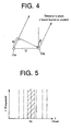
- Fig. 4 is an explanatory view illustrating a difference in distance between a sound source and two sound collecting microphones included in a sound collecting means in the sound source identifying apparatus of Fig. 1;
- Fig. 5 is a graph illustrating an operation of a directional filter included in the sound processing means in the sound source identifying apparatus of Fig. 1;
- Fig. 6 is a graph illustrating the extraction of two pieces of sound information for a sound from a single sound source performed in the sound processing means in the sound source identifying apparatus of Fig. 1;
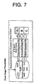
- Fig. 7 is an explanatory view illustrating the extraction of sound information from each sound source performed by the directional filter in the sound processing means in the sound source identifying apparatus of Fig. 1;
- Fig. 8 is a flow chart illustrating a method of operating the sound source identifying apparatus of Fig. 1;
- Fig. 9 is a pictorial diagram illustrating a portion of consecutive image pictures taken by the imaging means in the sound source identifying apparatus of Fig. 1; and
- Fig. 10 is a graph illustrating information as to positions determined by the image processing means on a variety of bases of an object that can be a sound source in the sound source identifying apparatus of Fig. 1.
-
- Hereinafter, the present invention for a sound source identifying apparatus and method will be described in detail with respect to presently best forms of embodiments thereof illustrated in the drawing figures.
- Fig. 1 shows a form of embodiment of the sound source identifying apparatus according to the present invention.
- Referring to Fig. 1, the sound
source identifying apparatus 10 includes a sound collecting means 11, an imaging means 12, an image processing means 13, a sound processing means 14 and a control means 15. - The sound collecting means 11 is designed to capture sounds from a plurality of sound sources, for example, three talkers, with a pair of sound collecting microphones 11a and 11b juxtaposed with each other across a preselected spacing D as indicated in Fig. 1 and opposed to the sound sources and to process the captured sounds. While the disposition of these sound collecting microphones may be set in any suitable manner, in the example shown they are provided at opposite sides of the imaging means 12, namely at its right hand and left hand sides.
- The imaging means 12 is constituted, for example, of a CCD (charge coupled device) camera and is designed as shown in Fig. 2 to make image pictures of a plurality of sound sources, e.g., three talkers A, B, and C, consecutively.
- The image processing means 13 is designed to derive information as to the locations of objects that can be sound sources, in images taken by the imaging means 12, and based on their color, shape or movement. It should be noted here that the term "movement" is intended to include vibrations.
- In this case, the image processing means 13 sets up in and for the image picture taken by the imaging means 12, frames A1, B1 and C1 for the three talkers A, B and C according to the color (i.e., the color of the skin of a human being) and height as shown in Fig. 3(B). Then, as shown in Fig. 3(C) the image processing means 13 selects center points A2, B2 and C2 of these frames A1, B1 and C1 (indicated in Fig. 3 by the + marks) as the respective locations of the objects to be possibly sound sources and takes their respective horizontal coordinates A3, B3 and C3 as information of these positions.
- At this point, it should be noted that the reason why the words "objects" "that can be", "possibly being" or "possibly as" "sound sources" are used here is that it has not necessarily be clear as yet from image recognition alone if they are indeed sound sources or not.
- Preferably, in order to simplify the above image processing, the image processing means 13 prior thereto should have rough directions A0, B0 and C0 of these sound sources (see Fig. 3(A)) entered therein that are determined by the sound processing means 14 to be described in detail below. Thus, having narrowed the respective regions of image processing of the sound sources into the rough directions A0, B0 and C0, the image processing means 13 derives information A3, B3 and C3 as to the respective locations as mentioned above of the objects that can be the sound sources by effecting the image processing within the narrowed regions of the rough directions A0, B0 and C0.
- The sound processing means 14 is designed to localize the locations of the sound sources based, for example, on the sound information derived from the microphones in the sound collecting means 11 and the position information A3, B3 and C3 derived by the image processing means 13.
- In the identification of the positions of the sound sources, the sound information may be based on a difference in phase and a difference in intensity between two pieces of sound information received by the right hand side and left hand side sound collecting microphones 11a and 11b, respectively.
- Thus in deriving sound information from a given sound source, as shown in Fig. 4 use may be made here of the fact that changing as a function of the direction in which a sound from the sound source propagates arriving at the two sound collecting microphones 11a and 11b ( = 0 when the sound source is in the front, a minus when it is in the left and a plus when it is in the right of them), a difference d between distances from the sound source to the two microphones 11a and 11b (expressed by equation: d = D sin ) causes the sound to vary in phase and also by damping to vary in intensity as it arrives them.
- Further, because the location of the sound source is not clear as yet, the sound processing means 14 here effects processing as mentioned above over the entire ranges of angles: -90 degrees ≦ ≦+90 degrees. In this case, the processing operation may be lightened by, for example, processing every angular interval, e.g., 5 degrees of .
- The sound processing means 15 first selects or determines rough directions A0, B0 and C0 of the sound sources based on sound information left and right from the sound collecting means 11. This follows the conventional sound source identifying technique yielding an accuracy of ± 10 degrees.
- And, the sound processing means 14 outputs these rough directions A0, B0 and C0 for entry into the image processing means 13.
- Further, the sound processing means 14 with reference to the position information A3, B3 and C3 entered therein from the image processing means 13 localizes the locations of the sound sources based again on the sound information narrowed into the ranges of the position information A3, B3 and C3, namely in the ranges of the position information A3, B3 and C3.
- In this case, the sound processing means 14 localizes the locations of the sound sources by making an appropriate choice of what are called directional filters for the sound sources A, B and C, respectively.
- Here, prepared so as to selectively extract sound information only at a particular time t0 such directional filters are stored as in a control table for the directions of the sound sources in an auxiliary storage means (not shown) in the control means 15, and are identified and selected as appropriate by the sound processing means 14 from the auxiliary storage means based on the position information A3, B3 and C3 from the image processing means 13.
- This permits pieces of sound information emitted concurrently from sound sources and collected by the sound collecting microphones 11a and 11b to be acquired when as shown in Fig. 6 a piece of sound information is given in the right hand side at time t1 and then another piece of information in the left hand side is taken out at time t2 that is after a delay time Δ t following it (t2 = t1 + Δt). Note, however, that Δ t can yet be negative.
- In this way, the selection of a particular directional filters by the sound processing means 14 with respect to each of the sound sources A, B and C possessing a directional information that is accurate to a certain extent enables their respective pieces of sound information to be obtained from the mixture of sounds as shown in Fig. 7.
- It should be noted at this point that narrowing the respective ranges of the directions of the sound sources by the pieces of position information A3, B3 and C3 makes it unnecessary for the sound processing means 14 to conduct processing over the entire range of angles for (- 90 degrees ≦ ≦ + 90 degrees) and makes it sufficient for the same to process a certain narrowed range of angles about the pieces of position information A3, B3 and C3.
- The control means 15 that may, for example, be comprised of a computer is designed to control the operations of the sound collecting means 11, the imaging means 12, the image processing means 13 and the sound processing means 14. The control means 15 as mentioned above has the directional filters stored as preset in the auxiliary storage means (not shown) therein.
- Constructed as mentioned above, the sound
source identifying apparatus 10 according to the present form of embodiment operates as described below, in accordance with the flow chart shown in Fig. 8. - Referring to Fig. 8, in step ST1 the control means 15 acts on the sound collecting means 11 to cause each of the sound collecting microphones 11a and 11b to collect sound from sound sources A, B and C, while in the mean time the control means 15 also acts on the imaging means 12 to cause it to image the sound sources consecutively in step ST2.
- Next, in step ST3 the control means 15 acts on the sound processing means 14 to cause it to select or determine rough directions A0, B0 and C0 in which the sound sources are located, respectively (see Fig. 3(A)), based on pieces of sound information for a difference between the phases and a difference between the intensities that the sound from each of the sound sources has as it is collected by the two microphones, respectively, in the sound collecting means 11. Then, all the harmonic structures in which any phase difference exists are examined to roughly separate the sound sources from the mixture sound. As a postscript, a harmonic structure is made a standard as an example of the signal for each of frequency bands arbitrarily divided into.
- Subsequently, in step ST4 the control means 15 acts on the image processing means 13 to cause it to select or determine position information A3, B3 and C3 (see Fig. 3(C)) as to objects as possible sound sources according to an color and/or shape thereof in image pictures received from the imaging means 12, and within the ranges of the rough directions received from the sound processing means 14.
- Thereafter, in step ST5 the control means 15 acts on the sound processing means 14 to cause it to localize the locations of the sound sources A, B and C according to the sound information received from the sound collecting means within a given range of angles for the position information A3, B3 and C3 received from the image processing means 14.
- Finally, in step ST6 the sound processing means 14 selects a particular directional filter to selectively extract sound information of a same sound from a same sound source and with a particular time delay. Without processing sound information of another, erroneous harmonic structure, this reduces the error and increases the sound source separation efficiency.
- In this manner, it will be seen that the sound
source identifying apparatus 10 according to the illustrated form of embodiment of the present invention in which in identifying a sound source, the sound processing means 14 is made to operate based not only on sound information received from the sound collecting means 11 but also on an image picture imaged by the imaging means 12, thus while referring to position information A3, B3, C3 of an object that can be the sound source, has the ability to identify a sound source with an accuracy increased from that of around ± 10 degrees attainable with the conventional system in which only sound information from the sound collecting means 11 is based on. - It is further seen that enhancing the accuracy of localizing the location of a sound source by refining sound information that beforehand roughly separates the sound source from another sound source with position information derived from image information makes its identification reliable even if they are close to each other.
- More specifically, if three talkers as sound sources are imaged by the imaging means 12 consecutively, for example image pictures are obtainable as shown in Fig. 9 in which they are of the 7th, 51st, 78th and 158th frames of all the pictures consecutively imaged.
- Here, these talkers' faces are actually lying as shown in Fig. 10(A) from which it is apparent that the talkers are positioned at around -30 degrees, 0 degree and +20 degrees of directional angle, respectively.
- Then, if determination is made to locate these objects possibly as the sound sources by the image processing means 13 processing the images only on the basis of the color, it is seen as shown in the graph of Fig. 10(B) that various other objects in the image pictures are recognized, too, as sound sources by mistake. If, however, both the color and height were based on in the image processing, the mistake is seen to decrease as shown in the graph of Fig. 10(C).
- Further, if the image processing means 13 is caused to process the images based on the color only while referring to the rough directions A0, B0 and C0 received from the sound processing means 14, the mistake is seen to decrease still more as shown in the graph of Fig. 10(D).
- Yet further, if the image processing means 13 is caused to process the images based on both the color and height while referring to the rough directions A0, B0 and C0 received from the sound processing means 14, it is apparent that the sound sources can be determined as their position information with an accuracy that compares favorably with the actual face position shown in Fig. 10(A), that is with considerable certainty.
- While in the example mentioned above the horizontal coordinates A3,B3 and C3 of the center positions A2, B2 and C2 of the frames A1, B1 and C1 in the pictures imaged consecutively of the objects that can be the sound sources are used to provide information as to locations thereof, use may be made of horizontal and vertical coordinates to provide information as to locations thereof.
- Further, in the example mentioned above the image processing means 13 is designed to select or determine information as to the locations of the objects that can be the sound sources on the basis of the color and shape (e.g., height) of the objects in the pictures imaged consecutively.
- Still further, while in the example mentioned above the image processing means 13 is designed to effect image processing with reference to the rough directions A0, B0 and C0 received from the sound processing means 14, the invention broadly is not limited thereto but may have information selected or determined as to the locations of the objects that can be the sound sources only on the basis of pictorial information received from the imaging means 12.
- In order to detect the direction in which a sound source is located, an active element such as in the form of a badge carrying magnetism may be attached to the sound source to determine the direction in which the magnetism is emitted by using a magnetic sensing device as its detecting means. The direction detected by the magnetic sensing means may be fed back to the sound processing means and used by the latter to prepare a directional filter, thereby separating the sound source.
- In case the sound source is a person, its emission of a heat ray renders an infrared detector usable to detect the direction in which the sound source is located.
- As described in the foregoing, it is seen that the present invention according to which in identifying a sound source based on sound information the direction in which the sound source is located is narrowed based on information as to its image and information as to its located direction detected while with reference to information as to the location of an object that can be the sound source, makes it unnecessary to process the sound information omnidirectionally or over all the directions in identifying the sound source, makes it possible to identify the sound source with greater certainty, makes a lesser amount of processable information sufficient and makes it possible to reduce the time for processing. Accordingly, a highly advantageous sound source identifying apparatus and method are provided in accordance with the present invention, which make it possible to identify a plurality of sound sources with due accuracy by means of a pair of microphones.
- Although the present invention has hereinbefore been set forth with respect to certain illustrative forms of embodiments thereof, it will readily be appreciated to be obvious to a person skilled in the art that many alternations thereof, omissions therefrom and additions thereto can be made without departing from the essences of scope of the present invention. Accordingly, it should be understood that the invention is not intended to be limited to the specific forms of embodiment thereof set forth below, but to include all possible forms of embodiment thereof that can be made within the scope with respect to the features specifically set forth in the appended claims and encompasses all the equivalents thereof.
- As will be appreciated from the foregoing description, a sound source identifying apparatus and method according to the present invention are highly useful as a sound source identifying apparatus and method whereby the location of an object as a sound source is identified with due certainty based on both sound and image information and the use of its position information permits each of such sound sources to be separated from mixed sounds with due accuracy. Claims:
Claims (15)
- A sound source identifying apparatus, comprising:a sound collecting means for capturing sounds from a plurality of sound sources with a pair of sound collecting microphones juxtaposed with each other across a preselected spacing and opposed to the sound sources and for processing the captured sounds;either or both of an imaging means and a sensing means, the imaging means being adapted to consecutively image objects that can be said sound sources, said sensing means being for sensing said objects possibly being said sound sources;an image processing means for deriving information as to locations of said objects possibly being said sound sources, from either or both of image pictures imaged by said imaging means and directional information of said objects sensed by said sensing means;a sound processing means for localizing the locations of said sound sources based on sound information of said sounds captured by said sound collecting means and position information derived by said image processing means; anda control means for controlling operations of said sound collecting means, said imaging means and/or said sensing means, said image processing means, and said sound processing means.
- A sound source identifying apparatus as set forth in claim 1, characterized in that said sound processing means includes directional filters, each of which is adapted to extract sound information at a particular time instant selectively.
- A sound source identifying apparatus as set forth in claim 1 or claim 2, characterized in that said sound processing means has a function to derive information as to rough directions in which said objects possibly being the sound sources are located.
- A sound source identifying apparatus as set froth in any one of claim 1 to claim 3, characterized in that said sensing means is adapted to sense said objects possibly being said sound sources in response to magnetism thereof.
- A sound source identifying apparatus as set forth in any one of claim 1 to claim 3, characterized in that said sensing means is adapted to sense said objects possibly being said sound sources in response to infrared rays that they emit.
- A sound source identifying apparatus as set forth in any one of claim 1 to claim 3, characterized in that said objects possibly being said sound sources have each a material carrying magnetism attached thereto.
- A sound source identifying method, characterized in that it comprises:a first step of capturing sounds from a plurality of sound sources with a pair of sound collecting microphones juxtaposed with each other across a preselected spacing and opposed to the sound sources and for processing the captured sounds, in a sound collecting means;a second step, conducted concurrently with the first step, of consecutively imaging objects that can be said sound sources and/or sensing directions in which said objects are located;a third step of deriving information as to locations of said objects possibly being said sound sources, from either or both of image pictures imaged, and the directions sensed, in the second step; anda fourth step of localizing locations of said sound sources based on sound information of the sounds collected in the first step and position information derived in the third step.
- A sound source identifying method as set forth in claim 7, characterized in that it further includes a fifth step of deriving information as to rough locations of said sound sources only from the sound information of said sounds collected in said first step; and that said third step includes narrowing in advance directions of said sound sources based on the rough position information derived in said fifth step, thereby deriving said position information of said objects possibly being said sound sources.
- A sound source identifying method as set forth in claim 8, characterized in that said fifth step roughly derives the directions of said sound sources from sound information for a difference between phases and a difference between intensities which each of said sounds has when acquired by said sound collecting microphones, respectively.
- A sound source identifying method as set forth in any one of claim 7 to claim 9, characterized in that said position information of said objects possibly being said sound sources is derived in said third step on the basis of either or both of a color and a shape of a said object.
- A sound source identifying method as set forth in claim 7, characterized in that said fourth step localizes the locations of said sound sources by selecting particular preset directional filters in response to the position information derived in said third step to extract sound information from each of said sound sources.
- A sound source identifying method as set forth in any one of claim 7 to claim 11, characterized in that the positions of said sound sources are determined in said fourth or fifth step on the basis of a signal in each of frequency bands arbitrarily divided into based on the sound information obtained in said first step.
- A sound source identifying method as set forth in any one of claim 7 to claim 9, claim 11 and claim 12, characterized in that said position information of a said object possibly being a said sound source is derived from a movement of said object.
- A sound source identifying method as set forth in any one of claim 7 to claim 13, characterized in that a said direction is sensed in response to magnetism.
- A sound source identifying method as set forth in any one of claim 7 to claim 13, characterized in that said direction is sensed in response to an infrared ray.
Applications Claiming Priority (3)
| Application Number | Priority Date | Filing Date | Title |
|---|---|---|---|
| JP16518299 | 1999-06-11 | ||
| JP16518299A JP3195920B2 (en) | 1999-06-11 | 1999-06-11 | Sound source identification / separation apparatus and method |
| PCT/JP2000/003695 WO2000077537A1 (en) | 1999-06-11 | 2000-06-07 | Method and apparatus for determining sound source |
Publications (3)
| Publication Number | Publication Date |
|---|---|
| EP1205762A1 true EP1205762A1 (en) | 2002-05-15 |
| EP1205762A4 EP1205762A4 (en) | 2005-07-06 |
| EP1205762B1 EP1205762B1 (en) | 2007-08-29 |
Family
ID=15807412
Family Applications (1)
| Application Number | Title | Priority Date | Filing Date |
|---|---|---|---|
| EP00935570A Expired - Lifetime EP1205762B1 (en) | 1999-06-11 | 2000-06-07 | Method and apparatus for determining sound source |
Country Status (6)
| Country | Link |
|---|---|
| US (1) | US7035418B1 (en) |
| EP (1) | EP1205762B1 (en) |
| JP (1) | JP3195920B2 (en) |
| DE (1) | DE60036216T2 (en) |
| ES (1) | ES2292441T3 (en) |
| WO (1) | WO2000077537A1 (en) |
Cited By (4)
| Publication number | Priority date | Publication date | Assignee | Title |
|---|---|---|---|---|
| US7403217B2 (en) | 2003-12-31 | 2008-07-22 | Mitel Networks Corporation | System and method of self-discovery and self-calibration in a video conferencing system |
| WO2010046736A1 (en) * | 2008-10-22 | 2010-04-29 | Sony Ericsson Mobile Communications Ab | System and method for generating multichannel audio with a portable electronic device eg using pseudo-stereo |
| WO2010149823A1 (en) * | 2009-06-23 | 2010-12-29 | Nokia Corporation | Method and apparatus for processing audio signals |
| CN104914409A (en) * | 2014-03-10 | 2015-09-16 | 李文嵩 | Intelligence residence positioning device |
Families Citing this family (29)
| Publication number | Priority date | Publication date | Assignee | Title |
|---|---|---|---|---|
| SE517765C2 (en) * | 2000-11-16 | 2002-07-16 | Ericsson Telefon Ab L M | Registration of moving images by means of a portable communication device and an accessory device co-located with the object |
| JP2004266343A (en) * | 2003-02-05 | 2004-09-24 | Matsushita Electric Ind Co Ltd | Image server and image server system, program for the same, and recording medium |
| WO2004084187A1 (en) * | 2003-03-17 | 2004-09-30 | Nagoya Industrial Science Research Institute | Object sound detection method, signal input delay time detection method, and sound signal processing device |
| JP4269883B2 (en) * | 2003-10-20 | 2009-05-27 | ソニー株式会社 | Microphone device, playback device, and imaging device |
| US20090018828A1 (en) * | 2003-11-12 | 2009-01-15 | Honda Motor Co., Ltd. | Automatic Speech Recognition System |
| JP2006245725A (en) * | 2005-03-01 | 2006-09-14 | Yamaha Corp | Microphone system |
| JP4441879B2 (en) * | 2005-06-28 | 2010-03-31 | ソニー株式会社 | Signal processing apparatus and method, program, and recording medium |
| JP4757786B2 (en) * | 2006-12-07 | 2011-08-24 | Necアクセステクニカ株式会社 | Sound source direction estimating apparatus, sound source direction estimating method, and robot apparatus |
| IL188156A0 (en) * | 2007-12-16 | 2008-11-03 | Maly Edelman | A method and system for protecting an area |
| US20100123785A1 (en) * | 2008-11-17 | 2010-05-20 | Apple Inc. | Graphic Control for Directional Audio Input |
| TWI402531B (en) * | 2009-06-29 | 2013-07-21 | Univ Nat Cheng Kung | Method for locating sound sorce and sound source locating system and computer program product using the same |
| US9094645B2 (en) * | 2009-07-17 | 2015-07-28 | Lg Electronics Inc. | Method for processing sound source in terminal and terminal using the same |
| TWI417563B (en) * | 2009-11-20 | 2013-12-01 | Univ Nat Cheng Kung | An soc design for far-field sound localization |
| US9955209B2 (en) | 2010-04-14 | 2018-04-24 | Alcatel-Lucent Usa Inc. | Immersive viewer, a method of providing scenes on a display and an immersive viewing system |
| US9294716B2 (en) | 2010-04-30 | 2016-03-22 | Alcatel Lucent | Method and system for controlling an imaging system |
| US8754925B2 (en) * | 2010-09-30 | 2014-06-17 | Alcatel Lucent | Audio source locator and tracker, a method of directing a camera to view an audio source and a video conferencing terminal |
| US8185387B1 (en) | 2011-11-14 | 2012-05-22 | Google Inc. | Automatic gain control |
| US9008487B2 (en) | 2011-12-06 | 2015-04-14 | Alcatel Lucent | Spatial bookmarking |
| JP6216169B2 (en) * | 2012-09-26 | 2017-10-18 | キヤノン株式会社 | Information processing apparatus and information processing method |
| JP2014143678A (en) * | 2012-12-27 | 2014-08-07 | Panasonic Corp | Voice processing system and voice processing method |
| CN103902963B (en) * | 2012-12-28 | 2017-06-20 | 联想(北京)有限公司 | The method and electronic equipment in a kind of identification orientation and identity |
| KR101997449B1 (en) * | 2013-01-29 | 2019-07-09 | 엘지전자 주식회사 | Mobile terminal and controlling method thereof |
| EP2879047A3 (en) * | 2013-11-28 | 2015-12-16 | LG Electronics Inc. | Mobile terminal and controlling method thereof |
| CN104683933A (en) | 2013-11-29 | 2015-06-03 | 杜比实验室特许公司 | Audio object extraction method |
| JP6297858B2 (en) * | 2014-02-25 | 2018-03-20 | 株式会社熊谷組 | Sound source estimation image creation device |
| DE102014217598A1 (en) * | 2014-09-03 | 2016-03-03 | Gesellschaft zur Förderung angewandter Informatik e.V. | Method and arrangement for acquiring acoustic and optical information and a corresponding computer program and a corresponding computer-readable storage medium |
| CN105070304B (en) * | 2015-08-11 | 2018-09-04 | 小米科技有限责任公司 | Realize method and device, the electronic equipment of multi-object audio recording |
| CN109696658B (en) | 2017-10-23 | 2021-08-24 | 京东方科技集团股份有限公司 | Acquisition device, sound acquisition method, sound source tracking system and sound source tracking method |
| JP6589041B1 (en) * | 2018-01-16 | 2019-10-09 | ハイラブル株式会社 | Speech analysis apparatus, speech analysis method, speech analysis program, and speech analysis system |
Citations (4)
| Publication number | Priority date | Publication date | Assignee | Title |
|---|---|---|---|---|
| EP0689356A2 (en) * | 1994-06-20 | 1995-12-27 | AT&T Corp. | Voice-following video system |
| WO1997043856A1 (en) * | 1996-05-16 | 1997-11-20 | Unisearch Limited | Compression and coding of audio-visual services |
| US5786846A (en) * | 1995-03-09 | 1998-07-28 | Nec Corporation | User interface of a video communication terminal unit and a method for notifying a terminal user's deviation from an appropriate shoot range |
| JPH1118194A (en) * | 1997-06-26 | 1999-01-22 | Fujitsu Ltd | Microphone array unit |
Family Cites Families (20)
| Publication number | Priority date | Publication date | Assignee | Title |
|---|---|---|---|---|
| JP3232608B2 (en) * | 1991-11-25 | 2001-11-26 | ソニー株式会社 | Sound collecting device, reproducing device, sound collecting method and reproducing method, and sound signal processing device |
| JPH05244587A (en) * | 1992-02-26 | 1993-09-21 | Mitsubishi Electric Corp | Camera controller for television conference |
| US5402499A (en) * | 1992-08-07 | 1995-03-28 | Lsi Logic Corporation | Multimedia controller |
| JPH06105306A (en) * | 1992-09-16 | 1994-04-15 | Funai Denki Kenkyusho:Kk | Video conference system |
| JPH0739000A (en) | 1992-12-05 | 1995-02-07 | Kazumoto Suzuki | Selective extract method for sound wave in optional direction |
| JP2937009B2 (en) * | 1994-03-30 | 1999-08-23 | ヤマハ株式会社 | Sound image localization control device |
| JP3714706B2 (en) * | 1995-02-17 | 2005-11-09 | 株式会社竹中工務店 | Sound extraction device |
| JPH0933330A (en) * | 1995-07-17 | 1997-02-07 | Nippon Telegr & Teleph Corp <Ntt> | Acoustic signal separation method and device for executing the method |
| GB2309105A (en) * | 1996-01-12 | 1997-07-16 | Ibm | Intuitive GUI in the form of a representation of a physical environment |
| JP3537962B2 (en) | 1996-08-05 | 2004-06-14 | 株式会社東芝 | Voice collecting device and voice collecting method |
| EP1016002A4 (en) * | 1996-09-04 | 2000-11-15 | David A Goldberg | Method and system for obtaining person-specific images in a public venue |
| JP3355598B2 (en) | 1996-09-18 | 2002-12-09 | 日本電信電話株式会社 | Sound source separation method, apparatus and recording medium |
| US6021206A (en) * | 1996-10-02 | 2000-02-01 | Lake Dsp Pty Ltd | Methods and apparatus for processing spatialised audio |
| TW379309B (en) * | 1997-05-16 | 2000-01-11 | Samsung Electronics Co Ltd | Signal management apparatus and method using on screen display |
| US6072522A (en) * | 1997-06-04 | 2000-06-06 | Cgc Designs | Video conferencing apparatus for group video conferencing |
| JPH1141577A (en) | 1997-07-18 | 1999-02-12 | Fujitsu Ltd | Speaker position detector |
| US6192134B1 (en) * | 1997-11-20 | 2001-02-20 | Conexant Systems, Inc. | System and method for a monolithic directional microphone array |
| US5940118A (en) * | 1997-12-22 | 1999-08-17 | Nortel Networks Corporation | System and method for steering directional microphones |
| US6005610A (en) * | 1998-01-23 | 1999-12-21 | Lucent Technologies Inc. | Audio-visual object localization and tracking system and method therefor |
| US6311155B1 (en) * | 2000-02-04 | 2001-10-30 | Hearing Enhancement Company Llc | Use of voice-to-remaining audio (VRA) in consumer applications |
-
1999
- 1999-06-11 JP JP16518299A patent/JP3195920B2/en not_active Expired - Fee Related
-
2000
- 2000-06-07 US US09/926,673 patent/US7035418B1/en not_active Expired - Lifetime
- 2000-06-07 WO PCT/JP2000/003695 patent/WO2000077537A1/en active IP Right Grant
- 2000-06-07 ES ES00935570T patent/ES2292441T3/en not_active Expired - Lifetime
- 2000-06-07 EP EP00935570A patent/EP1205762B1/en not_active Expired - Lifetime
- 2000-06-07 DE DE60036216T patent/DE60036216T2/en not_active Expired - Lifetime
Patent Citations (4)
| Publication number | Priority date | Publication date | Assignee | Title |
|---|---|---|---|---|
| EP0689356A2 (en) * | 1994-06-20 | 1995-12-27 | AT&T Corp. | Voice-following video system |
| US5786846A (en) * | 1995-03-09 | 1998-07-28 | Nec Corporation | User interface of a video communication terminal unit and a method for notifying a terminal user's deviation from an appropriate shoot range |
| WO1997043856A1 (en) * | 1996-05-16 | 1997-11-20 | Unisearch Limited | Compression and coding of audio-visual services |
| JPH1118194A (en) * | 1997-06-26 | 1999-01-22 | Fujitsu Ltd | Microphone array unit |
Non-Patent Citations (3)
| Title |
|---|
| NAKATANI T ET AL: "Harmonic sound stream segregation using localization and its application to speech stream segregation" SPEECH COMMUNICATION, ELSEVIER SCIENCE PUBLISHERS, AMSTERDAM, NL, vol. 27, no. 3-4, April 1999 (1999-04), pages 209-222, XP004163251 ISSN: 0167-6393 * |
| PATENT ABSTRACTS OF JAPAN vol. 1999, no. 04, 30 April 1999 (1999-04-30) -& JP 11 018194 A (FUJITSU LTD), 22 January 1999 (1999-01-22) -& US 6 317 501 B1 (MATSUO NAOSHI) 13 November 2001 (2001-11-13) * |
| See also references of WO0077537A1 * |
Cited By (6)
| Publication number | Priority date | Publication date | Assignee | Title |
|---|---|---|---|---|
| US7403217B2 (en) | 2003-12-31 | 2008-07-22 | Mitel Networks Corporation | System and method of self-discovery and self-calibration in a video conferencing system |
| WO2010046736A1 (en) * | 2008-10-22 | 2010-04-29 | Sony Ericsson Mobile Communications Ab | System and method for generating multichannel audio with a portable electronic device eg using pseudo-stereo |
| WO2010149823A1 (en) * | 2009-06-23 | 2010-12-29 | Nokia Corporation | Method and apparatus for processing audio signals |
| US9888335B2 (en) | 2009-06-23 | 2018-02-06 | Nokia Technologies Oy | Method and apparatus for processing audio signals |
| CN104914409A (en) * | 2014-03-10 | 2015-09-16 | 李文嵩 | Intelligence residence positioning device |
| CN104914409B (en) * | 2014-03-10 | 2017-11-07 | 李文嵩 | Intelligent dwelling positioner |
Also Published As
| Publication number | Publication date |
|---|---|
| EP1205762B1 (en) | 2007-08-29 |
| DE60036216D1 (en) | 2007-10-11 |
| JP2000356674A (en) | 2000-12-26 |
| ES2292441T3 (en) | 2008-03-16 |
| DE60036216T2 (en) | 2008-05-15 |
| WO2000077537A1 (en) | 2000-12-21 |
| US7035418B1 (en) | 2006-04-25 |
| EP1205762A4 (en) | 2005-07-06 |
| JP3195920B2 (en) | 2001-08-06 |
Similar Documents
| Publication | Publication Date | Title |
|---|---|---|
| EP1205762A1 (en) | Method and apparatus for determining sound source | |
| US8396282B1 (en) | Method and system for computing fused saliency maps from multi-modal sensory inputs | |
| CN103688292B (en) | Image display device and method for displaying image | |
| US20060097172A1 (en) | Imaging apparatus, medium, and method using infrared rays with image discrimination | |
| JP3727798B2 (en) | Image surveillance system | |
| US11468789B2 (en) | Electroencephalogram—controlled video input and auditory display blind guiding apparatus and method | |
| US10964326B2 (en) | System and method for audio-visual speech recognition | |
| US10992870B1 (en) | Intelligent zoom method and video system implementing same | |
| US20140086551A1 (en) | Information processing apparatus and information processing method | |
| US9355641B2 (en) | Monitoring device using selective attention model and method for monitoring same | |
| JP7194897B2 (en) | Signal processing device and signal processing method | |
| JP4403477B2 (en) | Image processing apparatus and image processing method | |
| JP4208450B2 (en) | Face image monitoring system | |
| JPH0723012A (en) | Audience rating survey system | |
| JP2004062393A (en) | Method and device for determining attention | |
| JP2004272933A (en) | Face image monitoring system | |
| KR101542647B1 (en) | A Method for Processing Audio Signal Using Speacker Detection and A Device thereof | |
| JPH08210847A (en) | Image processing method | |
| CN107548483A (en) | Control method, control device, system and the motor vehicles for including such control device | |
| JPH0624035B2 (en) | Driving path identification device | |
| JPH0325390A (en) | Body identification device | |
| CN112364832B (en) | Face recognition method and system based on Euler image amplification | |
| JP2003179930A (en) | Method and apparatus for extracting dynamic object | |
| JP4259786B2 (en) | Information acquisition system | |
| US11055876B2 (en) | Method of determining information about imaging position and apparatus for performing the same |
Legal Events
| Date | Code | Title | Description |
|---|---|---|---|
| PUAI | Public reference made under article 153(3) epc to a published international application that has entered the european phase |
Free format text: ORIGINAL CODE: 0009012 |
|
| 17P | Request for examination filed |
Effective date: 20011227 |
|
| AK | Designated contracting states |
Kind code of ref document: A1 Designated state(s): AT BE CH CY DE DK ES FI FR GB GR IE IT LI LU MC NL PT SE |
|
| AX | Request for extension of the european patent |
Free format text: AL;LT;LV;MK;RO;SI |
|
| RBV | Designated contracting states (corrected) |
Designated state(s): DE ES FR GB IT NL |
|
| RAP1 | Party data changed (applicant data changed or rights of an application transferred) |
Owner name: JAPAN SCIENCE AND TECHNOLOGY AGENCY |
|
| A4 | Supplementary search report drawn up and despatched |
Effective date: 20050520 |
|
| RIC1 | Information provided on ipc code assigned before grant |
Ipc: 7H 04N 7/18 B Ipc: 7H 04N 7/15 B Ipc: 7G 01S 5/18 B Ipc: 7H 04R 1/40 B Ipc: 7G 01S 3/808 A Ipc: 7H 04R 5/027 B |
|
| GRAP | Despatch of communication of intention to grant a patent |
Free format text: ORIGINAL CODE: EPIDOSNIGR1 |
|
| GRAS | Grant fee paid |
Free format text: ORIGINAL CODE: EPIDOSNIGR3 |
|
| GRAA | (expected) grant |
Free format text: ORIGINAL CODE: 0009210 |
|
| AK | Designated contracting states |
Kind code of ref document: B1 Designated state(s): DE ES FR GB IT NL |
|
| REG | Reference to a national code |
Ref country code: GB Ref legal event code: FG4D |
|
| REF | Corresponds to: |
Ref document number: 60036216 Country of ref document: DE Date of ref document: 20071011 Kind code of ref document: P |
|
| REG | Reference to a national code |
Ref country code: ES Ref legal event code: FG2A Ref document number: 2292441 Country of ref document: ES Kind code of ref document: T3 |
|
| ET | Fr: translation filed | ||
| PLBE | No opposition filed within time limit |
Free format text: ORIGINAL CODE: 0009261 |
|
| STAA | Information on the status of an ep patent application or granted ep patent |
Free format text: STATUS: NO OPPOSITION FILED WITHIN TIME LIMIT |
|
| 26N | No opposition filed |
Effective date: 20080530 |
|
| REG | Reference to a national code |
Ref country code: DE Ref legal event code: R082 Ref document number: 60036216 Country of ref document: DE Representative=s name: SPARING - ROEHL - HENSELER, DE |
|
| REG | Reference to a national code |
Ref country code: NL Ref legal event code: SD Effective date: 20130529 |
|
| REG | Reference to a national code |
Ref country code: DE Ref legal event code: R082 Ref document number: 60036216 Country of ref document: DE Representative=s name: SPARING - ROEHL - HENSELER, DE Effective date: 20130419 Ref country code: DE Ref legal event code: R081 Ref document number: 60036216 Country of ref document: DE Owner name: NAKAGAWA, YUKIKO, JP Free format text: FORMER OWNER: JAPAN SCIENCE AND TECHNOLOGY AGENCY, KAWAGUCHI-SHI, JP Effective date: 20130419 Ref country code: DE Ref legal event code: R081 Ref document number: 60036216 Country of ref document: DE Owner name: NAKAGAWA, YUKIKO, KAWASAKI-SHI, JP Free format text: FORMER OWNER: JAPAN SCIENCE AND TECHNOLOGY AGENCY, KAWAGUCHI-SHI, SAITAMA, JP Effective date: 20130419 Ref country code: DE Ref legal event code: R081 Ref document number: 60036216 Country of ref document: DE Owner name: NAKAGAWA, YUKIKO, JP Free format text: FORMER OWNER: JAPAN SCIENCE AND TECHNOLOGY AGENCY, KAWAGUCHI-SHI, SAITAMA, JP Effective date: 20130419 Ref country code: DE Ref legal event code: R082 Ref document number: 60036216 Country of ref document: DE Representative=s name: BARDEHLE PAGENBERG PARTNERSCHAFT MBB PATENTANW, DE Effective date: 20130419 |
|
| REG | Reference to a national code |
Ref country code: GB Ref legal event code: 732E Free format text: REGISTERED BETWEEN 20130606 AND 20130612 |
|
| REG | Reference to a national code |
Ref country code: FR Ref legal event code: TP Owner name: YUKIKO NAKAGAWA, JP Effective date: 20130702 |
|
| REG | Reference to a national code |
Ref country code: FR Ref legal event code: PLFP Year of fee payment: 16 |
|
| REG | Reference to a national code |
Ref country code: DE Ref legal event code: R082 Ref document number: 60036216 Country of ref document: DE Representative=s name: BARDEHLE PAGENBERG PARTNERSCHAFT MBB PATENTANW, DE Ref country code: DE Ref legal event code: R081 Ref document number: 60036216 Country of ref document: DE Owner name: NAKAGAWA, YUKIKO, JP Free format text: FORMER OWNER: NAKAGAWA, YUKIKO, KAWASAKI-SHI, KANAGAWA, JP |
|
| REG | Reference to a national code |
Ref country code: FR Ref legal event code: CA Effective date: 20160418 |
|
| REG | Reference to a national code |
Ref country code: FR Ref legal event code: PLFP Year of fee payment: 17 |
|
| REG | Reference to a national code |
Ref country code: FR Ref legal event code: CA Effective date: 20160509 |
|
| REG | Reference to a national code |
Ref country code: FR Ref legal event code: PLFP Year of fee payment: 18 |
|
| REG | Reference to a national code |
Ref country code: FR Ref legal event code: PLFP Year of fee payment: 19 |
|
| PGFP | Annual fee paid to national office [announced via postgrant information from national office to epo] |
Ref country code: NL Payment date: 20180613 Year of fee payment: 19 Ref country code: DE Payment date: 20180522 Year of fee payment: 19 |
|
| PGFP | Annual fee paid to national office [announced via postgrant information from national office to epo] |
Ref country code: FR Payment date: 20180511 Year of fee payment: 19 |
|
| PGFP | Annual fee paid to national office [announced via postgrant information from national office to epo] |
Ref country code: GB Payment date: 20180606 Year of fee payment: 19 Ref country code: ES Payment date: 20180702 Year of fee payment: 19 Ref country code: IT Payment date: 20180625 Year of fee payment: 19 |
|
| REG | Reference to a national code |
Ref country code: DE Ref legal event code: R119 Ref document number: 60036216 Country of ref document: DE |
|
| REG | Reference to a national code |
Ref country code: NL Ref legal event code: MM Effective date: 20190701 |
|
| GBPC | Gb: european patent ceased through non-payment of renewal fee |
Effective date: 20190607 |
|
| PG25 | Lapsed in a contracting state [announced via postgrant information from national office to epo] |
Ref country code: GB Free format text: LAPSE BECAUSE OF NON-PAYMENT OF DUE FEES Effective date: 20190607 Ref country code: IT Free format text: LAPSE BECAUSE OF NON-PAYMENT OF DUE FEES Effective date: 20190607 Ref country code: DE Free format text: LAPSE BECAUSE OF NON-PAYMENT OF DUE FEES Effective date: 20200101 Ref country code: NL Free format text: LAPSE BECAUSE OF NON-PAYMENT OF DUE FEES Effective date: 20190701 |
|
| PG25 | Lapsed in a contracting state [announced via postgrant information from national office to epo] |
Ref country code: FR Free format text: LAPSE BECAUSE OF NON-PAYMENT OF DUE FEES Effective date: 20190630 |
|
| REG | Reference to a national code |
Ref country code: ES Ref legal event code: FD2A Effective date: 20201027 |
|
| PG25 | Lapsed in a contracting state [announced via postgrant information from national office to epo] |
Ref country code: ES Free format text: LAPSE BECAUSE OF NON-PAYMENT OF DUE FEES Effective date: 20190608 |